WO2021206172A1 - 加工方法 - Google Patents
加工方法 Download PDFInfo
- Publication number
- WO2021206172A1 WO2021206172A1 PCT/JP2021/015080 JP2021015080W WO2021206172A1 WO 2021206172 A1 WO2021206172 A1 WO 2021206172A1 JP 2021015080 W JP2021015080 W JP 2021015080W WO 2021206172 A1 WO2021206172 A1 WO 2021206172A1
- Authority
- WO
- WIPO (PCT)
- Prior art keywords
- axis
- rotary
- tool
- machining
- work
- Prior art date
Links
- 238000003754 machining Methods 0.000 title claims abstract description 50
- 238000000034 method Methods 0.000 title claims abstract description 16
- 238000012360 testing method Methods 0.000 claims abstract description 56
- 238000012937 correction Methods 0.000 claims abstract description 19
- 238000005259 measurement Methods 0.000 claims abstract description 13
- 238000012545 processing Methods 0.000 claims description 21
- 230000036544 posture Effects 0.000 claims description 19
- 238000003672 processing method Methods 0.000 claims 3
- 238000003860 storage Methods 0.000 description 12
- 239000000523 sample Substances 0.000 description 6
- 238000004519 manufacturing process Methods 0.000 description 2
- 238000010079 rubber tapping Methods 0.000 description 2
- 230000032683 aging Effects 0.000 description 1
- 239000002826 coolant Substances 0.000 description 1
- 238000010586 diagram Methods 0.000 description 1
Images


Classifications
-
- G—PHYSICS
- G05—CONTROLLING; REGULATING
- G05B—CONTROL OR REGULATING SYSTEMS IN GENERAL; FUNCTIONAL ELEMENTS OF SUCH SYSTEMS; MONITORING OR TESTING ARRANGEMENTS FOR SUCH SYSTEMS OR ELEMENTS
- G05B19/00—Programme-control systems
- G05B19/02—Programme-control systems electric
- G05B19/18—Numerical control [NC], i.e. automatically operating machines, in particular machine tools, e.g. in a manufacturing environment, so as to execute positioning, movement or co-ordinated operations by means of programme data in numerical form
- G05B19/401—Numerical control [NC], i.e. automatically operating machines, in particular machine tools, e.g. in a manufacturing environment, so as to execute positioning, movement or co-ordinated operations by means of programme data in numerical form characterised by control arrangements for measuring, e.g. calibration and initialisation, measuring workpiece for machining purposes
-
- B—PERFORMING OPERATIONS; TRANSPORTING
- B23—MACHINE TOOLS; METAL-WORKING NOT OTHERWISE PROVIDED FOR
- B23Q—DETAILS, COMPONENTS, OR ACCESSORIES FOR MACHINE TOOLS, e.g. ARRANGEMENTS FOR COPYING OR CONTROLLING; MACHINE TOOLS IN GENERAL CHARACTERISED BY THE CONSTRUCTION OF PARTICULAR DETAILS OR COMPONENTS; COMBINATIONS OR ASSOCIATIONS OF METAL-WORKING MACHINES, NOT DIRECTED TO A PARTICULAR RESULT
- B23Q1/00—Members which are comprised in the general build-up of a form of machine, particularly relatively large fixed members
- B23Q1/25—Movable or adjustable work or tool supports
- B23Q1/44—Movable or adjustable work or tool supports using particular mechanisms
- B23Q1/50—Movable or adjustable work or tool supports using particular mechanisms with rotating pairs only, the rotating pairs being the first two elements of the mechanism
- B23Q1/52—Movable or adjustable work or tool supports using particular mechanisms with rotating pairs only, the rotating pairs being the first two elements of the mechanism a single rotating pair
- B23Q1/522—Movable or adjustable work or tool supports using particular mechanisms with rotating pairs only, the rotating pairs being the first two elements of the mechanism a single rotating pair which is perpendicular to the working surface
-
- B—PERFORMING OPERATIONS; TRANSPORTING
- B23—MACHINE TOOLS; METAL-WORKING NOT OTHERWISE PROVIDED FOR
- B23Q—DETAILS, COMPONENTS, OR ACCESSORIES FOR MACHINE TOOLS, e.g. ARRANGEMENTS FOR COPYING OR CONTROLLING; MACHINE TOOLS IN GENERAL CHARACTERISED BY THE CONSTRUCTION OF PARTICULAR DETAILS OR COMPONENTS; COMBINATIONS OR ASSOCIATIONS OF METAL-WORKING MACHINES, NOT DIRECTED TO A PARTICULAR RESULT
- B23Q1/00—Members which are comprised in the general build-up of a form of machine, particularly relatively large fixed members
- B23Q1/25—Movable or adjustable work or tool supports
- B23Q1/44—Movable or adjustable work or tool supports using particular mechanisms
- B23Q1/50—Movable or adjustable work or tool supports using particular mechanisms with rotating pairs only, the rotating pairs being the first two elements of the mechanism
- B23Q1/54—Movable or adjustable work or tool supports using particular mechanisms with rotating pairs only, the rotating pairs being the first two elements of the mechanism two rotating pairs only
-
- B—PERFORMING OPERATIONS; TRANSPORTING
- B23—MACHINE TOOLS; METAL-WORKING NOT OTHERWISE PROVIDED FOR
- B23Q—DETAILS, COMPONENTS, OR ACCESSORIES FOR MACHINE TOOLS, e.g. ARRANGEMENTS FOR COPYING OR CONTROLLING; MACHINE TOOLS IN GENERAL CHARACTERISED BY THE CONSTRUCTION OF PARTICULAR DETAILS OR COMPONENTS; COMBINATIONS OR ASSOCIATIONS OF METAL-WORKING MACHINES, NOT DIRECTED TO A PARTICULAR RESULT
- B23Q17/00—Arrangements for observing, indicating or measuring on machine tools
- B23Q17/22—Arrangements for observing, indicating or measuring on machine tools for indicating or measuring existing or desired position of tool or work
-
- G—PHYSICS
- G05—CONTROLLING; REGULATING
- G05B—CONTROL OR REGULATING SYSTEMS IN GENERAL; FUNCTIONAL ELEMENTS OF SUCH SYSTEMS; MONITORING OR TESTING ARRANGEMENTS FOR SUCH SYSTEMS OR ELEMENTS
- G05B19/00—Programme-control systems
- G05B19/02—Programme-control systems electric
- G05B19/18—Numerical control [NC], i.e. automatically operating machines, in particular machine tools, e.g. in a manufacturing environment, so as to execute positioning, movement or co-ordinated operations by means of programme data in numerical form
- G05B19/404—Numerical control [NC], i.e. automatically operating machines, in particular machine tools, e.g. in a manufacturing environment, so as to execute positioning, movement or co-ordinated operations by means of programme data in numerical form characterised by control arrangements for compensation, e.g. for backlash, overshoot, tool offset, tool wear, temperature, machine construction errors, load, inertia
-
- G—PHYSICS
- G05—CONTROLLING; REGULATING
- G05B—CONTROL OR REGULATING SYSTEMS IN GENERAL; FUNCTIONAL ELEMENTS OF SUCH SYSTEMS; MONITORING OR TESTING ARRANGEMENTS FOR SUCH SYSTEMS OR ELEMENTS
- G05B2219/00—Program-control systems
- G05B2219/30—Nc systems
- G05B2219/37—Measurements
- G05B2219/37129—Mark, engrave workpiece at specific surface point for measurement, calibration
Definitions
- the present invention relates to a machining method using a machine tool having a rotary feed axis in addition to a linear feed axis having three orthogonal axes.
- Patent Document 1 describes a method of calculating a position error and an inclination error of the rotation axis of the rotation feed shaft of such a machine tool.
- the work table is rotated relative to the main axis to be positioned at at least three measurement positions having different rotation angles, and the center position of the reference sphere arranged on the work table is used as the main axis.
- Measured by the attached touch sensor calculate the direction vector of the rotation axis based on the center position of the reference sphere measured at each measurement position, and calculate the inclination error of the actual direction vector with respect to the reference direction vector of the rotation axis. It is designed to do.
- the present invention has a technical problem of solving such problems of the prior art, and even if the rotation axis of the rotation feed shaft has a position error, an inclination error, and a runout error, the work can be machined with high accuracy. It is intended to provide a method.
- a rotary tool attached to the spindle and a workpiece fixed to a rotary table are relatively placed.
- the test work is fixed on the rotary table, the test work is positioned in a plurality of postures, and the surface of the test work is surfaced with a rotary tool used during the main machining of the work.
- the predetermined portion of the Provided is a machining method in which the work is machined by correcting with a correction amount of the tool length of the rotary tool.
- a predetermined surface portion of the test work is machined before the main machining under the same conditions and environment as the actual machining (main machining), the surface portion is measured, and the center of the rotation axis is measured.
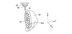
- the machine tool 11 includes a bed 13 as a base and a column 15 erected on the upper surface of the bed 13.
- a moving body 27 is arranged on the upper surface of the bed 13.
- the moving body 27 supports a rotary table 35 that rotates the work W via the tilt swivel table 28.
- the rotary table 35 has a work mounting surface 35a for fixing the work W.
- a saddle 17 is placed on the front of the column 15. Further, a spindle head 21 is arranged on the front surface of the saddle 17. A spindle 25 is attached to the spindle head 21. A rotary tool T for machining the work W is attached to the spindle 25. The rotary tool T processes the work W while rotating together with the spindle 25.
- the machine tool 11 in the present embodiment includes a moving device that changes the relative positions of the rotary tool T and the work W.
- a machine coordinate system with a predetermined position on the machine tool as the origin is set.
- the X-axis, Y-axis, and Z-axis that are orthogonal to each other in the machine coordinate system are predetermined.
- the direction in which the axis of the spindle 25 extends (vertical direction in FIG. 1) is referred to as the Z axis.
- the axis extending in the horizontal direction in which the moving body 27 moves is referred to as a Y axis.
- the axis extending in the horizontal direction in which the saddle 17 moves, that is, in the direction perpendicular to the Z axis and the Y axis is referred to as an X axis.
- the moving device can relatively move the rotary tool T and the work W in the X-axis direction, the Y-axis direction, and the Z-axis direction. Further, the moving device rotates the work W relative to the rotary tool T in the B-axis direction around the axis 52 of the inclined swivel table 28 and in the C-axis direction around the axis 53 of the rotary table 35. Can be done.
- the moving device includes an X-axis moving device that moves the rotary tool T relative to the work W in the X-axis direction.
- the X-axis moving device includes a pair of X-axis rails 19a, 19b formed on the front surface of the column 15.
- the saddle 17 is formed so as to be able to reciprocate along the X-axis rails 19a and 19b.
- the X-axis moving device moves the saddle 17 by a ball screw mechanism.
- the X-axis moving device includes an X-axis servomotor 20 that rotates the screw shaft of the ball screw mechanism.
- the X-axis moving device moves the saddle 17 by driving the X-axis servomotor 20.
- the spindle head 21 and the rotary tool T move in the X-axis direction together with the saddle 17.
- the moving device includes a Z-axis moving device that moves the rotary tool T relative to the work W in the Z-axis direction.
- the Z-axis moving device includes a pair of Z-axis rails 23a, 23b formed on the front surface of the saddle 17.
- the spindle head 21 is formed so as to be able to reciprocate along the Z-axis rails 23a and 23b.
- the Z-axis moving device moves the spindle head 21 by a ball screw mechanism.
- the Z-axis moving device includes a Z-axis servomotor 24 that rotates the screw shaft of the ball screw mechanism.
- the Z-axis moving device moves the spindle head 21 by driving the Z-axis servomotor 24.
- the rotary tool T moves in the Z-axis direction together with the spindle head 21. Further, inside the spindle head 21, a drive motor that rotates the spindle 25 around the axis is arranged.
- FIG. 3 shows a schematic perspective view of the Y-axis moving device according to the embodiment of the present embodiment.
- the moving device includes a Y-axis moving device that moves the rotary tool T relative to the work W in the Y-axis direction.
- the Y-axis moving device includes a pair of Y-axis rails 29a, 29b arranged on the upper surface of the bed 13.
- the moving body 27 is formed so as to be able to reciprocate along the Y-axis rails 29a and 29b.
- a cavity 15a is formed in the column 15 so that the moving body 27 can move in the Y-axis direction.
- the Y-axis moving device moves the moving body 27 by the ball screw mechanism 30.
- the Y-axis moving device includes a Y-axis servomotor 32 that rotates the screw shaft of the ball screw mechanism.
- the Y-axis moving device moves the moving body 27 by driving the Y-axis servomotor 32.
- the tilt swivel table 28 and the rotary table 35 move in the Y-axis direction together with the moving body 27.
- the moving device includes a B-axis rotating moving device that rotates the rotary tool T relative to the work W in the B-axis direction.
- the axis 52 of the B axis in this embodiment is not parallel to any of the X axis, the Y axis, and the Z axis. That is, the axis 52 of the B axis is inclined with respect to each of the three linear motion axes.
- the B-axis rotary moving device includes an inclined swivel table 28. Inside the moving body 27, a servomotor for rotating the inclined swivel table 28 is arranged. By driving the servomotor of the tilt swivel table 28, the tilt swivel table 28 rotates around the axis 52 of the B axis.
- the work W rotates in the B-axis direction together with the inclined swivel table 28 and the rotary table 35.
- the moving device in the present embodiment includes a C-axis rotating moving device that rotates the rotary tool T relative to the work W in the C-axis direction.
- the C-axis axis 53 is designed to be parallel to the Z-axis when the tilt swivel 28 is at a predetermined angle position in the B-axis direction.
- the C-axis rotary moving device includes a rotary table 35.
- a servomotor is arranged inside the tilting swivel table 28. By driving this servomotor, the rotary table 35 rotates around the axis 53 of the C axis.
- the work W rotates in the C-axis direction together with the rotary table 35.
- the machine tool 11 has three linear motion axes in which the spindle 25 moves relative to the work W. That is, the machine tool 11 has an X-axis, a Y-axis, and a Z-axis as linear motion axes.
- the first linear motion axis will be described as the Y axis
- the second linear motion axis will be described as the Z axis
- the third linear motion axis will be described as the X axis.
- the machine tool 11 has two rotation axes in which the spindle 25 rotates relative to the work W. That is, the machine tool 11 has a B-axis axis 52 and a C-axis axis 53 as rotation axes.
- the first rotation direction will be the C-axis direction
- the second rotation direction will be the B-axis direction
- the first axis will be referred to as the C-axis axis 53
- the second axis will be referred to as the B-axis axis 52.
- the machine tool in this embodiment includes a control device 70.
- the control device 70 is connected to a servomotor or a drive motor of the mobile device.
- the control device 70 can move the rotary tool T relative to the work W by controlling the servomotor of the moving device.
- the surface of the rotary table 35 is a plane including the X-axis and the Y-axis of the machine coordinate system, that is, the XY plane. It is preferable to manufacture the machine so that the axis 52 of the B axis and the axis 53 of the C axis intersect with each other. However, the surface of the rotary table 35 may be slightly tilted or the axis 52 and the axis 53 may be slightly separated due to manufacturing errors, aging, and the like.
- the machine tool 11 includes an angle adjusting device as an adjusting means for adjusting the inclination of the moving body 27.
- the inclination of the moving body 27 is adjusted so that the axis 52 of the B axis and the axis 53 of the C axis extend parallel to the YZ plane over the Y-axis stroke of the moving body 27.
- a state in which the B-axis axis 52 and the C-axis axis 53 extend parallel to the YZ plane while the moving body 27 is moving in the Y-axis direction is referred to as a reference state. ..
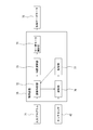
- the machine tool 11 includes a control device 70.
- the control device 70 includes a reading / interpreting unit 72, an interpolation calculation unit 73, and a servomotor control unit 74.
- the reading / interpreting unit 72 reads the input program 71 and sends the programmed movement command to the interpolation calculation unit 73.
- the interpolation calculation unit 73 calculates the position command value for each interpolation cycle, and sends the position command value to the servomotor control unit 74. For example, the interpolation calculation unit 73 calculates the movement amount for each time interval set based on the movement command.
- the servomotor control unit 74 drives each axis servomotor 75 based on the position command value.
- the control device 70 includes a calculation unit 76 connected to the measuring device 40 described later, and a storage unit 77 connected to the reading / interpretation unit 72 and the calculation unit 76.
- a predetermined surface portion of the test work 1 (FIGS. 6 to 11) is processed before the main processing of processing the work W.
- the rotary tool 2 used for machining the test work 1 is the same rotary tool as the rotary tool T used for the main machining.
- the rotary tool 2 can be a ball end mill.
- the test work 1 has a rectangular parallelepiped shape. In the present invention, the rectangular parallelepiped shape includes a cube shape.
- the rotary table 35 is placed at the position shown in FIG. At this position, the work mounting surface 35a of the rotary table 35 is arranged perpendicular to the Z axis. This position of the rotary table 35 is referred to as a first position.
- the rotary table 35 is arranged at the second position shown in FIG.
- the work mounting surface 35a of the rotary table 35 is arranged perpendicular to the work mounting surface 35a of the rotary table 35 at the first position, parallel to the Z axis, which is one of the three orthogonal axes, and The other axis, in this embodiment, is in a position perpendicular to the Y axis.
- the B axis When the rotary table 35 is in the first position, the B axis is in the rotation position of 0 ° (zero degree). When the B axis is 0 ° and the C axis is in the rotation position of 0 °, the rotary table 35 is said to be in the first posture. That is, when the rotary table 35 is in the first posture, both the B axis and the C axis are in the origin position. When the rotary table 35 is fed 180 ° toward the second position as shown by the arrow 105 without rotating the C axis from the first posture, the rotary table 35 has a B axis of 180 °. The C axis moves to the rotation position of 0 °. This rotation position is set as the second posture of the rotary table 35.
- the rotation position when the C-axis is rotated by 90 ° is set as the third posture of the rotary table 35, and the rotation position when the C-axis is further rotated by 90 ° is the fourth posture of the rotary table 35.
- the posture and the rotation position when the C axis is further rotated by 90 ° are set as the fifth posture of the rotary table 35.
- the two opposing side surfaces are perpendicular to the X axis, and the other two opposite side surfaces are perpendicular to the Y axis. Is placed in.
- one side surface (upper surface) of the test work mounted on the work mounting surface 35a is perpendicular to the Z axis, which is one of the three orthogonal axes, and faces the rotary tool 2.
- the upper surface facing the rotary tool 2 has two surface portions 1-1 and 1-2 to be tested. Further, in the test work 1, each of the four side surfaces vertically connected to the upper surface having the two surface portions 1-1 and 1-2 should also be tested and processed by the rotary tool 2. It has 3, 1-7; 1-4, 1-8; 1-5, 1-9; 1-6, 1-10.
- the two surface portions 1-1 and 1-2 on the upper surface can be rectangular, preferably square, and preferably rectangular, including one ridge (edge) of the rectangular parallelepiped test work 1. Can be done.
- the two surface portions of each of the four sides connected to the top surface can have a rectangular or strip shape of constant width.
- the rotary table 35 is placed in the first posture, and one of the two surface portions on the upper surface of the test work 1 is linearly fed with the rotary table 35 in the three orthogonal axes (X-axis, Y-axis, Z-axis). At the same time, it is processed by the tip of the rotary tool 2.
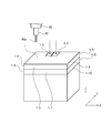
- the upper surface portion 1 that is, the surface portion 1 adjacent to the upper surface of the test work 1.
- -3, 1-4, 1-5, 1-6 are machined on the side surface of the rotary tool 2 as shown in FIG.
- the machining mode by linear feed in the orthogonal three-axis (X-axis, Y-axis, Z-axis) direction is referred to as three-axis machining.
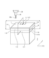
- the rotary table 35 is then rotationally fed in the B-axis direction to the second position ( It is arranged in FIG. 4). At this time, one of the side surfaces of the test work 1 is arranged perpendicular to the Z axis and faces the rotary tool 2. Next, the rotary table 35 is rotated 180 ° in the C-axis direction, and as shown in FIG. 8, the two surface portions 1-1 and 1-2 to be machined on the upper surface are arranged on the upper side, that is, closer to the rotary tool 2. do. At this time, the rotary table 35 is arranged in the fourth posture.
- the rotary table 35 With the rotary table 35 arranged at this position in the fourth posture, the rotary table 35 is linearly fed in the three orthogonal axes (X-axis, Y-axis, Z-axis) to perform test processing on the upper surface of the test work 1.
- the other 1-2 of the surface portion is machined on the side surface of the rotary tool 2.
- the processing parameters of the surface portion 1-1 and the surface portion 1-2 are set so as to be a processed surface having no step in the processing program.
- the other surface portion 1-7 of the two surface portions to be machined on each of the four side surfaces connected perpendicularly to the upper surface of the test work 1 is formed by the tip of the rotary tool 2. Process.
- the C-axis is rotated by 90 °, the rotary table 35 is arranged in the fifth posture, and the surface portion 1-8 is machined with the tip of the rotary tool 2, and the surface portion is processed.
- the C-axis is further rotated by 90 °, the rotary table 35 is placed in the second posture, and the surface portion 1-9 is machined with the tip of the rotary tool 2.
- the surface portion When the machining of 1-9 is completed, the C-axis is further rotated by 90 °, the rotary table 35 is arranged in the third posture, and the surface portion 1-10 is machined with the tip of the rotary tool 2.
- the machining mode by linear feed in the orthogonal three axes (X-axis, Y-axis, Z-axis) direction and rotary feed by two rotary feed axes (B-axis, C-axis) is referred to as 5-axis machining.
- Surface part 1-3 and surface part 1-7, surface part 1-4 and surface part 1-8, surface part 1-5 and surface part 1-9, surface part 1-6 and surface part 1-10 are processed.
- machining parameters are set so that the machined surface has no steps.
- the rotary table 35 is placed in the first posture.
- the upper surface of the test work 1 is arranged perpendicular to the Z axis, and two of the four side surfaces connected perpendicularly to the upper surface.
- the surface portions 1-3, 1-7 and the surface portion 1 The side surfaces with -5 and 1-9 are arranged perpendicular to the Y axis, and the side surfaces with surface portions 1-4 and 1-8 and surface portions 1-6 and 1-10 are arranged perpendicular to the X axis.
- NS the rotary tool 2 is removed from the spindle 25, and the measuring device 40 is attached to the spindle 25 instead.
- the measuring device 40 can be a touch sensor that outputs a signal when the measuring probe 40a comes into contact with the surface of the object to be measured.
- the measuring probe 40a of the measuring device 40 is placed above each of the two surface portions 1-1 and 1-2 on the upper surface of the test work 1, and is used for testing along the Z axis.
- the Z coordinates Z 1-1 and Z 1-2 of the two surface portions 1-1 and 1-2 are measured. That is, the measuring device 40 sends a signal in which the measuring probe 40a comes into contact with each of the surface portions 1-1 and 1-2 to the calculation unit 76, and the calculation unit 76 causes the measurement probe 40a to send the measurement bulb 44 surface portion 1-.
- the Z coordinate at the time of contact with each of 1, 1-2 is detected and stored in the storage unit 77.
- the surface portions 1-3, 1-4, 1-5, 1-6 of each of the four side surfaces connected to the upper surface of the test work 1 and the surface portions 1-7 The measuring probe 40a of the measuring device 40 is brought into contact with each of the surface portions by linearly feeding in a direction perpendicular to 1-8, 1-9, and 1-10.
- the calculation unit 76 detects the coordinate value at that time and stores it in the storage unit 77. More specifically, the Y coordinates Y 1-3 and Y 1-5 of the surface portions 1-3 and 1-5 and the Y coordinates Y 1-7 and Y 1-9 of the surface portions 1-7 and 1-9. , X coordinates X 1-4 , X 1-6 of surface parts 1-4, 1-6 and X coordinates X 1-8 , X 1-10 of surface parts 1-8, 1-10 are measured and stored. It is stored in the part 77.
- the coordinates (X C5 , Y C5 ) ((X 1-8 + X 1-10 ) / 2, (Y 1-7 + Y 1-9 ) / 2) of the center C5 of 6.
- the calculation result is stored in the storage unit 77.
- and the distance between surface parts 1-3, 1-5 ⁇ 3
- the difference ⁇ ⁇ 3- ⁇ 5 between the distance ⁇ 3 between the surface portions in the direction and the distance ⁇ 5 between the surface portions in the X direction by 5-axis processing is calculated, and the calculation result is stored in the storage unit 77.
- the calculation unit 76 determines the correction amount CV as follows.
- CV4 ⁇ + CV3
- CV5 (( ⁇ + CV3)) + ( ⁇ + CV4)) / 2
- CV1 is the X-direction correction amount of the rotation center of the rotary table 35
- CV2 is the Y-direction correction amount of the rotation center of the rotary table 35
- CV3 is the Z-axis correction amount
- CV4 is the tool length direction of the rotary tool 2.
- the correction amount of the tool measuring device, CV5, is the correction amount of the Z coordinate in the work coordinate system (calibration value in the Z direction of the measuring device 40).
- the measurement of the test work 1 described above can be automatically performed by inputting an automatic measurement program as an input program 71 to the control device 70.
- an automatic measurement program as an input program 71 to the control device 70.
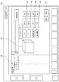
- the control device 70 executes the automatic measurement program, for example, the input screen shown in FIG. 13 is displayed on a display device such as a touch panel attached to a control panel (not shown) of the machine tool 11.
- the input screen 100 is the area 102, 104, 106 for inputting machining parameters such as dimensions in the X, Y, and Z directions and the depth of cut (depth from the surface of the test work 1) as the size of the test work 1. , 108.
- One of the areas 102, 104, 106, and 108 is activated, and a numerical value is input to each of the areas 102, 104, 106, and 108 using an input device (not shown) such as a keyboard.
- the input processing parameters of the test work 1 are stored in the storage unit 77.
- the input screen 100 can include an area 120 for displaying the machining process of the test work 1 such as the work origin check, the type of the tool to be used, and the like. Further, the approximate shape 130 of the test work 1 may be displayed.
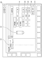
- the tool information input screen 200 shown in FIG. 14 can be displayed.
- the tool information input screen 200 includes areas for inputting tool parameters such as tool diameter, and areas 202, 204, 206, and 208 for inputting pick feed amount, spindle rotation speed, and feed speed as machining conditions.
- the input tool parameters and machining conditions are stored in the storage unit 77.
- the input screen 100 can include an area 220 for displaying the machining process of the test work 1 such as the work origin check, the type of tool to be used, and the like. Further, the approximate shape 230 of the tool used for machining the test work 1 may be displayed.
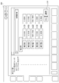
- the test work 1 described above is processed and measured, and the calculation result of the correction amount can be displayed on the correction amount display screen 300 shown in FIG.
- the operator confirms the correction amount and taps the apply button 310 to perform the processing to which the correction amount is applied in the main processing.
Landscapes
- Engineering & Computer Science (AREA)
- Mechanical Engineering (AREA)
- Human Computer Interaction (AREA)
- Manufacturing & Machinery (AREA)
- Physics & Mathematics (AREA)
- General Physics & Mathematics (AREA)
- Automation & Control Theory (AREA)
- Numerical Control (AREA)
- Machine Tool Sensing Apparatuses (AREA)
Abstract
直動送り軸と、回転送り軸とを有した工作機械(11)で主軸(25)に取り付けた回転工具(T)と回転テーブル(35)に固定したワーク(W)とを相対的に移動して加工を行う加工方法において、回転テーブル上に試験用ワーク(1)を固定し、試験用ワークを複数の姿勢に位置決めして、ワークの本加工時に用いる回転工具(2)で試験用ワークの表面の所定部分を加工し、試験用ワークの加工した各表面部分を測定し、測定した結果に基づいて、回転送り軸の誤差を機械座標系に対する回転テーブルの回転中心の位置情報および回転工具の工具長の補正量で補正する。
Description
本発明は、直交3軸の直線送り軸に加えて、回転送り軸を有した工作機械による加工方法に関する。
例えば5軸のマシニングセンタのような回転送り軸を有した工作機械では、回転送り軸の回転軸線の位置誤差等により高精度に加工することができない。特許文献1には、こうした工作機械の回転送り軸の回転軸線の位置誤差や傾斜誤差を演算する方法が記載されている。
特許文献1に記載の方法では、ワークテーブルを主軸に対して相対回転させて少なくとも回転角度の異なる3箇所の測定位置に位置決めし、ワークテーブル上に配設された基準球の中心位置を主軸に装着したタッチセンサにより測定し、それぞれの測定位置において測定された基準球の中心位置に基づき、回転軸の方向ベクトルを算出して、回転軸の基準方向ベクトルに対する実際の方向ベクトルの傾き誤差を算出するようになっている。
特許文献1に記載の方法では、クーラントや主軸を停止する等、実際の加工とは異なる条件、環境下で測定を行っているので、測定結果を反映させて加工したときに、実際の加工精度がどうなるのか分からないまま実際の加工(本加工)をすることになる。
本発明は、こうした従来技術の問題を解決することを技術課題としており、回転送り軸の回転軸線が、位置誤差や傾斜誤差、振れ誤差を有していても、高精度にワークを加工できる加工方法を提供することを目的としている。
上述の目的を達成するために、本発明によれば、直動送り軸と、回転送り軸とを有した工作機械で、主軸に取り付けた回転工具と回転テーブルに固定したワークとを相対的に移動して加工を行う加工方法において、前記回転テーブル上に試験用ワークを固定し、前記試験用ワークを複数の姿勢に位置決めして、ワークの本加工時に用いる回転工具で前記試験用ワークの表面の所定部分を加工し、前記試験用ワークの加工した各表面部分を測定し、前記測定した結果に基づいて、前記回転送り軸の誤差を機械座標系に対する前記回転テーブルの回転中心の位置情報および前記回転工具の工具長の補正量で補正し、前記ワークを加工するようにした加工方法が提供される。
本発明によれば、試験用ワークの所定の表面部分を、実際の加工(本加工)と同じ条件、環境下で本加工の前に加工し、該表面部分を測定して、回転軸の中心を求める、それに基づいて補正量を演算により求めることにより、回転送り軸の回転軸線が、位置誤差や傾斜誤差、振れ誤差を有していても、高精度にワークを加工可能となる。
以下、添付図面を参照して、本発明の好ましい実施形態を説明する。
まず、図1、2を参照して、本発明適用する工作機械の一例を説明する。
図1、2において、工作機械11は、基台となるベッド13と、ベッド13の上面に立設されたコラム15とを備える。ベッド13の上面には、移動体27が配置されている。移動体27は、傾斜旋回台28を介してワークWを回転させる回転テーブル35を支持している。回転テーブル35は、ワークWを固定するワーク取付面35aを有している。
まず、図1、2を参照して、本発明適用する工作機械の一例を説明する。
図1、2において、工作機械11は、基台となるベッド13と、ベッド13の上面に立設されたコラム15とを備える。ベッド13の上面には、移動体27が配置されている。移動体27は、傾斜旋回台28を介してワークWを回転させる回転テーブル35を支持している。回転テーブル35は、ワークWを固定するワーク取付面35aを有している。
コラム15の前面には、サドル17が配置されている。さらに、サドル17の前面には、主軸ヘッド21が配置されている。主軸ヘッド21には主軸25が取り付けられている。主軸25には、ワークWを加工する回転工具Tが取り付けられる。回転工具Tは、主軸25と共に回転しながらワークWを加工する。
本実施の形態における工作機械11は、回転工具TとワークWとの相対位置を変更する移動装置を備えている。本実施の形態においては、工作機械における所定の位置を原点とした機械座標系が設定されている。機械座標系について互いに直交するX軸、Y軸およびZ軸が予め定められている。工作機械の設計時において、主軸25の軸線が延びる方向(図1において上下方向)をZ軸と称する。また、移動体27が移動する水平方向に延びる軸をY軸と称する。また、サドル17が移動する水平方向、すなわちZ軸およびY軸に垂直な方向に延びる軸をX軸と称する。
移動装置は、X軸方向、Y軸方向およびZ軸方向に回転工具TとワークWとを相対的に移動させることができる。さらに、移動装置は、傾斜旋回台28の軸線52の周りのB軸方向および回転テーブル35の軸線53の周りのC軸方向に、回転工具Tに対してワークWを相対的に回転移動させることができる。
移動装置は、ワークWに対して回転工具TをX軸方向に相対移動させるX軸移動装置を含む。X軸移動装置は、コラム15の前面に形成されている一対のX軸レール19a、19bを含む。サドル17は、X軸レール19a、19bに沿って往復移動が可能に形成されている。X軸移動装置は、ボールねじ機構によりサドル17を移動する。X軸移動装置は、ボールねじ機構のねじ軸を回転させるX軸サーボモータ20を含む。X軸移動装置は、X軸サーボモータ20を駆動することにより、サドル17を移動させる。主軸ヘッド21および回転工具Tは、サドル17と共にX軸方向に移動する。
移動装置は、ワークWに対して回転工具TをZ軸方向に相対移動させるZ軸移動装置を含む。Z軸移動装置は、サドル17の前面に形成されている一対のZ軸レール23a、23bを含む。主軸ヘッド21は、Z軸レール23a、23bに沿って往復移動が可能に形成されている。Z軸移動装置は、ボールねじ機構により主軸ヘッド21を移動する。Z軸移動装置は、ボールねじ機構のねじ軸を回転させるZ軸サーボモータ24を含む。Z軸移動装置は、Z軸サーボモータ24を駆動することにより、主軸ヘッド21を移動させる。回転工具Tは、主軸ヘッド21と共にZ軸方向に移動する。更に、主軸ヘッド21の内部には、主軸25を軸線周りに回転する駆動モータが配置されている。
図3に、本実施の形態の形態におけるY軸移動装置の概略斜視図を示す。図1から図3を参照して、移動装置は、ワークWに対して回転工具TをY軸方向に相対移動させるY軸移動装置を含む。Y軸移動装置は、ベッド13の上面に配置されている一対のY軸レール29a、29bを含む。移動体27は、Y軸レール29a、29bに沿って往復移動が可能に形成されている。コラム15には、移動体27がY軸方向に移動可能なように空洞部15aが形成されている。
Y軸移動装置は、ボールねじ機構30により移動体27を移動させる。Y軸移動装置は、ボールねじ機構のねじ軸を回転させるY軸サーボモータ32を含む。Y軸移動装置は、Y軸サーボモータ32を駆動することにより、移動体27を移動させる。傾斜旋回台28および回転テーブル35は、移動体27と共にY軸方向に移動する。
移動装置は、ワークWに対して回転工具TをB軸方向に相対的に回転させるB軸回転移動装置を含む。本実施の形態におけるB軸の軸線52は、X軸、Y軸およびZ軸のいずれの軸に対しても平行ではない。すなわち、B軸の軸線52は、3つの直動軸のそれぞれの軸に対して傾斜している。B軸回転移動装置は、傾斜旋回台28を含む。移動体27の内部には、傾斜旋回台28を回転させるためのサーボモータが配置されている。傾斜旋回台28のサーボモータを駆動することにより、B軸の軸線52の周りに傾斜旋回台28が回転する。ワークWは、傾斜旋回台28および回転テーブル35と共にB軸方向に回転する。
本実施の形態における移動装置は、ワークWに対して回転工具TをC軸方向に相対的に回転させるC軸回転移動装置を含む。傾斜旋回台28がB軸方向の予め定められた角度位置にあるときに、C軸の軸線53がZ軸と平行になるように設計されている。C軸回転移動装置は、回転テーブル35を含む。傾斜旋回台28の内部にはサーボモータが配置されている。このサーボモータを駆動することにより、C軸の軸線53の周りに回転テーブル35が回転する。ワークWは、回転テーブル35と共にC軸方向に回転する。
このように、工作機械11は、ワークWに対して主軸25が相対的に移動する3つの直動軸を有する。すなわち、工作機械11は、直動軸としてのX軸、Y軸およびZ軸を有する。本実施の形態では、第1直動軸をY軸、第2直動軸をZ軸、および第3直動軸をX軸として説明する。また、工作機械11は、ワークWに対して主軸25が相対的に回転移動する2つの回転軸を有する。すなわち、工作機械11は、回転軸としてのB軸の軸線52およびC軸の軸線53を有する。本実施の形態では、第1回転方向をC軸方向とし、第2回転方向をB軸方向として説明する。また、第1軸線をC軸の軸線53とし、第2軸線をB軸の軸線52として説明する。
本実施の形態における工作機械は、制御装置70を備える。制御装置70は、移動装置のサーボモータや駆動モータに接続されている。制御装置70は、移動装置のサーボモータを制御することによりワークWに対して回転工具Tを相対的に移動させることができる。
図1、2を参照して、工作機械11は、それぞれの回転軸に関する回転角度が0°の時に、回転テーブル35の表面が機械座標系のX軸とY軸とを含む平面、すなわちXY平面と厳密に平行になり、かつ、B軸の軸線52とC軸の軸線53とが交差するように製造することが好ましい。しかしながら製造誤差や経年変化等により、回転テーブル35の表面が僅かに傾いたり、軸線52と軸線53とが僅かに離れたりする場合がある。
工作機械11は、移動体27の傾きを調整する調整手段として角度調整装置を備える。本実施の形態においては、移動体27のY軸ストロークに渡って、YZ平面に対してB軸の軸線52およびC軸の軸線53が平行に延びるように、移動体27の傾きを調整する。本実施の形態においては、移動体27をY軸方向に移動している期間中に、YZ平面に対してB軸の軸線52およびC軸の軸線53がそれぞれ平行に延びる状態を基準状態と称する。
また、工作機械11は、制御装置70を備える。制御装置70は、読取解釈部72、補間演算部73、およびサーボモータ制御部74を含む。読取解釈部72は、入力プログラム71を読取って、プログラムされた移動指令を補間演算部73に送出する。補間演算部73は、補間周期毎の位置指令値を演算し、位置指令値をサーボモータ制御部74に送出する。たとえば、補間演算部73は、移動指令に基づいて設定された時間間隔ごとの移動量を算出する。サーボモータ制御部74は、位置指令値に基づいて各軸サーボモータ75を駆動する。また、制御装置70は、後述する測定装置40に接続された演算部76と、読取解釈部72および演算部76に接続された記憶部77を備えている。
以下、図3~図8を参照して、本発明の作用を説明する。
本発明では、ワークWを加工する本加工の前に試験用ワーク1(図6~図11)の所定の表面部分を加工する。このとき、試験用ワーク1を加工するために用いる回転工具2は、本加工するときに用いる回転工具Tと同じ回転工具である。回転工具2は、ボールエンドミルとすることができる。試験用ワーク1は、直方体形状を有している。本発明では、直方体形状は立方体形状を含む。
本発明では、ワークWを加工する本加工の前に試験用ワーク1(図6~図11)の所定の表面部分を加工する。このとき、試験用ワーク1を加工するために用いる回転工具2は、本加工するときに用いる回転工具Tと同じ回転工具である。回転工具2は、ボールエンドミルとすることができる。試験用ワーク1は、直方体形状を有している。本発明では、直方体形状は立方体形状を含む。
まず、試験用ワーク1の加工に先立ち、回転テーブル35を図3に示す位置に配置する。この位置において、回転テーブル35のワーク取付面35aは、Z軸に垂直に配置される。回転テーブル35のこの位置を第1の位置と称する。第1の位置から回転テーブル35を矢印105で示すようにB軸方向に180°送ることによって、回転テーブル35は、図4に示す第2の位置に配置される。このとき、回転テーブル35のワーク取付面35aは第1の位置にある回転テーブル35のワーク取付面35aに対して垂直に配置で、直交3軸の1つであるZ軸に平行で、かつ、他の軸、本実施形態では、Y軸に対して垂直な位置にある。
回転テーブル35が第1の位置にあるときB軸は0°(零度)の回転位置にある。B軸が0°で、かつ、C軸が0°の回転位置にあるとき、回転テーブル35は第1の姿勢にあると称する。つまり、回転テーブル35が第1の姿勢にあるときB軸およびC軸の双方が原点位置にある。回転テーブル35を第1の姿勢からC軸を回転させることなく、B軸のみを矢印105で示すように第2の位置へ向けて180°送ると、回転テーブル35は、B軸は180°でC軸が0°の回転位置へ移動する。この回転位置を回転テーブル35の第2の姿勢とする。
第2の姿勢から、C軸を90°回転させたときの回転位置を回転テーブル35の第3の姿勢とし、C軸を更に90°回転させたときの回転位置を回転テーブル35の第4の姿勢、C軸を更に90°回転させたときの回転位置を回転テーブル35の第5の姿勢とする。
試験用ワーク1は、第1の姿勢にある回転テーブル35のワーク取付面35a上において、対向する2つの側面がX軸に垂直に、他の対向する2つの側面がY軸に垂直になるように配置される。このとき、ワーク取付面35aに取り付けられた試験用ワークの1つの側面(上面)は、直交3軸の1つの軸であるZ軸に垂直となり、かつ、回転工具2に対面する。
この回転工具2に対面する上面は、試験加工すべき2つの表面部分1-1、1-2を有している。また、試験用ワーク1において、この2つの表面部分1-1、1-2を有した上面に垂直に接続する4つの側面の各々も、回転工具2により試験加工すべき2つの表面部分1-3、1-7;1-4、1-8;1-5、1-9;1-6、1-10を有している。上面の2つの表面部分1-1、1-2は、矩形、好ましくは正方形とすることができ、好ましくは、直方体形状の試験用ワーク1の1つの稜線(エッジ)を含む矩形状とすることができる。上面に接続する4つの側面の各々の2つの表面部分は、一定幅の長方形または帯状の形状とすることができる。
先ず、回転テーブル35を第1の姿勢に配置し、試験用ワーク1の上面の2つの表面部分の一方を、回転テーブル35を直交3軸(X軸、Y軸、Z軸)方向に直線送りつつ、回転工具2の先端により加工する。次に、試験用ワーク1の上面に垂直に接続する4つの側面の各々において加工すべき2つの表面部分の一方、本実施形態では、上側、つまり試験用ワーク1の上面に隣接する表面部分1-3、1-4、1-5、1-6を、図7に示すように、回転工具2の側面で加工する。このように、直交3軸(X軸、Y軸、Z軸)方向の直線送りよる加工モードを3軸加工と称する。
回転工具2の側面で4つの側面の表面部分1-3、1-4、1-5、1-6を加工すると、次いで、回転テーブル35をB軸方向に回転送りして第2の位置(図4)に配置する。このとき、試験用ワーク1の側面の1つが、Z軸に垂直に配置され、かつ、回転工具2に対面する。次いで、回転テーブル35をC軸方向に180°回転し、図8に示すように、上面において加工すべき2つの表面部分1-1、1-2が上側、つまり回転工具2に近い方に配置する。このとき、回転テーブル35は第4の姿勢に配置される。
回転テーブル35を第4の姿勢におけるこの位置に配置した状態で、直交3軸(X軸、Y軸、Z軸)方向に直線送りして、試験用ワーク1の上面の試験加工すべき2つの表面部分の他方1-2を回転工具2の側面で加工する。このとき、表面部分1-1と表面部分1-2は、加工プログラム上では、段差のない加工面となるように、加工パラメータが設定されている。次に、試験用ワーク1の上面に垂直に接続する4つの側面の各々において加工すべき2つの表面部分の他方の表面部分1-7を、図9に示すように、回転工具2の先端で加工する。
次いで、表面部分1-7の加工が完了したときC軸を90°回転させ、回転テーブル35を第5の姿勢に配置して表面部分1-8を回転工具2の先端で加工し、表面部分1-8の加工が完了したときC軸を更に90°回転させ、回転テーブル35を第2の姿勢に配置して表面部分1-9を回転工具2の先端で加工し、同様に、表面部分1-9の加工が完了したときC軸を更に90°回転させ、回転テーブル35を第3の姿勢に配置して表面部分1-10を回転工具2の先端で加工する。このように、直交3軸(X軸、Y軸、Z軸)方向の直線送りと、2つの回転送り軸(B軸、C軸)による回転送りによる加工モードを5軸加工と称する。表面部分1-3と表面部分1-7、表面部分1-4と表面部分1-8、表面部分1-5と表面部分1-9、表面部分1-6と表面部分1-10は、加工プログラム上では、段差のない加工面となるように、加工パラメータが設定されている。
こうして、全ての加工すべき表面部分の加工が完了した後、回転テーブル35を第1の姿勢に配置する。このとき、試験用ワーク1の上面がZ軸に垂直に配置され、上面に垂直に接続する4つの側面のうち2つの側面、図9では、表面部分1-3、1-7と表面部分1-5、1-9を有した側面がY軸に垂直に配置され、表面部分1-4、1-8と表面部分1-6、1-10を有した側面がX軸に垂直に配置される。また、これと同時に、回転工具2を主軸25から取り外し、代わりに測定装置40が主軸25に装着される。測定装置40は、測定プローブ40aが測定対象物の表面に接触したときに、信号を出力するタッチセンサとすることができる。
次いで、図10に示すように、測定装置40の測定プローブ40aを試験用ワーク1の上面の2つの表面部分1-1、1-2の各々の上方に配置し、Z軸に沿って試験用ワーク1に接近させることによって、2つの表面部分1-1、1-2の各々のZ座標Z1-1、Z1-2が測定される。つまり、測定装置40は、測定プローブ40aが表面部分1-1、1-2の各々に接触した信号を演算部76に送出し、演算部76は、測定プローブ40aが測定球44表面部分1-1、1-2の各々に接触した時のZ座標を検出し、記憶部77に記憶させる。
次いで、図11に示すように、試験用ワーク1の上面に接続された4つの側面の各々の表面部分1-3、1-4、1-5、1-6と、表面部分1-7、1-8、1-9、1-10に対して垂直な方向に直線送りして、測定装置40の測定プローブ40aを該表面部分の各々に接触させる。同様に、演算部76は、その時の座標値を検出し、記憶部77に記憶させる。より詳細には、表面部分1-3、1-5のY座標Y1-3、Y1-5と、表面部分1-7、1-9のY座標Y1-7、Y1-9と、表面部分1-4、1-6のX座標X1-4、X1-6と、表面部分1-8、1-10のX座標X1-8、X1-10が測定され、記憶部77に記憶される。
測定結果に基づき、演算部76は、3軸加工により加工された表面部分1-3、1-4、1-5、1-6の中心C3の座標(XC3, YC3)=((X1-4+X1-6)/2,(Y1-3+Y1-5)/2)、および、5軸加工により加工された表面部分1-3、1-4、1-5、1-6の中心C5の座標(XC5, YC5)=((X1-8+X1-10)/2,(Y1-7+Y1-9)/2)を演算する。次いで、演算部76は、3軸加工による中心C3に対する5軸加工による中心C5のX方向の偏差α=((X1-4+X1-6)/2)-((X1-8+X1-10)/2)およびY方向の偏差β=((Y1-3+Y1-5)/2)-((Y1-7+Y1-9)/2)を演算する。演算結果は記憶部77に記憶される。
次いで、演算部76は、3軸加工により加工された表面部分1-3、1-4、1-5、1-6のX方向およびY方向の距離、つまり表面部分1-4、1-6間の距離γ3=|X1-4-X1-6|および表面部分1-3、1-5間の距離δ3=|Y1-3-Y1-5|を演算し、そして5軸加工により加工された表面部分1-7、1-8、1-9、1-10のX方向およびY方向の距離、つまり表面部分1-8、1-10間の距離γ5=|X1-8-X1-10|および表面部分1-7、1-9間の距離δ5=|Y1-7-Y1-9|を演算し、演算結果は記憶部77に記憶される。
次いで、演算部76は、3軸加工によるX方向の表面部分間の距離γ3と、5軸加工によるX方向の表面部分間の距離γ5との差分γ=γ3-γ5と、5軸加工によるY方向の表面部分間の距離δ3と、5軸加工によるX方向の表面部分間の距離δ5との差分δ=δ3-δ5とを演算し、演算結果を記憶部77に記憶する。更に、演算部76は、X方向の表面部分間の距離およびY方向の表面部分間の距離に関して3軸加工と5軸加工の差分の平均値λ=(γ+δ)/4を演算し、演算結果を記憶部77に記憶する。
次いで、演算部76は、試験用ワーク1の3軸加工により加工された表面部分1-1のZ方向の目標値Hzと測定値であるZ座標Z1-1との差分ε=Z1-1-Hz、および、試験用ワーク1の5軸加工により加工された表面部分1-2のZ方向の目標値Hzと測定値であるZ座標Z1-2との差分ζ=Z1-2-Hzを演算し、演算結果は記憶部77に記憶される。
更に、演算部76は、試験用ワーク1のX方向の目標値Lxと、3軸加工によるX方向の表面部分間の距離γ3との差分Dx=Lx-γ3、および、Y方向の目標値Lyと、Y方向の表面部分間の距離δ3との差分Dy=Ly-δ3を演算する。演算部76は、は、更に、その平均値η=(Dx+Dy)/4を演算して、演算結果を記憶部77に記憶する。
上記演算結果に基づき、演算部76は、以下のように補正量CVを決定する。
CV1=α
CV2=β
CV3=-(ζ+η)/2
CV4=λ+CV3
CV5=((ζ+CV3))+(ε+CV4))/2
CV1=α
CV2=β
CV3=-(ζ+η)/2
CV4=λ+CV3
CV5=((ζ+CV3))+(ε+CV4))/2
ここで、CV1は回転テーブル35の回転中心のX方向補正量、CV2は回転テーブル35の回転中心のY方向補正量、CV3はZ軸補正量、CV4は回転工具2の工具長さ方向への工具測定装置の補正量、CV5はワーク座標系におけるZ座標の補正量(測定装置40のZ方向のキャリブレーション値)である。
既述の試験用ワーク1の測定は、制御装置70に入力プログラム71として、自動測定プログラムを入力することによって、自動的に行うことができる。制御装置70が自動測定プログラムを実行すると、例えば、工作機械11の制御盤(図示せず)に取り付けてあるタッチパネルのような表示装置に図13に示す入力画面が表示される。
入力画面100は、試験用ワーク1のサイズとしてX方向、Y方向、Z方向の寸法および切込み量(試験用ワーク1の表面からの深さ)等の加工パラメータを入力する領域102、104、106、108を備えている。この領域102、104、106、108の1つをアクティブにして、キーボード等の入力装置(図示せず)を用いて各領域102、104、106、108に数値を入力する。入力された試験用ワーク1の加工パラメータは記憶部77に記憶される。なお、入力画面100には、ワーク原点チェックのような試験用ワーク1の加工工程、使用する工具の種類等を表示する領域120を含むことができる。更に、試験用ワーク1の概略形状130を表示するようにしてもよい。
入力が完了した後に進むボタン110をタップことによって、図14に示す工具情報入力画面200を表示するようにできる。工具情報入力画面200は、工具径のような工具パラメータを入力する領域、加工条件としてピックフィード量、主軸回転速度および送り速度を入力する領域202、204、206、208を備えている。入力された工具パラメータや加工条件は記憶部77に記憶される。なお、入力画面100には、ワーク原点チェックのような試験用ワーク1の加工工程、使用する工具の種類等を表示する領域220を含むことができる。更に、試験用ワーク1を加工するために使用される工具の概略形状230を表示するようにしてもよい。
入力が完了した後に進むボタン210をタップことによって、既述した試験用ワーク1の加工および測定が行われ、補正量の演算結果を図15に示す補正量表示画面300に表示するようにできる。オペレーターは補正量を確認して、適用ボタン310をタップすることによって、本加工に際して補正量を適用した加工が行われる。
1 試験用ワーク
1-1 表面部分
1-10 表面部分
1-2 表面部分
1-3 表面部分
1-4 表面部分
1-5 表面部分
1-6 表面部分
1-7 表面部分
1-8 表面部分
1-9 表面部分
2 回転工具
11 工作機械
13 ベッド
15 コラム
17 サドル
19a X軸レール
19b X軸レール
21 主軸ヘッド
23a Z軸レール
23b Z軸レール
25 主軸
27 移動体
28 傾斜旋回台
29a Y軸レール
29b Y軸レール
35 回転テーブル
35a ワーク取付面
40 測定装置
40a 測定プローブ
52 軸線
53 軸線
70 制御装置
71 入力プログラム
72 読取解釈部
73 補間演算部
74 サーボモータ制御部
75 軸サーボモータ
76 演算部
77 記憶部
100 入力画面
200 工具情報入力画面
300 補正量表示画面
C3 中心
C5 中心
CV 補正量
Dx 差分
Dy 差分
Hz 目標値
Lx 目標値
Ly 目標値
T 回転工具
W ワーク
α 偏差
β 偏差
γ 差分
γ3 距離
γ5 距離
δ 差分
δ3 距離
δ5 距離
ε 差分
ζ 差分
η 平均値
λ 平均値
Claims (5)
- 直動送り軸と、回転送り軸とを有した工作機械で、主軸に取り付けた回転工具と回転テーブルに固定したワークとを相対的に移動して加工を行う加工方法において、
前記回転テーブル上に試験用ワークを固定し、
前記試験用ワークを複数の姿勢に位置決めして、ワークの本加工時に用いる回転工具で前記試験用ワークの表面の所定部分を加工し、
前記試験用ワークの加工した各表面部分を測定し、
前記測定した結果に基づいて、前記回転送り軸の誤差を機械座標系に対する前記回転テーブルの回転中心の位置情報および前記回転工具の工具長の補正量で補正し、
前記ワークを加工することを特徴とした加工方法。 - 前記工作機械は、直交3軸の直線送り軸と、該直交3軸の1つに平行な軸線周りの回転送り軸と、該回転送り軸の軸線と異なる軸線周りの回転送り軸とを有し、
前記試験用ワークは直方体形状を有しており、前記試験用ワークの表面の加工すべき所定部は、該試験用ワークの1つの表面を前記直交3軸の1つに対して垂直に向けたときに、前記回転工具の先端に対面する表面に2つの部分と、該表面に接続する4つの側面の各々に2つの部分とを含む請求項1に記載の加工方法。 - 前記回転工具に対面する表面の2つの加工すべき表面部分の一方を前記回転工具の先端で加工し、他方を前記回転工具の側面で加工する請求項2に記載の加工方法。
- 前記回転工具に対面する表面に接続する4つの側面の各々の2つの加工すべき表面部分の一方を前記回転工具の先端で加工し、他方を前記回転工具の側面で加工する請求項3に記載の加工方法。
- 前記回転工具はボールエンドミルである請求項1~4の何れか1項に記載の加工方法。
Priority Applications (2)
| Application Number | Priority Date | Filing Date | Title |
|---|---|---|---|
| CN202180024793.9A CN115516389A (zh) | 2020-04-10 | 2021-04-09 | 加工方法 |
| EP21784255.8A EP4134762A4 (en) | 2020-04-10 | 2021-04-09 | MACHINING PROCESS |
Applications Claiming Priority (2)
| Application Number | Priority Date | Filing Date | Title |
|---|---|---|---|
| JP2020071116A JP7026718B2 (ja) | 2020-04-10 | 2020-04-10 | 加工方法 |
| JP2020-071116 | 2020-04-10 |
Publications (1)
| Publication Number | Publication Date |
|---|---|
| WO2021206172A1 true WO2021206172A1 (ja) | 2021-10-14 |
Family
ID=78022519
Family Applications (1)
| Application Number | Title | Priority Date | Filing Date |
|---|---|---|---|
| PCT/JP2021/015080 WO2021206172A1 (ja) | 2020-04-10 | 2021-04-09 | 加工方法 |
Country Status (4)
| Country | Link |
|---|---|
| EP (1) | EP4134762A4 (ja) |
| JP (1) | JP7026718B2 (ja) |
| CN (1) | CN115516389A (ja) |
| WO (1) | WO2021206172A1 (ja) |
Cited By (1)
| Publication number | Priority date | Publication date | Assignee | Title |
|---|---|---|---|---|
| CN116000652A (zh) * | 2023-03-22 | 2023-04-25 | 北京博鲁斯潘精密机床有限公司 | 一种航空发动机叶片高刚度高精度五轴联动加工数控机床 |
Citations (6)
| Publication number | Priority date | Publication date | Assignee | Title |
|---|---|---|---|---|
| JP2005061834A (ja) | 2003-08-08 | 2005-03-10 | Toyoda Mach Works Ltd | 回転軸を有する加工機の誤差算出方法 |
| WO2009057229A1 (ja) * | 2007-11-02 | 2009-05-07 | Makino Milling Machine Co., Ltd. | エラーマップ作成方法及び装置並びにエラーマップ作成機能を有した数値制御工作機械 |
| WO2012101742A1 (ja) * | 2011-01-24 | 2012-08-02 | 三菱電機株式会社 | 誤差測定装置及び誤差測定方法 |
| WO2017130412A1 (ja) * | 2016-01-29 | 2017-08-03 | 株式会社ニコン | 加工装置の補正方法および加工装置 |
| KR20190002099A (ko) * | 2017-06-29 | 2019-01-08 | 현대위아 주식회사 | 5축 가공장치의 피봇 교정 방법 |
| JP2019040586A (ja) * | 2017-08-28 | 2019-03-14 | ファナック株式会社 | 評価用ワーク、加工プログラム及びデータ構造 |
-
2020
- 2020-04-10 JP JP2020071116A patent/JP7026718B2/ja active Active
-
2021
- 2021-04-09 EP EP21784255.8A patent/EP4134762A4/en active Pending
- 2021-04-09 CN CN202180024793.9A patent/CN115516389A/zh active Pending
- 2021-04-09 WO PCT/JP2021/015080 patent/WO2021206172A1/ja unknown
Patent Citations (6)
| Publication number | Priority date | Publication date | Assignee | Title |
|---|---|---|---|---|
| JP2005061834A (ja) | 2003-08-08 | 2005-03-10 | Toyoda Mach Works Ltd | 回転軸を有する加工機の誤差算出方法 |
| WO2009057229A1 (ja) * | 2007-11-02 | 2009-05-07 | Makino Milling Machine Co., Ltd. | エラーマップ作成方法及び装置並びにエラーマップ作成機能を有した数値制御工作機械 |
| WO2012101742A1 (ja) * | 2011-01-24 | 2012-08-02 | 三菱電機株式会社 | 誤差測定装置及び誤差測定方法 |
| WO2017130412A1 (ja) * | 2016-01-29 | 2017-08-03 | 株式会社ニコン | 加工装置の補正方法および加工装置 |
| KR20190002099A (ko) * | 2017-06-29 | 2019-01-08 | 현대위아 주식회사 | 5축 가공장치의 피봇 교정 방법 |
| JP2019040586A (ja) * | 2017-08-28 | 2019-03-14 | ファナック株式会社 | 評価用ワーク、加工プログラム及びデータ構造 |
Non-Patent Citations (1)
| Title |
|---|
| See also references of EP4134762A4 |
Cited By (1)
| Publication number | Priority date | Publication date | Assignee | Title |
|---|---|---|---|---|
| CN116000652A (zh) * | 2023-03-22 | 2023-04-25 | 北京博鲁斯潘精密机床有限公司 | 一种航空发动机叶片高刚度高精度五轴联动加工数控机床 |
Also Published As
| Publication number | Publication date |
|---|---|
| JP2021168043A (ja) | 2021-10-21 |
| CN115516389A (zh) | 2022-12-23 |
| EP4134762A4 (en) | 2024-04-17 |
| JP7026718B2 (ja) | 2022-02-28 |
| EP4134762A1 (en) | 2023-02-15 |
Similar Documents
| Publication | Publication Date | Title |
|---|---|---|
| JP5705283B2 (ja) | 工作機械および工作機械の回転軸の測定方法 | |
| US10209107B2 (en) | Geometric error identification method of multi-axis machine tool and multi-axis machine tool | |
| US10118227B2 (en) | Machine tool and workpiece flattening method | |
| KR101158772B1 (ko) | 수치제어 공작기계 및 수치제어 장치 | |
| JP2007044802A (ja) | 多軸工作機械における旋回軸中心測定方法 | |
| JP5911565B2 (ja) | 工作機械の干渉判定方法および干渉判定装置 | |
| JP4276270B2 (ja) | 接触検知によるワークの基準位置設定機能を有する工作機械 | |
| JP2009012083A (ja) | 工作機械の運動誤差測定方法及び運動誤差測定装置 | |
| JP5355037B2 (ja) | 精度測定方法及び数値制御工作機械の誤差補正方法並びに誤差補正機能を有した数値制御工作機械 | |
| WO2021206172A1 (ja) | 加工方法 | |
| JP2831610B2 (ja) | 測定装置 | |
| JP2018128328A (ja) | 工作機械の幾何誤差測定方法 | |
| US11543230B2 (en) | Articulating probe | |
| JP7266511B2 (ja) | 工作機械における対象物の位置計測方法及び位置計測システム、位置計測プログラム | |
| US20230152772A1 (en) | Positional relationship measurement method and machining apparatus | |
| JP6425009B2 (ja) | 三次元測定機、及びこれを用いた形状測定方法 | |
| JP2012079358A (ja) | エラーマップ作成方法及び装置並びにエラーマップ作成機能を有した数値制御工作機械 | |
| JP2002001568A (ja) | Nc制御3次元レーザ加工機におけるレーザ加工ヘッドのパラメータ設定方法およびnc制御3次元レーザ加工機 | |
| JP2015133073A (ja) | 工作機械の制御方法 | |
| CN107830826B (zh) | 两轴摆动头系统与两轴摆动头的误差检测方法 | |
| JPH09204213A (ja) | レーザ加工方法及びレーザ加工機 | |
| JP7128333B1 (ja) | 多軸加工機および多軸加工機の回転中心測定方法 | |
| JP5740201B2 (ja) | 幾何誤差同定装置 | |
| JP6403298B1 (ja) | Nc加工装置及び加工部品の製造方法 | |
| JPH05277894A (ja) | 工作機械の主軸熱変位補正方法および装置 |
Legal Events
| Date | Code | Title | Description |
|---|---|---|---|
| 121 | Ep: the epo has been informed by wipo that ep was designated in this application |
Ref document number: 21784255 Country of ref document: EP Kind code of ref document: A1 |
|
| ENP | Entry into the national phase |
Ref document number: 2021784255 Country of ref document: EP Effective date: 20221110 |
|
| NENP | Non-entry into the national phase |
Ref country code: DE |