WO2021206172A1 - Procédé d'usinage - Google Patents
Procédé d'usinage Download PDFInfo
- Publication number
- WO2021206172A1 WO2021206172A1 PCT/JP2021/015080 JP2021015080W WO2021206172A1 WO 2021206172 A1 WO2021206172 A1 WO 2021206172A1 JP 2021015080 W JP2021015080 W JP 2021015080W WO 2021206172 A1 WO2021206172 A1 WO 2021206172A1
- Authority
- WO
- WIPO (PCT)
- Prior art keywords
- axis
- rotary
- tool
- machining
- work
- Prior art date
Links
- 238000003754 machining Methods 0.000 title claims abstract description 50
- 238000000034 method Methods 0.000 title claims abstract description 16
- 238000012360 testing method Methods 0.000 claims abstract description 56
- 238000012937 correction Methods 0.000 claims abstract description 19
- 238000005259 measurement Methods 0.000 claims abstract description 13
- 238000012545 processing Methods 0.000 claims description 21
- 230000036544 posture Effects 0.000 claims description 19
- 238000003672 processing method Methods 0.000 claims 3
- 238000003860 storage Methods 0.000 description 12
- 239000000523 sample Substances 0.000 description 6
- 238000004519 manufacturing process Methods 0.000 description 2
- 238000010079 rubber tapping Methods 0.000 description 2
- 230000032683 aging Effects 0.000 description 1
- 239000002826 coolant Substances 0.000 description 1
- 238000010586 diagram Methods 0.000 description 1
Images


Classifications
-
- G—PHYSICS
- G05—CONTROLLING; REGULATING
- G05B—CONTROL OR REGULATING SYSTEMS IN GENERAL; FUNCTIONAL ELEMENTS OF SUCH SYSTEMS; MONITORING OR TESTING ARRANGEMENTS FOR SUCH SYSTEMS OR ELEMENTS
- G05B19/00—Programme-control systems
- G05B19/02—Programme-control systems electric
- G05B19/18—Numerical control [NC], i.e. automatically operating machines, in particular machine tools, e.g. in a manufacturing environment, so as to execute positioning, movement or co-ordinated operations by means of programme data in numerical form
- G05B19/401—Numerical control [NC], i.e. automatically operating machines, in particular machine tools, e.g. in a manufacturing environment, so as to execute positioning, movement or co-ordinated operations by means of programme data in numerical form characterised by control arrangements for measuring, e.g. calibration and initialisation, measuring workpiece for machining purposes
-
- B—PERFORMING OPERATIONS; TRANSPORTING
- B23—MACHINE TOOLS; METAL-WORKING NOT OTHERWISE PROVIDED FOR
- B23Q—DETAILS, COMPONENTS, OR ACCESSORIES FOR MACHINE TOOLS, e.g. ARRANGEMENTS FOR COPYING OR CONTROLLING; MACHINE TOOLS IN GENERAL CHARACTERISED BY THE CONSTRUCTION OF PARTICULAR DETAILS OR COMPONENTS; COMBINATIONS OR ASSOCIATIONS OF METAL-WORKING MACHINES, NOT DIRECTED TO A PARTICULAR RESULT
- B23Q1/00—Members which are comprised in the general build-up of a form of machine, particularly relatively large fixed members
- B23Q1/25—Movable or adjustable work or tool supports
- B23Q1/44—Movable or adjustable work or tool supports using particular mechanisms
- B23Q1/50—Movable or adjustable work or tool supports using particular mechanisms with rotating pairs only, the rotating pairs being the first two elements of the mechanism
- B23Q1/52—Movable or adjustable work or tool supports using particular mechanisms with rotating pairs only, the rotating pairs being the first two elements of the mechanism a single rotating pair
- B23Q1/522—Movable or adjustable work or tool supports using particular mechanisms with rotating pairs only, the rotating pairs being the first two elements of the mechanism a single rotating pair which is perpendicular to the working surface
-
- B—PERFORMING OPERATIONS; TRANSPORTING
- B23—MACHINE TOOLS; METAL-WORKING NOT OTHERWISE PROVIDED FOR
- B23Q—DETAILS, COMPONENTS, OR ACCESSORIES FOR MACHINE TOOLS, e.g. ARRANGEMENTS FOR COPYING OR CONTROLLING; MACHINE TOOLS IN GENERAL CHARACTERISED BY THE CONSTRUCTION OF PARTICULAR DETAILS OR COMPONENTS; COMBINATIONS OR ASSOCIATIONS OF METAL-WORKING MACHINES, NOT DIRECTED TO A PARTICULAR RESULT
- B23Q1/00—Members which are comprised in the general build-up of a form of machine, particularly relatively large fixed members
- B23Q1/25—Movable or adjustable work or tool supports
- B23Q1/44—Movable or adjustable work or tool supports using particular mechanisms
- B23Q1/50—Movable or adjustable work or tool supports using particular mechanisms with rotating pairs only, the rotating pairs being the first two elements of the mechanism
- B23Q1/54—Movable or adjustable work or tool supports using particular mechanisms with rotating pairs only, the rotating pairs being the first two elements of the mechanism two rotating pairs only
-
- B—PERFORMING OPERATIONS; TRANSPORTING
- B23—MACHINE TOOLS; METAL-WORKING NOT OTHERWISE PROVIDED FOR
- B23Q—DETAILS, COMPONENTS, OR ACCESSORIES FOR MACHINE TOOLS, e.g. ARRANGEMENTS FOR COPYING OR CONTROLLING; MACHINE TOOLS IN GENERAL CHARACTERISED BY THE CONSTRUCTION OF PARTICULAR DETAILS OR COMPONENTS; COMBINATIONS OR ASSOCIATIONS OF METAL-WORKING MACHINES, NOT DIRECTED TO A PARTICULAR RESULT
- B23Q17/00—Arrangements for observing, indicating or measuring on machine tools
- B23Q17/22—Arrangements for observing, indicating or measuring on machine tools for indicating or measuring existing or desired position of tool or work
-
- G—PHYSICS
- G05—CONTROLLING; REGULATING
- G05B—CONTROL OR REGULATING SYSTEMS IN GENERAL; FUNCTIONAL ELEMENTS OF SUCH SYSTEMS; MONITORING OR TESTING ARRANGEMENTS FOR SUCH SYSTEMS OR ELEMENTS
- G05B19/00—Programme-control systems
- G05B19/02—Programme-control systems electric
- G05B19/18—Numerical control [NC], i.e. automatically operating machines, in particular machine tools, e.g. in a manufacturing environment, so as to execute positioning, movement or co-ordinated operations by means of programme data in numerical form
- G05B19/404—Numerical control [NC], i.e. automatically operating machines, in particular machine tools, e.g. in a manufacturing environment, so as to execute positioning, movement or co-ordinated operations by means of programme data in numerical form characterised by control arrangements for compensation, e.g. for backlash, overshoot, tool offset, tool wear, temperature, machine construction errors, load, inertia
-
- G—PHYSICS
- G05—CONTROLLING; REGULATING
- G05B—CONTROL OR REGULATING SYSTEMS IN GENERAL; FUNCTIONAL ELEMENTS OF SUCH SYSTEMS; MONITORING OR TESTING ARRANGEMENTS FOR SUCH SYSTEMS OR ELEMENTS
- G05B2219/00—Program-control systems
- G05B2219/30—Nc systems
- G05B2219/37—Measurements
- G05B2219/37129—Mark, engrave workpiece at specific surface point for measurement, calibration
Definitions
- the present invention relates to a machining method using a machine tool having a rotary feed axis in addition to a linear feed axis having three orthogonal axes.
- Patent Document 1 describes a method of calculating a position error and an inclination error of the rotation axis of the rotation feed shaft of such a machine tool.
- the work table is rotated relative to the main axis to be positioned at at least three measurement positions having different rotation angles, and the center position of the reference sphere arranged on the work table is used as the main axis.
- Measured by the attached touch sensor calculate the direction vector of the rotation axis based on the center position of the reference sphere measured at each measurement position, and calculate the inclination error of the actual direction vector with respect to the reference direction vector of the rotation axis. It is designed to do.
- the present invention has a technical problem of solving such problems of the prior art, and even if the rotation axis of the rotation feed shaft has a position error, an inclination error, and a runout error, the work can be machined with high accuracy. It is intended to provide a method.
- a rotary tool attached to the spindle and a workpiece fixed to a rotary table are relatively placed.
- the test work is fixed on the rotary table, the test work is positioned in a plurality of postures, and the surface of the test work is surfaced with a rotary tool used during the main machining of the work.
- the predetermined portion of the Provided is a machining method in which the work is machined by correcting with a correction amount of the tool length of the rotary tool.
- a predetermined surface portion of the test work is machined before the main machining under the same conditions and environment as the actual machining (main machining), the surface portion is measured, and the center of the rotation axis is measured.
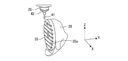
- the machine tool 11 includes a bed 13 as a base and a column 15 erected on the upper surface of the bed 13.
- a moving body 27 is arranged on the upper surface of the bed 13.
- the moving body 27 supports a rotary table 35 that rotates the work W via the tilt swivel table 28.
- the rotary table 35 has a work mounting surface 35a for fixing the work W.
- a saddle 17 is placed on the front of the column 15. Further, a spindle head 21 is arranged on the front surface of the saddle 17. A spindle 25 is attached to the spindle head 21. A rotary tool T for machining the work W is attached to the spindle 25. The rotary tool T processes the work W while rotating together with the spindle 25.
- the machine tool 11 in the present embodiment includes a moving device that changes the relative positions of the rotary tool T and the work W.
- a machine coordinate system with a predetermined position on the machine tool as the origin is set.
- the X-axis, Y-axis, and Z-axis that are orthogonal to each other in the machine coordinate system are predetermined.
- the direction in which the axis of the spindle 25 extends (vertical direction in FIG. 1) is referred to as the Z axis.
- the axis extending in the horizontal direction in which the moving body 27 moves is referred to as a Y axis.
- the axis extending in the horizontal direction in which the saddle 17 moves, that is, in the direction perpendicular to the Z axis and the Y axis is referred to as an X axis.
- the moving device can relatively move the rotary tool T and the work W in the X-axis direction, the Y-axis direction, and the Z-axis direction. Further, the moving device rotates the work W relative to the rotary tool T in the B-axis direction around the axis 52 of the inclined swivel table 28 and in the C-axis direction around the axis 53 of the rotary table 35. Can be done.
- the moving device includes an X-axis moving device that moves the rotary tool T relative to the work W in the X-axis direction.
- the X-axis moving device includes a pair of X-axis rails 19a, 19b formed on the front surface of the column 15.
- the saddle 17 is formed so as to be able to reciprocate along the X-axis rails 19a and 19b.
- the X-axis moving device moves the saddle 17 by a ball screw mechanism.
- the X-axis moving device includes an X-axis servomotor 20 that rotates the screw shaft of the ball screw mechanism.
- the X-axis moving device moves the saddle 17 by driving the X-axis servomotor 20.
- the spindle head 21 and the rotary tool T move in the X-axis direction together with the saddle 17.
- the moving device includes a Z-axis moving device that moves the rotary tool T relative to the work W in the Z-axis direction.
- the Z-axis moving device includes a pair of Z-axis rails 23a, 23b formed on the front surface of the saddle 17.
- the spindle head 21 is formed so as to be able to reciprocate along the Z-axis rails 23a and 23b.
- the Z-axis moving device moves the spindle head 21 by a ball screw mechanism.
- the Z-axis moving device includes a Z-axis servomotor 24 that rotates the screw shaft of the ball screw mechanism.
- the Z-axis moving device moves the spindle head 21 by driving the Z-axis servomotor 24.
- the rotary tool T moves in the Z-axis direction together with the spindle head 21. Further, inside the spindle head 21, a drive motor that rotates the spindle 25 around the axis is arranged.
- FIG. 3 shows a schematic perspective view of the Y-axis moving device according to the embodiment of the present embodiment.
- the moving device includes a Y-axis moving device that moves the rotary tool T relative to the work W in the Y-axis direction.
- the Y-axis moving device includes a pair of Y-axis rails 29a, 29b arranged on the upper surface of the bed 13.
- the moving body 27 is formed so as to be able to reciprocate along the Y-axis rails 29a and 29b.
- a cavity 15a is formed in the column 15 so that the moving body 27 can move in the Y-axis direction.
- the Y-axis moving device moves the moving body 27 by the ball screw mechanism 30.
- the Y-axis moving device includes a Y-axis servomotor 32 that rotates the screw shaft of the ball screw mechanism.
- the Y-axis moving device moves the moving body 27 by driving the Y-axis servomotor 32.
- the tilt swivel table 28 and the rotary table 35 move in the Y-axis direction together with the moving body 27.
- the moving device includes a B-axis rotating moving device that rotates the rotary tool T relative to the work W in the B-axis direction.
- the axis 52 of the B axis in this embodiment is not parallel to any of the X axis, the Y axis, and the Z axis. That is, the axis 52 of the B axis is inclined with respect to each of the three linear motion axes.
- the B-axis rotary moving device includes an inclined swivel table 28. Inside the moving body 27, a servomotor for rotating the inclined swivel table 28 is arranged. By driving the servomotor of the tilt swivel table 28, the tilt swivel table 28 rotates around the axis 52 of the B axis.
- the work W rotates in the B-axis direction together with the inclined swivel table 28 and the rotary table 35.
- the moving device in the present embodiment includes a C-axis rotating moving device that rotates the rotary tool T relative to the work W in the C-axis direction.
- the C-axis axis 53 is designed to be parallel to the Z-axis when the tilt swivel 28 is at a predetermined angle position in the B-axis direction.
- the C-axis rotary moving device includes a rotary table 35.
- a servomotor is arranged inside the tilting swivel table 28. By driving this servomotor, the rotary table 35 rotates around the axis 53 of the C axis.
- the work W rotates in the C-axis direction together with the rotary table 35.
- the machine tool 11 has three linear motion axes in which the spindle 25 moves relative to the work W. That is, the machine tool 11 has an X-axis, a Y-axis, and a Z-axis as linear motion axes.
- the first linear motion axis will be described as the Y axis
- the second linear motion axis will be described as the Z axis
- the third linear motion axis will be described as the X axis.
- the machine tool 11 has two rotation axes in which the spindle 25 rotates relative to the work W. That is, the machine tool 11 has a B-axis axis 52 and a C-axis axis 53 as rotation axes.
- the first rotation direction will be the C-axis direction
- the second rotation direction will be the B-axis direction
- the first axis will be referred to as the C-axis axis 53
- the second axis will be referred to as the B-axis axis 52.
- the machine tool in this embodiment includes a control device 70.
- the control device 70 is connected to a servomotor or a drive motor of the mobile device.
- the control device 70 can move the rotary tool T relative to the work W by controlling the servomotor of the moving device.
- the surface of the rotary table 35 is a plane including the X-axis and the Y-axis of the machine coordinate system, that is, the XY plane. It is preferable to manufacture the machine so that the axis 52 of the B axis and the axis 53 of the C axis intersect with each other. However, the surface of the rotary table 35 may be slightly tilted or the axis 52 and the axis 53 may be slightly separated due to manufacturing errors, aging, and the like.
- the machine tool 11 includes an angle adjusting device as an adjusting means for adjusting the inclination of the moving body 27.
- the inclination of the moving body 27 is adjusted so that the axis 52 of the B axis and the axis 53 of the C axis extend parallel to the YZ plane over the Y-axis stroke of the moving body 27.
- a state in which the B-axis axis 52 and the C-axis axis 53 extend parallel to the YZ plane while the moving body 27 is moving in the Y-axis direction is referred to as a reference state. ..
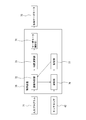
- the machine tool 11 includes a control device 70.
- the control device 70 includes a reading / interpreting unit 72, an interpolation calculation unit 73, and a servomotor control unit 74.
- the reading / interpreting unit 72 reads the input program 71 and sends the programmed movement command to the interpolation calculation unit 73.
- the interpolation calculation unit 73 calculates the position command value for each interpolation cycle, and sends the position command value to the servomotor control unit 74. For example, the interpolation calculation unit 73 calculates the movement amount for each time interval set based on the movement command.
- the servomotor control unit 74 drives each axis servomotor 75 based on the position command value.
- the control device 70 includes a calculation unit 76 connected to the measuring device 40 described later, and a storage unit 77 connected to the reading / interpretation unit 72 and the calculation unit 76.
- a predetermined surface portion of the test work 1 (FIGS. 6 to 11) is processed before the main processing of processing the work W.
- the rotary tool 2 used for machining the test work 1 is the same rotary tool as the rotary tool T used for the main machining.
- the rotary tool 2 can be a ball end mill.
- the test work 1 has a rectangular parallelepiped shape. In the present invention, the rectangular parallelepiped shape includes a cube shape.
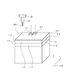
- the rotary table 35 is placed at the position shown in FIG. At this position, the work mounting surface 35a of the rotary table 35 is arranged perpendicular to the Z axis. This position of the rotary table 35 is referred to as a first position.
- the rotary table 35 is arranged at the second position shown in FIG.
- the work mounting surface 35a of the rotary table 35 is arranged perpendicular to the work mounting surface 35a of the rotary table 35 at the first position, parallel to the Z axis, which is one of the three orthogonal axes, and The other axis, in this embodiment, is in a position perpendicular to the Y axis.
- the B axis When the rotary table 35 is in the first position, the B axis is in the rotation position of 0 ° (zero degree). When the B axis is 0 ° and the C axis is in the rotation position of 0 °, the rotary table 35 is said to be in the first posture. That is, when the rotary table 35 is in the first posture, both the B axis and the C axis are in the origin position. When the rotary table 35 is fed 180 ° toward the second position as shown by the arrow 105 without rotating the C axis from the first posture, the rotary table 35 has a B axis of 180 °. The C axis moves to the rotation position of 0 °. This rotation position is set as the second posture of the rotary table 35.
- the rotation position when the C-axis is rotated by 90 ° is set as the third posture of the rotary table 35, and the rotation position when the C-axis is further rotated by 90 ° is the fourth posture of the rotary table 35.
- the posture and the rotation position when the C axis is further rotated by 90 ° are set as the fifth posture of the rotary table 35.
- the two opposing side surfaces are perpendicular to the X axis, and the other two opposite side surfaces are perpendicular to the Y axis. Is placed in.
- one side surface (upper surface) of the test work mounted on the work mounting surface 35a is perpendicular to the Z axis, which is one of the three orthogonal axes, and faces the rotary tool 2.
- the upper surface facing the rotary tool 2 has two surface portions 1-1 and 1-2 to be tested. Further, in the test work 1, each of the four side surfaces vertically connected to the upper surface having the two surface portions 1-1 and 1-2 should also be tested and processed by the rotary tool 2. It has 3, 1-7; 1-4, 1-8; 1-5, 1-9; 1-6, 1-10.
- the two surface portions 1-1 and 1-2 on the upper surface can be rectangular, preferably square, and preferably rectangular, including one ridge (edge) of the rectangular parallelepiped test work 1. Can be done.
- the two surface portions of each of the four sides connected to the top surface can have a rectangular or strip shape of constant width.
- the rotary table 35 is placed in the first posture, and one of the two surface portions on the upper surface of the test work 1 is linearly fed with the rotary table 35 in the three orthogonal axes (X-axis, Y-axis, Z-axis). At the same time, it is processed by the tip of the rotary tool 2.
- the upper surface portion 1 that is, the surface portion 1 adjacent to the upper surface of the test work 1.
- -3, 1-4, 1-5, 1-6 are machined on the side surface of the rotary tool 2 as shown in FIG.
- the machining mode by linear feed in the orthogonal three-axis (X-axis, Y-axis, Z-axis) direction is referred to as three-axis machining.
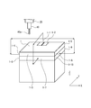
- the rotary table 35 is then rotationally fed in the B-axis direction to the second position ( It is arranged in FIG. 4). At this time, one of the side surfaces of the test work 1 is arranged perpendicular to the Z axis and faces the rotary tool 2. Next, the rotary table 35 is rotated 180 ° in the C-axis direction, and as shown in FIG. 8, the two surface portions 1-1 and 1-2 to be machined on the upper surface are arranged on the upper side, that is, closer to the rotary tool 2. do. At this time, the rotary table 35 is arranged in the fourth posture.
- the rotary table 35 With the rotary table 35 arranged at this position in the fourth posture, the rotary table 35 is linearly fed in the three orthogonal axes (X-axis, Y-axis, Z-axis) to perform test processing on the upper surface of the test work 1.
- the other 1-2 of the surface portion is machined on the side surface of the rotary tool 2.
- the processing parameters of the surface portion 1-1 and the surface portion 1-2 are set so as to be a processed surface having no step in the processing program.
- the other surface portion 1-7 of the two surface portions to be machined on each of the four side surfaces connected perpendicularly to the upper surface of the test work 1 is formed by the tip of the rotary tool 2. Process.
- the C-axis is rotated by 90 °, the rotary table 35 is arranged in the fifth posture, and the surface portion 1-8 is machined with the tip of the rotary tool 2, and the surface portion is processed.
- the C-axis is further rotated by 90 °, the rotary table 35 is placed in the second posture, and the surface portion 1-9 is machined with the tip of the rotary tool 2.
- the surface portion When the machining of 1-9 is completed, the C-axis is further rotated by 90 °, the rotary table 35 is arranged in the third posture, and the surface portion 1-10 is machined with the tip of the rotary tool 2.
- the machining mode by linear feed in the orthogonal three axes (X-axis, Y-axis, Z-axis) direction and rotary feed by two rotary feed axes (B-axis, C-axis) is referred to as 5-axis machining.
- Surface part 1-3 and surface part 1-7, surface part 1-4 and surface part 1-8, surface part 1-5 and surface part 1-9, surface part 1-6 and surface part 1-10 are processed.
- machining parameters are set so that the machined surface has no steps.
- the rotary table 35 is placed in the first posture.
- the upper surface of the test work 1 is arranged perpendicular to the Z axis, and two of the four side surfaces connected perpendicularly to the upper surface.
- the surface portions 1-3, 1-7 and the surface portion 1 The side surfaces with -5 and 1-9 are arranged perpendicular to the Y axis, and the side surfaces with surface portions 1-4 and 1-8 and surface portions 1-6 and 1-10 are arranged perpendicular to the X axis.
- NS the rotary tool 2 is removed from the spindle 25, and the measuring device 40 is attached to the spindle 25 instead.
- the measuring device 40 can be a touch sensor that outputs a signal when the measuring probe 40a comes into contact with the surface of the object to be measured.
- the measuring probe 40a of the measuring device 40 is placed above each of the two surface portions 1-1 and 1-2 on the upper surface of the test work 1, and is used for testing along the Z axis.
- the Z coordinates Z 1-1 and Z 1-2 of the two surface portions 1-1 and 1-2 are measured. That is, the measuring device 40 sends a signal in which the measuring probe 40a comes into contact with each of the surface portions 1-1 and 1-2 to the calculation unit 76, and the calculation unit 76 causes the measurement probe 40a to send the measurement bulb 44 surface portion 1-.
- the Z coordinate at the time of contact with each of 1, 1-2 is detected and stored in the storage unit 77.
- the surface portions 1-3, 1-4, 1-5, 1-6 of each of the four side surfaces connected to the upper surface of the test work 1 and the surface portions 1-7 The measuring probe 40a of the measuring device 40 is brought into contact with each of the surface portions by linearly feeding in a direction perpendicular to 1-8, 1-9, and 1-10.
- the calculation unit 76 detects the coordinate value at that time and stores it in the storage unit 77. More specifically, the Y coordinates Y 1-3 and Y 1-5 of the surface portions 1-3 and 1-5 and the Y coordinates Y 1-7 and Y 1-9 of the surface portions 1-7 and 1-9. , X coordinates X 1-4 , X 1-6 of surface parts 1-4, 1-6 and X coordinates X 1-8 , X 1-10 of surface parts 1-8, 1-10 are measured and stored. It is stored in the part 77.
- the coordinates (X C5 , Y C5 ) ((X 1-8 + X 1-10 ) / 2, (Y 1-7 + Y 1-9 ) / 2) of the center C5 of 6.
- the calculation result is stored in the storage unit 77.
- and the distance between surface parts 1-3, 1-5 ⁇ 3
- the difference ⁇ ⁇ 3- ⁇ 5 between the distance ⁇ 3 between the surface portions in the direction and the distance ⁇ 5 between the surface portions in the X direction by 5-axis processing is calculated, and the calculation result is stored in the storage unit 77.
- the calculation unit 76 determines the correction amount CV as follows.
- CV4 ⁇ + CV3
- CV5 (( ⁇ + CV3)) + ( ⁇ + CV4)) / 2
- CV1 is the X-direction correction amount of the rotation center of the rotary table 35
- CV2 is the Y-direction correction amount of the rotation center of the rotary table 35
- CV3 is the Z-axis correction amount
- CV4 is the tool length direction of the rotary tool 2.
- the correction amount of the tool measuring device, CV5, is the correction amount of the Z coordinate in the work coordinate system (calibration value in the Z direction of the measuring device 40).
- the measurement of the test work 1 described above can be automatically performed by inputting an automatic measurement program as an input program 71 to the control device 70.
- an automatic measurement program as an input program 71 to the control device 70.
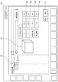
- the control device 70 executes the automatic measurement program, for example, the input screen shown in FIG. 13 is displayed on a display device such as a touch panel attached to a control panel (not shown) of the machine tool 11.
- the input screen 100 is the area 102, 104, 106 for inputting machining parameters such as dimensions in the X, Y, and Z directions and the depth of cut (depth from the surface of the test work 1) as the size of the test work 1. , 108.
- One of the areas 102, 104, 106, and 108 is activated, and a numerical value is input to each of the areas 102, 104, 106, and 108 using an input device (not shown) such as a keyboard.
- the input processing parameters of the test work 1 are stored in the storage unit 77.
- the input screen 100 can include an area 120 for displaying the machining process of the test work 1 such as the work origin check, the type of the tool to be used, and the like. Further, the approximate shape 130 of the test work 1 may be displayed.
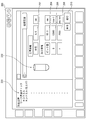
- the tool information input screen 200 shown in FIG. 14 can be displayed.
- the tool information input screen 200 includes areas for inputting tool parameters such as tool diameter, and areas 202, 204, 206, and 208 for inputting pick feed amount, spindle rotation speed, and feed speed as machining conditions.
- the input tool parameters and machining conditions are stored in the storage unit 77.
- the input screen 100 can include an area 220 for displaying the machining process of the test work 1 such as the work origin check, the type of tool to be used, and the like. Further, the approximate shape 230 of the tool used for machining the test work 1 may be displayed.
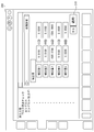
- the test work 1 described above is processed and measured, and the calculation result of the correction amount can be displayed on the correction amount display screen 300 shown in FIG.
- the operator confirms the correction amount and taps the apply button 310 to perform the processing to which the correction amount is applied in the main processing.
Abstract
L'invention concerne un procédé d'usinage pour effectuer un usinage par déplacement relatif d'un outil rotatif (T) équipé d'un arbre principal (25) et d'une pièce (W) fixée à une table rotative (35) dans un outil d'usinage (11) ayant un arbre d'alimentation linéaire et un arbre d'alimentation rotatif, une pièce de test (1) est fixée sur la table rotative, les positions de la pièce de test sont déterminées avec une pluralité d'orientations, une partie prescrite de la surface de la pièce de test est usinée par l'outil rotatif (2) utilisé lors de l'usinage principal, chaque partie de surface usinée de la pièce de test est mesurée, et, sur la base des résultats de mesure, une erreur dans l'arbre d'alimentation rotatif est corrigée avec des informations de position concernant le centre rotatif de la table rotative par rapport à des coordonnées de machine et une quantité de correction d'une longueur d'outil de l'outil rotatif.
Priority Applications (2)
| Application Number | Priority Date | Filing Date | Title |
|---|---|---|---|
| CN202180024793.9A CN115516389A (zh) | 2020-04-10 | 2021-04-09 | 加工方法 |
| EP21784255.8A EP4134762A4 (fr) | 2020-04-10 | 2021-04-09 | Procédé d'usinage |
Applications Claiming Priority (2)
| Application Number | Priority Date | Filing Date | Title |
|---|---|---|---|
| JP2020-071116 | 2020-04-10 | ||
| JP2020071116A JP7026718B2 (ja) | 2020-04-10 | 2020-04-10 | 加工方法 |
Publications (1)
| Publication Number | Publication Date |
|---|---|
| WO2021206172A1 true WO2021206172A1 (fr) | 2021-10-14 |
Family
ID=78022519
Family Applications (1)
| Application Number | Title | Priority Date | Filing Date |
|---|---|---|---|
| PCT/JP2021/015080 WO2021206172A1 (fr) | 2020-04-10 | 2021-04-09 | Procédé d'usinage |
Country Status (4)
| Country | Link |
|---|---|
| EP (1) | EP4134762A4 (fr) |
| JP (1) | JP7026718B2 (fr) |
| CN (1) | CN115516389A (fr) |
| WO (1) | WO2021206172A1 (fr) |
Cited By (1)
| Publication number | Priority date | Publication date | Assignee | Title |
|---|---|---|---|---|
| CN116000652A (zh) * | 2023-03-22 | 2023-04-25 | 北京博鲁斯潘精密机床有限公司 | 一种航空发动机叶片高刚度高精度五轴联动加工数控机床 |
Citations (6)
| Publication number | Priority date | Publication date | Assignee | Title |
|---|---|---|---|---|
| JP2005061834A (ja) | 2003-08-08 | 2005-03-10 | Toyoda Mach Works Ltd | 回転軸を有する加工機の誤差算出方法 |
| WO2009057229A1 (fr) * | 2007-11-02 | 2009-05-07 | Makino Milling Machine Co., Ltd. | Procédé et dispositif pour préparer une carte d'erreurs et machine-outil à commande numérique possédant une fonction de préparation de carte d'erreurs |
| WO2012101742A1 (fr) * | 2011-01-24 | 2012-08-02 | 三菱電機株式会社 | Dispositif et procédé de mesure d'erreur |
| WO2017130412A1 (fr) * | 2016-01-29 | 2017-08-03 | 株式会社ニコン | Procédé de correction d'appareil d'usinage et appareil d'usinage |
| KR20190002099A (ko) * | 2017-06-29 | 2019-01-08 | 현대위아 주식회사 | 5축 가공장치의 피봇 교정 방법 |
| JP2019040586A (ja) * | 2017-08-28 | 2019-03-14 | ファナック株式会社 | 評価用ワーク、加工プログラム及びデータ構造 |
-
2020
- 2020-04-10 JP JP2020071116A patent/JP7026718B2/ja active Active
-
2021
- 2021-04-09 EP EP21784255.8A patent/EP4134762A4/fr active Pending
- 2021-04-09 CN CN202180024793.9A patent/CN115516389A/zh active Pending
- 2021-04-09 WO PCT/JP2021/015080 patent/WO2021206172A1/fr unknown
Patent Citations (6)
| Publication number | Priority date | Publication date | Assignee | Title |
|---|---|---|---|---|
| JP2005061834A (ja) | 2003-08-08 | 2005-03-10 | Toyoda Mach Works Ltd | 回転軸を有する加工機の誤差算出方法 |
| WO2009057229A1 (fr) * | 2007-11-02 | 2009-05-07 | Makino Milling Machine Co., Ltd. | Procédé et dispositif pour préparer une carte d'erreurs et machine-outil à commande numérique possédant une fonction de préparation de carte d'erreurs |
| WO2012101742A1 (fr) * | 2011-01-24 | 2012-08-02 | 三菱電機株式会社 | Dispositif et procédé de mesure d'erreur |
| WO2017130412A1 (fr) * | 2016-01-29 | 2017-08-03 | 株式会社ニコン | Procédé de correction d'appareil d'usinage et appareil d'usinage |
| KR20190002099A (ko) * | 2017-06-29 | 2019-01-08 | 현대위아 주식회사 | 5축 가공장치의 피봇 교정 방법 |
| JP2019040586A (ja) * | 2017-08-28 | 2019-03-14 | ファナック株式会社 | 評価用ワーク、加工プログラム及びデータ構造 |
Non-Patent Citations (1)
| Title |
|---|
| See also references of EP4134762A4 |
Cited By (1)
| Publication number | Priority date | Publication date | Assignee | Title |
|---|---|---|---|---|
| CN116000652A (zh) * | 2023-03-22 | 2023-04-25 | 北京博鲁斯潘精密机床有限公司 | 一种航空发动机叶片高刚度高精度五轴联动加工数控机床 |
Also Published As
| Publication number | Publication date |
|---|---|
| CN115516389A (zh) | 2022-12-23 |
| JP7026718B2 (ja) | 2022-02-28 |
| EP4134762A4 (fr) | 2024-04-17 |
| EP4134762A1 (fr) | 2023-02-15 |
| JP2021168043A (ja) | 2021-10-21 |
Similar Documents
| Publication | Publication Date | Title |
|---|---|---|
| JP5705283B2 (ja) | 工作機械および工作機械の回転軸の測定方法 | |
| US10209107B2 (en) | Geometric error identification method of multi-axis machine tool and multi-axis machine tool | |
| US10118227B2 (en) | Machine tool and workpiece flattening method | |
| KR101158772B1 (ko) | 수치제어 공작기계 및 수치제어 장치 | |
| JP2007044802A (ja) | 多軸工作機械における旋回軸中心測定方法 | |
| JP5911565B2 (ja) | 工作機械の干渉判定方法および干渉判定装置 | |
| JP4276270B2 (ja) | 接触検知によるワークの基準位置設定機能を有する工作機械 | |
| JP6955296B2 (ja) | 切削装置および接触位置特定プログラム | |
| JP2009012083A (ja) | 工作機械の運動誤差測定方法及び運動誤差測定装置 | |
| JP2014215079A (ja) | 幾何偏差測定方法、及び、幾何偏差計測装置 | |
| JP2010105117A (ja) | 精度測定方法及び数値制御工作機械の誤差補正方法並びに誤差補正機能を有した数値制御工作機械 | |
| WO2021206172A1 (fr) | Procédé d'usinage | |
| JP2831610B2 (ja) | 測定装置 | |
| US11543230B2 (en) | Articulating probe | |
| JP2018128328A (ja) | 工作機械の幾何誤差測定方法 | |
| US20230152772A1 (en) | Positional relationship measurement method and machining apparatus | |
| JP6425009B2 (ja) | 三次元測定機、及びこれを用いた形状測定方法 | |
| JP2012079358A (ja) | エラーマップ作成方法及び装置並びにエラーマップ作成機能を有した数値制御工作機械 | |
| JP2002001568A (ja) | Nc制御3次元レーザ加工機におけるレーザ加工ヘッドのパラメータ設定方法およびnc制御3次元レーザ加工機 | |
| JP2015133073A (ja) | 工作機械の制御方法 | |
| JP7266511B2 (ja) | 工作機械における対象物の位置計測方法及び位置計測システム、位置計測プログラム | |
| JPH09204213A (ja) | レーザ加工方法及びレーザ加工機 | |
| JP7128333B1 (ja) | 多軸加工機および多軸加工機の回転中心測定方法 | |
| JP5740201B2 (ja) | 幾何誤差同定装置 | |
| JPH05277894A (ja) | 工作機械の主軸熱変位補正方法および装置 |
Legal Events
| Date | Code | Title | Description |
|---|---|---|---|
| 121 | Ep: the epo has been informed by wipo that ep was designated in this application |
Ref document number: 21784255 Country of ref document: EP Kind code of ref document: A1 |
|
| ENP | Entry into the national phase |
Ref document number: 2021784255 Country of ref document: EP Effective date: 20221110 |
|
| NENP | Non-entry into the national phase |
Ref country code: DE |