WO2021205505A1 - 熱交換換気装置及び空気調和システム - Google Patents
熱交換換気装置及び空気調和システム Download PDFInfo
- Publication number
- WO2021205505A1 WO2021205505A1 PCT/JP2020/015501 JP2020015501W WO2021205505A1 WO 2021205505 A1 WO2021205505 A1 WO 2021205505A1 JP 2020015501 W JP2020015501 W JP 2020015501W WO 2021205505 A1 WO2021205505 A1 WO 2021205505A1
- Authority
- WO
- WIPO (PCT)
- Prior art keywords
- exhaust
- air
- humidity
- air supply
- blower
- Prior art date
- Legal status (The legal status is an assumption and is not a legal conclusion. Google has not performed a legal analysis and makes no representation as to the accuracy of the status listed.)
- Ceased
Links
Images








Classifications
-
- F—MECHANICAL ENGINEERING; LIGHTING; HEATING; WEAPONS; BLASTING
- F24—HEATING; RANGES; VENTILATING
- F24F—AIR-CONDITIONING; AIR-HUMIDIFICATION; VENTILATION; USE OF AIR CURRENTS FOR SCREENING
- F24F7/00—Ventilation
- F24F7/007—Ventilation with forced flow
-
- F—MECHANICAL ENGINEERING; LIGHTING; HEATING; WEAPONS; BLASTING
- F24—HEATING; RANGES; VENTILATING
- F24F—AIR-CONDITIONING; AIR-HUMIDIFICATION; VENTILATION; USE OF AIR CURRENTS FOR SCREENING
- F24F7/00—Ventilation
- F24F7/04—Ventilation with ducting systems, e.g. by double walls; with natural circulation
- F24F7/06—Ventilation with ducting systems, e.g. by double walls; with natural circulation with forced air circulation, e.g. by fan positioning of a ventilator in or against a conduit
- F24F7/08—Ventilation with ducting systems, e.g. by double walls; with natural circulation with forced air circulation, e.g. by fan positioning of a ventilator in or against a conduit with separate ducts for supplied and exhausted air with provisions for reversal of the input and output systems
Definitions
- This disclosure relates to a heat exchange ventilation system and an air conditioning system.
- the heat exchange ventilation device described in Patent Document 1 includes a casing provided with an air supply air passage and an exhaust air passage, an air supply blower provided in the air supply air passage to form an air supply airflow from the outside to the inside, and an exhaust air.
- An exhaust blower that is installed in the road to form an exhaust flow from the room to the outside, a heat exchanger that exchanges heat between the air supply and the exhaust flow, and a heat exchanger that is installed in the air supply air passage to detect the humidity of the outside air. It is equipped with a humidity sensor.
- the air supply blower is intermittently operated to remove the high humidity outside air. It is designed not to be taken into the casing unnecessarily.
- the pressure inside the room will be negative, so even if the air supply blower and exhaust blower of the heat exchange ventilator are stopped. , High humidity outside air invades the air supply air passage and the exhaust air passage. At this time, water may condense in the heat exchanger and drain water may be generated in the heat exchanger.
- the present disclosure has been made to solve the above-mentioned problems, and suppresses the generation of drain water in the heat exchanger due to the high humidity outside air while the operation of the air supply blower and the exhaust blower is stopped. It is an object of the present invention to provide a heat exchange ventilator and an air conditioning system capable of providing a heat exchange ventilator and an air conditioning system.
- the heat exchange ventilation device is provided in the air supply air passages communicating with the indoor and outdoor air passages, the exhaust air passages communicating with the indoor and outdoor air passages, and the air supply air passages, and forms a supply air flow from the outdoor side to the indoor air supply.
- the exhaust blower of the exhaust blower It is provided with a control device for starting operation.
- the air conditioning system is for air supply that is provided in an air supply air passage that communicates with indoors and outdoors, an exhaust air passage that communicates with indoors and outdoors, and an air supply air passage that forms an air supply air flow from the outdoor to the indoors.
- a blower an exhaust blower provided in the exhaust air passage to form an exhaust flow from the room to the outside, a total heat exchanger that exchanges total heat between the supply air flow and the exhaust flow, and the humidity of the air in the exhaust air passage. Detected by the exhaust humidity detecting means while the operation of the heat exchange ventilation device equipped with the exhaust humidity detecting means for detecting the above, the air conditioning device for sending the conditioned air into the room, and the air supply blower and the exhaust blower is stopped.
- a control device for starting the operation of the exhaust blower and the dehumidifying operation of the air conditioner when the humidity becomes equal to or higher than the threshold value is provided.
- the heat exchange ventilator and the air conditioning system when the humidity detected by the exhaust humidity detecting means exceeds the threshold value while the operation of the air supply blower and the exhaust blower is stopped, it is used for exhaust. Start the operation of the blower. Therefore, when high-humidity outside air invades the supply air passage and the exhaust air passage, the relatively dry air in the room can be sent to the total heat exchanger. It is possible to suppress the generation of drain water.
- FIG. 1 It is a schematic diagram which shows the structure of the heat exchange ventilation apparatus which concerns on Embodiment 1, and is the figure which shows the state at the time of the heat exchange ventilation operation. It is a schematic diagram which shows the structure of the heat exchange ventilation apparatus which concerns on Embodiment 1, and is the figure which shows the state at the time of a normal ventilation operation. It is a perspective view which shows a part of the structure of the total heat exchanger which concerns on Embodiment 1.
- FIG. It is a control block diagram of the heat exchange ventilation apparatus which concerns on Embodiment 1.
- FIG. It is a figure which shows an example of the hardware composition of the processing circuit which concerns on Embodiment 1.
- FIG. 1 It is a schematic diagram which shows the structure of the heat exchange ventilation apparatus which concerns on Embodiment 1, and is the figure which shows the state which the outdoor air has invaded both an air supply air passage and an exhaust air passage. It is a flowchart which shows the operation of the control device of the heat exchange ventilation apparatus which concerns on Embodiment 1.
- FIG. 2 It is a flowchart which shows the operation of the control device of the heat exchange ventilation apparatus which concerns on Embodiment 2.
- FIG. It is a schematic diagram which shows the structure of the heat exchange ventilation apparatus which concerns on Embodiment 3, and is the figure which shows the state at the time of the heat exchange ventilation operation.
- It is a flowchart which shows the operation of the control device of the heat exchange ventilation apparatus which concerns on Embodiment 3.
- FIG. It is a figure which shows the structure of the air-conditioning system provided with the heat exchange ventilation system which concerns on Embodiment 4.
- FIG. It is a flowchart which shows the operation of the control device which concerns on Embodiment 4.
- FIG. It is a schematic diagram which shows the structure of the heat exchange ventilation apparatus which concerns on the modification of Embodiment 4, and is the figure which shows the state at the time of the heat exchange ventilation operation.
- FIG. 1 is a schematic view showing the configuration of the heat exchange ventilation device 100 according to the first embodiment, and is a diagram showing a state during the heat exchange ventilation operation.
- FIG. 2 is a schematic view showing the configuration of the heat exchange ventilation device 100 according to the first embodiment, and is a diagram showing a state during normal ventilation operation.
- shaded arrows indicate airflow and white arrows without diagonals indicate exhaust flow.
- the heat exchange ventilation device 100 is installed in the ceiling of a building, for example, and exchanges indoor air and outdoor air. That is, the heat exchange ventilation device 100 supplies the outdoor air OA (Outdoor Air) into the room as the supply air SA (Supply Air), and discharges the indoor air RA (Return Air) to the outside as the exhaust air EA (Exhaust Air). do.
- SA Supply Air
- EA exhaust Air
- the heat exchange ventilator 100 includes a box-shaped casing 1, an air supply blower 2, an exhaust blower 3, a total heat exchanger 4, a first air supply / humidity sensor 5, a first exhaust humidity sensor 6, and air passage switching. It includes a damper 7, a control device 8, and a remote controller 9.
- the casing 1 is provided with an air supply suction port 10 and an exhaust air outlet 11 on one side surface.
- the air supply inlet 10 and the exhaust outlet 11 are connected to the outdoor space via a duct (not shown).
- a supply air outlet 12 and an exhaust suction port 13 are provided on the side surface of the casing 1 facing the one side surface.
- the air supply outlet 12 and the exhaust suction port 13 are connected to the indoor space via a duct (not shown).
- an air supply air passage 14 connecting the air supply air suction port 10 and the air supply air outlet 12 and an exhaust air passage 15 connecting the exhaust air suction port 13 and the exhaust air outlet 11 are formed. .. That is, the air supply air passage 14 communicates with the indoor and outdoor areas through a duct (not shown). Further, the exhaust air passage 15 also communicates with the indoor and outdoor areas through a duct (not shown).
- the air supply blower 2 is provided in the air supply air passage 14 on the indoor side of the total heat exchanger 4, that is, between the total heat exchanger 4 and the air supply outlet 12.
- the air supply blower 2 forms an airflow from the outside to the room, that is, an airflow from the air supply inlet 10 to the air supply outlet 12.
- the exhaust blower 3 is provided outside the total heat exchanger 4 in the exhaust air passage 15, that is, between the total heat exchanger 4 and the exhaust outlet 11.
- the exhaust blower 3 forms an exhaust flow from the room to the outside, that is, an exhaust flow from the exhaust suction port 13 to the exhaust outlet 11.
- the total heat exchanger 4 exchanges total heat between the air supply airflow formed by the air supply blower 2 and the exhaust flow formed by the exhaust blower 3.
- the first air supply / humidity sensor 5 is an example of the air supply / humidity detecting means for detecting the humidity of the air in the air supply air passage 14.
- the first air supply / humidity sensor 5 is provided outside the total heat exchanger 4 in the air supply air passage 14, that is, between the total heat exchanger 4 and the air supply suction port 10.
- the first air supply / humidity sensor 5 detects the humidity RH OA of the air outside the room rather than the total heat exchanger 4 in the air supply air passage 14.
- the first exhaust humidity sensor 6 is an example of an exhaust humidity detecting means for detecting the humidity of the air in the exhaust air passage 15.
- the first exhaust humidity sensor 6 is provided outside the total heat exchanger 4 in the exhaust air passage 15, that is, between the total heat exchanger 4 and the exhaust outlet 11.
- the first exhaust humidity sensor 6 detects the humidity RH EA of the air outside the room rather than the total heat exchanger 4 in the exhaust air passage 15.
- the air passage switching damper 7 switches between a heat exchange ventilation operation in which total heat is exchanged between the air supply and the exhaust flow and a normal ventilation operation in which total heat is not exchanged between the air supply and the exhaust flow. It is a switching means. Specifically, in the air passage switching damper 7, at least one of the air flow and the exhaust flow is the total heat exchanger 4 and the air passage during the heat exchange ventilation operation in which the air supply and the exhaust flow pass through the total heat exchanger 4. Switch between the air passage during normal ventilation operation and the air passage that bypasses. In the present embodiment, the exhaust flow bypasses the total heat exchanger 4 during the normal ventilation operation.
- the air passage switching damper 7 is provided in the exhaust air passage 15 on the indoor side of the total heat exchanger 4, that is, between the total heat exchanger 4 and the exhaust suction port 13.
- the exhaust air passage 15 is provided with a bypass air passage 16 in which the exhaust flow bypasses the total heat exchanger 4, and the air passage switching damper 7 opens and closes the bypass air passage 16.
- the air passage switching damper 7 closes the bypass air passage 16, so that the exhaust flow passes through the total heat exchanger 4. Further, during the normal ventilation operation, as shown in FIG. 2, the air passage switching damper 7 opens the bypass air passage 16, so that the exhaust flow bypasses the total heat exchanger 4 and passes through the bypass air passage 16.
- the exhaust flow bypasses the total heat exchanger 4 during the normal ventilation operation, but the air supply may bypass the total heat exchanger 4. Further, during the normal ventilation operation, both the supply air flow and the exhaust flow may bypass the total heat exchanger 4.
- the remote controller 9 is a user interface, and is an input operation such as switching between operation and stop of the heat exchange ventilation device 100, switching between heat exchange ventilation operation and normal ventilation operation, and changing the air volume of the air supply blower 2 and the exhaust blower 3. Is possible.
- FIG. 3 is a perspective view showing a part of the configuration of the total heat exchanger 4 according to the first embodiment.
- the shaded arrows indicate the air supply and the white arrows without the diagonal lines indicate the exhaust flow.
- the total heat exchanger 4 has a laminated structure in which a sheet-shaped partition member 41 and a wavy bent interval holding member 42 are alternately laminated.
- the supply air passage 14 or the exhaust air passage 15 is formed by the two partition members 41 and the one spacing member 42. Further, the spacing member 42 is laminated so that the folds of the two spacing member 42 sandwiching the partition member 41 are orthogonal to each other.
- the air supply air passages 14 and the exhaust air passages 15 are alternately formed in the stacking direction so that the air supply airflow passing through the air supply air passage 14 and the exhaust flow passing through the exhaust air passage 15 are orthogonal to each other.
- FIG. 4 is a control block diagram of the heat exchange ventilation device 100 according to the first embodiment.
- the control device 8 has information on the humidity RH OA detected by the first supply air humidity sensor 5, information on the humidity RH EA detected by the first exhaust humidity sensor 6, and a remote control.
- the operation information input in 9 is input.
- the control device 8 controls the operations of the air supply blower 2, the exhaust blower 3, and the air passage switching damper 7 based on the input information.
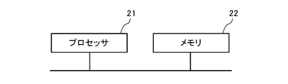
- the control device 8 is realized, for example, as a processing circuit having a hardware configuration shown in FIG.
- FIG. 5 is a diagram showing an example of the hardware configuration of the processing circuit according to the first embodiment.
- the control device 8 includes, for example, a processor 21 which is a calculation unit and a memory 22 which is a storage unit. When the processor 21 executes the program stored in the memory 22, each function of the control device 8 is realized. It should be noted that a plurality of processors and a plurality of memories may be linked to realize each function of the control device 8.
- the control device 8 operates the air passage switching damper 7 so as to close the bypass air passage 16, and also operates the air supply blower 2 and the exhaust blower 3.
- the outdoor air OA that has undergone total heat exchange with the indoor air RA is supplied to the room as the supply air SA.
- the control device 8 operates the air passage switching damper 7 so as to open the bypass air passage 16, and also operates the air supply blower 2 and the exhaust blower 3. ..
- the outdoor air OA that has not undergone total heat exchange with the indoor air RA is supplied to the room as the supply air SA as it is.
- the heat exchange ventilation operation and the normal ventilation operation can be switched manually by the remote controller 9. Further, the switching between the heat exchange ventilation operation and the normal ventilation operation may be automatically performed by the control device 8 by comparing the indoor temperature with the outdoor temperature.
- the air supply blower 2 and the exhaust blower 3 can be operated with a multi-stage air volume.
- the air volume of the air supply blower 2 and the exhaust blower 3 can be manually changed by the remote controller 9. Further, the air volumes of the air supply blower 2 and the exhaust blower 3 may be automatically changed according to the control contents stored in the control device 8.
- first air supply humidity sensor 5 and the first exhaust humidity sensor 6 constantly detect the humidity regardless of the operating state of the air supply blower 2 and the exhaust air blower 3. Humidity information detected by the first supply air humidity sensor 5 and the first exhaust humidity sensor 6 is periodically transmitted to the control device 8.
- FIG. 6 is a schematic view showing the configuration of the heat exchange ventilation device 100 according to the first embodiment, and is a diagram showing a state in which outdoor air has invaded both the supply air passage 14 and the exhaust air passage 15.
- the shaded arrows indicate the flow of outdoor air.
- the air passage switching damper 7 closes the bypass air passage 16 so that insects and dust do not easily enter the room.
- the outdoor air that has entered the air supply air passage 14 and the exhaust air passage 15 passes through the air supply air passage 14 and the exhaust air passage 15 inside the total heat exchanger 4, so that the total heat exchanger 4 is the air supply air passage. Both the 14 and the exhaust air passage 15 will be exposed to the outdoor air.
- the air passage switching damper 7 may open the bypass air passage 16 while the heat exchange ventilation device 100 is stopped in the ventilation operation. Even in this case, the total heat exchanger 4 is exposed to the outdoor air in both the air supply air passage 14 and the exhaust air passage 15 by the outdoor air entering the air supply air passage 14 and the exhaust air passage 15. become.
- the heat exchange ventilator 100 is equipped with a drain pan that receives the drain water dropped from the total heat exchanger 4, if drain water exceeding the capacity of the drain pan is generated, the drain water overflows from the drain pan and heat exchange is performed. Drain water may leak to the outside of the ventilation device 100. Further, since increasing the capacity of the drain pan leads to an increase in the size of the heat exchange ventilation device 100, it is preferable to suppress the generation of drain water in order to reduce the capacity of the drain pan.
- the total heat exchanger 4 is exposed to high humidity outdoor air in both the air supply air passage 14 and the exhaust air passage 15. Under the conditions assumed to be, the operation of the exhaust blower 3 is started. As a result, relatively dry indoor air can be sent to the total heat exchanger 4 to dry the total heat exchanger 4, so that it is possible to suppress the generation of drain water in the total heat exchanger 4.
- the humidity RH EA detected by the first exhaust humidity sensor 6 is equal to or higher than the first threshold value RHa, for example, 90% or higher, all of the air passages 14 and 15 are exhausted. It is determined that the heat exchanger 4 is exposed to high humidity outdoor air.
- the exhaust flow that is, the indoor air, which normally flows through the exhaust air passage 15 during the operation of the exhaust blower 3, remains in the exhaust air passage 15. doing.
- the Building Sanitation Law stipulates that the humidity in the room where the air conditioning equipment is installed should be maintained at 40% or more and 70% or less. Therefore, when the humidity of the air in the exhaust air passage 15 is, for example, 90% or more, it is considered that the air existing in the exhaust air passage 15 is not indoor air but outdoor air. Further, when the outdoor air enters the exhaust air passage 15 through the duct connected to the exhaust outlet 11, it is considered that the indoor pressure is negative, so that the air supply air passage 14 is also outdoors. It is considered that air is invading.
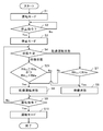
- FIG. 7 is a flowchart showing the operation of the control device 8 of the heat exchange ventilation device 100 according to the first embodiment.
- step S1 the control device 8 starts the operation mode and starts the operation of the air supply blower 2 and the exhaust blower 3.
- the air passage switching damper 7 controls to close the bypass air passage 16, and receives the normal ventilation operation start command. In this case, the air passage switching damper 7 controls to open the bypass air passage 16.
- the control device 8 started the operation mode by receiving an operation command from the remote controller 9, but the start of the operation mode is not limited to that by the remote controller 9.
- the operation mode may be automatically started at a time set in advance by the remote controller 9.
- step S2 determines in step S2 whether or not a stop command has been received from the remote controller 9. In step S2, if it is determined that the control device 8 has received the stop command from the remote controller 9, the process proceeds to step S3, and if it is determined that the stop command has not been received from the remote controller 9, the process returns to step S2.
- step S3 the control device 8 changes from the operation mode to the stop mode, and stops the operation of the air supply blower 2 and the exhaust blower 3.
- step S2 when the control device 8 determines that the stop command has been received from the remote controller 9, the control device 8 proceeds to step S3 and changes to the stop mode, but the change to the stop mode is not limited to that by the remote controller 9.
- the control device 8 when the control device 8 is provided with a timer, it may be automatically changed to the stop mode when the time set in advance by the remote controller 9 is reached.
- step S4 the control device 8 determines the state in the stop mode.
- the state in the stop mode includes a standby state and a dry operation state.
- the standby state is a state in which the air supply blower 2 and the exhaust blower 3 have stopped operating in the stop mode.
- the dry operation state is a state in which the exhaust blower 3 is operated in the stop mode.
- step S3 Immediately after the mode is changed to the stop mode in step S3, the air supply blower 2 and the exhaust blower 3 are in a standby state in which the operation is stopped. Therefore, the control device 8 determines in step S4 that it is in the standby state, and proceeds to step S5.
- step S5 the control device 8 determines whether or not the humidity RH EA detected by the first exhaust gas humidity sensor 6 is equal to or higher than the first threshold value RHa.
- the first threshold value RHa is preferably set to 90%, which is the outdoor humidity reached under high humidity conditions such as low temperature in the morning and evening and high humidity conditions such as rain.
- the first threshold value RHa does not have to be 90%, and may be set to a humidity at which drain water is expected to be generated in the total heat exchanger 4.
- the first threshold value RHa is preset in the control device 8.
- step S5 when the control device 8 determines that the humidity RH EA detected by the first exhaust gas humidity sensor 6 is equal to or higher than the first threshold value RHa, the control device 8 proceeds to step S6.
- step S6 the control device 8 changes the state in the stop mode from the standby state to the dry operation state, and starts the operation of the exhaust blower 3.
- the control device 8 operates the air passage switching damper 7 so as to be the air passage during the heat exchange ventilation operation. That is, when the air passage switching damper 7 closes the bypass air passage 16, the bypass air passage 16 is kept closed, and when the air passage switching damper 7 opens the bypass air passage 16, the bypass air passage 16 is opened. Close.
- relatively dry air in the room can be sent to the total heat exchanger 4, and the total heat exchanger 4 can be dried.
- step S6 only the exhaust blower 3 needs to be operated in order to send the indoor air to the total heat exchanger 4, and the air supply blower 2 does not need to be operated. However, if only the exhaust blower 3 is operated, there is a possibility that problems such as excessive exhaust, negative pressure in the room, difficulty in opening and closing the door, and noise may occur. Therefore, in step S6, although the drying effect of the total heat exchanger 4 is diminished, not only the exhaust blower 3 but also the air supply blower 2 may be operated.
- the air volume of the air supply blower 2 when operating the air supply blower 2, if the air volume of the air supply blower 2 is operated in a state where the air volume of the air supply blower 2 is lower than the air volume of the exhaust blower 3, the decrease in the drying effect of the total heat exchanger 4 is suppressed. At the same time, the problem caused by the negative pressure in the room can be alleviated.
- step S5 when the control device 8 determines that the humidity RH EA detected by the first exhaust humidity sensor 6 is smaller than the first threshold value RHa, the control device 8 proceeds to step S8.
- step S8 the control device 8 maintains a standby state in which the air supply blower 2 and the exhaust blower 3 have stopped operating.
- step S9 the control device 8 determines whether or not an operation command has been received from the remote controller 9. If it is determined in step S9 that the control device 8 has not received the operation command, the process returns to step S4.
- step S4 the control device 8 determines that the state in the stop mode is the dry operation state, and proceeds to step S7.
- step S7 the control device 8 determines whether or not the humidity RH OA detected by the first air supply humidity sensor 5 is smaller than the first threshold value RHa.
- the humidity RH OA detected by the first air supply / humidity sensor 5 corresponds to the humidity of the outdoor air.
- the outdoor air is smaller than the first threshold value RHa, it is unlikely that drain water will be generated in the total heat exchanger 4 even if the outdoor air invades both the supply air passage 14 and the exhaust air passage 15. ..
- step S7 when the control device 8 determines in step S7 that the humidity RH OA detected by the first air supply / humidity sensor 5 is smaller than the first threshold value RHa, the control device 8 proceeds to step S8 and dries the state in the stop mode. Change from the operating state to the standby state.
- step S8 the control device 8 stops the operation of the exhaust blower 3, and when the air supply blower 2 is also operating, stops the operation of the air supply blower 2 at the same time.
- step S7 the elapsed time from the change to the drying operation state may be added to the determination material. That is, in step S7, the humidity RH OA detected by the first air supply / humidity sensor 5 is smaller than the first threshold value RHa, and the elapsed time from the change to the dry operation state is a preset set time. For example, if it is 30 minutes or more, the process may proceed to step S8. As a result, it is possible to prevent the total heat exchanger 4 from being sufficiently dried by switching to the standby state immediately after the drying operation state is reached.
- step S7 when the humidity RH OA detected by the first air supply / humidity sensor 5 is smaller than the first threshold value RHa for a preset set time, for example, 5 minutes or more, the process proceeds to step S8. You may do so. As a result, the standby state is switched only when the humidity of the outdoor air is surely smaller than the first threshold value RHa, so that it is possible to prevent the dry operation state and the standby state from being frequently switched.
- step S7 the elapsed time from the change to the dry operation state is set to a preset time, for example, 30 minutes or more, without using the humidity RH OA detected by the first air supply / humidity sensor 5.
- the process may proceed to step S8.
- the heat exchange ventilation device 100 does not need to be provided with the first air supply / humidity sensor 5, so that the number of parts can be reduced.
- step S7 when the control device 8 determines that the humidity RH OA detected by the first air supply / humidity sensor 5 is equal to or higher than the first threshold value RHa, the control device 8 proceeds to step S6 and continues the dry operation state. do.
- step S9 the control device 8 determines that the operation command has been received, and step S10. Proceed to.
- step S10 the control device 8 changes from the stop mode to the operation mode, and starts the operation of the air supply blower 2 and the exhaust blower 3.
- the control device 8 receives a heat exchange ventilation operation start command from the remote controller 9
- the air passage switching damper 7 controls to close the bypass air passage 16, and receives the normal ventilation operation start command. In this case, the air passage switching damper 7 controls to open the bypass air passage 16.
- the humidity RH EA detected by the first exhaust humidity sensor 6 is the first while the operation of the air supply blower 2 and the exhaust blower 3 is stopped.
- the threshold value RHa or more is reached, the operation of the exhaust blower 3 is started. Therefore, when high-humidity outdoor air invades the supply air passage 14 and the exhaust air passage 15, relatively dry air in the room can be sent to the total heat exchanger 4, so that the high-humidity outdoor air can be used. It is possible to suppress the generation of drain water in the total heat exchanger 4.
- the first exhaust humidity sensor 6 is provided outside the exhaust blower 3 in the exhaust air passage 15, that is, between the exhaust blower 3 and the exhaust outlet 11. As a result, regardless of the open / closed state of the air passage switching damper 7, the outdoor air that has entered the exhaust air passage 15 passes through the first exhaust humidity sensor 6, so that the humidity of the outdoor air that has entered the exhaust air passage 15 is accurate. Can be detected. It can also be used to detect the air in the exhaust flow formed by the exhaust blower 3 in the dry operation state in the stop mode.
- FIG. 8 is a flowchart showing the operation of the control device 8 of the heat exchange ventilation device 100 according to the second embodiment.
- both the humidity detected by the exhaust humidity detecting means and the humidity detected by the air supply humidity detecting means are equal to or higher than the threshold value while the operations of the air supply blower 2 and the exhaust blower 3 are stopped. When becomes, the operation of the exhaust blower 3 is started.
- the heat exchange ventilation device 100 of the second embodiment includes a first exhaust humidity sensor 6 as an exhaust humidity detecting means and a first air supply humidity sensor 5 as an air supply humidity detecting means. .. Since the configuration of the heat exchange ventilation device 100 of the second embodiment is the same as that of the heat exchange ventilation device 100 of the first embodiment, the description thereof will be omitted.
- step S5 of the first embodiment replaces step S21.
- step S21 in the control device 8, the humidity RH EA detected by the first exhaust humidity sensor 6 is equal to or higher than the first threshold value RHa, and the humidity RH OA detected by the first supply air humidity sensor 5 Is equal to or greater than the first threshold value RHa.
- step S21 in the control device 8, the humidity RH EA detected by the first exhaust humidity sensor 6 is equal to or higher than the first threshold value RHa, and the humidity RH OA detected by the first supply air humidity sensor 5 Is equal to or greater than the first threshold value RHa, the process proceeds to step S6, and the state in the stop mode is changed from the standby state to the dry operation state.
- step S21 in the control device 8, the humidity RH EA detected by the first exhaust humidity sensor 6 is equal to or higher than the first threshold value RHa, and the humidity RH OA detected by the first supply air humidity sensor 5 If it is determined that the condition that is equal to or greater than the first threshold value RHa is not satisfied, the process proceeds to step S8, and the standby state is maintained.
- step S21 Since the operations other than step S21 are the same as those in the first embodiment, the description thereof will be omitted.
- the humidity RH EA and the first supply detected by the first exhaust humidity sensor 6 while the operation of the air supply blower 2 and the exhaust blower 3 is stopped.
- both the humidity RH OA detected by the air / humidity sensor 5 are equal to or higher than the first threshold value RHa, the operation of the exhaust blower 3 is started. Therefore, as compared with the first embodiment, it is possible to more reliably detect that the outdoor air having high humidity has entered both the air supply air passage 14 and the exhaust air passage 15, and the control is more accurate. It is possible to suppress the generation of drain water in the total heat exchanger 4.
- FIG. 9 is a schematic view showing the configuration of the heat exchange ventilation device 100 according to the third embodiment, and is a diagram showing a state during the heat exchange ventilation operation.
- FIG. 10 is a flowchart showing the operation of the control device 8 of the heat exchange ventilation device 100 according to the third embodiment.
- the heat exchange ventilation device 100 provided with the first exhaust humidity sensor 6 as the exhaust humidity detecting means has been described as an example.
- the heat exchange ventilation device 100 of the third embodiment includes a second exhaust humidity sensor 17 instead of the first exhaust humidity sensor 6 as the exhaust humidity detecting means.
- the second exhaust humidity sensor 17 is provided in the exhaust air passage 15 on the indoor side of the total heat exchanger 4, that is, between the total heat exchanger 4 and the exhaust suction port 13.
- the second exhaust humidity sensor 17 detects the humidity RH RA of the air in the exhaust air passage 15 on the indoor side of the total heat exchanger 4.
- the humidity RH OA detected by the first air supply / humidity sensor 5 is equal to or higher than the first threshold value RHa while the operations of the air supply blower 2 and the exhaust air blower 3 are stopped.
- the humidity RH RA detected by the second exhaust humidity sensor 17 becomes equal to or higher than the second threshold value RHb, the operation of the exhaust blower 3 is started.
- the humidity RH RA detected by the second exhaust humidity sensor 17 is equal to or higher than the second threshold value RHb, that is, RH RA ⁇ RHb, the humidity RH OA detected by the first air supply humidity sensor 5 is combined with the humidity RH OA.
- the difference from the humidity RH RA detected by the second exhaust humidity sensor 17 is a preset set value, for example, 5% or less. That is, RH OA- RH RA ⁇ 5%.
- the humidity RH OA detected by the first air supply humidity sensor 5 is equal to or higher than the first threshold RHa
- the humidity RH RA detected by the second exhaust humidity sensor 17 is equal to or higher than the second threshold RHb.
- step S5 of the first embodiment replaces step S31.
- step S31 in the control device 8, the humidity RH OA detected by the first air supply humidity sensor 5 is equal to or higher than the first threshold value RHa, and the humidity RH RA detected by the second exhaust humidity sensor 17. Is equal to or greater than the second threshold value RHb.
- step S31 in the control device 8, the humidity RH OA detected by the first air supply humidity sensor 5 is equal to or higher than the first threshold value RHa, and the humidity RH RA detected by the second exhaust humidity sensor 17.
- the process proceeds to step S6, and the state in the stop mode is changed from the standby state to the dry operation state.
- step S31 in the control device 8, the humidity RH OA detected by the first air supply humidity sensor 5 is equal to or higher than the first threshold value RHa, and the humidity RH RA detected by the second exhaust humidity sensor 17. If it is determined that the condition that is equal to or higher than the second threshold value RHb is not satisfied, the process proceeds to step S8, and the standby state is maintained.
- step S31 Since the operations other than step S31 are the same as those in the first embodiment, the description thereof will be omitted.
- the humidity RH OA detected by the first air supply / humidity sensor 5 is the first when the operation of the air supply blower 2 and the exhaust air blower 3 is stopped.
- the threshold RHa or more and the humidity RH RA detected by the second exhaust humidity sensor 17 is equal to or higher than the second threshold RHb, the operation of the exhaust blower 3 is started.
- the second threshold value RHb is set to a value obtained by subtracting a preset set value from the humidity RH OA detected by the first air supply / humidity sensor 5, but the second threshold value is set.
- the RHb setting method is not limited to this method.
- the second threshold value is provided.
- the RHb may be set to a value obtained by subtracting a preset set value from the humidity RH EA detected by the first exhaust gas humidity sensor 6.
- the heat exchange ventilation device 100 does not need to be provided with the first air supply / humidity sensor 5, and is detected by the first exhaust humidity sensor 6 while the operations of the air supply blower 2 and the exhaust air blower 3 are stopped. If the humidity is equal to or higher than the first threshold value and the humidity detected by the second exhaust humidity sensor 17 is equal to or higher than the second threshold value, the operation of the exhaust blower 3 can be started. good.
- the second threshold value RHb may be preset in the control device 8.
- the first threshold RHa may be set to 90% and the second threshold RHb may be set to 85%.
- the second exhaust humidity sensor 17 has the exhaust air passage 15 on the indoor side of the air passage switching damper 7, that is, the air passage switching damper 7 and the exhaust suction port 13 in the exhaust air passage 15. It is better to install it between. As a result, the humidity of the outdoor air that has entered the exhaust air passage 15 can be detected regardless of the open / closed state of the air passage switching damper 7, and the humidity of the indoor air during the heat exchange ventilation operation and the normal ventilation operation. Can also be used to detect.
- the second exhaust humidity sensor 17 is provided outside the air passage switching damper 7 in the exhaust air passage 15, that is, between the total heat exchanger 4 and the air passage switching damper 7 in the exhaust air passage 15. May be good. Even in this case, when the air passage switching damper 7 closes the bypass air passage 16, the humidity of the outdoor air that has entered the exhaust air passage 15 and passed through the total heat exchanger 4 can be detected. ..
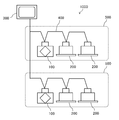
- FIG. 11 is a diagram showing a configuration of an air conditioning system 1000 including the heat exchange ventilation device 100 according to the fourth embodiment.
- FIG. 12 is a flowchart showing the operation of the control device 300 according to the fourth embodiment.
- the air conditioning system 1000 includes a heat exchange ventilation device 100, an air conditioning device 200, and a control device 300.
- FIG. 11 shows an air conditioning system 1000 in which one heat exchange ventilation device 100 and two air conditioning devices 200 are installed in each of the two ventilation spaces 500.
- the ventilation space 500 and the heat exchange ventilation device 100 are shown.
- the number of air conditioners 200 is an example and can be changed as appropriate.
- the air conditioned device 200 can operate, for example, a cooling operation, a heating operation, and a dehumidifying operation, and sends conditioned air into the room. Further, the heat exchange ventilation device 100 and the air conditioner 200 are connected by the communication means 400, and the operating state can be transmitted and received to each other via the communication means 400. Further, the control device 300 is a centralized control device that controls the operation of the heat exchange ventilation device 100 and the air conditioner 200, and is connected to the heat exchange ventilation device 100 and the air conditioner 200 by the communication means 400.
- the heat exchange ventilation device 100 is dried. Even if the exhaust blower 3 is operated in the operating state, the total heat exchanger 4 may not be sufficiently dried.
- control device 300 starts the operation of the exhaust blower 3 in the dry operation state
- the air conditioner 200 installed in the same ventilation space 500 as the heat exchange ventilation device 100 starts the dehumidification operation. Control.
- the operation of the control device 300 of the fourth embodiment is the same as the operation of the control device 8 of the first embodiment.
- the fourth embodiment is different from the first embodiment in that steps S41 to S43 are added between steps S6 and S9.
- step S6 when the state in the stop mode is changed from the standby state to the dry operation state and the operation of the exhaust blower 3 is started, the process proceeds to step S41.
- step S41 the control device 300 determines whether or not the humidity RH RA of the air in the ventilation space 500 is larger than the preset threshold value RHc.
- the heat exchange ventilation device 100 of the fourth embodiment has a second exhaust humidity that detects the humidity RH RA of the air on the indoor side of the total heat exchanger 4 in the exhaust air passage 15 as in the third embodiment.
- a sensor 17 is provided, and the humidity RH RA of the air in the ventilation space 500 is detected by the second exhaust humidity sensor 17.
- the indoor humidity sensor provided in the air conditioner 200 may be used to detect the humidity RH RA of the air in the ventilation space 500. ..
- step S41 when the control device 300 determines that the indoor humidity RH RA is larger than the preset threshold value RHc, the process proceeds to step S42, and the air conditioning device 300 is installed in the same ventilation space 500 as the heat exchange ventilation device 100. The dehumidifying operation of the device 200 is started.
- step S41 when the control device 300 determines that the indoor humidity RH RA is equal to or less than a preset threshold value RHc, the control device 300 proceeds to step S43.
- step S43 the control device 300 stopped the dehumidifying operation when the air conditioning device 200 was performing the dehumidifying operation, and stopped the dehumidifying operation when the air conditioning device 200 was not performing the dehumidifying operation. Maintain the state.
- the air conditioning system 1000 of the fourth embodiment when the humidity detected by the exhaust humidity detecting means becomes equal to or higher than the threshold value while the operation of the air supply blower 2 and the exhaust blower 3 is stopped, the exhaust blower At the same time as starting the operation of No. 3, the dehumidifying operation of the air conditioner 200 is started. As a result, the humidity in the ventilation space 500 is reduced, so that the indoor air with reduced humidity can be sent to the total heat exchanger 4, and the drying of the total heat exchanger 4 can be promoted.
- the threshold value RHc used in step S41 is set to a value as high as possible, specifically, the upper limit of the indoor humidity that has the effect of drying the total heat exchanger 4. Is good.
- the heat exchange ventilation device 100 may include a quick-drying mode in which the total heat exchanger 4 is quickly dried.
- the quick-drying mode is a mode in which the air conditioner 200 performs a dehumidifying operation regardless of the humidity of the air in the ventilation space 500. That is, if the quick-drying mode is permitted by the remote controller 9, the control device 8 does not determine in step S41 whether or not the indoor humidity RH RA is larger than the threshold value RHc, and proceeds to step S42 to proceed to the air conditioner. Let 200 perform the dehumidifying operation, and if the quick-drying mode is not permitted, the process proceeds to step S43 so that the dehumidifying operation is not performed.
- the air conditioner 200 is made to perform the dehumidifying operation, but the air conditioner 200 is made to perform the heating operation to raise the room temperature, thereby lowering the relative humidity and reducing the room air. It may be dried.
- steps S41 to S43 are added between steps S6 and S9 of the first embodiment, but steps S6 and S9 of the second or third embodiment Steps S41 to S43 may be added between the two.
- control device 300 controls according to the flowchart of FIG. 12, but the control device 8 included in the heat exchange ventilation device 100 controls the heat exchange ventilation device 100 and the air conditioning according to the flowchart of FIG. The device 200 may be controlled.
- FIG. 13 is a schematic view showing the configuration of the heat exchange ventilation device 100 according to the modified example of the fourth embodiment, and is a diagram showing a state during the heat exchange ventilation operation.
- an air conditioning coil 18 for dehumidifying the air supply airflow is provided on the indoor side of the total heat exchanger 4 in the air supply air passage 14, that is, between the total heat exchanger 4 and the air supply outlet 12. You may.
- the control device 300 of the exhaust blower 3 At the same time as starting the operation, the operation of the air conditioning coil 18 is started.
- the outdoor air dehumidified by the air conditioning coil 18 is sent to the ventilation space 500, so that the air in the ventilation space 500 can be dried.
- the operation of the air supply blower 2 may be started at the same time. Further, since it is considered that the outdoor air is taken into the room through the air supply air passage 14 due to the negative pressure in the room due to the operation of the exhaust blower 3, the air supply blower 2 may remain stopped.
- the configuration shown in the above-described embodiment shows an example of the present disclosure, can be combined with another known technique, and a part of the configuration is omitted without departing from the gist of the present disclosure. Or it can be changed.
- the heat exchange ventilation device 100 of the first embodiment includes a first exhaust humidity sensor 6 as an exhaust humidity detecting means for detecting the humidity of the air in the exhaust air passage 15, but the exhaust humidity detecting means is
- the second exhaust humidity sensor 17 may be used to detect the humidity of the air inside the room rather than the total heat exchanger 4 in the exhaust air passage 15.
- the humidity of the air inside the exhaust air passage 15 is equal to or higher than the first threshold value RHa, the high humidity outdoor air invades the exhaust air passage 15. Therefore, it can be determined that the total heat exchanger 4 is exposed to the high humidity outdoor air in both the supply air passage 14 and the exhaust air passage 15. Further, since the humidity of the air inside the exhaust air passage 15 on the indoor side of the total heat exchanger 4 is detected, it is more likely that the high humidity outdoor air actually flows back into the room through the total heat exchanger 4. It can be detected reliably.
- the exhaust humidity detecting means may be a sensor that detects the humidity of the air in the exhaust air passage 15 in the total heat exchanger 4. Even in this case, if the humidity of the air in the exhaust air passage 15 in the total heat exchanger 4 is equal to or higher than the first threshold value RHa, it is considered that the high humidity outdoor air has invaded the exhaust air passage 15. Therefore, it can be determined that the total heat exchanger 4 is exposed to the high humidity outdoor air in both the supply air passage 14 and the exhaust air passage 15. Further, since the humidity of the air in the exhaust air passage 15 in the total heat exchanger 4 is detected, it is possible to more reliably detect that the total heat exchanger 4 is actually exposed to the high humidity outdoor air. ..
- the exhaust humidity detecting means is other than the first exhaust humidity sensor 6, if the exhaust humidity detecting means for detecting the humidity of the air in the exhaust air passage 15 is provided, it is used for air supply.
- the effect of the first embodiment is obtained by starting the operation of the exhaust blower 3 when the humidity detected by the exhaust humidity detecting means becomes equal to or higher than the threshold value while the blower 2 and the exhaust blower 3 are stopped. Be done.
- the exhaust humidity detecting means provided in the heat exchange ventilation device 100 of the second embodiment is not limited to the first exhaust humidity sensor 6 as in the first embodiment, and can detect the humidity of the air in the exhaust air passage 15. Anything is fine.
- the air supply / humidity detecting means of the heat exchange ventilation device 100 is not limited to the first air supply / humidity sensor 5, and may be any one capable of detecting the humidity of the air in the air supply air passage 14. That is, the heat exchange ventilation device 100 detects the humidity of the air indoors from the total heat exchanger 4 in the air supply air passage 14 instead of the first air supply humidity sensor 5 as the air supply humidity detecting means. It may be provided with a sensor for detecting the humidity of the air in the air supply air passage 14 in the total heat exchanger 4.
- the heat exchange ventilation device 100 provided with the air passage switching damper 7 has been described as an example, but the heat exchange ventilation device 100 not provided with the air passage switching damper 7 may be used. Even in this case, the total heat exchanger 4 is exposed to high humidity outdoor air in both the air supply air passage 14 and the exhaust air passage 15 while the operations of the air supply blower 2 and the exhaust air blower 3 are stopped. When the operation of the exhaust blower 3 is started when the conditions are met, relatively dry indoor air passes through the total heat exchanger 4, so that the generation of drain water in the total heat exchanger 4 is suppressed. can do.
- the heat exchange ventilator according to the present disclosure is useful in that it can prevent the generation of drain water in the total heat exchanger, and is suitable for the heat exchange ventilator that controls the blower using humidity information.
- 1 Casing 2 Air supply blower, 3 Exhaust blower, 4 Total heat exchanger, 5 1st air supply / humidity sensor, 6 1st exhaust humidity sensor, 7 Air passage switching damper, 8 Control device, 9 Remote control, 10 air supply air inlet, 11 exhaust air outlet, 12 air supply air outlet, 13 exhaust air inlet, 14 air supply air passage, 15 exhaust air passage, 16 bypass air passage, 17 second exhaust humidity sensor, 18 air conditioning coil, 21 processor, 22 memory, 41 partition member, 42 interval holding member, 100 heat exchange ventilation device, 200 air conditioner, 300 control device, 400 communication means, 500 ventilation space, 1000 air conditioning system.
Landscapes
- Engineering & Computer Science (AREA)
- Chemical & Material Sciences (AREA)
- Combustion & Propulsion (AREA)
- Mechanical Engineering (AREA)
- General Engineering & Computer Science (AREA)
- Ventilation (AREA)
- Air Conditioning Control Device (AREA)
Priority Applications (2)
| Application Number | Priority Date | Filing Date | Title |
|---|---|---|---|
| JP2022513713A JP7380849B2 (ja) | 2020-04-06 | 2020-04-06 | 熱交換換気装置及び空気調和システム |
| PCT/JP2020/015501 WO2021205505A1 (ja) | 2020-04-06 | 2020-04-06 | 熱交換換気装置及び空気調和システム |
Applications Claiming Priority (1)
| Application Number | Priority Date | Filing Date | Title |
|---|---|---|---|
| PCT/JP2020/015501 WO2021205505A1 (ja) | 2020-04-06 | 2020-04-06 | 熱交換換気装置及び空気調和システム |
Publications (1)
| Publication Number | Publication Date |
|---|---|
| WO2021205505A1 true WO2021205505A1 (ja) | 2021-10-14 |
Family
ID=78022451
Family Applications (1)
| Application Number | Title | Priority Date | Filing Date |
|---|---|---|---|
| PCT/JP2020/015501 Ceased WO2021205505A1 (ja) | 2020-04-06 | 2020-04-06 | 熱交換換気装置及び空気調和システム |
Country Status (2)
| Country | Link |
|---|---|
| JP (1) | JP7380849B2 (https=) |
| WO (1) | WO2021205505A1 (https=) |
Cited By (1)
| Publication number | Priority date | Publication date | Assignee | Title |
|---|---|---|---|---|
| CN118408240A (zh) * | 2024-04-08 | 2024-07-30 | 中信建筑设计研究总院有限公司 | 一种外冷型温湿分控新风机组 |
Families Citing this family (1)
| Publication number | Priority date | Publication date | Assignee | Title |
|---|---|---|---|---|
| EP4343221A4 (en) | 2021-11-19 | 2024-11-27 | Samsung Electronics Co., Ltd. | Ventilation apparatus and method for controlling same |
Citations (6)
| Publication number | Priority date | Publication date | Assignee | Title |
|---|---|---|---|---|
| JPS58110731U (ja) * | 1982-01-21 | 1983-07-28 | 三菱電機株式会社 | 空調換気扇 |
| JPS60182630U (ja) * | 1984-05-15 | 1985-12-04 | 三菱電機株式会社 | 空調換気扇 |
| JP2008309381A (ja) * | 2007-06-13 | 2008-12-25 | Mitsubishi Electric Corp | 熱交換換気装置 |
| JP2009063278A (ja) * | 2007-09-10 | 2009-03-26 | Panasonic Corp | 換気空調装置 |
| JP2011064407A (ja) * | 2009-09-17 | 2011-03-31 | Mitsubishi Electric Corp | 空気調和装置 |
| JP2014163551A (ja) * | 2013-02-22 | 2014-09-08 | Mitsubishi Electric Corp | 熱交換換気装置 |
-
2020
- 2020-04-06 WO PCT/JP2020/015501 patent/WO2021205505A1/ja not_active Ceased
- 2020-04-06 JP JP2022513713A patent/JP7380849B2/ja active Active
Patent Citations (6)
| Publication number | Priority date | Publication date | Assignee | Title |
|---|---|---|---|---|
| JPS58110731U (ja) * | 1982-01-21 | 1983-07-28 | 三菱電機株式会社 | 空調換気扇 |
| JPS60182630U (ja) * | 1984-05-15 | 1985-12-04 | 三菱電機株式会社 | 空調換気扇 |
| JP2008309381A (ja) * | 2007-06-13 | 2008-12-25 | Mitsubishi Electric Corp | 熱交換換気装置 |
| JP2009063278A (ja) * | 2007-09-10 | 2009-03-26 | Panasonic Corp | 換気空調装置 |
| JP2011064407A (ja) * | 2009-09-17 | 2011-03-31 | Mitsubishi Electric Corp | 空気調和装置 |
| JP2014163551A (ja) * | 2013-02-22 | 2014-09-08 | Mitsubishi Electric Corp | 熱交換換気装置 |
Cited By (1)
| Publication number | Priority date | Publication date | Assignee | Title |
|---|---|---|---|---|
| CN118408240A (zh) * | 2024-04-08 | 2024-07-30 | 中信建筑设计研究总院有限公司 | 一种外冷型温湿分控新风机组 |
Also Published As
| Publication number | Publication date |
|---|---|
| JPWO2021205505A1 (https=) | 2021-10-14 |
| JP7380849B2 (ja) | 2023-11-15 |
Similar Documents
| Publication | Publication Date | Title |
|---|---|---|
| JP3835413B2 (ja) | 除湿空調装置 | |
| JP6253459B2 (ja) | 空調用換気装置 | |
| JP4565936B2 (ja) | 空気調和装置 | |
| JP5850487B2 (ja) | デシカント換気扇 | |
| WO2018056191A1 (ja) | 熱交換形換気装置 | |
| WO2020003446A1 (ja) | 空気調和装置 | |
| WO2021205505A1 (ja) | 熱交換換気装置及び空気調和システム | |
| JP5359170B2 (ja) | 空調装置 | |
| CN103375859B (zh) | 空调换气装置 | |
| JP6861824B2 (ja) | 熱交換換気装置 | |
| JP4906493B2 (ja) | デシカント空調機及びその防露装置 | |
| JP6656043B2 (ja) | 換気システムおよび換気装置 | |
| JP2006046731A (ja) | 換気システムと住宅構造 | |
| JP3008941B1 (ja) | 調湿換気装置 | |
| KR100430002B1 (ko) | 욕실용 공조기의 운전제어방법 | |
| JP4675075B2 (ja) | 空気調和装置及び空気調和装置の制御方法 | |
| JPH0718570B2 (ja) | 空気浄化換気空調装置及び該装置の制御方式 | |
| KR20060089432A (ko) | 쾌적한 냉방을 위한 제습운전이 가능한 에어컨과 그에사용되는 실내기 및 제습운전 방법 | |
| JP2000179919A (ja) | 空気調和機 | |
| JP2013145113A (ja) | 空調装置 | |
| JP7570522B2 (ja) | 熱交換換気装置 | |
| JP6745895B2 (ja) | 空調システム | |
| JP7197811B2 (ja) | 換気システム | |
| JPS642113Y2 (https=) | ||
| JP7457257B2 (ja) | 換気装置 |
Legal Events
| Date | Code | Title | Description |
|---|---|---|---|
| 121 | Ep: the epo has been informed by wipo that ep was designated in this application |
Ref document number: 20930230 Country of ref document: EP Kind code of ref document: A1 |
|
| ENP | Entry into the national phase |
Ref document number: 2022513713 Country of ref document: JP Kind code of ref document: A |
|
| NENP | Non-entry into the national phase |
Ref country code: DE |
|
| 122 | Ep: pct application non-entry in european phase |
Ref document number: 20930230 Country of ref document: EP Kind code of ref document: A1 |