WO2021201138A1 - 光変換装置および照明システム - Google Patents
光変換装置および照明システム Download PDFInfo
- Publication number
- WO2021201138A1 WO2021201138A1 PCT/JP2021/013941 JP2021013941W WO2021201138A1 WO 2021201138 A1 WO2021201138 A1 WO 2021201138A1 JP 2021013941 W JP2021013941 W JP 2021013941W WO 2021201138 A1 WO2021201138 A1 WO 2021201138A1
- Authority
- WO
- WIPO (PCT)
- Prior art keywords
- optical
- conversion device
- phosphor
- unit
- fluorescence
- Prior art date
Links
- 238000006243 chemical reaction Methods 0.000 title claims abstract description 350
- 230000003287 optical effect Effects 0.000 title claims abstract description 277
- 238000005286 illumination Methods 0.000 title description 19
- OAICVXFJPJFONN-UHFFFAOYSA-N Phosphorus Chemical group [P] OAICVXFJPJFONN-UHFFFAOYSA-N 0.000 claims abstract description 341
- 230000005284 excitation Effects 0.000 claims abstract description 138
- 238000001228 spectrum Methods 0.000 claims abstract description 58
- 230000004044 response Effects 0.000 claims abstract description 33
- 230000005540 biological transmission Effects 0.000 claims description 78
- 239000000835 fiber Substances 0.000 claims description 66
- 230000007246 mechanism Effects 0.000 claims description 61
- 230000005855 radiation Effects 0.000 claims description 25
- 230000033001 locomotion Effects 0.000 description 41
- 239000000463 material Substances 0.000 description 21
- 238000010586 diagram Methods 0.000 description 14
- 230000001276 controlling effect Effects 0.000 description 9
- 230000008859 change Effects 0.000 description 8
- 239000007769 metal material Substances 0.000 description 8
- 239000008188 pellet Substances 0.000 description 8
- 229910052712 strontium Inorganic materials 0.000 description 7
- 239000000758 substrate Substances 0.000 description 7
- 239000011521 glass Substances 0.000 description 6
- 239000002245 particle Substances 0.000 description 6
- 239000000126 substance Substances 0.000 description 6
- 239000012780 transparent material Substances 0.000 description 6
- 229910052788 barium Inorganic materials 0.000 description 5
- 239000011651 chromium Substances 0.000 description 5
- 239000010949 copper Substances 0.000 description 5
- 239000011777 magnesium Substances 0.000 description 5
- 239000013307 optical fiber Substances 0.000 description 5
- 229910052782 aluminium Inorganic materials 0.000 description 4
- 229910052804 chromium Inorganic materials 0.000 description 4
- 229910052749 magnesium Inorganic materials 0.000 description 4
- 238000002844 melting Methods 0.000 description 4
- 230000008018 melting Effects 0.000 description 4
- 229910052693 Europium Inorganic materials 0.000 description 3
- XEEYBQQBJWHFJM-UHFFFAOYSA-N Iron Chemical compound [Fe] XEEYBQQBJWHFJM-UHFFFAOYSA-N 0.000 description 3
- 229910052802 copper Inorganic materials 0.000 description 3
- 230000001747 exhibiting effect Effects 0.000 description 3
- 238000000034 method Methods 0.000 description 3
- 229910052760 oxygen Inorganic materials 0.000 description 3
- 229910052709 silver Inorganic materials 0.000 description 3
- CPLXHLVBOLITMK-UHFFFAOYSA-N Magnesium oxide Chemical compound [Mg]=O CPLXHLVBOLITMK-UHFFFAOYSA-N 0.000 description 2
- 229910004283 SiO 4 Inorganic materials 0.000 description 2
- VYPSYNLAJGMNEJ-UHFFFAOYSA-N Silicium dioxide Chemical compound O=[Si]=O VYPSYNLAJGMNEJ-UHFFFAOYSA-N 0.000 description 2
- 229910004122 SrSi Inorganic materials 0.000 description 2
- 229910052790 beryllium Inorganic materials 0.000 description 2
- 229910052791 calcium Inorganic materials 0.000 description 2
- 238000005266 casting Methods 0.000 description 2
- 238000005253 cladding Methods 0.000 description 2
- 239000013078 crystal Substances 0.000 description 2
- 238000004512 die casting Methods 0.000 description 2
- 239000010408 film Substances 0.000 description 2
- 230000006870 function Effects 0.000 description 2
- 239000010931 gold Substances 0.000 description 2
- 230000006872 improvement Effects 0.000 description 2
- 229910052809 inorganic oxide Inorganic materials 0.000 description 2
- 229910052742 iron Inorganic materials 0.000 description 2
- 239000000203 mixture Substances 0.000 description 2
- 238000000465 moulding Methods 0.000 description 2
- 230000002093 peripheral effect Effects 0.000 description 2
- 239000011347 resin Substances 0.000 description 2
- 229920005989 resin Polymers 0.000 description 2
- OGIDPMRJRNCKJF-UHFFFAOYSA-N titanium oxide Inorganic materials [Ti]=O OGIDPMRJRNCKJF-UHFFFAOYSA-N 0.000 description 2
- 229910018072 Al 2 O 3 Inorganic materials 0.000 description 1
- PIGFYZPCRLYGLF-UHFFFAOYSA-N Aluminum nitride Chemical compound [Al]#N PIGFYZPCRLYGLF-UHFFFAOYSA-N 0.000 description 1
- OKTJSMMVPCPJKN-UHFFFAOYSA-N Carbon Chemical compound [C] OKTJSMMVPCPJKN-UHFFFAOYSA-N 0.000 description 1
- VYZAMTAEIAYCRO-UHFFFAOYSA-N Chromium Chemical compound [Cr] VYZAMTAEIAYCRO-UHFFFAOYSA-N 0.000 description 1
- RYGMFSIKBFXOCR-UHFFFAOYSA-N Copper Chemical compound [Cu] RYGMFSIKBFXOCR-UHFFFAOYSA-N 0.000 description 1
- JMASRVWKEDWRBT-UHFFFAOYSA-N Gallium nitride Chemical compound [Ga]#N JMASRVWKEDWRBT-UHFFFAOYSA-N 0.000 description 1
- FYYHWMGAXLPEAU-UHFFFAOYSA-N Magnesium Chemical compound [Mg] FYYHWMGAXLPEAU-UHFFFAOYSA-N 0.000 description 1
- 229910020068 MgAl Inorganic materials 0.000 description 1
- ZOKXTWBITQBERF-UHFFFAOYSA-N Molybdenum Chemical compound [Mo] ZOKXTWBITQBERF-UHFFFAOYSA-N 0.000 description 1
- 229910052581 Si3N4 Inorganic materials 0.000 description 1
- 229910003564 SiAlON Inorganic materials 0.000 description 1
- 229910004298 SiO 2 Inorganic materials 0.000 description 1
- BQCADISMDOOEFD-UHFFFAOYSA-N Silver Chemical compound [Ag] BQCADISMDOOEFD-UHFFFAOYSA-N 0.000 description 1
- GWEVSGVZZGPLCZ-UHFFFAOYSA-N Titan oxide Chemical compound O=[Ti]=O GWEVSGVZZGPLCZ-UHFFFAOYSA-N 0.000 description 1
- 229910045601 alloy Inorganic materials 0.000 description 1
- 239000000956 alloy Substances 0.000 description 1
- XAGFODPZIPBFFR-UHFFFAOYSA-N aluminium Chemical compound [Al] XAGFODPZIPBFFR-UHFFFAOYSA-N 0.000 description 1
- QVGXLLKOCUKJST-UHFFFAOYSA-N atomic oxygen Chemical compound [O] QVGXLLKOCUKJST-UHFFFAOYSA-N 0.000 description 1
- 238000005452 bending Methods 0.000 description 1
- ATBAMAFKBVZNFJ-UHFFFAOYSA-N beryllium atom Chemical compound [Be] ATBAMAFKBVZNFJ-UHFFFAOYSA-N 0.000 description 1
- 210000000746 body region Anatomy 0.000 description 1
- 229910052799 carbon Inorganic materials 0.000 description 1
- 229910017052 cobalt Inorganic materials 0.000 description 1
- 239000010941 cobalt Substances 0.000 description 1
- GUTLYIVDDKVIGB-UHFFFAOYSA-N cobalt atom Chemical compound [Co] GUTLYIVDDKVIGB-UHFFFAOYSA-N 0.000 description 1
- 239000003086 colorant Substances 0.000 description 1
- 230000002596 correlated effect Effects 0.000 description 1
- 230000000875 corresponding effect Effects 0.000 description 1
- 239000002178 crystalline material Substances 0.000 description 1
- 230000007423 decrease Effects 0.000 description 1
- 230000003247 decreasing effect Effects 0.000 description 1
- 238000001514 detection method Methods 0.000 description 1
- 230000004907 flux Effects 0.000 description 1
- PCHJSUWPFVWCPO-UHFFFAOYSA-N gold Chemical compound [Au] PCHJSUWPFVWCPO-UHFFFAOYSA-N 0.000 description 1
- 229910052737 gold Inorganic materials 0.000 description 1
- 230000001678 irradiating effect Effects 0.000 description 1
- ORUIBWPALBXDOA-UHFFFAOYSA-L magnesium fluoride Chemical compound [F-].[F-].[Mg+2] ORUIBWPALBXDOA-UHFFFAOYSA-L 0.000 description 1
- 229910001635 magnesium fluoride Inorganic materials 0.000 description 1
- 239000000395 magnesium oxide Substances 0.000 description 1
- 229910044991 metal oxide Inorganic materials 0.000 description 1
- 150000004706 metal oxides Chemical class 0.000 description 1
- 238000012986 modification Methods 0.000 description 1
- 230000004048 modification Effects 0.000 description 1
- 229910052750 molybdenum Inorganic materials 0.000 description 1
- 239000011733 molybdenum Substances 0.000 description 1
- ZKATWMILCYLAPD-UHFFFAOYSA-N niobium pentoxide Inorganic materials O=[Nb](=O)O[Nb](=O)=O ZKATWMILCYLAPD-UHFFFAOYSA-N 0.000 description 1
- URLJKFSTXLNXLG-UHFFFAOYSA-N niobium(5+);oxygen(2-) Chemical compound [O-2].[O-2].[O-2].[O-2].[O-2].[Nb+5].[Nb+5] URLJKFSTXLNXLG-UHFFFAOYSA-N 0.000 description 1
- TWNQGVIAIRXVLR-UHFFFAOYSA-N oxo(oxoalumanyloxy)alumane Chemical compound O=[Al]O[Al]=O TWNQGVIAIRXVLR-UHFFFAOYSA-N 0.000 description 1
- 239000001301 oxygen Substances 0.000 description 1
- BPUBBGLMJRNUCC-UHFFFAOYSA-N oxygen(2-);tantalum(5+) Chemical compound [O-2].[O-2].[O-2].[O-2].[O-2].[Ta+5].[Ta+5] BPUBBGLMJRNUCC-UHFFFAOYSA-N 0.000 description 1
- 238000007747 plating Methods 0.000 description 1
- 229910052594 sapphire Inorganic materials 0.000 description 1
- 239000010980 sapphire Substances 0.000 description 1
- 239000004065 semiconductor Substances 0.000 description 1
- HBMJWWWQQXIZIP-UHFFFAOYSA-N silicon carbide Chemical compound [Si+]#[C-] HBMJWWWQQXIZIP-UHFFFAOYSA-N 0.000 description 1
- 239000000377 silicon dioxide Substances 0.000 description 1
- 235000012239 silicon dioxide Nutrition 0.000 description 1
- HQVNEWCFYHHQES-UHFFFAOYSA-N silicon nitride Chemical compound N12[Si]34N5[Si]62N3[Si]51N64 HQVNEWCFYHHQES-UHFFFAOYSA-N 0.000 description 1
- 239000004332 silver Substances 0.000 description 1
- 239000010944 silver (metal) Substances 0.000 description 1
- 239000007787 solid Substances 0.000 description 1
- PBCFLUZVCVVTBY-UHFFFAOYSA-N tantalum pentoxide Inorganic materials O=[Ta](=O)O[Ta](=O)=O PBCFLUZVCVVTBY-UHFFFAOYSA-N 0.000 description 1
- 239000010409 thin film Substances 0.000 description 1
- WFKWXMTUELFFGS-UHFFFAOYSA-N tungsten Chemical compound [W] WFKWXMTUELFFGS-UHFFFAOYSA-N 0.000 description 1
- 229910052721 tungsten Inorganic materials 0.000 description 1
- 239000010937 tungsten Substances 0.000 description 1
- 238000007740 vapor deposition Methods 0.000 description 1
- 229910052725 zinc Inorganic materials 0.000 description 1
Images


Classifications
-
- H—ELECTRICITY
- H01—ELECTRIC ELEMENTS
- H01L—SEMICONDUCTOR DEVICES NOT COVERED BY CLASS H10
- H01L33/00—Semiconductor devices having potential barriers specially adapted for light emission; Processes or apparatus specially adapted for the manufacture or treatment thereof or of parts thereof; Details thereof
- H01L33/48—Semiconductor devices having potential barriers specially adapted for light emission; Processes or apparatus specially adapted for the manufacture or treatment thereof or of parts thereof; Details thereof characterised by the semiconductor body packages
- H01L33/50—Wavelength conversion elements
- H01L33/505—Wavelength conversion elements characterised by the shape, e.g. plate or foil
-
- G—PHYSICS
- G02—OPTICS
- G02B—OPTICAL ELEMENTS, SYSTEMS OR APPARATUS
- G02B6/00—Light guides; Structural details of arrangements comprising light guides and other optical elements, e.g. couplings
- G02B6/0001—Light guides; Structural details of arrangements comprising light guides and other optical elements, e.g. couplings specially adapted for lighting devices or systems
- G02B6/0005—Light guides; Structural details of arrangements comprising light guides and other optical elements, e.g. couplings specially adapted for lighting devices or systems the light guides being of the fibre type
- G02B6/0008—Light guides; Structural details of arrangements comprising light guides and other optical elements, e.g. couplings specially adapted for lighting devices or systems the light guides being of the fibre type the light being emitted at the end of the fibre
-
- F—MECHANICAL ENGINEERING; LIGHTING; HEATING; WEAPONS; BLASTING
- F21—LIGHTING
- F21V—FUNCTIONAL FEATURES OR DETAILS OF LIGHTING DEVICES OR SYSTEMS THEREOF; STRUCTURAL COMBINATIONS OF LIGHTING DEVICES WITH OTHER ARTICLES, NOT OTHERWISE PROVIDED FOR
- F21V7/00—Reflectors for light sources
- F21V7/04—Optical design
- F21V7/08—Optical design with elliptical curvature
-
- F—MECHANICAL ENGINEERING; LIGHTING; HEATING; WEAPONS; BLASTING
- F21—LIGHTING
- F21V—FUNCTIONAL FEATURES OR DETAILS OF LIGHTING DEVICES OR SYSTEMS THEREOF; STRUCTURAL COMBINATIONS OF LIGHTING DEVICES WITH OTHER ARTICLES, NOT OTHERWISE PROVIDED FOR
- F21V7/00—Reflectors for light sources
- F21V7/22—Reflectors for light sources characterised by materials, surface treatments or coatings, e.g. dichroic reflectors
- F21V7/24—Reflectors for light sources characterised by materials, surface treatments or coatings, e.g. dichroic reflectors characterised by the material
- F21V7/26—Reflectors for light sources characterised by materials, surface treatments or coatings, e.g. dichroic reflectors characterised by the material the material comprising photoluminescent substances
-
- G—PHYSICS
- G02—OPTICS
- G02B—OPTICAL ELEMENTS, SYSTEMS OR APPARATUS
- G02B26/00—Optical devices or arrangements for the control of light using movable or deformable optical elements
- G02B26/007—Optical devices or arrangements for the control of light using movable or deformable optical elements the movable or deformable optical element controlling the colour, i.e. a spectral characteristic, of the light
- G02B26/008—Optical devices or arrangements for the control of light using movable or deformable optical elements the movable or deformable optical element controlling the colour, i.e. a spectral characteristic, of the light in the form of devices for effecting sequential colour changes, e.g. colour wheels
-
- H—ELECTRICITY
- H01—ELECTRIC ELEMENTS
- H01L—SEMICONDUCTOR DEVICES NOT COVERED BY CLASS H10
- H01L33/00—Semiconductor devices having potential barriers specially adapted for light emission; Processes or apparatus specially adapted for the manufacture or treatment thereof or of parts thereof; Details thereof
- H01L33/48—Semiconductor devices having potential barriers specially adapted for light emission; Processes or apparatus specially adapted for the manufacture or treatment thereof or of parts thereof; Details thereof characterised by the semiconductor body packages
- H01L33/50—Wavelength conversion elements
- H01L33/501—Wavelength conversion elements characterised by the materials, e.g. binder
- H01L33/502—Wavelength conversion materials
-
- H—ELECTRICITY
- H01—ELECTRIC ELEMENTS
- H01L—SEMICONDUCTOR DEVICES NOT COVERED BY CLASS H10
- H01L33/00—Semiconductor devices having potential barriers specially adapted for light emission; Processes or apparatus specially adapted for the manufacture or treatment thereof or of parts thereof; Details thereof
- H01L33/48—Semiconductor devices having potential barriers specially adapted for light emission; Processes or apparatus specially adapted for the manufacture or treatment thereof or of parts thereof; Details thereof characterised by the semiconductor body packages
- H01L33/58—Optical field-shaping elements
- H01L33/60—Reflective elements
-
- F—MECHANICAL ENGINEERING; LIGHTING; HEATING; WEAPONS; BLASTING
- F21—LIGHTING
- F21V—FUNCTIONAL FEATURES OR DETAILS OF LIGHTING DEVICES OR SYSTEMS THEREOF; STRUCTURAL COMBINATIONS OF LIGHTING DEVICES WITH OTHER ARTICLES, NOT OTHERWISE PROVIDED FOR
- F21V29/00—Protecting lighting devices from thermal damage; Cooling or heating arrangements specially adapted for lighting devices or systems
- F21V29/50—Cooling arrangements
- F21V29/502—Cooling arrangements characterised by the adaptation for cooling of specific components
-
- F—MECHANICAL ENGINEERING; LIGHTING; HEATING; WEAPONS; BLASTING
- F21—LIGHTING
- F21Y—INDEXING SCHEME ASSOCIATED WITH SUBCLASSES F21K, F21L, F21S and F21V, RELATING TO THE FORM OR THE KIND OF THE LIGHT SOURCES OR OF THE COLOUR OF THE LIGHT EMITTED
- F21Y2115/00—Light-generating elements of semiconductor light sources
- F21Y2115/10—Light-emitting diodes [LED]
-
- F—MECHANICAL ENGINEERING; LIGHTING; HEATING; WEAPONS; BLASTING
- F21—LIGHTING
- F21Y—INDEXING SCHEME ASSOCIATED WITH SUBCLASSES F21K, F21L, F21S and F21V, RELATING TO THE FORM OR THE KIND OF THE LIGHT SOURCES OR OF THE COLOUR OF THE LIGHT EMITTED
- F21Y2115/00—Light-generating elements of semiconductor light sources
- F21Y2115/30—Semiconductor lasers
Definitions
- This disclosure relates to an optical converter and a lighting system.
- a device that emits pseudo white light by converting monochromatic excitation light emitted from a light emitting element into light having a different wavelength depending on a fluorescent substance is known (for example, the description of Japanese Patent Application Laid-Open No. 2011-181739. reference).
- the light converter and lighting system will be disclosed.
- the optical conversion device includes a wavelength conversion unit in which a plurality of phosphor regions are arranged, a drive unit, and a control unit.
- the plurality of phosphor regions include a first phosphor region that emits fluorescence having a first wavelength spectrum in response to irradiation with excitation light, and a second wavelength different from the first wavelength spectrum in response to irradiation with the excitation light. Includes a second fluorescent region that emits fluorescence with a spectrum.
- the driving unit changes the irradiated region to which the excitation light is irradiated in the plurality of phosphor regions.
- the control unit sets the irradiated region in the plurality of phosphor regions by changing the irradiated region in the plurality of phosphor regions by driving the driving unit and stopping the driving of the driving unit.
- the drive unit is controlled so as to.
- One aspect of the lighting system includes a light emitting module, a first optical transmission fiber, a repeater, a second optical transmission fiber, and an optical radiation module.
- the light emitting module emits excitation light.
- the first optical transmission fiber transmits the excitation light from the light emitting module.
- the repeater includes the optical conversion device of the above aspect.
- the second optical transmission fiber transmits the fluorescence from the repeater.
- the light emitting module radiates the fluorescence transmitted by the second optical transmission fiber to the external space.
- FIG. 1 is a diagram showing an outline of an example of a lighting system according to the first embodiment.
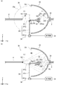
- FIG. 2A is a cross-sectional view schematically showing a configuration example of the optical conversion device according to the first embodiment.
- FIG. 2B is a cross-sectional view schematically showing how the excitation light is converted into fluorescence in one configuration example of the optical conversion device according to the first embodiment.
- 3A to 3C are diagrams showing an example of a plurality of phosphor regions and an example of changing the irradiated region in the wavelength conversion unit.
- 4 (a) to 4 (c) are diagrams illustrating the movement of a plurality of phosphor regions and irradiated regions in the wavelength conversion unit, respectively.
- FIG. 5 (a) to 5 (c) are diagrams showing an example of a plurality of phosphor regions and an example of changing the irradiated region in the wavelength conversion unit.
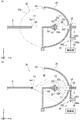
- FIG. 6A is a cross-sectional view schematically showing a configuration example of the optical conversion device according to the second embodiment.
- FIG. 6B is a cross-sectional view schematically showing how the excitation light is converted into fluorescence in one configuration example of the optical conversion device according to the second embodiment.
- 7 (a) to 7 (c) are diagrams showing an example of a plurality of phosphor regions and an example of movement of the irradiated region in the wavelength conversion unit.
- FIG. 8 (a) to 8 (c) are diagrams showing an example of a plurality of phosphor regions and an example of movement of the irradiated region in the wavelength conversion unit.
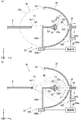
- FIG. 9A is a cross-sectional view schematically showing a first configuration example of the optical conversion device according to the third embodiment.
- FIG. 9B is a cross-sectional view schematically showing how the excitation light is converted into fluorescence in the first configuration example of the optical conversion device according to the third embodiment.
- 10 (a) to 10 (c) are diagrams showing an example of a plurality of phosphor regions and an example of changing the irradiated region in the wavelength conversion unit.
- FIG. 11A is a cross-sectional view schematically showing a second configuration example of the optical conversion device according to the third embodiment.
- FIG. 11B is a cross-sectional view schematically showing how the excitation light is converted into fluorescence in the second configuration example of the optical conversion device according to the third embodiment.
- 12 (a) to 12 (c) are diagrams showing an example of a plurality of phosphor regions and an example of changing the irradiated region in the wavelength conversion unit.
- FIG. 13A is a cross-sectional view schematically showing a first configuration example of the optical conversion device according to the fourth embodiment.
- FIG. 13B is a cross-sectional view schematically showing how the excitation light is converted into fluorescence in the first configuration example of the optical conversion device according to the fourth embodiment.
- FIG. 14A is a cross-sectional view schematically showing a second configuration example of the optical conversion device according to the fourth embodiment.
- FIG. 14B is a cross-sectional view schematically showing how the excitation light is converted into fluorescence in the second configuration example of the optical conversion device according to the fourth embodiment.
- FIG. 15A is a cross-sectional view schematically showing a first configuration example of the optical conversion device according to the fifth embodiment.
- FIG. 15B is a cross-sectional view schematically showing how the excitation light is converted into fluorescence in the first configuration example of the optical conversion device according to the fifth embodiment.
- FIG. 16A is a cross-sectional view schematically showing a second configuration example of the optical conversion device according to the fifth embodiment.
- FIG. 16B is a cross-sectional view schematically showing how the excitation light is converted into fluorescence in the second configuration example of the optical conversion device according to the fifth embodiment.
- FIG. 17 (a) to 17 (c) are diagrams illustrating the movement of a plurality of phosphor regions and irradiated regions in the wavelength conversion unit, respectively.
- FIG. 18A is a cross-sectional view schematically showing a third configuration example of the optical conversion device according to the fifth embodiment.
- FIG. 18B is a cross-sectional view schematically showing how the excitation light is converted into fluorescence in the third configuration example of the optical conversion device according to the fifth embodiment.
- 19 (a) to 19 (c) are diagrams illustrating the movement of a plurality of phosphor regions and irradiated regions in the wavelength conversion unit, respectively.
- FIG. 20A is a cross-sectional view schematically showing a fourth configuration example of the optical conversion device according to the fifth embodiment.
- FIG. 20A is a cross-sectional view schematically showing a fourth configuration example of the optical conversion device according to the fifth embodiment.
- FIG. 20B is a cross-sectional view schematically showing how the excitation light is converted into fluorescence in the fourth configuration example of the optical conversion device according to the fifth embodiment.
- 21 (a) and 21 (b) are diagrams illustrating the movement of a plurality of phosphor regions and irradiated regions in the wavelength conversion unit, respectively.
- FIG. 22A is a cross-sectional view schematically showing a first configuration example of the optical conversion device according to the sixth embodiment.
- FIG. 22B is a cross-sectional view schematically showing how the excitation light is converted into fluorescence in the first configuration example of the optical conversion device according to the sixth embodiment.
- FIG. 23A is a cross-sectional view schematically showing a second configuration example of the optical conversion device according to the sixth embodiment.
- FIG. 23B is a cross-sectional view schematically showing how the excitation light is converted into fluorescence in the second configuration example of the optical conversion device according to the sixth embodiment.
- 24 (a) to 24 (c) are diagrams showing an example of a plurality of phosphor regions and an example of changing the irradiated region in the wavelength conversion unit.
- FIG. 25A is a cross-sectional view schematically showing a third configuration example of the optical conversion device according to the sixth embodiment.
- FIG. 25B is a cross-sectional view schematically showing how the excitation light is converted into fluorescence in the third configuration example of the optical conversion device according to the sixth embodiment.
- FIG. 26A is a cross-sectional view schematically showing a fourth configuration example of the optical conversion device according to the sixth embodiment.
- FIG. 26B is a cross-sectional view schematically showing how the excitation light is converted into fluorescence in the fourth configuration example of the optical conversion device according to the sixth embodiment.
- FIG. 27 is a diagram showing an outline of an example of the lighting system according to the seventh embodiment.
- FIG. 28A is a cross-sectional view schematically showing a first configuration example of the light radiation module according to the seventh embodiment.
- FIG. 28B is a cross-sectional view schematically showing how the excitation light is converted into fluorescence in the first configuration example of the light emission module according to the seventh embodiment.
- FIG. 29A is a cross-sectional view schematically showing a second configuration example of the light radiation module according to the seventh embodiment.
- FIG. 29B is a cross-sectional view schematically showing how the excitation light is converted into fluorescence in the second configuration example of the light emission module according to the seventh embodiment.
- FIG. 30 is a diagram showing an outline of an example of the lighting system according to the eighth embodiment.
- FIG. 31A is a cross-sectional view schematically showing a configuration example of the light emitting module according to the eighth embodiment.
- FIG. 31B is a cross-sectional view schematically showing how the excitation light is converted into fluorescence in one configuration example of the light emitting module according to the eighth embodiment.
- a device that emits pseudo white light by converting monochromatic light emitted from a light emitting element into light having a different wavelength depending on a fluorescent substance is known.
- a phosphor also referred to as a mixed phosphor
- a plurality of types of fluorescent substances emitting fluorescence of a specific wavelength are mixed with excitation light emitted by a light emitting element
- a configuration that emits light having a color temperature according to the characteristics and the mixing ratio can be considered.
- the color temperature in the present specification for example, the color temperature specified in JIS Z 8725: 2015 or the correlated color temperature can be adopted.
- the color temperature of the emitted light (also referred to as the emitted light) is determined by the characteristics and mixing ratio of a plurality of types of fluorescent substances, so that the color of the emitted light cannot be adjusted.
- the first light emitting unit emits fluorescence at the first color temperature by the first mixed phosphor according to the excitation light emitted by the first light emitting element
- the second mixed phosphor responds to the excitation light emitted by the second light emitting element.
- the inventor of the present disclosure has created a technique capable of easily adjusting the color of the emitted light in the lighting system including the light conversion device and the light conversion device.
- the direction in which the fluorescence W0 is emitted from the optical converter is the ⁇ X direction.
- one direction perpendicular to the ⁇ X direction is defined as the + Y direction, and the direction orthogonal to both the ⁇ X direction and the + Y direction is defined as the + Z direction.
- FIGS. 29 (a) to 29 (b) show the housing 5b of the light radiation module 5.
- the housing 1b of the light emitting module 1 is not shown. 2 (b), 6 (b), 9 (b), 11 (b), 13 (b), 14 (b), 15 (b), 16 (b), 18 (B), FIG. 20 (b), FIG. 22 (b), FIG. 23 (b), FIG. 25 (b), FIG. 26 (b), FIG. 28 (b), FIG. 29 (b) and FIG. 31 (b).
- the direction in which the excitation light P0 travels is drawn by a two-dot chain arrow
- the outer edge of the virtual ellipsoidal surface 35e is drawn by a thin two-dot chain line.
- FIGS. 19 (a) to 19 (c), 21 (a), 21 (b) and 24 (a) to 24 (c), respectively.
- the outer edge of the irradiation region I1 is drawn by a thick two-dot chain line.
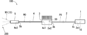
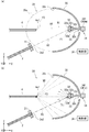
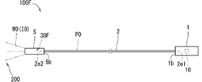
- the lighting system 100 includes, for example, a light emitting module 1, a first optical transmission fiber 2, a repeater 3, a second optical transmission fiber 4, and an optical radiation module. 5 and.
- the light emitting module 1 can emit excitation light P0, for example.
- the light emitting module 1 has a light emitting element 10.
- the light emitting element 10 includes, for example, a laser diode (LD) or a light emitting diode (LED) chip.
- LD laser diode
- LED light emitting diode
- monochromatic light such as purple, bluish purple, or blue is applied to the excitation light P0 emitted by the light emitting element 10.
- GaN gallium nitride
- nm nanometers
- the excitation light P0 emitted by the light emitting element 10 is focused toward one end (also referred to as the first incident end) 2e1 of the first optical transmission fiber 2 by an optical system for collecting light.
- the light emitting module 1 has, for example, a housing 1b containing various configurations.
- the first optical transmission fiber 2 can transmit the excitation light P0 from the light emitting module 1, for example.
- the first optical transmission fiber 2 is located from the light emitting module 1 to the repeater 3.
- the first incident end 2e1 in the longitudinal direction of the first optical transmission fiber 2 is located in the light emitting module 1, which is opposite to the first incident end 2e1 in the longitudinal direction of the first optical transmission fiber 2.
- the end portion (also referred to as the first exit end portion) 2e2 is located in the repeater 3.
- the first optical transmission fiber 2 forms an optical transmission line for transmitting the excitation light P0 from the light emitting module 1 to the repeater 3.
- an optical fiber is applied to the first optical transmission fiber 2.
- An optical fiber has, for example, a core and a cladding that has a lower refractive index of light than the core and is located so as to cover the periphery of the core.
- the first optical transmission fiber 2 can transmit the excitation light P0 in the core along the longitudinal direction.
- the length of the first optical transmission fiber 2 in the longitudinal direction is set to, for example, about several tens of centimeters (cm) to several tens of meters (m).
- the repeater 3 includes, for example, an optical converter 30.
- the optical conversion device 30 can emit fluorescence W0 in response to the excitation light P0 transmitted by the first optical transmission fiber 2, for example.
- the optical conversion device 30 receives the excitation light P0 emitted from the first emission end portion 2e2 of the first optical transmission fiber 2 as an emission portion.
- the fluorescence W0 emitted by the light converter 30 in response to the excitation light P0 includes, for example, red (R: Red) light, green (G: Green) light, and blue (B: Blue) light.
- the light conversion device 30 can receive the excitation light P0 of a single color and emit fluorescence W0 as pseudo white light.
- the repeater 3 has, for example, a housing 3b containing various configurations.
- the housing 3b may have fins for radiating the heat generated by the light conversion device 30 in response to the irradiation of the excitation light P0, for example.
- the second optical transmission fiber 4 can transmit the fluorescence W0 from the repeater 3, for example.
- the second optical transmission fiber 4 is located from the repeater 3 to the optical radiation module 5.
- one end (also referred to as the second incident end) 4e1 in the longitudinal direction of the second optical transmission fiber 4 is located in the repeater 3, and the second incident end in the longitudinal direction of the second optical transmission fiber 4 is located.
- An end portion (also referred to as a second emission end portion) 4e2 opposite to the portion 4e1 is located in the light emission module 5.
- the second optical transmission fiber 4 forms an optical transmission line for transmitting the fluorescence W0 from the repeater 3 to the optical radiation module 5.
- an optical fiber is applied to the second optical transmission fiber 4.
- An optical fiber has, for example, a core and a cladding that has a lower refractive index of light than the core and is located so as to cover the periphery of the core.
- the second optical transmission fiber 4 can transmit the fluorescence W0 in the core along the longitudinal direction.
- the length of the second optical transmission fiber 4 in the longitudinal direction is set to, for example, about several tens of cm to ten m.
- the light radiation module 5 can, for example, radiate the fluorescent W0 transmitted by the second optical transmission fiber 4 to the space (also referred to as the external space) 200 outside the lighting system 100.
- the light radiation module 5 irradiates a desired area of the external space 200 with fluorescence W0 as illumination light I0 via, for example, a lens or a diffuser plate.
- the light radiation module 5 has, for example, a housing 5b containing various configurations.
- the optical conversion device 30 emits fluorescence W0 by the excitation light P0 transmitted from the light emitting module 1 by the first optical transmission fiber 2.
- the distance for transmitting the fluorescence W0 by the optical transmission fiber can be shortened. Therefore, for example, in an optical transmission fiber, a part of fluorescence W0 traveling in a direction inclined at various angles with respect to the longitudinal direction of the optical transmission fiber is dissipated in the middle of transmission, resulting in a loss of light (also referred to as an optical transmission loss). Can be less likely to occur.
- the amount of light of the fluorescence W0 emitted from the lighting system 100 can be increased according to the excitation light P0.
- the light emission module 5 does not include the light conversion device 30. Therefore, for example, the temperature of the light radiation module 5 is unlikely to rise, and it is easy to reduce the size of the light radiation module 5. Therefore, for example, the light emission module 5 that emits the illumination light I0 to the external space 200 of the illumination system 100 is miniaturized while increasing the amount of the fluorescent W0 emitted from the illumination system 100 in response to the excitation light P0. Can be done.
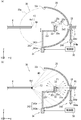
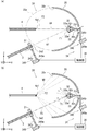
- the optical conversion device 30 As shown in FIGS. 2A and 2B, the optical conversion device 30 according to the first embodiment is, for example, a holding unit 31, a wavelength conversion unit 32, a driving unit 34, and a control unit 36. And have. Each part of the optical conversion device 30 is directly or indirectly fixed to the housing 3b of the repeater 3 via, for example, another member or the like.
- the holding portion 31 holds the first emitting end portion 2e2 as the emitting portion.
- the holding portion 31 has a first emission end portion 2e2 so that the excitation light P0 is emitted from the first emission end portion 2e2 in the ⁇ X direction. Holds.
- the optical axis A2 of the first emission end portion 2e2 is drawn by a line segment of a thin alternate long and short dash line
- the direction of travel is drawn by a two-dot chain arrow.
- the holding portion 31 has, for example, a cylindrical portion through which the first exit end portion 2e2 of the first optical transmission fiber 2 is inserted.
- the holding portion 31 may, for example, sandwich the outer peripheral portion of the first emission end portion 2e2, or may be adhered to the outer peripheral portion of the first emission end portion 2e2.
- the wavelength conversion unit 32 can emit fluorescence W0, for example, by receiving the excitation light P0 emitted from the first emission end portion 2e2 as the emission unit.
- the wavelength conversion unit 32 includes, for example, a portion (also referred to as a front portion) 32a to which the excitation light P0 emitted from the first emission end portion 2e2 as an emission portion is irradiated, and a portion (also referred to as a front portion) opposite to the front portion 32a. It has 32b (also referred to as a back portion).
- the front portion 32a is located on the + X side and the back portion 32b is located on the ⁇ X side.
- the wavelength conversion unit 32 has, for example, a flat plate shape or a film shape.
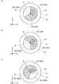
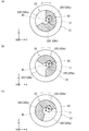
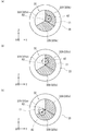
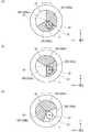
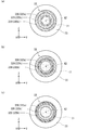
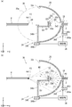
- the wavelength conversion unit 32 has a plurality of phosphor regions 320, for example, as shown in FIGS. 3 (a) to 3 (c).
- the wavelength conversion unit 32 has a configuration in which a plurality of phosphor regions 320 are arranged.
- the plurality of phosphor regions 320 include, for example, a first phosphor region 320a and a second phosphor region 320b.
- the plurality of phosphor regions 320 include a first phosphor region 320a, a second phosphor region 320b, and a third phosphor region 320c. ..
- the first phosphor region 320a can emit fluorescence having a first wavelength spectrum in response to irradiation with excitation light P0, for example.
- the second phosphor region 320b can emit fluorescence having a second wavelength spectrum different from the first wavelength spectrum, for example, in response to irradiation with excitation light P0.
- the third phosphor region 320c can emit fluorescence having a third wavelength spectrum different from the first wavelength spectrum and the second wavelength spectrum in response to irradiation with the excitation light P0, for example.
- fluorescence having different color temperatures can be applied to fluorescence having a first wavelength spectrum and fluorescence having a second wavelength spectrum.
- the fluorescence having the third wavelength spectrum for example, the fluorescence having a color temperature different from the color temperature of the fluorescence having the first wavelength spectrum and the second wavelength spectrum can be applied.
- light having a first color temperature is applied to fluorescence having a first wavelength spectrum.
- fluorescence having a second wavelength spectrum for example, light having a second color temperature is applied.
- fluorescence having a third wavelength spectrum for example, light having a third color temperature is applied.
- the first color temperature for example, 2650 Kelvin (K) is applied.
- K Kelvin
- 6500K is applied.
- 4000K is applied to the third color temperature.
- Each phosphor region 320 includes, for example, a solid member containing a phosphor (also referred to as a phosphor member).
- the phosphor member is a pellet-shaped member in which, for example, a transparent material such as resin or glass contains a large number of particles of a plurality of types of phosphors that emit fluorescence in response to irradiation with excitation light P0. (Also called phosphor pellet) is adopted.
- each phosphor region 320 can be realized by changing the abundance ratio of a large number of particles of a plurality of types of phosphors.
- the phosphor member may have a transparent substrate such as resin or glass and phosphor pellets located on the substrate.
- the plurality of phosphor regions 320 may be arranged on, for example, one substrate.
- the plurality of types of phosphors include, for example, a phosphor that emits fluorescence of the first color in response to irradiation of the excitation light P0 and fluorescence of a second color different from the first color in response to the irradiation of the excitation light P0. Includes a fluorescent substance that emits light.
- a plurality of types of phosphors are, for example, a phosphor (also referred to as a red phosphor) that emits red (R) fluorescence in response to irradiation with excitation light P0, and green in response to irradiation with excitation light P0.
- a configuration including a phosphor that emits fluorescence of (G) (also referred to as a green phosphor) and a phosphor that emits blue (B) fluorescence in response to irradiation with excitation light P0 (also referred to as a blue phosphor) can be considered. Be done.
- the plurality of types of phosphors are, for example, a phosphor (also referred to as a bluish green phosphor) that emits bluish green fluorescence (also referred to as a bluish green phosphor) in response to irradiation with excitation light P0, and a phosphor depending on irradiation with excitation light P0.
- a phosphor that emits fluorescence of various colors depending on the irradiation of the excitation light P0 such as a phosphor that emits yellow fluorescence (also referred to as a yellow phosphor), may be included.
- red phosphor for example, a phosphor having a peak of the wavelength of fluorescence emitted in response to irradiation of excitation light P0 in the range of about 620 nm to 750 nm is applied.
- the material of the red phosphor for example, CaAlSiN 3: Eu, Y 2 O 2 S: Eu, Y 2 O 3: Eu, SrCaClAlSiN 3: Eu 2+, CaAlSiN 3: Eu or CaAlSi (ON) 3: Eu, etc. Applies.
- the green phosphor for example, a phosphor having a peak wavelength of fluorescence emitted in response to irradiation of excitation light P0 in the range of about 495 nm to 570 nm is applied.
- Materials for the green phosphor include, for example, ⁇ -SiAlON: Eu, SrSi 2 (O, Cl) 2 N 2 : Eu, (Sr, Ba, Mg) 2 SiO 4 : Eu2 2+ , ZnS: Cu, Al or Zn. 2 SiO 4 : Mn or the like is applied.
- the blue phosphor for example, a phosphor having a peak wavelength of fluorescence emitted in response to irradiation of excitation light P0 in the range of about 450 nm to 495 nm is applied.
- Materials for the blue phosphor include, for example, (Ba, Sr) MgAl 10 O 17 : Eu, BaMgAl 10 O 17 : Eu, (Sr, Ca, Ba) 10 (PO 4 ) 6 C 12 : Eu or (Sr, Sr, Ba) 10 (PO 4 ) 6 C 12 : Eu etc. are applied.
- the blue-green phosphor for example, a phosphor having a peak of the wavelength of fluorescence emitted in response to irradiation of excitation light P0 in the range of about 495 nm is applied.
- the material of the blue-green phosphor for example, (Sr, Ba, Ca) 5 (PO 4 ) 3 Cl: Eu or Sr 4 Al 14 O 25 : Eu and the like are applied.
- the yellow phosphor for example, a phosphor having a peak of the wavelength of fluorescence emitted in response to irradiation of excitation light P0 in the range of about 570 nm to 590 nm is applied.
- SrSi 2 (O, Cl) 2 N 2 : Eu or the like is applied to the material of the yellow phosphor.
- the ratio of the elements in parentheses may be arbitrarily set as long as it is within the range of the molecular formula.
- the drive unit 34 can change, for example, the region (also referred to as the irradiated region) I1 to which the excitation light P0 is irradiated in the plurality of phosphor regions 320.
- the drive unit 34 moves the wavelength conversion unit 32 so that the first emission end 2e2 as an emission unit is relative to the plurality of phosphor regions 320.
- Positional relationship can be changed.
- the drive unit 34 is, for example, a mechanism for rotating the wavelength conversion unit 32 around a virtual rotation axis (also referred to as a first rotation axis) R1 different from the optical axis A2 of the excitation light P0 irradiated to the wavelength conversion unit 32.
- 341 is included (also referred to as a first rotation mechanism).
- the first rotation axis R1 is a virtual rotation axis deviated from the optical axis A2 of the excitation light P0.
- the drive unit 34 moves, for example, the heat sink 33 to which the wavelength conversion unit 32 is bonded to move the irradiated region I1 in the plurality of phosphor regions 320.
- the heat sink 33 includes, for example, a portion (also referred to as a bonded portion) 33 m to which the wavelength conversion unit 32 is joined, a rod portion 33r projecting from the bonded portion 33m in the ⁇ X direction, and the ⁇ X side of the rod portion 33r. It has a bevel gear-shaped gear portion 33 g fixed to the tip of the rod.
- the rod portion 33r is directly or other membered by the housing 3b so that it can rotate about the first rotation axis R1 along the direction along the X axis (also referred to as the X axis direction), for example. It is indirectly supported through.
- the first rotation mechanism 341 includes, for example, a motor portion 341m, a rod portion 341r, and a gear portion 341g.
- the rod portion 341r is a rod-shaped member having a longitudinal direction along a direction along the Z axis (also referred to as a Z axis direction).
- a bevel gear-shaped gear portion 341g is fixed to the tip of the rod portion 341r on the + Z side.
- the gear portion 341g meshes with the gear portion 33g.
- the motor portion 341m can rotate the rod portion 341r and the gear portion 341g around a virtual rotation shaft R34 along the Z-axis direction.
- the rotational force of the gear portion 341g is transmitted to the gear portion 33g, so that the heat sink 33 and the wavelength conversion unit 32 can rotate about the first rotation axis R1.
- the plurality of phosphor regions 320 can rotate about the first rotation axis R1.
- the heat sink 33 has a higher thermal conductivity than, for example, the wavelength conversion unit 32.
- the wavelength conversion unit 32 can be cooled from the back portion 32b side by the heat sink 33.
- the back portion 32b and the jointed portion 33m are in direct contact with each other, for example.
- the back portion 32b of the wavelength conversion portion 32 and the bonded portion 33m of the heat sink 33 can be directly bonded.
- the phosphor pellet has a structure in which a large number of particles of the phosphor are present in the low melting point glass, the phosphor particles and the material of the heat sink 33 share oxygen to form the phosphor pellet.
- the bonded portion 33m of the heat sink 33 can be bonded.
- a metal oxide having a melting point of about 400 ° C. (400 ° C.) to 500 ° C. and having a property of transmitting light (also referred to as transparency) is adopted.
- the bonded portion 33m of the heat sink 33 has a property of reflecting light
- the excitation light P0 once passed through the wavelength conversion unit 32 is reflected by the bonded portion 33m and the wavelength is converted again. Enter the section 32.
- the bonded portion 33m reflects the fluorescence W0 emitted in the wavelength conversion unit 32 toward the bonded portion 33m.
- the fluorescence W0 emitted by the wavelength conversion unit 32 can be increased.
- a metal material or the like is applied to the material of the heat sink 33.
- this metal material include copper (Cu), aluminum (Al), magnesium (Mg), gold (Au), silver (Ag), iron (Fe), chromium (Cr), cobalt (Co), and beryllium ( Be), molybdenum (Mo), tungsten (W), alloys and the like are applied.
- Cu, Al, Mg, Fe, Cr, Co or Be is adopted as the metal material, the heat sink 33 can be easily manufactured by a casting method such as die casting.
- the metal material for example, if Al, Mg, Ag, Fe, Cr or Co is adopted as the metal material, the reflectance of visible light at the bonded portion 33 m increases, and the fluorescence emitted in response to the excitation light P0 The amount of light of W0 can be increased.
- a non-metallic material such as silicon nitride (Si 3 N 4 ), carbon (C) or aluminum oxide (Al 2 O 3) may be adopted.
- the non-metallic material may be, for example, a material having crystallinity or a non-crystalline material having no crystallinity.
- silicon carbide (SiC) or Si 3 N 4 can be adopted.
- the bonded portion 33m of the heat sink 33 may have, for example, a layer of a metal material (also referred to as a high light reflecting layer) having a higher light reflectance than the main body portion of the heat sink 33.
- a metal material also referred to as a high light reflecting layer
- Cu may be applied to the material of the main body of the heat sink 33
- Ag or Cr which has a high reflectance of visible light
- a high light reflection layer can be formed on the surface of the main body of the heat sink 33 manufactured by a casting method such as die casting by vapor deposition or plating.
- a dielectric multilayer film having a structure in which a thin film of a dielectric is repeatedly laminated a plurality of times may be located on the high light reflecting layer.
- the dielectric include titanium oxide (TiO 3 ), silicon dioxide (SiO 2 ), niobium pentoxide (Nb 2 O 5 ), tantalum pentoxide (Ta 2 O 5 ), and magnesium fluoride (Mg F 2 ).
- TiO 3 titanium oxide
- SiO 2 silicon dioxide
- Ta 2 O 5 tantalum pentoxide
- Mg F 2 magnesium fluoride
- the control unit 36 changes the irradiated region I1 of the excitation light P0 in the plurality of phosphor regions 320 by driving the drive unit 34, and stops the drive of the drive unit 34 in the plurality of phosphor regions 320.
- the irradiated area I1 can be controlled to be set.
- the control unit 36 is driven by the drive unit 34 to position the first emission end 2e2 as an emission unit and the plurality of phosphor regions 320 relative to each other. You can change the relationship.
- the control unit 36 can control the amount of rotation of the wavelength conversion unit 32 centered on the first rotation axis R1 by controlling the rotation angle of the motor unit 341m of the first rotation mechanism 341, for example.
- the control unit 36 can control the timing of stopping the motor unit 341m by detecting, for example, the rotation angle of the motor unit 341m.
- a control board or a microcomputer is applied to the control unit 36.
- a large-scale integrated circuit (LSI) in which a central processing unit (CPU), a memory, and the like are integrated is applied to a microcomputer.
- the control unit 36 can control the operation of the drive unit 34 by transmitting and receiving signals to and from the drive unit 34, for example.
- the control unit 36 may control the operation of the drive unit 34 in response to a signal from an external device of the optical conversion device 30, for example.
- the wavelength conversion unit 32 has a first phosphor region 320a, a second phosphor region 320b, and a third phosphor region 320c. And, it is assumed that it is divided into. In this case, for example, when the wavelength conversion unit 32 is rotated around the first rotation axis R1, the ratio of the plurality of phosphor regions 320 in the irradiated region I1 is changed.
- the wavelength spectrum of the fluorescence W0 emitted by the wavelength conversion unit 32 is changed, and color adjustment (also referred to as toning) such as the color temperature of the light (also referred to as emitted light) emitted from the light conversion device 30 is performed.
- color adjustment also referred to as toning
- the color of the emitted light can be adjusted without adding a light emitting element. Therefore, for example, the light conversion device 30 can easily adjust the color of the emitted light.
- the first rotation axis R1 In a plan view of the wavelength conversion unit 32 in the direction along the above, it is conceivable that a plurality of phosphor regions 320 are arranged in the circumferential direction centered on the first rotation axis R1. Specifically, for example, the first phosphor region 320a, the second phosphor region 320b, and the third phosphor region 320c are arranged in this order in the circumferential direction centered on the first rotation axis R1. It is conceivable that this is the case. In this case, for example, by rotating the wavelength conversion unit 32 around the first rotation axis R1, the ratio of the plurality of phosphor regions 320 in the irradiated region I1 can be easily changed.
- the fluorescence W0 emitted from the wavelength conversion unit 32 becomes fluorescence at the second color temperature emitted from the second phosphor region 320b.
- the fluorescence W0 emitted from the wavelength conversion unit 32 is the fluorescence of the first color temperature emitted from the first phosphor region 320a. It becomes.
- the fluorescence W0 emitted from the wavelength conversion unit 32 becomes the fluorescence of the third color temperature emitted from the third phosphor region 320c.
- the irradiated region I1 is located across the second phosphor region 320b and the third phosphor region 320c.
- the fluorescence W0 emitted from the wavelength conversion unit 32 is the fluorescence of the second color temperature emitted from the second phosphor region 320b and the fluorescence of the third color temperature emitted from the third phosphor region 320c. Is a mixed fluorescence.
- the ratio of the fluorescence of the second color temperature and the fluorescence of the third color temperature being mixed is determined according to the ratio of the second phosphor region 320b and the third phosphor region 320c in the irradiated region I1.
- the irradiated region I1 is located across the first phosphor region 320a and the third phosphor region 320c. Therefore, for example, the fluorescence W0 emitted from the wavelength conversion unit 32 is a mixture of the fluorescence of the first color temperature emitted from the first phosphor region 320a and the fluorescence of the third color temperature emitted from the third phosphor region 320c. It becomes fluorescent.
- the ratio of the fluorescence of the first color temperature and the fluorescence of the third color temperature being mixed is determined according to the ratio of the first phosphor region 320a and the third phosphor region 320c in the irradiated region I1. Can be set. Further, for example, if the irradiated region I1 is located across the first phosphor region 320a and the second phosphor region 320b, the fluorescence W0 emitted from the wavelength conversion unit 32 is the first phosphor region. The fluorescence is a mixture of the fluorescence of the first color temperature emitted from 320a and the fluorescence of the second color temperature emitted from the second phosphor region 320b.
- the ratio of the fluorescence of the first color temperature and the fluorescence of the second color temperature being mixed is determined according to the ratio of the first phosphor region 320a and the second phosphor region 320b in the irradiated region I1. Can be set.
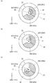
- the number of the plurality of phosphor regions 320 in the wavelength conversion unit 32 may be two or four or more.
- the wavelength conversion unit 32 may have two or more phosphor regions 320.
- the wavelength conversion unit 32 may be divided into a first phosphor region 320a and a second phosphor region 320b.
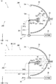
- the first phosphor region 320a and the second phosphor region 320b are arranged in this order in the circumferential direction centered on the first rotation axis R1. Further, for example, as shown in FIG.
- the wavelength conversion unit 32 includes a first phosphor region 320a, a fourth phosphor region 320d, a fifth phosphor region 320e, and a second phosphor region. It may be divided into 320b.
- the first phosphor region 320a, the fourth phosphor region 320d, the fifth phosphor region 320e, and the second phosphor region 320b are rotated in this order. They are arranged in the circumferential direction about the axis R1.
- the fourth phosphor region 320d can emit fluorescence having a fourth wavelength spectrum in response to irradiation with the excitation light P0, for example.
- the fifth phosphor region 320e can emit fluorescence having a fifth wavelength spectrum in response to irradiation with the excitation light P0, for example.
- fluorescence having a fourth wavelength spectrum for example, light having a fourth color temperature is applied.
- fluorescence having a fifth wavelength spectrum for example, light having a fifth color temperature is applied.
- the fourth color temperature for example, 3000 K is applied.
- the fifth color temperature for example, 5000K is applied.
- the wavelength conversion unit 32 has a first phosphor region 320a, a fourth phosphor region 320d, a third phosphor region 320c, and a fifth phosphor region.
- the first phosphor region 320a, the fourth phosphor region 320d, the third phosphor region 320c, the fifth phosphor region 320e, and the second phosphor region 320b are arranged in this order in the circumferential direction centered on the first rotation axis R1.
- the sizes of the plurality of phosphor regions 320 in the wavelength conversion unit 32 may be substantially the same or different.
- the phosphor region 320 which occupies a relatively large proportion of the plurality of phosphor regions 320, is appropriately matched to the color required for the illumination light I0 according to the environment in which the illumination system 100 is installed. It may be set. For example, when the illumination light I0 is required to have a warm-colored tint, the area of the phosphor region 320 that emits fluorescence in the wavelength spectrum exhibiting the warm-colored color temperature may be expanded.
- the phosphor region 320 that occupies a relatively large proportion of the plurality of phosphor regions 320 corresponds to a color that has been used for a long time or is frequently used, the same phosphor region 320
- the irradiated area I1 can be changed within. Thereby, for example, the life of the wavelength conversion unit 32 can be extended.
- the first phosphor region 320a includes a region on the first rotation axis R1 of the wavelength conversion unit 32 and is irradiated.
- a region that overlaps with region I1 may be included.
- the ratio of the excitation light P0 being irradiated to the first phosphor region 320a becomes high.
- the light conversion device 30 suitable for the case where the fluorescence having the first wavelength spectrum is frequently used is obtained.
- the first wavelength spectrum and the first color temperature of the fluorescence emitted by the first phosphor region 320a in response to the irradiation of the excitation light P0 are appropriately set according to the frequently used wavelength spectrum and the color temperature. May be done.
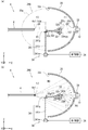
- the light conversion device 30 includes, for example, a reflection unit 35.
- the reflection unit 35 is located, for example, so as to surround the wavelength conversion unit 32, and can reflect the fluorescence W0 emitted by the wavelength conversion unit 32. Thereby, for example, the amount of light of the fluorescence W0 toward the desired direction can be increased.
- the reflection unit 35 has, for example, a concave reflection surface 35r located toward the front portion 32a of the wavelength conversion unit 32.
- the reflecting surface 35r can, for example, condense the fluorescence W0 emitted by the wavelength conversion unit 32 toward the second incident end portion 4e1.
- the amount of light of the fluorescence W0 transmitted by the second optical transmission fiber 4 can be increased.
- the wavelength conversion unit 32 is located between the reflection surface 35r and the second incident end portion 4e1.
- a bowl-shaped reflector is applied to the reflecting portion 35.
- the reflecting surface 35r is located, for example, so as to surround the wavelength conversion unit 32 from the front portion 32a side.
- the reflecting surface 35r is recessed in the direction (+ X direction) from the back portion 32b to the front portion 32a, for example.
- the virtual YZ cross section of the reflective surface 35r has, for example, a circular shape.
- the maximum value of the diameter in the virtual circular cross section of the reflecting surface 35r along the YZ plane is, for example, about 5 cm to 6 cm.
- the reflecting portion 35 has, for example, a through hole 35h located along the optical axis A2 of the first emitting end portion 2e2.
- the excitation light P0 can be irradiated from the first emission end portion 2e2 toward the wavelength conversion portion 32.
- the first exit end 2e2 may be inserted into, for example, the through hole 35h.
- the reflecting unit 35 may be, for example, an ellipsoidal mirror having a reflecting surface 35r along a virtual ellipsoidal surface (also referred to as a virtual ellipsoidal surface) 35e.
- the first focal point F1 of the virtual ellipsoidal surface 35e is located along the wavelength conversion unit 32
- the fluorescence W0 emitted from the wavelength conversion unit 32 is the first of the virtual ellipsoidal surface 35e.
- the light can be focused toward the second focal point F2, which is different from the focal point F1.
- the second focal point F2 is located along the second incident end of the second optical transmission fiber 4, the amount of light of the fluorescence W0 incident on the second optical transmission fiber 4 can be increased. ..
- the second optical transmission fiber 4 is arranged along, for example, a linear virtual line A4 passing through the first focal point F1 and the second focal point F2.
- the optical conversion device 30 for example, by driving the drive unit 34, the irradiated region I1 of the excitation light P0 in the plurality of phosphor regions 320 is changed, and the drive of the drive unit 34 is stopped.
- the drive unit 34 is controlled so as to set the irradiated region I1 in the plurality of phosphor regions 320.
- the wavelength spectrum of the fluorescence W0 emitted by the wavelength conversion unit 32 can be changed to adjust the color of the emitted light emitted from the optical conversion device 30.
- the color of the emitted light can be adjusted without adding a light emitting element. Therefore, for example, the light conversion device 30 can easily adjust the color of the emitted light.
- the drive unit 34 moves the holding unit 31 to move the holding unit 31 to the first emission end portion 2e2 as an emission unit.
- the relative positional relationship with the plurality of phosphor regions 320 may be changed.
- the drive unit 34 moves, for example, at least one of the holding unit 31 and the wavelength conversion unit 32 so that the first emission end portion 2e2 as the emission portion and the plurality of phosphor regions 320
- the relative positional relationship may be changed.
- control unit 36 changes the irradiated region I1 of the excitation light P0 in the plurality of phosphor regions 320 by driving the drive unit 34, and stops the drive of the drive unit 34. Therefore, it is possible to control so as to set the irradiated region I1 in the plurality of phosphor regions 320.
- the drive unit 34 is, for example, a virtual rotation axis (second) different from the optical axis A2.
- a mechanism (also referred to as a second rotation mechanism) 342 that rotates the holding portion 31 around R2 (also referred to as a rotation axis) is included.
- the second rotation axis R2 is a virtual rotation axis deviated from the optical axis A2.
- the second rotation mechanism 342 includes, for example, a motor portion 342m and a rod portion 342r.
- the rod portion 342r is a rod-shaped member having a longitudinal direction along the X-axis direction.
- a holding portion 31 is fixed to the tip of the rod portion 342r on the ⁇ X side.
- the motor unit 342m can rotate the rod unit 342r around the second rotation axis R2 along the X-axis direction, for example.
- the holding portion 31 and the first emitting end portion 2e2 can rotate about the second rotation axis R2.
- the heat sink 33 is held directly or indirectly by, for example, the housing 3b via another member.
- the irradiated region I1 can rotate about the second rotation axis R2 on the plurality of phosphor regions 320.
- the irradiated region I1 in the plurality of phosphor regions 320 can be changed.
- the color matching of the emitted light in the light conversion device 30 can be easily performed as in the first embodiment.
- the first phosphor region 320a includes a region on the second rotation axis R2 of the wavelength conversion unit 32. Moreover, the region that overlaps with the irradiated region I1 may be included. In this case, for example, the ratio of the excitation light P0 being irradiated to the first phosphor region 320a becomes high. As a result, for example, the light conversion device 30 suitable for the case where the fluorescence having the first wavelength spectrum is frequently used is obtained.
- the first wavelength spectrum and the first color temperature of the fluorescence emitted by the first phosphor region 320a in response to the irradiation of the excitation light P0 are appropriately set according to the frequently used wavelength spectrum and the color temperature. May be done.
- the front portion 32a is located on the ⁇ X side and the back portion 32b is located on the + X side in the wavelength conversion unit 32.
- the holding portion 31 may hold the first emitting end portion 2e2 so as to irradiate the front portion 32a with the excitation light P0 from an oblique direction.
- the driving unit 34 can change the irradiated region I1 in the plurality of phosphor regions 320, for example.
- control unit 36 changes the irradiated region I1 of the excitation light P0 in the plurality of phosphor regions 320 by driving the drive unit 34, and stops the drive of the drive unit 34, thereby causing the plurality of phosphor regions. It can be controlled to set the irradiated area I1 in 320.
- the drive unit 34 moves the wavelength conversion unit 32 to form a second output unit.
- the relative positional relationship between the emission end portion 2e2 and the plurality of phosphor regions 320 can be changed.
- the drive unit 34 includes, for example, a first rotation mechanism 341 that rotates the wavelength conversion unit 32 around a first rotation axis R1 different from the optical axis A2 of the excitation light P0 irradiated to the wavelength conversion unit 32.
- the drive unit 34 includes, for example, a first rotation mechanism 341 that rotates the wavelength conversion unit 32 around the first rotation axis R1 deviated from the optical axis A2 of the excitation light P0 irradiated to the wavelength conversion unit 32. ..
- the drive unit 34 can change the irradiated area I1 in the plurality of phosphor regions 320 by moving the heat sink 33 to which the wavelength conversion unit 32 is bonded.
- the heat sink 33 has, for example, a bonded portion 33 m to which the wavelength conversion unit 32 is bonded, and a rod portion 33r protruding from the bonded portion 33 m in the + X direction.
- the first rotation mechanism 341 includes, for example, a motor unit 341 m.
- the motor unit 341m can rotate the rod unit 33r around the first rotation shaft R1.
- the heat sink 33 and the wavelength conversion unit 32 can rotate about the first rotation axis R1.
- the plurality of phosphor regions 320 can rotate about the first rotation axis R1.
- the wavelength conversion unit 32 includes a first phosphor region 320a, a second phosphor region 320b, and a third phosphor region 320c. And, it is divided into. Therefore, for example, when the wavelength conversion unit 32 is rotated around the first rotation axis R1, the ratio of the plurality of phosphor regions 320 in the irradiated region I1 is changed. As a result, for example, the wavelength spectrum of the fluorescence W0 emitted by the wavelength conversion unit 32 is changed, and the color of the light emitted from the light conversion device 30 is adjusted.
- the color of the emitted light can be adjusted without adding a light emitting element, and the color of the emitted light can be easily adjusted in the light conversion device 30.
- the first rotation axis R1 is used.
- the wavelength conversion unit 32 is centered on the first rotation axis R1.
- the front portion 32a is located on the ⁇ X side and the back portion 32b is on the + X side.
- the holding portion 31 may hold the first emitting end portion 2e2 so as to irradiate the front portion 32a with the excitation light P0 from an oblique direction.
- the driving unit 34 can change the irradiated region I1 in the plurality of phosphor regions 320, for example.
- the drive unit 34 moves the holding unit 31 to form the first output unit.
- the relative positional relationship between the emission end portion 2e2 and the plurality of phosphor regions 320 can be changed.
- the drive unit 34 includes, for example, a second rotation mechanism 342 that rotates the holding unit 31 around a second rotation axis R2 different from the optical axis A2.
- the drive unit 34 includes, for example, a second rotation mechanism 342 that rotates the holding unit 31 around the second rotation axis R2 deviated from the optical axis A2.
- the second rotation mechanism 342 includes, for example, a motor portion 342m and a rod portion 342r.
- the rod portion 342r is a rod-shaped member having a longitudinal direction along the direction in which the optical axis A2 extends.
- a holding portion 31 is fixed to the tip of the rod portion 342r.
- the motor unit 342m can rotate the rod unit 342r around the second rotation axis R2, which is in a relationship of being offset in parallel with the optical axis A2, for example.
- the holding portion 31 and the first emitting end portion 2e2 can rotate about the second rotation axis R2.
- the irradiated region I1 can rotate about the second rotation axis R2 on the plurality of phosphor regions 320.
- the wavelength conversion unit 32 includes a first phosphor region 320a, a second phosphor region 320b, and a third phosphor region 320c. And, it is divided into. Therefore, for example, when the holding portion 31 is rotated around the second rotation axis R2, the ratio of the plurality of phosphor regions 320 in the irradiated region I1 is changed. As a result, for example, the wavelength spectrum of the fluorescence W0 emitted by the wavelength conversion unit 32 is changed, and the color of the light emitted from the light conversion device 30 is adjusted.
- the color of the emitted light can be adjusted without adding a light emitting element, and the color of the emitted light can be easily adjusted in the light conversion device 30.
- the second rotation axis R2 In the plan view of the wavelength conversion unit 32 in the direction along the line, if a plurality of phosphor regions 320 are arranged in the circumferential direction centered on the second rotation axis R2, the holding unit 31 and the holding unit 31 centering on the second rotation axis R2.
- the ratio of the plurality of phosphor regions 320 in the irradiated region I1 can be easily changed.
- the heat sink 33 may be a transparent member.
- the heat sink 33 may be a transparent member.
- the wavelength conversion unit 32 can emit fluorescence W0 from both the front portion 32a and the back portion 32b.
- the heat sink 33 for example, a transparent rod portion 33r is connected to a transparent substrate.
- the heat sink 33 has, for example, a substrate-like shape.
- a transparent material having excellent thermal conductivity (also referred to as a high thermal conductive transparent material) is applied to the heat sink 33.
- a single crystal of an inorganic oxide is applied to the material of the high thermal conductive transparent material.
- sapphire or magnesia is applied to this inorganic oxide.
- the back portion 32b of the wavelength conversion unit 32 and the high heat conductive transparent body can be brought into contact with each other. ..
- the phosphor pellet when the phosphor pellet has a structure in which a large number of particles of a plurality of types of phosphors are contained in the low melting point glass, the phosphor particles and the material of the high thermal conductive transparent material are oxygenated.
- the phosphor pellet and the highly heat conductive transparent material are bonded.
- a single crystal of glass or aluminum nitride (AlN) may be applied to the material of the heat sink 33.
- the high thermal conductive transparent body may be located on the front portion 32a of the wavelength conversion unit 32.
- the heat sink 33 may be located on the front portion 32a instead of on the back portion 32b.
- the drive unit 34 has a wavelength conversion unit 32 and a holding unit in a direction (also referred to as a first intersection direction) in which the excitation light P0 intersects the optical axis A2. It may have a mechanism (also referred to as a first movement mechanism) for relatively moving the 31.
- the control unit 36 changes the irradiated region I1 of the excitation light P0 in the plurality of phosphor regions 320 by driving the drive unit 34, and stops the drive of the drive unit 34, thereby causing a plurality of plurality.
- the irradiated region I1 in the phosphor region 320 can be controlled to be set.
- the wavelength spectrum of the fluorescence W0 emitted by the wavelength conversion unit 32 can be changed to adjust the color of the emitted light emitted from the optical conversion device 30.
- the drive unit 34 is a wavelength conversion unit in the Z-axis direction as the first intersection direction. It has a first linear motion mechanism 343 as an example of a first moving mechanism for moving 32.
- the first linear motion mechanism 343 has, for example, a rod portion 343r and a moving portion 343m.
- the rod portion 343r is connected to, for example, the rod portion 33r of the heat sink 33.
- the moving portion 343m can move the rod portion 343r in the Z-axis direction, for example.
- a mechanism having, for example, a motor and a ball screw is applied to the moving portion 343 m.
- the moving unit 343m can move the heat sink 33 and the wavelength conversion unit 32 in the Z-axis direction by moving the rod unit 343r in the Z-axis direction.
- the control unit 36 can control the movement amount and position of the wavelength conversion unit 32 in the Z-axis direction by, for example, controlling the rotation speed of the motor in the moving unit 343m.
- the control unit 36 may control the timing of stopping the motor by detecting, for example, the rotation speed of the motor in the moving unit 343 m.
- various actuators may be applied to the moving portion 343 m.
- the rod portion 343r has a form in which one end in the longitudinal direction is supported, but both ends in the longitudinal direction are supported. You may have.
- the driving unit 34 is the holding unit 31 in the Z-axis direction as the first crossing direction. It has a second linear motion mechanism 344 as a first moving mechanism for moving the light.
- the second linear motion mechanism 344 has, for example, a rod portion 344r and a moving portion 344m.
- the rod portion 344r is connected to, for example, the holding portion 31.
- the moving portion 344m can move the rod portion 344r in the Z-axis direction, for example.
- a mechanism having, for example, a motor and a ball screw is applied to the moving portion 344 m.
- the moving portion 344m can move the holding portion 31 and the first exit end portion 2e2 in the Z-axis direction by moving the rod portion 344r in the Z-axis direction.
- the control unit 36 can control the movement amount and the position of the holding unit 31 in the Z-axis direction by, for example, controlling the rotation speed of the motor in the moving unit 344m.
- the control unit 36 may control the timing of stopping the motor by detecting, for example, the rotation speed of the motor in the moving unit 344 m.
- various actuators may be applied to the moving portion 344 m. In the examples of FIGS.
- the rod portion 344r has a form in which one end in the longitudinal direction is supported, but both ends in the longitudinal direction are supported. You may have. Further, here, for example, at least one mechanism of the first linear motion mechanism 343 and the second linear motion mechanism 344 may exist.
- the wavelength conversion unit 32 has a plurality of phosphor regions 320 including a first phosphor region 320a and a second phosphor region 320b.
- the wavelength conversion unit 32 is divided into a first phosphor region 320a and a second phosphor region 320b.
- the ratio of the plurality of phosphor regions 320 in the irradiated region I1 is changed. ..
- the wavelength spectrum of the fluorescence W0 emitted by the wavelength conversion unit 32 is changed, and the color of the emitted light emitted from the optical conversion device 30 is adjusted.
- the wavelength conversion unit 32 when the wavelength conversion unit 32 is viewed in a plane in the direction along the optical axis A2 of the excitation light P0, in other words, it is along the optical axis A2 of the excitation light P0.
- a plurality of phosphor regions 320 are arranged in the Z-axis direction as the first crossing direction.
- the first phosphor region 320a and the second phosphor region 320b are arranged in this order in the ⁇ Z direction.
- the plurality of phosphor regions 320 can be reached.
- the irradiated area I1 can be moved.
- the irradiated region I1 can be easily changed in the plurality of phosphor regions 320.
- the fluorescence W0 emitted from the wavelength conversion unit 32 becomes the fluorescence of the first color temperature emitted from the first phosphor region 320a.
- the irradiated region I1 with respect to the wavelength conversion unit 32
- the irradiated region I1 is located across the first phosphor region 320a and the second phosphor region 320b.
- the fluorescence W0 emitted from the wavelength conversion unit 32 is the fluorescence of the first color temperature emitted from the first phosphor region 320a and the fluorescence of the second color temperature emitted from the second phosphor region 320b. Is a mixed fluorescence.
- the ratio of the fluorescence of the first color temperature and the fluorescence of the second color temperature being mixed is determined according to the ratio of the first phosphor region 320a and the second phosphor region 320b in the irradiated region I1.
- the irradiated region I1 is moved with respect to the wavelength conversion unit 32.
- the fluorescence W0 emitted from the wavelength conversion unit 32 becomes the fluorescence of the second color temperature emitted from the second phosphor region 320b.
- the wavelength conversion unit 32 when the wavelength conversion unit 32 is viewed in a plan view in the direction along the optical axis A2 of the excitation light P0, in other words, it is along the optical axis A2 of the excitation light P0.
- the plan view of the wavelength conversion unit 32 in the direction even if the boundary B1 between the first phosphor region 320a and the second phosphor region 320b extends so as to be inclined with respect to the Z-axis direction as the first crossing direction. good.
- the amount of change in the ratio of the ratio between the first phosphor region 320a and the second phosphor region 320b in the irradiated region I1 becomes smaller than the amount of movement of the irradiated region I1 in the plurality of phosphor regions 320. ..
- the ratio of the region where the excitation light P0 is irradiated in the first phosphor region 320a and the region where the excitation light P0 is irradiated in the second phosphor region 320b can be precisely changed. Therefore, for example, the light conversion device 30 can precisely adjust the color of the emitted light.
- the number of the plurality of phosphor regions 320 in the wavelength conversion unit 32 may be three or more.
- the wavelength conversion unit 32 may have two or more phosphor regions 320.
- the wavelength conversion unit 32 is divided into a first phosphor region 320a, a second phosphor region 320b, and a third phosphor region 320c. It may have been done.
- the first phosphor region 320a and the second phosphor region 320b are arranged in the ⁇ Z direction in this order, and the third phosphor region 320c and the third phosphor region 320c are arranged in this order.
- the two fluorophore regions 320b are arranged in this order in the ⁇ Z direction. Further, in the example of FIG. 17C, the boundary B1 between the first phosphor region 320a and the second phosphor region 320b and the boundary B2 between the third phosphor region 320c and the second phosphor region 320b are respectively. It extends so as to be inclined with respect to the Z-axis direction as the first crossing direction.
- the front portion 32a is located on the ⁇ X side and the back portion 32b is located on the + X side.
- the first exit end 2e2 may be held so that the holding portion 31 is positioned and irradiates the front portion 32a with the excitation light P0 from an oblique direction.
- the heat sink 33 is positioned so as to extend in the + X direction from the back portion 32b of the wavelength conversion unit 32, and the rod portion 33r is positioned in the + X direction. It is located so that it extends.
- the wavelength conversion unit 32 is divided into a first phosphor region 320a and a second phosphor region 320b, the wavelength conversion unit 32 and the holding unit 32 When at least one of 31 is relatively moved in the Z-axis direction as the first crossing direction, the ratio of the plurality of phosphor regions 320 in the irradiated region I1 is changed. As a result, for example, the wavelength spectrum of the fluorescence W0 emitted by the wavelength conversion unit 32 is changed, and the color of the emitted light emitted from the optical conversion device 30 is adjusted. Specifically, for example, as shown in FIG.
- the irradiated region I1 can be easily changed in the plurality of phosphor regions 320.
- FIG. 19B when the wavelength conversion unit 32 is viewed in a plan view in the direction along the optical axis A2 of the excitation light P0, in other words, it is along the optical axis A2 of the excitation light P0.
- the boundary B1 between the first phosphor region 320a and the second phosphor region 320b extends so as to be inclined with respect to the Z-axis direction as the first crossing direction. good.
- the ratio of the region where the excitation light P0 is irradiated in the first phosphor region 320a and the region where the excitation light P0 is irradiated in the second phosphor region 320b can be precisely changed.
- the color matching of the emitted light in the light conversion device 30 can be precisely performed.
- the number of the plurality of phosphor regions 320 in the wavelength conversion unit 32 may be three or more. In other words, for example, the wavelength conversion unit 32 may have two or more phosphor regions 320.
- the sizes of the plurality of phosphor regions 320 may be substantially the same or different.
- the phosphor region 320 which occupies a relatively large proportion of the plurality of phosphor regions 320, is appropriately matched to the color required for the illumination light I0 according to the environment in which the illumination system 100 is installed. It may be set. For example, when the illumination light I0 is required to have a bluish tint, the phosphor region that emits fluorescence in the wavelength spectrum exhibiting the bluish color temperature may be expanded. Further, for example, when the illumination light I0 is required to have a reddish tint, the phosphor region that emits fluorescence in a wavelength spectrum exhibiting a color temperature corresponding to the reddish tint may be expanded.
- the phosphor region 320 that occupies a relatively large proportion of the plurality of phosphor regions 320 corresponds to a color that has been used for a long time or is frequently used, the same phosphor region 320
- the irradiated area I1 can be changed within. Thereby, for example, the life of the wavelength conversion unit 32 can be extended.
- the heat sink 33 may be a transparent member.
- the wavelength conversion unit 32 can emit fluorescence W0 from both the front portion 32a and the back portion 32b.
- a transparent rod portion 33r is connected to a transparent substrate.
- a transparent body having excellent thermal conductivity high thermal conductive transparent body
- the high thermal conductive transparent body may be located on the front portion 32a of the wavelength conversion unit 32.
- the first linear motion mechanism 343 and the second linear motion mechanism 344 causes the first crossing direction.
- the wavelength conversion unit 32 and the holding unit 31 may be relatively moved in a direction in which they intersect both the optical axis A2 and the first intersection direction (also referred to as the second intersection direction).
- the first linear motion mechanism 343 may move the wavelength conversion unit 32 in the direction along the Y-axis as the second crossing direction (also referred to as the Y-axis direction), or the second linear motion mechanism 343 may move the wavelength conversion unit 32.
- the moving mechanism 344 may move the holding portion 31.
- a configuration in which the moving portion 343 m is moved by a combination of a ball screw and a motor or an actuator along a linear guide extending in the Y-axis direction can be adopted.
- a configuration in which the moving portion 344 m is moved by a combination of a ball screw and a motor or an actuator along a linear guide extending in the Y-axis direction can be adopted.
- the wavelength conversion unit 32 when the wavelength conversion unit 32 is viewed in a plane in the direction along the optical axis A2 of the excitation light P0, in other words, it is along the optical axis A2 of the excitation light P0.
- a plurality of phosphor regions 320 may be arranged in each of the Z-axis direction as the first crossing direction and the Y-axis direction as the second crossing direction.
- the control unit 36 can freely change the ratio occupied by the plurality of phosphor regions 320 in the irradiated region I1 by controlling the operation of the drive unit 34. Further, here, as shown in FIG.
- the first phosphor region 320a and the second phosphor are relative to the Z-axis direction as the first crossing direction and the Y-axis direction as the second crossing direction, respectively. It may extend so as to incline.
- the ratio occupied by each of the plurality of phosphor regions 320 in the irradiated region I1 can be precisely changed.
- the color matching of the emitted light in the light conversion device 30 can be precisely performed.
- the drive unit 34 has the holding unit 31 and the wavelength conversion unit 32 in a direction (also referred to as an optical axis direction) along the optical axis A2 of the excitation light P0. It may have a mechanism for changing the distance (also referred to as a second moving mechanism).
- the distance between the first emission end portion 2e2 as the emission portion and the wavelength conversion unit 32 is changed, the size of the irradiated region I1 can be changed.
- the irradiated region I1 of the excitation light P0 in the plurality of phosphor regions 320 can be changed.
- the control unit 36 changes the irradiated region I1 of the excitation light P0 in the plurality of phosphor regions 320 by driving the drive unit 34, for example, and stops the drive of the drive unit 34, thereby causing a plurality of plurality.
- the irradiated region I1 in the phosphor region 320 can be controlled to be set.
- the wavelength spectrum of the fluorescence W0 emitted by the wavelength conversion unit 32 can be changed to adjust the color of the emitted light emitted from the optical conversion device 30.
- the drive unit 34 holds the holding unit 31 in the X-axis direction as the optical axis direction. It has a third linear motion mechanism 345 as an example of the second moving mechanism to be moved.
- the third linear motion mechanism 345 has, for example, a rod portion 345r and a moving portion 345m.
- the rod portion 345r is connected to, for example, the holding portion 31.
- the moving portion 345m can move the rod portion 345r in the X-axis direction, for example.
- a mechanism having, for example, a motor and a ball screw is applied to the moving portion 345 m.
- the moving portion 345m can move the holding portion 31 in the X-axis direction by moving the rod portion 345r in the X-axis direction.
- the control unit 36 can control the movement amount and the position of the holding unit 31 in the X-axis direction by controlling the rotation speed of the motor in the moving unit 345m, for example.
- the control unit 36 may control the timing of stopping the motor by detecting, for example, the rotation speed of the motor in the moving unit 345 m.
- various actuators may be applied to the moving portion 345 m.
- the rod portion 345r has a form in which one end in the longitudinal direction is supported, but both ends in the longitudinal direction are supported. You may have.
- the drive unit 34 is a wavelength conversion unit 32 in the X-axis direction as the optical axis direction.
- the fourth linear motion mechanism 346 is provided as an example of the second moving mechanism for moving the light.
- the fourth linear motion mechanism 346 has, for example, a rod portion 346r and a moving portion 346m.
- the rod portion 346r is connected to, for example, the rod portion 33r of the heat sink 33.
- the moving portion 346m can move the rod portion 346r in the X-axis direction, for example.
- a mechanism having, for example, a motor and a ball screw is applied to the moving portion 346m.
- the moving unit 346m can move the heat sink 33 and the wavelength conversion unit 32 in the X-axis direction by moving the rod unit 346r in the X-axis direction.
- the control unit 36 can control the movement amount and the position of the wavelength conversion unit 32 in the X-axis direction by, for example, controlling the rotation speed of the motor in the moving unit 346m.
- the control unit 36 may control the timing of stopping the motor by detecting, for example, the rotation speed of the motor in the moving unit 346m.
- various actuators may be applied to the moving portion 346m. In the examples of FIGS.
- the rod portion 346r has a form in which one end in the longitudinal direction is supported, but both ends in the longitudinal direction are supported. You may have. Further, here, for example, at least one of the third linear motion mechanism 345 and the fourth linear motion mechanism 346 may be present.
- the wavelength conversion unit 32 includes a plurality of phosphors including a first phosphor region 320a and a second phosphor region 320b. It has a region 320.
- the wavelength conversion unit 32 includes a first phosphor region 320a, a second phosphor region 320b, and a third phosphor region 320c. And, it is assumed that it is divided into.
- the size of the irradiated region I1 is large according to the distance between the first emission end 2e2 and the wavelength conversion unit 32. Is changed. Thereby, for example, the ratio of the plurality of phosphor regions 320 in the irradiated region I1 is changed. As a result, for example, the wavelength spectrum of the fluorescence W0 emitted by the wavelength conversion unit 32 is changed, and the color of the emitted light emitted from the optical conversion device 30 is adjusted.
- the wavelength conversion unit 32 is set in the X-axis direction (specifically, the ⁇ X direction) as the optical axis direction of the excitation light P0.
- the plan view in other words, in the plan view of the wavelength conversion unit 32 in the X-axis direction (specifically, the ⁇ X direction) as the optical axis direction of the excitation light P0, a plurality of fluorescences are emitted in the direction away from the optical axis A2.
- the body regions 320 are arranged. In this case, for example, by changing the distance between the first emission end 2e2 and the wavelength conversion unit 32, as shown in FIGS.
- the irradiated area I1 The size is changed, and the ratio occupied by the plurality of phosphor regions 320 in the irradiated region I1 can be easily changed. As a result, for example, the color matching of the emitted light in the light conversion device 30 can be easily performed.
- the fluorescence W0 emitted from the wavelength conversion unit 32 becomes the fluorescence of the first color temperature emitted from the first phosphor region 320a.
- the fluorescence W0 emitted from the wavelength conversion unit 32 is the fluorescence of the first color temperature emitted from the first phosphor region 320a and the fluorescence of the third color temperature emitted from the third phosphor region 320c. Is a mixed fluorescence.
- the ratio of the fluorescence of the first color temperature and the fluorescence of the third color temperature being mixed is determined according to the ratio of the first phosphor region 320a and the third phosphor region 320c in the irradiated region I1. Can be set. Then, for example, as the distance between the first emission end 2e2 and the wavelength conversion unit 32 becomes longer, the diameter of the irradiated area I1 becomes larger, and as shown in FIG. 24C, the irradiated area becomes larger.
- the first phosphor region 320a, the third phosphor region 320c, and the second phosphor region 320b are located in I1.
- the fluorescence W0 emitted from the wavelength conversion unit 32 is the fluorescence of the first color temperature emitted from the first phosphor region 320a and the fluorescence of the third color temperature emitted from the third phosphor region 320c.
- the fluorescence of the second color temperature emitted from the second phosphor region 320b are mixed fluorescence.
- fluorescence at the first color temperature and fluorescence at the third color temperature are obtained according to the ratio of the first phosphor region 320a, the third phosphor region 320c, and the second phosphor region 320b in the irradiated region I1.
- the fluorescence of the second color temperature can be set.
- the diameter of the wavelength conversion unit 32 is set to, for example, about 0.1 mm (mm) to about 20 mm.
- the diameter of the first phosphor region 320a is set to about 0.1 mm to 10 mm.
- the diameter of the irradiated area I1 is set to, for example, about 0.1 mm to 10 mm.
- the wavelength conversion unit 32 and the plurality of phosphor regions 320 are each rectangular. It may have a shape other than a circular shape.
- the number of the plurality of phosphor regions 320 in the wavelength conversion unit 32 may be two or four or more. In other words, for example, the wavelength conversion unit 32 may have two or more phosphor regions 320.
- the first phosphor region 320a is a region including a region on the optical axis A2 of the wavelength conversion unit 32, the fluorescence having the first wavelength spectrum is frequently used. It becomes a suitable optical conversion device 30.
- the first wavelength spectrum and the first color temperature of the fluorescence emitted by the first phosphor region 320a in response to the irradiation of the excitation light P0 are appropriately set according to the frequently used wavelength spectrum and the color temperature. May be good.
- the front portion 32a of the wavelength conversion unit 32 is on the ⁇ X side.
- the first emission end portion 2e2 may be held so that the back portion 32b is located on the + X side and the holding portion 31 irradiates the excitation light P0 with respect to the front portion 32a from an oblique direction.
- the heat sink 33 is positioned so as to extend in the + X direction from the back portion 32b of the wavelength conversion unit 32, and the rod portion 33r is positioned so as to extend in the + X direction.
- the third linear motion mechanism 345 as an example of the second moving mechanism moves the holding portion 31 in the optical axis direction along the optical axis A2 inclined with respect to the virtual line A4.
- the moving portion 345m can move the holding portion 31 and the first exit end portion 2e2 in the optical axis direction by moving the rod portion 345r in the optical axis direction.
- the control unit 36 can control the movement amount and position of the holding unit 31 and the first exit end 2e2 in the optical axis direction by, for example, controlling the rotation speed of the motor in the moving unit 345m. ..
- the fourth linear motion mechanism 346 as an example of the second moving mechanism moves the wavelength conversion unit 32 in the optical axis direction along the optical axis A2 inclined with respect to the virtual line A4.
- the moving unit 346m can move the heat sink 33 and the wavelength conversion unit 32 in the optical axis direction by moving the rod unit 346r in the optical axis direction.
- the control unit 36 can control the movement amount and the position of the wavelength conversion unit 32 along the optical axis direction by controlling, for example, the rotation speed of the motor in the moving unit 346m.
- at least one of the third linear motion mechanism 345 and the fourth linear motion mechanism 346 may be present.
- the heat sink 33 is a transparent member. May be good.
- the wavelength conversion unit 32 can emit fluorescence W0 from both the front portion 32a and the back portion 32b.
- a transparent rod portion 33r is connected to a transparent substrate.
- a transparent body having excellent thermal conductivity high thermal conductive transparent body
- the high thermal conductive transparent body may be located on the front portion 32a of the wavelength conversion unit 32.
- the light radiation module 5 may include a light conversion device 30F having the same configuration as the light conversion device 30 according to any one of the first to sixth embodiments.
- the lighting system 100F includes, for example, a light emitting module 1, a first optical transmission fiber 2, and a light emitting module 5.
- the first incident end 2e1 of the first optical transmission fiber 2 is located in the light emitting module 1
- the first exit end 2e2 of the first optical transmission fiber 2 is located in the light emitting module 5.
- the first optical transmission fiber 2 can transmit the excitation light P0 from the light emitting module 1 to the optical radiation module 5.
- the optical conversion device 30F can receive the excitation light P0 emitted from the first emission end portion 2e2 of the first optical transmission fiber 2 as an emission portion and emit fluorescence W0.
- the light radiation module 5 can radiate the fluorescence W0 emitted by the light conversion device 30F into the external space 200 of the lighting system 100F as the illumination light I0.
- the optical conversion device 30F includes a holding unit 31, a wavelength conversion unit 32, a driving unit 34, and a control unit 36.
- the holding portion 31 holds the first emitting end portion 2e2 as the emitting portion.
- the wavelength conversion unit 32 is arranged with a plurality of phosphor regions 320.
- the drive unit 34 changes the irradiated region I1 in the plurality of phosphor regions 320.
- the control unit 36 changes the irradiated area I1 in the plurality of phosphor regions 320 by driving the driving unit 34, and stops the driving of the driving unit 34 to set the irradiated area I1 in the plurality of phosphor regions 320.
- the drive unit 34 is controlled so as to do so.
- the wavelength spectrum of the fluorescence W0 emitted by the wavelength conversion unit 32 can be changed to adjust the color of the emitted light emitted from the light conversion device 30, so that the light can be emitted without adding a light emitting element. It is possible to adjust the color of the light emission. Therefore, for example, the light conversion device 30 can easily adjust the color of the emitted light. Further, for example, in the lighting system 100F, in the light emission module 5, the wavelength conversion unit 32 emits fluorescence W0 by the excitation light P0 transmitted from the light emitting module 1 by the first optical transmission fiber 2.
- a part of the fluorescence W0 traveling in a direction inclined at various angles with respect to the longitudinal direction of the optical transmission fiber is less likely to cause an optical transmission loss caused by being dissipated during transmission.
- the amount of light of the fluorescence W0 emitted from the lighting system 100F may increase according to the excitation light P0.
- the first configuration example of the light radiation module 5 according to the seventh embodiment shown in FIGS. 28 (a) and 28 (b) includes a light conversion device 30F and a light radiation unit 50.
- the optical conversion device 30F has the same configuration as one configuration example of the optical conversion device 30 according to the first embodiment shown in FIGS. 2A and 2B.
- the light emitting unit 50 includes, for example, an optical transmission unit 51 and an optical system L53.
- the optical transmission unit 51 can transmit the fluorescence W0 from the second focal point F2 toward the optical system L53, for example.
- an optical fiber or a cylindrical member whose inner surface is in a mirror surface state is applied to the optical transmission unit 51.
- the optical transmission unit 51 emits, for example, one end (also referred to as a third incident end) 5e1 for receiving the incident of the fluorescence W0 and the fluorescence W0 located on the opposite side of the third incident end 5e1. It has an end portion (also referred to as a third exit end portion) 5e2 for the function.
- the optical system L53 is located, for example, along the third emission end portion 5e2 of the optical transmission unit 51.
- the optical system L53 can, for example, radiate the fluorescence W0 transmitted by the optical transmission unit 51 to the external space 200 at a desired light distribution angle.
- a lens and a diffuser plate can be applied to the optical system L53. According to such a form, for example, the portion where the fluorescence W0 is emitted from the light emission module 5 into the external space 200 as the illumination light I0 can be reduced.
- the light emitting unit 50 is not provided, and the reflecting surface 35r Is a reflective surface along the paraboloid, and the focal point F0 of the paraboloid may be located at a position along the wavelength conversion unit 32.
- the light conversion device 30F can emit parallel rays of fluorescence W0.
- the parallel light rays may be radiated to the external space 200 as the illumination light I0 as they are, or may be radiated to the external space 200 as the illumination light I0 via various optical systems such as a lens or a diffuser. ..
- the light emitting module 1 may include a light conversion device 30G located up to the radiation module 5 and having the same configuration as the light conversion device 30 according to the first to sixth embodiments.
- the lighting system 100G includes, for example, a light emitting module 1, a second optical transmission fiber 4, and a light emitting module 5.
- the second incident end 4e1 of the second optical transmission fiber 4 is located in the light emitting module 1
- the second emitting end 4e2 of the second optical transmission fiber 4 is located in the light emitting module 5.
- the second optical transmission fiber 4 can transmit the fluorescence W0 from the light emitting module 1 to the optical radiation module 5.
- the light conversion device 30G can receive the excitation light P0 emitted from the light emitting element 10 as an emitting unit and emit fluorescence W0.
- the fluorescence W0 emitted by the light conversion device 30G of the light emitting module 1 is transmitted to the light emitting module 5 via, for example, the second optical transmission fiber 4. Then, for example, the light radiation module 5 can radiate the fluorescence W0 transmitted by the second optical transmission fiber 4 as the illumination light I0 to the external space 200 of the illumination system 100G.
- the optical conversion device 30G includes a holding unit 31, a wavelength conversion unit 32, a driving unit 34, and a control unit 36.
- the holding unit 31 holds the light emitting element 10 as an emitting unit.
- the wavelength conversion unit 32 is arranged with a plurality of phosphor regions 320.
- the drive unit 34 changes the irradiated region I1 in the plurality of phosphor regions 320.
- the control unit 36 changes the irradiated area I1 in the plurality of phosphor regions 320 by driving the driving unit 34, and stops the driving of the driving unit 34 to set the irradiated area I1 in the plurality of phosphor regions 320.
- the drive unit 34 is controlled so as to do so.
- the wavelength spectrum of the fluorescence W0 emitted by the wavelength conversion unit 32 can be changed to adjust the color of the emitted light emitted from the light conversion device 30, so that the light can be emitted without adding a light emitting element. It is possible to adjust the color of the light emission. Therefore, for example, the light conversion device 30 can easily adjust the color of the emitted light. Further, for example, in the lighting system 100G, for example, the light emission module 5 does not include the wavelength conversion unit 32. Therefore, for example, the temperature of the light radiation module 5 is unlikely to rise, and the light radiation module 5 can be miniaturized.
- One configuration example of the light emitting module 1 according to the eighth embodiment shown in FIGS. 31 (a) and 31 (b) includes a light emitting element 10 and a light conversion device 30G.
- the optical conversion device 30G has the same configuration as one configuration example of the optical conversion device 30 according to the first embodiment shown in FIGS. 2A and 2B.
- the excitation light P0 is directed from the emission portion 10f of the light emitting element 10 toward the wavelength conversion portion 32. Is emitted.
- the holding unit 31 holds the light emitting element 10.
- the holding portion 31 may have various shapes, for example, and may hold the light emitting element 10 in various forms.
- fluorescence having a specific color may be applied to fluorescence having a first wavelength spectrum, fluorescence having a second wavelength spectrum, and fluorescence having a third wavelength spectrum.
- red (R) fluorescence, green (G) fluorescence, blue (B) fluorescence, and the like are applied to the fluorescence of a specific color.
- red (R) fluorescence is applied to fluorescence having a first wavelength spectrum
- green (G) fluorescence is applied to fluorescence having a second wavelength spectrum
- fluorescence having a third wavelength spectrum It is conceivable that blue (B) fluorescence is applied to the surface.
- the first phosphor region 320a has a red phosphor
- the second phosphor region 320b has a green phosphor
- the third phosphor region 320c has a blue phosphor
- the shapes of the front portion 32a and the back portion 32b may be a planar shape such as a circular shape or a polygonal shape, or may be a non-planar shape having a curved surface or unevenness. ..
- the wavelength conversion unit 32 may have a conical shape having a flat back portion 32b and a front portion 32a having vertices, or the flat back portion 32b and a hemispherical front portion 32b. It may have a hemispherical shape having a portion 32a.
- a pyramid or a cone such as a triangular pyramid or a quadrangular pyramid is applied to the pyramid shape.
- the wavelength conversion unit 32 may have a form in which a plurality of phosphor regions 320 are integrally formed, or may have the plurality of phosphor regions 320 as two or more portions. It may have a form formed by appropriately arranging a plurality of phosphor regions 320 after being prepared separately.
- the optical conversion device 30 according to the third embodiment the optical conversion device 30 according to the fourth embodiment, and the optical conversion device 30 according to the fifth embodiment.
- the reflection unit 35 may not be present.
- the color temperature or color of the fluorescence W0 emitted from the optical converters 30, 30F, and 30G is detected by a sensor, and the control unit 36 drives the drive unit 34 according to the detection result. May be controlled.
- the reflecting surface 35r is a concave surface deviated from the virtual ellipsoidal surface 35e, and the fluorescence W0 reflected by the reflecting surface 35r may be focused by using an optical system.
- the reflecting surface 35r may be a surface along a paraboloid, and the parallel light rays of fluorescence W0 reflected by the reflecting surface 35r may be condensed by a condenser lens.
- any of the X-axis direction, the Y-axis direction, and the Z-axis direction may be the vertical direction, and the other direction may be the vertical direction.
- the drive unit 34 may be configured such that the rod portions 343r and 344r have longitudinal directions along the Y-axis direction, and the rod portions 343r and 344r are swung by the moving portions 343m and 344m. good. Even if such a configuration is adopted, the drive unit 34 can relatively move the wavelength conversion unit 32 and the holding unit 31 in a direction intersecting the optical axis A2 of the excitation light P0, for example. ..
- the driving unit 34 arranges an optical system between the emitting unit and the wavelength conversion unit 32, and by moving this optical system, the excitation light P0 is irradiated in the plurality of phosphor regions 320.
- the irradiated area I1 to be irradiated may be changed.
- the optical system may include various members such as a lens, a prism, and a reflecting portion.
- the mode of moving the optical system may include translation, rotation, swing, and the like of various members.
- the change of the irradiated region I1 is the movement of the irradiated region I1 by bending the optical axis A2 of the excitation light P0, and the diameter of the irradiated region I1 by increasing or decreasing the diameter of the cross section of the luminous flux of the excitation light P0. Increases and decreases can be included.
- the holding unit 31 is not included in the optical conversion devices 30 and 30F, but is located outside the optical conversion devices 30 and 30F. May be good. Further, in one configuration example of the light emitting module 1 according to the eighth embodiment, for example, the holding unit 31 may not be included in the light conversion device 30G and may be located outside the light conversion device 30G.
- the reflection portion 35 holds the first emission end portion 2e2 as the emission portion in the through hole 35h or the like without providing the holding portion 31. You may. Further, in one configuration example of the light emitting module 1 according to the eighth embodiment, for example, the reflecting portion 35 may hold the emitting portion 10f in the through hole 35h or the like without providing the holding portion 31.
- Light emitting module 10 Light emitting element 100, 100F, 100G Lighting system 10f Exit 2 First optical transmission fiber 200 External space 2e1 First incident end 2e2 First emission end 3 Repeater 30, 30F, 30G Optical converter 31 Holding Part 32 Wavelength conversion part 320 Fluorescent body area 320a 1st Fluorescent material area 320b 2nd Fluorescent material area 320c 3rd Fluorescent material area 320d 4th Fluorescent material area 320e 5th Fluorescent material area 34 Drive unit 341 1st rotation mechanism 342 2nd Rotation mechanism 343 1st linear motion mechanism 344 2nd linear motion mechanism 345 3rd linear motion mechanism 346 4th linear motion mechanism 35 Reflector 35e Virtual elliptical surface 35r Reflective surface 36 Control unit 4 2nd optical transmission fiber 4e1 2nd incident end Part 4e2 2nd emission end 5 Light emission module A2 Optical axis B1, B2 Boundary F1 1st focus F2 2nd focus I0 Illumination light I1 Irradiated area
Landscapes
- Engineering & Computer Science (AREA)
- Microelectronics & Electronic Packaging (AREA)
- Physics & Mathematics (AREA)
- Manufacturing & Machinery (AREA)
- Power Engineering (AREA)
- Computer Hardware Design (AREA)
- General Physics & Mathematics (AREA)
- Optics & Photonics (AREA)
- General Engineering & Computer Science (AREA)
- Astronomy & Astrophysics (AREA)
- Spectroscopy & Molecular Physics (AREA)
- Led Device Packages (AREA)
- Optical Filters (AREA)
- Non-Portable Lighting Devices Or Systems Thereof (AREA)
Abstract
光変換装置は、複数の蛍光体領域が配された波長変換部と、駆動部と、制御部と、を備えている。複数の蛍光体領域は、励起光の照射に応じて第1波長スペクトルを有する蛍光を発する第1蛍光体領域と、励起光の照射に応じて第1波長スペクトルとは異なる第2波長スペクトルを有する蛍光を発する第2蛍光体領域と、を含む。駆動部は、複数の蛍光体領域において励起光が照射される被照射領域を変更させる。制御部は、駆動部の駆動によって複数の蛍光体領域における被照射領域を変更して駆動部の駆動を停止させることで複数の蛍光体領域における被照射領域を設定するように駆動部を制御する。
Description
本開示は、光変換装置および照明システムに関する。
発光素子から放出される単色の励起光を蛍光物質によって異なる波長の光に変換することで擬似的な白色光を出射する装置が知られている(例えば、特開2011-181739号公報の記載を参照)。
光変換装置および照明システムが開示される。
光変換装置の一態様は、複数の蛍光体領域が配された波長変換部と、駆動部と、制御部と、を備えている。前記複数の蛍光体領域は、励起光の照射に応じて第1波長スペクトルを有する蛍光を発する第1蛍光体領域と、前記励起光の照射に応じて前記第1波長スペクトルとは異なる第2波長スペクトルを有する蛍光を発する第2蛍光体領域と、を含む。前記駆動部は、前記複数の蛍光体領域において前記励起光が照射される被照射領域を変更させる。前記制御部は、前記駆動部の駆動によって前記複数の蛍光体領域における前記被照射領域を変更して前記駆動部の駆動を停止させることで前記複数の蛍光体領域における前記被照射領域を設定するように前記駆動部を制御する。
照明システムの一態様は、発光モジュールと、第1光伝送ファイバと、中継器と、第2光伝送ファイバと、光放射モジュールと、を備えている。前記発光モジュールは、励起光を発する。前記第1光伝送ファイバは、前記発光モジュールから前記励起光を伝送する。前記中継器は、前記一態様の光変換装置を含む。前記第2光伝送ファイバは、前記中継器から前記蛍光を伝送する。前記光放射モジュールは、前記第2光伝送ファイバが伝送した前記蛍光を外部空間に放射する。
発光素子から放出される単色の光を蛍光物質によって異なる波長の光に変換することで、擬似的な白色光を出射する装置が知られている。
ここでは、例えば、発光素子が発する励起光を、特定波長の蛍光をそれぞれ発する複数種類の蛍光物質が混合された蛍光体(混合蛍光体ともいう)に照射することで、複数種類の蛍光物質の特性および混合比に応じた色温度の光を出射する構成が考えられる。本明細書中における色温度としては、例えば、JIS Z 8725:2015で規定される色温度または相関色温度が採用され得る。
ところが、このような構成では、例えば、複数種類の蛍光物質の特性および混合比によって出射する光(出射光ともいう)の色温度が決まるため、出射光の調色を行うことができない。
そこで、第1発光素子が発する励起光に応じて第1混合蛍光体が第1の色温度の蛍光を発する第1発光部、第2発光素子が発する励起光に応じて第2混合蛍光体が第2の色温度の蛍光を発する第2発光部、および第3発光素子が発する励起光に応じて第3混合蛍光体が第3の色温度の蛍光を発する第3発光部、のうちの2つ以上の発光部における発光強度を制御することで、出射光の色温度を変化させる構成が考えられる。
しかしながら、このような構成では、例えば、色温度が異なる蛍光をそれぞれ発する蛍光体ごとに発光素子を設け、各発光素子の発光の有無および強度などをそれぞれ制御する必要がある。
このため、光変換装置については、例えば、容易に出射光の調色を行う点で改善の余地がある。
そこで、本開示の発明者は、光変換装置および光変換装置を含む照明システムについて、容易に出射光の調色を行うことができる技術を創出した。
これについて、以下、各種実施形態について図面を参照しつつ説明する。図面では同様な構成および機能を有する部分に同じ符号が付されており、下記説明では重複説明が省略される。図面は模式的に示されたものである。図2(a)から図26(b)、図28(a)から図29(b)、図31(a)および図31(b)には、右手系のXYZ座標系が付されている。このXYZ座標系では、光変換装置から蛍光W0が出射される方向が-X方向とされている。また、-X方向に垂直な一方向が+Y方向とされ、-X方向と+Y方向との両方に直交する方向が+Z方向とされている。
図2(a)から図26(b)では、中継器3の筐体3bの図示が省略され、図29(a)から図29(b)では、光放射モジュール5の筐体5bの図示が省略され、図31(a)および図31(b)では、発光モジュール1の筐体1bの図示が省略されている。図2(b)、図6(b)、図9(b)、図11(b)、図13(b)、図14(b)、図15(b)、図16(b)、図18(b)、図20(b)、図22(b)、図23(b)、図25(b)、図26(b)、図28(b)、図29(b)および図31(b)では、それぞれ、励起光P0が進む方向が2点鎖線の矢印で描かれているとともに、蛍光W0が進む方向が細い破線の矢印で描かれている。図2(a)、図6(a)、図9(a)、図11(a)、図13(a)、図14(a)、図15(a)、図16(a)、図18(a)、図20(a)、図22(a)、図23(a)、図25(a)、図26(a)、図28(a)および図31(a)では、それぞれ、後述する仮想楕円面35eの外縁が細い2点鎖線で描かれている。図3(a)から図5(c)、図7(a)から図8(c)、図10(a)から図10(c)、図12(a)から図12(c)、図17(a)から図17(c)、図19(a)から図19(c)、図21(a)、図21(b)および図24(a)から図24(c)では、それぞれ、被照射領域I1の外縁が太い2点鎖線で描かれている。
<1.第1実施形態>
<1-1.照明システム>
図1で示されるように、第1実施形態に係る照明システム100は、例えば、発光モジュール1と、第1光伝送ファイバ2と、中継器3と、第2光伝送ファイバ4と、光放射モジュール5と、を備えている。
<1-1.照明システム>
図1で示されるように、第1実施形態に係る照明システム100は、例えば、発光モジュール1と、第1光伝送ファイバ2と、中継器3と、第2光伝送ファイバ4と、光放射モジュール5と、を備えている。
発光モジュール1は、例えば、励起光P0を発することができる。発光モジュール1は、発光素子10を有する。発光素子10は、例えば、レーザーダイオード(LD)または発光ダイオード(LED)のチップなどを含む。この発光素子10が発する励起光P0には、例えば、紫色、青紫色または青色などの単色の光が適用される。第1実施形態では、発光素子10には、例えば、405ナノメートル(nm)の紫色のレーザ光を放出する窒化ガリウム(GaN)系の半導体レーザが適用される。発光モジュール1では、例えば、発光素子10が発する励起光P0を集光用の光学系などによって第1光伝送ファイバ2の一端部(第1入射端部ともいう)2e1に向けて集光する。発光モジュール1は、例えば、各種の構成を内蔵する筐体1bを有する。
第1光伝送ファイバ2は、例えば、発光モジュール1から励起光P0を伝送することができる。第1実施形態では、第1光伝送ファイバ2は、発光モジュール1から中継器3まで位置している。具体的には、第1光伝送ファイバ2の長手方向の第1入射端部2e1が発光モジュール1内に位置し、第1光伝送ファイバ2の長手方向の第1入射端部2e1とは逆の端部(第1出射端部ともいう)2e2が中継器3内に位置している。これにより、第1光伝送ファイバ2は、発光モジュール1から中継器3まで励起光P0を伝送する光伝送路を形成している。第1光伝送ファイバ2には、例えば、光ファイバが適用される。光ファイバは、例えば、コアと、このコアよりも光の屈折率が低く且つコアの周囲を被覆するように位置しているクラッドと、を有する。この場合には、例えば、第1光伝送ファイバ2は、長手方向に沿ってコア内において励起光P0を伝送することができる。第1光伝送ファイバ2の長手方向における長さは、例えば、数十センチメートル(cm)から数十メートル(m)程度に設定される。
中継器3は、例えば、光変換装置30を含む。この光変換装置30は、例えば、第1光伝送ファイバ2が伝送した励起光P0を受けて、蛍光W0を発することができる。第1実施形態では、例えば、光変換装置30は、出射部としての第1光伝送ファイバ2の第1出射端部2e2から出射された励起光P0を受ける。ここで、光変換装置30が励起光P0に応じて発する蛍光W0は、例えば、赤色(R:Red)の光、緑色(G:Green)の光および青色(B:Blue)の光を含む。これにより、例えば、光変換装置30は、単色の励起光P0を受けて擬似的な白色光としての蛍光W0を発することができる。中継器3は、例えば、各種の構成を内蔵する筐体3bを有する。筐体3bは、例えば、励起光P0の照射に応じて光変換装置30で発する熱を放射するためのフィンを有していてもよい。
第2光伝送ファイバ4は、例えば、中継器3から蛍光W0を伝送することができる。第1実施形態では、第2光伝送ファイバ4は、中継器3から光放射モジュール5まで位置している。具体的には、第2光伝送ファイバ4の長手方向の一端部(第2入射端部ともいう)4e1が中継器3内に位置し、第2光伝送ファイバ4の長手方向の第2入射端部4e1とは逆の端部(第2出射端部ともいう)4e2が光放射モジュール5内に位置している。これにより、第2光伝送ファイバ4は、中継器3から光放射モジュール5まで蛍光W0を伝送する光伝送路を形成している。第2光伝送ファイバ4には、例えば、光ファイバが適用される。光ファイバは、例えば、コアと、このコアよりも光の屈折率が低く且つコアの周囲を被覆するように位置しているクラッドと、を有する。この場合には、例えば、第2光伝送ファイバ4は、長手方向に沿ってコア内において蛍光W0を伝送することができる。第2光伝送ファイバ4の長手方向における長さは、例えば、数十cmから十m程度に設定される。
光放射モジュール5は、例えば、第2光伝送ファイバ4が伝送した蛍光W0を照明システム100の外部の空間(外部空間ともいう)200に放射することができる。光放射モジュール5は、例えば、レンズまたは拡散板などを介して外部空間200の所望のエリアに蛍光W0を照明光I0として照射する。光放射モジュール5は、例えば、各種の構成を内蔵する筐体5bを有する。
このような構成を有する照明システム100では、例えば、発光モジュール1から第1光伝送ファイバ2で伝送された励起光P0によって光変換装置30が蛍光W0を発する。これにより、例えば、蛍光W0を光伝送ファイバで伝送する距離を短くすることができる。このため、例えば、光伝送ファイバにおいて光伝送ファイバの長手方向に対して種々の角度で傾斜する方向に進む蛍光W0の一部が伝送途中で散逸して生じる光の損失(光伝送ロスともいう)を生じにくくすることができる。その結果、例えば、励起光P0に応じて照明システム100から放射される蛍光W0の光量を増加させることができる。また、ここでは、例えば、光放射モジュール5は、光変換装置30を含まない。このため、例えば、光放射モジュール5の温度上昇が生じにくく、光放射モジュール5の小型化を図ることが容易である。したがって、例えば、励起光P0に応じて照明システム100から出射される蛍光W0の光量を増加させつつ、照明システム100の外部空間200に照明光I0を放射する光放射モジュール5の小型化を図ることができる。
<1-2.光変換装置>
図2(a)および図2(b)で示されるように、第1実施形態に係る光変換装置30は、例えば、保持部31と、波長変換部32と、駆動部34と、制御部36と、を備えている。光変換装置30の各部は、例えば、中継器3の筐体3bに直接的または他の部材などを介して間接的に固定されている。
図2(a)および図2(b)で示されるように、第1実施形態に係る光変換装置30は、例えば、保持部31と、波長変換部32と、駆動部34と、制御部36と、を備えている。光変換装置30の各部は、例えば、中継器3の筐体3bに直接的または他の部材などを介して間接的に固定されている。
保持部31は、出射部としての第1出射端部2e2を保持する。図2(a)および図2(b)の構成例では、保持部31は、第1出射端部2e2から-X方向に向けて励起光P0が出射されるように、第1出射端部2e2を保持している。図2(a)では、第1出射端部2e2の光軸A2が細い1点鎖線の線分で描かれ、図2(b)では、第1出射端部2e2から出射される励起光P0の進行方向が2点鎖線の矢印で描かれている。保持部31は、例えば、第1光伝送ファイバ2の第1出射端部2e2が挿通されている筒状の部分を有する。保持部31は、例えば、第1出射端部2e2の外周部を挟持していてもよいし、第1出射端部2e2の外周部に接着されていてもよい。
波長変換部32は、例えば、出射部としての第1出射端部2e2から出射された励起光P0を受けて、蛍光W0を発することができる。波長変換部32は、例えば、出射部としての第1出射端部2e2から出射された励起光P0が照射される部分(前部ともいう)32aと、この前部32aとは逆側の部分(裏部ともいう)32bと、を有する。第1実施形態では、例えば、波長変換部32において、前部32aが+X側に位置し、裏部32bが-X側に位置している。波長変換部32は、例えば、平板状または膜状の形状を有する。
波長変換部32は、例えば、図3(a)から図3(c)で示されるように、複数の蛍光体領域320を有する。換言すれば、波長変換部32では、複数の蛍光体領域320が配された構成を有する。複数の蛍光体領域320は、例えば、第1蛍光体領域320aと、第2蛍光体領域320bと、を含む。図3(a)から図3(c)の構成例では、複数の蛍光体領域320は、第1蛍光体領域320aと、第2蛍光体領域320bと、第3蛍光体領域320cと、を含む。第1蛍光体領域320aは、例えば、励起光P0の照射に応じて、第1波長スペクトルを有する蛍光を発することができる。第2蛍光体領域320bは、例えば、励起光P0の照射に応じて、第1波長スペクトルとは異なる第2波長スペクトルを有する蛍光を発することができる。第3蛍光体領域320cは、例えば、励起光P0の照射に応じて、第1波長スペクトルおよび第2波長スペクトルとは異なる第3波長スペクトルを有する蛍光を発することができる。ここでは、第1波長スペクトルを有する蛍光および第2波長スペクトルを有する蛍光には、例えば、色温度が相互に異なる蛍光が適用され得る。また、第3波長スペクトルを有する蛍光には、例えば、第1波長スペクトルおよび第2波長スペクトルをそれぞれ有する蛍光の色温度とは異なる色温度を有する蛍光が適用され得る。具体的には、第1波長スペクトルを有する蛍光には、例えば、第1色温度を有する光が適用される。第2波長スペクトルを有する蛍光には、例えば、第2色温度を有する光が適用される。第3波長スペクトルを有する蛍光には、例えば、第3色温度を有する光が適用される。第1色温度には、例えば、2650ケルビン(K)が適用される。第2色温度には、例えば、6500Kが適用される。第3色温度には、例えば、4000Kが適用される。
各蛍光体領域320は、例えば、蛍光体を含む固形状の部材(蛍光体部材ともいう)を含む。蛍光体部材としては、例えば、樹脂もしくはガラスなどの透明な材料中に、励起光P0の照射に応じて蛍光をそれぞれ発する複数種類の蛍光体の多数の粒子が含有されている、ペレット状の部材(蛍光体ペレットともいう)が採用される。この場合には、例えば、複数種類の蛍光体の多数の粒子の存在比率を異ならせることで、各蛍光体領域320を実現することができる。ここでは、例えば、蛍光体部材は、樹脂またはガラスなどの透明な基板と、この基板上に位置している蛍光体ペレットと、を有していてもよい。この場合には、複数の蛍光体領域320は、例えば、1枚の基板上に配されていてもよい。
複数種類の蛍光体は、例えば、励起光P0の照射に応じて第1の色の蛍光を発する蛍光体と、励起光P0の照射に応じて第1の色とは異なる第2の色の蛍光を発する蛍光体と、を含む。具体的には、複数種類の蛍光体が、例えば、励起光P0の照射に応じて赤色(R)の蛍光を発する蛍光体(赤色蛍光体ともいう)と、励起光P0の照射に応じて緑色(G)の蛍光を発する蛍光体(緑色蛍光体ともいう)と、励起光P0の照射に応じて青色(B)の蛍光を発する蛍光体(青色蛍光体ともいう)と、を含む構成が考えられる。複数種類の蛍光体は、例えば、励起光P0の照射に応じて青緑色の蛍光(青緑色蛍光体ともいう)を発する蛍光体(青緑色蛍光体ともいう)および励起光P0の照射に応じて黄色の蛍光を発する蛍光体(黄色蛍光体ともいう)など、励起光P0の照射に応じて種々の色の蛍光を発する蛍光体を含んでいてもよい。
赤色蛍光体には、例えば、励起光P0の照射に応じて発する蛍光の波長のピークが620nmから750nm程度の範囲にある蛍光体が適用される。赤色蛍光体の材料には、例えば、CaAlSiN3:Eu、Y2O2S:Eu、Y2O3:Eu、SrCaClAlSiN3:Eu2+、CaAlSiN3:EuまたはCaAlSi(ON)3:Euなどが適用される。緑色蛍光体には、例えば、励起光P0の照射に応じて発する蛍光の波長のピークが495nmから570nm程度の範囲にある蛍光体が適用される。緑色蛍光体の材料には、例えば、β-SiAlON:Eu、SrSi2(O,Cl)2N2:Eu、(Sr,Ba,Mg)2SiO4:Eu22+、ZnS:Cu,AlまたはZn2SiO4:Mnなどが適用される。青色蛍光体には、例えば、励起光P0の照射に応じて発する蛍光の波長のピークが450nmから495nm程度の範囲にある蛍光体が適用される。青色蛍光体の材料には、例えば、(Ba,Sr)MgAl10O17:Eu、BaMgAl10O17:Eu、(Sr,Ca,Ba)10(PO4)6C12:Euまたは(Sr,Ba)10(PO4)6C12:Euなどが適用される。青緑色蛍光体には、例えば、励起光P0の照射に応じて発する蛍光の波長のピークが495nm程度の範囲にある蛍光体が適用される。青緑色蛍光体の材料には、例えば、(Sr,Ba,Ca)5(PO4)3Cl:EuまたはSr4Al14O25:Euなどが適用される。黄色蛍光体には、例えば、励起光P0の照射に応じて発する蛍光の波長のピークが570nmから590nm程度の範囲にある蛍光体が適用される。黄色蛍光体の材料には、例えば、SrSi2(O,Cl)2N2:Euなどが適用される。ここでは、かっこ内の元素の割合は、分子式の範囲内であれば任意に設定してもよい。
駆動部34は、例えば、複数の蛍光体領域320において励起光P0が照射される領域(被照射領域ともいう)I1を変更させることができる。図2(a)および図2(b)の構成例では、駆動部34は、波長変換部32を動かすことで、出射部としての第1出射端部2e2と複数の蛍光体領域320との相対的な位置関係を変更させることができる。駆動部34は、例えば、波長変換部32に照射される励起光P0の光軸A2と異なる仮想的な回転軸(第1回転軸ともいう)R1を中心として波長変換部32を回転させる機構(第1回転機構ともいう)341を含む。言い換えると、第1回転軸R1は、励起光P0の光軸A2からずれた仮想的な回転軸である。
図2(a)および図2(b)の構成例では、駆動部34は、例えば、波長変換部32が接合しているヒートシンク33を動かすことで、複数の蛍光体領域320における被照射領域I1を変更することができる。ヒートシンク33は、例えば、波長変換部32が接合された部分(被接合部ともいう)33mと、被接合部33mから-X方向に突出しているロッド部33rと、このロッド部33rの-X側の先端に固定された傘歯車状のギア部33gと、を有する。ロッド部33rは、例えば、X軸に沿った方向(X軸方向ともいう)に沿った第1回転軸R1を中心として回転が可能となるように、筐体3bによって直接的または他の部材を介して間接的に支持されている。第1回転機構341は、例えば、モータ部341mと、ロッド部341rと、ギア部341gと、を含む。ロッド部341rは、Z軸に沿った方向(Z軸方向ともいう)に沿った長手方向を有する棒状の部材である。ロッド部341rの+Z側の先端には、例えば、傘歯車状のギア部341gが固定されている。ギア部341gは、ギア部33gと噛合している。モータ部341mは、Z軸方向に沿った仮想的な回転軸R34を中心としてロッド部341rおよびギア部341gを回転させることができる。これにより、例えば、ギア部341gの回転力が、ギア部33gに伝達されることで、ヒートシンク33および波長変換部32が、第1回転軸R1を中心として回転し得る。その結果、例えば、図3(a)から図3(c)で示されるように、複数の蛍光体領域320が、第1回転軸R1を中心として回転し得る。
ヒートシンク33は、例えば、波長変換部32よりも高い熱伝導率を有する。これにより、例えば、ヒートシンク33によって波長変換部32を裏部32b側から冷却することができる。裏部32bと被接合部33mとは、例えば、直接接している。例えば、ヒートシンク33の被接合部33m上に蛍光体ペレットを加熱成型などで形成することで、波長変換部32の裏部32bとヒートシンク33の被接合部33mとを直接接合させることができる。例えば、蛍光体ペレットが、低融点ガラス中に蛍光体の多数の粒子が存在する構成を有する場合には、蛍光体の粒子とヒートシンク33の素材とが酸素を共有することで、蛍光体ペレットとヒートシンク33の被接合部33mとが接合され得る。低融点ガラスの素材には、例えば、摂氏400度(400℃)から500℃程度の融点を有し、光が透過する性質(透明性ともいう)を有する金属酸化物が採用される。
ここで、例えば、ヒートシンク33の被接合部33mが、光を反射する性質を有していれば、波長変換部32内を一旦通った励起光P0が被接合部33mで反射して再び波長変換部32内に入る。また、例えば、波長変換部32内で発せられて被接合部33mに向かう蛍光W0を被接合部33mが反射する。これにより、例えば、波長変換部32が発する蛍光W0が増加し得る。
ヒートシンク33の素材には、例えば、金属材料などが適用される。この金属材料には、例えば、銅(Cu)、アルミニウム(Al)、マグネシウム(Mg)、金(Au)、銀(Ag)、鉄(Fe)、クロム(Cr)、コバルト(Co)、ベリリウム(Be)、モリブデン(Mo)、タングステン(W)または合金などが適用される。ここで、例えば、金属材料として、Cu、Al、Mg、Fe、Cr、CoまたはBeが採用されれば、ダイキャスト成型などの鋳造法によって、ヒートシンク33が容易に作製され得る。ここで、例えば、金属材料として、Al、Mg、Ag、Fe、CrまたはCoが採用されれば、被接合部33mにおける可視光線の反射率が上昇し、励起光P0に応じて出射される蛍光W0の光量が増加し得る。また、ヒートシンク33の素材として、例えば、窒化珪素(Si3N4)、炭素(C)または酸化アルミニウム(Al2O3)などの非金属材料が採用されてもよい。非金属材料は、例えば、結晶性を有する材料であっても、結晶性を有さない非結晶性の材料であってもよい。結晶性を有する非金属材料としては、例えば、炭化珪素(SiC)またはSi3N4が採用され得る。
また、ヒートシンク33の被接合部33mは、例えば、ヒートシンク33の本体部よりも光の反射率が高い金属材料の層(高光反射層ともいう)を有していてもよい。例えば、ヒートシンク33の本体部の素材にCuが適用され、高光反射層の素材には、例えば、可視光線の反射率が高い、AgまたはCrなどが適用され得る。この場合には、例えば、ダイキャスト成型などの鋳造法によって作製したヒートシンク33の本体部の表面に、蒸着または鍍金(めっき)などで高光反射層を形成することができる。この高光反射層上には、誘電体の薄膜が複数回繰り返して積層された構造を有する誘電体多層膜が位置していてもよい。誘電体には、例えば、酸化チタン(TiO3)、二酸化珪素(SiO2)、五酸化ニオブ(Nb2O5)、五酸化タンタル(Ta2O5)およびフッ化マグネシウム(MgF2)のうちの1つ以上の材料が適用される。
制御部36は、例えば、駆動部34の駆動によって複数の蛍光体領域320における励起光P0の被照射領域I1を変更し、駆動部34の駆動を停止させることで、複数の蛍光体領域320における被照射領域I1を設定するように制御することができる。図2(a)および図2(b)の構成例では、制御部36は、駆動部34の駆動によって出射部としての第1出射端部2e2と複数の蛍光体領域320との相対的な位置関係を変更することができる。ここでは、制御部36は、例えば、第1回転機構341のモータ部341mの回転角度を制御することで、第1回転軸R1を中心とした波長変換部32の回転量を制御することができる。制御部36は、例えば、モータ部341mの回転角度を検出することで、モータ部341mを停止するタイミングを制御することができる。制御部36には、例えば、制御基板あるいはマイクロコンピュータなどが適用される。マイクロコンピュータには、中央演算ユニット(CPU)およびメモリなどが集積された大規模集積回路(LSI)が適用される。制御部36は、例えば、駆動部34との間で信号の送受信を行うことで、駆動部34の動作を制御することができる。制御部36は、例えば、光変換装置30の外部の装置からの信号に応じて、駆動部34の動作を制御してもよい。
ここで、例えば、図3(a)から図3(c)で示されるように、波長変換部32が、第1蛍光体領域320aと、第2蛍光体領域320bと、第3蛍光体領域320cと、に区分けされている場合を想定する。この場合には、例えば、第1回転軸R1を中心にして波長変換部32を回転させると、被照射領域I1における複数の蛍光体領域320の割合が変更される。これにより、例えば、波長変換部32が発する蛍光W0の波長スペクトルが変更され、光変換装置30から出射される光(出射光ともいう)の色温度などの色の調整(調色ともいう)が行われる。このため、例えば、発光素子を増設することなく、出射光の調色を行うことができる。したがって、例えば、光変換装置30において容易に出射光の調色を行うことができる。
ここで、例えば、図3(a)から図3(c)で示されるように、第1回転軸R1に沿った方向に波長変換部32を平面視した場合、言い換えると、第1回転軸R1に沿った方向の波長変換部32の平面視において、複数の蛍光体領域320が第1回転軸R1を中心とした周方向に配列されている態様が考えられる。具体的には、例えば、第1蛍光体領域320aと、第2蛍光体領域320bと、第3蛍光体領域320cと、がこの順に、第1回転軸R1を中心とした周方向に配列されている態様が考えられる。この場合には、例えば、第1回転軸R1を中心に波長変換部32を回転させることで、被照射領域I1における複数の蛍光体領域320の割合が容易に変更され得る。
図3(a)の例では、被照射領域I1には第2蛍光体領域320bのみが位置している。このため、例えば、波長変換部32から発せられる蛍光W0は、第2蛍光体領域320bから発せられる第2色温度の蛍光となる。ここで、例えば、被照射領域I1に第1蛍光体領域320aのみが位置していれば、波長変換部32から発せられる蛍光W0は、第1蛍光体領域320aから発せられる第1色温度の蛍光となる。例えば、被照射領域I1に第3蛍光体領域320cのみが位置していれば、波長変換部32から発せられる蛍光W0は、第3蛍光体領域320cから発せられる第3色温度の蛍光となる。また、図3(b)の例では、第2蛍光体領域320bと第3蛍光体領域320cとに跨がって被照射領域I1が位置している。この場合には、例えば、波長変換部32から発せられる蛍光W0は、第2蛍光体領域320bから発せられる第2色温度の蛍光と第3蛍光体領域320cから発せられる第3色温度の蛍光とが混合された蛍光となる。ここでは、例えば、被照射領域I1における第2蛍光体領域320bと第3蛍光体領域320cとの割合に応じて、第2色温度の蛍光と第3色温度の蛍光とが混合される割合が設定され得る。図3(c)の例では、第1蛍光体領域320aと第3蛍光体領域320cとに跨がって被照射領域I1が位置している。このため、例えば、波長変換部32から発せられる蛍光W0は、第1蛍光体領域320aから発せられる第1色温度の蛍光と第3蛍光体領域320cから発せられる第3色温度の蛍光とが混合された蛍光となる。ここでは、例えば、被照射領域I1における第1蛍光体領域320aと第3蛍光体領域320cとの割合に応じて、第1色温度の蛍光と第3色温度の蛍光とが混合される割合が設定され得る。また、例えば、第1蛍光体領域320aと第2蛍光体領域320bとに跨がって被照射領域I1が位置していれば、波長変換部32から発せられる蛍光W0は、第1蛍光体領域320aから発せられる第1色温度の蛍光と第2蛍光体領域320bから発せられる第2色温度の蛍光とが混合された蛍光となる。ここでは、例えば、被照射領域I1における第1蛍光体領域320aと第2蛍光体領域320bとの割合に応じて、第1色温度の蛍光と第2色温度の蛍光とが混合される割合が設定され得る。
ここで、例えば、波長変換部32における複数の蛍光体領域320の数は、2つであってもよいし、4つ以上であってもよい。換言すれば、例えば、波長変換部32は、2つ以上の蛍光体領域320を有していてもよい。具体的には、例えば、図4(a)で示されるように、波長変換部32が、第1蛍光体領域320aと、第2蛍光体領域320bと、に区分けされていてもよい。図4(a)の例では、例えば、第1蛍光体領域320aと、第2蛍光体領域320bと、がこの順に、第1回転軸R1を中心とした周方向に配列されている。また、例えば、図4(b)で示されるように、波長変換部32が、第1蛍光体領域320aと、第4蛍光体領域320dと、第5蛍光体領域320eと、第2蛍光体領域320bと、に区分けされていてもよい。図4(b)の例では、例えば、第1蛍光体領域320aと、第4蛍光体領域320dと、第5蛍光体領域320eと、第2蛍光体領域320bと、がこの順に、第1回転軸R1を中心とした周方向に配列されている。第4蛍光体領域320dは、例えば、励起光P0の照射に応じて、第4波長スペクトルを有する蛍光を発することができる。第5蛍光体領域320eは、例えば、励起光P0の照射に応じて、第5波長スペクトルを有する蛍光を発することができる。第4波長スペクトルを有する蛍光には、例えば、第4色温度を有する光が適用される。第5波長スペクトルを有する蛍光には、例えば、第5色温度を有する光が適用される。第4色温度には、例えば、3000Kが適用される。第5色温度には、例えば、5000Kが適用される。また、例えば、図4(c)で示されるように、波長変換部32が、第1蛍光体領域320aと、第4蛍光体領域320dと、第3蛍光体領域320cと、第5蛍光体領域320eと、第2蛍光体領域320bと、に区分けされていてもよい。図4(c)の例では、例えば、第1蛍光体領域320aと、第4蛍光体領域320dと、第3蛍光体領域320cと、第5蛍光体領域320eと、第2蛍光体領域320bと、がこの順に、第1回転軸R1を中心とした周方向に配列されている。
また、ここで、例えば、波長変換部32における複数の蛍光体領域320の大きさは、略同一であってもよいし、異なっていてもよい。ここでは、例えば、複数の蛍光体領域320のうちの相対的に大きな割合を占める蛍光体領域320は、照明システム100が設置される環境に応じて照明光I0に求められる色味に合わせて適宜設定されればよい。例えば、照明光I0に暖色系の色味が求められる場合には、暖色系の色温度を呈する波長スペクトルの蛍光を発する蛍光体領域320の面積が拡大されればよい。ここで、複数の蛍光体領域320のうちの相対的に大きな割合を占める蛍光体領域320が、使用時間が長いまたは使用頻度が高い色味に対応するものであれば、同一の蛍光体領域320内において被照射領域I1を変更することができる。これにより、例えば、波長変換部32の寿命を延ばすことができる。
また、例えば、図5(a)から図5(c)で示されるように、第1蛍光体領域320aが、波長変換部32のうちの第1回転軸R1上の領域を包含し且つ被照射領域I1と重なる領域、を含んでいてもよい。この場合には、例えば、第1蛍光体領域320aに励起光P0が照射される割合が高くなる。その結果、例えば、第1波長スペクトルを有する蛍光の使用頻度が高い場合に適した光変換装置30となる。この場合には、例えば、第1蛍光体領域320aが励起光P0の照射に応じて発する蛍光の第1波長スペクトルおよび第1色温度は、使用頻度の高い波長スペクトルおよび色温度に応じて適宜設定されてもよい。
また、第1実施形態では、光変換装置30は、例えば、反射部35を備えている。
反射部35は、例えば、波長変換部32を囲むように位置し、波長変換部32が発した蛍光W0を反射することができる。これにより、例えば、所望の方向に向かう蛍光W0の光量を増加させることができる。第1実施形態では、反射部35は、例えば、波長変換部32の前部32aに向けて位置している凹面状の反射面35rを有する。この反射面35rは、例えば、波長変換部32が発した蛍光W0を第2入射端部4e1に向けて集光させることができる。これにより、例えば、第2光伝送ファイバ4で伝送される蛍光W0の光量が増加し得る。
図2(a)および図2(b)の構成例では、反射面35rと第2入射端部4e1との間に、波長変換部32が位置している。ここで、反射部35には、例えば、椀状のリフレクタが適用される。反射面35rは、例えば、前部32a側から波長変換部32を囲むように位置している。反射面35rは、例えば、裏部32bから前部32aに向かう方向(+X方向)に凹んでいる。反射面35rの仮想的なYZ断面は、例えば、円形状の形状を有する。反射面35rのYZ平面に沿った仮想的な円形状の断面における直径の最大値は、例えば、5cmから6cm程度とされる。また、反射部35は、例えば、第1出射端部2e2の光軸A2に沿うように位置している貫通孔35hを有する。これにより、例えば、第1出射端部2e2から波長変換部32に向けて励起光P0を照射することができる。第1出射端部2e2は、例えば、貫通孔35hに挿入されていてもよい。
ここで、反射部35は、例えば、仮想的な楕円面(仮想楕円面ともいう)35eに沿った反射面35rを有する楕円ミラーとされてもよい。この場合には、例えば、仮想楕円面35eの第1焦点F1が、波長変換部32に沿った箇所に位置していれば、波長変換部32から発せられる蛍光W0を仮想楕円面35eの第1焦点F1とは異なる第2焦点F2に向けて集光することができる。ここで、例えば、第2焦点F2が、第2光伝送ファイバ4の第2入射端部に沿って位置していれば、第2光伝送ファイバ4に入射される蛍光W0の光量が増加し得る。中継器3においては、第2光伝送ファイバ4は、例えば、第1焦点F1と第2焦点F2とを通る直線状の仮想線A4に沿って配置されている。
<1-3.第1実施形態のまとめ>
第1実施形態に係る光変換装置30では、例えば、駆動部34の駆動によって複数の蛍光体領域320における励起光P0の被照射領域I1を変更し、駆動部34の駆動を停止させることで、複数の蛍光体領域320における被照射領域I1を設定するように、駆動部34を制御する。これにより、例えば、波長変換部32が発する蛍光W0の波長スペクトルを変更して、光変換装置30から出射される出射光の調色を行うことができる。その結果、例えば、発光素子を増設することなく、出射光の調色を行うことができる。したがって、例えば、光変換装置30において容易に出射光の調色を行うことができる。
第1実施形態に係る光変換装置30では、例えば、駆動部34の駆動によって複数の蛍光体領域320における励起光P0の被照射領域I1を変更し、駆動部34の駆動を停止させることで、複数の蛍光体領域320における被照射領域I1を設定するように、駆動部34を制御する。これにより、例えば、波長変換部32が発する蛍光W0の波長スペクトルを変更して、光変換装置30から出射される出射光の調色を行うことができる。その結果、例えば、発光素子を増設することなく、出射光の調色を行うことができる。したがって、例えば、光変換装置30において容易に出射光の調色を行うことができる。
<2.他の実施形態>
本開示は上述の第1実施形態に限定されるものではなく、本開示の要旨を逸脱しない範囲において種々の変更および改良などが可能である。
本開示は上述の第1実施形態に限定されるものではなく、本開示の要旨を逸脱しない範囲において種々の変更および改良などが可能である。
<2-1.第2実施形態>
上記第1実施形態において、例えば、図6(a)および図6(b)で示されるように、駆動部34は、保持部31を動かすことで、出射部としての第1出射端部2e2と複数の蛍光体領域320との相対的な位置関係を変更させてもよい。換言すれば、駆動部34は、例えば、保持部31および波長変換部32のうちの少なくとも一方の部分を動かすことで、出射部としての第1出射端部2e2と複数の蛍光体領域320との相対的な位置関係を変更してもよい。このような構成が採用されても、制御部36は、例えば、駆動部34の駆動によって複数の蛍光体領域320における励起光P0の被照射領域I1を変更し、駆動部34の駆動を停止させることで、複数の蛍光体領域320における被照射領域I1を設定するように制御することができる。
上記第1実施形態において、例えば、図6(a)および図6(b)で示されるように、駆動部34は、保持部31を動かすことで、出射部としての第1出射端部2e2と複数の蛍光体領域320との相対的な位置関係を変更させてもよい。換言すれば、駆動部34は、例えば、保持部31および波長変換部32のうちの少なくとも一方の部分を動かすことで、出射部としての第1出射端部2e2と複数の蛍光体領域320との相対的な位置関係を変更してもよい。このような構成が採用されても、制御部36は、例えば、駆動部34の駆動によって複数の蛍光体領域320における励起光P0の被照射領域I1を変更し、駆動部34の駆動を停止させることで、複数の蛍光体領域320における被照射領域I1を設定するように制御することができる。
図6(a)および図6(b)で示される第2実施形態に係る光変換装置30の一構成例では、駆動部34は、例えば、光軸A2と異なる仮想的な回転軸(第2回転軸ともいう)R2を中心として保持部31を回転させる機構(第2回転機構ともいう)342を含む。言い換えると、第2回転軸R2は、光軸A2からずれた仮想的な回転軸である。第2回転機構342は、例えば、モータ部342mと、ロッド部342rと、を含む。ロッド部342rは、X軸方向に沿った長手方向を有する棒状の部材である。ロッド部342rの-X側の先端には、例えば、保持部31が固定されている。モータ部342mは、例えば、X軸方向に沿った第2回転軸R2を中心としてロッド部342rを回転させることができる。これにより、例えば、保持部31および第1出射端部2e2が、第2回転軸R2を中心として回転し得る。そして、ヒートシンク33は、例えば、筐体3bによって直接的または他の部材を介して間接的に保持されている。その結果、例えば、図7(a)から図7(c)で示されるように、被照射領域I1が、複数の蛍光体領域320上において、第2回転軸R2を中心として回転し得る。その結果、例えば、複数の蛍光体領域320における被照射領域I1が変更され得る。この場合にも、上記第1実施形態と同様に、例えば、光変換装置30における出射光の調色を容易に行うことができる。
ここで、例えば、図7(a)から図7(c)で示されるように、第2回転軸R2に沿った方向に波長変換部32を平面視した場合、言い換えると第2回転軸R2に沿った方向の波長変換部32の平面視において、複数の蛍光体領域320が第2回転軸R2を中心とした周方向に配列されている態様が考えられる。具体的には、例えば、第1蛍光体領域320aと、第2蛍光体領域320bと、第3蛍光体領域320cと、がこの順に、第2回転軸R2を中心とした周方向に配列されている態様が考えられる。この場合には、例えば、第2回転軸R2を中心に保持部31および第1出射端部2e2を回転させることで、被照射領域I1における複数の蛍光体領域320の割合が容易に変更され得る。
また、ここで、例えば、図8(a)から図8(c)で示されるように、第1蛍光体領域320aが、波長変換部32のうちの第2回転軸R2上の領域を包含し且つ被照射領域I1と重なる領域、を含んでいてもよい。この場合には、例えば、第1蛍光体領域320aに励起光P0が照射される割合が高くなる。その結果、例えば、第1波長スペクトルを有する蛍光の使用頻度が高い場合に適した光変換装置30となる。この場合には、例えば、第1蛍光体領域320aが励起光P0の照射に応じて発する蛍光の第1波長スペクトルおよび第1色温度は、使用頻度の高い波長スペクトルおよび色温度に応じて適宜設定されてもよい。
<2-2.第3実施形態>
上記第1実施形態において、例えば、図9(a)および図9(b)で示されるように、波長変換部32において前部32aが-X側に位置し且つ裏部32bが+X側に位置し、保持部31が、前部32aに対して斜め方向から励起光P0を照射するように第1出射端部2e2を保持していてもよい。この場合にも、駆動部34は、例えば、複数の蛍光体領域320において被照射領域I1を変更させることができる。そして、制御部36は、例えば、駆動部34の駆動によって複数の蛍光体領域320における励起光P0の被照射領域I1を変更し、駆動部34の駆動を停止させることで、複数の蛍光体領域320における被照射領域I1を設定するように制御することができる。
上記第1実施形態において、例えば、図9(a)および図9(b)で示されるように、波長変換部32において前部32aが-X側に位置し且つ裏部32bが+X側に位置し、保持部31が、前部32aに対して斜め方向から励起光P0を照射するように第1出射端部2e2を保持していてもよい。この場合にも、駆動部34は、例えば、複数の蛍光体領域320において被照射領域I1を変更させることができる。そして、制御部36は、例えば、駆動部34の駆動によって複数の蛍光体領域320における励起光P0の被照射領域I1を変更し、駆動部34の駆動を停止させることで、複数の蛍光体領域320における被照射領域I1を設定するように制御することができる。
図9(a)および図9(b)で示される第3実施形態に係る光変換装置30の第1構成例でも、駆動部34は、波長変換部32を動かすことで、出射部としての第1出射端部2e2と複数の蛍光体領域320との相対的な位置関係を変更させることができる。駆動部34は、例えば、波長変換部32に照射される励起光P0の光軸A2と異なる第1回転軸R1を中心として波長変換部32を回転させる第1回転機構341を含む。言い換えれば、駆動部34は、例えば、波長変換部32に照射される励起光P0の光軸A2からずれた第1回転軸R1を中心として波長変換部32を回転させる第1回転機構341を含む。
ここでは、例えば、駆動部34は、波長変換部32が接合しているヒートシンク33を動かすことで、複数の蛍光体領域320における被照射領域I1を変更することができる。ヒートシンク33は、例えば、波長変換部32が接合された被接合部33mと、被接合部33mから+X方向に突出しているロッド部33rと、を有する。第1回転機構341は、例えば、モータ部341mを含む。モータ部341mは、第1回転軸R1を中心としてロッド部33rを回転させることができる。これにより、例えば、ヒートシンク33および波長変換部32が、第1回転軸R1を中心として回転し得る。その結果、例えば、図10(a)から図10(c)で示されるように、複数の蛍光体領域320が、第1回転軸R1を中心として回転し得る。
ここでは、例えば、図10(a)から図10(c)で示されるように、波長変換部32が、第1蛍光体領域320aと、第2蛍光体領域320bと、第3蛍光体領域320cと、に区分けされている。このため、例えば、第1回転軸R1を中心にして波長変換部32を回転させると、被照射領域I1における複数の蛍光体領域320の割合が変更される。これにより、例えば、波長変換部32が発する蛍光W0の波長スペクトルが変更され、光変換装置30からの出射光の調色が行われる。このため、例えば、発光素子を増設することなく、出射光の調色を行うことができ、光変換装置30において容易に出射光の調色を行うことができる。また、例えば、図10(a)から図10(c)で示されるように、第1回転軸R1に沿った方向に波長変換部32を平面視した場合に、言い換えると第1回転軸R1に沿った方向の波長変換部32の平面視において、複数の蛍光体領域320が第1回転軸R1を中心とした周方向に配列されていれば、第1回転軸R1を中心に波長変換部32を回転させることで、被照射領域I1における複数の蛍光体領域320の割合が容易に変更され得る。
また、上記第2実施形態において、例えば、図11(a)および図11(b)で示されるように、波長変換部32において前部32aが-X側に位置し且つ裏部32bが+X側に位置し、保持部31が、前部32aに対して斜め方向から励起光P0を照射するように第1出射端部2e2を保持していてもよい。この場合にも、駆動部34は、例えば、複数の蛍光体領域320において被照射領域I1を変更させることができる。図11(a)および図11(b)で示される第3実施形態に係る光変換装置30の第2構成例でも、駆動部34は、保持部31を動かすことで、出射部としての第1出射端部2e2と複数の蛍光体領域320との相対的な位置関係を変更させることができる。駆動部34は、例えば、光軸A2と異なる第2回転軸R2を中心として保持部31を回転させる第2回転機構342を含む。言い換えると、駆動部34は、例えば、光軸A2からずれた第2回転軸R2を中心として保持部31を回転させる第2回転機構342を含む。
第2回転機構342は、例えば、モータ部342mと、ロッド部342rと、を含む。ロッド部342rは、光軸A2が延びる方向に沿った長手方向を有する棒状の部材である。ロッド部342rの先端には、例えば、保持部31が固定されている。モータ部342mは、例えば、光軸A2に対して平行にずれた関係にある第2回転軸R2を中心としてロッド部342rを回転させることができる。これにより、例えば、保持部31および第1出射端部2e2が、第2回転軸R2を中心として回転し得る。その結果、例えば、図12(a)から図12(c)で示されるように、被照射領域I1が、複数の蛍光体領域320上において、第2回転軸R2を中心として回転し得る。
ここでは、例えば、図12(a)から図12(c)で示されるように、波長変換部32が、第1蛍光体領域320aと、第2蛍光体領域320bと、第3蛍光体領域320cと、に区分けされている。このため、例えば、第2回転軸R2を中心にして保持部31を回転させると、被照射領域I1における複数の蛍光体領域320の割合が変更される。これにより、例えば、波長変換部32が発する蛍光W0の波長スペクトルが変更され、光変換装置30からの出射光の調色が行われる。このため、例えば、発光素子を増設することなく、出射光の調色を行うことができ、光変換装置30において容易に出射光の調色を行うことができる。また、例えば、図12(a)から図12(c)で示されるように、第2回転軸R2に沿った方向に波長変換部32を平面視した場合に、言い換えると第2回転軸R2に沿った方向の波長変換部32の平面視において、複数の蛍光体領域320が第2回転軸R2を中心とした周方向に配列されていれば、第2回転軸R2を中心に保持部31および第1出射端部2e2を回転させることで、被照射領域I1における複数の蛍光体領域320の割合が容易に変更され得る。
<2-3.第4実施形態>
上記第1実施形態において、例えば、図13(a)および図13(b)で示されるように、ヒートシンク33が、透明性を有する部材であってもよい。また、上記第2実施形態において、例えば、図14(a)および図14(b)で示されるように、ヒートシンク33が、透明性を有する部材であってもよい。この場合には、例えば、波長変換部32は、前部32aおよび裏部32bの双方から蛍光W0を発することができる。
上記第1実施形態において、例えば、図13(a)および図13(b)で示されるように、ヒートシンク33が、透明性を有する部材であってもよい。また、上記第2実施形態において、例えば、図14(a)および図14(b)で示されるように、ヒートシンク33が、透明性を有する部材であってもよい。この場合には、例えば、波長変換部32は、前部32aおよび裏部32bの双方から蛍光W0を発することができる。
図13(a)および図13(b)で示される第4実施形態に係る光変換装置30の第1構成例では、ヒートシンク33は、例えば、透明な基板に透明なロッド部33rが連結している形態を有する。また、図14(a)および図14(b)で示される第4実施形態に係る光変換装置30の第2構成例では、ヒートシンク33は、例えば、基板状の形状を有する。
ヒートシンク33には、例えば、熱伝導性に優れた透明体(高熱伝導透明体ともいう)が適用される。高熱伝導透明体の素材には、例えば、無機酸化物の単結晶が適用される。この無機酸化物には、例えば、サファイアまたはマグネシアなどが適用される。ここでは、例えば、高熱伝導透明体の基板上において蛍光体ペレットを加熱成型などで形成することで、波長変換部32の裏部32bと高熱伝導透明体とが接している状態とすることができる。ここで、例えば、蛍光体ペレットが、低融点ガラス中に複数種類の蛍光体の多数の粒子が含有されている構成を有する場合には、蛍光体の粒子と高熱伝導透明体の素材とが酸素を共有することで、蛍光体ペレットと高熱伝導透明体とが接合されている態様となり得る。ヒートシンク33の素材には、例えば、ガラスまたは窒化アルミニウム(AlN)の単結晶などが適用されてもよい。
また、例えば、波長変換部32の前部32a上に高熱伝導透明体が位置していてもよい。図14(a)および図14(b)の構成例では、例えば、ヒートシンク33は、裏部32b上でなく、前部32a上に位置していてもよい。
<2-4.第5実施形態>
上記第1実施形態から上記第4実施形態において、例えば、駆動部34は、励起光P0の光軸A2に対して交差する方向(第1交差方向ともいう)において、波長変換部32と保持部31とを相対的に移動させる機構(第1移動機構ともいう)を有していてもよい。この場合にも、制御部36は、例えば、駆動部34の駆動によって複数の蛍光体領域320における励起光P0の被照射領域I1を変更し、駆動部34の駆動を停止させることで、複数の蛍光体領域320における被照射領域I1を設定するように制御することができる。その結果、例えば、波長変換部32が発する蛍光W0の波長スペクトルを変更して、光変換装置30から出射される出射光の調色を行うことができる。
上記第1実施形態から上記第4実施形態において、例えば、駆動部34は、励起光P0の光軸A2に対して交差する方向(第1交差方向ともいう)において、波長変換部32と保持部31とを相対的に移動させる機構(第1移動機構ともいう)を有していてもよい。この場合にも、制御部36は、例えば、駆動部34の駆動によって複数の蛍光体領域320における励起光P0の被照射領域I1を変更し、駆動部34の駆動を停止させることで、複数の蛍光体領域320における被照射領域I1を設定するように制御することができる。その結果、例えば、波長変換部32が発する蛍光W0の波長スペクトルを変更して、光変換装置30から出射される出射光の調色を行うことができる。
図15(a)および図15(b)で示される第5実施形態に係る光変換装置30の第1構成例では、駆動部34は、第1交差方向としてのZ軸方向において、波長変換部32を移動させる第1移動機構の一例としての第1直動機構343を有する。第1直動機構343は、例えば、ロッド部343rおよび移動部343mを有する。ロッド部343rは、例えば、ヒートシンク33のロッド部33rに連結されている。移動部343mは、例えば、ロッド部343rをZ軸方向に移動させることができる。移動部343mには、例えば、モータと、ボールねじと、を有する機構が適用される。ここでは、例えば、移動部343mが、ロッド部343rをZ軸方向に移動させることで、ヒートシンク33および波長変換部32をZ軸方向に移動させることができる。ここで、制御部36は、例えば、移動部343mにおけるモータの回転数を制御することで、Z軸方向における波長変換部32の移動量および位置を制御することができる。制御部36は、例えば、移動部343mにおけるモータの回転数を検出することで、モータを停止させるタイミングを制御してもよい。また、移動部343mには、例えば、各種のアクチュエータが適用されてもよい。図15(a)および図15(b)の例では、ロッド部343rが、長手方向の一方の端部が支持された形態を有しているが、長手方向の両端部が支持された形態を有していてもよい。
図16(a)および図16(b)で示される第5実施形態に係る光変換装置30の第2構成例では、駆動部34は、第1交差方向としてのZ軸方向において、保持部31を移動させる第1移動機構としての第2直動機構344を有する。第2直動機構344は、例えば、ロッド部344rおよび移動部344mを有する。ロッド部344rは、例えば、保持部31に連結されている。移動部344mは、例えば、ロッド部344rをZ軸方向に移動させることができる。移動部344mには、例えば、モータと、ボールねじと、を有する機構が適用される。ここでは、例えば、移動部344mが、ロッド部344rをZ軸方向に移動させることで、保持部31および第1出射端部2e2をZ軸方向に移動させることができる。ここで、制御部36は、例えば、移動部344mにおけるモータの回転数を制御することで、Z軸方向における保持部31の移動量および位置を制御することができる。制御部36は、例えば、移動部344mにおけるモータの回転数を検出することで、モータを停止させるタイミングを制御してもよい。また、移動部344mには、例えば、各種のアクチュエータが適用されてもよい。図16(a)および図16(b)の例では、ロッド部344rが、長手方向の一方の端部が支持された形態を有しているが、長手方向の両端部が支持された形態を有していてもよい。また、ここでは、例えば、第1直動機構343および第2直動機構344の少なくとも一方の機構が存在していてもよい。
ここでは、例えば、図17(a)で示されるように、波長変換部32が、第1蛍光体領域320aと、第2蛍光体領域320bと、を含む複数の蛍光体領域320を有する。ここで、例えば、図17(a)で示されるように、波長変換部32が、第1蛍光体領域320aと、第2蛍光体領域320bと、に区分けされている場合を想定する。この場合には、例えば、波長変換部32および保持部31の少なくとも一方を第1交差方向としてのZ軸方向に移動させると、被照射領域I1における複数の蛍光体領域320の割合が変更される。これにより、例えば、波長変換部32が発する蛍光W0の波長スペクトルが変更され、光変換装置30から出射される出射光の調色が行われる。
ここで、例えば、図17(a)で示されるように、励起光P0の光軸A2に沿った方向に波長変換部32を平面視した場合、言い換えると励起光P0の光軸A2に沿った方向の波長変換部32の平面視において、第1交差方向としてのZ軸方向において、複数の蛍光体領域320が配列されている態様が考えられる。図17(a)の例では、第1蛍光体領域320aと、第2蛍光体領域320bと、がこの順に、-Z方向に配列されている。このような場合には、例えば、波長変換部32および保持部31のうちの少なくとも一方を第1交差方向としてのZ軸方向に沿って相対的に移動させることで、複数の蛍光体領域320に対して被照射領域I1を移動させることができる。これにより、例えば、複数の蛍光体領域320において被照射領域I1が容易に変更され得る。図17(a)の例では、被照射領域I1には第1蛍光体領域320aのみが位置している。このため、例えば、波長変換部32から発せられる蛍光W0は、第1蛍光体領域320aから発せられる第1色温度の蛍光となる。ここで、例えば、波長変換部32および保持部31のうちの少なくとも一方を第1交差方向としてのZ軸方向に沿って相対的に移動させることで、波長変換部32に対して被照射領域I1を相対的に-Z方向に移動させると、第1蛍光体領域320aと第2蛍光体領域320bとに跨がって被照射領域I1が位置している状態となる。この場合には、例えば、波長変換部32から発せられる蛍光W0は、第1蛍光体領域320aから発せられる第1色温度の蛍光と第2蛍光体領域320bから発せられる第2色温度の蛍光とが混合された蛍光となる。ここでは、例えば、被照射領域I1における第1蛍光体領域320aと第2蛍光体領域320bとの割合に応じて、第1色温度の蛍光と第2色温度の蛍光とが混合される割合が設定され得る。そして、例えば、波長変換部32および保持部31のうちの少なくとも一方を第1交差方向としてのZ軸方向に沿って相対的に移動させることで、波長変換部32に対して被照射領域I1を相対的に-Z方向に移動させると、被照射領域I1に第2蛍光体領域320bのみが位置している状態となる。この場合には、例えば、波長変換部32から発せられる蛍光W0は、第2蛍光体領域320bから発せられる第2色温度の蛍光となる。
ここで、例えば、図17(b)で示されるように、励起光P0の光軸A2に沿った方向に波長変換部32を平面視した場合、言い換えると励起光P0の光軸A2に沿った方向の波長変換部32の平面視において、第1蛍光体領域320aと第2蛍光体領域320bとの境界B1が、第1交差方向としてのZ軸方向に対して傾斜するように延びていてもよい。これにより、例えば、複数の蛍光体領域320における被照射領域I1の移動量に対して、被照射領域I1における第1蛍光体領域320aと第2蛍光体領域320bとの割合の変化量が小さくなる。その結果、例えば、第1蛍光体領域320aにおいて励起光P0が照射される領域と、第2蛍光体領域320bにおいて励起光P0が照射される領域と、の割合を精密に変更することができる。したがって、例えば、光変換装置30において出射光の調色を精密に行うことができる。
ここで、例えば、波長変換部32における複数の蛍光体領域320の数は、3つ以上であってもよい。換言すれば、例えば、波長変換部32は、2つ以上の蛍光体領域320を有していてもよい。具体的には、例えば、図17(c)で示されるように、波長変換部32が、第1蛍光体領域320aと、第2蛍光体領域320bと、第3蛍光体領域320cと、に区分けされていてもよい。図17(c)の例では、例えば、第1蛍光体領域320aと、第2蛍光体領域320bと、がこの順に、-Z方向に配列されているとともに、第3蛍光体領域320cと、第2蛍光体領域320bと、がこの順に、-Z方向に配列されている。また、図17(c)の例では、第1蛍光体領域320aと第2蛍光体領域320bとの境界B1および第3蛍光体領域320cと第2蛍光体領域320bとの境界B2のそれぞれが、第1交差方向としてのZ軸方向に対して傾斜するように延びている。
また、第5実施形態において、例えば、図18(a)および図18(b)で示されるように、波長変換部32において前部32aが-X側に位置し且つ裏部32bが+X側に位置し、保持部31が、前部32aに対して斜め方向から励起光P0を照射するように第1出射端部2e2を保持していてもよい。この第5実施形態に係る光変換装置30の第3構成例では、例えば、ヒートシンク33が、波長変換部32の裏部32bから+X方向に延びるように位置し、ロッド部33rが、+X方向に延びるように位置している。
ここで、例えば、図19(a)で示されるように、波長変換部32が、第1蛍光体領域320aと第2蛍光体領域320bとに区分けされていれば、波長変換部32および保持部31の少なくとも一方を第1交差方向としてのZ軸方向に相対的に移動させると、被照射領域I1における複数の蛍光体領域320の割合が変更される。これにより、例えば、波長変換部32が発する蛍光W0の波長スペクトルが変更され、光変換装置30から出射される出射光の調色が行われる。具体的には、例えば、図19(a)で示されるように、励起光P0の光軸A2に沿った方向に波長変換部32を平面視した場合、言い換えると励起光P0の光軸A2に沿った方向の波長変換部32の平面視において、第1交差方向としてのZ軸方向において、複数の蛍光体領域320が配列されている態様が考えられる。図19(a)の例では、第1蛍光体領域320aと第2蛍光体領域320bとがこの順に-Z方向に配列されている。ここでは、例えば、波長変換部32または保持部31を第1交差方向としてのZ軸方向に移動させることで、複数の蛍光体領域320において被照射領域I1が容易に変更され得る。ここで、例えば、図19(b)で示されるように、励起光P0の光軸A2に沿った方向に波長変換部32を平面視した場合、言い換えると励起光P0の光軸A2に沿った方向の波長変換部32の平面視において、第1蛍光体領域320aと第2蛍光体領域320bとの境界B1が、第1交差方向としてのZ軸方向に対して傾斜するように延びていてもよい。この場合には、例えば、第1蛍光体領域320aにおいて励起光P0が照射される領域と、第2蛍光体領域320bにおいて励起光P0が照射される領域と、の割合を精密に変更することができる。その結果、例えば、光変換装置30における出射光の調色が精密に行われ得る。ここで、例えば、図19(c)で示されるように、波長変換部32における複数の蛍光体領域320の数は、3つ以上であってもよい。換言すれば、例えば、波長変換部32は、2つ以上の蛍光体領域320を有していてもよい。
ここでも、複数の蛍光体領域320の大きさは、略同一であっても、異なっていてもよい。ここでは、例えば、複数の蛍光体領域320のうちの相対的に大きな割合を占める蛍光体領域320は、照明システム100が設置される環境に応じて照明光I0に求められる色味に合わせて適宜設定されればよい。例えば、照明光I0に青色っぽい色味が求められる場合には、青色っぽい色温度を呈する波長スペクトルの蛍光を発する蛍光体領域が拡大されればよい。また、例えば、照明光I0に赤みを帯びた色味が求められる場合には、赤みを帯びた色味に応じた色温度を呈する波長スペクトルの蛍光を発する蛍光体領域が拡大されればよい。ここで、複数の蛍光体領域320のうちの相対的に大きな割合を占める蛍光体領域320が、使用時間が長いまたは使用頻度が高い色味に対応するものであれば、同一の蛍光体領域320内において被照射領域I1を変更することができる。これにより、例えば、波長変換部32の寿命を延ばすことができる。
また、第5実施形態において、例えば、図20(a)および図20(b)で示されるように、ヒートシンク33が、透明性を有する部材であってもよい。この場合には、例えば、波長変換部32は、前部32aおよび裏部32bの双方から蛍光W0を発することができる。図20(a)および図20(b)で示される第5実施形態に係る光変換装置30の第4構成例では、ヒートシンク33は、例えば、透明な基板に透明なロッド部33rが連結している形態を有する。ヒートシンク33には、例えば、熱伝導性に優れた透明体(高熱伝導透明体)が適用される。また、例えば、波長変換部32の前部32a上に高熱伝導透明体が位置していてもよい。
また、例えば、上述した第5実施形態に係る光変換装置30の第2構成例から第4構成例では、第1直動機構343および第2直動機構344の少なくとも一方によって、第1交差方向だけでなく光軸A2および第1交差方向の双方に交差する方向(第2交差方向ともいう)において、波長変換部32と保持部31とを相対的に移動させてもよい。この場合には、例えば、第2交差方向としてのY軸に沿った方向(Y軸方向ともいう)において、第1直動機構343が波長変換部32を移動させてもよいし、第2直動機構344が保持部31を移動させてもよい。ここでは、例えば、第1直動機構343では、Y軸方向に延びるリニアガイドに沿ってボールねじとモータとの組み合わせあるいはアクチュエータによって移動部343mを移動させる構成が採用され得る。また、例えば、第2直動機構344では、Y軸方向に延びるリニアガイドに沿ってボールねじとモータとの組み合わせあるいはアクチュエータによって移動部344mを移動させる構成が採用され得る。
ここで、例えば、図21(a)で示されるように、励起光P0の光軸A2に沿った方向に波長変換部32を平面視した場合、言い換えると励起光P0の光軸A2に沿った方向の波長変換部32の平面視において、第1交差方向としてのZ軸方向および第2交差方向としてのY軸方向のそれぞれにおいて、複数の蛍光体領域320が配列されていてもよい。これにより、例えば、制御部36は、駆動部34の動作を制御することで、被照射領域I1において複数の蛍光体領域320がそれぞれ占める割合を自在に変更することができる。また、ここでは、図21(b)で示されるように、励起光P0の光軸A2に沿った方向に波長変換部32を平面視した場合に、第1蛍光体領域320aと第2蛍光体領域320bとの境界B1および第2蛍光体領域320bと第3蛍光体領域320cとの境界B2が、それぞれ第1交差方向としてのZ軸方向および第2交差方向としてのY軸方向のそれぞれに対して傾斜するように延びていてもよい。これにより、例えば、被照射領域I1における複数の蛍光体領域320がそれぞれ占める割合を精密に変更することができる。その結果、例えば、光変換装置30における出射光の調色が精密に行われ得る。
<2-5.第6実施形態>
上記第1実施形態から上記第5実施形態において、例えば、駆動部34は、励起光P0の光軸A2に沿った方向(光軸方向ともいう)において、保持部31と波長変換部32との距離を変更させる機構(第2移動機構ともいう)を有していてもよい。この場合には、例えば、出射部としての第1出射端部2e2と波長変換部32との距離が変更されるため、被照射領域I1の大きさを変更することができる。これにより、例えば、複数の蛍光体領域320における励起光P0の被照射領域I1を変更させることができる。そして、ここでも、制御部36は、例えば、駆動部34の駆動によって複数の蛍光体領域320における励起光P0の被照射領域I1を変更し、駆動部34の駆動を停止させることで、複数の蛍光体領域320における被照射領域I1を設定するように制御することができる。その結果、例えば、波長変換部32が発する蛍光W0の波長スペクトルを変更して、光変換装置30から出射される出射光の調色を行うことができる。
上記第1実施形態から上記第5実施形態において、例えば、駆動部34は、励起光P0の光軸A2に沿った方向(光軸方向ともいう)において、保持部31と波長変換部32との距離を変更させる機構(第2移動機構ともいう)を有していてもよい。この場合には、例えば、出射部としての第1出射端部2e2と波長変換部32との距離が変更されるため、被照射領域I1の大きさを変更することができる。これにより、例えば、複数の蛍光体領域320における励起光P0の被照射領域I1を変更させることができる。そして、ここでも、制御部36は、例えば、駆動部34の駆動によって複数の蛍光体領域320における励起光P0の被照射領域I1を変更し、駆動部34の駆動を停止させることで、複数の蛍光体領域320における被照射領域I1を設定するように制御することができる。その結果、例えば、波長変換部32が発する蛍光W0の波長スペクトルを変更して、光変換装置30から出射される出射光の調色を行うことができる。
図22(a)および図22(b)で示される第6実施形態に係る光変換装置30の第1構成例では、駆動部34は、光軸方向としてのX軸方向において、保持部31を移動させる第2移動機構の一例としての第3直動機構345を有する。第3直動機構345は、例えば、ロッド部345rおよび移動部345mを有する。ロッド部345rは、例えば、保持部31に連結されている。移動部345mは、例えば、ロッド部345rをX軸方向に移動させることができる。移動部345mには、例えば、モータと、ボールねじと、を有する機構が適用される。ここでは、例えば、移動部345mが、ロッド部345rをX軸方向に移動させることで、保持部31をX軸方向に移動させることができる。ここで、制御部36は、例えば、移動部345mにおけるモータの回転数を制御することで、X軸方向における保持部31の移動量および位置を制御することができる。制御部36は、例えば、移動部345mにおけるモータの回転数を検出することで、モータを停止させるタイミングを制御してもよい。また、移動部345mには、例えば、各種のアクチュエータが適用されてもよい。図22(a)および図22(b)の例では、ロッド部345rが、長手方向の一方の端部が支持された形態を有しているが、長手方向の両端部が支持された形態を有していてもよい。
図23(a)および図23(b)で示される第6実施形態に係る光変換装置30の第2構成例では、駆動部34は、光軸方向としてのX軸方向において、波長変換部32を移動させる第2移動機構の一例としての第4直動機構346を有する。第4直動機構346は、例えば、ロッド部346rおよび移動部346mを有する。ロッド部346rは、例えば、ヒートシンク33のロッド部33rに連結されている。移動部346mは、例えば、ロッド部346rをX軸方向に移動させることができる。移動部346mには、例えば、モータと、ボールねじと、を有する機構が適用される。ここでは、例えば、移動部346mが、ロッド部346rをX軸方向に移動させることで、ヒートシンク33および波長変換部32をX軸方向に移動させることができる。ここで、制御部36は、例えば、移動部346mにおけるモータの回転数を制御することで、X軸方向における波長変換部32の移動量および位置を制御することができる。制御部36は、例えば、移動部346mにおけるモータの回転数を検出することで、モータを停止させるタイミングを制御してもよい。また、移動部346mには、例えば、各種のアクチュエータが適用されてもよい。図23(a)および図23(b)の例では、ロッド部346rが、長手方向の一方の端部が支持された形態を有しているが、長手方向の両端部が支持された形態を有していてもよい。また、ここでは、例えば、第3直動機構345および第4直動機構346の少なくとも一方の機構が存在していてもよい。
ここでは、例えば、図24(a)から図24(c)で示されるように、波長変換部32が、第1蛍光体領域320aと、第2蛍光体領域320bと、を含む複数の蛍光体領域320を有する。ここで、例えば、図24(a)から図24(c)で示されるように、波長変換部32が、第1蛍光体領域320aと、第2蛍光体領域320bと、第3蛍光体領域320cと、に区分けされている場合を想定する。この場合には、例えば、波長変換部32および保持部31の少なくとも一方をX軸方向に移動させると、第1出射端部2e2と波長変換部32との距離に応じて被照射領域I1の大きさが変更される。これにより、例えば、被照射領域I1における複数の蛍光体領域320の割合が変更される。その結果、例えば、波長変換部32が発する蛍光W0の波長スペクトルが変更され、光変換装置30から出射される出射光の調色が行われる。
ここでは、例えば、図24(a)から図24(c)で示されるように、励起光P0の光軸方向としてのX軸方向(具体的には、-X方向)に波長変換部32を平面視した場合、言い換えると励起光P0の光軸方向としてのX軸方向(具体的には、-X方向)の波長変換部32の平面視において、光軸A2から離れる方向において、複数の蛍光体領域320が配列されている態様が考えられる。この場合には、例えば、第1出射端部2e2と波長変換部32との距離が変更されることで、図24(a)から図24(c)で示されるように、被照射領域I1の大きさが変更され、被照射領域I1において複数の蛍光体領域320が占める割合が容易に変更され得る。その結果、例えば、光変換装置30における出射光の調色を容易に行うことができる。図24(a)の例では、被照射領域I1には、第1蛍光体領域320aのみが位置している。このため、例えば、波長変換部32から発せられる蛍光W0は、第1蛍光体領域320aから発せられる第1色温度の蛍光となる。ここで、例えば、第1出射端部2e2と波長変換部32との距離が長くなることで、被照射領域I1の径が大きくなり、図24(b)で示されるように、被照射領域I1には、第1蛍光体領域320aと第3蛍光体領域320cとが位置している状態となる。この場合には、例えば、波長変換部32から発せられる蛍光W0は、第1蛍光体領域320aから発せられる第1色温度の蛍光と第3蛍光体領域320cから発せられる第3色温度の蛍光とが混合された蛍光となる。ここでは、例えば、被照射領域I1における第1蛍光体領域320aと第3蛍光体領域320cとの割合に応じて、第1色温度の蛍光と第3色温度の蛍光とが混合される割合が設定され得る。そして、例えば、第1出射端部2e2と波長変換部32との距離がさらに長くなることで、被照射領域I1の径がさらに大きくなり、図24(c)で示されるように、被照射領域I1には、第1蛍光体領域320aと、第3蛍光体領域320cと、第2蛍光体領域320bとが位置している状態となる。この場合には、例えば、波長変換部32から発せられる蛍光W0は、第1蛍光体領域320aから発せられる第1色温度の蛍光と、第3蛍光体領域320cから発せられる第3色温度の蛍光と、第2蛍光体領域320bから発せられる第2色温度の蛍光と、が混合された蛍光となる。ここでは、例えば、被照射領域I1における第1蛍光体領域320aと第3蛍光体領域320cと第2蛍光体領域320bとの割合に応じて、第1色温度の蛍光と第3色温度の蛍光と第2色温度の蛍光とが混合される割合が設定され得る。
ここで、波長変換部32の径は、例えば、0.1ミリメート(mm)から20mm程度に設定される。また、第1蛍光体領域320aの径は、0.1mmから10mm程度に設定される。また、被照射領域I1の径は、例えば、0.1mmから10mm程度に設定される。また、例えば、光軸A2に沿った光軸方向に平面視した場合、言い換えると光軸A2に沿った光軸方向の平面視において、波長変換部32および複数の蛍光体領域320は、それぞれ四角形など円形以外の形状を有していてもよい。また、例えば、波長変換部32における複数の蛍光体領域320の数は、2つであってもよいし、4つ以上であってもよい。換言すれば、例えば、波長変換部32は、2つ以上の蛍光体領域320を有していてもよい。
また、ここで、例えば、第1蛍光体領域320aが、波長変換部32のうちの光軸A2上の領域を包含する領域であれば、第1波長スペクトルを有する蛍光の使用頻度が高い場合に適した光変換装置30となる。この場合には、第1蛍光体領域320aが励起光P0の照射に応じて発する蛍光の第1波長スペクトルおよび第1色温度は、使用頻度の高い波長スペクトルおよび色温度に応じて適宜設定されてもよい。
また、第6実施形態に係る光変換装置30の第2構成例において、例えば、図25(a)および図25(b)で示されるように、波長変換部32において前部32aが-X側に位置し且つ裏部32bが+X側に位置し、保持部31が、前部32aに対して斜め方向から励起光P0を照射するように第1出射端部2e2を保持していてもよい。この場合には、例えば、ヒートシンク33が、波長変換部32の裏部32bから+X方向に延びるように位置し、ロッド部33rが、+X方向に延びるように位置している。
ここでは、例えば、第2移動機構の一例としての第3直動機構345は、仮想線A4に対して傾斜した光軸A2に沿った光軸方向において、保持部31を移動させる。具体的には、例えば、移動部345mが、ロッド部345rを光軸方向に移動させることで、保持部31および第1出射端部2e2を光軸方向に移動させることができる。ここで、制御部36は、例えば、移動部345mにおけるモータの回転数などを制御することで、光軸方向における保持部31および第1出射端部2e2の移動量および位置を制御することができる。また、例えば、第2移動機構の一例としての第4直動機構346は、仮想線A4に対して傾斜した光軸A2に沿った光軸方向において、波長変換部32を移動させる。具体的には、例えば、移動部346mが、ロッド部346rを光軸方向に移動させることで、ヒートシンク33および波長変換部32を光軸方向に移動させることができる。ここで、制御部36は、例えば、移動部346mにおけるモータの回転数などを制御することで、光軸方向に沿った波長変換部32の移動量および位置を制御することができる。また、ここでは、例えば、第3直動機構345および第4直動機構346の少なくとも一方の機構が存在していてもよい。
また、第6実施形態に係る光変換装置30の第2構成例において、例えば、図26(a)および図26(b)で示されるように、ヒートシンク33が、透明性を有する部材であってもよい。この場合には、例えば、波長変換部32は、前部32aおよび裏部32bの双方から蛍光W0を発することができる。図26(a)および図26(b)で示される第6実施形態に係る光変換装置30の第4構成例では、ヒートシンク33は、例えば、透明な基板に透明なロッド部33rが連結している形態を有する。ヒートシンク33には、例えば、熱伝導性に優れた透明体(高熱伝導透明体)が適用される。また、例えば、波長変換部32の前部32a上に高熱伝導透明体が位置していてもよい。
<2-6.第7実施形態>
上記各実施形態において、例えば、図27で示されるように、中継器3および第2光伝送ファイバ4が存在せず、第1光伝送ファイバ2が発光モジュール1から光放射モジュール5まで位置しており、光放射モジュール5が、上記第1実施形態から上記第6実施形態の何れかに係る光変換装置30と同様な構成を有する光変換装置30Fを含んでいてもよい。
上記各実施形態において、例えば、図27で示されるように、中継器3および第2光伝送ファイバ4が存在せず、第1光伝送ファイバ2が発光モジュール1から光放射モジュール5まで位置しており、光放射モジュール5が、上記第1実施形態から上記第6実施形態の何れかに係る光変換装置30と同様な構成を有する光変換装置30Fを含んでいてもよい。
図27で示されるように、第7実施形態に係る照明システム100Fは、例えば、発光モジュール1と、第1光伝送ファイバ2と、光放射モジュール5と、を備えている。ここでは、例えば、第1光伝送ファイバ2の第1入射端部2e1が発光モジュール1内に位置し、第1光伝送ファイバ2の第1出射端部2e2が光放射モジュール5内に位置している。これにより、例えば、第1光伝送ファイバ2は、発光モジュール1から光放射モジュール5まで励起光P0を伝送することができる。光放射モジュール5では、例えば、光変換装置30Fは、出射部としての第1光伝送ファイバ2の第1出射端部2e2から出射された励起光P0を受けて、蛍光W0を発することができる。そして、光放射モジュール5は、例えば、光変換装置30Fが発した蛍光W0を照明光I0として照明システム100Fの外部空間200に放射することができる。
このような構成が採用されても、例えば、光変換装置30Fは、保持部31と、波長変換部32と、駆動部34と、制御部36と、を備えている。保持部31は、出射部としての第1出射端部2e2を保持する。波長変換部32は、複数の蛍光体領域320が配されている。駆動部34は、複数の蛍光体領域320における被照射領域I1を変更させる。制御部36は、駆動部34の駆動によって複数の蛍光体領域320における被照射領域I1を変更し、駆動部34の駆動を停止させることで、複数の蛍光体領域320における被照射領域I1を設定するように駆動部34を制御する。これにより、例えば、波長変換部32が発する蛍光W0の波長スペクトルを変更して、光変換装置30から出射される出射光の調色を行うことができるため、発光素子を増設することなく、出射光の調色を行うことができる。したがって、例えば、光変換装置30において容易に出射光の調色を行うことができる。また、例えば、照明システム100Fでは、光放射モジュール5において、発光モジュール1から第1光伝送ファイバ2で伝送された励起光P0によって波長変換部32が蛍光W0を発する。これにより、例えば、光伝送ファイバにおいて光伝送ファイバの長手方向に対して種々の角度で傾斜する方向に進む蛍光W0の一部が伝送途中で散逸して生じる光伝送ロスが生じにくい。その結果、例えば、励起光P0に応じて照明システム100Fから放射される蛍光W0の光量が増加し得る。
図28(a)および図28(b)で示される第7実施形態に係る光放射モジュール5の第1構成例は、光変換装置30Fと、光放射部50と、を有する。ここでは、例えば、光変換装置30Fは、図2(a)および図2(b)で示された上記第1実施形態に係る光変換装置30の一構成例と同様な構成を有する。光放射部50は、例えば、光伝送部51と、光学系L53と、を有する。光伝送部51は、例えば、第2焦点F2から光学系L53に向けて、蛍光W0を伝送することができる。光伝送部51には、例えば、光ファイバまたは内面が鏡面状態にある円筒形の部材などが適用される。この光伝送部51は、例えば、蛍光W0の入射を受け付けるための一端部(第3入射端部ともいう)5e1と、第3入射端部5e1とは逆側に位置している蛍光W0を出射するための端部(第3出射端部ともいう)5e2と、を有する。図28(a)および図28(b)の例では、光学系L53は、例えば、光伝送部51の第3出射端部5e2に沿って位置している。光学系L53は、例えば、光伝送部51によって伝送された蛍光W0を、所望の配光角度で外部空間200に対して放射することができる。光学系L53には、例えば、レンズおよび拡散板などが適用され得る。このような形態によれば、例えば、光放射モジュール5から外部空間200に蛍光W0を照明光I0として放射する部分を小さくすることができる。
また、第7実施形態に係る光放射モジュール5の第1構成例において、例えば、図29(a)および図29(b)で示されるように、光放射部50を有さず、反射面35rが放物面に沿った反射面とされ、放物面の焦点F0が波長変換部32に沿った箇所に位置している形態とされてもよい。この場合には、例えば、図29(b)で示されるように、光変換装置30Fは、蛍光W0の平行光線を出射することができる。この平行光線は、例えば、そのまま外部空間200に照明光I0として放射されてもよいし、レンズまたは拡散板などの各種の光学系を介して、外部空間200に照明光I0として放射されてもよい。
<2-7.第8実施形態>
上記第1実施形態から上記第6実施形態において、例えば、図30で示されるように、中継器3および第1光伝送ファイバ2が存在せず、第2光伝送ファイバ4が発光モジュール1から光放射モジュール5まで位置し、発光モジュール1が、上記第1実施形態から上記第6実施形態に係る光変換装置30と同様な構成を有する光変換装置30Gを含んでいてもよい。
上記第1実施形態から上記第6実施形態において、例えば、図30で示されるように、中継器3および第1光伝送ファイバ2が存在せず、第2光伝送ファイバ4が発光モジュール1から光放射モジュール5まで位置し、発光モジュール1が、上記第1実施形態から上記第6実施形態に係る光変換装置30と同様な構成を有する光変換装置30Gを含んでいてもよい。
図30で示されるように、第8実施形態に係る照明システム100Gは、例えば、発光モジュール1と、第2光伝送ファイバ4と、光放射モジュール5と、を備えている。ここでは、例えば、第2光伝送ファイバ4の第2入射端部4e1が発光モジュール1内に位置し、第2光伝送ファイバ4の第2出射端部4e2が光放射モジュール5内に位置している。これにより、例えば、第2光伝送ファイバ4は、発光モジュール1から光放射モジュール5まで蛍光W0を伝送することができる。発光モジュール1では、例えば、光変換装置30Gは、出射部としての発光素子10から出射された励起光P0を受けて、蛍光W0を発することができる。発光モジュール1の光変換装置30Gが発した蛍光W0は、例えば、第2光伝送ファイバ4を介して光放射モジュール5に伝送される。そして、例えば、光放射モジュール5は、第2光伝送ファイバ4が伝送した蛍光W0を照明光I0として照明システム100Gの外部空間200に放射することができる。
このような構成が採用されても、例えば、光変換装置30Gは、保持部31と、波長変換部32と、駆動部34と、制御部36と、を備えている。保持部31は、出射部としての発光素子10を保持する。波長変換部32は、複数の蛍光体領域320が配されている。駆動部34は、複数の蛍光体領域320における被照射領域I1を変更させる。制御部36は、駆動部34の駆動によって複数の蛍光体領域320における被照射領域I1を変更し、駆動部34の駆動を停止させることで、複数の蛍光体領域320における被照射領域I1を設定するように駆動部34を制御する。これにより、例えば、波長変換部32が発する蛍光W0の波長スペクトルを変更して、光変換装置30から出射される出射光の調色を行うことができるため、発光素子を増設することなく、出射光の調色を行うことができる。したがって、例えば、光変換装置30において容易に出射光の調色を行うことができる。また、例えば、照明システム100Gでは、例えば、光放射モジュール5は、波長変換部32を含まない。このため、例えば、光放射モジュール5の温度上昇が生じにくく、光放射モジュール5の小型化を図ることができる。
図31(a)および図31(b)で示される第8実施形態に係る発光モジュール1の一構成例は、発光素子10と、光変換装置30Gと、を有する。ここでは、例えば、光変換装置30Gは、図2(a)および図2(b)で示された上記第1実施形態に係る光変換装置30の一構成例と同様な構成を有する。図31(a)および図31(b)の例では、第1光伝送ファイバ2の第1出射端部2e2の代わりに、発光素子10の出射部10fから波長変換部32に向けて励起光P0が出射される。そして、保持部31が、発光素子10を保持している。保持部31は、例えば、種々の形状を有し、種々の形態で発光素子10を保持していてもよい。
<3.その他>
上記各実施形態では、例えば、第1波長スペクトルを有する蛍光、第2波長スペクトルを有する蛍光および第3波長スペクトルを有する蛍光には、それぞれ特定の色の蛍光が適用されてもよい。特定の色の蛍光には、例えば、赤色(R)の蛍光、緑色(G)の蛍光および青色(B)の蛍光などが適用される。この場合には、例えば、第1波長スペクトルを有する蛍光に赤色(R)の蛍光が適用され、第2波長スペクトルを有する蛍光に緑色(G)の蛍光が適用され、第3波長スペクトルを有する蛍光に青色(B)の蛍光が適用される態様が考えられる。ここでは、例えば、第1蛍光体領域320aが赤色蛍光体を有し、第2蛍光体領域320bが緑色蛍光体を有し、第3蛍光体領域320cが青色蛍光体を有する態様が考えられる。
上記各実施形態では、例えば、第1波長スペクトルを有する蛍光、第2波長スペクトルを有する蛍光および第3波長スペクトルを有する蛍光には、それぞれ特定の色の蛍光が適用されてもよい。特定の色の蛍光には、例えば、赤色(R)の蛍光、緑色(G)の蛍光および青色(B)の蛍光などが適用される。この場合には、例えば、第1波長スペクトルを有する蛍光に赤色(R)の蛍光が適用され、第2波長スペクトルを有する蛍光に緑色(G)の蛍光が適用され、第3波長スペクトルを有する蛍光に青色(B)の蛍光が適用される態様が考えられる。ここでは、例えば、第1蛍光体領域320aが赤色蛍光体を有し、第2蛍光体領域320bが緑色蛍光体を有し、第3蛍光体領域320cが青色蛍光体を有する態様が考えられる。
上記各実施形態では、例えば、前部32aおよび裏部32bの各形状は、円形状または多角形状などの平面状であってもよいし、曲面または凹凸を有する平面状でない形状であってもよい。例えば、波長変換部32は、平面状の裏部32bと頂点を持つ前部32aとを有する錐体状の形状を有していてもよいし、平面状の裏部32bと半球面状の前部32aとを有する半球状の形状を有していてもよい。錐体状の形状には、例えば、三角錐または四角錐などの角錐体あるいは円錐などが適用される。
上記各実施形態では、例えば、波長変換部32は、複数の蛍光体領域320が一体的に形成された形態を有していてもよいし、複数の蛍光体領域320を2つ以上の部分として別々に作製した後に複数の蛍光体領域320を適宜配して形成された形態を有していてもよい。
上記第3実施形態に係る光変換装置30、第4実施形態に係る光変換装置30、上記第5実施形態に係る光変換装置30の第3構成例および第4構成例ならびに第6実施形態に係る光変換装置30の第3構成例および第4構成例では、例えば、反射部35が存在していなくてもよい。
上記各実施形態では、例えば、光変換装置30,30F,30Gから出射される蛍光W0の色温度または色をセンサーで検出し、この検出結果に応じて、制御部36が、駆動部34の駆動を制御してもよい。
上記各実施形態では、例えば、反射面35rは、仮想楕円面35eからずれた凹面状の面とされ、反射面35rで反射された蛍光W0が光学系を用いて集光されてもよい。例えば、反射面35rが放物面に沿った面とされ、反射面35rで反射された蛍光W0の平行光線が、集光レンズによって集光されてもよい。
上記各実施形態では、例えば、X軸方向、Y軸方向およびZ軸方向の何れが上下方向であってもよいし、他の方向が上下方向であってもよい。
上記第5実施形態では、例えば、駆動部34が、ロッド部343r,344rがY軸方向に沿った長手方向を有し、移動部343m,344mによってロッド部343r,344rを揺動させる構成としてもよい。このような構成が採用されても、駆動部34は、例えば、励起光P0の光軸A2に対して交差する方向において、波長変換部32と保持部31とを相対的に移動させることができる。
上記各実施形態では、例えば、駆動部34は、出射部から波長変換部32までの間に光学系を配し、この光学系を動かすことで、複数の蛍光体領域320において励起光P0が照射される被照射領域I1を変更させてもよい。ここでは、光学系には、例えば、レンズ、プリズムおよび反射部など各種部材が含まれ得る。光学系を動かす態様には、各種部材の並進、回転および揺動などが含まれ得る。そして、例えば、被照射領域I1の変更は、励起光P0の光軸A2を曲げることによる被照射領域I1の移動、および励起光P0の光束の断面の径の増減による被照射領域I1の径の増減などが含まれ得る。
上記第1実施形態、上記第4実施形態に係る光変換装置30の第1構成例、上記第5実施形態に係る光変換装置30の第1構成例、ならびに上記第7実施形態に係る光放射モジュール5の第1構成例および第2構成例の何れかにおいて、例えば、保持部31は、光変換装置30,30Fに含まれておらず、光変換装置30,30Fの外部に位置していてもよい。また、上記第8実施形態に係る発光モジュール1の一構成例において、例えば、保持部31は、光変換装置30Gに含まれておらず、光変換装置30Gの外部に位置していてもよい。
上記第1実施形態、上記第4実施形態に係る光変換装置30の第1構成例、上記第5実施形態に係る光変換装置30の第1構成例、ならびに上記第7実施形態に係る光放射モジュール5の第1構成例および第2構成例の何れかにおいて、例えば、保持部31を設けることなく、反射部35が、貫通孔35hなどにおいて、出射部としての第1出射端部2e2を保持してもよい。また、上記第8実施形態に係る発光モジュール1の一構成例において、例えば、保持部31を設けることなく、反射部35が、貫通孔35hなどにおいて、出射部10fを保持してもよい。
上記各実施形態および各種変形例をそれぞれ構成する全部または一部を、適宜、矛盾しない範囲で組み合わせ可能であることは、言うまでもない。
1 発光モジュール
10 発光素子
100,100F,100G 照明システム
10f 出射部
2 第1光伝送ファイバ
200 外部空間
2e1 第1入射端部
2e2 第1出射端部
3 中継器
30,30F,30G 光変換装置
31 保持部
32 波長変換部
320 蛍光体領域
320a 第1蛍光体領域
320b 第2蛍光体領域
320c 第3蛍光体領域
320d 第4蛍光体領域
320e 第5蛍光体領域
34 駆動部
341 第1回転機構
342 第2回転機構
343 第1直動機構
344 第2直動機構
345 第3直動機構
346 第4直動機構
35 反射部
35e 仮想楕円面
35r 反射面
36 制御部
4 第2光伝送ファイバ
4e1 第2入射端部
4e2 第2出射端部
5 光放射モジュール
A2 光軸
B1,B2 境界
F1 第1焦点
F2 第2焦点
I0 照明光
I1 被照射領域
P0 励起光
R1 第1回転軸
R2 第2回転軸
W0 蛍光
Claims (22)
- 励起光の照射に応じて第1波長スペクトルを有する蛍光を発する第1蛍光体領域と、前記励起光の照射に応じて前記第1波長スペクトルとは異なる第2波長スペクトルを有する蛍光を発する第2蛍光体領域と、を含む複数の蛍光体領域が配された波長変換部と、
前記複数の蛍光体領域において前記励起光が照射される被照射領域を変更させる駆動部と、
該駆動部の駆動によって前記複数の蛍光体領域における前記被照射領域を変更して前記駆動部の駆動を停止させることで前記複数の蛍光体領域における前記被照射領域を設定するように前記駆動部を制御する制御部と、を備えている、光変換装置。 - 請求項1に記載の光変換装置であって、
前記励起光を出射する出射部を保持している保持部を、さらに備えている、光変換装置。 - 請求項2に記載の光変換装置であって、
前記駆動部は、前記保持部および前記波長変換部のうちの少なくとも一方の部分を動かすことで、前記出射部と前記複数の蛍光体領域との相対的な位置関係を変更させる、光変換装置。 - 請求項3に記載の光変換装置であって、
前記駆動部は、前記波長変換部に照射される、前記励起光の光軸と異なる仮想的な第1回転軸を中心として前記波長変換部を回転させる第1回転機構を含む、光変換装置。 - 請求項4に記載の光変換装置であって、
前記第1回転軸に沿った方向の前記波長変換部の平面視において、前記複数の蛍光体領域が前記第1回転軸を中心とした周方向に配列されている、光変換装置。 - 請求項4または請求項5に記載の光変換装置であって、
前記第1蛍光体領域は、前記波長変換部のうちの前記第1回転軸上の領域を包含し且つ前記被照射領域と重なる領域、を含む、光変換装置。 - 請求項3に記載の光変換装置であって、
前記駆動部は、前記励起光の光軸と異なる仮想的な第2回転軸を中心として前記保持部を回転させる第2回転機構を含む、光変換装置。 - 請求項7に記載の光変換装置であって、
前記第2回転軸に沿った方向の前記波長変換部の平面視において、前記複数の蛍光体領域が前記第2回転軸を中心とした周方向に配列されている、光変換装置。 - 請求項7または請求項8に記載の光変換装置であって、
前記第1蛍光体領域は、前記波長変換部のうちの前記第2回転軸上の領域を包含し且つ前記被照射領域と重なる領域、を含む、光変換装置。 - 請求項3から請求項9の何れか1つの請求項に記載の光変換装置であって、
前記駆動部は、前記励起光の光軸に対して交差する交差方向において、前記波長変換部と前記保持部とを相対的に移動させる第1移動機構を含む、光変換装置。 - 請求項10に記載の光変換装置であって、
前記励起光の光軸に沿った方向の前記波長変換部の平面視において、前記交差方向において前記複数の蛍光体領域が配列されている、光変換装置。 - 請求項11に記載の光変換装置であって、
前記励起光の光軸に沿った方向の前記波長変換部の平面視において、前記第1蛍光体領域と前記第2蛍光体領域との境界は、前記交差方向に対して傾斜するように延びている、光変換装置。 - 請求項2から請求項11の何れか1つの請求項に記載の光変換装置であって、
前記駆動部は、前記励起光の光軸に沿った光軸方向における前記保持部と前記波長変換部との距離を変更させる第2移動機構を含む、光変換装置。 - 請求項13に記載の光変換装置であって、
前記光軸方向の前記波長変換部の平面視において、前記励起光の光軸から離れる方向に、前記複数の蛍光体領域が配列されている、光変換装置。 - 請求項14に記載の光変換装置であって、
前記第1蛍光体領域は、前記波長変換部のうちの前記励起光の光軸上の領域を包含する、光変換装置。 - 請求項1から請求項15の何れか1つの請求項に記載の光変換装置であって、
前記第1波長スペクトルを有する蛍光と前記第2波長スペクトルを有する蛍光とが、色温度が相互に異なる蛍光である、光変換装置。 - 請求項1から請求項16の何れか1つの請求項に記載の光変換装置であって、
前記波長変換部を囲むように位置し、前記波長変換部が発した蛍光を反射する反射部、をさらに備えている、光変換装置。 - 請求項17に記載の光変換装置であって、
前記反射部は、楕円面に沿った反射面を有する楕円ミラーを含み、
前記楕円面の第1焦点は、前記波長変換部に沿った箇所に位置している、光変換装置。 - 請求項2から請求項18の何れか1つの請求項に記載の光変換装置であって、
前記出射部は、光伝送ファイバの出射端部、を含む、光変換装置。 - 請求項18に記載の光変換装置であって、
前記楕円面の前記第1焦点とは異なる第2焦点が、光伝送ファイバの入射端部に沿って位置している、光変換装置。 - 励起光を発する発光モジュールと、
該発光モジュールから前記励起光を伝送する第1光伝送ファイバと、
請求項1に記載の光変換装置を含む中継器と、
該中継器から前記蛍光を伝送する第2光伝送ファイバと、
該第2光伝送ファイバが伝送した前記蛍光を外部空間に放射する光放射モジュールと、を備えた、照明システム。 - 励起光を発する発光モジュールと、
該発光モジュールから前記励起光を伝送する第1光伝送ファイバと、
請求項2から請求項20の何れか1つの請求項に記載の光変換装置を含む中継器と、
該中継器から前記蛍光を伝送する第2光伝送ファイバと、
該第2光伝送ファイバが伝送した前記蛍光を外部空間に放射する光放射モジュールと、を備え、
前記出射部は、前記第1光伝送ファイバの出射端部、を含む、照明システム。
Priority Applications (3)
| Application Number | Priority Date | Filing Date | Title |
|---|---|---|---|
| JP2022512645A JP7361888B2 (ja) | 2020-03-31 | 2021-03-31 | 光変換装置および照明システム |
| EP21780589.4A EP4130563A4 (en) | 2020-03-31 | 2021-03-31 | OPTICAL CONVERSION DEVICE AND LIGHTING SYSTEM |
| US17/915,781 US20230231086A1 (en) | 2020-03-31 | 2021-03-31 | Photoconversion device and illumination system |
Applications Claiming Priority (2)
| Application Number | Priority Date | Filing Date | Title |
|---|---|---|---|
| JP2020063620 | 2020-03-31 | ||
| JP2020-063620 | 2020-03-31 |
Publications (1)
| Publication Number | Publication Date |
|---|---|
| WO2021201138A1 true WO2021201138A1 (ja) | 2021-10-07 |
Family
ID=77929092
Family Applications (1)
| Application Number | Title | Priority Date | Filing Date |
|---|---|---|---|
| PCT/JP2021/013941 WO2021201138A1 (ja) | 2020-03-31 | 2021-03-31 | 光変換装置および照明システム |
Country Status (4)
| Country | Link |
|---|---|
| US (1) | US20230231086A1 (ja) |
| EP (1) | EP4130563A4 (ja) |
| JP (1) | JP7361888B2 (ja) |
| WO (1) | WO2021201138A1 (ja) |
Citations (4)
| Publication number | Priority date | Publication date | Assignee | Title |
|---|---|---|---|---|
| JP2010178974A (ja) * | 2009-02-06 | 2010-08-19 | Olympus Corp | 光源装置 |
| JP2011181739A (ja) | 2010-03-02 | 2011-09-15 | Toshiba Corp | 白色照明装置 |
| JP2017188297A (ja) * | 2016-04-05 | 2017-10-12 | ウシオ電機株式会社 | 蛍光装置 |
| JP2018124305A (ja) * | 2017-01-30 | 2018-08-09 | 株式会社ライトショー・テクノロジー | 光源装置および投射型表示装置 |
Family Cites Families (3)
| Publication number | Priority date | Publication date | Assignee | Title |
|---|---|---|---|---|
| JP2011221502A (ja) * | 2010-03-25 | 2011-11-04 | Sanyo Electric Co Ltd | 投写型映像表示装置および光源装置 |
| DE102010062465B4 (de) * | 2010-12-06 | 2021-02-04 | Coretronic Corporation | Leuchtvorrichtung |
| DE102013226639A1 (de) * | 2013-12-19 | 2015-06-25 | Osram Gmbh | Erzeugen eines Lichtabstrahlmusters in einem Fernfeld |
-
2021
- 2021-03-31 JP JP2022512645A patent/JP7361888B2/ja active Active
- 2021-03-31 EP EP21780589.4A patent/EP4130563A4/en active Pending
- 2021-03-31 WO PCT/JP2021/013941 patent/WO2021201138A1/ja unknown
- 2021-03-31 US US17/915,781 patent/US20230231086A1/en active Pending
Patent Citations (4)
| Publication number | Priority date | Publication date | Assignee | Title |
|---|---|---|---|---|
| JP2010178974A (ja) * | 2009-02-06 | 2010-08-19 | Olympus Corp | 光源装置 |
| JP2011181739A (ja) | 2010-03-02 | 2011-09-15 | Toshiba Corp | 白色照明装置 |
| JP2017188297A (ja) * | 2016-04-05 | 2017-10-12 | ウシオ電機株式会社 | 蛍光装置 |
| JP2018124305A (ja) * | 2017-01-30 | 2018-08-09 | 株式会社ライトショー・テクノロジー | 光源装置および投射型表示装置 |
Non-Patent Citations (1)
| Title |
|---|
| See also references of EP4130563A4 |
Also Published As
| Publication number | Publication date |
|---|---|
| JP7361888B2 (ja) | 2023-10-16 |
| EP4130563A1 (en) | 2023-02-08 |
| EP4130563A4 (en) | 2024-04-24 |
| JPWO2021201138A1 (ja) | 2021-10-07 |
| US20230231086A1 (en) | 2023-07-20 |
Similar Documents
| Publication | Publication Date | Title |
|---|---|---|
| JP5530167B2 (ja) | 光源装置および照明装置 | |
| JP5261380B2 (ja) | 発光装置 | |
| JP5323998B2 (ja) | 蛍光体、励起光源、光学システム、およびヒートシンクを備えた照明器具 | |
| JP4689579B2 (ja) | 発光装置 | |
| JP6258083B2 (ja) | 発光ユニット、発光装置、照明装置および車両用前照灯 | |
| JP5285038B2 (ja) | 投光構造体および照明装置 | |
| WO2012128384A1 (ja) | 発光装置、照明装置および前照灯 | |
| JP2012109201A (ja) | 発光装置、車両用前照灯、照明装置およびレーザ素子 | |
| JP6804448B2 (ja) | 発光デバイス | |
| JP6033586B2 (ja) | 照明装置および車両用前照灯 | |
| JP2008027947A (ja) | 発光装置 | |
| JP7028863B2 (ja) | 波長変換素子、発光装置及び照明装置 | |
| WO2021201138A1 (ja) | 光変換装置および照明システム | |
| US20140254128A1 (en) | Solid State Lighting Device | |
| WO2020085204A1 (ja) | 光学素子および光学装置 | |
| JP7404508B2 (ja) | 光変換装置および照明システム | |
| JP7416791B2 (ja) | 照明光源及び車両用ライト | |
| WO2020090663A1 (ja) | 光学素子、蛍光ホイール、光源装置、車両用前照灯具、および投影装置 | |
| WO2021201129A1 (ja) | 光変換装置および照明システム | |
| JP6085204B2 (ja) | 発光装置 | |
| JP2021190313A (ja) | 光変換装置および照明システム | |
| TWI825264B (zh) | 照射裝置 | |
| JP2022116640A (ja) | 光接続構造及び照明システム | |
| JP2022102365A (ja) | 光接続構造及び照明システム | |
| JP2020136671A (ja) | 発光装置 |
Legal Events
| Date | Code | Title | Description |
|---|---|---|---|
| 121 | Ep: the epo has been informed by wipo that ep was designated in this application |
Ref document number: 21780589 Country of ref document: EP Kind code of ref document: A1 |
|
| ENP | Entry into the national phase |
Ref document number: 2022512645 Country of ref document: JP Kind code of ref document: A |
|
| NENP | Non-entry into the national phase |
Ref country code: DE |
|
| ENP | Entry into the national phase |
Ref document number: 2021780589 Country of ref document: EP Effective date: 20221031 |