WO2021201076A1 - Cathéter équipé d'un ballonnet - Google Patents
Cathéter équipé d'un ballonnet Download PDFInfo
- Publication number
- WO2021201076A1 WO2021201076A1 PCT/JP2021/013778 JP2021013778W WO2021201076A1 WO 2021201076 A1 WO2021201076 A1 WO 2021201076A1 JP 2021013778 W JP2021013778 W JP 2021013778W WO 2021201076 A1 WO2021201076 A1 WO 2021201076A1
- Authority
- WO
- WIPO (PCT)
- Prior art keywords
- balloon
- supply
- liquid
- catheter
- housing
- Prior art date
Links
- 239000007788 liquid Substances 0.000 claims abstract description 161
- 238000003756 stirring Methods 0.000 claims description 69
- 238000007599 discharging Methods 0.000 claims description 6
- 238000004891 communication Methods 0.000 abstract description 8
- 230000000903 blocking effect Effects 0.000 abstract 1
- 238000010438 heat treatment Methods 0.000 description 21
- WABPQHHGFIMREM-UHFFFAOYSA-N lead(0) Chemical compound [Pb] WABPQHHGFIMREM-UHFFFAOYSA-N 0.000 description 6
- 239000004721 Polyphenylene oxide Substances 0.000 description 5
- 239000000463 material Substances 0.000 description 5
- 229920000570 polyether Polymers 0.000 description 5
- 238000000034 method Methods 0.000 description 4
- 229920002635 polyurethane Polymers 0.000 description 3
- 239000004814 polyurethane Substances 0.000 description 3
- 229920003226 polyurethane urea Polymers 0.000 description 3
- 210000003492 pulmonary vein Anatomy 0.000 description 3
- 230000001225 therapeutic effect Effects 0.000 description 3
- 230000002785 anti-thrombosis Effects 0.000 description 2
- 206010003119 arrhythmia Diseases 0.000 description 2
- 230000006793 arrhythmia Effects 0.000 description 2
- 239000002872 contrast media Substances 0.000 description 2
- 238000012986 modification Methods 0.000 description 2
- 230000004048 modification Effects 0.000 description 2
- 230000002107 myocardial effect Effects 0.000 description 2
- 239000002861 polymer material Substances 0.000 description 2
- 230000000717 retained effect Effects 0.000 description 2
- 238000011282 treatment Methods 0.000 description 2
- 206010003658 Atrial Fibrillation Diseases 0.000 description 1
- JOYRKODLDBILNP-UHFFFAOYSA-N Ethyl urethane Chemical compound CCOC(N)=O JOYRKODLDBILNP-UHFFFAOYSA-N 0.000 description 1
- YCKRFDGAMUMZLT-UHFFFAOYSA-N Fluorine atom Chemical compound [F] YCKRFDGAMUMZLT-UHFFFAOYSA-N 0.000 description 1
- 239000004952 Polyamide Substances 0.000 description 1
- 238000002679 ablation Methods 0.000 description 1
- 238000011298 ablation treatment Methods 0.000 description 1
- 150000001408 amides Chemical class 0.000 description 1
- 238000005452 bending Methods 0.000 description 1
- 210000004204 blood vessel Anatomy 0.000 description 1
- 238000010586 diagram Methods 0.000 description 1
- OYQYHJRSHHYEIG-UHFFFAOYSA-N ethyl carbamate;urea Chemical compound NC(N)=O.CCOC(N)=O OYQYHJRSHHYEIG-UHFFFAOYSA-N 0.000 description 1
- 239000012530 fluid Substances 0.000 description 1
- 229910052731 fluorine Inorganic materials 0.000 description 1
- 239000011737 fluorine Substances 0.000 description 1
- 238000003780 insertion Methods 0.000 description 1
- 230000037431 insertion Effects 0.000 description 1
- 230000002093 peripheral effect Effects 0.000 description 1
- 239000002504 physiological saline solution Substances 0.000 description 1
- 229920002647 polyamide Polymers 0.000 description 1
- 229920006122 polyamide resin Polymers 0.000 description 1
- 229920001721 polyimide Polymers 0.000 description 1
- 239000009719 polyimide resin Substances 0.000 description 1
- 229920005749 polyurethane resin Polymers 0.000 description 1
- 239000004800 polyvinyl chloride Substances 0.000 description 1
- 229920000915 polyvinyl chloride Polymers 0.000 description 1
- 229920005989 resin Polymers 0.000 description 1
- 239000011347 resin Substances 0.000 description 1
- 239000010703 silicon Substances 0.000 description 1
- 229910052710 silicon Inorganic materials 0.000 description 1
- 229920001169 thermoplastic Polymers 0.000 description 1
- 239000004416 thermosoftening plastic Substances 0.000 description 1
- XLYOFNOQVPJJNP-UHFFFAOYSA-N water Substances O XLYOFNOQVPJJNP-UHFFFAOYSA-N 0.000 description 1
Images


Classifications
-
- A—HUMAN NECESSITIES
- A61—MEDICAL OR VETERINARY SCIENCE; HYGIENE
- A61B—DIAGNOSIS; SURGERY; IDENTIFICATION
- A61B18/00—Surgical instruments, devices or methods for transferring non-mechanical forms of energy to or from the body
- A61B18/04—Surgical instruments, devices or methods for transferring non-mechanical forms of energy to or from the body by heating
-
- A—HUMAN NECESSITIES
- A61—MEDICAL OR VETERINARY SCIENCE; HYGIENE
- A61M—DEVICES FOR INTRODUCING MEDIA INTO, OR ONTO, THE BODY; DEVICES FOR TRANSDUCING BODY MEDIA OR FOR TAKING MEDIA FROM THE BODY; DEVICES FOR PRODUCING OR ENDING SLEEP OR STUPOR
- A61M25/00—Catheters; Hollow probes
- A61M25/10—Balloon catheters
- A61M25/1018—Balloon inflating or inflation-control devices
- A61M25/10181—Means for forcing inflation fluid into the balloon
-
- A—HUMAN NECESSITIES
- A61—MEDICAL OR VETERINARY SCIENCE; HYGIENE
- A61M—DEVICES FOR INTRODUCING MEDIA INTO, OR ONTO, THE BODY; DEVICES FOR TRANSDUCING BODY MEDIA OR FOR TAKING MEDIA FROM THE BODY; DEVICES FOR PRODUCING OR ENDING SLEEP OR STUPOR
- A61M25/00—Catheters; Hollow probes
- A61M25/10—Balloon catheters
- A61M25/1018—Balloon inflating or inflation-control devices
- A61M25/10184—Means for controlling or monitoring inflation or deflation
- A61M25/10185—Valves
-
- A—HUMAN NECESSITIES
- A61—MEDICAL OR VETERINARY SCIENCE; HYGIENE
- A61M—DEVICES FOR INTRODUCING MEDIA INTO, OR ONTO, THE BODY; DEVICES FOR TRANSDUCING BODY MEDIA OR FOR TAKING MEDIA FROM THE BODY; DEVICES FOR PRODUCING OR ENDING SLEEP OR STUPOR
- A61M25/00—Catheters; Hollow probes
- A61M25/10—Balloon catheters
- A61M25/1025—Connections between catheter tubes and inflation tubes
-
- A—HUMAN NECESSITIES
- A61—MEDICAL OR VETERINARY SCIENCE; HYGIENE
- A61B—DIAGNOSIS; SURGERY; IDENTIFICATION
- A61B18/00—Surgical instruments, devices or methods for transferring non-mechanical forms of energy to or from the body
- A61B18/04—Surgical instruments, devices or methods for transferring non-mechanical forms of energy to or from the body by heating
- A61B18/12—Surgical instruments, devices or methods for transferring non-mechanical forms of energy to or from the body by heating by passing a current through the tissue to be heated, e.g. high-frequency current
- A61B18/14—Probes or electrodes therefor
- A61B18/1492—Probes or electrodes therefor having a flexible, catheter-like structure, e.g. for heart ablation
-
- A—HUMAN NECESSITIES
- A61—MEDICAL OR VETERINARY SCIENCE; HYGIENE
- A61B—DIAGNOSIS; SURGERY; IDENTIFICATION
- A61B18/00—Surgical instruments, devices or methods for transferring non-mechanical forms of energy to or from the body
- A61B2018/00053—Mechanical features of the instrument of device
- A61B2018/00214—Expandable means emitting energy, e.g. by elements carried thereon
- A61B2018/0022—Balloons
-
- A—HUMAN NECESSITIES
- A61—MEDICAL OR VETERINARY SCIENCE; HYGIENE
- A61B—DIAGNOSIS; SURGERY; IDENTIFICATION
- A61B18/00—Surgical instruments, devices or methods for transferring non-mechanical forms of energy to or from the body
- A61B2018/00315—Surgical instruments, devices or methods for transferring non-mechanical forms of energy to or from the body for treatment of particular body parts
- A61B2018/00345—Vascular system
- A61B2018/00351—Heart
-
- A—HUMAN NECESSITIES
- A61—MEDICAL OR VETERINARY SCIENCE; HYGIENE
- A61B—DIAGNOSIS; SURGERY; IDENTIFICATION
- A61B18/00—Surgical instruments, devices or methods for transferring non-mechanical forms of energy to or from the body
- A61B2018/00571—Surgical instruments, devices or methods for transferring non-mechanical forms of energy to or from the body for achieving a particular surgical effect
- A61B2018/00577—Ablation
-
- A—HUMAN NECESSITIES
- A61—MEDICAL OR VETERINARY SCIENCE; HYGIENE
- A61B—DIAGNOSIS; SURGERY; IDENTIFICATION
- A61B18/00—Surgical instruments, devices or methods for transferring non-mechanical forms of energy to or from the body
- A61B2018/00571—Surgical instruments, devices or methods for transferring non-mechanical forms of energy to or from the body for achieving a particular surgical effect
- A61B2018/00595—Cauterization
-
- A—HUMAN NECESSITIES
- A61—MEDICAL OR VETERINARY SCIENCE; HYGIENE
- A61B—DIAGNOSIS; SURGERY; IDENTIFICATION
- A61B18/00—Surgical instruments, devices or methods for transferring non-mechanical forms of energy to or from the body
- A61B18/04—Surgical instruments, devices or methods for transferring non-mechanical forms of energy to or from the body by heating
- A61B2018/044—Surgical instruments, devices or methods for transferring non-mechanical forms of energy to or from the body by heating the surgical action being effected by a circulating hot fluid
- A61B2018/046—Surgical instruments, devices or methods for transferring non-mechanical forms of energy to or from the body by heating the surgical action being effected by a circulating hot fluid in liquid form
-
- A—HUMAN NECESSITIES
- A61—MEDICAL OR VETERINARY SCIENCE; HYGIENE
- A61M—DEVICES FOR INTRODUCING MEDIA INTO, OR ONTO, THE BODY; DEVICES FOR TRANSDUCING BODY MEDIA OR FOR TAKING MEDIA FROM THE BODY; DEVICES FOR PRODUCING OR ENDING SLEEP OR STUPOR
- A61M25/00—Catheters; Hollow probes
- A61M25/10—Balloon catheters
- A61M2025/1043—Balloon catheters with special features or adapted for special applications
Definitions
- the present invention relates to a catheter with a balloon.
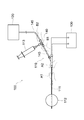
- FIG. 9 shows a catheter system 100 to which a conventional balloon-equipped catheter 110 is applied.
- the catheter system 100 shown in FIG. 9 includes a catheter 110 with a balloon, a stirring device 120 for stirring the liquid in the catheter 110 with a balloon, and a heating device 130 for heating the liquid.
- the catheter 110 with a balloon supplies and discharges liquid to the catheter shaft 111 having a liquid feeding path formed therein, the balloon 112 attached to the tip of the catheter shaft 111, and the liquid feeding path and the balloon 112 of the catheter shaft 111. It has a syringe 113.
- the syringe 113 and the agitator 120 are connected to the catheter shaft 111 via a three-way stopcock 140 and a flexible tube 145. Then, by operating the three-way stopcock 140, either one of the syringe 113 and the stirring device 120 can be communicated with the liquid feeding path of the catheter shaft 111.
- the operation of the catheter 110 with a balloon is very complicated because it is necessary to operate the three-way stopcock 140 and the like while holding the catheter shaft 111 inserted in the patient's body. Therefore, the operation of the balloon-equipped catheter 110 requires a plurality of personnel. For example, as shown by the broken line in FIG. 9, while one person holds the catheter shaft 111 with both hands A1 and A2, another person operates the three-way stopcock 140 and the like with both hands B1 and B2.
- the present invention has been made in consideration of the above points, and an object of the present invention is to provide a catheter with a balloon with improved operability.
- the catheter with a balloon has a housing, a catheter shaft whose base end is arranged in the housing and forms a liquid feeding path communicating with the inside of a balloon attached to the tip, and the liquid feeding path. It is possible to block the supply / discharge line connection portion that has an internal space that communicates and can connect the supply / discharge line that supplies / discharges the liquid to the liquid supply passage through the internal space, and the internal space of the supply / discharge line connection portion. A cock stopper is provided, and the position of the supply / discharge line connection portion is fixed with respect to the housing.
- the catheter with a balloon further includes the supply / discharge line connected to the supply / discharge line connection portion, and a supply / discharge device connected to the supply / discharge line to supply / discharge liquid to the supply / discharge line.
- the supply / discharge line may include a soft tube having a length of 200 mm or more.
- the balloon-equipped catheter has an internal space communicating with the liquid feeding passage, and a stirring line for sucking and discharging the liquid in the liquid feeding passage and stirring the liquid inside the balloon can be connected through the internal space.
- the connection between the internal space of the stirring line connection and the liquid feed path is larger than the connection between the internal space of the supply / discharge line connection and the liquid feed path. It may be located on the tip side.
- the stirring line connection portion may be fixed to the housing.
- the catheter shaft includes an inner cylinder shaft to which the tip of the balloon is fixed and an outer cylinder shaft to which the base end of the balloon is fixed, and the outer cylinder shaft is inside the lumen.
- the cylinder shaft is inserted, the liquid delivery path is formed between the cylinder shaft and the inner cylinder shaft, and the inner cylinder shaft is provided in the housing along a first direction in which the base end portion of the catheter shaft extends.
- An operation unit that extends the balloon by moving it relative to the outer cylinder shaft may be provided.
- the housing is connected to a constricted portion in a direction intersecting the first direction in which the base end portion of the catheter shaft extends, and a constricted portion connected to the constricted portion from one side in the first direction. It may have one grip portion and a second grip portion connected to the constricted portion from the other side in the first direction.
- the catheter shaft includes an inner cylinder shaft to which the tip of the balloon is fixed and an outer cylinder shaft to which the base end of the balloon is fixed, and the outer cylinder shaft is inside the lumen.
- the cylinder shaft is inserted, the liquid feeding path is formed between the cylinder shaft and the inner cylinder shaft, and the maximum outer radius of the first grip portion centered on the axis extending along the first direction is the first direction. It is larger than the maximum outer radius of the second grip portion centered on the axis extending along the axis, and the inner cylinder shaft is relative to the outer cylinder shaft in the first grip portion along the first direction.
- An operation unit that is moved to extend the balloon may be provided.
- the catheter with a balloon includes a housing and a catheter shaft whose base end is arranged in the housing and forms a liquid delivery path communicating with the inside of the balloon attached to the tip.
- the housing includes a constricted portion constricted in a direction intersecting the first direction in which the base end portion of the catheter shaft extends, a first grip portion connected to the constricted portion from one side in the first direction, and the above.
- the constricted portion has a second grip portion connected from the other side in the first direction.
- the catheter with a balloon has a housing, a catheter shaft whose base end is arranged in the housing and forms a liquid feeding path communicating with the inside of the balloon attached to the tip, and the liquid feeding.
- a supply / discharge line connection portion having an internal space communicating with the road and capable of connecting a supply / discharge line for supplying / discharging liquid to the liquid supply passage through the internal space.
- a stirring line connection portion that has an internal space communicating with the liquid feeding path and can connect a stirring line that sucks and discharges the liquid in the liquid feeding path through the internal space and stirs the liquid inside the balloon.
- the connection portion between the internal space of the stirring line connection portion and the liquid supply passage is located on the tip side of the connection portion between the internal space of the supply / discharge line connection portion and the liquid supply passage. ..
- FIG. 5 is a cross-sectional view schematically showing a catheter shaft and a balloon.
- FIG. 5 is a cross-sectional view schematically showing a catheter shaft and a balloon.
- the figure which shows the operation method of the operation part The figure which shows the partial cross-sectional view of the housing along the line II of FIG. 1 together with the movement regulation protrusion part of the operation part.
- FIG. 1 is a diagram for explaining a catheter with a balloon according to the present embodiment.
- FIG. 1 schematically shows the overall configuration of the catheter system 1 to which the balloon-equipped catheter 10 according to the present embodiment is applied.
- the balloon-equipped catheter 10 according to the present embodiment has been devised to improve operability.
- the catheter system 1 shown in FIG. 1 includes a catheter with a balloon (hereinafter, also simply referred to as a “catheter”) 10 from which liquid is supplied and discharged, a stirring line 60 for stirring the liquid in the catheter 10, and a stirring device 65. , A heating device 75 for heating the liquid in the catheter 10.
- a catheter with a balloon hereinafter, also simply referred to as a “catheter”
- a stirring line 60 for stirring the liquid in the catheter 10
- a stirring device 65 for stirring the liquid in the catheter 10
- a heating device 75 for heating the liquid in the catheter 10.
- the catheter 10 includes a catheter shaft 20 having a balloon 15 attached to its tip, a supply / discharge line connection portion 30, a cock stopper 35, a stirring line connection portion 40, an operation unit 50 for extending the balloon 15, and a catheter. It has a housing 55 for accommodating a base end portion of the shaft 20.
- the catheter 10 is further electrically connected to a supply / discharge line 36 connected to the supply / discharge line connection portion 30, a supply / discharge device 38 connected to the supply / discharge line 36, and a heating device 75. It has a heating electrode 70 that heats the liquid in the balloon 15.
- the terms “tip” and “tip” mean, unless otherwise specified, the ends of the catheter 10 that are linearly extended near the tip, respectively.
- the terms “base end” and “base end portion” with respect to the balloon 15, the catheter shaft 20, the operation unit 50 and the housing 55 are referred to as the balloon 15, the catheter shaft, respectively, unless otherwise specified. 20, means the end portion on the side opposite to the tip end of the operation portion 50 and the housing 55.
- FIG. 2 shows a side view of the proximal end portion of the catheter shaft 20.
- FIGS. 3 and 4 show a cross-sectional view schematically showing the structure of the catheter shaft 20.
- FIG. 3 shows a cross section of the catheter shaft 20 in which the balloon 15 is in a liquid and expandable state
- FIG. 4 shows a cross section of the catheter shaft 20 in which the balloon 15 is in an extended state.
- the catheter shaft 20 is formed with a liquid feeding path 21 for feeding a liquid to the balloon 15.
- the liquid delivery path 21 communicates with the inside of the balloon 15.
- the catheter shaft 20 includes an inner cylinder shaft 22 and an outer cylinder shaft 24.
- the inner cylinder shaft 22 is inserted into the inner cavity of the outer cylinder shaft 24.
- the liquid feeding path 21 is formed between the inner cylinder shaft 22 and the outer cylinder shaft 24.
- a guide wire (not shown) for guiding the catheter shaft 20 in the patient's body is inserted into the lumen of the inner cylinder shaft 22.
- the outer cylinder shaft 24 is immovable with respect to the inside of the housing 55.
- the inner cylinder shaft 22 is movable relative to the outer cylinder shaft 24 along the longitudinal direction of the catheter shaft 20.
- the inner cylinder shaft 22 is movable between two positions (the balloon expandable position shown in FIG. 3 and the balloon extension position shown in FIG. 4) with respect to the outer cylinder shaft 24. ..
- An operation unit 50 for moving the inner cylinder shaft 22 relative to the outer cylinder shaft 24 is fixed to the inner cylinder shaft 22.
- the length of the catheter shaft 20 is preferably 0.5 to 2 m from the viewpoint of allowing the balloon 15 to reach the myocardial tissue.
- the diameter of the catheter shaft 20 is preferably 3 to 5 mm from the viewpoint of insertion into the blood vessel.
- the material of the catheter shaft 20 is preferably a flexible material having excellent antithrombotic properties, and examples thereof include, but are not limited to, fluororesin, polyamide resin, polyurethane resin, and polyimide resin.
- the internal space of the balloon 15 communicates with the liquid supply passage 21.
- the tip of the balloon 15 is fixed to the tip of the inner cylinder shaft 22.
- the base end of the balloon 15 is fixed to the tip of the outer cylinder shaft 24. Then, by moving the inner cylinder shaft 22 relative to the outer cylinder shaft 24 along the longitudinal direction of the catheter shaft 20, the balloon 15 can be extended in the direction of the relative movement.
- the diameter of the balloon 15 is preferably 20 to 40 mm from the viewpoint of being able to adhere to the site where the arrhythmia occurs.
- the shape of the balloon 15 is preferably spherical.
- the thickness of the balloon 15 is preferably 20 to 100 ⁇ m.
- a stretchable material having excellent antithrombotic properties is preferable, and a polyurethane-based polymer material is more preferable.
- the polyurethane-based polymer material include thermoplastic polyether urethane, polyether polyurethane urea, fluorine polyether urethane urea, polyether polyurethane urea resin, and polyether polyurethane urea amide.
- the operation unit 50 is fixed to the inner cylinder shaft 22 as shown in FIGS. 2 to 4. Further, the operation unit 50 is movable relative to the housing 55 in the first direction D1 along the proximal end portion of the catheter shaft 20. Therefore, the operation unit 50, together with the inner cylinder shaft 22, can move relative to the housing 55 and the outer cylinder shaft 24 in the first direction D1.
- the base end portion of the inner cylinder shaft 22 extends from the base end portion of the outer cylinder shaft 24, and the base end portion 51 of the operation portion 50 is connected to the base end portion of the inner cylinder shaft 22. There is.
- the tip 52 of the operation unit 50 is exposed to the outside of the housing 55 through the operation unit opening 55a provided in the housing 55, so that the operation unit 50 can be operated from the outside of the housing 55. ing. As shown in FIG. 5, such an operation unit 50 can be operated by the same hand H2 as the hand H2 that grips the housing 55.
- FIG. 6 shows a cross-sectional view showing the housing 55 and the base end portion of the operation unit 50.
- the base end portion 51 of the operation unit 50 has a movement restricting protrusion protruding in the second direction D2 intersecting the first direction D1 which is the movement direction of the operation unit 50. 53 is provided.
- the movement restricting protrusion 53 By engaging the movement restricting protrusion 53 with any of the plurality of movement restricting recesses 56 provided on the inner wall of the housing 55 along the first direction D1, the relative movement of the operation unit 50 with respect to the housing 55 is restricted. .. This allows the balloon 15 to be maintained at a desired length along the longitudinal direction of the catheter shaft 20.
- the engagement between the movement restricting protrusion 53 and the movement restricting recess 56 can be released by elastically deforming the base end portion 51 of the operating portion 50 in the second direction D2.
- the side wall portion 56a facing the first direction D1 of each movement regulation recess 56 is an inclined surface, the movement regulation protrusion 53 and the movement regulation recess 56 are engaged with each other for operation.
- a force directed toward the first direction D1 is applied to the portion 50
- a force directed toward the second direction D2 is applied from the side wall portion 56a to the movement restricting protrusion 53, and the base end portion 51 of the operating portion 50 moves toward the second direction D2. Elastically deforms.
- the movement restricting protrusion 53 moves in the second direction D2, and the engagement between the movement restricting protrusion 53 and the movement restricting recess 56 is released.
- the method of disengaging the movement restricting protrusion 53 and the movement restricting recess 56 is not limited to this.
- the engagement between the movement restricting protrusion 53 and the movement restricting recess 56 may be disengaged, for example, by elastically deforming the housing 55 in the second direction D2.
- the supply / discharge line connection portion 30 is formed in a cylindrical shape and has an internal space 31 that communicates with the liquid supply passage 21 (see FIGS. 3 and 4). The liquid is supplied to and discharged from the liquid supply passage 21 through the internal space 31.
- the supply / discharge line connection portion 30 is connected to the base end portion of the outer cylinder shaft 24, and the position with respect to the housing 55 is fixed.
- the supply / discharge line 36 is connected to the supply / discharge device 38, and the other end is connected to the supply / discharge line connection portion 30.
- the supply / discharge line 36 supplies / discharges liquid to the liquid supply path 21 through the internal space 31 of the supply / discharge line connection portion 30.
- the supply / discharge line 36 includes a soft tube having a length of 200 mm or more.
- the supply / discharge device 38 is connected to the catheter shaft 20 via the supply / discharge line 36 and the supply / discharge line connection portion 30, as shown in FIG.
- the cock plug 35 can be operated by bending the supply / discharge line 36 while holding the supply / discharge device 38 in the connected state.
- the material of the supply / discharge line 36 for example, polyvinyl chloride, polyurethane, silicon, polyamide and the like can be adopted.
- the supply / discharge device 38 supplies / discharges liquid to the supply / discharge line 36.
- the supply / discharge device 38 is a syringe, but is not limited to this.
- the supply / discharge device 38 is provided with a ring 39 for a person who operates the supply / discharge device 38 to pass a finger. This makes it easy to operate the cock stopper 35 and the like while holding the supply / discharge device 38.
- a contrast agent or a contrast agent diluted with physiological saline is preferable so that the balloon 15 inflated with the liquid can be confirmed by an X-ray fluoroscopic image.
- the supply / discharge line 36 and the supply / discharge device 38 may be included in the catheter system 1 and may not be included in the balloon-equipped catheter 10.
- the cock stopper 35 is provided at the supply / discharge line connection portion 30. More specifically, a part of the cock plug 35 is arranged in the internal space 31 of the supply / discharge line connection portion 30, and the cock plug 35 is rotated relative to the supply / discharge line connection portion 30 in a predetermined direction. By arranging it, the internal space 31 of the supply / discharge line connection portion 30 can be closed. In the illustrated example, the cock plug 35 is rotatable between the closed position shown by the solid line in FIG. 2 and the open position shown by the broken line in FIG. When the cock plug 35 is arranged at the closed position, the internal space 31 of the supply / discharge line connection portion 30 is closed, and the communication between the supply / discharge line 36 and the liquid supply passage 21 is cut off. When the cock plug 35 is arranged at the open position, the internal space 31 of the supply / discharge line connection portion 30 is opened, and the supply / discharge line 36 and the liquid supply passage 21 communicate with each other.
- the position of the supply / discharge line connection portion 30 with respect to the housing 55 is fixed. This improves the operability of the cock stopper 35.
- the catheter shaft 20 and the supply / discharge line connecting portion 30 can be retained at the same time.
- the supply / discharge line connection portion 30 can be held by the hand holding the catheter shaft 20. Therefore, it is possible to hold the housing 55 with one hand to hold the catheter shaft 20 and the supply / discharge line connection portion 30, and to operate the cock plug 35 with the other hand. That is, it is possible for a person who operates the catheter shaft 20 to operate the cock plug 35 while retaining the catheter shaft 20.
- the stirring line connecting portion 40 is formed in a cylindrical shape and has an internal space 41 communicating with the liquid feeding path 21 (see FIGS. 3 and 4).
- a stirring line 60 that sucks and discharges the liquid in the liquid feeding path 21 is connected to the stirring line connecting portion 40 through the internal space 41 of the stirring line connecting portion 40.
- the stirring line 60 When the stirring line 60 is connected and the liquid in the liquid feeding path 21 is sucked and discharged, the liquid in the balloon 15 vibrates and is stirred.
- the surface temperature of the balloon 15 can be made uniform, and the affected part can be cauterized uniformly.
- the stirring line 60 is connected to the stirring device 65 to suck and discharge the liquid in the liquid feeding path 21.
- the stirring device 65 periodically sucks and discharges the liquid in the internal space of the stirring line 60.
- the stirring device 65 is preferably a device that repeats suction and discharge of liquid 1 to 5 times per second, and includes a roller pump, a diaphragm pump, a bellows pump, a vane pump, a centrifugal pump, and a pump including a combination of a piston and a cylinder. It is preferred to have a pump selected from the group.
- the stirring line connecting portion 40 is connected to the base end portion of the outer cylinder shaft 24.
- the stirring line connection 40 is fixed to the housing 55. Thereby, by holding the housing 55, the stirring line connecting portion 40 and the stirring line 60 can be held together with the catheter shaft 20.
- the stirring line connecting portion 40 is provided on the tip end side of the catheter shaft 20 with respect to the supply / discharging line connecting portion 30.
- the connection portion between the internal space 41 of the stirring line connection portion 40 and the liquid supply passage 21 is the connection portion between the internal space 31 of the supply / discharge line connection portion 30 and the liquid supply passage 21. It is located closer to the tip of the catheter shaft 20 than the connection. Thereby, the stirring control of the liquid and the supply / discharge control can be performed independently.
- the liquid in the liquid supply passage 21 is sucked and discharged through the internal space 41 of the stirring line connection portion 40 to form a balloon.
- the liquid in 15 can be agitated.
- the stirring line connection portion 40 is not provided with a cock stopper 35.
- the stirring line connecting portion 40 keeps the stirring line 60 and the liquid feeding path 21 in communication with each other at least while the stirring line 60 is connected.
- the heating electrode 70 is fixed to the outer peripheral surface of the inner cylinder shaft 22 inside the balloon 15.
- the tip of the lead wire 71 is connected to the heating electrode 70.
- a connector 72 for electrically connecting the lead wire 71 to the heating device 75 is provided.
- the heating device 75 applies electrical energy to the heating electrode 70 via the lead wire 71 to heat the liquid around the heating electrode 70.
- a high frequency generator capable of generating a high frequency current of 100 Hz or higher can be adopted, but the heating device 75 is not limited to this.
- the lead wire 71 is inserted into the liquid feeding path 21, but the present invention is not limited to this.
- the housing 55 has a constricted portion 57 constricted in a direction intersecting the first direction D1 in which the base end portion of the catheter shaft 20 extends, and one side (base) of the constricted portion 57 in the first direction D1. It has a first grip portion 58 connected from the end side) and a second grip portion 59 connected to the constricted portion 57 from the other side (tip side) of the first direction D1. Since the constricted portion 57 is formed in the housing 55, it is possible to easily hold both the first grip portion 58 and the second grip portion 59.
- FIG. 8 shows a view of the housing 55 from the tip side.
- arrows extending along the direction perpendicular to the paper surface are indicated by symbols with dots in the circle.
- the radius of the maximum circumscribed circle of the first grip portion 58 centered on the axis X1 extending along the first direction D1 (hereinafter, also referred to as “maximum outer radius”). ) R1 is larger than the radius (maximum outer radius) R2 of the maximum circumscribed circle of the second grip portion 59 centered on the axis X2 extending along the first direction D1.
- the first grip portion 58 is provided with an operation portion 50 for extending the balloon 15. This makes it possible to visually convey how to operate the catheter 10. That is, when operating the operation unit 50, it is necessary to apply a relatively large force that can disengage the movement restriction protrusion 53 and the movement restriction recess 56 to the housing 55 and the operation unit 50.
- first grip portion 58 should be firmly gripped and operated as shown in 5. On the other hand, in other cases, it is sufficient to apply a relatively small force to the housing 55, so it is understood that it is sufficient to lightly hold the second grip portion 59 as shown in FIG.
- the inner cylinder shaft 22 is arranged at the balloon extension position shown in FIG. 4, and the balloon 15 is extended. Further, there is no liquid in the balloon 15. Further, the cock plug 35 is arranged at a closed position (position shown by a solid line in FIG. 2), and the internal space 31 of the supply / discharge line connecting portion 30 is closed. Therefore, the communication between the supply / discharge line 36 and the liquid supply path 21 is cut off. Further, the stirring line 60 is connected to the stirring line connecting portion 40, and the heating device 75 is connected to the connection connector 72, but the stirring device 65 and the heating device 75 are not operating.
- the supply / discharge device 38 is gripped by the other hand H2. Then, while holding the supply / discharge device 38 with the other hand H2, the supply / discharge line 36 is curved, and the cock plug 35 is rotated to the open position (the position shown by the broken line in FIG. 2) with the other hand H2. As a result, the supply / discharge line 36 and the liquid supply passage 21 communicate with each other. After that, the supply / discharge device 38 is operated by the other hand H2 to supply the liquid to the inside of the liquid supply passage 21 and the balloon 15.
- the supply / discharge line 36 is curved while the supply / discharge device 38 is held by the other hand H2, and the cock plug is inserted by the other hand H2. Rotate 35 to the closed position. As a result, the internal space 31 of the supply / discharge line connection portion 30 is closed, and the communication between the supply / discharge line 36 and the liquid supply passage 21 is cut off. Then, the stirring device 65 and the heating device 75 are operated to stir the liquid in the balloon 15 while heating it. As a result, the affected area is cauterized. During cauterization, the catheter shaft 20 and / or the second grip portion 59 of the housing 55 is held by one hand H2 and / or both hands H1 and H2 so that the balloon 15 does not separate from the affected part. Is retained for the affected area.
- the liquid in the balloon 15 is continuously stirred by the stirring device 65.
- Supply and discharge Specifically, as shown in FIG. 7, the supply / discharge device 38 is gripped by the other hand H2, the supply / discharge line 36 is curved while holding the supply / discharge device 38, and the cock plug 35 is held by the other hand H2. To the open position. As a result, the liquid feeding path 21 and the supply / discharge line 36 communicate with each other. Then, the supply / discharge device 38 is operated by the other hand H2 to supply / discharge the liquid to the liquid supply passage 21 and the balloon 15.
- the liquid in the balloon 15 continues to be agitated by the agitator 65, so that the temperature on the surface of the balloon 15 is kept uniform. Then, when the amount of liquid in the balloon 15 becomes appropriate, as shown in FIG. 7, while holding the supply / discharge device 38 with the other hand H2, the supply / discharge line 36 is curved, and the cock plug 35 is used with the other hand H2. To the closed position. As a result, the communication between the liquid feeding path 21 and the supply / discharge line 36 is cut off.
- the stirring device 65 and the heating device 75 are stopped. Then, the liquid is discharged from the balloon 15 and the liquid feeding path 21.
- one hand H1 grips the second grip portion 59 of the housing 55
- the other hand H2 grips the supply / discharge device 38 and grips the supply / discharge device 38.
- the supply / discharge line 36 is curved, and the cock plug 35 is rotated to the open position by the other hand H2.
- the water supply / discharge device 38 is operated by the other hand H2 to discharge the liquid from the balloon 15 and the liquid supply path 21.
- the supply / discharge line 36 is curved while holding the supply / discharge device 38 with the other hand H2, and the cock plug 35 is rotated to the closed position with the other hand H2. As a result, the communication between the liquid feeding path 21 and the supply / discharge line 36 is cut off.
- the balloon 15 is extended while holding the second grip portion 59 of the housing 55 with one hand H1. Specifically, as shown in FIG. 5, the first grip portion 58 of the housing 55 is firmly gripped by the other hand H2, and the operation portion 50 is moved to the tip end side of the housing 55 by the fingers of the other hand H2. Let me. As a result, the inner cylinder shaft 22 moves to the balloon extension position shown in FIG. When the balloon 15 is fully extended, the catheter 10 is withdrawn from the pulmonary vein.
- the housing 55 and the base end portion are arranged in the housing 55, and the catheter 10 is communicated with the inside of the balloon 15 attached to the tip end portion.
- a supply / discharge line that has a catheter shaft 20 that forms the liquid passage 21 and an internal space 31 that communicates with the liquid supply passage 21 and can connect a supply / discharge line 36 that supplies / discharges liquid to the liquid supply passage 21 through the internal space 31.
- a connecting portion 30 and a cock plug 35 capable of closing the internal space 31 of the supply / discharge line connecting portion 30 are provided.
- the position of the supply / discharge line connection portion 30 is fixed with respect to the housing 55. According to such a catheter with a balloon 10, the operability of the cock stopper 35 is improved.
- the catheter 10 with a balloon has a supply / discharge line 36 connected to the supply / discharge line connection portion 30 and a supply / discharge device connected to the supply / discharge line 36 to supply / discharge liquid to the supply / discharge line 36. 38 and are further provided.
- the supply / discharge line 36 includes a soft tube having a length of 200 mm or more. According to such a catheter 10 with a balloon, the cock plug while holding the supply / discharge device 38 in a state where the supply / discharge device 38 is connected to the catheter shaft 20 via the supply / discharge line 36 and the supply / discharge line connection portion 30. 35 can be operated.
- the catheter 10 with a balloon has an internal space 41 communicating with the liquid feeding path 21, and sucks and discharges the liquid in the liquid feeding path 21 through the internal space 41 to suck and discharge the liquid inside the balloon 15.
- a stirring line connecting portion 40 to which a stirring line 60 can be connected is further provided. Then, the connection portion between the internal space 41 of the stirring line connection portion 40 and the liquid supply passage 21 is located closer to the tip portion side than the connection portion between the internal space 31 of the supply / discharge line connection portion 30 and the liquid supply passage 21. ing.
- the stirring line connecting portion 40 is fixed to the housing 55. Thereby, by holding the housing 55, the stirring line connecting portion 40 and the stirring line 60 can be held together with the catheter shaft 20.
- the catheter shaft 20 is an inner cylinder shaft 22 to which the tip of the balloon 15 is fixed and an outer cylinder shaft 24 to which the base end of the balloon 15 is fixed.
- the housing 55 is provided with an operation unit 50 for extending the balloon 15 by relatively moving the inner cylinder shaft 22 with respect to the outer cylinder shaft 24 along the first direction D1 in which the base end portion of the catheter shaft 20 extends. Has been done.
- the operation unit 50 can be operated by the same hand H2 as the hand H2 that grips the housing 55.
- the housing 55 has a constricted portion 57 in a direction intersecting the first direction D1 in which the base end portion of the catheter shaft 20 extends, and a constricted portion 57 in the first direction. It has a first grip portion 58 connected from one side of D1 and a second grip portion 59 connected to the constricted portion 57 from the other side of the first direction D1. According to such a catheter 10 with a balloon, the housing 55 is displaced in the first direction D1 from the hand of the person who holds the housing 55 (the person who operates the catheter 10) while holding the housing 55. Can be prevented.
- the catheter shaft 20 is an inner cylinder shaft 22 to which the tip of the balloon 15 is fixed and an outer cylinder shaft 24 to which the base end of the balloon 15 is fixed.
- the maximum outer radius R1 of the first grip portion 58 centered on the axis X1 extending along the first direction D1 is the maximum outside of the second grip portion 59 centered on the axis X2 extending along the first direction D1.
- the first grip portion 58 which is larger than the radius R2, is provided with an operation portion 50 for extending the balloon 15 by moving the inner cylinder shaft 22 relative to the outer cylinder shaft 24 along the first direction D1. .. According to such a catheter 10 with a balloon, it is possible to visually convey how to operate the catheter 10. That is, it is understood that when operating the operation unit 50, the first grip portion 58 should be firmly gripped and operated as shown in FIG. On the other hand, in other cases, it is understood that the second grip portion 59 may be lightly held as shown in FIG.
- the housing 55 and the base end portion are arranged in the housing 55 to form a liquid feeding path 21 communicating with the inside of the balloon 15 attached to the tip end portion.
- the catheter shaft 20 and the like are provided.
- the housing 55 includes a constricted portion 57 constricted in a direction intersecting the first direction D1 in which the base end portion of the catheter shaft 20 extends, and a first grip portion 58 connected to the constricted portion 57 from one side of the first direction D1.
- the constricted portion 57 has a second grip portion 59 connected to the constricted portion 57 from the other side of the first direction D1.
- the housing 55 is displaced in the first direction D1 from the hand of the person who holds the housing 55 (the person who operates the catheter 10) while holding the housing 55. Can be prevented.
- the housing 55 and the base end portion are arranged in the housing 55 to form a liquid feeding path 21 communicating with the inside of the balloon 15 attached to the tip end portion.
- a supply / discharge line connecting portion 30 which has a catheter shaft 20 and an internal space 31 communicating with the liquid supply passage 21 and can connect a supply / discharge line 36 for supplying / discharging liquid to the liquid supply passage 21 through the internal space 31.
- a stirring line connection portion that has an internal space 41 communicating with the liquid passage 21 and can be connected to a stirring line 60 that sucks and discharges the liquid in the liquid feeding passage 21 through the internal space 41 to stir the liquid inside the balloon 15. 40 and.
- connection portion between the internal space 41 of the stirring line connection portion 40 and the liquid supply passage 21 is located closer to the tip portion side than the connection portion between the internal space 31 of the supply / discharge line connection portion 30 and the liquid supply passage 21. ing.
- the liquid in the liquid supply passage 21 is sucked through the internal space 41 of the stirring line connection portion 40. And discharge, the liquid in the balloon 15 can be agitated.
- the surface temperature of the balloon 15 can be maintained uniformly, and uneven cauterization can be prevented from occurring in the affected area. Then, the therapeutic effect can be improved and the burden on the patient can be reduced.
Landscapes
- Health & Medical Sciences (AREA)
- Life Sciences & Earth Sciences (AREA)
- Heart & Thoracic Surgery (AREA)
- Engineering & Computer Science (AREA)
- Public Health (AREA)
- Animal Behavior & Ethology (AREA)
- Veterinary Medicine (AREA)
- General Health & Medical Sciences (AREA)
- Biomedical Technology (AREA)
- Child & Adolescent Psychology (AREA)
- Hematology (AREA)
- Anesthesiology (AREA)
- Pulmonology (AREA)
- Biophysics (AREA)
- Surgery (AREA)
- Molecular Biology (AREA)
- Otolaryngology (AREA)
- Nuclear Medicine, Radiotherapy & Molecular Imaging (AREA)
- Plasma & Fusion (AREA)
- Medical Informatics (AREA)
- Physics & Mathematics (AREA)
- Cardiology (AREA)
- Media Introduction/Drainage Providing Device (AREA)
Abstract
Afin de fournir un cathéter équipé d'un ballonnet ayant une fonctionnalité améliorée, la présente invention concerne un cathéter équipé d'un ballonnet (10) est pourvu de : un boîtier (55) ; une tige de cathéter (20) qui forme un passage d'alimentation en liquide (21), dont la base est disposée dans le boîtier, et qui est en communication avec l'intérieur d'un ballonnet (15) fixé à la pointe de celui-ci ; une partie de raccordement de conduite de distribution/vidange (30) qui comporte un espace interne (31) qui est en communication avec le passage d'alimentation en liquide (21) et qui peut être reliée à une conduite de distribution/vidange (36) qui distribue/vidange un liquide vers/depuis le passage d'alimentation en liquide par l'intermédiaire de l'espace interne ; et un robinet d'arrêt (35) qui est en mesure de boucher l'espace interne de la partie de raccordement de conduite de distribution/vidange (30), la partie de raccordement de conduite de distribution/vidange étant configurée pour avoir une position fixe par rapport au boîtier.
Priority Applications (5)
| Application Number | Priority Date | Filing Date | Title |
|---|---|---|---|
| US17/915,927 US20230141641A1 (en) | 2020-03-31 | 2021-03-31 | Balloon catheter |
| CN202180026449.3A CN115297796A (zh) | 2020-03-31 | 2021-03-31 | 带球囊的导管 |
| EP21780029.1A EP4129381A4 (fr) | 2020-03-31 | 2021-03-31 | Cathéter équipé d'un ballonnet |
| JP2021518813A JPWO2021201076A1 (fr) | 2020-03-31 | 2021-03-31 | |
| KR1020227016557A KR20220159942A (ko) | 2020-03-31 | 2021-03-31 | 벌룬 부착 카테터 |
Applications Claiming Priority (2)
| Application Number | Priority Date | Filing Date | Title |
|---|---|---|---|
| JP2020064360 | 2020-03-31 | ||
| JP2020-064360 | 2020-03-31 |
Publications (1)
| Publication Number | Publication Date |
|---|---|
| WO2021201076A1 true WO2021201076A1 (fr) | 2021-10-07 |
Family
ID=77928991
Family Applications (1)
| Application Number | Title | Priority Date | Filing Date |
|---|---|---|---|
| PCT/JP2021/013778 WO2021201076A1 (fr) | 2020-03-31 | 2021-03-31 | Cathéter équipé d'un ballonnet |
Country Status (7)
| Country | Link |
|---|---|
| US (1) | US20230141641A1 (fr) |
| EP (1) | EP4129381A4 (fr) |
| JP (1) | JPWO2021201076A1 (fr) |
| KR (1) | KR20220159942A (fr) |
| CN (1) | CN115297796A (fr) |
| TW (1) | TW202203859A (fr) |
| WO (1) | WO2021201076A1 (fr) |
Citations (4)
| Publication number | Priority date | Publication date | Assignee | Title |
|---|---|---|---|---|
| JP2008136545A (ja) * | 2006-11-30 | 2008-06-19 | Toray Ind Inc | 温度上昇時間調節可能なバルーン付きアブレーションカテーテルシステム |
| JP2013132364A (ja) * | 2011-12-26 | 2013-07-08 | Nippon Erekuteru:Kk | バルーンカテーテル |
| JP2014180498A (ja) * | 2013-03-21 | 2014-09-29 | Japan Lifeline Co Ltd | 電極カテーテルおよびその製造方法 |
| JP5913739B2 (ja) | 2013-10-04 | 2016-04-27 | 有限会社日本エレクテル | バルーンカテーテルアブレーションシステム |
Family Cites Families (5)
| Publication number | Priority date | Publication date | Assignee | Title |
|---|---|---|---|---|
| TWI517833B (zh) * | 2009-03-31 | 2016-01-21 | 東麗股份有限公司 | 附有氣球之電燒導管用軸及附有氣球之電燒導管系統 |
| JP5444840B2 (ja) * | 2009-05-21 | 2014-03-19 | 東レ株式会社 | バルーン付きアブレーションカテーテル及びバルーン付きアブレーションカテーテルシステム |
| US8911434B2 (en) * | 2010-10-22 | 2014-12-16 | Medtronic Cryocath Lp | Balloon catheter with deformable fluid delivery conduit |
| JP5500273B1 (ja) * | 2012-07-05 | 2014-05-21 | 有限会社日本エレクテル | バルーンカテーテルシステム |
| JP2015104485A (ja) * | 2013-11-29 | 2015-06-08 | オリンパスメディカルシステムズ株式会社 | カテーテル |
-
2021
- 2021-03-31 CN CN202180026449.3A patent/CN115297796A/zh active Pending
- 2021-03-31 JP JP2021518813A patent/JPWO2021201076A1/ja active Pending
- 2021-03-31 US US17/915,927 patent/US20230141641A1/en active Pending
- 2021-03-31 KR KR1020227016557A patent/KR20220159942A/ko unknown
- 2021-03-31 WO PCT/JP2021/013778 patent/WO2021201076A1/fr unknown
- 2021-03-31 TW TW110111785A patent/TW202203859A/zh unknown
- 2021-03-31 EP EP21780029.1A patent/EP4129381A4/fr active Pending
Patent Citations (4)
| Publication number | Priority date | Publication date | Assignee | Title |
|---|---|---|---|---|
| JP2008136545A (ja) * | 2006-11-30 | 2008-06-19 | Toray Ind Inc | 温度上昇時間調節可能なバルーン付きアブレーションカテーテルシステム |
| JP2013132364A (ja) * | 2011-12-26 | 2013-07-08 | Nippon Erekuteru:Kk | バルーンカテーテル |
| JP2014180498A (ja) * | 2013-03-21 | 2014-09-29 | Japan Lifeline Co Ltd | 電極カテーテルおよびその製造方法 |
| JP5913739B2 (ja) | 2013-10-04 | 2016-04-27 | 有限会社日本エレクテル | バルーンカテーテルアブレーションシステム |
Non-Patent Citations (1)
| Title |
|---|
| See also references of EP4129381A4 |
Also Published As
| Publication number | Publication date |
|---|---|
| EP4129381A4 (fr) | 2024-04-24 |
| US20230141641A1 (en) | 2023-05-11 |
| KR20220159942A (ko) | 2022-12-05 |
| TW202203859A (zh) | 2022-02-01 |
| EP4129381A1 (fr) | 2023-02-08 |
| JPWO2021201076A1 (fr) | 2021-10-07 |
| CN115297796A (zh) | 2022-11-04 |
Similar Documents
| Publication | Publication Date | Title |
|---|---|---|
| JP6654228B2 (ja) | 組織拡張デバイス、システムおよび方法 | |
| US5843152A (en) | Catheter system having a ball electrode | |
| US20070179496A1 (en) | Flexible catheter for ablation therapy | |
| EP2193819B1 (fr) | Prévention de coudes dans des tuyaux d'irrigation de cathéters | |
| CN103860265A (zh) | 具有导向线的环状标测导管 | |
| WO1996035464A1 (fr) | Injecteur peripherique transluminal | |
| WO2008112870A2 (fr) | Cathéter d'ablation épicardique et procédé d'utilisation | |
| US20220008690A1 (en) | Medical device flushing systems and methods | |
| US11364370B2 (en) | Multi-purpose balloon catheter for intra cavity radiation delivery | |
| US20190255292A1 (en) | Deflectable sheath with inflatable balloon | |
| US20240081906A1 (en) | Systems and methods for energy delivery | |
| US20210267794A1 (en) | Miniaturized Intra-Body Controllable Cold Therapy Medical Devices and Methods | |
| WO2021201076A1 (fr) | Cathéter équipé d'un ballonnet | |
| CN210301984U (zh) | 一种可调节硬度的导管及介入装置 | |
| US11918278B2 (en) | Medical delivery systems and methods of using the same | |
| EP3705072A1 (fr) | Ablation thermique résistive pour le traitement de l'anatomie | |
| US20200168360A1 (en) | Systems and methods for energy delivery | |
| JP2017080142A (ja) | 内視鏡用高周波処置具 | |
| WO2024095151A1 (fr) | Appareil de cryo-distribution | |
| WO2022187821A1 (fr) | Dispositif et procédé de modulation thermique de tissu | |
| KR100849228B1 (ko) | 생체 삽입용 의료기기의 유도기구 | |
| CN117479898A (zh) | 具有远侧可铰接部段的医疗装置 | |
| JP2019097760A (ja) | カテーテル | |
| JPH0626895U (ja) | カテーテル組立体およびカテーテル把持部材 |
Legal Events
| Date | Code | Title | Description |
|---|---|---|---|
| ENP | Entry into the national phase |
Ref document number: 2021518813 Country of ref document: JP Kind code of ref document: A |
|
| 121 | Ep: the epo has been informed by wipo that ep was designated in this application |
Ref document number: 21780029 Country of ref document: EP Kind code of ref document: A1 |
|
| NENP | Non-entry into the national phase |
Ref country code: DE |
|
| ENP | Entry into the national phase |
Ref document number: 2021780029 Country of ref document: EP Effective date: 20221031 |