WO2021200870A1 - 成形体、吸音材、及び振動吸収材 - Google Patents
成形体、吸音材、及び振動吸収材 Download PDFInfo
- Publication number
- WO2021200870A1 WO2021200870A1 PCT/JP2021/013396 JP2021013396W WO2021200870A1 WO 2021200870 A1 WO2021200870 A1 WO 2021200870A1 JP 2021013396 W JP2021013396 W JP 2021013396W WO 2021200870 A1 WO2021200870 A1 WO 2021200870A1
- Authority
- WO
- WIPO (PCT)
- Prior art keywords
- cavity
- neck
- molded body
- neck portion
- molded product
- Prior art date
- Legal status (The legal status is an assumption and is not a legal conclusion. Google has not performed a legal analysis and makes no representation as to the accuracy of the status listed.)
- Ceased
Links
Images


Classifications
-
- G—PHYSICS
- G10—MUSICAL INSTRUMENTS; ACOUSTICS
- G10K—SOUND-PRODUCING DEVICES; METHODS OR DEVICES FOR PROTECTING AGAINST, OR FOR DAMPING, NOISE OR OTHER ACOUSTIC WAVES IN GENERAL; ACOUSTICS NOT OTHERWISE PROVIDED FOR
- G10K11/00—Methods or devices for transmitting, conducting or directing sound in general; Methods or devices for protecting against, or for damping, noise or other acoustic waves in general
- G10K11/16—Methods or devices for protecting against, or for damping, noise or other acoustic waves in general
- G10K11/172—Methods or devices for protecting against, or for damping, noise or other acoustic waves in general using resonance effects
-
- E—FIXED CONSTRUCTIONS
- E04—BUILDING
- E04B—GENERAL BUILDING CONSTRUCTIONS; WALLS, e.g. PARTITIONS; ROOFS; FLOORS; CEILINGS; INSULATION OR OTHER PROTECTION OF BUILDINGS
- E04B1/00—Constructions in general; Structures which are not restricted either to walls, e.g. partitions, or floors or ceilings or roofs
- E04B1/62—Insulation or other protection; Elements or use of specified material therefor
- E04B1/74—Heat, sound or noise insulation, absorption, or reflection; Other building methods affording favourable thermal or acoustical conditions, e.g. accumulating of heat within walls
- E04B1/82—Heat, sound or noise insulation, absorption, or reflection; Other building methods affording favourable thermal or acoustical conditions, e.g. accumulating of heat within walls specifically with respect to sound only
- E04B1/84—Sound-absorbing elements
- E04B1/8404—Sound-absorbing elements block-shaped
-
- G—PHYSICS
- G10—MUSICAL INSTRUMENTS; ACOUSTICS
- G10K—SOUND-PRODUCING DEVICES; METHODS OR DEVICES FOR PROTECTING AGAINST, OR FOR DAMPING, NOISE OR OTHER ACOUSTIC WAVES IN GENERAL; ACOUSTICS NOT OTHERWISE PROVIDED FOR
- G10K11/00—Methods or devices for transmitting, conducting or directing sound in general; Methods or devices for protecting against, or for damping, noise or other acoustic waves in general
- G10K11/16—Methods or devices for protecting against, or for damping, noise or other acoustic waves in general
- G10K11/162—Selection of materials
-
- B—PERFORMING OPERATIONS; TRANSPORTING
- B60—VEHICLES IN GENERAL
- B60R—VEHICLES, VEHICLE FITTINGS, OR VEHICLE PARTS, NOT OTHERWISE PROVIDED FOR
- B60R13/00—Elements for body-finishing, identifying, or decorating; Arrangements or adaptations for advertising purposes
- B60R13/08—Insulating elements, e.g. for sound insulation
-
- E—FIXED CONSTRUCTIONS
- E04—BUILDING
- E04B—GENERAL BUILDING CONSTRUCTIONS; WALLS, e.g. PARTITIONS; ROOFS; FLOORS; CEILINGS; INSULATION OR OTHER PROTECTION OF BUILDINGS
- E04B1/00—Constructions in general; Structures which are not restricted either to walls, e.g. partitions, or floors or ceilings or roofs
- E04B1/62—Insulation or other protection; Elements or use of specified material therefor
- E04B1/74—Heat, sound or noise insulation, absorption, or reflection; Other building methods affording favourable thermal or acoustical conditions, e.g. accumulating of heat within walls
- E04B1/82—Heat, sound or noise insulation, absorption, or reflection; Other building methods affording favourable thermal or acoustical conditions, e.g. accumulating of heat within walls specifically with respect to sound only
- E04B1/84—Sound-absorbing elements
- E04B2001/8457—Solid slabs or blocks
- E04B2001/8476—Solid slabs or blocks with acoustical cavities, with or without acoustical filling
- E04B2001/848—Solid slabs or blocks with acoustical cavities, with or without acoustical filling the cavities opening onto the face of the element
- E04B2001/8485—Solid slabs or blocks with acoustical cavities, with or without acoustical filling the cavities opening onto the face of the element the opening being restricted, e.g. forming Helmoltz resonators
Definitions
- This disclosure relates to a molded body, a sound absorbing material and a vibration absorbing material.
- Patent Document 1 describes a sound absorbing material including a matrix resin forming a base material and a fibrous substance dispersed inside the matrix resin.
- the matrix resin is composed of open cell foam containing a thermoplastic resin.
- the matrix resin has a plurality of bubbles inside, and the fibrous substance has a hollow portion that communicates the plurality of bubbles with each other.
- the hollow portion constitutes a sound absorbing mechanism similar to Helmholtz resonance, and the sound absorbing mechanism absorbs low-frequency sound.
- the fibrous material has a bent tubular shape and extends from one bubble to another bubble adjacent to the one bubble. Each of one end and the other end of the fibrous material protrudes from the bubble wall surface that defines the bubble.
- the molded body containing the above-mentioned sound absorbing material is used for a transport aircraft such as an automobile or a building such as a house.
- a transport aircraft such as an automobile or a building such as a house.
- further noise reduction is required, and the need for noise reduction is increasing.
- stricter noise regulations have been formulated in recent years, and it is required to further improve the sound absorption performance required by the noise regulations.
- the molded body is made thicker, it is possible to improve the sound absorption performance and the vibration absorption performance.
- the molded body is thick, there is a concern that sufficient space cannot be secured in a transport aircraft, a building, or the like. Therefore, a molded product that can improve the sound absorption performance and the vibration absorption performance and suppress the increase in size is desired.
- the molded body according to the present disclosure includes a plurality of cavities formed inside a molding material, and a plurality of neck portions provided in each of the plurality of cavities and communicating with the cavities, and the plurality of neck portions.
- a part of the cavity communicates with the surface and / or the cavity exposed on the surface, and at least a part of the neck portions communicates with each other and the inner surface of the neck portion. Is formed by the molding material itself.
- a molded body a sound absorbing material and a vibration absorbing material which can enhance the sound absorbing performance and the vibration absorbing performance and suppress the increase in size.
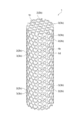
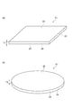
- FIG. 1 is a perspective view showing an exemplary molded product according to an embodiment.
- FIG. 2 is a diagram showing a cavity portion and a neck portion exposed on the surface of the molded product of FIG.
- FIG. 3 is a cross-sectional view of the molded body schematically showing the internal structure of the molded body of FIG.
- FIG. 4 is a cross-sectional view of a molded body schematically showing an internal structure of an exemplary molded body according to a modified example.
- FIG. 5 is a perspective view schematically showing the appearance of the hollow portion and the neck portion of FIG.
- FIG. 6 is an exemplary graph showing the relationship between the frequency of sound waves with respect to the molded product and the vertically incident sound absorption coefficient for each urethane foam material of the molded product.
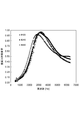
- FIG. 7 is an exemplary graph showing the relationship between the frequency of sound waves with respect to the molded body and the vertically incident sound absorption coefficient for each diameter of the neck portion.
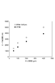
- FIG. 8 is an exemplary graph showing the relationship between the diameter of the neck portion and the peak frequency of sound waves.
- FIG. 9 is an exemplary graph showing the relationship between the frequency of sound waves with respect to the molded body and the vertically incident sound absorption coefficient for each diameter of the cavity.
- FIG. 10 is an exemplary graph showing the relationship between the frequency of sound waves with respect to the molded product and the vertically incident sound absorption coefficient for each resin material of the molded product.
- 11 (a) and 11 (b) are perspective views showing the outer shape of an exemplary molded product.
- FIG. 12 is a cross-sectional view of a molded body schematically showing an example of the internal structure of the molded body according to the modified example.
- FIG. 13 (a) is an enlarged view showing an example of ribs between a pair of large cells
- FIG. 13 (b) is an enlarged view of a portion shown in “A” of FIG. 13 (a).
- 14 (a) is a photograph of the molded product according to the comparative example
- FIGS. 14 (b) and 14 (c) are photographs of the observation results of the molded product according to the example.
- 15 (a) and 15 (b) are schematic views showing how a neck portion is formed by inserting a needle-shaped member into the foam.
- FIG. 13 (a) is an enlarged view showing an example of ribs between a pair of large cells
- FIG. 13 (b) is an enlarged view of a portion shown in “A” of FIG. 13 (a).
- 14 (a) is a photograph of the molded product according to the comparativ
- FIG. 16 is a cross-sectional view of a molded body schematically showing an example of the internal structure of the molded body according to the modified example.
- 17 (a) and 17 (b) are enlarged cross-sectional views of a molded product schematically showing an example of the internal structure of the molded product.
- FIG. 18 is an enlarged cross-sectional view of a molded product schematically showing an example of the internal structure of the molded product according to the comparative example.
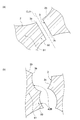
- FIG. 19 (a) is a schematic view for explaining the protruding portion of the neck portion of the molded product according to the embodiment and the modified example
- FIG. 19 (b) is a schematic view for explaining the protruding portion of the neck portion of the molded product according to the comparative example. It is a schematic diagram for demonstrating the part. It is a schematic diagram for demonstrating the setting range of a parameter.
- a plurality of cavities are formed inside, and a neck portion is formed in each of the plurality of cavities.
- a portion of the plurality of necks communicates with the surface and / or cavities exposed to the surface. At least a part of the plurality of necks communicates the plurality of cavities with each other. Therefore, when vibration energy including sound waves is incident on the neck portion, violent vibration is generated, and the cavity portion on the opposite side of the surface functions as a spring, so that the vibration energy is viscously attenuated. Therefore, high sound absorption performance and vibration absorption performance can be exhibited by the neck portion and the hollow portion that expands on the side opposite to the surface of the neck portion.
- the inner surface of the neck portion is formed by the molding material itself.
- the incident of vibration energy into the cavity and the neck can be made smoother than in the case where the neck is formed of a separate dedicated member. Therefore, the sound absorption performance and the vibration absorption performance can be improved without increasing the size of the molded body. As a result, it is possible to suppress an increase in the size of the molded product.
- the cavity portion and the neck portion communicating with the cavity portion may be integrally formed of the same molding material. In this case, since the molded product can be produced from a single material, the molded product can be easily produced.
- the molded body is a foam, and the cavity may be formed by cells inside the foam that are 100% or more larger than the average diameter of the entire cell. In this case, a large cell can form a cavity having a sufficient size.
- At least a part of the neck part may be formed by cells inside the foam.
- the neck portion can be easily formed without using a dedicated member for providing the neck portion.
- At least a part of the neck portion may have a shape in which the center line extends linearly. In this case, the vibration energy can be smoothly incident on the neck portion.
- the plurality of cavities and the plurality of necks form a wavelength absorption unit, and the wavelength absorption rate of 450 Hz or more and 10,000 Hz or less in the wavelength absorption unit may be 0.4 or more.
- the sound wave energy and vibration energy in the frequency band of 450 Hz or higher and 10000 Hz or lower can be absorbed with higher efficiency.
- the vertical incident sound absorption coefficient per 10 mm thickness of 450 Hz or more and 10000 Hz or less may be 0.4 or more.
- the sound wave energy and vibration energy in the frequency band of 450 Hz or higher and 10000 Hz or lower can be absorbed with higher efficiency.
- the diameter of the neck portion may be 10 ⁇ m or more and 1000 ⁇ m or less. In this case, the sound wave energy and the vibration energy in the target frequency band can be absorbed more efficiently.
- the volume of the cavity may be 4.19 ⁇ 10 9 ⁇ m 3 or more and 3.82 ⁇ 10 11 ⁇ m 3 or less. In this case, the sound wave energy and the vibration energy in the target frequency band can be absorbed more efficiently.
- the protruding height of the protruding portion with respect to the inner surface of the hollow portion may be 100 ⁇ m or less.
- the incident of vibration energy into the cavity and the neck can be made smoother.
- the molded body described above includes a main surface, a back surface provided so as to face the main surface, and one or more side surfaces provided between the main surface and the back surface, and the main surface or the main surface is provided. A part of a plurality of neck portions may be exposed in the exposed cavity portion.
- the sound absorbing material according to the present disclosure may be the above-mentioned molded product. In this case, it is possible to provide a sound absorbing material having the same effect as described above.
- the vibration absorber according to the present disclosure may be the above-mentioned molded product. In this case, it is possible to provide a vibration absorber having the same effect as described above.
- the molded body according to the present disclosure includes a plurality of cavities formed inside and a plurality of neck portions provided in each of the plurality of cavities and communicating with the cavities, and among the plurality of neck portions.
- a part communicates with the surface and / or a cavity exposed on the surface, at least a part of the plurality of necks communicates with each other, and the neck communicates with the cavity. It extends from the defining inner surface to the surface or the inner surface of another cavity adjacent to the cavity.
- a plurality of cavities are formed inside, and a neck portion is formed in each of the plurality of cavities.
- a portion of the plurality of necks communicates with the surface and / or cavities exposed to the surface. At least a part of the plurality of necks communicates the plurality of cavities with each other. Therefore, when vibration energy including sound waves is incident on the neck portion, violent vibration is generated, and the cavity portion on the opposite side of the surface functions as a spring, so that the vibration energy is viscously attenuated. Therefore, high sound absorption performance and vibration absorption performance can be exhibited by the neck portion and the hollow portion that expands on the side opposite to the surface of the neck portion.
- the neck portion extends from the inner surface defining the cavity portion to the inner surface of another cavity portion adjacent to the cavity portion. Therefore, since the neck portion can be formed so as not to protrude from the inner surface that defines the cavity portion, the incident of vibration energy into the cavity portion and the neck portion can be made smoother. Therefore, the sound absorption performance and the vibration absorption performance can be improved without increasing the size. As a result, it is possible to suppress an increase in the size of the molded product.
- the material of the cavity and the material of the neck may be the same as each other. In this case, since the molded product can be produced from a single material, the molded product can be easily produced.
- the ratio of the number of neck portions to the number of hollow portions may be 1.1 or more.
- the frictional action between the vibration including the sound waves and the neck portions can be strengthened, so that the sound wave energy and the vibration energy can be absorbed more efficiently.
- the molded product described above may contain urethane foam at least in part. In this case, it is possible to provide a molded product having high flexibility.
- the molded product described above may contain at least one of a thermoplastic resin and a photocurable resin.
- the molded body can be manufactured by a 3D printer or the like, the molded body can be manufactured more easily.
- the air permeability may be 0.4 cm 3 / (cm 2 ⁇ s) or more and 200 cm 3 / (cm 2 ⁇ s) or less. In this case, the sound absorption performance and the vibration absorption performance can be enhanced, and the desired air permeability can be ensured.
- the thickness may be 5 mm or more. In this case, the sound absorption performance and the vibration absorption performance can be improved more reliably.
- a molded body a sound absorbing material and a vibration absorbing material which can enhance the sound absorbing performance and the vibration absorbing performance and suppress the increase in size.
- the "molded article” in the present disclosure refers to a molded article molded into a certain shape.
- the molded product according to the present disclosure includes a plurality of hollow portions and a plurality of neck portions.
- the "cavity portion” indicates a portion forming a space inside the molded product.
- the "neck portion” is provided in each of the plurality of cavities and indicates a portion communicating with the cavities.
- the “neck” may communicate with the surface of the part and / or the cavity exposed on the surface.
- the molded body may include a plurality of "neck portions", and at least a part of the plurality of neck portions may communicate the plurality of cavities with each other.
- the volume of the void in the "neck portion” may be smaller than the volume of the cavity portion, and the "neck portion” may be a void connecting a plurality of cavity portions to each other.
- a “wavelength absorption unit” can be formed by the cavity and the neck.
- the “wavelength absorption unit” indicates a portion capable of selectively absorbing sound or vibration of a specific wavelength, and constitutes, for example, a resonator type sound absorbing material.
- the "resonator type sound absorbing material” is composed of a hole (for example, a neck portion) exposed on the surface of the molded body and an expansion portion (for example, a cavity portion) that extends beyond the hole at a portion opposite to the surface of the hole.
- a molded body that absorbs sound of a target frequency hereinafter, also referred to as a “target frequency” is shown.
- the "wavelength absorption unit” may be, for example, a Helmholtz resonator.
- the relationship between the target frequency (resonance frequency) f 0 (Hz), the diameter d (m) of the hole (for example, the neck portion), and the volume V (m 3 ) of the expansion portion (for example, the cavity portion) is described in the formula described later. It is represented by (1). Note that S indicates the cross-sectional area (m 2 ) of the opening exposed on the surface of the molded body, l indicates the thickness of the material (m), and C indicates the speed of sound (m / s). For example, by using the above equation (1), it is possible to effectively absorb the sound wave energy and the vibration energy of the target frequency.
- FIG. 1 is a perspective view showing an exemplary molded body 1.
- the molded body 1 is, for example, a sound absorbing material that absorbs sound wave energy.
- the molded body 1 may be a sound absorbing material provided for suppressing noise inside the automobile or suppressing noise outside the automobile.
- the molded body 1 may be a sound absorbing material provided for soundproofing of a building including a house.
- the molded body 1 as the sound absorbing material can be used for various purposes.
- the molded body 1 may be a vibration absorbing material that absorbs vibration energy.
- the molded body 1 exhibits a columnar shape.
- the shape of the molded body 1 is not limited to the columnar shape and can be changed as appropriate.
- the molded body 1 is made of, for example, urethane foam having open cell properties.
- the molded body 1 may be manufactured by urethane molding.
- the molded body 1 may be made of a thermoplastic resin or a photocurable resin.
- the molded body 1 is manufactured by, for example, a 3D printer or the like.
- the molded product 1 may be made of polyvinyl chloride or a metal.
- the molded body 1 may be produced by at least one of laser irradiation, insertion of a needle-shaped member, blowing of gas, and mixing of volatile components.
- the material and manufacturing method of the molded product 1 are not particularly limited. Alternatively, a large molded product may be prepared, and the prepared molded product may be cut into pieces to obtain a molded product having a desired size and shape.
- the molded body 1 includes a plurality of cavity portions 2 and a plurality of neck portions 3.
- the plurality of cavities 2 are dispersedly arranged inside the molded body 1, for example.
- a plurality of cavities are arranged in a dispersed manner means that, for example, a plurality of cavities 2 are arranged in a staggered pattern on a cut surface of a molded body 1 shown in FIG. A state in which the portions 2 are arranged in a grid pattern and a state in which a plurality of cavity portions 2 are arranged in a concentric manner are included.
- the cavity 2 is exposed on each of the end face 1c and the side surface 1d of the molded body 1.
- the cavity 2 may be exposed on all surfaces of the molded body 1, may be exposed on a part of the surfaces of the molded body 1, or may not be exposed on any surface. May be good.
- a part of the plurality of neck portions 3 may communicate (expose) with the surface 1b and / or the cavity portion 2 exposed on the surface 1b of the molded body 1.
- the cavities 2 may be arranged regularly or irregularly.
- the neck portion 3 has, for example, an opening 3b on the inner surface 2b of the cavity portion 2.
- the opening 3b has, for example, a circular shape.
- the shape of the opening 3b is not limited to a circular shape, and may be an oval shape or the like, and is not particularly limited.
- the openings 3b of the neck portion 3 may be regularly arranged on the inner surface 2b or may be irregularly arranged.
- the "inner surface” of the cavity refers to the inner surface that defines the cavity.
- An “opening” refers to a mouth that is exposed outward from the surface of something.
- the inner surface 2b exposed to the surface 1b exhibits, for example, a hemisphere.
- the shape of the inner surface 2b is not limited to a hemisphere, and is not particularly limited.
- the sizes (areas) of the plurality of inner surfaces 2b exposed on the surface 1b are different from each other. That is, the size of the inner surface 2b exposed on the surface 1b is different.
- FIG. 2 is a diagram showing an inner surface 2b of the cavity 2 of the molded body 1 and an opening 3b of the neck 3.
- the cavities 2 may be regularly arranged on the surface 1b, for example, in a staggered pattern.
- three openings 3b are formed on one inner surface 2b.
- the diameters of the openings 3b may be the same as each other, for example. However, the diameters of the openings 3b may be different from each other. When the diameters of the openings 3b are different from each other, for example, if the diameter of the first opening 3b is D (mm), the diameter of the second opening 3b is D / 2 (mm) and the diameter of the third opening 3b. May be D / 4 (mm). As an example, the value of D is 0.4, but is not particularly limited.
- FIG. 3 is a cross-sectional view schematically showing the internal structure of the molded body 1.
- a plurality of cavity portions 2 and a plurality of neck portions 3 that communicate the plurality of cavity portions 2 with each other are formed in the inner 1f of the molded body 1.
- the neck portion 3 may be from the inner surface 2b defining the cavity 2 to the inner surface 2b of another cavity 2 adjacent to the cavity 2 (the inner surface 2b of the cavity 2 exposed on the surface 1b).
- the surface 1b (for example, when the cavity 2 is formed on the surface 1b, the region other than the region where the cavity 2 is formed) extends.
- the neck portion 3 extends from the inner surface 2b that defines the cavity portion 2 as the starting point and the inner surface 2b or the surface 1b of another cavity portion 2 adjacent to the cavity portion 2 as the ending point. In other words, the neck portion 3 does not extend inside the cavity portion 2. However, on the inner surface 2b of the cavity portion 2, minute steps, protrusions, ridges, etc. that do not significantly impair the sound absorption performance and the vibration absorption performance may be formed from the neck portion 3 toward the inside of the cavity portion 2. .. A detailed description of the configuration will be described later while comparing with a comparative example.
- the molded body 1 may be a porous sound absorbing material.
- sound absorption is performed by converting the sound wave energy incident on the neck portion 3 into heat energy.
- the sound wave energy is attenuated by friction in the void (neck portion 3) and absorbed by the skeletal vibration of the molded body 1 itself.
- the plurality of cavity portions 2 and the plurality of neck portions 3 may form the wavelength absorption unit 10 of the molded body 1.
- the wavelength absorption unit 10 constitutes, for example, a resonator type sound absorbing material.
- the neck portion 3 exposed on the surface 1b (inner surface 2b of the cavity portion 2) of the molded body 1 and the cavity portion 2 wider than the neck portion 3 in the portion opposite to the opening 3b of the neck portion 3 Absorbs sound waves or vibrations of the target frequency.
- the material of the cavity portion 2 and the material of the neck portion 3 are the same as each other.
- the material of the cavity portion 2 and the material of the neck portion 3 may contain a thermoplastic resin or a photocurable resin.
- the cavity portion 2 and the neck portion 3 can be easily manufactured by using a 3D printer or the like.
- the material of the cavity 2 and the material of the neck 3 may be different from each other.
- the inner surface 2b of the cavity 2 is exposed on the surface 1b of the molded body 1, but the opening 3b of the neck portion 3 may be exposed on the surface 1b of the molded body 1.
- the cavity 2 and the neck 3 are both three-dimensionally formed.
- “Formed three-dimensionally” means, for example, the first direction of the molded body, the second direction intersecting the first direction (orthogonal as an example), and intersecting both the first direction and the second direction. It shows a state in which they are arranged along each of the third directions (orthogonal as an example).
- the cavity portion 2 and the neck portion 3 are arranged so as to be arranged along the first direction, the second direction, and the third direction, respectively.
- each of the cavity portion 2 and the neck portion 3 is arranged so as to extend along the depth direction D of the molded body 1 and to line up along the depth direction D.
- FIG. 5 is a perspective view schematically showing the appearance of the cavity portion 2 and the appearance of the neck portion 3.
- the hollow portion 2 has a spherical shape
- the neck portion 3 has a cylindrical hole shape.
- the cavity 2 may have a shape other than a spherical shape, and may have a rectangular parallelepiped shape, a cubic shape, a polyhedral shape, an egg shape, an ellipsoidal shape, an oval shape, a dome shape, or the like.
- the neck portion 3 may have a shape other than the cylindrical hole shape.
- the neck portion 3 may have any shape as long as it has a gap having a volume smaller than that of the cavity portion 2 and has two or more openings communicating with the gap.
- the neck portion 3 has a hollow cylindrical shape (cylindrical hole shape); a hollow prism shape such as a hollow triangular pillar, a hollow square pillar, a hollow pentagonal pillar; Hollow pyramidal trapezoidal shape such as pedestal; spherical; irregular hollow shape; etc. may be exhibited.
- the neck portion 3 may or may not have a bent portion, a bent portion, a bent portion or a curved portion.
- the neck portion 3 may or may not have a branch.
- the opening 3b of the neck portion 3 is exposed on, for example, the inner surface 2b that defines the cavity portion 2.
- the neck portion 3 extends from the inner surface 2b that defines one cavity 2 to the inner surface 2b of another cavity 2 adjacent to the one cavity 2.
- the sizes of the plurality of neck portions 3 extending from the inner surface 2b may be the same as each other or may be different from each other.
- the opening 3b of the neck portion 3 may be exposed on the surface 1b of the molded body 1 instead of the hollow portion 2.
- any one of the plurality of neck portions 3 communicates with the surface 1b of the molded body 1.
- FIG. 5 shows an example in which the sizes (for example, diameters) of the plurality of neck portions 3 are the same as each other.
- the plurality of neck portions 3 may include a large neck portion 3, a medium-sized neck portion 3, and a small neck portion 3. As described above, the size of the neck portion 3 and the number of types of the size of the neck portion 3 can be appropriately changed.
- the neck portion 3 does not have a portion protruding from the inner surface 2b.
- the cavity portion 2 may have a hexagonal close-packed structure. In this case, as many cavities 2 as possible can be arranged inside the molded body 1, so that the sound absorbing performance and the vibration absorbing performance of the molded body 1 can be further improved.
- a plurality of neck portions 3 may extend radially from the spherical cavity portion 2.
- the angle ⁇ formed by the one neck portion 3 extending from the cavity portion 2 and the neck portion 3 adjacent to the one neck portion 3 is 120 °.
- the value of the angle ⁇ is not particularly limited.
- the molded body 41 is a foamed body 45 in which a large number of cells are formed by foaming the molding material.
- a plurality of cells 42 are formed inside the molding resin by the bubbles.
- the cavity 2 is formed by some of the many cells 42 inside the foam 45. As shown in FIG. 12, the cavity is formed by one large cell 42 (referred to as large cell 42A). At least a part of the neck portion 3 is formed by the cell 42 inside the foam 45, and the neck portion 3 is formed by a cell 42 (referred to as a small cell 42B) smaller than the large cell 42A of the cavity portion 2. Will be done.
- the small cell 42B when a small cell 42B existing between one large cell 42A and another large cell 42A communicates with each large cell 42A, the small cell 42B functions as a neck portion 3. Further, as shown by "A" in the figure, a plurality of small cells 42B may communicate with each other so as to be connected between the pair of large cells 42A. In this way, one neck portion 3 may be formed by the plurality of small cells 42B.
- the small cell 42B existing between one large cell 42A and the surface 41a of the molded body 41 (foam 45) communicates with the large cell 42A and the surface 41a, the small cell 42B also functions as a neck portion.
- the small cell 42B may function as a part of the volume of the cavity 2.
- a thin rib 43 is formed.
- a fine cell 42C smaller than the small cell 42B may be formed in the thin rib 43.
- the neck portion 3 may be formed by the aggregation of the fine cells 42C.
- the defoaming agent is mixed in the foam molding resin and diffused inside the molding material.
- the foam 45 is molded by performing the adjustment, a portion where the bubbles become large is formed due to the influence of the defoaming agent.
- large cells 42A are randomly formed in the form of being mixed in the small cells 42B.
- an antifoaming agent is introduced into the molding resin to combine fine bubbles to form a large bubble capable of forming a large cell 42A.
- the defoaming agent for example, it may be introduced in the polyol premix in advance, but it may be introduced on the isocyanate side.
- an emulsion type defoaming agent that uses water as a dispersion medium, and a defoaming agent that cannot be introduced into the isocyanate side can also be used.
- a method for introducing such an antifoaming agent a method of dropping the antifoaming agent during foaming may be adopted in addition to the above method.
- the types of defoamers can be roughly divided into solvent-based and water-based.
- solvent type silicon type, vegetable oil type, polymer type and the like can be adopted, but the effect of the silicon type defoaming agent is high. If the raw material of urethane, which is a molding resin, is changed, other types of defoaming agents may be effective.
- a large cell 42A could be preferably obtained.
- a large cell 42A was obtained by adopting an introduction amount of 0.01 to 0.10% by mass in the system. If the amount introduced is less than 0.01% by mass, the cells may not coalesce and a large cell may not be obtained. If the amount introduced is more than 0.10% by mass, the cell collapses and does not foam, so that urethane foam may not be formed.
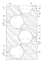
- FIG. 14 shows a photograph of the observation result of observing the foam with a microscope.
- FIG. 14A shows a foam according to a comparative example.
- FIG. 14B shows a foam according to an example.
- FIG. 14 (c) shows the foam according to the example in which the amount of antifoaming agent was increased as compared with FIG. 14 (b).
- These are images taken at a length of 5.4 mm and a width of 7.2 mm.
- a urethane raw material which is a molding resin for these foams, a material composed of an isocyanate-terminated prepolymer, several types of polyoxyethylene polyoxypropylene glycol having different molecular weights, and a polyol premix containing additives was adopted.
- the defoaming agent As the defoaming agent, a silicon-based defoaming agent "GC-302" manufactured by "Nisshin Kagaku Kenkyusho” was adopted.
- the amount of the defoaming agent introduced was 0.005% by mass.
- the amount of the defoaming agent introduced was 0.05% by mass.
- the amount of the defoaming agent introduced was 0.08% by mass.
- FIG. 14A the cell 42 was not sufficiently large enough to correspond to the large cell 42A, and the cell 42 capable of sufficiently functioning as the cavity 2 could not be confirmed.
- FIGS. 14 (b) and 14 (c) it can be confirmed that a sufficiently large large cell 42A capable of functioning as the cavity 2 has been obtained.
- FIG. 14B the combination of the Helmholtz-shaped cavity portion 2 and the neck portion 3 can be confirmed in the portion shown by “A”.
- FIGS. 14 (b) and 14 (c) show only one cross section, and a structure in which the cavity 2 and the neck 3 communicate with each other in a portion that cannot be confirmed in the photograph when viewed three-dimensionally. Exists.
- the molded foam 45 may be used as it is as a sound absorbing material, or a treatment for forming the neck portion 3 may be performed.
- a treatment for forming the neck portion 3 may be performed.
- laser irradiation, insertion of a needle-shaped member, blowing of gas, mixing of volatile components, and the like may be performed.
- FIG. 15A the needle-shaped member 46 is inserted into the molded foam 45.
- FIG. 15B by removing the needle-shaped member 46, a hole 47 is formed in the foam 45 at a position where the needle-shaped member 46 has been inserted.
- a processed portion 48 extending in the foam 45 is formed.
- a processed portion 48 communicating with the pair of cavity portions 2 (large cell 42A) is formed between the pair of cavity portions 2 (large cell 42A).
- the portion functions as a neck portion 3 by the processed portion 48.
- a processed portion 48 that communicates the cavity portion 2 (large cell 42A) with the surface is formed.
- Such a portion also functions as a neck portion 3 by the processed portion 48.
- FIG. 17A is an enlarged view of the neck portion 3 in the form shown in FIG. 3 and the neck portion 3 by the processed portion 48 in FIG.
- FIG. 17B is an enlarged view of the neck portion 3 by the small cell 42B in the form shown in FIG.
- FIG. 18 shows an enlarged view of the neck portion 3 of the molded product according to the comparative example.
- the communication member 100 is mixed in the molding material.
- the communication member 100 is a material different from the molding material, such as a fiber member, and remains in a state of maintaining the shape as a member (without disappearing like a defoamer) even after molding. Consists of materials.
- cells 42 are formed by foaming. Further, by arranging the communication member between the pair of cells 42, the pair of cells 42 are in a state of communicating with each other. As a result, the cell 42 functions as the cavity portion 2, and the communication member 100 functions as the neck portion 3.
- the cavity 2 is formed of a molding material, and the inner surface 2b of the cavity 2 is also formed of a molding material.
- the neck portion 3 is formed by the communication member 100, and the inner surface 3c of the neck portion 3 is also formed by the communication member 100 (inner surface of the communication member).
- a boundary surface BF is formed between the molding material forming the cavity 2 and the communicating member 100 forming the neck 3 in an observable manner. NS. This state does not correspond to a state in which the material forming the cavity 2 and the material forming the neck 3 are integrally formed. Even if the material of the communicating member 100 is the same or similar in composition to the molding material, the boundary surface BF is formed.
- the boundary surface BF remains. Even if it is difficult to visually observe the boundary surface BF, the hardness of the material on the neck portion 3 side and the material on the cavity portion 2 side are different, so that the boundary surface BF between the two can be confirmed. be. Therefore, regardless of the composition of the material of the communicating member 100, such a boundary surface BF is formed in an observable manner after molding.
- the inner surface 3c of the neck portion 3 is formed by the molding material itself.
- the molding material 50 (molding material existing around the space of the neck portion 3) forming the neck portion 3 is exposed as it is in the space of the neck portion 3.
- the cavity portion 2 and the neck portion 3 communicating with the cavity portion 2 are integrally formed of the same molding material. That is, the molding material 51 that forms the cavity 2 (the molding material that exists around the space of the cavity 2) and the molding material 50 that forms the neck 3 (the molding material that exists around the space of the neck 3).
- the boundary surface BF as shown in FIG. 19B does not exist between the and, and the molding material is in a continuous state.
- an auxiliary agent for forming the neck portion 3 may be used.
- capsules that melt due to heat during molding may be used.
- Such a member is a member included in the molding material because it is absorbed by the molding material by being melted by heat. The undissolved residue of such a member may remain on the inner surface 3c of the neck portion 3, but such undissolved residue is also a part of the molding material. Since the communication member 100 shown in FIG. 18 is not a member that is supposed to be melted by heat during molding, it cannot be regarded as a part of the molding material.
- the neck portion 3 has a shape in which the center line CL1 extends linearly.
- the communicating member 100 since the communicating member 100 is mixed with the molding resin in the flowing state for molding, the communicating member 100 is solidified in a randomly bent shape. Therefore, as shown in FIG. 18, the center line CL2 of the neck portion 3 is bent and does not extend linearly.
- the neck portion 3 having a hollow cylindrical shape (cylindrical hole shape) is illustrated, but the shape is not particularly limited as long as the linear center line CL1 can be set.
- the neck portion 3 has a hollow prism shape such as a hollow triangular pillar, a hollow square pillar, or a hollow pentagonal pillar; a hollow conical frustum shape; Even in such a case, the center line CL1 can be formed to have a linearly extended shape.
- the communication member constituting the neck portion 3 extends largely inside the cavity portion 2.
- the neck portion 3 does not extend inside the cavity portion 2.
- steps, protrusions, ridges, etc. referred to as protrusions 54
- the height can be suppressed to a minute level that does not significantly impair the sound absorption performance and the vibration absorption performance. ..
- the protrusion height H2 in the comparative example is larger than 100 ⁇ m, which is a range that affects the performance. More specifically, if the protruding height H2 in the comparative example is larger than 100 ⁇ m and about 1 mm is not secured, the molding resin will flow into the communicating member 100 and the opening will be closed with the molding resin. .. In this case, the state of being opened in the cavity 2 cannot be maintained, and the neck 3 cannot be formed in the first place.
- the protrusion height H1 of the protrusion 54 is suppressed to 100 ⁇ m or less, which is a range that does not affect the performance. More preferably, the protrusion height H1 is suppressed to 0 ⁇ m or more and 80 ⁇ m or less.
- the definitions of the heights H1 and H2 are not particularly limited, but they may be specified by using the cross section near the neck portion 3 as follows. First, pay attention to the vicinity of the opening of the neck portion 3 in the inner surface 2b of the cavity portion 2. When the projecting portion 54 is present, the base point SP that rises inward of the cavity portion 2 exists on the inner surface 2b of the cavity portion 2.
- the reference line SL is extended from the base point SP to the neck portion 3 side.
- the tangent CTL with respect to the contact CTP is orthogonal to the reference line SL.
- the dimension of the portion where the protruding portion 54 is highest with respect to the reference line SL is defined as the “height of the protruding portion”.
- the definition of the height of the protrusion 54 is not limited to this, and other known methods may be used.
- the case where the protruding portion 54 is not formed means that the base point SP as described above does not exist (substantially does not exist) on the inner surface 2b of the hollow portion 2 in the vicinity of the opening of the neck portion 3.
- each parameter refers to each embodiment of FIGS. 1 to 5 and 12 to 19.
- the diameter of the cavity 2 is 2000 ⁇ m or more and 9000 ⁇ m or less.
- the upper limit of the diameter of the cavity 2 may be 8000 ⁇ m, 7000 ⁇ m, or 6000 ⁇ m.
- the lower limit of the diameter of the cavity 2 may be 3000 ⁇ m, 4000 ⁇ m, or 5000 ⁇ m.
- the diameter of the cavity 2 is 5000 ⁇ m.
- the diameter of the cavity 2 is not limited to 5000 ⁇ m, and can be appropriately changed according to the target frequency and the like.
- the diameter can be determined by measuring the cavity 2 and the neck 3 from the observation image with a microscope.
- the cross section of the cavity portion 2 and the neck portion 3 shown in FIG. 16 and the like may not always be a perfect circle.
- the area of the cavity 2 that can be observed in the observation image is calculated.
- a circle corresponding to the area was virtually drawn, and the diameter of the circle was defined as the diameter of the cavity 2.
- the neck portion 3 is formed by a plurality of cells 42
- the total area of the plurality of cells 42 is calculated from the observation image, and the diameter of the circle corresponding to the area is the neck portion. It is defined as a diameter of 3.
- the method for determining the diameter of each cell is the same as the above method.
- the volume of the cavity 2 is 4.19 ⁇ 10 9 ⁇ m 3 or more and 3.82 ⁇ 10 11 ⁇ m 3 or less.
- the upper limit of the volume of the cavity 2 may be 2.68 ⁇ 10 11 ⁇ m 3 , 1.80 ⁇ 10 11 ⁇ m 3 , or 1.13 ⁇ 10 11 ⁇ m 3 .
- the lower limit of the volume of the cavity 2 may be 1.41 ⁇ 10 10 ⁇ m 3 , 3.35 ⁇ 10 10 ⁇ m 3 , or 6.54 ⁇ 10 10 ⁇ m 3 .
- the volume of the cavity 2 is 4.19 ⁇ 10 9 ⁇ m 3 or more and 381.51 ⁇ 10 9 ⁇ m 3 or less.
- the volume of the cavity 2 is not limited to the above example, and can be appropriately changed according to the target frequency and the like.
- the cavity 2 is formed by cells 42 that are 100% or more larger than the average diameter of the entire cell 42 among the cells 42 inside the foam, and are preferably formed by cells that are 300% or more and 2200% or more larger. ..
- the average diameter is calculated by "(total value of the diameters of all cells in a unit volume) / (number of all cells in a unit volume)".
- the cell 42 within a unit volume includes all of the cell 42 forming the cavity 2, the cell 42 forming the neck 3, and the cell 42 in which neither the cavity 2 nor the neck 3 is formed.
- the fine cells 42C that have been crushed to the extent that they cannot be counted may be collectively counted as one cell 42.
- the diameter of the neck portion 3 is 10 ⁇ m or more and 1000 ⁇ m or less.
- the upper limit of the diameter of the neck portion 3 may be 900 ⁇ m, 800 ⁇ m, or 700 ⁇ m.
- the lower limit of the diameter of the neck portion 3 may be 20 ⁇ m, 30 ⁇ m, or 40 ⁇ m.
- the diameter of the neck portion 3 is 10 ⁇ m or more and 500 ⁇ m or less.
- the diameter of the neck portion 3 is not limited to the above example, and can be appropriately changed according to the target frequency and the like.
- the number of neck portions 3 extending from one cavity portion 2 is, for example, 2 or more and 24 or less.
- the upper limit of the number of neck portions 3 extending from one cavity portion 2 may be, for example, 15 or 13.
- the lower limit of the number of neck portions 3 extending from one cavity portion 2 may be, for example, 3, 4, 5, 6, 8 or 10.
- the number of neck portions 3 is 12.
- the number of neck portions 3 extending from one cavity portion 2 is not limited to the above example and can be appropriately changed.
- openings 3b are formed on the inner surface 2b of the cavity 2 exposed on the surface 1b.
- the ratio of the number of neck portions 3 to the number of cavity portions 2 is, for example, 1 or more and 24 or less.
- the lower limit of the ratio may be 1.1, 3.0, 5.0, 7.0 or 11.0.
- the upper limit of the ratio may be 20.0, 16.0, 14.0 or 13.0.
- the ratio of the number of neck portions 3 to the number of cavity portions 2 can be appropriately changed.
- one neck portion 3 is formed by a set of a plurality of small cells 42B or fine cells 42C, it is counted as one neck portion 3. However, it is not necessary to count the ones that are so fine that they do not function as the neck portion 3.
- the air permeability of the molded product is, for example, 0.4 cm 3 / (cm 2 ⁇ s) or more and 200 cm 3 / (cm 2 ⁇ s) or less.
- the air permeability was measured using a Frazier type air permeability tester (manufactured by Textest, Switzerland) in accordance with JIS K 6400.
- the target frequency of the wavelength absorption unit 10 is, for example, 450 Hz or more and 10000 Hz or less. As an example, the target frequency of the wavelength absorption unit 10 may be 250 Hz or more and 2000 Hz or less, or 1000 Hz or less.
- the wavelength absorption rate of 450 Hz or more and 10000 Hz or less in the wavelength absorption unit 10 is 0.4 or more. For example, when sound wave energy of the target frequency is incident on the neck portion 3, the sound wave energy vibrates violently in the neck portion 3, and the air in the cavity portion 2 located at the back of the neck portion 3 functions as a spring to generate the sound wave energy. Sound is absorbed by viscous attenuation.
- the wavelength absorption rate indicates the rate at which a wavelength of a specific frequency is absorbed. A wavelength absorption rate of 1.00 means that the reflection of the incident wave is 0%, and a wavelength absorption rate of 0.00 means that the incident wave is 100% reflected.
- the target frequency of the vertically incident sound absorption coefficient of the molded product is the same as that mentioned in the above-mentioned wavelength absorption coefficient.
- the vertical incident sound absorption coefficient per 10 mm thickness of 450 Hz or more and 10000 Hz or less is preferably 0.4 or more, and preferably 0.6 or more.
- the above-mentioned vertical incident sound absorption coefficient is specified as a value per 10 mm of the molded product, the value of the product itself may be specified, or it may be specified as a value per unit thickness in a unit area.
- the above-mentioned parameters are substantially uniform over the entire area where the sound absorbing performance is exhibited in the molded body. Become.
- FIGS. 12 and 16 when the cavity 2 and the neck 3 are formed at random sizes and at random locations, each of the above parameters becomes random in each region of the molding body. In some cases. Therefore, the relationship between such a random configuration and the above-mentioned parameters will be described with reference to FIG.
- FIG. 20 when the unit volume is taken out from each position of the sound absorbing material (molded body), there is a parameter that satisfies the condition in the unit volume at each place.
- “size of cavity”, “size of neck”, “relationship between cavity and neck”, and “vertical incident sound absorption coefficient” correspond to such parameters.
- “vertical incident sound absorption coefficient” corresponds to such a parameter.
- the sound absorbing material (molded article) as a product as a whole satisfies the conditions.
- the above-mentioned “air permeability” and “vertical incident sound absorption coefficient” correspond to such parameters.
- FIG. 6 is an exemplary graph showing the relationship between the frequency of sound waves incident on a sound absorbing material having no cavity 2 and neck 3 and the vertical incident sound absorbing coefficient for each material of the sound absorbing material.
- FIG. 6 shows a case where each of semi-hard urethane, hard urethane, low-breathable soft urethane, and highly breathable soft urethane is used as the material of the sound absorbing material.
- the vertically incident sound absorption coefficient indicates the absorption rate of the sound wave when the sound wave is applied in the direction perpendicular to the surface of the sound absorbing material.
- the vertical incident sound absorption coefficient was measured using a 4206 type acoustic tube (manufactured by Spectris) and using the vertical incident sound absorption coefficient measurement software MS1021 (manufactured by Spectris) in accordance with JIS A 1405 with a back air layer of 0 mm.
- FIG. 6 it can be seen that the vertical incident sound absorption coefficient does not change much (for example, less than 0.6) when the frequency is 2000 Hz or less even if the hardness and viscoelasticity of the sound absorbing material change.
- the vertically incident sound absorption coefficient indicates the rate at which sound waves of a specific frequency incident vertically are absorbed.
- a wavelength absorption rate of 1.00 means that the reflection of the incident wave is 0%, and a wavelength absorption rate of 0.00 means that the incident wave is 100% reflected.
- FIG. 7 is an exemplary graph showing the relationship between the frequency of sound waves incident on a 10 mm thick molded body 1 having a cavity 2 and a neck 3 and a vertically incident sound absorption coefficient for each diameter of the neck 3.
- FIG. 7 shows a case where the diameter of the cavity portion 2 is 5000 ⁇ m and the diameter of the neck portion 3 is 50 ⁇ m, 100 ⁇ m, 200 ⁇ m, and 400 ⁇ m, respectively.
- FIG. 8 is an exemplary graph showing the relationship between the diameter of the neck portion 3 and the peak value of the frequency having the highest sound absorption coefficient when the thickness of the molded body 1 is 10 mm and the diameter of the cavity portion 2 is 5000 ⁇ m. be.
- the frequency is around 1000 Hz. It was found that it can absorb sound waves of the same frequency.
- the diameter of the neck portion 3 it was possible to absorb sound waves having a frequency corresponding to the calculated value of the above-mentioned equation (1). That is, it was found that sound waves of a wide range of target frequencies can be absorbed by changing the diameter of the neck portion 3.
- the molded body 1 has an open cell property, it can absorb sound waves in a wavelength region around a target frequency satisfactorily.
- FIG. 8 shows the measured value and the calculated value when the thickness of the molded body 1 is 10 mm, and it is found that the measured value exceeds the calculated value when the thickness of the molded body 1 is 10 mm. rice field. However, when the thickness of the molded body 1 is 15 mm, it is known that the measured value and the calculated value substantially match.
- FIG. 9 is an exemplary graph showing the relationship between the frequency of sound waves incident on the molded body 1 having the cavity 2 and the neck 3 and the vertical incident sound absorption coefficient for each diameter of the cavity 2.
- FIG. 9 shows a case where the diameter of the neck portion 3 is 400 ⁇ m and the diameter of the cavity portion 2 is 5000 ⁇ m, 6000 ⁇ m, and 7000 ⁇ m, respectively. As shown in FIG. 9, it was found that even if the diameter of the cavity 2 changes in the range of 5000 ⁇ m or more and 7,000 ⁇ m or less, the vertical incident sound absorption coefficient does not change as much as when the diameter of the neck portion 3 changes.
- FIG. 10 is a graph showing the relationship between the frequency of sound waves incident on the molded body 1 having the cavity portion 2 and the neck portion 3 and the vertical incident sound absorption coefficient for each material of the molded body 1.
- a 3D printer device manufactured by 3D Systems, product name: Project MJP 5500X
- # 100, # 250 or # 400 all model numbers
- the model number "# 100" is that when the molded body 1 is made of acrylonitrile-butadiene-styrene resin (ABS: Acrylonitrile Butadinee Styrene) resin, the model number "# 250” and the model number "# 400" are the molded body 1.
- a plurality of cavities 2 are formed inside, and a neck portion 3 is formed in each of the plurality of cavities 2.
- a part of the plurality of neck portions 3 communicates with the surface 1b and / or the cavity portion 2 exposed on the surface 1b.
- At least a part of the plurality of neck portions 3 communicates the plurality of cavity portions 2 with each other. Therefore, when vibration energy including sound waves is incident on the neck portion 3, violent vibration is generated, and the cavity portion 2 on the opposite side (back side) of the surface 1b functions as a spring, so that the vibration energy is viscously attenuated. Therefore, high sound absorption performance and vibration absorption performance can be exhibited by the neck portion 3 and the cavity portion 2 that expands on the opposite side of the surface 1b of the neck portion 3.
- the inner surface 3c of the neck portion 3 is formed by the molding material itself.
- the incident of vibration energy into the cavity 2 and the neck 3 can be made smoother than in the case where the neck 3 is formed of a separate dedicated member (such as the communication member 100 in FIG. 18). can. Therefore, the sound absorption performance and the vibration absorption performance can be improved without increasing the size of the molded body. As a result, it is possible to suppress an increase in the size of the molded product.
- the molded body is a foam, and the cavity 2 may be formed by the cells 42 inside the foam, which are 100% or more larger than the average diameter of the entire cells 42.
- At least a part of the neck portion 3 may be formed by cells 42 inside the foam.
- At least a part of the neck portion 3 may have a shape in which the center line CL1 extends linearly.
- the neck portion 3 extends from the inner surface 2b that defines the cavity portion 2 to the inner surface 2b of another cavity portion 2 adjacent to the cavity portion 2. Therefore, since the neck portion 3 can be formed so as not to protrude from the inner surface 2b that defines the cavity portion 2, the incident of vibration energy into the cavity portion 2 and the neck portion 3 can be made smoother. Therefore, in the molded body 1, the sound absorption performance and the vibration absorption performance can be improved without increasing the size. As a result, it is possible to suppress an increase in the size of the molded body 1.
- the protruding height of the protruding portion 54 with respect to the inner surface 2b of the cavity portion 2 is 100 ⁇ m or less. good. In this case, the incident of vibration energy into the cavity 2 and the neck 3 can be made smoother.
- the material of the cavity 2 and the material of the neck 3 may be the same as each other. In this case, since the molded body 1 can be manufactured with a single material, the molded body 1 can be easily manufactured.
- the molded body is a foam, and the cavity 2 may be formed by the cells 42 inside the foam, which are 100% or more larger than the average diameter of the entire cells 42. In this case, the large cell 42 can form a cavity 2 having a sufficient size.
- At least a part of the neck portion 3 may be formed by cells 42 inside the foam.
- the neck portion 3 can be easily formed without using a dedicated member or the like for providing the neck portion 3.
- At least a part of the neck portion 3 may have a shape in which the center line CL1 extends linearly. In this case, the vibration energy can be smoothly incident on the neck portion 3.
- the ratio of the number of neck portions 3 to the number of cavity portions 2 may be 1.1 or more. In this case, by increasing the ratio of the number of the neck portions 3, the frictional action between the vibration including the sound waves and the neck portions 3 can be strengthened, so that the sound wave energy and the vibration energy can be absorbed more efficiently. ..
- the plurality of cavity portions 2 and the plurality of neck portions 3 may form a wavelength absorption unit 10, and the wavelength absorption rate of 450 Hz or more and 10,000 Hz or less in the wavelength absorption unit 10 may be 0.4 or more.
- the sound wave energy and vibration energy in the frequency band of 450 Hz or higher and 10000 Hz or lower can be absorbed with higher efficiency.
- the vertical incident sound absorption coefficient per 10 mm thickness of 450 Hz or more and 10000 Hz or less may be 0.4 or more.
- the sound wave energy and vibration energy in the frequency band of 450 Hz or higher and 10000 Hz or lower can be absorbed with higher efficiency.
- the diameter of the neck portion 3 may be 10 ⁇ m or more and 1000 ⁇ m or less. In this case, the sound wave energy and the vibration energy in the target frequency band can be absorbed more efficiently.
- the volume of the cavity 2 may be 4.19 ⁇ 10 9 ⁇ m 3 or more and 3.82 ⁇ 10 11 ⁇ m 3 or less. In this case, the sound wave energy and the vibration energy in the target frequency band can be absorbed more efficiently.
- Mold 1 may contain urethane foam at least in part. In this case, it is possible to provide the molded product 1 having high flexibility.
- the molded body 1 may contain at least one of a thermoplastic resin and a photocurable resin. In this case, since the molded body 1 can be manufactured by a 3D printer or the like, the molded body 1 can be manufactured more easily.
- the air permeability may be 0.4 cm 3 / (cm 2 ⁇ s) or more and 200 cm 3 / (cm 2 ⁇ s) or less. In this case, the sound absorption performance and the vibration absorption performance can be enhanced, and the desired air permeability can be ensured.
- the shape of the molded product can be changed as appropriate.
- the molded product according to the present disclosure may be a rectangular plate-shaped molded product 21.
- the molded body 21 has, for example, a main surface 22 on which sound waves or vibrations are incident, one or more (four as an example) side surfaces 23 facing in different directions from the main surface 22, and a back surface facing the opposite side of the main surface 22. It has 24 and.
- the molded body 21 includes a main surface 22, a back surface 24 provided facing the main surface 22, and a side surface 23 provided between the main surface 22 and the back surface 24.
- a part of the plurality of neck portions 3 may be exposed on the main surface 22 or the above-mentioned cavity 2 exposed on the main surface 22.
- the thickness T1 of the molded body 21 is, for example, 5 mm or more and 10 mm or less.
- the upper limit of the thickness T1 may be a value other than 10 mm
- the lower limit of the thickness T1 may be a value other than 5 mm.
- the molded body 21 can more effectively absorb sound waves or vibrations.
- sound waves or vibrations can be effectively absorbed even if the thickness T1 is 10 mm or less.
- the thickness T1 is 10 mm or less, the size of the molded body 21 can be made more compact.
- the molded article according to the present disclosure includes a main surface 32 on which sound waves or vibrations are incident, a side surface 33 facing a direction different from the main surface 32, and an opposite side of the main surface 32. It may be a disk-shaped molded body 31 having a back surface 34 facing the surface.
- the thickness T2 of the molded body 31 can be, for example, the same as the thickness T1 of the molded body 21 described above. As described above, the shape and size of the molded product according to the present disclosure can be changed as appropriate.
- the sound absorbing material according to this embodiment may be the molded body 1 described above. Further, the vibration absorbing material according to the present embodiment may be the molded body 1. In this case, it is possible to provide a sound absorbing material or a vibration absorbing material having the same effect as described above.
- the present disclosure is not limited to the embodiments described above.
- the present disclosure can be modified in various ways without changing the gist described in the claims. That is, the shape, size, number, material, function, and arrangement mode of each part of the molded body, the sound absorbing material, and the vibration absorbing material can be appropriately changed without changing the above gist.
Landscapes
- Physics & Mathematics (AREA)
- Acoustics & Sound (AREA)
- Engineering & Computer Science (AREA)
- Architecture (AREA)
- Multimedia (AREA)
- Electromagnetism (AREA)
- Civil Engineering (AREA)
- Structural Engineering (AREA)
- Moulds For Moulding Plastics Or The Like (AREA)
- Soundproofing, Sound Blocking, And Sound Damping (AREA)
- Blow-Moulding Or Thermoforming Of Plastics Or The Like (AREA)
Priority Applications (5)
| Application Number | Priority Date | Filing Date | Title |
|---|---|---|---|
| US17/915,445 US12227938B2 (en) | 2020-03-30 | 2021-03-29 | Molded body, sound absorbing material, vibration absorbing material |
| KR1020227036548A KR102904393B1 (ko) | 2020-03-30 | 2021-03-29 | 성형체, 흡음재, 및 진동 흡수재 |
| JP2022512244A JP7687335B2 (ja) | 2020-03-30 | 2021-03-29 | 成形体、吸音材、及び振動吸収材 |
| CN202180025249.6A CN115362495B (zh) | 2020-03-30 | 2021-03-29 | 成形体、吸音材料以及振动吸收材料 |
| EP21779746.3A EP4108845B1 (en) | 2020-03-30 | 2021-03-29 | Molded body, sound absorbing material, vibration absorbing material |
Applications Claiming Priority (2)
| Application Number | Priority Date | Filing Date | Title |
|---|---|---|---|
| JP2020061081 | 2020-03-30 | ||
| JP2020-061081 | 2020-03-30 |
Publications (1)
| Publication Number | Publication Date |
|---|---|
| WO2021200870A1 true WO2021200870A1 (ja) | 2021-10-07 |
Family
ID=77930084
Family Applications (1)
| Application Number | Title | Priority Date | Filing Date |
|---|---|---|---|
| PCT/JP2021/013396 Ceased WO2021200870A1 (ja) | 2020-03-30 | 2021-03-29 | 成形体、吸音材、及び振動吸収材 |
Country Status (6)
| Country | Link |
|---|---|
| US (1) | US12227938B2 (https=) |
| EP (1) | EP4108845B1 (https=) |
| JP (1) | JP7687335B2 (https=) |
| KR (1) | KR102904393B1 (https=) |
| CN (1) | CN115362495B (https=) |
| WO (1) | WO2021200870A1 (https=) |
Families Citing this family (1)
| Publication number | Priority date | Publication date | Assignee | Title |
|---|---|---|---|---|
| KR102827298B1 (ko) * | 2023-05-04 | 2025-06-27 | 부산대학교 산학협력단 | 멤브레인과 국소공진체를 구비하는 차음 장치 |
Citations (2)
| Publication number | Priority date | Publication date | Assignee | Title |
|---|---|---|---|---|
| JPH09114468A (ja) * | 1995-10-24 | 1997-05-02 | Matsushita Electric Works Ltd | 粉体含有シート状物及び粉体含有シート状物を用いた吸音材 |
| JP2008096637A (ja) | 2006-10-11 | 2008-04-24 | Sekisui Chem Co Ltd | 吸音材 |
Family Cites Families (11)
| Publication number | Priority date | Publication date | Assignee | Title |
|---|---|---|---|---|
| US4562901A (en) | 1983-10-12 | 1986-01-07 | Miguel C. Junger | Sound absorptive structural block with sequenced cavities |
| JP2850447B2 (ja) * | 1990-02-23 | 1999-01-27 | 松下電工株式会社 | 遮音パネル |
| US5981046A (en) * | 1995-03-13 | 1999-11-09 | Sumitomo Chemical Company, Limited | Sound absorbing component |
| JPH10121598A (ja) * | 1996-10-16 | 1998-05-12 | Matsushita Electric Works Ltd | 吸音材およびその製造方法 |
| JP2001041020A (ja) * | 1999-07-27 | 2001-02-13 | Nok Vibracoustic Kk | 吸音材 |
| JP2001335383A (ja) * | 2000-05-25 | 2001-12-04 | Toyota Motor Corp | 吸音材とその製造方法、および発泡造粒体とその製造方法 |
| JP3934034B2 (ja) * | 2002-11-11 | 2007-06-20 | ダイセル化学工業株式会社 | 吸音性成形体 |
| JP2008299201A (ja) * | 2007-06-01 | 2008-12-11 | Sekisui Chem Co Ltd | 吸音材 |
| BR112013000807A2 (pt) * | 2010-07-15 | 2016-05-24 | Aishin Kako Kk | estrutura tendo uma característica de absorção de som |
| JP6341659B2 (ja) * | 2013-12-19 | 2018-06-13 | キヤノン株式会社 | 樹脂性外装カバーおよびその製造方法 |
| KR101816007B1 (ko) * | 2016-01-13 | 2018-01-09 | 경북대학교 산학협력단 | 초음파의 흡수가 가능한 헬름홀츠 공명홀을 가지는 흡음재 제작방법 및 그 방법으로 제작된 흡읍재 |
-
2021
- 2021-03-29 JP JP2022512244A patent/JP7687335B2/ja active Active
- 2021-03-29 KR KR1020227036548A patent/KR102904393B1/ko active Active
- 2021-03-29 WO PCT/JP2021/013396 patent/WO2021200870A1/ja not_active Ceased
- 2021-03-29 CN CN202180025249.6A patent/CN115362495B/zh active Active
- 2021-03-29 US US17/915,445 patent/US12227938B2/en active Active
- 2021-03-29 EP EP21779746.3A patent/EP4108845B1/en active Active
Patent Citations (2)
| Publication number | Priority date | Publication date | Assignee | Title |
|---|---|---|---|---|
| JPH09114468A (ja) * | 1995-10-24 | 1997-05-02 | Matsushita Electric Works Ltd | 粉体含有シート状物及び粉体含有シート状物を用いた吸音材 |
| JP2008096637A (ja) | 2006-10-11 | 2008-04-24 | Sekisui Chem Co Ltd | 吸音材 |
Non-Patent Citations (1)
| Title |
|---|
| See also references of EP4108845A4 |
Also Published As
| Publication number | Publication date |
|---|---|
| US20230040730A1 (en) | 2023-02-09 |
| JP7687335B2 (ja) | 2025-06-03 |
| KR102904393B1 (ko) | 2025-12-24 |
| EP4108845A1 (en) | 2022-12-28 |
| CN115362495A (zh) | 2022-11-18 |
| EP4108845A4 (en) | 2024-03-06 |
| EP4108845B1 (en) | 2026-01-21 |
| KR20220154815A (ko) | 2022-11-22 |
| CN115362495B (zh) | 2025-12-23 |
| US12227938B2 (en) | 2025-02-18 |
| JPWO2021200870A1 (https=) | 2021-10-07 |
Similar Documents
| Publication | Publication Date | Title |
|---|---|---|
| US10352210B2 (en) | Acoustic device | |
| US11097828B2 (en) | Shroud | |
| WO2003001501A1 (en) | Porous soundproof structural body and method of manufacturing the structural body | |
| JP2019522151A (ja) | 慣性増幅機構を有するフォノニック結晶防振体 | |
| WO2021200870A1 (ja) | 成形体、吸音材、及び振動吸収材 | |
| JP4167673B2 (ja) | 膜状吸音構造 | |
| EP4182918B1 (en) | Noise barrier and apparatus comprising the noise barrier | |
| US11475871B2 (en) | Device for reducing noise using sound meta-material | |
| US11986849B2 (en) | Air amplifier with noise suppression | |
| CN112119452B (zh) | 隔音元件 | |
| JPH10273938A (ja) | 吸音部材 | |
| JP2894143B2 (ja) | 遮音板及び車両の遮音構造 | |
| JP2019006853A (ja) | 防音シート、及びその製造方法 | |
| JP2008299201A (ja) | 吸音材 | |
| US20190358871A1 (en) | Method of producing vibration damping and sound absorbing foam | |
| US20240183293A1 (en) | Air amplifier with noise suppression | |
| CN117980137A (zh) | 吸音封围件(h)以及用于制造吸音封围件(h)的方法 | |
| WO2020003593A1 (ja) | 吸音材 | |
| JP2018158691A (ja) | 車両用吸音材、車両用部品、自動車及び自動車用仕切り部材 | |
| WO2025174416A1 (en) | Air amplifier with multi-stage noise suppression system | |
| KR101437225B1 (ko) | 타공 박막 흡음셀 | |
| JP5906573B2 (ja) | ダクト | |
| JP2025070275A (ja) | 制振シート及び制振シートの製造方法 | |
| CN114127459A (zh) | 吸音装置 | |
| JP2008069523A (ja) | 吸音パネル |
Legal Events
| Date | Code | Title | Description |
|---|---|---|---|
| 121 | Ep: the epo has been informed by wipo that ep was designated in this application |
Ref document number: 21779746 Country of ref document: EP Kind code of ref document: A1 |
|
| ENP | Entry into the national phase |
Ref document number: 2022512244 Country of ref document: JP Kind code of ref document: A |
|
| ENP | Entry into the national phase |
Ref document number: 2021779746 Country of ref document: EP Effective date: 20220921 |
|
| ENP | Entry into the national phase |
Ref document number: 20227036548 Country of ref document: KR Kind code of ref document: A |
|
| NENP | Non-entry into the national phase |
Ref country code: DE |
|
| WWG | Wipo information: grant in national office |
Ref document number: 2021779746 Country of ref document: EP |