WO2021200652A1 - 直線偏光反射フィルム、ウインドシールドガラスおよびヘッドアップディスプレイシステム - Google Patents
直線偏光反射フィルム、ウインドシールドガラスおよびヘッドアップディスプレイシステム Download PDFInfo
- Publication number
- WO2021200652A1 WO2021200652A1 PCT/JP2021/012859 JP2021012859W WO2021200652A1 WO 2021200652 A1 WO2021200652 A1 WO 2021200652A1 JP 2021012859 W JP2021012859 W JP 2021012859W WO 2021200652 A1 WO2021200652 A1 WO 2021200652A1
- Authority
- WO
- WIPO (PCT)
- Prior art keywords
- reflection
- linearly polarized
- light
- polarized light
- reflection peak
- Prior art date
- Legal status (The legal status is an assumption and is not a legal conclusion. Google has not performed a legal analysis and makes no representation as to the accuracy of the status listed.)
- Ceased
Links
Images


Classifications
-
- B—PERFORMING OPERATIONS; TRANSPORTING
- B60—VEHICLES IN GENERAL
- B60K—ARRANGEMENT OR MOUNTING OF PROPULSION UNITS OR OF TRANSMISSIONS IN VEHICLES; ARRANGEMENT OR MOUNTING OF PLURAL DIVERSE PRIME-MOVERS IN VEHICLES; AUXILIARY DRIVES FOR VEHICLES; INSTRUMENTATION OR DASHBOARDS FOR VEHICLES; ARRANGEMENTS IN CONNECTION WITH COOLING, AIR INTAKE, GAS EXHAUST OR FUEL SUPPLY OF PROPULSION UNITS IN VEHICLES
- B60K35/00—Instruments specially adapted for vehicles; Arrangement of instruments in or on vehicles
- B60K35/20—Output arrangements, i.e. from vehicle to user, associated with vehicle functions or specially adapted therefor
- B60K35/21—Output arrangements, i.e. from vehicle to user, associated with vehicle functions or specially adapted therefor using visual output, e.g. blinking lights or matrix displays
- B60K35/23—Head-up displays [HUD]
-
- G—PHYSICS
- G02—OPTICS
- G02B—OPTICAL ELEMENTS, SYSTEMS OR APPARATUS
- G02B27/00—Optical systems or apparatus not provided for by any of the groups G02B1/00 - G02B26/00, G02B30/00
- G02B27/01—Head-up displays
- G02B27/0101—Head-up displays characterised by optical features
-
- G—PHYSICS
- G02—OPTICS
- G02B—OPTICAL ELEMENTS, SYSTEMS OR APPARATUS
- G02B5/00—Optical elements other than lenses
- G02B5/30—Polarising elements
- G02B5/3025—Polarisers, i.e. arrangements capable of producing a definite output polarisation state from an unpolarised input state
- G02B5/3033—Polarisers, i.e. arrangements capable of producing a definite output polarisation state from an unpolarised input state in the form of a thin sheet or foil, e.g. Polaroid
- G02B5/3041—Polarisers, i.e. arrangements capable of producing a definite output polarisation state from an unpolarised input state in the form of a thin sheet or foil, e.g. Polaroid comprising multiple thin layers, e.g. multilayer stacks
-
- G—PHYSICS
- G02—OPTICS
- G02B—OPTICAL ELEMENTS, SYSTEMS OR APPARATUS
- G02B5/00—Optical elements other than lenses
- G02B5/30—Polarising elements
- G02B5/3025—Polarisers, i.e. arrangements capable of producing a definite output polarisation state from an unpolarised input state
- G02B5/3066—Polarisers, i.e. arrangements capable of producing a definite output polarisation state from an unpolarised input state involving the reflection of light at a particular angle of incidence, e.g. Brewster's angle
-
- G—PHYSICS
- G02—OPTICS
- G02B—OPTICAL ELEMENTS, SYSTEMS OR APPARATUS
- G02B5/00—Optical elements other than lenses
- G02B5/30—Polarising elements
- G02B5/3083—Birefringent or phase retarding elements
-
- B—PERFORMING OPERATIONS; TRANSPORTING
- B60—VEHICLES IN GENERAL
- B60K—ARRANGEMENT OR MOUNTING OF PROPULSION UNITS OR OF TRANSMISSIONS IN VEHICLES; ARRANGEMENT OR MOUNTING OF PLURAL DIVERSE PRIME-MOVERS IN VEHICLES; AUXILIARY DRIVES FOR VEHICLES; INSTRUMENTATION OR DASHBOARDS FOR VEHICLES; ARRANGEMENTS IN CONNECTION WITH COOLING, AIR INTAKE, GAS EXHAUST OR FUEL SUPPLY OF PROPULSION UNITS IN VEHICLES
- B60K2360/00—Indexing scheme associated with groups B60K35/00 or B60K37/00 relating to details of instruments or dashboards
- B60K2360/20—Optical features of instruments
- B60K2360/23—Optical features of instruments using reflectors
-
- B—PERFORMING OPERATIONS; TRANSPORTING
- B60—VEHICLES IN GENERAL
- B60K—ARRANGEMENT OR MOUNTING OF PROPULSION UNITS OR OF TRANSMISSIONS IN VEHICLES; ARRANGEMENT OR MOUNTING OF PLURAL DIVERSE PRIME-MOVERS IN VEHICLES; AUXILIARY DRIVES FOR VEHICLES; INSTRUMENTATION OR DASHBOARDS FOR VEHICLES; ARRANGEMENTS IN CONNECTION WITH COOLING, AIR INTAKE, GAS EXHAUST OR FUEL SUPPLY OF PROPULSION UNITS IN VEHICLES
- B60K2360/00—Indexing scheme associated with groups B60K35/00 or B60K37/00 relating to details of instruments or dashboards
- B60K2360/20—Optical features of instruments
- B60K2360/25—Optical features of instruments using filters
-
- B—PERFORMING OPERATIONS; TRANSPORTING
- B60—VEHICLES IN GENERAL
- B60K—ARRANGEMENT OR MOUNTING OF PROPULSION UNITS OR OF TRANSMISSIONS IN VEHICLES; ARRANGEMENT OR MOUNTING OF PLURAL DIVERSE PRIME-MOVERS IN VEHICLES; AUXILIARY DRIVES FOR VEHICLES; INSTRUMENTATION OR DASHBOARDS FOR VEHICLES; ARRANGEMENTS IN CONNECTION WITH COOLING, AIR INTAKE, GAS EXHAUST OR FUEL SUPPLY OF PROPULSION UNITS IN VEHICLES
- B60K2360/00—Indexing scheme associated with groups B60K35/00 or B60K37/00 relating to details of instruments or dashboards
- B60K2360/60—Structural details of dashboards or instruments
- B60K2360/66—Projection screens or combiners
-
- B—PERFORMING OPERATIONS; TRANSPORTING
- B60—VEHICLES IN GENERAL
- B60K—ARRANGEMENT OR MOUNTING OF PROPULSION UNITS OR OF TRANSMISSIONS IN VEHICLES; ARRANGEMENT OR MOUNTING OF PLURAL DIVERSE PRIME-MOVERS IN VEHICLES; AUXILIARY DRIVES FOR VEHICLES; INSTRUMENTATION OR DASHBOARDS FOR VEHICLES; ARRANGEMENTS IN CONNECTION WITH COOLING, AIR INTAKE, GAS EXHAUST OR FUEL SUPPLY OF PROPULSION UNITS IN VEHICLES
- B60K35/00—Instruments specially adapted for vehicles; Arrangement of instruments in or on vehicles
- B60K35/20—Output arrangements, i.e. from vehicle to user, associated with vehicle functions or specially adapted therefor
- B60K35/21—Output arrangements, i.e. from vehicle to user, associated with vehicle functions or specially adapted therefor using visual output, e.g. blinking lights or matrix displays
- B60K35/23—Head-up displays [HUD]
- B60K35/233—Head-up displays [HUD] controlling the size or position in display areas of virtual images depending on the condition of the vehicle or the driver
-
- B—PERFORMING OPERATIONS; TRANSPORTING
- B60—VEHICLES IN GENERAL
- B60K—ARRANGEMENT OR MOUNTING OF PROPULSION UNITS OR OF TRANSMISSIONS IN VEHICLES; ARRANGEMENT OR MOUNTING OF PLURAL DIVERSE PRIME-MOVERS IN VEHICLES; AUXILIARY DRIVES FOR VEHICLES; INSTRUMENTATION OR DASHBOARDS FOR VEHICLES; ARRANGEMENTS IN CONNECTION WITH COOLING, AIR INTAKE, GAS EXHAUST OR FUEL SUPPLY OF PROPULSION UNITS IN VEHICLES
- B60K35/00—Instruments specially adapted for vehicles; Arrangement of instruments in or on vehicles
- B60K35/20—Output arrangements, i.e. from vehicle to user, associated with vehicle functions or specially adapted therefor
- B60K35/28—Output arrangements, i.e. from vehicle to user, associated with vehicle functions or specially adapted therefor characterised by the type of the output information, e.g. video entertainment or vehicle dynamics information; characterised by the purpose of the output information, e.g. for attracting the attention of the driver
-
- B—PERFORMING OPERATIONS; TRANSPORTING
- B60—VEHICLES IN GENERAL
- B60K—ARRANGEMENT OR MOUNTING OF PROPULSION UNITS OR OF TRANSMISSIONS IN VEHICLES; ARRANGEMENT OR MOUNTING OF PLURAL DIVERSE PRIME-MOVERS IN VEHICLES; AUXILIARY DRIVES FOR VEHICLES; INSTRUMENTATION OR DASHBOARDS FOR VEHICLES; ARRANGEMENTS IN CONNECTION WITH COOLING, AIR INTAKE, GAS EXHAUST OR FUEL SUPPLY OF PROPULSION UNITS IN VEHICLES
- B60K35/00—Instruments specially adapted for vehicles; Arrangement of instruments in or on vehicles
- B60K35/60—Instruments characterised by their location or relative disposition in or on vehicles
-
- G—PHYSICS
- G02—OPTICS
- G02B—OPTICAL ELEMENTS, SYSTEMS OR APPARATUS
- G02B27/00—Optical systems or apparatus not provided for by any of the groups G02B1/00 - G02B26/00, G02B30/00
- G02B27/01—Head-up displays
- G02B27/0101—Head-up displays characterised by optical features
- G02B2027/0118—Head-up displays characterised by optical features comprising devices for improving the contrast of the display / brillance control visibility
-
- G—PHYSICS
- G02—OPTICS
- G02B—OPTICAL ELEMENTS, SYSTEMS OR APPARATUS
- G02B27/00—Optical systems or apparatus not provided for by any of the groups G02B1/00 - G02B26/00, G02B30/00
- G02B27/01—Head-up displays
- G02B27/0101—Head-up displays characterised by optical features
- G02B2027/0145—Head-up displays characterised by optical features creating an intermediate image
Definitions
- the present invention relates to a linearly polarized reflective film that can be used as a combiner of a head-up display system, and a windshield glass and a head-up display system having this linearly polarized reflective film.
- head-up display or head-up display system that projects an image on the windshield glass of a vehicle or the like and provides the driver or the like with various information such as a map, a running speed, and the state of the vehicle.
- various information such as a map, a running speed, and the state of the vehicle.
- a virtual image of an image including the above-mentioned various information projected on the windshield glass is observed by a driver or the like.
- the image formation position of the virtual image is located on the front side outside the vehicle from the windshield glass.
- the image formation position of the virtual image is usually 1000 mm or more on the front side of the windshield glass, and is located on the outside world side of the windshield glass.
- the driver can obtain the above-mentioned various information while looking at the outside world in front of the driver without moving his / her line of sight significantly. Therefore, when the head-up display system is used, it is expected to drive more safely while obtaining various information.
- the head-up display system can be configured by forming a linearly polarized light reflective film on the windshield glass using a half mirror film.
- Various half mirror films that can be used in head-up display systems have been proposed.
- Patent Document 1 describes a light reflecting layer PRL-1 having a central reflection wavelength of 400 nm or more and less than 500 nm and a reflectance of 5% or more and 25% or less with respect to normal light at the central reflection wavelength, and central reflection of 500 nm or more and less than 600 nm.
- the light reflective layer PRL-2 which has a wavelength and has a reflectance of 5% or more and 25% or less for normal light at the central reflection wavelength, and the reflectance for normal light at a central reflection wavelength of 600 nm or more and less than 700 nm.
- the light-reflecting layers PRL-3 having a value of 5% or more and 25% or less, at least two or more light-reflecting layers containing one or more light-reflecting layers and having different central reflection wavelengths are laminated and laminated.
- a light-reflecting film is described in which at least two or more light-reflecting layers all reflect polarized light in the same direction.
- the light-reflecting film described in Patent Document 1 is incorporated in, for example, windshield glass to form a head-up display system.
- the windshield glass (combiner) that constitutes the head-up display system is required to have high visible light transmittance and to be able to visually recognize the image even when the driver wears polarized sunglasses.
- polarized sunglasses have a function of cutting s-polarized light. Therefore, by wearing polarized sunglasses, the glare of reflected light due to the hood of an oncoming vehicle or a puddle, which hinders driving, disappears.
- the light-reflecting film described in Patent Document 1 reflects p-polarized light in order to display a projected image with p-polarized light. Therefore, the image of the head-up display system can be visually recognized even when wearing polarized sunglasses that cut s-polarized light.
- the in-vehicle head-up display system is required to have a transparent appearance color even when viewed from various angles from the viewpoint of transmittance and design that exceed the legal regulations.
- it has been considered to reduce the reflectance in order to maintain the transmittance of 70% or more in the regulations and make the appearance color close to transparent.
- the reflectance is lowered too much, the brightness of the displayed image (projected image) is lowered and the visibility is deteriorated.
- An object of the present invention is a linearly polarized light reflecting film having high visible light transmittance, high brightness of a displayed image, and good transparency of appearance color, windshield glass using this linearly polarized light reflecting film, and head-up. To provide a display system.
- the selective reflective layer is (I) It has at least one first reflection peak having a central reflection wavelength of 430 nm or more and less than 500 nm, and the natural light reflectance at the first reflection peak is 10% or more and 20% or less. (Ii) The central reflection wavelength is 530 nm. It has at least one second reflection peak of 600 nm or more and less than 600 nm, and the natural light reflectance at the second reflection peak is 10% or more and 20% or less. (Iii) A third reflection having a central reflection wavelength of 600 nm or more and 800 nm or less.
- the third reflection peak satisfies any of the following (a) It has two or more reflection peaks and the natural light reflectance is 10% or more and 20% or less (b) One reflection peak The natural light reflectance is 10% or more and 20% or less, and the wavelength bandwidth of the region where the reflectance is higher than the average value of the maximum value and the minimum value of the reflectance of 600 nm to 800 nm is 120 nm or more. A linearly polarized reflective film that satisfies. [2] The intensity ratio of the first reflection peak to the second reflection peak is 80% or more and 120% or less. The intensity ratio of the first reflection peak to the third reflection peak is 80% or more and 120% or less.
- the wavelength bandwidth of the region where the reflectance is higher than the average value of the maximum value and the minimum value of the reflectance at 430 nm to 500 nm of the first reflection peak is 20 nm or more and 95 nm or less.
- the straight line according to [1] or [2], wherein the wavelength bandwidth of the region where the reflectance is higher than the average value of the maximum value and the minimum value of the reflectance of the second reflection peak at 530 nm to 600 nm is 20 nm or more and 95 nm or less.
- Polarized reflective film is 20 nm or more and 95 nm or less.
- the selective reflection layer is composed of two or more light reflection layers.
- the linearly polarized light-reflecting film according to any one of [1] to [3], wherein the light-reflecting layers having any of a first reflection peak, a second reflection peak, and a third reflection peak are in contact with each other.
- Linear refractive index film is 0.03 to 0.2.
- light means visible light and natural light (unpolarized light) unless otherwise specified.
- Visible light is light having a wavelength that can be seen by the human eye among electromagnetic waves, and usually indicates light in the wavelength range of 380 to 780 nm.
- Invisible light is light in a wavelength region of less than 380 nm or in a wavelength region of more than 780 nm.
- B blue
- G green
- R red
- the "visible light transmittance” is the A light source visible light transmittance defined in JIS (Japanese Industrial Standards) R 3212: 2015 (safety glass test method for automobiles). That is, the transmittance of each wavelength in the wavelength range of 380 to 780 nm is measured with a spectrophotometer using the A light source, and the transmittance is obtained from the wavelength distribution and wavelength interval of the CIE (International Lighting Commission) light adaptation standard luminous efficiency. It is the transmittance obtained by multiplying the transmittance at each wavelength by the weighted coefficient and averaging the weight.
- the term "reflected light” or “transmitted light” is used to include scattered light and diffracted light.
- P-polarized light means polarized light that oscillates in a direction parallel to the incident surface of light.
- the incident surface means a surface perpendicular to the reflecting surface (such as the surface of the windshield glass) and containing the incident light rays and the reflected light rays.
- the vibration plane of the electric field vector is parallel to the entrance plane.
- the front phase difference is a value measured using AxoScan manufactured by Axometrics. Unless otherwise specified, the measurement wavelength is 550 nm.
- the measurement wavelength is 550 nm.
- a value measured by KOBRA 21ADH or WR (manufactured by Oji Measuring Instruments Co., Ltd.) in which light having a wavelength within the visible light wavelength range is incident in the film normal direction can also be used.
- the wavelength selection filter can be replaced manually, or the measured value can be converted by a program or the like for measurement.
- Projection image means an image based on the projection of light from a projector to be used, not the surrounding landscape such as the front.
- the projected image is observed as a virtual image that emerges from the front of the linearly polarized light-reflecting film of the windshield glass when viewed from the observer.
- the “screen image” means an image displayed on a drawing device of a projector or an image drawn on an intermediate image screen or the like by the drawing device. In contrast to a virtual image, the image is a real image.
- the image and the projected image may be a monochromatic image, a multicolored image of two or more colors, or a full-color image.
- the linearly polarized light reflective film of the present invention has a selective reflection layer in which an optically anisotropic layer and an isotropic layer are laminated.
- the selective reflective layer is a linearly polarized reflective film that satisfies all of the following (i) to (iii).
- It has at least one first reflection peak having a central reflection wavelength of 430 nm or more and less than 500 nm, and the natural light reflectance at the first reflection peak is 10% or more and 20% or less.
- the central reflection wavelength is 530 nm.
- FIG. 1 is a schematic view showing an example of the linearly polarized light reflecting film of the present invention.
- the linearly polarized light-reflecting film 10 has a selective reflection layer in which optically anisotropic layers (11a, 12a, 13a) and isotropic layers (11b, 12b, 13b) are alternately laminated.
- the linearly polarized light reflecting film 10 comprises a first laminated portion 11 in which an optically anisotropic layer 11a and an isotropic layer 11b are alternately laminated, and an optically anisotropic layer 12a and an isotropic layer 12b. It has a second laminated portion 12 that is alternately laminated, and a third laminated portion 13 in which an optically anisotropic layer 13a and an isotropic layer 13b are alternately laminated.
- the thicknesses of the optically anisotropic layer and the isotropic layer are different from each other in the first laminated portion 11, the second laminated portion 12, and the third laminated portion 13. Further, the number of layers, the refractive index, and the like may be different.
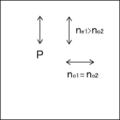
- the refractive index n e1 in the slow axis direction of the optically anisotropic layer is larger than the refractive index n o2 of the isotropic layer, the optically anisotropic layer lagging refractive index n o1 direction perpendicular to the axis is substantially the same as the refractive index n o2 of the isotropic layer.
- the slow axes of the plurality of optically anisotropic layers are laminated so as to be parallel to each other. Accordingly, as shown in FIG. 2, (in FIG.
- the vertical direction is one direction in the in a state in which the refractive index (n e1) is higher layers and the refractive index (n o2) and a lower layer are laminated .
- the refractive index (n e1) is higher layers and the refractive index (n o2) and a lower layer are laminated .
- the direction orthogonal to this one direction left-right direction in FIG. 2
- layers having the same refractive index are laminated.
- a film in which layers having a low refractive index (low refractive index layer) and layers having a high refractive index (high refractive index layer) are alternately laminated has a structural structure between a large number of low refractive index layers and a high refractive index layer. It is known that interference reflects light of a specific wavelength. Therefore, the linearly polarized light reflecting film shown in FIGS. 1 and 2 reflects the linearly polarized light in the vertical direction in FIG. 2 and transmits the linearly polarized light in the left and right direction.
- the reflection spectrum satisfies the above items (i) to (iii).
- the reflected wavelength and the refractive index are adjusted by the refractive index difference, the thickness, the number of layers, etc. between the low refractive index layer and the high refractive index layer. can do.
- the first laminated portion 11 mainly realizes the reflection satisfying the item (i)
- the second laminated portion 12 realizes the reflection satisfying the item (ii)
- the third laminated portion realizes the reflection.
- the part 13 realizes the reflection satisfying the item (iii).
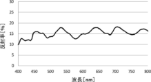
- 3 and 4 show examples of natural light reflection spectra satisfying the above items (i) to (iii).
- the spectrum shown in the graph of FIG. 3 has a first reflection peak near a wavelength of 450 nm.
- the natural light reflectance of this first reflection peak is 10% or more and 20% or less, which satisfies item (i).
- the spectrum shown in the graph of FIG. 3 has a second reflection peak near a wavelength of 530 nm.
- the natural light reflectance of this second reflection peak is 10% or more and 20% or less, which satisfies item (ii).
- the spectrum shown in the graph of FIG. 3 has two third reflection peaks at wavelengths around 640 nm and 700 nm.
- the natural light reflectance of the third reflection peak is 10% or more and 20% or less, respectively, and satisfies item (iii) (a).
- the spectrum shown in the graph of FIG. 4 has a first reflection peak near a wavelength of 460 nm.
- the natural light reflectance of this first reflection peak is 10% or more and 20% or less, which satisfies item (i).
- the spectrum shown in the graph of FIG. 4 has a second reflection peak near a wavelength of 530 nm.
- the natural light reflectance of this second reflection peak is 10% or more and 20% or less, which satisfies item (ii).
- the spectrum shown in the graph of FIG. 4 has a third reflection peak near a wavelength of 690 nm.
- the average value of the maximum value and the minimum value of the reflectance in the band from 600 nm to 800 nm is 16.6%, and the wavelength bandwidth in the region where the reflectance is higher than this is 150 nm.
- the reflection peak is a peak having a maximum value of 2% or more in difference from the adjacent minimum value and a half width of 10 to 200 nm.
- in-vehicle head-up display systems are required to have a transparent appearance color even when viewed from various angles from the viewpoint of transmittance and design that exceed legal regulations.
- it has been considered to reduce the reflectance in order to maintain the transmittance of 70% or more in the regulations and bring the appearance color closer to transparent (white).
- the reflectance is lowered too much, the brightness of the displayed image (projected image) is lowered and the visibility is deteriorated.
- the linearly polarized light reflecting film of the present invention can improve the transparency of color by having a second reflection peak having a reflectance of 10% to 20% at a wavelength of 530 nm or more and less than 600 nm.
- the reflectance of the visual sensitivity around 550 nm is important. Therefore, the transmittance can be ensured by setting the reflectance of the second reflection peak to 20% or less.
- the reflectance near 550 nm in the oblique direction incident angle 60 °
- the linearly polarized reflective film of the present invention has a third reflection peak having a reflectance of 10% to 20% at a wavelength of 600 nm or more and 800 nm or less, and the third reflection peak has two reflection peaks, or a reflection band.
- the width of is 120 nm or more, the front luminance of the displayed image can be improved, and the transparency of the tint when viewed from an oblique direction (incident angle of 60 °) can be improved.
- the front reflection color becomes yellow to red only with the second reflection peak and the third reflection peak.
- the linearly polarized reflective film of the present invention has a first reflection peak having a reflectance of 10% to 20% at a wavelength of 430 nm or more and less than 500 nm, so that the color when viewed from the vicinity of the front surface (incident angle of 5 °).
- the transparency of the taste can be improved.
- a wavelength having low reflectance between the first reflection peak and the second reflection peak and between the second reflection peak and the third reflection peak Since a region is created, the transmittance is improved.
- the natural light transmittance of the windshield glass in which the linearly polarized light reflecting film is sandwiched between green glass can be set to 70% or more (80% or more when the clear glass is sandwiched). Further, the P polarization reflectance can be set to 25% or more, and the brightness of the displayed image can be improved. In addition, the transparency of color when viewed from various directions can be improved.
- the intensity ratio (reflectance ratio) of the first reflection peak and the second reflection peak is 80% or more and 120% or less, and the first reflection peak and the first reflection peak are the first. It is preferable that the intensity ratio of 3 to the reflection peak is 80% or more and 120% or less, and the intensity ratio of the second reflection peak to the third reflection peak is 80% or more and 120% or less.
- the bandwidth of each reflection peak depends on the difference between the refractive index of the optically anisotropic layer in the slow axis direction and the refractive index of the isotropic layer, and the larger the difference in refractive index, the larger the bandwidth. Become. Further, if the reflection peaks having low reflectance are at close wavelengths, they interfere with each other and the reflection peaks become too strong or too weak. Optical anisotropy from the viewpoint of increasing the transmittance while improving the brightness of the displayed image by appropriately adjusting the bandwidth of each reflected peak and reducing the influence of interference with adjacent reflected peaks.
- the difference between the refractive index of the layer in the slow axis direction and the refractive index of the isotropic layer is preferably 0.03 to 0.2, more preferably 0.05 to 0.14. It is more preferably 0.05 to 0.10.
- the wavelength bandwidth of the region where the reflectance is higher than the average value of the maximum value and the minimum value of the reflectance of 430 nm to 500 nm is preferably 20 nm or more and 95 nm or less, and 25 nm or more and 85 nm or less. It is more preferable that it is 30 nm or more and 80 nm or less.
- the wavelength bandwidth of the region where the reflectance is higher than the average value of the maximum value and the minimum value of the reflectance of 530 nm to 600 nm is preferably 20 nm or more and 95 nm or less, and 25 nm or more and 85 nm.
- the wavelength bandwidth of the first reflection peak and the wavelength bandwidth of the second reflection peak are 20 nm or more and 95 nm or less, respectively, that is, the wavelength bandwidths of the first reflection peak and the second reflection peak are narrow. Due to the band, the transmittance can be increased while improving the front luminance of the displayed image.
- the first reflection peak and the second reflection peak are each provided, but even if the first reflection peak and the second reflection peak are each provided by two or more. good.
- the selective reflection layer is composed of two or more light reflection layers having different selective reflection wavelengths, and the light reflection layers having any one of a first reflection peak, a second reflection peak, and a third reflection peak are mutually exclusive. It is preferable that they are in contact with each other.
- a first laminated portion 11 that selectively reflects light having a wavelength of a first reflection peak and a second laminated portion that selectively reflects light having a wavelength of a second reflection peak.
- the second laminated portion 12 which is in contact with each other and selectively reflects the light of the wavelength of the second reflection peak, and the third laminated portion 12 which selectively reflects the light of the wavelength of the third reflection peak.
- the parts 13 are in contact with each other.
- the first laminated portion 11, the second laminated portion 12, and the third laminated portion are the light reflecting layers in the present invention.
- the film thickness between the layers becomes thick and it becomes difficult to obtain the effect of light interference reflected by each light reflecting layer.
- the wavelength bandwidth of each reflected peak can be narrowed due to the effect of the interference of light reflected by each light reflecting layer.
- the linearly polarized light reflective film may be a thin film or a sheet.
- the linearly polarized light reflective film may be in the form of a roll or the like as a thin film before being used for windshield glass.
- the selective reflection layer can be formed by using a wide variety of materials.
- the first material it is necessary for the first material to have a different index of refraction than the second material in the chosen direction.
- This difference in refractive index can be achieved by a variety of methods, including stretching, extrusion, or coating during or after film formation.
- it is preferable to have similar rheological properties eg, melt viscosity
- Materials particularly preferably used as the selective reflective layer include PEN (polyethylene naphthalate) and PET (polyethylene terephthalate) as the optically anisotropic layer, and (isotropically adjusted) as the isotropic layer. ) PEN, PET and PMMA (polymethylmethacrylate resin).
- the linearly polarized light reflection film (selective reflection layer) of the present invention has an optically anisotropic layer and the like so as to have a configuration having a first reflection peak, a second reflection peak and a third reflection peak. It has three laminated parts with different thicknesses of the anisotropic layer.
- each of the three laminated portions may be formed by the above-mentioned stretching, extrusion molding, or the like, and then the laminated portions may be laminated to produce a linearly polarized light reflecting film.
- the thickness before processing may be adjusted so that the three laminated portions having different thicknesses are formed, and the three laminated portions may be integrally formed by stretching, extrusion molding, or the like.
- the thickness of the selective reflective layer is preferably in the range of 2.0 to 50 ⁇ m, more preferably in the range of 8.0 to 30 ⁇ m.
- the linearly polarized light reflective film has a selective reflective layer.
- the linearly polarized light-reflecting film may have a configuration including a retardation layer, a polarization conversion layer, a support, an adhesive layer, and the like in addition to the selective reflection layer.
- the support, the adhesive layer, and the like are both transparent in the visible light region. Further, it is preferable that both the support and the adhesive layer have low birefringence.
- the low birefringence means that the front phase difference is 10 nm or less in the wavelength range in which the linearly polarized light reflecting film of the windshield glass of the present invention exhibits reflection. This front phase difference is preferably 5 nm or less. Further, it is preferable that the difference in the refractive index from the average refractive index (in-plane average refractive index) of the selective reflection layer is small for both the support and the adhesive layer.
- the support can also be used as a substrate when forming the selective reflection layer.
- the support used for forming the selective reflection layer may be a temporary support that is peeled off after the formation of the selective reflection layer. Therefore, the finished linearly polarized reflective film and windshield glass may not include a support.
- the support is preferably transparent in the visible light region.
- the support there are no restrictions on the material of the support.
- the support include polyesters such as polyethylene terephthalate (PET), polycarbonates, acrylic resins, epoxy resins, polyurethanes, polyamides, polyolefins, cellulose derivatives, and plastic films such as silicones.
- PET polyethylene terephthalate
- acrylic resins acrylic resins
- epoxy resins epoxy resins
- polyurethanes polyamides
- polyolefins polyolefins
- cellulose derivatives cellulose derivatives
- plastic films such as silicones.
- glass may be used in addition to the above-mentioned plastic film.
- the thickness of the support may be about 5.0 to 1000 ⁇ m, preferably 10 to 250 ⁇ m, and more preferably 15 to 90 ⁇ m.
- the windshield glass having the linearly polarized light reflecting film of the present invention and the head-up display (HUD) will be described.
- Winddshield glass> By using the linearly polarized light reflective film of the present invention, it is possible to provide a windshield glass having a projected image display function.
- Windshield glass means windows and windshields for vehicles such as cars and trains, airplanes, ships, two-wheeled vehicles, and general vehicles such as playsets.
- the windshield glass is preferably used as a windshield, a windshield, or the like in front of the vehicle in the traveling direction.
- the visible light transmittance of the windshield glass is preferably 70% or more, more preferably more than 70%, further preferably 75% or more, and particularly preferably 80% or more.
- the above-mentioned visible light transmittance is preferably satisfied at any position of the windshield glass, and particularly preferably the above-mentioned visible light transmittance is satisfied at the position where the linearly polarized light reflecting film is present. ..
- the linearly polarized light-reflecting film of the present invention has a high visible light transmittance, so that the above-mentioned visible light transmittance is satisfied regardless of which glass is generally used for the windshield glass. Can be.
- the windshield glass may be, for example, a flat surface or a three-dimensional shape having a curved surface such as a concave surface or a convex surface.
- the upward direction during normal use, the observer side, the driver side, and the visible side surface such as the inside of the vehicle can be specified.
- the windshield glass may have a uniform thickness or a non-uniform thickness at the portion where the linearly polarized light reflecting film is arranged.
- it may have a wedge-shaped cross-sectional shape like the vehicle glass described in Japanese Patent Application Laid-Open No. 2011-505330 and the thickness of the linearly polarized light reflecting film may be non-uniform, but the linearly polarized light reflecting film is arranged. It is preferable that the thickness is uniform in the portion.
- the linearly polarized light reflecting film may be provided at the projected image display portion (projected image reflecting portion) of the windshield glass.
- Head-up using windshield glass by providing the linearly polarized reflective film of the present invention on the outer surface of the glass plate of windshield glass, or by providing it between the glass of windshield glass having a laminated glass structure as described later.
- a display hereinafter, also referred to as HUD can be configured.
- the linearly polarized light reflecting film of the present invention When the linearly polarized light reflecting film of the present invention is provided on the outer surface of the glass plate of the windshield glass, the linearly polarized light reflecting film may be provided inside the vehicle or the like (incident side of the projected image) or outside. However, it is preferable that it is provided inside.
- the linearly polarized light reflective film of the present invention has lower scratch resistance than a glass plate. Therefore, when the windshield glass has a laminated glass structure, it is more preferable that the linearly polarized reflective film is provided between the two pieces of glass constituting the laminated glass in order to protect the linearly polarized reflective film.
- the linearly polarized light reflecting film is a member for displaying a projected image by reflecting the projected image. Therefore, the linearly polarized light-reflecting film may be provided at a position where the projected image projected from the projector or the like can be visually displayed. That is, the linearly polarized light reflective film of the present invention functions as a combiner of the HUD.
- the combiner can visually display the image projected from the projector, and when the combiner is observed from the incident surface side of the projected image, the surface opposite to the incident surface of the projected light such as a landscape. It means an optical member capable of observing information on the side at the same time. That is, the combiner has a function as an optical path combiner that superimposes and displays the outside world light and the light of the projected image.
- the linearly polarized light reflective film may be provided on the entire surface of the windshield glass, or may be provided on a part of the windshield glass in the plane direction, but it is preferable that the linearly polarized light reflective film is provided on a part of the windshield glass.
- the linearly polarized light reflecting film may be provided at any position on the windshield glass, but when used as a HUD, it is easily visible to an observer such as a driver. It is preferably provided so that a virtual image is shown at the position.
- the position where the linearly polarized light reflecting film is provided on the windshield glass may be determined from the relationship between the position of the driver's seat in the vehicle on which the HUD is mounted and the position where the projector is installed.
- the linearly polarized light reflecting film may have a flat surface having no curved surface, but may have a curved surface.
- the linearly polarized light-reflecting film may have a concave or convex shape as a whole, and the projected image may be enlarged or reduced for display.
- the windshield glass may have a laminated glass structure.
- the windshield glass of the present invention is a laminated glass, and has the linearly polarized light reflecting film of the present invention described above between the first glass plate and the second glass plate.
- the windshield glass may have a configuration in which a linearly polarized light reflecting film is arranged between the first glass plate and the second glass plate.
- the windshield glass is provided with an interlayer film (intermediate film sheet) between the first glass plate and the linearly polarized light reflecting film and between the linearly polarized light reflecting film and the second glass plate on at least one of them. It is preferable that the configuration is as follows.
- the first glass plate is arranged on the side opposite to the viewing side (outside the vehicle) of the image in the HUD, and the second glass plate is arranged on the viewing side (inside the vehicle).
- the first and second glass plates in the first glass plate and the second glass plate have no technical meaning, and for convenience in order to distinguish between the two glass plates. It is provided. Therefore, the first glass plate may be on the inside of the vehicle and the second glass plate may be on the outside of the vehicle.
- a glass plate generally used for windshield glass can be used as the glass plate such as the first glass plate and the second glass plate.
- a glass plate having a visible light transmittance of 73%, 76%, or less of 80% or less such as green glass having high heat shielding property, may be used. Even when a glass plate having such a low visible light transmittance is used, by using the linearly polarized light reflecting film of the present invention, the visible light transmittance of 70% or more can be achieved even at the position of the linearly polarized light reflecting film. A windshield glass having can be produced.
- the thickness of the glass plate is not particularly limited, but may be about 0.5 to 5.0 mm, preferably 1.0 to 3.0 mm, and more preferably 2.0 to 2.3 mm.
- the materials or thicknesses of the first glass plate and the second glass plate may be the same or different.
- the windshield glass having a laminated glass structure can be produced by using a known laminated glass manufacturing method. Generally, after sandwiching an interlayer film for laminated glass between two glass plates, heat treatment and pressure treatment (treatment using a rubber roller, etc.) are repeated several times, and finally an autoclave or the like is used. It can be produced by a method of performing heat treatment under pressurized conditions.
- the windshield glass having a structure of a laminated glass having a linearly polarized reflective film and an interlayer film may be produced by the above-mentioned method for producing a laminated glass after forming a linearly polarized reflective film on the surface of a glass plate.
- it may be produced by the above-mentioned method for producing a laminated glass by using an interlayer film for a laminated glass containing the above-mentioned linearly polarized light-reflecting film.
- the glass plate on which the linearly polarized light reflecting film is provided may be either a first glass plate or a second glass plate. At this time, the linearly polarized light reflecting film is bonded to, for example, a glass plate with an adhesive.
- interlayer film As the interlayer film (intermediate film sheet), any known interlayer film used as an intermediate film (intermediate layer) in laminated glass can be used.
- a resin film containing a resin selected from the group of polyvinyl butyral (PVB), ethylene-vinyl acetate copolymer and chlorine-containing resin can be used.
- the above-mentioned resin is preferably the main component of the interlayer film.
- the main component means a component that occupies 50% by mass or more of the interlayer film.
- polyvinyl butyral and ethylene-vinyl acetate copolymer are preferable, and polyvinyl butyral is more preferable.
- the resin is preferably a synthetic resin.
- Polyvinyl butyral can be obtained by acetalizing polyvinyl alcohol with butyraldehyde.
- the preferred lower limit of the degree of acetalization of polyvinyl butyral described above is 40%, the preferred upper limit is 85%, the more preferred lower limit is 60%, and the more preferred upper limit is 75%.
- Polyvinyl alcohol is usually obtained by saponifying polyvinyl acetate, and polyvinyl alcohol having a saponification degree of 80 to 99.8 mol% is generally used. Further, the preferable lower limit of the degree of polymerization of the above-mentioned polyvinyl alcohol is 200, and the preferable upper limit is 3000. When the degree of polymerization of polyvinyl alcohol is 200 or more, the penetration resistance of the obtained laminated glass is unlikely to decrease, and when it is 3000 or less, the moldability of the resin film is good and the rigidity of the resin film does not become too large. Good workability. A more preferred lower limit is 500 and a more preferred upper limit is 2000.
- the interlayer film for laminated glass including the linearly polarized light reflecting film can be formed by laminating the linearly polarized light reflecting film on the surface of the above-mentioned interlayer film.
- the linearly polarized light-reflecting film can be formed by sandwiching it between the two above-mentioned interlayer films.
- the two interlayer films may be the same or different, but are preferably the same.
- a known bonding method can be used for bonding the linearly polarized light reflecting film and the interlayer film, but it is preferable to use a laminating process.
- the laminating treatment is preferably carried out under certain heating and pressurizing conditions so that the laminated body and the interlayer film do not peel off after processing.
- the film surface temperature on the side where the interlayer film is adhered is preferably 50 to 130 ° C, more preferably 70 to 100 ° C. It is preferable to pressurize at the time of laminating.
- the pressurizing conditions are not limited, but less than 2.0 kg / cm 2 (less than 196 kPa) is preferable, 0.5 to 1.8 kg / cm 2 (49 to 176 kPa) is more preferable, and 0.5 to 1.5 kg. / Cm 2 (49-147 kPa) is even more preferred.
- the support When the linearly polarized light reflective film has a support, the support may be peeled off at the same time as laminating, immediately after laminating, or immediately before laminating. That is, the linearly polarized light-reflecting film attached to the interlayer film obtained after laminating may not have a support.
- An example of a method for producing an interlayer film including a linearly polarized light reflecting film is (1) The first step of laminating a linearly polarized light reflecting film on the surface of the first interlayer film to obtain a first laminate, and (2) The second step of laminating the second interlayer film on the surface opposite to the surface to which the first interlayer film of the linearly polarized light reflecting film in the first laminated body is bonded is included. ..
- the linearly polarized light reflecting film and the first interlayer film are bonded together without facing each other between the support and the first interlayer film.
- the support is then stripped from the linearly polarized reflective film.
- the second interlayer film is attached to the surface from which the support has been peeled off. This makes it possible to manufacture an interlayer film containing a linearly polarized light reflecting film having no support.
- the interlayer film containing the linearly polarized light reflecting film it is possible to easily produce a laminated glass in which the linearly polarized light reflecting film does not have a support.
- the temperature of the support when the support is peeled from the linearly polarized light reflective film is preferably 40 ° C. or higher, more preferably 40 to 60 ° C.
- the windshield glass can be used as a component of the HUD.
- the HUD preferably includes a projector.
- a "projector” is a “device that projects light or an image”, includes a “device that projects a drawn image”, and emits projected light that carries an image to be displayed.
- the projector emits p-polarized projected light.
- the projector may be arranged so that the projected light of p-polarized light carrying the image to be displayed can be incident on the linearly polarized light reflecting film in the windshield glass at an oblique incident angle.
- the projector includes a drawing device and reflects and displays an image (real image) drawn on a small intermediate image screen as a virtual image by a combiner.
- a known projector used for the HUD can be used as long as it can emit the projected light of p-polarized light.
- the projector has a variable imaging distance of the virtual image, that is, the imaging position of the virtual image.
- Examples of the method of changing the imaging distance of a virtual image in a projector include a method of moving an image generation surface (screen) (see Japanese Patent Application Laid-Open No. 2017-21302) and a method of switching between a plurality of optical paths having different optical path lengths. (See WO2015 / 190157), a method of changing the optical path length by inserting and / or moving a mirror, a method of changing the focal distance using a group lens as an imaging lens, a method of moving the projector 22, a virtual image imaging method. Examples thereof include a method of switching and using a plurality of projectors having different distances, a method of using a variable focus lens (see WO2010 / 116912), and the like.
- the projector may be one in which the imaging distance of the virtual image can be continuously changed, or one in which the imaging distance of the virtual image can be switched at two points or a plurality of points of three or more points.
- the imaging distance of the virtual image can be switched at two points or a plurality of points of three or more points.
- the virtual images of the projected light by the projector it is preferable that at least two virtual images have different imaging distances of 1 m or more. Therefore, when the projector can continuously change the imaging distance of the virtual image, it is preferable that the imaging distance of the virtual image can be changed by 1 m or more. It is preferable to use such a projector in that it can be suitably used even when the distance of the driver's line of sight is significantly different, such as when traveling at a normal speed on a general road and when traveling at a high speed on an expressway. ..
- the drawing device itself may be a device that displays an image, or may be a device that emits light capable of drawing an image.
- the light from the light source may be adjusted by a drawing method such as an optical modulator, a laser luminance modulation means, or a light deflection means for drawing.
- the drawing device means a device including a light source and further including a light modulator, a laser luminance modulation means, a light deflection means for drawing, and the like depending on the drawing method.
- the light source is not limited, and known light sources such as LEDs (light emitting diodes), organic light emitting diodes (OLEDs), discharge tubes, and laser light sources used in projectors, drawing devices, displays, and the like can be used.
- LEDs and discharge tubes are preferable because they are suitable as a light source for a drawing device that emits linearly polarized light, and LEDs are particularly preferable. This is because the emission wavelength of the LED is not continuous in the visible light region, and therefore, as will be described later, the LED is suitable for combination with a combiner in which a cholesteric liquid crystal layer exhibiting selective reflection in a specific wavelength region is used.
- the drawing method can be selected according to the light source to be used and the like, and is not particularly limited. Examples of drawing methods include a fluorescent display tube, an LCD (Liquid Crystal Display) method that uses a liquid crystal display, an LCOS (Liquid Crystal on Silicon) method, a DLP (registered trademark) (Digital Light Processing) method, and a laser. A scanning method and the like can be mentioned.
- the drawing method may be a method using a fluorescent display tube integrated with a light source.
- the LCD method is preferable as the drawing method.
- the DLP method is a display system using a DMD (Digital Micromirror Device), and is drawn by arranging micromirrors for the number of pixels and emitting light from a projection lens.
- DMD Digital Micromirror Device
- the scanning method is a method in which light rays are scanned on a screen and contrast is performed using the afterimage of the eyes.
- the descriptions in JP-A-7-270711 and JP-A-2013-228674 can be referred to.
- brightness-modulated laser light of each color for example, red light, green light, and blue light
- the light beam is light. It suffices that it is scanned by the deflection means and drawn on the intermediate image screen described later.
- the brightness modulation of the laser light of each color of red light, green light, and blue light may be performed directly as a change in the intensity of the light source, or may be performed by an external modulator.
- the light deflection means include a galvano mirror, a combination of a galvano mirror and a polygon mirror, and a MEMS (Micro Electro Mechanical Systems), of which MEMS is preferable.
- the scanning method include a random scan method and a raster scan method, but it is preferable to use the raster scan method.
- the laser beam can be driven by, for example, a resonance frequency in the horizontal direction and a sawtooth wave in the vertical direction. Since the scanning method does not require a projection lens, the device can be easily miniaturized.
- the light emitted from the drawing device may be linearly polarized light or natural light (non-polarized light).
- the drawing method is an LCD method or an LCOS method and a drawing device using a laser light source
- the emitted light is essentially linearly polarized light.
- the polarization directions (transmission axis direction) of the light having a plurality of wavelengths are the same.
- the drawing device may use an intermediate image screen.
- the "intermediate image screen” is a screen on which an image is drawn. That is, when the light emitted from the drawing device is not yet visible as an image, the drawing device forms a visible image on the intermediate image screen by this light.
- the image drawn on the intermediate image screen may be projected on the combiner by the light transmitted through the intermediate image screen, or may be reflected on the intermediate image screen and projected on the combiner.
- intermediate image screens include a scattering film, a microlens array, a screen for rear projection, and the like.
- a plastic material is used as the intermediate image screen
- the intermediate image screen has birefringence, the polarizing plane and the light intensity of the polarized light incident on the intermediate image screen are disturbed, and the color in the combiner (linearly polarized light reflecting film) is disturbed.
- unevenness and the like are likely to occur, the problem of color unevenness can be reduced by using a retardation film having a predetermined retardation.
- the intermediate image screen preferably has a function of spreading and transmitting incident light rays. This is because the projected image can be enlarged and displayed. Examples of such an intermediate image screen include a screen composed of a microlens array.
- the microarray lens used in the HUD is described in, for example, Japanese Patent Application Laid-Open No. 2012-226303, Japanese Patent Application Laid-Open No. 2010-145745, and Japanese Patent Application Laid-Open No. 2007-523369.
- the projector may include a reflector or the like that adjusts the optical path of the projected light formed by the drawing device.
- JP-A-2-141720, JP-A-10-96874, JP-A-2003-98470, US Pat. No. 5,013,134, and Japanese Patent Application Laid-Open No. 5013134, and Japanese Patent Application Laid-Open No. Table 2006-512622, etc. can be referred to.
- Windshield glass is particularly useful for HUDs that use lasers, LEDs, OLEDs (organic light emitting diodes), etc., whose emission wavelength is not continuous in the visible light region, in combination with a projector as a light source. This is because the center wavelength of the selective reflection of the cholesteric liquid crystal layer can be adjusted according to each emission wavelength. It can also be used for projection of a display such as an LCD (liquid crystal display) in which the display light is polarized.
- LCD liquid crystal display
- the incident light is preferably incident at an oblique incident angle of 45 ° to 70 ° with respect to the normal of the linearly polarized light reflecting film.
- the Brewster angle at the interface between glass with a refractive index of about 1.51 and air with a refractive index of 1 is about 56 °, and by incident p-polarized light within the above angle range, incident light for displaying projected images is used. It is possible to display an image in which the amount of reflected light from the surface of the windshield glass on the visual side is small with respect to the selective reflective layer of the above, and the influence of the double image is small.
- the above-mentioned angle is also preferably 50 ° to 65 °.
- the projected image may be observed at an angle of 45 ° to 70 °, preferably 50 ° to 65 ° on the incident side of the projected light and on the opposite side of the normal line of the selective reflection layer to the incident light. Any configuration can be used.
- the incident light may be incident from any direction such as up, down, left and right of the windshield glass, and may be determined in correspondence with the viewing direction. For example, it is preferable to use a configuration in which the light is incident at an oblique angle of incidence as described above from the lower direction during use. Further, the linearly polarized light reflecting film of the windshield glass may be arranged so as to reflect the incident p-polarized light.
- the projected light at the time of displaying the projected image in the HUD of the present invention is p-polarized light that vibrates in the direction parallel to the incident surface.
- a linearly polarizing film (polarizer) may be provided on the emitted light side of the projector to obtain p-polarized light, and the linearly polarized film may be provided in the optical path from the projector to the windshield glass. Etc. may be used as p-polarized light by a known method.
- a member that converts projected light that is not linearly polarized light into p-polarized light is also considered to constitute the projector in the HUD of the present invention.
- the polarization directions of the emitted light in the red, green, and blue wavelength ranges are not uniform, the polarization directions are adjusted in a wavelength-selective manner and used as p-polarized light in all color wavelength ranges. It is preferable to make it incident.
- the HUD may be a projection system in which the virtual image imaging position is variable.
- the virtual image imaging position is a position where the virtual image can be visually recognized from the driver of the vehicle, for example, a position 1000 mm or more away from the tip of the windshield glass when viewed from the normal driver.
- the glass is non-uniform (wedge-shaped) in the linearly polarized light-reflecting film as described in Japanese Patent Publication No. 2011-505330 described above, the angle of the wedge-shaped image is also changed when the virtual image imaging position is changed. Need to be done. Therefore, for example, as described in Japanese Patent Application Laid-Open No.
- FIG. 5 is a schematic view showing an example of a head-up display having a linearly polarized light reflecting film according to an embodiment of the present invention
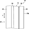
- FIG. 6 shows an example of a windshield glass having a linearly polarized light reflecting film according to the embodiment of the present invention.
- the HUD 20 has a projector 22 and a windshield glass 24, and is used for a vehicle such as a passenger car, for example.
- the components of the HUD 20 have already been described.
- the windshield glass 24 includes a first glass plate 28 which is a first glass plate, a second glass plate 30 which is a second glass plate, and linear polarization reflection. It has a film 10, an interlayer film 36, and an adhesive layer 38.
- the linearly polarized light reflecting film 10 is the linearly polarized light reflecting film 10 shown in FIG. 1, and has a selective reflecting layer in which optically anisotropic layers and isotropic layers are alternately laminated.
- the vertical direction Y of the windshield glass 24 and the axis P of the linearly polarized light reflecting film 10 shown in FIG. 2 are aligned with each other.
- the linearly polarized light reflective film may have a support.
- the vertical direction Y of the windshield glass 24 is a direction corresponding to the top-bottom direction of the vehicle or the like on which the windshield glass 24 is arranged, and is defined as the ground side as the lower side and the opposite side as the upper side.
- the vertical direction Y is on the surface 25 of the windshield glass 24. It will be in the direction along.
- the surface 25 is the outer surface side of the vehicle.
- the projector 22 is as described above.
- a known projector used for the HUD can be used as long as it can emit p-polarized projected light on which the image to be displayed is supported.
- the projector 22 preferably has a variable imaging distance of the virtual image, that is, an imaging position of the virtual image.
- the projector 22 irradiates the windshield glass 24 (second glass plate 30) with the projected light of p-polarized light.
- the reflection of the projected light by the second glass plate 30 and the first glass plate 28 of the windshield glass 24 is significantly reduced, and the reflection is doubled. Inconveniences such as observing an image can be suppressed.
- the projector 22 irradiates the windshield with p-polarized projected light at a Brewster's angle. As a result, the reflection of the projected light on the second glass plate 30 and the first glass plate 28 is eliminated, and a clearer image can be displayed.
- the windshield glass 24 is a so-called laminated glass, and has an interlayer film 36, a linearly polarized light-reflecting film 10, and an adhesive layer 38 between the first glass plate 28 and the second glass plate 30.
- the projected light emitted by the projector 22 is incident from the surface 30a of the second glass plate 30.
- the linearly polarized light reflecting film 10 reflects p-polarized light, and as described above, the axis P shown in FIG. 2, that is, the direction of linearly polarized light reflected by the linearly polarized light reflecting film is set so as to reflect p-polarized light. NS.
- the linearly polarized light reflecting film 10 has a first reflection peak, a second reflection peak, and a third reflection peak as reflection characteristics.
- the linearly polarized light reflective film 10 is attached to the first glass plate 28 by the interlayer film 36, and is attached to the second glass plate 30 by the adhesive layer 38, and the first glass plate 28 and the second glass plate 30 are attached to each other. It is sandwiched between them.
- the first glass plate 28 and the second glass plate 30 of the windshield glass 24 are basically provided in parallel.
- the first glass plate 28 and the second glass plate 30 are both known glasses (glass plates) used for windshields of vehicles and the like. Therefore, the forming material, thickness, shape, etc. may be the same as the glass used for known windshields.
- the first glass plate 28 and the second glass plate 30 shown in FIG. 6 are both flat plates, but the present invention is not limited to this, and a part thereof may be a curved surface or the entire surface may be a curved surface.
- the interlayer film 36 prevents the glass from penetrating into the vehicle and scattering in the event of an accident, and further adheres the linearly polarized light reflecting film 10 and the first glass plate 28.
- a known interlayer film (intermediate layer) used for the windshield of laminated glass can be used.
- the material for forming the interlayer film 36 include polyvinyl butyral (PVB), ethylene-vinyl acetate copolymer, chlorine-containing resin, and polyurethane.
- the thickness of the interlayer film 36 is not limited, and the thickness according to the forming material or the like may be set in the same manner as the known interlayer film of windshield glass.
- the adhesive layer 38 is, for example, a layer made of a coating type adhesive.
- the linearly polarized light reflective film 10 is attached to the second glass plate 30 by the adhesive layer 38.
- the linearly polarized light reflecting film 10 may be attached to the second glass plate 30 by an interlayer film instead of the adhesive layer 38.
- the intermediate film 36 is used to attach the linearly polarized light reflecting film 10 to the second glass. It may be attached to the board 30.
- the adhesive layer 38 is known as long as it has no limitation, can secure the transparency required for the windshield glass 24, and can adhere the linearly polarized light reflective film 10 and the glass with the necessary adhesive force.
- Various coating type adhesives are available.
- the adhesive layer 38 may be the same as the interlayer film 36 such as PVB. In addition to this, an acrylate-based adhesive or the like can also be used for the adhesive layer 38. Further, as the adhesive layer 38, the same adhesive layer as the above-mentioned adhesive layer may be used as shown below.
- the adhesive layer 38 may be formed of an adhesive in the same manner as the above-mentioned adhesive layer.
- the adhesive includes a hot melt type, a thermosetting type, a photocuring type, a reaction curing type, and a pressure-sensitive adhesive type that does not require curing.
- the adhesives of any type are acrylate-based, urethane-based, urethane acrylate-based, epoxy-based, epoxy acrylate-based, polyolefin-based, modified olefin-based, polypropylene-based, ethylene vinyl alcohol-based, vinyl chloride-based, respectively.
- Compounds such as chloroprene rubber-based, cyanoacrylate-based, polyamide-based, polyimide-based, polystyrene-based, and polyvinyl butyral-based compounds can be used.
- the photocurable type is preferable as the curing method, and from the viewpoint of optical transparency and heat resistance, acrylate-based, urethane acrylate-based, epoxy acrylate-based, etc. may be used as the material. preferable.
- the adhesive layer 38 may be formed by using a highly transparent adhesive transfer tape (OCA tape).
- OCA tape a commercially available product for an image display device, particularly a commercially available product for the surface of an image display portion of an image display device may be used.
- Examples of commercially available products include adhesive sheets manufactured by Panac Co., Ltd. (PD-S1 and the like), adhesive sheets of the MHM series manufactured by Niei Kako Co., Ltd., and the like.
- the thickness of the adhesive layer 38 there is no limitation on the thickness of the adhesive layer 38. Therefore, the thickness at which sufficient adhesive force can be obtained may be appropriately set according to the material for forming the adhesive layer 38.
- the thickness of the adhesive layer 38 is preferably 0.1 to 800 ⁇ m, more preferably 0.5 to 400 ⁇ m.
- the windshield glass 24 is provided with an adhesive layer 38 between the linearly polarized light reflecting film 10 and the second glass plate 30, and the linearly polarized light reflecting film 10 and the first glass plate 28 are attached by an interlayer film 36.
- an adhesive layer may be provided between the linearly polarized light reflecting film 10 and the first glass plate 28, and an intermediate film may be provided between the linearly polarized light reflecting film 10 and the second glass plate 30.
- the windshield glass 24 does not have an interlayer film 36, and the linearly polarized light reflecting film 10 and the first glass plate 28 are attached to each other, and the linearly polarized light reflecting film 10 and the second glass plate 30 are attached to each other.
- the structure may be such that the adhesive layer 38 is used.
- the windshield glass 24 has a linearly polarized light-reflecting film 10 between the first glass plate 28 and the second glass plate 30, and the adhesive layer 38 attaches the linearly-polarized reflective film 10 to the second glass plate 30. It has a structure in which the linearly polarized light-reflecting film 10 is attached to the first glass plate 28 by the interlayer film 36.
- the image observer that is, the driver D, observes the virtual image of the projected image by the projector 22 projected by the projector 22 and reflected by the windshield glass 24.
- the projected image of the projector is reflected by the glass of the windshield, and the reflected light is observed.
- a general windshield is a laminated glass and has two pieces of glass, an inner surface side and an outer surface side. Therefore, in the HUD, there is a problem that a double image is observed by the driver due to the reflected light of the two glasses.
- the cross-sectional shape of the windshield is made wedge-shaped so that the reflection of the inner glass and the reflection of the outer glass overlap, and the double image cannot be seen. I am trying to do it.
- the wedge-shaped windshield for example, when the imaging distance of the virtual image is changed in order to cope with the difference in the driver's line of sight between normal driving where the line of sight is close and high-speed driving where the line of sight is far away. , The angle of the wedge of the windshield does not match, and the image observed by the driver becomes a double image.
- the projector 22 projects p-polarized light
- the windshield glass 24 reflects p-polarized light between the first glass plate 28 and the second glass plate 30.
- the driver D observes the reflected light by the linearly polarized light reflecting film 10.
- the reflection of the projected light of the projector 22 is basically dominated by the reflection of the linearly polarized light reflecting film 10, so that a double image is basically unlikely to occur.
- the HUD 20 using the linearly polarized light reflecting film 10 of the present invention for the windshield glass 24 it is not necessary to make the cross-sectional shape of the windshield glass 24 (intermediate film 36) a wedge shape, and therefore, the imaging distance of the virtual image is changed. However, no double image is generated.
- the present invention is basically configured as described above.
- the linearly polarized reflective film, the windshield glass, and the head-up display system (HUD) of the present invention have been described in detail above, but the present invention is not limited to the above-described embodiment, and the present invention is not limited to the above-described embodiment and does not deviate from the gist of the present invention. Of course, various improvements or changes may be made.
- Example 1 ⁇ Manufacturing of linearly polarized light reflective film> A linearly polarized light reflecting film (selective reflective layer) was produced as follows based on the method described in Japanese Patent Publication No. 9-506837.
- PEN 2,6-Polyethylene naphthalate
- coPEN copolyester
- naphthalate 70 / terephthalate 30 2,6-Polyethylene naphthalate
- PEN and coPEN single layer films After extrusion molding of PEN and coPEN single layer films, they were stretched at about 150 ° C. at a stretching ratio of 5: 1 and heat-treated at about 230 ° C. for 30 seconds. It was confirmed that the refractive index of PEN with respect to the slow axis (orientation axis) was about 1.86, the refractive index with respect to the transverse axis was 1.64, and the refractive index of the coPEN film was about 1.64.
- the refractive index of PEN with respect to the slow-phase axis is about 1.71
- the refractive index with respect to the transverse axis is 1.64
- the refractive index of the coPEN film is about 1.64. confirmed. That is, the difference ⁇ n between the refractive index of the optically anisotropic layer in the slow axis direction and the refractive index of the isotropic layer is 0.07.
- the stretched laminate was heat-treated in an air oven at about 230 ° C. for 30 seconds to prepare a linearly polarized light-reflecting film.
- the thickness of the produced linearly polarized light reflecting film was about 10 ⁇ m.
- Examples 2 to 4, Comparative Examples 1 to 3 The refractive index of the PEN layer in the slow axis direction, that is, the difference between the refractive index of the optically anisotropic layer in the slow axis direction and the refractive index of the isotropic layer ⁇ n, the PEN layer (optically anisotropic layer) and coPEN.
- the film thickness and the number of layers of the layers (in the slow axis direction) were appropriately changed to prepare a linearly polarized reflective film having the reflection peaks shown in Table 2 below.
- Table 2 below shows the wavelengths, reflectances, wavelength bands, and the presence or absence of contact between the light reflecting layers of the reflected peaks of each example and comparative example. In Table 2, when there are a plurality of third reflection peaks, each reflection peak is distinguished as a third A, a third B, a third C, and a third D.
- the intensity ratio of the first reflection peak, the second reflection peak, and the third reflection peak is 80% or more and 120% or less.
- the intensity ratio of the first reflection peak to the second reflection peak is 150%, and the intensity ratio of the first reflection peak to the third reflection peak is 125%.
- the reflectance and the wavelength bandwidth at each reflection peak in each Example and Comparative Example were measured as follows.
- the produced linearly polarized light-reflecting film was attached to the front surface of the glass plate, and a black PET film (light absorber) was attached to the back surface of the glass plate.
- a spectrophotometer manufactured by JASCO Corporation, V-670
- P-polarized light and S-polarized light are incident from the surface of the linearly polarized light-reflecting film from a direction of 5 ° to the normal direction, respectively, and reflected from 400 nm to 1000 nm.
- the spectra were measured respectively.
- the average value (average reflection spectrum) of the measured P-polarized light reflection spectrum and S-polarized light reflection spectrum was obtained.
- the average value of the reflectance when P-polarized light is incident and the reflectance when S-polarized light is incident is synonymous with the reflectance when unpolarized light (natural light) is incident. That is, the average value of the P-polarized light reflection spectrum and the S-polarized light reflection spectrum is synonymous with the reflection spectrum when natural light is incident.
- the reflection peak (maximum value) in the wavelength band of 430 nm to 500 nm is extracted as the first reflection peak, and its reflectance and wavelength bandwidth are calculated.
- the reflection peak (maximum value) in the wavelength band of 530 nm to 600 nm is extracted as the second reflection peak, and its reflectance and wavelength bandwidth are calculated.
- the reflection peak (maximum value) in the band of wavelength 600 nm to 800 nm was extracted as the third reflection peak, and the number of peaks, the reflectance and the wavelength bandwidth were calculated.
- the wavelength bandwidth of the first reflection peak is the width of a region where the reflectance is higher than the average value of the maximum value and the minimum value of the reflectance in the band having a wavelength of 430 nm to 500 nm.
- the wavelength bandwidth of the second reflection peak is the width of a region where the reflectance is higher than the average value of the maximum value and the minimum value of the reflectance in the band having a wavelength of 530 nm to 600 nm.
- the wavelength bandwidth of the third reflection peak is the width of a region where the reflectance is higher than the average value of the maximum value and the minimum value of the reflectance in the band having a wavelength of 600 nm to 800 nm.
- the first reflection peak and the second reflection peak overlap each other, and the wavelength bandwidth extends from a region having a wavelength of 430 nm to 500 nm to a region having a wavelength of 530 nm to 600 nm.
- the windshield glass having each linearly polarized light reflecting film produced above was produced as follows.
- a glass plate (manufactured by Central Glass Co., Ltd., FL2, visible light transmittance 90%) having a length of 120 mm, a width of 100 mm, and a thickness of 2 mm was prepared.
- a PVB film was placed as an interlayer film having a thickness of 0.38 mm manufactured by Sekisui Chemical Co., Ltd., which was cut to the same size.
- a sheet-shaped linearly polarized light-reflecting film cut into a size of 110 mm in length ⁇ 90 mm in width was placed on the interlayer film with the slow phase axial direction aligned with the vertical direction.
- a glass plate (manufactured by Central Glass Co., Ltd., FL2, visible light transmittance 90%) having a length of 120 mm, a width of 100 mm, and a thickness of 2 mm was placed on the linearly polarized light-reflecting film.
- This laminate was held at 90 ° C. and 10 kPa (0.1 atm) for 1 hour, and then heated in an autoclave (manufactured by Kurihara Seisakusho) at 115 ° C. and 1.3 MPa (13 atm) for 20 minutes to remove air bubbles. , Obtained a windshield glass.
- the projected image reflectance was calculated by multiplying the reflectance by a coefficient corresponding to the visual sensitivity and the emission spectrum of the D65 light source at wavelengths of every 10 nm from 380 to 780 nm, and evaluated as brightness.
- the brightness was evaluated according to the following evaluation criteria.
- the examples give better results in terms of transmittance, P-polarized reflectance (luminance), and reflected tint as compared with the comparative examples.
- the difference ⁇ n between the refractive index of the optically anisotropic layer in the slow axis direction and the refractive index of the isotropic layer is preferably 0.05 to 0.14, and is 0. It can be seen that it is more preferably 0.05 to 0.10.
- the intensity ratio of each reflected peak is preferably 80% or more and 120% or less. From the above results, the effect of the present invention is clear.
- HUD head-up display system
Landscapes
- Physics & Mathematics (AREA)
- General Physics & Mathematics (AREA)
- Optics & Photonics (AREA)
- Engineering & Computer Science (AREA)
- Chemical & Material Sciences (AREA)
- Combustion & Propulsion (AREA)
- Transportation (AREA)
- Mechanical Engineering (AREA)
- Instrument Panels (AREA)
- Polarising Elements (AREA)
- Laminated Bodies (AREA)
Priority Applications (4)
| Application Number | Priority Date | Filing Date | Title |
|---|---|---|---|
| JP2022512115A JP7465950B2 (ja) | 2020-03-30 | 2021-03-26 | 直線偏光反射フィルム、ウインドシールドガラスおよびヘッドアップディスプレイシステム |
| CN202180026831.4A CN115461658B (zh) | 2020-03-30 | 2021-03-26 | 线偏振光反射膜、挡风玻璃及平视显示器系统 |
| EP21782212.1A EP4130816A4 (en) | 2020-03-30 | 2021-03-26 | Linearly polarized light reflection film, windshield glass, and head-up display system |
| US17/956,545 US12517294B2 (en) | 2020-03-30 | 2022-09-29 | Linearly polarized light reflection film, windshield glass, and head-up display system |
Applications Claiming Priority (4)
| Application Number | Priority Date | Filing Date | Title |
|---|---|---|---|
| JP2020059979 | 2020-03-30 | ||
| JP2020-059979 | 2020-03-30 | ||
| JP2020190429 | 2020-11-16 | ||
| JP2020-190429 | 2020-11-16 |
Related Child Applications (1)
| Application Number | Title | Priority Date | Filing Date |
|---|---|---|---|
| US17/956,545 Continuation US12517294B2 (en) | 2020-03-30 | 2022-09-29 | Linearly polarized light reflection film, windshield glass, and head-up display system |
Publications (1)
| Publication Number | Publication Date |
|---|---|
| WO2021200652A1 true WO2021200652A1 (ja) | 2021-10-07 |
Family
ID=77930016
Family Applications (1)
| Application Number | Title | Priority Date | Filing Date |
|---|---|---|---|
| PCT/JP2021/012859 Ceased WO2021200652A1 (ja) | 2020-03-30 | 2021-03-26 | 直線偏光反射フィルム、ウインドシールドガラスおよびヘッドアップディスプレイシステム |
Country Status (5)
| Country | Link |
|---|---|
| US (1) | US12517294B2 (https=) |
| EP (1) | EP4130816A4 (https=) |
| JP (1) | JP7465950B2 (https=) |
| CN (1) | CN115461658B (https=) |
| WO (1) | WO2021200652A1 (https=) |
Cited By (6)
| Publication number | Priority date | Publication date | Assignee | Title |
|---|---|---|---|---|
| WO2022123946A1 (ja) * | 2020-12-09 | 2022-06-16 | 富士フイルム株式会社 | 反射フィルム、ウインドシールドガラスおよびヘッドアップディスプレイシステム |
| JPWO2023080115A1 (https=) * | 2021-11-05 | 2023-05-11 | ||
| WO2023080116A1 (ja) * | 2021-11-05 | 2023-05-11 | 富士フイルム株式会社 | 反射フィルム、ウインドシールドガラス、ヘッドアップディスプレイシステム及びこのヘッドアップディスプレイシステムを有する輸送機 |
| WO2025100231A1 (ja) * | 2023-11-06 | 2025-05-15 | 富士フイルム株式会社 | ウインドシールドガラスおよびヘッドアップディスプレイシステム |
| WO2025173666A1 (ja) * | 2024-02-14 | 2025-08-21 | 富士フイルム株式会社 | コンバイナー、ヘッドアップディスプレイシステム |
| JP7855602B2 (ja) | 2021-11-05 | 2026-05-08 | 富士フイルム株式会社 | 虚像表示装置、ヘッドアップディスプレイシステム及び輸送機 |
Families Citing this family (2)
| Publication number | Priority date | Publication date | Assignee | Title |
|---|---|---|---|---|
| JP7454649B2 (ja) * | 2020-03-30 | 2024-03-22 | 富士フイルム株式会社 | 反射フィルム、ウインドシールドガラスおよびヘッドアップディスプレイシステム |
| US20230213758A1 (en) * | 2021-12-30 | 2023-07-06 | 3M Innovative Properties Company | Multiband resonant gratings |
Citations (21)
| Publication number | Priority date | Publication date | Assignee | Title |
|---|---|---|---|---|
| JPH02141720A (ja) | 1988-11-23 | 1990-05-31 | Nippon Denso Co Ltd | ヘッドアップディスプレイ装置 |
| US5013134A (en) | 1989-09-28 | 1991-05-07 | Hughes Aircraft Company | Ghost-free automotive head-up display employing a wedged windshield |
| JPH07270711A (ja) | 1994-03-30 | 1995-10-20 | Canon Inc | 情報表示装置 |
| JPH09506837A (ja) | 1993-12-21 | 1997-07-08 | ミネソタ・マイニング・アンド・マニュファクチュアリング・カンパニー | 多層光学フィルム |
| JPH1096874A (ja) | 1996-05-24 | 1998-04-14 | Asahi Glass Co Ltd | 車両用ウインドシールドガラスおよびヘッドアップディスプレイ装置 |
| JP2000221449A (ja) | 1999-01-29 | 2000-08-11 | Arisawa Mfg Co Ltd | 映像装置 |
| JP2003098470A (ja) | 2001-09-21 | 2003-04-03 | Asahi Glass Co Ltd | ヘッドアップディスプレイ装置 |
| JP2006512622A (ja) | 2002-12-31 | 2006-04-13 | スリーエム イノベイティブ プロパティズ カンパニー | 偏光光源および広角p偏光反射偏光子を備えたヘッドアップディスプレイ |
| JP2007523369A (ja) | 2004-02-04 | 2007-08-16 | マイクロビジョン,インク. | 走査ビームヘッドアップ表示装置および関連システム、および方法 |
| JP2010145745A (ja) | 2008-12-18 | 2010-07-01 | Equos Research Co Ltd | 画像形成装置、及び、ヘッドアップディスプレイ装置 |
| WO2010116912A1 (ja) | 2009-04-08 | 2010-10-14 | 国立大学法人東京大学 | トラッキング装置およびこのトラッキング装置を備えたトラッキング顕微鏡並びにトラッキング方法 |
| JP2011505330A (ja) | 2007-12-07 | 2011-02-24 | サン−ゴバン グラス フランス | 合わせガラスからなる曲面の車両用フロントガラス |
| JP2012226303A (ja) | 2011-12-21 | 2012-11-15 | Pioneer Electronic Corp | 光源ユニット及びヘッドアップディスプレイ |
| JP2013228674A (ja) | 2012-03-28 | 2013-11-07 | Nippon Seiki Co Ltd | 車両用表示装置 |
| WO2015190157A1 (ja) | 2014-06-13 | 2015-12-17 | 三菱電機株式会社 | 虚像表示装置 |
| WO2016056617A1 (ja) | 2014-10-10 | 2016-04-14 | 日本化薬株式会社 | 光反射フィルム、ならびにこれを用いた光制御フィルム、光学フィルム、機能性ガラスおよびヘッドアップディスプレイ |
| JP2017007565A (ja) * | 2015-06-24 | 2017-01-12 | 富士フイルム株式会社 | 車両用の画像表示機能付きミラー |
| JP2017015902A (ja) | 2015-06-30 | 2017-01-19 | パナソニックIpマネジメント株式会社 | 表示装置、表示方法および表示媒体 |
| JP2017021302A (ja) | 2015-07-15 | 2017-01-26 | 日本精機株式会社 | ヘッドアップディスプレイ |
| JP2018017839A (ja) * | 2016-07-27 | 2018-02-01 | 日本化薬株式会社 | 機能性ガラスおよびこれを用いたヘッドアップディスプレイ |
| WO2019146423A1 (ja) * | 2018-01-25 | 2019-08-01 | 富士フイルム株式会社 | 投映像表示用部材、ウインドシールドガラスおよびヘッドアップディスプレイシステム |
Family Cites Families (4)
| Publication number | Priority date | Publication date | Assignee | Title |
|---|---|---|---|---|
| CN104412133A (zh) * | 2012-06-28 | 2015-03-11 | 可隆工业株式会社 | 增亮膜及含有该增亮膜的背光单元 |
| JP6460732B2 (ja) * | 2014-11-10 | 2019-01-30 | 住友化学株式会社 | 光学積層体、液晶パネル及び液晶表示装置 |
| JP2017187685A (ja) * | 2016-04-07 | 2017-10-12 | 日本化薬株式会社 | 曲面形状の光反射フィルム及びその製造方法、ならびに当該光反射フィルムを用いた光制御フィルム、光学フィルム、機能性ガラスおよびヘッドアップディスプレイ |
| JP6896533B2 (ja) * | 2017-07-04 | 2021-06-30 | 富士フイルム株式会社 | ヘッドアップディスプレイ |
-
2021
- 2021-03-26 WO PCT/JP2021/012859 patent/WO2021200652A1/ja not_active Ceased
- 2021-03-26 JP JP2022512115A patent/JP7465950B2/ja active Active
- 2021-03-26 CN CN202180026831.4A patent/CN115461658B/zh active Active
- 2021-03-26 EP EP21782212.1A patent/EP4130816A4/en active Pending
-
2022
- 2022-09-29 US US17/956,545 patent/US12517294B2/en active Active
Patent Citations (21)
| Publication number | Priority date | Publication date | Assignee | Title |
|---|---|---|---|---|
| JPH02141720A (ja) | 1988-11-23 | 1990-05-31 | Nippon Denso Co Ltd | ヘッドアップディスプレイ装置 |
| US5013134A (en) | 1989-09-28 | 1991-05-07 | Hughes Aircraft Company | Ghost-free automotive head-up display employing a wedged windshield |
| JPH09506837A (ja) | 1993-12-21 | 1997-07-08 | ミネソタ・マイニング・アンド・マニュファクチュアリング・カンパニー | 多層光学フィルム |
| JPH07270711A (ja) | 1994-03-30 | 1995-10-20 | Canon Inc | 情報表示装置 |
| JPH1096874A (ja) | 1996-05-24 | 1998-04-14 | Asahi Glass Co Ltd | 車両用ウインドシールドガラスおよびヘッドアップディスプレイ装置 |
| JP2000221449A (ja) | 1999-01-29 | 2000-08-11 | Arisawa Mfg Co Ltd | 映像装置 |
| JP2003098470A (ja) | 2001-09-21 | 2003-04-03 | Asahi Glass Co Ltd | ヘッドアップディスプレイ装置 |
| JP2006512622A (ja) | 2002-12-31 | 2006-04-13 | スリーエム イノベイティブ プロパティズ カンパニー | 偏光光源および広角p偏光反射偏光子を備えたヘッドアップディスプレイ |
| JP2007523369A (ja) | 2004-02-04 | 2007-08-16 | マイクロビジョン,インク. | 走査ビームヘッドアップ表示装置および関連システム、および方法 |
| JP2011505330A (ja) | 2007-12-07 | 2011-02-24 | サン−ゴバン グラス フランス | 合わせガラスからなる曲面の車両用フロントガラス |
| JP2010145745A (ja) | 2008-12-18 | 2010-07-01 | Equos Research Co Ltd | 画像形成装置、及び、ヘッドアップディスプレイ装置 |
| WO2010116912A1 (ja) | 2009-04-08 | 2010-10-14 | 国立大学法人東京大学 | トラッキング装置およびこのトラッキング装置を備えたトラッキング顕微鏡並びにトラッキング方法 |
| JP2012226303A (ja) | 2011-12-21 | 2012-11-15 | Pioneer Electronic Corp | 光源ユニット及びヘッドアップディスプレイ |
| JP2013228674A (ja) | 2012-03-28 | 2013-11-07 | Nippon Seiki Co Ltd | 車両用表示装置 |
| WO2015190157A1 (ja) | 2014-06-13 | 2015-12-17 | 三菱電機株式会社 | 虚像表示装置 |
| WO2016056617A1 (ja) | 2014-10-10 | 2016-04-14 | 日本化薬株式会社 | 光反射フィルム、ならびにこれを用いた光制御フィルム、光学フィルム、機能性ガラスおよびヘッドアップディスプレイ |
| JP2017007565A (ja) * | 2015-06-24 | 2017-01-12 | 富士フイルム株式会社 | 車両用の画像表示機能付きミラー |
| JP2017015902A (ja) | 2015-06-30 | 2017-01-19 | パナソニックIpマネジメント株式会社 | 表示装置、表示方法および表示媒体 |
| JP2017021302A (ja) | 2015-07-15 | 2017-01-26 | 日本精機株式会社 | ヘッドアップディスプレイ |
| JP2018017839A (ja) * | 2016-07-27 | 2018-02-01 | 日本化薬株式会社 | 機能性ガラスおよびこれを用いたヘッドアップディスプレイ |
| WO2019146423A1 (ja) * | 2018-01-25 | 2019-08-01 | 富士フイルム株式会社 | 投映像表示用部材、ウインドシールドガラスおよびヘッドアップディスプレイシステム |
Cited By (9)
| Publication number | Priority date | Publication date | Assignee | Title |
|---|---|---|---|---|
| WO2022123946A1 (ja) * | 2020-12-09 | 2022-06-16 | 富士フイルム株式会社 | 反射フィルム、ウインドシールドガラスおよびヘッドアップディスプレイシステム |
| JPWO2022123946A1 (https=) * | 2020-12-09 | 2022-06-16 | ||
| US12072597B2 (en) | 2020-12-09 | 2024-08-27 | Fujifilm Corporation | Reflection film, windshield glass, and head-up display system |
| JP7649800B2 (ja) | 2020-12-09 | 2025-03-21 | 富士フイルム株式会社 | 反射フィルム、ウインドシールドガラスおよびヘッドアップディスプレイシステム |
| JPWO2023080115A1 (https=) * | 2021-11-05 | 2023-05-11 | ||
| WO2023080116A1 (ja) * | 2021-11-05 | 2023-05-11 | 富士フイルム株式会社 | 反射フィルム、ウインドシールドガラス、ヘッドアップディスプレイシステム及びこのヘッドアップディスプレイシステムを有する輸送機 |
| JP7855602B2 (ja) | 2021-11-05 | 2026-05-08 | 富士フイルム株式会社 | 虚像表示装置、ヘッドアップディスプレイシステム及び輸送機 |
| WO2025100231A1 (ja) * | 2023-11-06 | 2025-05-15 | 富士フイルム株式会社 | ウインドシールドガラスおよびヘッドアップディスプレイシステム |
| WO2025173666A1 (ja) * | 2024-02-14 | 2025-08-21 | 富士フイルム株式会社 | コンバイナー、ヘッドアップディスプレイシステム |
Also Published As
| Publication number | Publication date |
|---|---|
| JPWO2021200652A1 (https=) | 2021-10-07 |
| JP7465950B2 (ja) | 2024-04-11 |
| CN115461658A (zh) | 2022-12-09 |
| US20230035433A1 (en) | 2023-02-02 |
| US12517294B2 (en) | 2026-01-06 |
| CN115461658B (zh) | 2025-08-19 |
| EP4130816A4 (en) | 2023-11-22 |
| EP4130816A1 (en) | 2023-02-08 |
Similar Documents
| Publication | Publication Date | Title |
|---|---|---|
| CN115461658B (zh) | 线偏振光反射膜、挡风玻璃及平视显示器系统 | |
| JP7601011B2 (ja) | ヘッドアップディスプレイシステム | |
| JP7764389B2 (ja) | 反射フィルム、ウインドシールドガラス、および、ヘッドアップディスプレイシステム | |
| US11947109B2 (en) | Projection image-displaying member, windshield glass, and head-up display system | |
| US11314087B2 (en) | Projection image-displaying member, windshield glass, and head-up display system | |
| JP7454649B2 (ja) | 反射フィルム、ウインドシールドガラスおよびヘッドアップディスプレイシステム | |
| WO2015177833A1 (ja) | 虚像生成素子及びヘッドアップディスプレイ | |
| WO2023080115A1 (ja) | 虚像表示装置、ヘッドアップディスプレイシステム及び輸送機 | |
| CN116568545A (zh) | 反射膜、挡风玻璃及平视显示系统 | |
| US20230102484A1 (en) | Reflective film, method for producing laminated glass, and laminated glass | |
| JP2019003011A (ja) | 積層体、合わせガラス、ウィンドシールドガラス、映像表示システム | |
| JP7842114B2 (ja) | ヘッドアップディスプレイシステム及び輸送機 | |
| JP7803678B2 (ja) | ヘッドアップディスプレイシステム及びそれを有する輸送機 | |
| WO2021200697A1 (ja) | ウインドシールドガラスおよびヘッドアップディスプレイシステム | |
| US20260003186A1 (en) | Windshield glass and head-up display system | |
| WO2025100231A1 (ja) | ウインドシールドガラスおよびヘッドアップディスプレイシステム | |
| JP2025097638A (ja) | 車両用表示システム | |
| CN118584665A (zh) | 基于光源装置和光学薄膜的图像信息显示系统 |
Legal Events
| Date | Code | Title | Description |
|---|---|---|---|
| 121 | Ep: the epo has been informed by wipo that ep was designated in this application |
Ref document number: 21782212 Country of ref document: EP Kind code of ref document: A1 |
|
| ENP | Entry into the national phase |
Ref document number: 2022512115 Country of ref document: JP Kind code of ref document: A |
|
| NENP | Non-entry into the national phase |
Ref country code: DE |
|
| ENP | Entry into the national phase |
Ref document number: 2021782212 Country of ref document: EP Effective date: 20221031 |
|
| WWG | Wipo information: grant in national office |
Ref document number: 202180026831.4 Country of ref document: CN |