WO2021200652A1 - Linearly polarized light reflection film, windshield glass, and head-up display system - Google Patents
Linearly polarized light reflection film, windshield glass, and head-up display system Download PDFInfo
- Publication number
- WO2021200652A1 WO2021200652A1 PCT/JP2021/012859 JP2021012859W WO2021200652A1 WO 2021200652 A1 WO2021200652 A1 WO 2021200652A1 JP 2021012859 W JP2021012859 W JP 2021012859W WO 2021200652 A1 WO2021200652 A1 WO 2021200652A1
- Authority
- WO
- WIPO (PCT)
- Prior art keywords
- reflection
- linearly polarized
- light
- polarized light
- reflection peak
- Prior art date
Links
- 239000011521 glass Substances 0.000 title claims abstract description 217
- 238000002834 transmittance Methods 0.000 abstract description 43
- 239000010408 film Substances 0.000 description 224
- 239000010410 layer Substances 0.000 description 126
- 239000011229 interlayer Substances 0.000 description 42
- 238000000034 method Methods 0.000 description 42
- 239000012790 adhesive layer Substances 0.000 description 28
- 239000005340 laminated glass Substances 0.000 description 22
- 238000003384 imaging method Methods 0.000 description 20
- 238000001228 spectrum Methods 0.000 description 19
- 239000000463 material Substances 0.000 description 15
- 239000000853 adhesive Substances 0.000 description 13
- 230000001070 adhesive effect Effects 0.000 description 13
- 230000003287 optical effect Effects 0.000 description 12
- 230000010287 polarization Effects 0.000 description 12
- 229920002037 poly(vinyl butyral) polymer Polymers 0.000 description 11
- 239000011112 polyethylene naphthalate Substances 0.000 description 11
- 238000010030 laminating Methods 0.000 description 10
- 229920003207 poly(ethylene-2,6-naphthalate) Polymers 0.000 description 10
- 229920005989 resin Polymers 0.000 description 10
- 239000011347 resin Substances 0.000 description 10
- 238000011156 evaluation Methods 0.000 description 8
- 238000004519 manufacturing process Methods 0.000 description 7
- 230000033228 biological regulation Effects 0.000 description 6
- 239000004372 Polyvinyl alcohol Substances 0.000 description 5
- 230000008859 change Effects 0.000 description 5
- 230000000052 comparative effect Effects 0.000 description 5
- 238000001125 extrusion Methods 0.000 description 5
- 229920002451 polyvinyl alcohol Polymers 0.000 description 5
- 230000015572 biosynthetic process Effects 0.000 description 4
- 238000001723 curing Methods 0.000 description 4
- 238000010586 diagram Methods 0.000 description 4
- 230000000694 effects Effects 0.000 description 4
- 239000004973 liquid crystal related substance Substances 0.000 description 4
- -1 polyethylene naphthalate Polymers 0.000 description 4
- 239000005020 polyethylene terephthalate Substances 0.000 description 4
- 229920000139 polyethylene terephthalate Polymers 0.000 description 4
- 230000000007 visual effect Effects 0.000 description 4
- NIXOWILDQLNWCW-UHFFFAOYSA-M Acrylate Chemical compound [O-]C(=O)C=C NIXOWILDQLNWCW-UHFFFAOYSA-M 0.000 description 3
- LYCAIKOWRPUZTN-UHFFFAOYSA-N Ethylene glycol Chemical compound OCCO LYCAIKOWRPUZTN-UHFFFAOYSA-N 0.000 description 3
- 239000011248 coating agent Substances 0.000 description 3
- 238000000576 coating method Methods 0.000 description 3
- 239000003086 colorant Substances 0.000 description 3
- 238000013461 design Methods 0.000 description 3
- 239000005038 ethylene vinyl acetate Substances 0.000 description 3
- 238000010438 heat treatment Methods 0.000 description 3
- 238000005259 measurement Methods 0.000 description 3
- 229920001200 poly(ethylene-vinyl acetate) Polymers 0.000 description 3
- 238000012545 processing Methods 0.000 description 3
- 230000035945 sensitivity Effects 0.000 description 3
- ZTQSAGDEMFDKMZ-UHFFFAOYSA-N Butyraldehyde Chemical compound CCCC=O ZTQSAGDEMFDKMZ-UHFFFAOYSA-N 0.000 description 2
- ZAMOUSCENKQFHK-UHFFFAOYSA-N Chlorine atom Chemical compound [Cl] ZAMOUSCENKQFHK-UHFFFAOYSA-N 0.000 description 2
- 239000004986 Cholesteric liquid crystals (ChLC) Substances 0.000 description 2
- 230000005540 biological transmission Effects 0.000 description 2
- 238000006243 chemical reaction Methods 0.000 description 2
- 239000000460 chlorine Substances 0.000 description 2
- 229910052801 chlorine Inorganic materials 0.000 description 2
- 150000001875 compounds Chemical class 0.000 description 2
- 238000000295 emission spectrum Methods 0.000 description 2
- UHESRSKEBRADOO-UHFFFAOYSA-N ethyl carbamate;prop-2-enoic acid Chemical compound OC(=O)C=C.CCOC(N)=O UHESRSKEBRADOO-UHFFFAOYSA-N 0.000 description 2
- 239000002985 plastic film Substances 0.000 description 2
- 229920006255 plastic film Polymers 0.000 description 2
- 229920003229 poly(methyl methacrylate) Polymers 0.000 description 2
- 229920002647 polyamide Polymers 0.000 description 2
- 238000006116 polymerization reaction Methods 0.000 description 2
- 239000004926 polymethyl methacrylate Substances 0.000 description 2
- 229920000098 polyolefin Polymers 0.000 description 2
- 229920002635 polyurethane Polymers 0.000 description 2
- 239000004814 polyurethane Substances 0.000 description 2
- KCTAWXVAICEBSD-UHFFFAOYSA-N prop-2-enoyloxy prop-2-eneperoxoate Chemical compound C=CC(=O)OOOC(=O)C=C KCTAWXVAICEBSD-UHFFFAOYSA-N 0.000 description 2
- 239000010409 thin film Substances 0.000 description 2
- 238000012546 transfer Methods 0.000 description 2
- HXNBAOLVPAWYLT-NVNXTCNLSA-N (5z)-5-[[5-bromo-2-[(2-bromophenyl)methoxy]phenyl]methylidene]-2-sulfanylidene-1,3-thiazolidin-4-one Chemical compound S\1C(=S)NC(=O)C/1=C/C1=CC(Br)=CC=C1OCC1=CC=CC=C1Br HXNBAOLVPAWYLT-NVNXTCNLSA-N 0.000 description 1
- 229920000178 Acrylic resin Polymers 0.000 description 1
- 239000004925 Acrylic resin Substances 0.000 description 1
- 238000012935 Averaging Methods 0.000 description 1
- 229920002799 BoPET Polymers 0.000 description 1
- 229920001634 Copolyester Polymers 0.000 description 1
- 229920001651 Cyanoacrylate Polymers 0.000 description 1
- 239000004593 Epoxy Substances 0.000 description 1
- JOYRKODLDBILNP-UHFFFAOYSA-N Ethyl urethane Chemical compound CCOC(N)=O JOYRKODLDBILNP-UHFFFAOYSA-N 0.000 description 1
- 229920000219 Ethylene vinyl alcohol Polymers 0.000 description 1
- 125000002066 L-histidyl group Chemical group [H]N1C([H])=NC(C([H])([H])[C@](C(=O)[*])([H])N([H])[H])=C1[H] 0.000 description 1
- MWCLLHOVUTZFKS-UHFFFAOYSA-N Methyl cyanoacrylate Chemical compound COC(=O)C(=C)C#N MWCLLHOVUTZFKS-UHFFFAOYSA-N 0.000 description 1
- 239000004952 Polyamide Substances 0.000 description 1
- 239000004642 Polyimide Substances 0.000 description 1
- 239000004743 Polypropylene Substances 0.000 description 1
- 239000004793 Polystyrene Substances 0.000 description 1
- 239000004820 Pressure-sensitive adhesive Substances 0.000 description 1
- 102100024599 Protein tyrosine phosphatase type IVA 1 Human genes 0.000 description 1
- 101710138644 Protein tyrosine phosphatase type IVA 1 Proteins 0.000 description 1
- 102100024602 Protein tyrosine phosphatase type IVA 2 Human genes 0.000 description 1
- 101710138646 Protein tyrosine phosphatase type IVA 2 Proteins 0.000 description 1
- 102100024601 Protein tyrosine phosphatase type IVA 3 Human genes 0.000 description 1
- 101710138647 Protein tyrosine phosphatase type IVA 3 Proteins 0.000 description 1
- BZHJMEDXRYGGRV-UHFFFAOYSA-N Vinyl chloride Chemical compound ClC=C BZHJMEDXRYGGRV-UHFFFAOYSA-N 0.000 description 1
- 206010047571 Visual impairment Diseases 0.000 description 1
- 239000006096 absorbing agent Substances 0.000 description 1
- 238000006359 acetalization reaction Methods 0.000 description 1
- 150000001336 alkenes Chemical class 0.000 description 1
- 229920002678 cellulose Polymers 0.000 description 1
- 239000001913 cellulose Substances 0.000 description 1
- 239000003153 chemical reaction reagent Substances 0.000 description 1
- 238000005520 cutting process Methods 0.000 description 1
- 150000002009 diols Chemical class 0.000 description 1
- 238000009826 distribution Methods 0.000 description 1
- 229920001971 elastomer Polymers 0.000 description 1
- 230000005684 electric field Effects 0.000 description 1
- 239000003822 epoxy resin Substances 0.000 description 1
- 239000004715 ethylene vinyl alcohol Substances 0.000 description 1
- 230000001747 exhibiting effect Effects 0.000 description 1
- 230000004313 glare Effects 0.000 description 1
- LNEPOXFFQSENCJ-UHFFFAOYSA-N haloperidol Chemical compound C1CC(O)(C=2C=CC(Cl)=CC=2)CCN1CCCC(=O)C1=CC=C(F)C=C1 LNEPOXFFQSENCJ-UHFFFAOYSA-N 0.000 description 1
- RZXDTJIXPSCHCI-UHFFFAOYSA-N hexa-1,5-diene-2,5-diol Chemical compound OC(=C)CCC(O)=C RZXDTJIXPSCHCI-UHFFFAOYSA-N 0.000 description 1
- 239000012943 hotmelt Substances 0.000 description 1
- 238000003475 lamination Methods 0.000 description 1
- 230000004301 light adaptation Effects 0.000 description 1
- 239000012528 membrane Substances 0.000 description 1
- 238000002493 microarray Methods 0.000 description 1
- 125000005487 naphthalate group Chemical group 0.000 description 1
- JRZJOMJEPLMPRA-UHFFFAOYSA-N olefin Natural products CCCCCCCC=C JRZJOMJEPLMPRA-UHFFFAOYSA-N 0.000 description 1
- 230000000149 penetrating effect Effects 0.000 description 1
- 230000035515 penetration Effects 0.000 description 1
- 238000000016 photochemical curing Methods 0.000 description 1
- 229920003023 plastic Polymers 0.000 description 1
- 239000004033 plastic Substances 0.000 description 1
- 229920001084 poly(chloroprene) Polymers 0.000 description 1
- 229920000515 polycarbonate Polymers 0.000 description 1
- 239000004417 polycarbonate Substances 0.000 description 1
- 229920000647 polyepoxide Polymers 0.000 description 1
- 229920000728 polyester Polymers 0.000 description 1
- 229920001225 polyester resin Polymers 0.000 description 1
- 239000004645 polyester resin Substances 0.000 description 1
- 229920001721 polyimide Polymers 0.000 description 1
- 229920001155 polypropylene Polymers 0.000 description 1
- 229920001296 polysiloxane Polymers 0.000 description 1
- 229920002223 polystyrene Polymers 0.000 description 1
- 239000011118 polyvinyl acetate Substances 0.000 description 1
- 229920002689 polyvinyl acetate Polymers 0.000 description 1
- 230000008569 process Effects 0.000 description 1
- 238000000985 reflectance spectrum Methods 0.000 description 1
- 239000005060 rubber Substances 0.000 description 1
- 239000005336 safety glass Substances 0.000 description 1
- 238000007127 saponification reaction Methods 0.000 description 1
- 229910052710 silicon Inorganic materials 0.000 description 1
- 239000010703 silicon Substances 0.000 description 1
- 239000002356 single layer Substances 0.000 description 1
- 238000003892 spreading Methods 0.000 description 1
- 230000007480 spreading Effects 0.000 description 1
- 239000000126 substance Substances 0.000 description 1
- 239000000758 substrate Substances 0.000 description 1
- 229920003002 synthetic resin Polymers 0.000 description 1
- 239000000057 synthetic resin Substances 0.000 description 1
- KKEYFWRCBNTPAC-UHFFFAOYSA-L terephthalate(2-) Chemical compound [O-]C(=O)C1=CC=C(C([O-])=O)C=C1 KKEYFWRCBNTPAC-UHFFFAOYSA-L 0.000 description 1
- 238000010998 test method Methods 0.000 description 1
- 229920001187 thermosetting polymer Polymers 0.000 description 1
- 238000000411 transmission spectrum Methods 0.000 description 1
- HGBOYTHUEUWSSQ-UHFFFAOYSA-N valeric aldehyde Natural products CCCCC=O HGBOYTHUEUWSSQ-UHFFFAOYSA-N 0.000 description 1
Images


Classifications
-
- B—PERFORMING OPERATIONS; TRANSPORTING
- B60—VEHICLES IN GENERAL
- B60K—ARRANGEMENT OR MOUNTING OF PROPULSION UNITS OR OF TRANSMISSIONS IN VEHICLES; ARRANGEMENT OR MOUNTING OF PLURAL DIVERSE PRIME-MOVERS IN VEHICLES; AUXILIARY DRIVES FOR VEHICLES; INSTRUMENTATION OR DASHBOARDS FOR VEHICLES; ARRANGEMENTS IN CONNECTION WITH COOLING, AIR INTAKE, GAS EXHAUST OR FUEL SUPPLY OF PROPULSION UNITS IN VEHICLES
- B60K35/00—Arrangement of adaptations of instruments
-
- B60K35/23—
-
- G—PHYSICS
- G02—OPTICS
- G02B—OPTICAL ELEMENTS, SYSTEMS OR APPARATUS
- G02B27/00—Optical systems or apparatus not provided for by any of the groups G02B1/00 - G02B26/00, G02B30/00
- G02B27/01—Head-up displays
- G02B27/0101—Head-up displays characterised by optical features
-
- G—PHYSICS
- G02—OPTICS
- G02B—OPTICAL ELEMENTS, SYSTEMS OR APPARATUS
- G02B5/00—Optical elements other than lenses
- G02B5/30—Polarising elements
- G02B5/3025—Polarisers, i.e. arrangements capable of producing a definite output polarisation state from an unpolarised input state
- G02B5/3033—Polarisers, i.e. arrangements capable of producing a definite output polarisation state from an unpolarised input state in the form of a thin sheet or foil, e.g. Polaroid
- G02B5/3041—Polarisers, i.e. arrangements capable of producing a definite output polarisation state from an unpolarised input state in the form of a thin sheet or foil, e.g. Polaroid comprising multiple thin layers, e.g. multilayer stacks
-
- G—PHYSICS
- G02—OPTICS
- G02B—OPTICAL ELEMENTS, SYSTEMS OR APPARATUS
- G02B5/00—Optical elements other than lenses
- G02B5/30—Polarising elements
- G02B5/3025—Polarisers, i.e. arrangements capable of producing a definite output polarisation state from an unpolarised input state
- G02B5/3066—Polarisers, i.e. arrangements capable of producing a definite output polarisation state from an unpolarised input state involving the reflection of light at a particular angle of incidence, e.g. Brewster's angle
-
- G—PHYSICS
- G02—OPTICS
- G02B—OPTICAL ELEMENTS, SYSTEMS OR APPARATUS
- G02B5/00—Optical elements other than lenses
- G02B5/30—Polarising elements
- G02B5/3083—Birefringent or phase retarding elements
-
- B60K2360/23—
-
- B60K2360/25—
-
- B60K2360/66—
-
- G—PHYSICS
- G02—OPTICS
- G02B—OPTICAL ELEMENTS, SYSTEMS OR APPARATUS
- G02B27/00—Optical systems or apparatus not provided for by any of the groups G02B1/00 - G02B26/00, G02B30/00
- G02B27/01—Head-up displays
- G02B27/0101—Head-up displays characterised by optical features
- G02B2027/0118—Head-up displays characterised by optical features comprising devices for improving the contrast of the display / brillance control visibility
-
- G—PHYSICS
- G02—OPTICS
- G02B—OPTICAL ELEMENTS, SYSTEMS OR APPARATUS
- G02B27/00—Optical systems or apparatus not provided for by any of the groups G02B1/00 - G02B26/00, G02B30/00
- G02B27/01—Head-up displays
- G02B27/0101—Head-up displays characterised by optical features
- G02B2027/0145—Head-up displays characterised by optical features creating an intermediate image
Definitions
- the present invention relates to a linearly polarized reflective film that can be used as a combiner of a head-up display system, and a windshield glass and a head-up display system having this linearly polarized reflective film.
- head-up display or head-up display system that projects an image on the windshield glass of a vehicle or the like and provides the driver or the like with various information such as a map, a running speed, and the state of the vehicle.
- various information such as a map, a running speed, and the state of the vehicle.
- a virtual image of an image including the above-mentioned various information projected on the windshield glass is observed by a driver or the like.
- the image formation position of the virtual image is located on the front side outside the vehicle from the windshield glass.
- the image formation position of the virtual image is usually 1000 mm or more on the front side of the windshield glass, and is located on the outside world side of the windshield glass.
- the driver can obtain the above-mentioned various information while looking at the outside world in front of the driver without moving his / her line of sight significantly. Therefore, when the head-up display system is used, it is expected to drive more safely while obtaining various information.
- the head-up display system can be configured by forming a linearly polarized light reflective film on the windshield glass using a half mirror film.
- Various half mirror films that can be used in head-up display systems have been proposed.
- Patent Document 1 describes a light reflecting layer PRL-1 having a central reflection wavelength of 400 nm or more and less than 500 nm and a reflectance of 5% or more and 25% or less with respect to normal light at the central reflection wavelength, and central reflection of 500 nm or more and less than 600 nm.
- the light reflective layer PRL-2 which has a wavelength and has a reflectance of 5% or more and 25% or less for normal light at the central reflection wavelength, and the reflectance for normal light at a central reflection wavelength of 600 nm or more and less than 700 nm.
- the light-reflecting layers PRL-3 having a value of 5% or more and 25% or less, at least two or more light-reflecting layers containing one or more light-reflecting layers and having different central reflection wavelengths are laminated and laminated.
- a light-reflecting film is described in which at least two or more light-reflecting layers all reflect polarized light in the same direction.
- the light-reflecting film described in Patent Document 1 is incorporated in, for example, windshield glass to form a head-up display system.
- the windshield glass (combiner) that constitutes the head-up display system is required to have high visible light transmittance and to be able to visually recognize the image even when the driver wears polarized sunglasses.
- polarized sunglasses have a function of cutting s-polarized light. Therefore, by wearing polarized sunglasses, the glare of reflected light due to the hood of an oncoming vehicle or a puddle, which hinders driving, disappears.
- the light-reflecting film described in Patent Document 1 reflects p-polarized light in order to display a projected image with p-polarized light. Therefore, the image of the head-up display system can be visually recognized even when wearing polarized sunglasses that cut s-polarized light.
- the in-vehicle head-up display system is required to have a transparent appearance color even when viewed from various angles from the viewpoint of transmittance and design that exceed the legal regulations.
- it has been considered to reduce the reflectance in order to maintain the transmittance of 70% or more in the regulations and make the appearance color close to transparent.
- the reflectance is lowered too much, the brightness of the displayed image (projected image) is lowered and the visibility is deteriorated.
- An object of the present invention is a linearly polarized light reflecting film having high visible light transmittance, high brightness of a displayed image, and good transparency of appearance color, windshield glass using this linearly polarized light reflecting film, and head-up. To provide a display system.
- the selective reflective layer is (I) It has at least one first reflection peak having a central reflection wavelength of 430 nm or more and less than 500 nm, and the natural light reflectance at the first reflection peak is 10% or more and 20% or less. (Ii) The central reflection wavelength is 530 nm. It has at least one second reflection peak of 600 nm or more and less than 600 nm, and the natural light reflectance at the second reflection peak is 10% or more and 20% or less. (Iii) A third reflection having a central reflection wavelength of 600 nm or more and 800 nm or less.
- the third reflection peak satisfies any of the following (a) It has two or more reflection peaks and the natural light reflectance is 10% or more and 20% or less (b) One reflection peak The natural light reflectance is 10% or more and 20% or less, and the wavelength bandwidth of the region where the reflectance is higher than the average value of the maximum value and the minimum value of the reflectance of 600 nm to 800 nm is 120 nm or more. A linearly polarized reflective film that satisfies. [2] The intensity ratio of the first reflection peak to the second reflection peak is 80% or more and 120% or less. The intensity ratio of the first reflection peak to the third reflection peak is 80% or more and 120% or less.
- the wavelength bandwidth of the region where the reflectance is higher than the average value of the maximum value and the minimum value of the reflectance at 430 nm to 500 nm of the first reflection peak is 20 nm or more and 95 nm or less.
- the straight line according to [1] or [2], wherein the wavelength bandwidth of the region where the reflectance is higher than the average value of the maximum value and the minimum value of the reflectance of the second reflection peak at 530 nm to 600 nm is 20 nm or more and 95 nm or less.
- Polarized reflective film is 20 nm or more and 95 nm or less.
- the selective reflection layer is composed of two or more light reflection layers.
- the linearly polarized light-reflecting film according to any one of [1] to [3], wherein the light-reflecting layers having any of a first reflection peak, a second reflection peak, and a third reflection peak are in contact with each other.
- Linear refractive index film is 0.03 to 0.2.
- light means visible light and natural light (unpolarized light) unless otherwise specified.
- Visible light is light having a wavelength that can be seen by the human eye among electromagnetic waves, and usually indicates light in the wavelength range of 380 to 780 nm.
- Invisible light is light in a wavelength region of less than 380 nm or in a wavelength region of more than 780 nm.
- B blue
- G green
- R red
- the "visible light transmittance” is the A light source visible light transmittance defined in JIS (Japanese Industrial Standards) R 3212: 2015 (safety glass test method for automobiles). That is, the transmittance of each wavelength in the wavelength range of 380 to 780 nm is measured with a spectrophotometer using the A light source, and the transmittance is obtained from the wavelength distribution and wavelength interval of the CIE (International Lighting Commission) light adaptation standard luminous efficiency. It is the transmittance obtained by multiplying the transmittance at each wavelength by the weighted coefficient and averaging the weight.
- the term "reflected light” or “transmitted light” is used to include scattered light and diffracted light.
- P-polarized light means polarized light that oscillates in a direction parallel to the incident surface of light.
- the incident surface means a surface perpendicular to the reflecting surface (such as the surface of the windshield glass) and containing the incident light rays and the reflected light rays.
- the vibration plane of the electric field vector is parallel to the entrance plane.
- the front phase difference is a value measured using AxoScan manufactured by Axometrics. Unless otherwise specified, the measurement wavelength is 550 nm.
- the measurement wavelength is 550 nm.
- a value measured by KOBRA 21ADH or WR (manufactured by Oji Measuring Instruments Co., Ltd.) in which light having a wavelength within the visible light wavelength range is incident in the film normal direction can also be used.
- the wavelength selection filter can be replaced manually, or the measured value can be converted by a program or the like for measurement.
- Projection image means an image based on the projection of light from a projector to be used, not the surrounding landscape such as the front.
- the projected image is observed as a virtual image that emerges from the front of the linearly polarized light-reflecting film of the windshield glass when viewed from the observer.
- the “screen image” means an image displayed on a drawing device of a projector or an image drawn on an intermediate image screen or the like by the drawing device. In contrast to a virtual image, the image is a real image.
- the image and the projected image may be a monochromatic image, a multicolored image of two or more colors, or a full-color image.
- the linearly polarized light reflective film of the present invention has a selective reflection layer in which an optically anisotropic layer and an isotropic layer are laminated.
- the selective reflective layer is a linearly polarized reflective film that satisfies all of the following (i) to (iii).
- It has at least one first reflection peak having a central reflection wavelength of 430 nm or more and less than 500 nm, and the natural light reflectance at the first reflection peak is 10% or more and 20% or less.
- the central reflection wavelength is 530 nm.
- FIG. 1 is a schematic view showing an example of the linearly polarized light reflecting film of the present invention.
- the linearly polarized light-reflecting film 10 has a selective reflection layer in which optically anisotropic layers (11a, 12a, 13a) and isotropic layers (11b, 12b, 13b) are alternately laminated.
- the linearly polarized light reflecting film 10 comprises a first laminated portion 11 in which an optically anisotropic layer 11a and an isotropic layer 11b are alternately laminated, and an optically anisotropic layer 12a and an isotropic layer 12b. It has a second laminated portion 12 that is alternately laminated, and a third laminated portion 13 in which an optically anisotropic layer 13a and an isotropic layer 13b are alternately laminated.
- the thicknesses of the optically anisotropic layer and the isotropic layer are different from each other in the first laminated portion 11, the second laminated portion 12, and the third laminated portion 13. Further, the number of layers, the refractive index, and the like may be different.
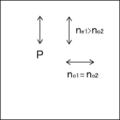
- the refractive index n e1 in the slow axis direction of the optically anisotropic layer is larger than the refractive index n o2 of the isotropic layer, the optically anisotropic layer lagging refractive index n o1 direction perpendicular to the axis is substantially the same as the refractive index n o2 of the isotropic layer.
- the slow axes of the plurality of optically anisotropic layers are laminated so as to be parallel to each other. Accordingly, as shown in FIG. 2, (in FIG.
- the vertical direction is one direction in the in a state in which the refractive index (n e1) is higher layers and the refractive index (n o2) and a lower layer are laminated .
- the refractive index (n e1) is higher layers and the refractive index (n o2) and a lower layer are laminated .
- the direction orthogonal to this one direction left-right direction in FIG. 2
- layers having the same refractive index are laminated.
- a film in which layers having a low refractive index (low refractive index layer) and layers having a high refractive index (high refractive index layer) are alternately laminated has a structural structure between a large number of low refractive index layers and a high refractive index layer. It is known that interference reflects light of a specific wavelength. Therefore, the linearly polarized light reflecting film shown in FIGS. 1 and 2 reflects the linearly polarized light in the vertical direction in FIG. 2 and transmits the linearly polarized light in the left and right direction.
- the reflection spectrum satisfies the above items (i) to (iii).
- the reflected wavelength and the refractive index are adjusted by the refractive index difference, the thickness, the number of layers, etc. between the low refractive index layer and the high refractive index layer. can do.
- the first laminated portion 11 mainly realizes the reflection satisfying the item (i)
- the second laminated portion 12 realizes the reflection satisfying the item (ii)
- the third laminated portion realizes the reflection.
- the part 13 realizes the reflection satisfying the item (iii).
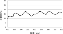
- 3 and 4 show examples of natural light reflection spectra satisfying the above items (i) to (iii).
- the spectrum shown in the graph of FIG. 3 has a first reflection peak near a wavelength of 450 nm.
- the natural light reflectance of this first reflection peak is 10% or more and 20% or less, which satisfies item (i).
- the spectrum shown in the graph of FIG. 3 has a second reflection peak near a wavelength of 530 nm.
- the natural light reflectance of this second reflection peak is 10% or more and 20% or less, which satisfies item (ii).
- the spectrum shown in the graph of FIG. 3 has two third reflection peaks at wavelengths around 640 nm and 700 nm.
- the natural light reflectance of the third reflection peak is 10% or more and 20% or less, respectively, and satisfies item (iii) (a).
- the spectrum shown in the graph of FIG. 4 has a first reflection peak near a wavelength of 460 nm.
- the natural light reflectance of this first reflection peak is 10% or more and 20% or less, which satisfies item (i).
- the spectrum shown in the graph of FIG. 4 has a second reflection peak near a wavelength of 530 nm.
- the natural light reflectance of this second reflection peak is 10% or more and 20% or less, which satisfies item (ii).
- the spectrum shown in the graph of FIG. 4 has a third reflection peak near a wavelength of 690 nm.
- the average value of the maximum value and the minimum value of the reflectance in the band from 600 nm to 800 nm is 16.6%, and the wavelength bandwidth in the region where the reflectance is higher than this is 150 nm.
- the reflection peak is a peak having a maximum value of 2% or more in difference from the adjacent minimum value and a half width of 10 to 200 nm.
- in-vehicle head-up display systems are required to have a transparent appearance color even when viewed from various angles from the viewpoint of transmittance and design that exceed legal regulations.
- it has been considered to reduce the reflectance in order to maintain the transmittance of 70% or more in the regulations and bring the appearance color closer to transparent (white).
- the reflectance is lowered too much, the brightness of the displayed image (projected image) is lowered and the visibility is deteriorated.
- the linearly polarized light reflecting film of the present invention can improve the transparency of color by having a second reflection peak having a reflectance of 10% to 20% at a wavelength of 530 nm or more and less than 600 nm.
- the reflectance of the visual sensitivity around 550 nm is important. Therefore, the transmittance can be ensured by setting the reflectance of the second reflection peak to 20% or less.
- the reflectance near 550 nm in the oblique direction incident angle 60 °
- the linearly polarized reflective film of the present invention has a third reflection peak having a reflectance of 10% to 20% at a wavelength of 600 nm or more and 800 nm or less, and the third reflection peak has two reflection peaks, or a reflection band.
- the width of is 120 nm or more, the front luminance of the displayed image can be improved, and the transparency of the tint when viewed from an oblique direction (incident angle of 60 °) can be improved.
- the front reflection color becomes yellow to red only with the second reflection peak and the third reflection peak.
- the linearly polarized reflective film of the present invention has a first reflection peak having a reflectance of 10% to 20% at a wavelength of 430 nm or more and less than 500 nm, so that the color when viewed from the vicinity of the front surface (incident angle of 5 °).
- the transparency of the taste can be improved.
- a wavelength having low reflectance between the first reflection peak and the second reflection peak and between the second reflection peak and the third reflection peak Since a region is created, the transmittance is improved.
- the natural light transmittance of the windshield glass in which the linearly polarized light reflecting film is sandwiched between green glass can be set to 70% or more (80% or more when the clear glass is sandwiched). Further, the P polarization reflectance can be set to 25% or more, and the brightness of the displayed image can be improved. In addition, the transparency of color when viewed from various directions can be improved.
- the intensity ratio (reflectance ratio) of the first reflection peak and the second reflection peak is 80% or more and 120% or less, and the first reflection peak and the first reflection peak are the first. It is preferable that the intensity ratio of 3 to the reflection peak is 80% or more and 120% or less, and the intensity ratio of the second reflection peak to the third reflection peak is 80% or more and 120% or less.
- the bandwidth of each reflection peak depends on the difference between the refractive index of the optically anisotropic layer in the slow axis direction and the refractive index of the isotropic layer, and the larger the difference in refractive index, the larger the bandwidth. Become. Further, if the reflection peaks having low reflectance are at close wavelengths, they interfere with each other and the reflection peaks become too strong or too weak. Optical anisotropy from the viewpoint of increasing the transmittance while improving the brightness of the displayed image by appropriately adjusting the bandwidth of each reflected peak and reducing the influence of interference with adjacent reflected peaks.
- the difference between the refractive index of the layer in the slow axis direction and the refractive index of the isotropic layer is preferably 0.03 to 0.2, more preferably 0.05 to 0.14. It is more preferably 0.05 to 0.10.
- the wavelength bandwidth of the region where the reflectance is higher than the average value of the maximum value and the minimum value of the reflectance of 430 nm to 500 nm is preferably 20 nm or more and 95 nm or less, and 25 nm or more and 85 nm or less. It is more preferable that it is 30 nm or more and 80 nm or less.
- the wavelength bandwidth of the region where the reflectance is higher than the average value of the maximum value and the minimum value of the reflectance of 530 nm to 600 nm is preferably 20 nm or more and 95 nm or less, and 25 nm or more and 85 nm.
- the wavelength bandwidth of the first reflection peak and the wavelength bandwidth of the second reflection peak are 20 nm or more and 95 nm or less, respectively, that is, the wavelength bandwidths of the first reflection peak and the second reflection peak are narrow. Due to the band, the transmittance can be increased while improving the front luminance of the displayed image.
- the first reflection peak and the second reflection peak are each provided, but even if the first reflection peak and the second reflection peak are each provided by two or more. good.
- the selective reflection layer is composed of two or more light reflection layers having different selective reflection wavelengths, and the light reflection layers having any one of a first reflection peak, a second reflection peak, and a third reflection peak are mutually exclusive. It is preferable that they are in contact with each other.
- a first laminated portion 11 that selectively reflects light having a wavelength of a first reflection peak and a second laminated portion that selectively reflects light having a wavelength of a second reflection peak.
- the second laminated portion 12 which is in contact with each other and selectively reflects the light of the wavelength of the second reflection peak, and the third laminated portion 12 which selectively reflects the light of the wavelength of the third reflection peak.
- the parts 13 are in contact with each other.
- the first laminated portion 11, the second laminated portion 12, and the third laminated portion are the light reflecting layers in the present invention.
- the film thickness between the layers becomes thick and it becomes difficult to obtain the effect of light interference reflected by each light reflecting layer.
- the wavelength bandwidth of each reflected peak can be narrowed due to the effect of the interference of light reflected by each light reflecting layer.
- the linearly polarized light reflective film may be a thin film or a sheet.
- the linearly polarized light reflective film may be in the form of a roll or the like as a thin film before being used for windshield glass.
- the selective reflection layer can be formed by using a wide variety of materials.
- the first material it is necessary for the first material to have a different index of refraction than the second material in the chosen direction.
- This difference in refractive index can be achieved by a variety of methods, including stretching, extrusion, or coating during or after film formation.
- it is preferable to have similar rheological properties eg, melt viscosity
- Materials particularly preferably used as the selective reflective layer include PEN (polyethylene naphthalate) and PET (polyethylene terephthalate) as the optically anisotropic layer, and (isotropically adjusted) as the isotropic layer. ) PEN, PET and PMMA (polymethylmethacrylate resin).
- the linearly polarized light reflection film (selective reflection layer) of the present invention has an optically anisotropic layer and the like so as to have a configuration having a first reflection peak, a second reflection peak and a third reflection peak. It has three laminated parts with different thicknesses of the anisotropic layer.
- each of the three laminated portions may be formed by the above-mentioned stretching, extrusion molding, or the like, and then the laminated portions may be laminated to produce a linearly polarized light reflecting film.
- the thickness before processing may be adjusted so that the three laminated portions having different thicknesses are formed, and the three laminated portions may be integrally formed by stretching, extrusion molding, or the like.
- the thickness of the selective reflective layer is preferably in the range of 2.0 to 50 ⁇ m, more preferably in the range of 8.0 to 30 ⁇ m.
- the linearly polarized light reflective film has a selective reflective layer.
- the linearly polarized light-reflecting film may have a configuration including a retardation layer, a polarization conversion layer, a support, an adhesive layer, and the like in addition to the selective reflection layer.
- the support, the adhesive layer, and the like are both transparent in the visible light region. Further, it is preferable that both the support and the adhesive layer have low birefringence.
- the low birefringence means that the front phase difference is 10 nm or less in the wavelength range in which the linearly polarized light reflecting film of the windshield glass of the present invention exhibits reflection. This front phase difference is preferably 5 nm or less. Further, it is preferable that the difference in the refractive index from the average refractive index (in-plane average refractive index) of the selective reflection layer is small for both the support and the adhesive layer.
- the support can also be used as a substrate when forming the selective reflection layer.
- the support used for forming the selective reflection layer may be a temporary support that is peeled off after the formation of the selective reflection layer. Therefore, the finished linearly polarized reflective film and windshield glass may not include a support.
- the support is preferably transparent in the visible light region.
- the support there are no restrictions on the material of the support.
- the support include polyesters such as polyethylene terephthalate (PET), polycarbonates, acrylic resins, epoxy resins, polyurethanes, polyamides, polyolefins, cellulose derivatives, and plastic films such as silicones.
- PET polyethylene terephthalate
- acrylic resins acrylic resins
- epoxy resins epoxy resins
- polyurethanes polyamides
- polyolefins polyolefins
- cellulose derivatives cellulose derivatives
- plastic films such as silicones.
- glass may be used in addition to the above-mentioned plastic film.
- the thickness of the support may be about 5.0 to 1000 ⁇ m, preferably 10 to 250 ⁇ m, and more preferably 15 to 90 ⁇ m.
- the windshield glass having the linearly polarized light reflecting film of the present invention and the head-up display (HUD) will be described.
- Winddshield glass> By using the linearly polarized light reflective film of the present invention, it is possible to provide a windshield glass having a projected image display function.
- Windshield glass means windows and windshields for vehicles such as cars and trains, airplanes, ships, two-wheeled vehicles, and general vehicles such as playsets.
- the windshield glass is preferably used as a windshield, a windshield, or the like in front of the vehicle in the traveling direction.
- the visible light transmittance of the windshield glass is preferably 70% or more, more preferably more than 70%, further preferably 75% or more, and particularly preferably 80% or more.
- the above-mentioned visible light transmittance is preferably satisfied at any position of the windshield glass, and particularly preferably the above-mentioned visible light transmittance is satisfied at the position where the linearly polarized light reflecting film is present. ..
- the linearly polarized light-reflecting film of the present invention has a high visible light transmittance, so that the above-mentioned visible light transmittance is satisfied regardless of which glass is generally used for the windshield glass. Can be.
- the windshield glass may be, for example, a flat surface or a three-dimensional shape having a curved surface such as a concave surface or a convex surface.
- the upward direction during normal use, the observer side, the driver side, and the visible side surface such as the inside of the vehicle can be specified.
- the windshield glass may have a uniform thickness or a non-uniform thickness at the portion where the linearly polarized light reflecting film is arranged.
- it may have a wedge-shaped cross-sectional shape like the vehicle glass described in Japanese Patent Application Laid-Open No. 2011-505330 and the thickness of the linearly polarized light reflecting film may be non-uniform, but the linearly polarized light reflecting film is arranged. It is preferable that the thickness is uniform in the portion.
- the linearly polarized light reflecting film may be provided at the projected image display portion (projected image reflecting portion) of the windshield glass.
- Head-up using windshield glass by providing the linearly polarized reflective film of the present invention on the outer surface of the glass plate of windshield glass, or by providing it between the glass of windshield glass having a laminated glass structure as described later.
- a display hereinafter, also referred to as HUD can be configured.
- the linearly polarized light reflecting film of the present invention When the linearly polarized light reflecting film of the present invention is provided on the outer surface of the glass plate of the windshield glass, the linearly polarized light reflecting film may be provided inside the vehicle or the like (incident side of the projected image) or outside. However, it is preferable that it is provided inside.
- the linearly polarized light reflective film of the present invention has lower scratch resistance than a glass plate. Therefore, when the windshield glass has a laminated glass structure, it is more preferable that the linearly polarized reflective film is provided between the two pieces of glass constituting the laminated glass in order to protect the linearly polarized reflective film.
- the linearly polarized light reflecting film is a member for displaying a projected image by reflecting the projected image. Therefore, the linearly polarized light-reflecting film may be provided at a position where the projected image projected from the projector or the like can be visually displayed. That is, the linearly polarized light reflective film of the present invention functions as a combiner of the HUD.
- the combiner can visually display the image projected from the projector, and when the combiner is observed from the incident surface side of the projected image, the surface opposite to the incident surface of the projected light such as a landscape. It means an optical member capable of observing information on the side at the same time. That is, the combiner has a function as an optical path combiner that superimposes and displays the outside world light and the light of the projected image.
- the linearly polarized light reflective film may be provided on the entire surface of the windshield glass, or may be provided on a part of the windshield glass in the plane direction, but it is preferable that the linearly polarized light reflective film is provided on a part of the windshield glass.
- the linearly polarized light reflecting film may be provided at any position on the windshield glass, but when used as a HUD, it is easily visible to an observer such as a driver. It is preferably provided so that a virtual image is shown at the position.
- the position where the linearly polarized light reflecting film is provided on the windshield glass may be determined from the relationship between the position of the driver's seat in the vehicle on which the HUD is mounted and the position where the projector is installed.
- the linearly polarized light reflecting film may have a flat surface having no curved surface, but may have a curved surface.
- the linearly polarized light-reflecting film may have a concave or convex shape as a whole, and the projected image may be enlarged or reduced for display.
- the windshield glass may have a laminated glass structure.
- the windshield glass of the present invention is a laminated glass, and has the linearly polarized light reflecting film of the present invention described above between the first glass plate and the second glass plate.
- the windshield glass may have a configuration in which a linearly polarized light reflecting film is arranged between the first glass plate and the second glass plate.
- the windshield glass is provided with an interlayer film (intermediate film sheet) between the first glass plate and the linearly polarized light reflecting film and between the linearly polarized light reflecting film and the second glass plate on at least one of them. It is preferable that the configuration is as follows.
- the first glass plate is arranged on the side opposite to the viewing side (outside the vehicle) of the image in the HUD, and the second glass plate is arranged on the viewing side (inside the vehicle).
- the first and second glass plates in the first glass plate and the second glass plate have no technical meaning, and for convenience in order to distinguish between the two glass plates. It is provided. Therefore, the first glass plate may be on the inside of the vehicle and the second glass plate may be on the outside of the vehicle.
- a glass plate generally used for windshield glass can be used as the glass plate such as the first glass plate and the second glass plate.
- a glass plate having a visible light transmittance of 73%, 76%, or less of 80% or less such as green glass having high heat shielding property, may be used. Even when a glass plate having such a low visible light transmittance is used, by using the linearly polarized light reflecting film of the present invention, the visible light transmittance of 70% or more can be achieved even at the position of the linearly polarized light reflecting film. A windshield glass having can be produced.
- the thickness of the glass plate is not particularly limited, but may be about 0.5 to 5.0 mm, preferably 1.0 to 3.0 mm, and more preferably 2.0 to 2.3 mm.
- the materials or thicknesses of the first glass plate and the second glass plate may be the same or different.
- the windshield glass having a laminated glass structure can be produced by using a known laminated glass manufacturing method. Generally, after sandwiching an interlayer film for laminated glass between two glass plates, heat treatment and pressure treatment (treatment using a rubber roller, etc.) are repeated several times, and finally an autoclave or the like is used. It can be produced by a method of performing heat treatment under pressurized conditions.
- the windshield glass having a structure of a laminated glass having a linearly polarized reflective film and an interlayer film may be produced by the above-mentioned method for producing a laminated glass after forming a linearly polarized reflective film on the surface of a glass plate.
- it may be produced by the above-mentioned method for producing a laminated glass by using an interlayer film for a laminated glass containing the above-mentioned linearly polarized light-reflecting film.
- the glass plate on which the linearly polarized light reflecting film is provided may be either a first glass plate or a second glass plate. At this time, the linearly polarized light reflecting film is bonded to, for example, a glass plate with an adhesive.
- interlayer film As the interlayer film (intermediate film sheet), any known interlayer film used as an intermediate film (intermediate layer) in laminated glass can be used.
- a resin film containing a resin selected from the group of polyvinyl butyral (PVB), ethylene-vinyl acetate copolymer and chlorine-containing resin can be used.
- the above-mentioned resin is preferably the main component of the interlayer film.
- the main component means a component that occupies 50% by mass or more of the interlayer film.
- polyvinyl butyral and ethylene-vinyl acetate copolymer are preferable, and polyvinyl butyral is more preferable.
- the resin is preferably a synthetic resin.
- Polyvinyl butyral can be obtained by acetalizing polyvinyl alcohol with butyraldehyde.
- the preferred lower limit of the degree of acetalization of polyvinyl butyral described above is 40%, the preferred upper limit is 85%, the more preferred lower limit is 60%, and the more preferred upper limit is 75%.
- Polyvinyl alcohol is usually obtained by saponifying polyvinyl acetate, and polyvinyl alcohol having a saponification degree of 80 to 99.8 mol% is generally used. Further, the preferable lower limit of the degree of polymerization of the above-mentioned polyvinyl alcohol is 200, and the preferable upper limit is 3000. When the degree of polymerization of polyvinyl alcohol is 200 or more, the penetration resistance of the obtained laminated glass is unlikely to decrease, and when it is 3000 or less, the moldability of the resin film is good and the rigidity of the resin film does not become too large. Good workability. A more preferred lower limit is 500 and a more preferred upper limit is 2000.
- the interlayer film for laminated glass including the linearly polarized light reflecting film can be formed by laminating the linearly polarized light reflecting film on the surface of the above-mentioned interlayer film.
- the linearly polarized light-reflecting film can be formed by sandwiching it between the two above-mentioned interlayer films.
- the two interlayer films may be the same or different, but are preferably the same.
- a known bonding method can be used for bonding the linearly polarized light reflecting film and the interlayer film, but it is preferable to use a laminating process.
- the laminating treatment is preferably carried out under certain heating and pressurizing conditions so that the laminated body and the interlayer film do not peel off after processing.
- the film surface temperature on the side where the interlayer film is adhered is preferably 50 to 130 ° C, more preferably 70 to 100 ° C. It is preferable to pressurize at the time of laminating.
- the pressurizing conditions are not limited, but less than 2.0 kg / cm 2 (less than 196 kPa) is preferable, 0.5 to 1.8 kg / cm 2 (49 to 176 kPa) is more preferable, and 0.5 to 1.5 kg. / Cm 2 (49-147 kPa) is even more preferred.
- the support When the linearly polarized light reflective film has a support, the support may be peeled off at the same time as laminating, immediately after laminating, or immediately before laminating. That is, the linearly polarized light-reflecting film attached to the interlayer film obtained after laminating may not have a support.
- An example of a method for producing an interlayer film including a linearly polarized light reflecting film is (1) The first step of laminating a linearly polarized light reflecting film on the surface of the first interlayer film to obtain a first laminate, and (2) The second step of laminating the second interlayer film on the surface opposite to the surface to which the first interlayer film of the linearly polarized light reflecting film in the first laminated body is bonded is included. ..
- the linearly polarized light reflecting film and the first interlayer film are bonded together without facing each other between the support and the first interlayer film.
- the support is then stripped from the linearly polarized reflective film.
- the second interlayer film is attached to the surface from which the support has been peeled off. This makes it possible to manufacture an interlayer film containing a linearly polarized light reflecting film having no support.
- the interlayer film containing the linearly polarized light reflecting film it is possible to easily produce a laminated glass in which the linearly polarized light reflecting film does not have a support.
- the temperature of the support when the support is peeled from the linearly polarized light reflective film is preferably 40 ° C. or higher, more preferably 40 to 60 ° C.
- the windshield glass can be used as a component of the HUD.
- the HUD preferably includes a projector.
- a "projector” is a “device that projects light or an image”, includes a “device that projects a drawn image”, and emits projected light that carries an image to be displayed.
- the projector emits p-polarized projected light.
- the projector may be arranged so that the projected light of p-polarized light carrying the image to be displayed can be incident on the linearly polarized light reflecting film in the windshield glass at an oblique incident angle.
- the projector includes a drawing device and reflects and displays an image (real image) drawn on a small intermediate image screen as a virtual image by a combiner.
- a known projector used for the HUD can be used as long as it can emit the projected light of p-polarized light.
- the projector has a variable imaging distance of the virtual image, that is, the imaging position of the virtual image.
- Examples of the method of changing the imaging distance of a virtual image in a projector include a method of moving an image generation surface (screen) (see Japanese Patent Application Laid-Open No. 2017-21302) and a method of switching between a plurality of optical paths having different optical path lengths. (See WO2015 / 190157), a method of changing the optical path length by inserting and / or moving a mirror, a method of changing the focal distance using a group lens as an imaging lens, a method of moving the projector 22, a virtual image imaging method. Examples thereof include a method of switching and using a plurality of projectors having different distances, a method of using a variable focus lens (see WO2010 / 116912), and the like.
- the projector may be one in which the imaging distance of the virtual image can be continuously changed, or one in which the imaging distance of the virtual image can be switched at two points or a plurality of points of three or more points.
- the imaging distance of the virtual image can be switched at two points or a plurality of points of three or more points.
- the virtual images of the projected light by the projector it is preferable that at least two virtual images have different imaging distances of 1 m or more. Therefore, when the projector can continuously change the imaging distance of the virtual image, it is preferable that the imaging distance of the virtual image can be changed by 1 m or more. It is preferable to use such a projector in that it can be suitably used even when the distance of the driver's line of sight is significantly different, such as when traveling at a normal speed on a general road and when traveling at a high speed on an expressway. ..
- the drawing device itself may be a device that displays an image, or may be a device that emits light capable of drawing an image.
- the light from the light source may be adjusted by a drawing method such as an optical modulator, a laser luminance modulation means, or a light deflection means for drawing.
- the drawing device means a device including a light source and further including a light modulator, a laser luminance modulation means, a light deflection means for drawing, and the like depending on the drawing method.
- the light source is not limited, and known light sources such as LEDs (light emitting diodes), organic light emitting diodes (OLEDs), discharge tubes, and laser light sources used in projectors, drawing devices, displays, and the like can be used.
- LEDs and discharge tubes are preferable because they are suitable as a light source for a drawing device that emits linearly polarized light, and LEDs are particularly preferable. This is because the emission wavelength of the LED is not continuous in the visible light region, and therefore, as will be described later, the LED is suitable for combination with a combiner in which a cholesteric liquid crystal layer exhibiting selective reflection in a specific wavelength region is used.
- the drawing method can be selected according to the light source to be used and the like, and is not particularly limited. Examples of drawing methods include a fluorescent display tube, an LCD (Liquid Crystal Display) method that uses a liquid crystal display, an LCOS (Liquid Crystal on Silicon) method, a DLP (registered trademark) (Digital Light Processing) method, and a laser. A scanning method and the like can be mentioned.
- the drawing method may be a method using a fluorescent display tube integrated with a light source.
- the LCD method is preferable as the drawing method.
- the DLP method is a display system using a DMD (Digital Micromirror Device), and is drawn by arranging micromirrors for the number of pixels and emitting light from a projection lens.
- DMD Digital Micromirror Device
- the scanning method is a method in which light rays are scanned on a screen and contrast is performed using the afterimage of the eyes.
- the descriptions in JP-A-7-270711 and JP-A-2013-228674 can be referred to.
- brightness-modulated laser light of each color for example, red light, green light, and blue light
- the light beam is light. It suffices that it is scanned by the deflection means and drawn on the intermediate image screen described later.
- the brightness modulation of the laser light of each color of red light, green light, and blue light may be performed directly as a change in the intensity of the light source, or may be performed by an external modulator.
- the light deflection means include a galvano mirror, a combination of a galvano mirror and a polygon mirror, and a MEMS (Micro Electro Mechanical Systems), of which MEMS is preferable.
- the scanning method include a random scan method and a raster scan method, but it is preferable to use the raster scan method.
- the laser beam can be driven by, for example, a resonance frequency in the horizontal direction and a sawtooth wave in the vertical direction. Since the scanning method does not require a projection lens, the device can be easily miniaturized.
- the light emitted from the drawing device may be linearly polarized light or natural light (non-polarized light).
- the drawing method is an LCD method or an LCOS method and a drawing device using a laser light source
- the emitted light is essentially linearly polarized light.
- the polarization directions (transmission axis direction) of the light having a plurality of wavelengths are the same.
- the drawing device may use an intermediate image screen.
- the "intermediate image screen” is a screen on which an image is drawn. That is, when the light emitted from the drawing device is not yet visible as an image, the drawing device forms a visible image on the intermediate image screen by this light.
- the image drawn on the intermediate image screen may be projected on the combiner by the light transmitted through the intermediate image screen, or may be reflected on the intermediate image screen and projected on the combiner.
- intermediate image screens include a scattering film, a microlens array, a screen for rear projection, and the like.
- a plastic material is used as the intermediate image screen
- the intermediate image screen has birefringence, the polarizing plane and the light intensity of the polarized light incident on the intermediate image screen are disturbed, and the color in the combiner (linearly polarized light reflecting film) is disturbed.
- unevenness and the like are likely to occur, the problem of color unevenness can be reduced by using a retardation film having a predetermined retardation.
- the intermediate image screen preferably has a function of spreading and transmitting incident light rays. This is because the projected image can be enlarged and displayed. Examples of such an intermediate image screen include a screen composed of a microlens array.
- the microarray lens used in the HUD is described in, for example, Japanese Patent Application Laid-Open No. 2012-226303, Japanese Patent Application Laid-Open No. 2010-145745, and Japanese Patent Application Laid-Open No. 2007-523369.
- the projector may include a reflector or the like that adjusts the optical path of the projected light formed by the drawing device.
- JP-A-2-141720, JP-A-10-96874, JP-A-2003-98470, US Pat. No. 5,013,134, and Japanese Patent Application Laid-Open No. 5013134, and Japanese Patent Application Laid-Open No. Table 2006-512622, etc. can be referred to.
- Windshield glass is particularly useful for HUDs that use lasers, LEDs, OLEDs (organic light emitting diodes), etc., whose emission wavelength is not continuous in the visible light region, in combination with a projector as a light source. This is because the center wavelength of the selective reflection of the cholesteric liquid crystal layer can be adjusted according to each emission wavelength. It can also be used for projection of a display such as an LCD (liquid crystal display) in which the display light is polarized.
- LCD liquid crystal display
- the incident light is preferably incident at an oblique incident angle of 45 ° to 70 ° with respect to the normal of the linearly polarized light reflecting film.
- the Brewster angle at the interface between glass with a refractive index of about 1.51 and air with a refractive index of 1 is about 56 °, and by incident p-polarized light within the above angle range, incident light for displaying projected images is used. It is possible to display an image in which the amount of reflected light from the surface of the windshield glass on the visual side is small with respect to the selective reflective layer of the above, and the influence of the double image is small.
- the above-mentioned angle is also preferably 50 ° to 65 °.
- the projected image may be observed at an angle of 45 ° to 70 °, preferably 50 ° to 65 ° on the incident side of the projected light and on the opposite side of the normal line of the selective reflection layer to the incident light. Any configuration can be used.
- the incident light may be incident from any direction such as up, down, left and right of the windshield glass, and may be determined in correspondence with the viewing direction. For example, it is preferable to use a configuration in which the light is incident at an oblique angle of incidence as described above from the lower direction during use. Further, the linearly polarized light reflecting film of the windshield glass may be arranged so as to reflect the incident p-polarized light.
- the projected light at the time of displaying the projected image in the HUD of the present invention is p-polarized light that vibrates in the direction parallel to the incident surface.
- a linearly polarizing film (polarizer) may be provided on the emitted light side of the projector to obtain p-polarized light, and the linearly polarized film may be provided in the optical path from the projector to the windshield glass. Etc. may be used as p-polarized light by a known method.
- a member that converts projected light that is not linearly polarized light into p-polarized light is also considered to constitute the projector in the HUD of the present invention.
- the polarization directions of the emitted light in the red, green, and blue wavelength ranges are not uniform, the polarization directions are adjusted in a wavelength-selective manner and used as p-polarized light in all color wavelength ranges. It is preferable to make it incident.
- the HUD may be a projection system in which the virtual image imaging position is variable.
- the virtual image imaging position is a position where the virtual image can be visually recognized from the driver of the vehicle, for example, a position 1000 mm or more away from the tip of the windshield glass when viewed from the normal driver.
- the glass is non-uniform (wedge-shaped) in the linearly polarized light-reflecting film as described in Japanese Patent Publication No. 2011-505330 described above, the angle of the wedge-shaped image is also changed when the virtual image imaging position is changed. Need to be done. Therefore, for example, as described in Japanese Patent Application Laid-Open No.
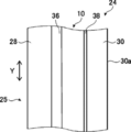
- FIG. 5 is a schematic view showing an example of a head-up display having a linearly polarized light reflecting film according to an embodiment of the present invention
- FIG. 6 shows an example of a windshield glass having a linearly polarized light reflecting film according to the embodiment of the present invention.
- the HUD 20 has a projector 22 and a windshield glass 24, and is used for a vehicle such as a passenger car, for example.
- the components of the HUD 20 have already been described.
- the windshield glass 24 includes a first glass plate 28 which is a first glass plate, a second glass plate 30 which is a second glass plate, and linear polarization reflection. It has a film 10, an interlayer film 36, and an adhesive layer 38.
- the linearly polarized light reflecting film 10 is the linearly polarized light reflecting film 10 shown in FIG. 1, and has a selective reflecting layer in which optically anisotropic layers and isotropic layers are alternately laminated.
- the vertical direction Y of the windshield glass 24 and the axis P of the linearly polarized light reflecting film 10 shown in FIG. 2 are aligned with each other.
- the linearly polarized light reflective film may have a support.
- the vertical direction Y of the windshield glass 24 is a direction corresponding to the top-bottom direction of the vehicle or the like on which the windshield glass 24 is arranged, and is defined as the ground side as the lower side and the opposite side as the upper side.
- the vertical direction Y is on the surface 25 of the windshield glass 24. It will be in the direction along.
- the surface 25 is the outer surface side of the vehicle.
- the projector 22 is as described above.
- a known projector used for the HUD can be used as long as it can emit p-polarized projected light on which the image to be displayed is supported.
- the projector 22 preferably has a variable imaging distance of the virtual image, that is, an imaging position of the virtual image.
- the projector 22 irradiates the windshield glass 24 (second glass plate 30) with the projected light of p-polarized light.
- the reflection of the projected light by the second glass plate 30 and the first glass plate 28 of the windshield glass 24 is significantly reduced, and the reflection is doubled. Inconveniences such as observing an image can be suppressed.
- the projector 22 irradiates the windshield with p-polarized projected light at a Brewster's angle. As a result, the reflection of the projected light on the second glass plate 30 and the first glass plate 28 is eliminated, and a clearer image can be displayed.
- the windshield glass 24 is a so-called laminated glass, and has an interlayer film 36, a linearly polarized light-reflecting film 10, and an adhesive layer 38 between the first glass plate 28 and the second glass plate 30.
- the projected light emitted by the projector 22 is incident from the surface 30a of the second glass plate 30.
- the linearly polarized light reflecting film 10 reflects p-polarized light, and as described above, the axis P shown in FIG. 2, that is, the direction of linearly polarized light reflected by the linearly polarized light reflecting film is set so as to reflect p-polarized light. NS.
- the linearly polarized light reflecting film 10 has a first reflection peak, a second reflection peak, and a third reflection peak as reflection characteristics.
- the linearly polarized light reflective film 10 is attached to the first glass plate 28 by the interlayer film 36, and is attached to the second glass plate 30 by the adhesive layer 38, and the first glass plate 28 and the second glass plate 30 are attached to each other. It is sandwiched between them.
- the first glass plate 28 and the second glass plate 30 of the windshield glass 24 are basically provided in parallel.
- the first glass plate 28 and the second glass plate 30 are both known glasses (glass plates) used for windshields of vehicles and the like. Therefore, the forming material, thickness, shape, etc. may be the same as the glass used for known windshields.
- the first glass plate 28 and the second glass plate 30 shown in FIG. 6 are both flat plates, but the present invention is not limited to this, and a part thereof may be a curved surface or the entire surface may be a curved surface.
- the interlayer film 36 prevents the glass from penetrating into the vehicle and scattering in the event of an accident, and further adheres the linearly polarized light reflecting film 10 and the first glass plate 28.
- a known interlayer film (intermediate layer) used for the windshield of laminated glass can be used.
- the material for forming the interlayer film 36 include polyvinyl butyral (PVB), ethylene-vinyl acetate copolymer, chlorine-containing resin, and polyurethane.
- the thickness of the interlayer film 36 is not limited, and the thickness according to the forming material or the like may be set in the same manner as the known interlayer film of windshield glass.
- the adhesive layer 38 is, for example, a layer made of a coating type adhesive.
- the linearly polarized light reflective film 10 is attached to the second glass plate 30 by the adhesive layer 38.
- the linearly polarized light reflecting film 10 may be attached to the second glass plate 30 by an interlayer film instead of the adhesive layer 38.
- the intermediate film 36 is used to attach the linearly polarized light reflecting film 10 to the second glass. It may be attached to the board 30.
- the adhesive layer 38 is known as long as it has no limitation, can secure the transparency required for the windshield glass 24, and can adhere the linearly polarized light reflective film 10 and the glass with the necessary adhesive force.
- Various coating type adhesives are available.
- the adhesive layer 38 may be the same as the interlayer film 36 such as PVB. In addition to this, an acrylate-based adhesive or the like can also be used for the adhesive layer 38. Further, as the adhesive layer 38, the same adhesive layer as the above-mentioned adhesive layer may be used as shown below.
- the adhesive layer 38 may be formed of an adhesive in the same manner as the above-mentioned adhesive layer.
- the adhesive includes a hot melt type, a thermosetting type, a photocuring type, a reaction curing type, and a pressure-sensitive adhesive type that does not require curing.
- the adhesives of any type are acrylate-based, urethane-based, urethane acrylate-based, epoxy-based, epoxy acrylate-based, polyolefin-based, modified olefin-based, polypropylene-based, ethylene vinyl alcohol-based, vinyl chloride-based, respectively.
- Compounds such as chloroprene rubber-based, cyanoacrylate-based, polyamide-based, polyimide-based, polystyrene-based, and polyvinyl butyral-based compounds can be used.
- the photocurable type is preferable as the curing method, and from the viewpoint of optical transparency and heat resistance, acrylate-based, urethane acrylate-based, epoxy acrylate-based, etc. may be used as the material. preferable.
- the adhesive layer 38 may be formed by using a highly transparent adhesive transfer tape (OCA tape).
- OCA tape a commercially available product for an image display device, particularly a commercially available product for the surface of an image display portion of an image display device may be used.
- Examples of commercially available products include adhesive sheets manufactured by Panac Co., Ltd. (PD-S1 and the like), adhesive sheets of the MHM series manufactured by Niei Kako Co., Ltd., and the like.
- the thickness of the adhesive layer 38 there is no limitation on the thickness of the adhesive layer 38. Therefore, the thickness at which sufficient adhesive force can be obtained may be appropriately set according to the material for forming the adhesive layer 38.
- the thickness of the adhesive layer 38 is preferably 0.1 to 800 ⁇ m, more preferably 0.5 to 400 ⁇ m.
- the windshield glass 24 is provided with an adhesive layer 38 between the linearly polarized light reflecting film 10 and the second glass plate 30, and the linearly polarized light reflecting film 10 and the first glass plate 28 are attached by an interlayer film 36.
- an adhesive layer may be provided between the linearly polarized light reflecting film 10 and the first glass plate 28, and an intermediate film may be provided between the linearly polarized light reflecting film 10 and the second glass plate 30.
- the windshield glass 24 does not have an interlayer film 36, and the linearly polarized light reflecting film 10 and the first glass plate 28 are attached to each other, and the linearly polarized light reflecting film 10 and the second glass plate 30 are attached to each other.
- the structure may be such that the adhesive layer 38 is used.
- the windshield glass 24 has a linearly polarized light-reflecting film 10 between the first glass plate 28 and the second glass plate 30, and the adhesive layer 38 attaches the linearly-polarized reflective film 10 to the second glass plate 30. It has a structure in which the linearly polarized light-reflecting film 10 is attached to the first glass plate 28 by the interlayer film 36.
- the image observer that is, the driver D, observes the virtual image of the projected image by the projector 22 projected by the projector 22 and reflected by the windshield glass 24.
- the projected image of the projector is reflected by the glass of the windshield, and the reflected light is observed.
- a general windshield is a laminated glass and has two pieces of glass, an inner surface side and an outer surface side. Therefore, in the HUD, there is a problem that a double image is observed by the driver due to the reflected light of the two glasses.
- the cross-sectional shape of the windshield is made wedge-shaped so that the reflection of the inner glass and the reflection of the outer glass overlap, and the double image cannot be seen. I am trying to do it.
- the wedge-shaped windshield for example, when the imaging distance of the virtual image is changed in order to cope with the difference in the driver's line of sight between normal driving where the line of sight is close and high-speed driving where the line of sight is far away. , The angle of the wedge of the windshield does not match, and the image observed by the driver becomes a double image.
- the projector 22 projects p-polarized light
- the windshield glass 24 reflects p-polarized light between the first glass plate 28 and the second glass plate 30.
- the driver D observes the reflected light by the linearly polarized light reflecting film 10.
- the reflection of the projected light of the projector 22 is basically dominated by the reflection of the linearly polarized light reflecting film 10, so that a double image is basically unlikely to occur.
- the HUD 20 using the linearly polarized light reflecting film 10 of the present invention for the windshield glass 24 it is not necessary to make the cross-sectional shape of the windshield glass 24 (intermediate film 36) a wedge shape, and therefore, the imaging distance of the virtual image is changed. However, no double image is generated.
- the present invention is basically configured as described above.
- the linearly polarized reflective film, the windshield glass, and the head-up display system (HUD) of the present invention have been described in detail above, but the present invention is not limited to the above-described embodiment, and the present invention is not limited to the above-described embodiment and does not deviate from the gist of the present invention. Of course, various improvements or changes may be made.
- Example 1 ⁇ Manufacturing of linearly polarized light reflective film> A linearly polarized light reflecting film (selective reflective layer) was produced as follows based on the method described in Japanese Patent Publication No. 9-506837.
- PEN 2,6-Polyethylene naphthalate
- coPEN copolyester
- naphthalate 70 / terephthalate 30 2,6-Polyethylene naphthalate
- PEN and coPEN single layer films After extrusion molding of PEN and coPEN single layer films, they were stretched at about 150 ° C. at a stretching ratio of 5: 1 and heat-treated at about 230 ° C. for 30 seconds. It was confirmed that the refractive index of PEN with respect to the slow axis (orientation axis) was about 1.86, the refractive index with respect to the transverse axis was 1.64, and the refractive index of the coPEN film was about 1.64.
- the refractive index of PEN with respect to the slow-phase axis is about 1.71
- the refractive index with respect to the transverse axis is 1.64
- the refractive index of the coPEN film is about 1.64. confirmed. That is, the difference ⁇ n between the refractive index of the optically anisotropic layer in the slow axis direction and the refractive index of the isotropic layer is 0.07.
- the stretched laminate was heat-treated in an air oven at about 230 ° C. for 30 seconds to prepare a linearly polarized light-reflecting film.
- the thickness of the produced linearly polarized light reflecting film was about 10 ⁇ m.
- Examples 2 to 4, Comparative Examples 1 to 3 The refractive index of the PEN layer in the slow axis direction, that is, the difference between the refractive index of the optically anisotropic layer in the slow axis direction and the refractive index of the isotropic layer ⁇ n, the PEN layer (optically anisotropic layer) and coPEN.
- the film thickness and the number of layers of the layers (in the slow axis direction) were appropriately changed to prepare a linearly polarized reflective film having the reflection peaks shown in Table 2 below.
- Table 2 below shows the wavelengths, reflectances, wavelength bands, and the presence or absence of contact between the light reflecting layers of the reflected peaks of each example and comparative example. In Table 2, when there are a plurality of third reflection peaks, each reflection peak is distinguished as a third A, a third B, a third C, and a third D.
- the intensity ratio of the first reflection peak, the second reflection peak, and the third reflection peak is 80% or more and 120% or less.
- the intensity ratio of the first reflection peak to the second reflection peak is 150%, and the intensity ratio of the first reflection peak to the third reflection peak is 125%.
- the reflectance and the wavelength bandwidth at each reflection peak in each Example and Comparative Example were measured as follows.
- the produced linearly polarized light-reflecting film was attached to the front surface of the glass plate, and a black PET film (light absorber) was attached to the back surface of the glass plate.
- a spectrophotometer manufactured by JASCO Corporation, V-670
- P-polarized light and S-polarized light are incident from the surface of the linearly polarized light-reflecting film from a direction of 5 ° to the normal direction, respectively, and reflected from 400 nm to 1000 nm.
- the spectra were measured respectively.
- the average value (average reflection spectrum) of the measured P-polarized light reflection spectrum and S-polarized light reflection spectrum was obtained.
- the average value of the reflectance when P-polarized light is incident and the reflectance when S-polarized light is incident is synonymous with the reflectance when unpolarized light (natural light) is incident. That is, the average value of the P-polarized light reflection spectrum and the S-polarized light reflection spectrum is synonymous with the reflection spectrum when natural light is incident.
- the reflection peak (maximum value) in the wavelength band of 430 nm to 500 nm is extracted as the first reflection peak, and its reflectance and wavelength bandwidth are calculated.
- the reflection peak (maximum value) in the wavelength band of 530 nm to 600 nm is extracted as the second reflection peak, and its reflectance and wavelength bandwidth are calculated.
- the reflection peak (maximum value) in the band of wavelength 600 nm to 800 nm was extracted as the third reflection peak, and the number of peaks, the reflectance and the wavelength bandwidth were calculated.
- the wavelength bandwidth of the first reflection peak is the width of a region where the reflectance is higher than the average value of the maximum value and the minimum value of the reflectance in the band having a wavelength of 430 nm to 500 nm.
- the wavelength bandwidth of the second reflection peak is the width of a region where the reflectance is higher than the average value of the maximum value and the minimum value of the reflectance in the band having a wavelength of 530 nm to 600 nm.
- the wavelength bandwidth of the third reflection peak is the width of a region where the reflectance is higher than the average value of the maximum value and the minimum value of the reflectance in the band having a wavelength of 600 nm to 800 nm.
- the first reflection peak and the second reflection peak overlap each other, and the wavelength bandwidth extends from a region having a wavelength of 430 nm to 500 nm to a region having a wavelength of 530 nm to 600 nm.
- the windshield glass having each linearly polarized light reflecting film produced above was produced as follows.
- a glass plate (manufactured by Central Glass Co., Ltd., FL2, visible light transmittance 90%) having a length of 120 mm, a width of 100 mm, and a thickness of 2 mm was prepared.
- a PVB film was placed as an interlayer film having a thickness of 0.38 mm manufactured by Sekisui Chemical Co., Ltd., which was cut to the same size.
- a sheet-shaped linearly polarized light-reflecting film cut into a size of 110 mm in length ⁇ 90 mm in width was placed on the interlayer film with the slow phase axial direction aligned with the vertical direction.
- a glass plate (manufactured by Central Glass Co., Ltd., FL2, visible light transmittance 90%) having a length of 120 mm, a width of 100 mm, and a thickness of 2 mm was placed on the linearly polarized light-reflecting film.
- This laminate was held at 90 ° C. and 10 kPa (0.1 atm) for 1 hour, and then heated in an autoclave (manufactured by Kurihara Seisakusho) at 115 ° C. and 1.3 MPa (13 atm) for 20 minutes to remove air bubbles. , Obtained a windshield glass.
- the projected image reflectance was calculated by multiplying the reflectance by a coefficient corresponding to the visual sensitivity and the emission spectrum of the D65 light source at wavelengths of every 10 nm from 380 to 780 nm, and evaluated as brightness.
- the brightness was evaluated according to the following evaluation criteria.
- the examples give better results in terms of transmittance, P-polarized reflectance (luminance), and reflected tint as compared with the comparative examples.
- the difference ⁇ n between the refractive index of the optically anisotropic layer in the slow axis direction and the refractive index of the isotropic layer is preferably 0.05 to 0.14, and is 0. It can be seen that it is more preferably 0.05 to 0.10.
- the intensity ratio of each reflected peak is preferably 80% or more and 120% or less. From the above results, the effect of the present invention is clear.
- HUD head-up display system
Abstract
The present invention provides a linearly polarized light reflection film having high visible light transmittance, capable of increasing brightness of a display image, and having good transparency of tone of appearance, a windshield glass, and a head-up display system. This linearly polarized light reflection film has a selective reflection layer formed by stacking an optically anisotropic layer and an isotropic layer. The selective reflection layer has at least one first reflection peak with a central reflection wavelength of 430 nm or longer but less than 500 nm, has at least one second reflection peak with a reflectance of 10-20% and a central reflection wavelength of 530 nm or longer but less than 600 nm, and has a third reflection peak with a reflectance of 10-20% and a central reflection wavelength of 600-800 nm, the third reflection peak having two or more reflection peaks with a reflectance of 10-20%, or having one reflection peak with a reflectance of 10-20% and a wavelength bandwidth of 120 nm or more.
Description
本発明は、ヘッドアップディスプレイシステムのコンバイナとして使用できる直線偏光反射フィルム、ならびに、この直線偏光反射フィルムを有するウインドシールドガラスおよびヘッドアップディスプレイシステムに関する。
The present invention relates to a linearly polarized reflective film that can be used as a combiner of a head-up display system, and a windshield glass and a head-up display system having this linearly polarized reflective film.
現在、車両等のウインドシールドガラスに画像を投映し、運転者等に、地図、走行速度、および、車両の状態等の様々な情報を提供する、ヘッドアップディスプレイまたはヘッドアップディスプレイシステムと呼ばれるものが知られている。
ヘッドアップディスプレイシステムでは、ウインドシールドガラスに投映された、上述の様々な情報を含む画像の虚像が、運転者等に観察される。虚像の結像位置は、ウインドシールドガラスより車外前方側に位置する。虚像の結像位置は、通常、ウインドシールドガラスより1000mm以上、前方側であり、ウインドシールドガラスよりも外界側に位置する。これにより、運転者は、前方の外界を見ながら、視線を大きく動かすことなく、上述の様々な情報を得ることができる。そのため、ヘッドアップディスプレイシステムを用いた場合、様々な情報を得ながら、より安全に運転を行うことが期待されている。 Currently, there is a so-called head-up display or head-up display system that projects an image on the windshield glass of a vehicle or the like and provides the driver or the like with various information such as a map, a running speed, and the state of the vehicle. Are known.
In the head-up display system, a virtual image of an image including the above-mentioned various information projected on the windshield glass is observed by a driver or the like. The image formation position of the virtual image is located on the front side outside the vehicle from the windshield glass. The image formation position of the virtual image is usually 1000 mm or more on the front side of the windshield glass, and is located on the outside world side of the windshield glass. As a result, the driver can obtain the above-mentioned various information while looking at the outside world in front of the driver without moving his / her line of sight significantly. Therefore, when the head-up display system is used, it is expected to drive more safely while obtaining various information.
ヘッドアップディスプレイシステムは、ウインドシールドガラスに、ハーフミラーフィルムを利用して直線偏光反射フィルムを形成することにより、構成できる。ヘッドアップディスプレイシステムに利用可能なハーフミラーフィルムが、種々、提案されている。
The head-up display system can be configured by forming a linearly polarized light reflective film on the windshield glass using a half mirror film. Various half mirror films that can be used in head-up display systems have been proposed.
特許文献1には、400nm以上500nm未満の中心反射波長をもち中心反射波長での通常光に対する反射率が5%以上25%以下である光反射層PRL-1と、500nm以上600nm未満の中心反射波長をもち中心反射波長での通常光に対する反射率が5%以上25%以下である光反射層PRL-2と、600nm以上700nm未満の中心反射波長をもち中心反射波長での通常光に対する反射率が5%以上25%以下である光反射層PRL-3のうち、1つ以上の光反射層を含み、かつ互いに異なる中心反射波長をもつ少なくとも2つ以上の光反射層が積層され、積層される少なくとも2つ以上の光反射層は、いずれも同じ向きの偏光を反射する、光反射フィルムが記載されている。
Patent Document 1 describes a light reflecting layer PRL-1 having a central reflection wavelength of 400 nm or more and less than 500 nm and a reflectance of 5% or more and 25% or less with respect to normal light at the central reflection wavelength, and central reflection of 500 nm or more and less than 600 nm. The light reflective layer PRL-2, which has a wavelength and has a reflectance of 5% or more and 25% or less for normal light at the central reflection wavelength, and the reflectance for normal light at a central reflection wavelength of 600 nm or more and less than 700 nm. Of the light-reflecting layers PRL-3 having a value of 5% or more and 25% or less, at least two or more light-reflecting layers containing one or more light-reflecting layers and having different central reflection wavelengths are laminated and laminated. A light-reflecting film is described in which at least two or more light-reflecting layers all reflect polarized light in the same direction.
特許文献1に記載される光反射フィルムは、例えば、ウインドシールドガラスに組み込まれて、ヘッドアップディスプレイシステムを構成する。ヘッドアップディスプレイシステムを構成するウインドシールドガラス(コンバイナ)には、可視光透過率が高いことに加え、運転者が偏光サングラスをかけた場合にも、画像を視認できることが要求されている。
The light-reflecting film described in Patent Document 1 is incorporated in, for example, windshield glass to form a head-up display system. The windshield glass (combiner) that constitutes the head-up display system is required to have high visible light transmittance and to be able to visually recognize the image even when the driver wears polarized sunglasses.
運転で支障となる、ボンネットおよび路面の水たまり等による反射光は、主にs偏光である。これに対応して、偏光サングラスはs偏光をカットする機能を持つ。そのため、偏光サングラスをかけることにより、運転で支障となる、対向車のボンネットや水たまりによる反射光のギラツキが見えなくなる。
The reflected light from the bonnet and the puddle on the road surface, which hinders driving, is mainly s-polarized light. Correspondingly, polarized sunglasses have a function of cutting s-polarized light. Therefore, by wearing polarized sunglasses, the glare of reflected light due to the hood of an oncoming vehicle or a puddle, which hinders driving, disappears.
ここで、特許文献1に記載される光反射フィルムは、p偏光で投映像を表示するために、p偏光を反射するものである。そのため、s偏光をカットする偏光サングラスをかけた場合でも、ヘッドアップディスプレイシステムの画像を視認することができる。
Here, the light-reflecting film described in Patent Document 1 reflects p-polarized light in order to display a projected image with p-polarized light. Therefore, the image of the head-up display system can be visually recognized even when wearing polarized sunglasses that cut s-polarized light.
ここで、車載用ヘッドアップディスプレイシステムでは法規制以上の透過率と意匠性の観点で様々な角度から見ても外観色味が透明であることが求められる。
法規の透過率70%以上を維持して、外観色味を透明に近づけるために、従来は反射率を下げることが考えられていた。しかしながら、反射率を下げすぎると、表示画像(投映像)の輝度が低下して視認性が悪くなってしまう。 Here, the in-vehicle head-up display system is required to have a transparent appearance color even when viewed from various angles from the viewpoint of transmittance and design that exceed the legal regulations.
Conventionally, it has been considered to reduce the reflectance in order to maintain the transmittance of 70% or more in the regulations and make the appearance color close to transparent. However, if the reflectance is lowered too much, the brightness of the displayed image (projected image) is lowered and the visibility is deteriorated.
本発明の課題は、高い可視光透過率を有すると共に、表示画像の輝度を高くでき、外観色味の透明性が良好な直線偏光反射フィルム、この直線偏光反射フィルムを用いるウインドシールドガラスおよびヘッドアップディスプレイシステムを提供することにある。
An object of the present invention is a linearly polarized light reflecting film having high visible light transmittance, high brightness of a displayed image, and good transparency of appearance color, windshield glass using this linearly polarized light reflecting film, and head-up. To provide a display system.
[1] 光学異方性層と等方性層とを積層した選択反射層を有し、
選択反射層は、
(i)中心反射波長が430nm以上500nm未満の第1の反射ピークを少なくとも1つ有し、第1の反射ピークにおける自然光反射率が10%以上20%以下である
(ii)中心反射波長が530nm以上600nm未満の第2の反射ピークを少なくとも1つ有し、第2の反射ピークにおける自然光反射率が10%以上20%以下である
(iii)中心反射波長が600nm以上800nm以下の第3の反射ピークを有し、第3の反射ピークが以下のいずれかを満たす
(a)2つ以上の反射ピークを有し、自然光反射率が10%以上20%以下である
(b)反射ピークが1つであり、自然光反射率が10%以上20%以下であり、600nm~800nmの反射率の最大値と最小値との平均値よりも反射率が高い領域の波長帯域幅が120nm以上である
の全てを満足する直線偏光反射フィルム。
[2] 第1の反射ピークと第2の反射ピークとの強度比が80%以上120%以下であり、
第1の反射ピークと第3の反射ピークとの強度比が80%以上120%以下であり、
第2の反射ピークと第3の反射ピークとの強度比が80%以上120%以下である[1]に記載の直線偏光反射フィルム。
[3] 第1の反射ピークの430nm~500nmの反射率の最大値と最小値の平均値よりも反射率が高い領域の波長帯幅が20nm以上95nm以下であり、
第2の反射ピークの530nm~600nmの反射率の最大値と最小値の平均値よりも反射率が高い領域の波長帯幅が20nm以上95nm以下である[1]または[2]に記載の直線偏光反射フィルム。
[4] 選択反射層は、2つ以上の光反射層からなり、
第1の反射ピーク、第2の反射ピークおよび第3の反射ピークのいずれかを持つ光反射層同士は互いに接している[1]~[3]のいずれかに記載の直線偏光反射フィルム。
[5] 光学異方性層の遅相軸方向の屈折率と、等方性層の屈折率との差が0.03~0.2である[1]~[4]のいずれかに記載の直線偏光反射フィルム。
[6] 光学異方性層の遅相軸方向の屈折率と、等方性層の屈折率との差が0.05~0.14である[1]~[5]のいずれかに記載の直線偏光反射フィルム。
[7] 光学異方性層の遅相軸方向の屈折率と、等方性層の屈折率との差が0.05~0.10である[1]~[6]のいずれかに記載の直線偏光反射フィルム。
[8] 第1のガラス板と第2のガラス板との間に、[1]~[7]のいずれかに記載の直線偏光反射フィルムを有するウインドシールドガラス。
[9] [8]に記載のウインドシールドガラスと、ウインドシールドガラスにp偏光の投映画像光を照射するプロジェクターと、を有するヘッドアップディスプレイシステム。 [1] It has a selective reflection layer in which an optically anisotropic layer and an isotropic layer are laminated.
The selective reflective layer is
(I) It has at least one first reflection peak having a central reflection wavelength of 430 nm or more and less than 500 nm, and the natural light reflectance at the first reflection peak is 10% or more and 20% or less. (Ii) The central reflection wavelength is 530 nm. It has at least one second reflection peak of 600 nm or more and less than 600 nm, and the natural light reflectance at the second reflection peak is 10% or more and 20% or less. (Iii) A third reflection having a central reflection wavelength of 600 nm or more and 800 nm or less. It has a peak and the third reflection peak satisfies any of the following (a) It has two or more reflection peaks and the natural light reflectance is 10% or more and 20% or less (b) One reflection peak The natural light reflectance is 10% or more and 20% or less, and the wavelength bandwidth of the region where the reflectance is higher than the average value of the maximum value and the minimum value of the reflectance of 600 nm to 800 nm is 120 nm or more. A linearly polarized reflective film that satisfies.
[2] The intensity ratio of the first reflection peak to the second reflection peak is 80% or more and 120% or less.
The intensity ratio of the first reflection peak to the third reflection peak is 80% or more and 120% or less.
The linearly polarized light-reflecting film according to [1], wherein the intensity ratio of the second reflection peak to the third reflection peak is 80% or more and 120% or less.
[3] The wavelength bandwidth of the region where the reflectance is higher than the average value of the maximum value and the minimum value of the reflectance at 430 nm to 500 nm of the first reflection peak is 20 nm or more and 95 nm or less.
The straight line according to [1] or [2], wherein the wavelength bandwidth of the region where the reflectance is higher than the average value of the maximum value and the minimum value of the reflectance of the second reflection peak at 530 nm to 600 nm is 20 nm or more and 95 nm or less. Polarized reflective film.
[4] The selective reflection layer is composed of two or more light reflection layers.
The linearly polarized light-reflecting film according to any one of [1] to [3], wherein the light-reflecting layers having any of a first reflection peak, a second reflection peak, and a third reflection peak are in contact with each other.
[5] Described in any one of [1] to [4], wherein the difference between the refractive index of the optically anisotropic layer in the slow axis direction and the refractive index of the isotropic layer is 0.03 to 0.2. Linear refractive index film.
[6] Described in any one of [1] to [5], wherein the difference between the refractive index of the optically anisotropic layer in the slow axis direction and the refractive index of the isotropic layer is 0.05 to 0.14. Linearly polarized reflective film.
[7] Described in any one of [1] to [6], wherein the difference between the refractive index of the optically anisotropic layer in the slow axis direction and the refractive index of the isotropic layer is 0.05 to 0.10. Linearly polarized reflective film.
[8] A windshield glass having a linearly polarized light reflecting film according to any one of [1] to [7] between a first glass plate and a second glass plate.
[9] A head-up display system comprising the windshield glass according to [8] and a projector that irradiates the windshield glass with p-polarized projected image light.
本発明によれば、高い可視光透過率を有すると共に、表示画像の輝度を高くでき、外観色味の透明性が良好な直線偏光反射フィルム、ウインドシールドガラスおよびヘッドアップディスプレイシステムを提供することができる。
According to the present invention, it is possible to provide a linearly polarized light reflecting film, a windshield glass and a head-up display system having high visible light transmittance, high brightness of a display image, and good transparency of appearance color. can.
以下に、添付の図面に示す好適実施形態に基づいて、本発明の直線偏光反射フィルム、ウインドシールドガラスおよびヘッドアップディスプレイシステムを詳細に説明する。
なお、以下に説明する図は、本発明を説明するための例示的なものであり、以下に示す図に本発明が限定されるものではない。
なお、以下において数値範囲を示す「~」とは両側に記載された数値を含む。例えば、ε1が数値α1~数値β1とは、ε1の範囲は数値α1と数値β1を含む範囲であり、数学記号で示せばα1≦ε1≦β1である。
「具体的な数値で表された角度」、「平行」、「垂直」および「直交」等の角度は、特に記載がなければ、該当する技術分野で一般的に許容される誤差範囲を含む。
また、「同一」とは該当する技術分野で一般的に許容される誤差範囲を含み、「全面」等も該当する技術分野で一般的に許容される誤差範囲を含む。 The linearly polarized reflective film, windshield glass and head-up display system of the present invention will be described in detail below based on the preferred embodiments shown in the accompanying drawings.
It should be noted that the figures described below are exemplary for explaining the present invention, and the present invention is not limited to the figures shown below.
In the following, "-" indicating the numerical range includes the numerical values described on both sides. For example, when ε 1 is a numerical value α 1 to a numerical value β 1 , the range of ε 1 is a range including the numerical value α 1 and the numerical value β 1 , and in mathematical symbols, α 1 ≤ ε 1 ≤ β 1 .
Angles such as "concrete numerical angles", "parallel", "vertical" and "orthogonal" include error ranges generally tolerated in the art, unless otherwise stated.
Further, "same" includes an error range generally acceptable in the relevant technical field, and "whole surface" and the like also include an error range generally acceptable in the relevant technical field.
「光」という場合、特に断らない限り、可視光かつ自然光(非偏光)の光を意味する。可視光は電磁波のうち、ヒトの目で見える波長の光であり、通常、380~780nmの波長域の光を示す。非可視光は、380nm未満の波長領域または780nmを超える波長領域の光である。
また、これに制限されるものではないが、可視光のうち、420~490nmの波長領域の光は青色(B)光であり、495~570nmの波長領域の光は緑色(G)光であり、620~750nmの波長領域の光は赤色(R)光である。 The term "light" means visible light and natural light (unpolarized light) unless otherwise specified. Visible light is light having a wavelength that can be seen by the human eye among electromagnetic waves, and usually indicates light in the wavelength range of 380 to 780 nm. Invisible light is light in a wavelength region of less than 380 nm or in a wavelength region of more than 780 nm.
Further, although not limited to this, among the visible light, the light in the wavelength region of 420 to 490 nm is blue (B) light, and the light in the wavelength region of 495 to 570 nm is green (G) light. The light in the wavelength region of 620 to 750 nm is red (R) light.
「可視光線透過率」はJIS(日本工業規格) R 3212:2015(自動車用安全ガラス試験方法)において定められたA光源可視光線透過率とする。すなわち、A光源を用い分光光度計にて、波長380~780nmの範囲の各波長の透過率を測定し、CIE(国際照明委員会)の明順応標準比視感度の波長分布および波長間隔から得られる重価係数を各波長での透過率に乗じて加重平均することによって求められる透過率である。
単に「反射光」または「透過光」というときは、散乱光および回折光を含む意味で用いられる。 The "visible light transmittance" is the A light source visible light transmittance defined in JIS (Japanese Industrial Standards) R 3212: 2015 (safety glass test method for automobiles). That is, the transmittance of each wavelength in the wavelength range of 380 to 780 nm is measured with a spectrophotometer using the A light source, and the transmittance is obtained from the wavelength distribution and wavelength interval of the CIE (International Lighting Commission) light adaptation standard luminous efficiency. It is the transmittance obtained by multiplying the transmittance at each wavelength by the weighted coefficient and averaging the weight.
The term "reflected light" or "transmitted light" is used to include scattered light and diffracted light.
p偏光は光の入射面に平行な方向に振動する偏光を意味する。入射面は反射面(ウインドシールドガラス表面等)に垂直で入射光線と反射光線とを含む面を意味する。p偏光は電場ベクトルの振動面が入射面に平行である。
P-polarized light means polarized light that oscillates in a direction parallel to the incident surface of light. The incident surface means a surface perpendicular to the reflecting surface (such as the surface of the windshield glass) and containing the incident light rays and the reflected light rays. In p-polarized light, the vibration plane of the electric field vector is parallel to the entrance plane.
正面位相差は、Axometrics社製のAxoScanを用いて測定した値である。測定波長は特に言及のないときは、波長550nmとする。正面位相差はKOBRA 21ADHまたはWR(王子計測機器社製)において可視光波長域内の波長の光をフィルム法線方向に入射させて測定した値を用いることもできる。測定波長の選択にあたっては、波長選択フィルターをマニュアルで交換するか、または測定値をプログラム等で変換して測定することができる。
The front phase difference is a value measured using AxoScan manufactured by Axometrics. Unless otherwise specified, the measurement wavelength is 550 nm. For the front phase difference, a value measured by KOBRA 21ADH or WR (manufactured by Oji Measuring Instruments Co., Ltd.) in which light having a wavelength within the visible light wavelength range is incident in the film normal direction can also be used. In selecting the measurement wavelength, the wavelength selection filter can be replaced manually, or the measured value can be converted by a program or the like for measurement.
「投映像(projection image)」は、前方等の周囲の風景ではない、使用するプロジェクターからの光の投射に基づく映像を意味する。投映像は、観察者から見てウインドシールドガラスの直線偏光反射フィルムの先に浮かび上がって見える虚像として観測される。
「画像(screen image)」はプロジェクターの描画デバイスに表示される像または、描画デバイスにより中間像スクリーン等に描画される像を意味する。虚像に対して、画像は実像である。
画像および投映像は、いずれも単色の像であっても、2色以上の多色の像であっても、フルカラーの像であってもよい。 "Projection image" means an image based on the projection of light from a projector to be used, not the surrounding landscape such as the front. The projected image is observed as a virtual image that emerges from the front of the linearly polarized light-reflecting film of the windshield glass when viewed from the observer.
The “screen image” means an image displayed on a drawing device of a projector or an image drawn on an intermediate image screen or the like by the drawing device. In contrast to a virtual image, the image is a real image.
The image and the projected image may be a monochromatic image, a multicolored image of two or more colors, or a full-color image.
[直線偏光反射フィルム]
本発明の直線偏光反射フィルムは、
光学異方性層と等方性層とを積層した選択反射層を有し、
選択反射層が、下記(i)~(iii)の全てを満足する直線偏光反射フィルムである。
(i)中心反射波長が430nm以上500nm未満の第1の反射ピークを少なくとも1つ有し、第1の反射ピークにおける自然光反射率が10%以上20%以下である
(ii)中心反射波長が530nm以上600nm未満の第2の反射ピークを少なくとも1つ有し、第2の反射ピークにおける自然光反射率が10%以上20%以下である
(iii)中心反射波長が600nm以上800nm以下の第3の反射ピークを有し、第3の反射ピークが以下のいずれかを満たす
(a)2つ以上の反射ピークを有し、自然光反射率が10%以上20%以下である
(b)反射ピークが1つであり、自然光反射率が10%以上20%以下であり、600nm~800nmの反射率の最大値と最小値との平均値よりも反射率が高い領域の波長帯域幅が120nm以上である [Straightly polarized reflective film]
The linearly polarized light reflective film of the present invention
It has a selective reflection layer in which an optically anisotropic layer and an isotropic layer are laminated.
The selective reflective layer is a linearly polarized reflective film that satisfies all of the following (i) to (iii).
(I) It has at least one first reflection peak having a central reflection wavelength of 430 nm or more and less than 500 nm, and the natural light reflectance at the first reflection peak is 10% or more and 20% or less. (Ii) The central reflection wavelength is 530 nm. It has at least one second reflection peak of 600 nm or more and less than 600 nm, and the natural light reflectance at the second reflection peak is 10% or more and 20% or less. (Iii) A third reflection having a central reflection wavelength of 600 nm or more and 800 nm or less. It has a peak and the third reflection peak satisfies any of the following (a) It has two or more reflection peaks and the natural light reflectance is 10% or more and 20% or less (b) One reflection peak The natural light reflectance is 10% or more and 20% or less, and the wavelength bandwidth of the region where the reflectance is higher than the average value of the maximum value and the minimum value of the reflectance of 600 nm to 800 nm is 120 nm or more.
図1は、本発明の直線偏光反射フィルムの一例を示す模式図である。図1に示すように、直線偏光反射フィルム10は、光学異方性層(11a、12a、13a)と等方性層(11b、12b、13b)とを交互に積層した選択反射層を有する。図示例においては、直線偏光反射フィルム10は、光学異方性層11aと等方性層11bとを交互に積層した第1積層部11、光学異方性層12aと等方性層12bとを交互に積層した第2積層部12、および、光学異方性層13aと等方性層13bとを交互に積層した第3積層部13を有する。
FIG. 1 is a schematic view showing an example of the linearly polarized light reflecting film of the present invention. As shown in FIG. 1, the linearly polarized light-reflecting film 10 has a selective reflection layer in which optically anisotropic layers (11a, 12a, 13a) and isotropic layers (11b, 12b, 13b) are alternately laminated. In the illustrated example, the linearly polarized light reflecting film 10 comprises a first laminated portion 11 in which an optically anisotropic layer 11a and an isotropic layer 11b are alternately laminated, and an optically anisotropic layer 12a and an isotropic layer 12b. It has a second laminated portion 12 that is alternately laminated, and a third laminated portion 13 in which an optically anisotropic layer 13a and an isotropic layer 13b are alternately laminated.
第1積層部11、第2積層部12および第3積層部13は互いに、光学異方性層と等方性層の厚さが異なっている。また、積層数、屈折率等が異なっていてもよい。
The thicknesses of the optically anisotropic layer and the isotropic layer are different from each other in the first laminated portion 11, the second laminated portion 12, and the third laminated portion 13. Further, the number of layers, the refractive index, and the like may be different.
また、本発明の直線偏光反射フィルムにおいては、光学異方性層の遅相軸方向の屈折率ne1は、等方性層の屈折率no2よりも大きく、光学異方性層の遅相軸と直交する方向の屈折率no1は、等方性層の屈折率no2と略同じである。複数の光学異方性層の各遅相軸は平行になるように積層される。したがって、図2に示すように、ある一方向(図2中、上下方向)においては、屈折率(ne1)が高い層と屈折率(no2)が低い層とが積層された状態となる。一方、この一方向と直交する方向(図2中、左右方向)においては、屈折率が同じ層が積層された状態となる。
In the linearly polarized light reflective film of the present invention, the refractive index n e1 in the slow axis direction of the optically anisotropic layer is larger than the refractive index n o2 of the isotropic layer, the optically anisotropic layer lagging refractive index n o1 direction perpendicular to the axis is substantially the same as the refractive index n o2 of the isotropic layer. The slow axes of the plurality of optically anisotropic layers are laminated so as to be parallel to each other. Accordingly, as shown in FIG. 2, (in FIG. 2, the vertical direction) is one direction in the in a state in which the refractive index (n e1) is higher layers and the refractive index (n o2) and a lower layer are laminated .. On the other hand, in the direction orthogonal to this one direction (left-right direction in FIG. 2), layers having the same refractive index are laminated.
屈折率が低い層(低屈折率層)と屈折率が高い層(高屈折率層)とを交互に積層したフィルムは、多数の低屈折率層と高屈折率層との間の構造的な干渉によって、特定の波長の光を反射することが知られている。従って、図1および図2に示す直線偏光反射フィルムは、図2中、上下方向の直線偏光を反射し、左右方向の直線偏光を透過するものとなる。
A film in which layers having a low refractive index (low refractive index layer) and layers having a high refractive index (high refractive index layer) are alternately laminated has a structural structure between a large number of low refractive index layers and a high refractive index layer. It is known that interference reflects light of a specific wavelength. Therefore, the linearly polarized light reflecting film shown in FIGS. 1 and 2 reflects the linearly polarized light in the vertical direction in FIG. 2 and transmits the linearly polarized light in the left and right direction.
ここで、本発明の直線偏光反射フィルムは、反射スペクトルが、上記項目(i)~(iii)を満たす。
Here, in the linearly polarized light reflecting film of the present invention, the reflection spectrum satisfies the above items (i) to (iii).
低屈折率層と高屈折率層とを積層した選択反射層において、反射する波長、および、反射率は、低屈折率層と高屈折率層との屈折率差、厚み、積層数等によって調整することができる。図1に示す例においては、主に、第1積層部11によって、項目(i)を満たす反射を実現し、第2積層部12によって、項目(ii)を満たす反射を実現し、第3積層部13によって、項目(iii)を満たす反射を実現している。
In the selective reflective layer in which the low refractive index layer and the high refractive index layer are laminated, the reflected wavelength and the refractive index are adjusted by the refractive index difference, the thickness, the number of layers, etc. between the low refractive index layer and the high refractive index layer. can do. In the example shown in FIG. 1, the first laminated portion 11 mainly realizes the reflection satisfying the item (i), and the second laminated portion 12 realizes the reflection satisfying the item (ii), and the third laminated portion realizes the reflection. The part 13 realizes the reflection satisfying the item (iii).
図3および図4に上記項目(i)~(iii)を満たす自然光反射スペクトルの例を示す。
3 and 4 show examples of natural light reflection spectra satisfying the above items (i) to (iii).
図3のグラフに示すスペクトルは、波長450nm付近に第1の反射ピークを有する。この第1の反射ピークの自然光反射率は10%以上20%以下であり、項目(i)を満たしている。
The spectrum shown in the graph of FIG. 3 has a first reflection peak near a wavelength of 450 nm. The natural light reflectance of this first reflection peak is 10% or more and 20% or less, which satisfies item (i).
また、図3のグラフに示すスペクトルは、波長530nm付近に第2の反射ピークを有する。この第2の反射ピークの自然光反射率は10%以上20%以下であり、項目(ii)を満たしている。
Further, the spectrum shown in the graph of FIG. 3 has a second reflection peak near a wavelength of 530 nm. The natural light reflectance of this second reflection peak is 10% or more and 20% or less, which satisfies item (ii).
さらに、図3のグラフに示すスペクトルは、波長640nm付近と700nm付近に2つの第3の反射ピークを有する。この第3の反射ピークの自然光反射率はそれぞれ10%以上20%以下であり、項目(iii)の(a)を満たしている。
Further, the spectrum shown in the graph of FIG. 3 has two third reflection peaks at wavelengths around 640 nm and 700 nm. The natural light reflectance of the third reflection peak is 10% or more and 20% or less, respectively, and satisfies item (iii) (a).
一方、図4のグラフに示すスペクトルは、波長460nm付近に第1の反射ピークを有する。この第1の反射ピークの自然光反射率は10%以上20%以下であり、項目(i)を満たしている。
On the other hand, the spectrum shown in the graph of FIG. 4 has a first reflection peak near a wavelength of 460 nm. The natural light reflectance of this first reflection peak is 10% or more and 20% or less, which satisfies item (i).
また、図4のグラフに示すスペクトルは、波長530nm付近に第2の反射ピークを有する。この第2の反射ピークの自然光反射率は10%以上20%以下であり、項目(ii)を満たしている。
Further, the spectrum shown in the graph of FIG. 4 has a second reflection peak near a wavelength of 530 nm. The natural light reflectance of this second reflection peak is 10% or more and 20% or less, which satisfies item (ii).
さらに、図4のグラフに示すスペクトルは、波長690nm付近第3の反射ピークを有する。この第3の反射ピークは、波長600nmから800nmまでの帯域における反射率の最大値と最小値との平均値は16.6%であり、これよりも反射率が高い領域の波長帯域幅が150nmであり、項目(iii)の(b)を満たしている。
Further, the spectrum shown in the graph of FIG. 4 has a third reflection peak near a wavelength of 690 nm. In this third reflection peak, the average value of the maximum value and the minimum value of the reflectance in the band from 600 nm to 800 nm is 16.6%, and the wavelength bandwidth in the region where the reflectance is higher than this is 150 nm. And satisfies item (iii) (b).
なお、本発明において、反射ピークとは、隣接する極小値との差が2%以上の極大値を持ち、かつ、半値幅が10~200nmのピークとする。
In the present invention, the reflection peak is a peak having a maximum value of 2% or more in difference from the adjacent minimum value and a half width of 10 to 200 nm.
前述のとおり、車載用ヘッドアップディスプレイシステムでは法規制以上の透過率と意匠性の観点で様々な角度から見ても外観色味が透明であることが求められる。法規の透過率70%以上を維持して、外観色味を透明(白色)に近づけるに、従来は反射率を下げることが考えられていた。しかしながら、反射率を下げすぎると、表示画像(投映像)の輝度が低下して視認性が悪くなってしまう。
As mentioned above, in-vehicle head-up display systems are required to have a transparent appearance color even when viewed from various angles from the viewpoint of transmittance and design that exceed legal regulations. Conventionally, it has been considered to reduce the reflectance in order to maintain the transmittance of 70% or more in the regulations and bring the appearance color closer to transparent (white). However, if the reflectance is lowered too much, the brightness of the displayed image (projected image) is lowered and the visibility is deteriorated.
これに対して、本発明の直線偏光反射フィルムは、波長530nm以上600nm未満に反射率が10%~20%の第2の反射ピークがあることで、色味の透明性を向上できる。法規の正面透過率70%を確保するには、視感度の550nm付近の反射率が重要である。そのため、第2の反射ピークの反射率を20%以下とすることで透過率を確保することができる。次に、輝度を上げるためには、斜め方向(入射角60°)における550nm付近の反射率が大きい必要がある。本発明の直線偏光反射フィルムは、波長600nm以上800nm以下に反射率が10%~20%の第3の反射ピークがあり、第3の反射ピークが2つの反射ピークを有すること、または、反射帯域の幅が120nm以上であることを満たすことで、表示画像の正面輝度を向上でき、斜め方向(入射角60°)から見た際の色味の透明性を向上できる。また、上記第2反射ピークおよび第3反射ピークのみでは正面の反射色味が黄色~赤色になってしまう。そこで、本発明の直線偏光反射フィルムは、波長430nm以上500nm未満に反射率が10%~20%の第1の反射ピークがあることで、正面付近(入射角5°)から見た際の色味の透明性を向上できる。さらに、上記3つの反射ピークを設定することで、第1の反射ピークと第2の反射ピークとの間、および、第2の反射ピークと第3の反射ピークとの間に反射率が低い波長域ができるため、透過率が向上する。
On the other hand, the linearly polarized light reflecting film of the present invention can improve the transparency of color by having a second reflection peak having a reflectance of 10% to 20% at a wavelength of 530 nm or more and less than 600 nm. In order to secure the front transmittance of 70% of the regulation, the reflectance of the visual sensitivity around 550 nm is important. Therefore, the transmittance can be ensured by setting the reflectance of the second reflection peak to 20% or less. Next, in order to increase the brightness, the reflectance near 550 nm in the oblique direction (incident angle 60 °) needs to be large. The linearly polarized reflective film of the present invention has a third reflection peak having a reflectance of 10% to 20% at a wavelength of 600 nm or more and 800 nm or less, and the third reflection peak has two reflection peaks, or a reflection band. By satisfying that the width of is 120 nm or more, the front luminance of the displayed image can be improved, and the transparency of the tint when viewed from an oblique direction (incident angle of 60 °) can be improved. In addition, the front reflection color becomes yellow to red only with the second reflection peak and the third reflection peak. Therefore, the linearly polarized reflective film of the present invention has a first reflection peak having a reflectance of 10% to 20% at a wavelength of 430 nm or more and less than 500 nm, so that the color when viewed from the vicinity of the front surface (incident angle of 5 °). The transparency of the taste can be improved. Further, by setting the above three reflection peaks, a wavelength having low reflectance between the first reflection peak and the second reflection peak and between the second reflection peak and the third reflection peak. Since a region is created, the transmittance is improved.
これらの効果によって、直線偏光反射フィルムをグリーンガラスで挟持したウィンドシールドガラスの自然光透過率を70%以上(クリアガラス挟持で80%以上)とすることができる。また、P偏光反射率を25%以上とすることができ、表示画像の輝度を向上できる。また、種々の方向から見た際の色味の透明性を向上できる。
Due to these effects, the natural light transmittance of the windshield glass in which the linearly polarized light reflecting film is sandwiched between green glass can be set to 70% or more (80% or more when the clear glass is sandwiched). Further, the P polarization reflectance can be set to 25% or more, and the brightness of the displayed image can be improved. In addition, the transparency of color when viewed from various directions can be improved.
前述のとおり、選択反射層が反射する波長、および、反射率は、低屈折率層と高屈折率層との屈折率差、厚み、積層層等によって調整することができる。具体的には、低屈折率層および高屈折率層の厚さdを、反射する光の波長λと屈折率nから、d=λ/(4×n)に設定することで、反射する光の波長λを調整することができる。また、反射率は、低屈折率層および高屈折率層の積層数が多いほど高くなるため、積層数を調整することで反射率を調整することができる。また、反射帯域の幅は、低屈折率層と高屈折率層との屈折率差によって調整することができる。
As described above, the wavelength reflected by the selective reflection layer and the reflectance can be adjusted by the difference in refractive index between the low refractive index layer and the high refractive index layer, the thickness, the laminated layer, and the like. Specifically, by setting the thickness d of the low refractive index layer and the high refractive index layer to d = λ / (4 × n) from the wavelength λ of the reflected light and the refractive index n, the reflected light The wavelength λ of can be adjusted. Further, since the reflectance increases as the number of layers of the low refractive index layer and the high refractive index layer increases, the reflectance can be adjusted by adjusting the number of layers. Further, the width of the reflection band can be adjusted by the difference in refractive index between the low refractive index layer and the high refractive index layer.
ここで、外観色味を向上できる観点から、第1の反射ピークと第2の反射ピークとの強度比(反射率の比)が80%以上120%以下であり、第1の反射ピークと第3の反射ピークとの強度比が80%以上120%以下であり、第2の反射ピークと第3の反射ピークとの強度比が80%以上120%以下であることが好ましい。各反射ピークにおける反射率が近いことで、外観色味が白色に近くなり透明性を向上できる。
Here, from the viewpoint of improving the appearance color, the intensity ratio (reflectance ratio) of the first reflection peak and the second reflection peak is 80% or more and 120% or less, and the first reflection peak and the first reflection peak are the first. It is preferable that the intensity ratio of 3 to the reflection peak is 80% or more and 120% or less, and the intensity ratio of the second reflection peak to the third reflection peak is 80% or more and 120% or less. When the reflectance at each reflection peak is close, the appearance color becomes close to white and the transparency can be improved.
ここで、各反射ピークの帯域幅は、光学異方性層の遅相軸方向の屈折率と、等方性層の屈折率との差に依存し、屈折率差が大きいほど帯域幅が大きくなる。また、反射率が低い反射ピークが近い波長にあると、干渉してしまい反射ピークが強くなりすぎたり、弱くなりすぎる現象が起こる。各反射ピークの帯域幅を適切に調整して、表示画像の輝度を向上しつつ、透過率を高くする観点、および、隣接する反射ピークとの干渉の影響を低減する観点から、光学異方性層の遅相軸方向の屈折率と、等方性層の屈折率との差は、0.03~0.2であるのが好ましく、0.05~0.14であるのがより好ましく、0.05~0.10であるのがさらに好ましい。
Here, the bandwidth of each reflection peak depends on the difference between the refractive index of the optically anisotropic layer in the slow axis direction and the refractive index of the isotropic layer, and the larger the difference in refractive index, the larger the bandwidth. Become. Further, if the reflection peaks having low reflectance are at close wavelengths, they interfere with each other and the reflection peaks become too strong or too weak. Optical anisotropy from the viewpoint of increasing the transmittance while improving the brightness of the displayed image by appropriately adjusting the bandwidth of each reflected peak and reducing the influence of interference with adjacent reflected peaks. The difference between the refractive index of the layer in the slow axis direction and the refractive index of the isotropic layer is preferably 0.03 to 0.2, more preferably 0.05 to 0.14. It is more preferably 0.05 to 0.10.
また、第1の反射ピークにおいて、430nm~500nmの反射率の最大値と最小値の平均値よりも反射率が高い領域の波長帯幅が20nm以上95nm以下であることが好ましく、25nm以上85nm以下であることがより好ましく、30nm以上80nm以下であることがさらに好ましい。
同様に、第2の反射ピークにおいて、530nm~600nmの反射率の最大値と最小値の平均値よりも反射率が高い領域の波長帯幅が20nm以上95nm以下であることが好ましく、25nm以上85nm以下であることがより好ましく、30nm以上80nm以下であることがさらに好ましい。
第1の反射ピークの波長帯幅、および、第2の反射ピークの波長帯幅がそれぞれ20nm以上95nm以下であること、すなわち、第1の反射ピークおよび第2の反射ピークの波長帯幅が狭帯域であることにより、表示画像の正面輝度を向上しつつ、透過率を高くすることができる。 Further, in the first reflection peak, the wavelength bandwidth of the region where the reflectance is higher than the average value of the maximum value and the minimum value of the reflectance of 430 nm to 500 nm is preferably 20 nm or more and 95 nm or less, and 25 nm or more and 85 nm or less. It is more preferable that it is 30 nm or more and 80 nm or less.
Similarly, in the second reflection peak, the wavelength bandwidth of the region where the reflectance is higher than the average value of the maximum value and the minimum value of the reflectance of 530 nm to 600 nm is preferably 20 nm or more and 95 nm or less, and 25 nm or more and 85 nm. It is more preferably 30 nm or more and 80 nm or less.
The wavelength bandwidth of the first reflection peak and the wavelength bandwidth of the second reflection peak are 20 nm or more and 95 nm or less, respectively, that is, the wavelength bandwidths of the first reflection peak and the second reflection peak are narrow. Due to the band, the transmittance can be increased while improving the front luminance of the displayed image.
また、図3および図4に示す例では、第1反射ピークおよび第2反射ピークはそれぞれ1つ有する構成としたが、第1反射ピークおよび第2反射ピークはそれぞれ2つ以上有していてもよい。
Further, in the examples shown in FIGS. 3 and 4, the first reflection peak and the second reflection peak are each provided, but even if the first reflection peak and the second reflection peak are each provided by two or more. good.
また、選択反射層は、2つ以上の選択反射波長の異なる光反射層からなり、第1の反射ピーク、第2の反射ピークおよび第3の反射ピークのいずれかを持つ光反射層同士は互いに接していることが好ましい。例えば、図1に示す例では、第1の反射ピークの波長の光を選択的に反射する第1積層部11と、第2の反射ピークの波長の光を選択的に反射する第2積層部12とが互いに接しており、また、第2の反射ピークの波長の光を選択的に反射する第2積層部12と、第3の反射ピークの波長の光を選択的に反射する第3積層部13とが互いに接している。なお、第1積層部11、第2積層部12および第3の積層部は、本発明における光反射層である。
Further, the selective reflection layer is composed of two or more light reflection layers having different selective reflection wavelengths, and the light reflection layers having any one of a first reflection peak, a second reflection peak, and a third reflection peak are mutually exclusive. It is preferable that they are in contact with each other. For example, in the example shown in FIG. 1, a first laminated portion 11 that selectively reflects light having a wavelength of a first reflection peak and a second laminated portion that selectively reflects light having a wavelength of a second reflection peak. The second laminated portion 12 which is in contact with each other and selectively reflects the light of the wavelength of the second reflection peak, and the third laminated portion 12 which selectively reflects the light of the wavelength of the third reflection peak. The parts 13 are in contact with each other. The first laminated portion 11, the second laminated portion 12, and the third laminated portion are the light reflecting layers in the present invention.
各反射ピークのいずれかを有する光反射層同士が離間していると、層間の膜厚が厚くなり各光反射層によって反射される光の干渉の効果が得られにくくなる。これに対して、光反射層同士が接している構成とすることで、各光反射層によって反射される光の干渉の効果によって、各反射ピークの波長帯幅を狭くすることができる。
If the light reflecting layers having any of the reflection peaks are separated from each other, the film thickness between the layers becomes thick and it becomes difficult to obtain the effect of light interference reflected by each light reflecting layer. On the other hand, by adopting a configuration in which the light reflecting layers are in contact with each other, the wavelength bandwidth of each reflected peak can be narrowed due to the effect of the interference of light reflected by each light reflecting layer.
直線偏光反射フィルムは、薄膜のフィルム状およびシート状等であればよい。直線偏光反射フィルムは、ウインドシールドガラスに使用される前は、薄膜のフィルムとしてロール状等になっていてもよい。
The linearly polarized light reflective film may be a thin film or a sheet. The linearly polarized light reflective film may be in the form of a roll or the like as a thin film before being used for windshield glass.
選択反射層の作製材料および作製方法は、例えば、特表平9-506837号公報等に記載されたものを用いることができる。具体的には、屈折率関係を得るために選ばれた条件下で加工すると、広く様々な材料を用いて、選択反射層を形成できる。一般に、第一の材料が、選ばれた方向において、第二の材料とは異なる屈折率を有することが必要である。この屈折率の違いは、フィルムの形成中、またはフィルムの形成後の延伸、押出成形、或いはコーティングを含む様々な方法で達成できる。更に、2つの材料が同時押出することができるように、類似のレオロジー特性(例えば、溶融粘度)を有することが好ましい。
As the material and method for producing the selective reflective layer, for example, those described in Japanese Patent Publication No. 9-506837 can be used. Specifically, when processed under the conditions selected to obtain the refractive index relationship, the selective reflection layer can be formed by using a wide variety of materials. In general, it is necessary for the first material to have a different index of refraction than the second material in the chosen direction. This difference in refractive index can be achieved by a variety of methods, including stretching, extrusion, or coating during or after film formation. Further, it is preferable to have similar rheological properties (eg, melt viscosity) so that the two materials can be extruded at the same time.
選択反射層として、特に好適に用いられる材料は、光学異方性層としてはPEN(ポリエチレンナフタレート)、PET(ポリエチレンテレフタレート)が挙げられ、等方性層として、(等方性に調整された)PEN、PETおよびPMMA(ポリメタクリル酸メチル樹脂)が挙げられる。
Materials particularly preferably used as the selective reflective layer include PEN (polyethylene naphthalate) and PET (polyethylene terephthalate) as the optically anisotropic layer, and (isotropically adjusted) as the isotropic layer. ) PEN, PET and PMMA (polymethylmethacrylate resin).
上述のとおり、本発明の直線偏光反射フィルム(選択反射層)は、第1の反射ピーク、第2の反射ピークおよび第3の反射ピークを有する構成とするために、光学異方性層および等方性層の厚さが異なる3つの積層部を有する。本発明においては、3つの積層部をそれぞれ上述した延伸、押出成形等によって形成した後、各積層部を貼り合わせて直線偏光反射フィルムを作製すればよい。あるいは、厚さが異なる3つの積層部が形成されるように加工前の厚さを調整して延伸、押出成形等によって3つの積層部を一体的に形成してもよい。
As described above, the linearly polarized light reflection film (selective reflection layer) of the present invention has an optically anisotropic layer and the like so as to have a configuration having a first reflection peak, a second reflection peak and a third reflection peak. It has three laminated parts with different thicknesses of the anisotropic layer. In the present invention, each of the three laminated portions may be formed by the above-mentioned stretching, extrusion molding, or the like, and then the laminated portions may be laminated to produce a linearly polarized light reflecting film. Alternatively, the thickness before processing may be adjusted so that the three laminated portions having different thicknesses are formed, and the three laminated portions may be integrally formed by stretching, extrusion molding, or the like.
選択反射層の厚さは好ましくは2.0~50μmの範囲、より好ましくは8.0~30μmの範囲であればよい。
The thickness of the selective reflective layer is preferably in the range of 2.0 to 50 μm, more preferably in the range of 8.0 to 30 μm.
直線偏光反射フィルムは、選択反射層を有するものである。直線偏光反射フィルムは、選択反射層に加え、位相差層、偏光変換層、支持体、および、接着層等を含む構成でもよい。
The linearly polarized light reflective film has a selective reflective layer. The linearly polarized light-reflecting film may have a configuration including a retardation layer, a polarization conversion layer, a support, an adhesive layer, and the like in addition to the selective reflection layer.
支持体および接着層等は、いずれも可視光領域で透明であることが好ましい。
また、支持体および接着層等はいずれも低複屈折性であることが好ましい。低複屈折性とは、本発明のウインドシールドガラスの直線偏光反射フィルムが反射を示す波長域において、正面位相差が10nm以下であることを意味する。この正面位相差は5nm以下であることが好ましい。さらに、支持体および接着層等は、いずれも、選択反射層の平均屈折率(面内平均屈折率)との屈折率の差が小さいことが好ましい。 It is preferable that the support, the adhesive layer, and the like are both transparent in the visible light region.
Further, it is preferable that both the support and the adhesive layer have low birefringence. The low birefringence means that the front phase difference is 10 nm or less in the wavelength range in which the linearly polarized light reflecting film of the windshield glass of the present invention exhibits reflection. This front phase difference is preferably 5 nm or less. Further, it is preferable that the difference in the refractive index from the average refractive index (in-plane average refractive index) of the selective reflection layer is small for both the support and the adhesive layer.
(支持体)
支持体は、選択反射層を形成する際の基板として使用することもできる。選択反射層の形成のために用いられる支持体は、選択反射層の形成後に剥離される、仮支持体であってもよい。従って、完成した直線偏光反射フィルムおよびウインドシールドガラスには、支持体は含まれていなくてもよい。なお、仮支持体として剥離するのではなく、完成した直線偏光反射フィルムまたはウインドシールドガラスが支持体を含む場合には、支持体は、可視光領域で透明であることが好ましい。 (Support)
The support can also be used as a substrate when forming the selective reflection layer. The support used for forming the selective reflection layer may be a temporary support that is peeled off after the formation of the selective reflection layer. Therefore, the finished linearly polarized reflective film and windshield glass may not include a support. When the completed linearly polarized light reflective film or windshield glass includes the support instead of peeling off as a temporary support, the support is preferably transparent in the visible light region.
支持体の材料には制限はない。支持体としてはポリエチレンテレフタレート(PET)等のポリエステル、ポリカーボネート、アクリル樹脂、エポキシ樹脂、ポリウレタン、ポリアミド、ポリオレフィン、セルロース誘導体、および、シリコーン等のプラスチックフィルムが挙げられる。仮支持体としては、上述のプラスチックフィルムのほか、ガラスを用いてもよい。
There are no restrictions on the material of the support. Examples of the support include polyesters such as polyethylene terephthalate (PET), polycarbonates, acrylic resins, epoxy resins, polyurethanes, polyamides, polyolefins, cellulose derivatives, and plastic films such as silicones. As the temporary support, glass may be used in addition to the above-mentioned plastic film.
支持体の厚さとしては、5.0~1000μm程度であればよく、10~250μmが好ましく、15~90μmがより好ましい。
The thickness of the support may be about 5.0 to 1000 μm, preferably 10 to 250 μm, and more preferably 15 to 90 μm.
以下、本発明の直線偏光反射フィルムを有するウインドシールドガラス、および、ヘッドアップディスプレイ(HUD)について説明する。
Hereinafter, the windshield glass having the linearly polarized light reflecting film of the present invention and the head-up display (HUD) will be described.
<ウインドシールドガラス>
本発明の直線偏光反射フィルムを用いて、投映像表示機能を有するウインドシールドガラスを提供することができる。 <Windshield glass>
By using the linearly polarized light reflective film of the present invention, it is possible to provide a windshield glass having a projected image display function.
本発明の直線偏光反射フィルムを用いて、投映像表示機能を有するウインドシールドガラスを提供することができる。 <Windshield glass>
By using the linearly polarized light reflective film of the present invention, it is possible to provide a windshield glass having a projected image display function.
ウインドシールドガラスは、車および電車等の車両、飛行機、船舶、二輪車、ならびに、遊具等の乗り物一般の窓ガラスおよび風防ガラスを意味する。ウインドシールドガラスは、乗り物の進行方向の前方にあるフロントガラスおよび風防ガラス等として利用することが好ましい。
Windshield glass means windows and windshields for vehicles such as cars and trains, airplanes, ships, two-wheeled vehicles, and general vehicles such as playsets. The windshield glass is preferably used as a windshield, a windshield, or the like in front of the vehicle in the traveling direction.
ウインドシールドガラスの可視光線透過率には制限はないが、高い方が好ましい。ウインドシールドガラスの可視光線透過率は、70%以上が好ましく、70%超がより好ましく、75%以上がさらに好ましく、80%以上が特に好ましい。
上述の可視光線透過率は、ウインドシールドガラスのいずれの位置においても満たされていることが好ましく、特に直線偏光反射フィルムが存在する位置において、上述の可視光線透過率を満たされていることが好ましい。本発明の直線偏光反射フィルムは、上述のように、可視光線透過率が高いため、ウインドシールドガラスに一般的に用いられるガラスのいずれを用いた場合においても、上述の可視光線透過率を満たす構成とすることができる。 There is no limit to the visible light transmittance of the windshield glass, but a higher one is preferable. The visible light transmittance of the windshield glass is preferably 70% or more, more preferably more than 70%, further preferably 75% or more, and particularly preferably 80% or more.
The above-mentioned visible light transmittance is preferably satisfied at any position of the windshield glass, and particularly preferably the above-mentioned visible light transmittance is satisfied at the position where the linearly polarized light reflecting film is present. .. As described above, the linearly polarized light-reflecting film of the present invention has a high visible light transmittance, so that the above-mentioned visible light transmittance is satisfied regardless of which glass is generally used for the windshield glass. Can be.
ウインドシールドガラスの形状には制限はなく、ウインドシールドガラスが配置される対象に応じて適宜決定されるものである。ウインドシールドガラスは、例えば、平面状でもよく、凹面または凸面等の曲面を有する3次元形状でもよい。適用される乗り物用に成形されたウインドシールドガラスでは、通常使用時に上となる方向、観察者側、運転者側、および車内側等の視認側となる面が特定できる。
There is no limitation on the shape of the windshield glass, and it is appropriately determined according to the target on which the windshield glass is placed. The windshield glass may be, for example, a flat surface or a three-dimensional shape having a curved surface such as a concave surface or a convex surface. In the windshield glass molded for the applied vehicle, the upward direction during normal use, the observer side, the driver side, and the visible side surface such as the inside of the vehicle can be specified.
ウインドシールドガラスは、直線偏光反射フィルムが配置される部分において、厚さが均一であってもよく、厚さが不均一であってもよい。例えば、特表2011-505330号公報に記載の車両用ガラスのように楔形の断面形状を有し、直線偏光反射フィルムの厚さが不均一であってもよいが、直線偏光反射フィルムが配置される部分において、厚さが均一であることが好ましい。
The windshield glass may have a uniform thickness or a non-uniform thickness at the portion where the linearly polarized light reflecting film is arranged. For example, it may have a wedge-shaped cross-sectional shape like the vehicle glass described in Japanese Patent Application Laid-Open No. 2011-505330 and the thickness of the linearly polarized light reflecting film may be non-uniform, but the linearly polarized light reflecting film is arranged. It is preferable that the thickness is uniform in the portion.
ウインドシールドガラスにおいて、直線偏光反射フィルムは、ウインドシールドガラスの投映像表示部位(投映像反射部位)に設けられていればよい。
本発明の直線偏光反射フィルムをウインドシールドガラスのガラス板の外面に設ける、または、後述のように合わせガラスの構成のウインドシールドガラスのガラスの間に設けることにより、ウインドシールドガラスを用いたヘッドアップディスプレイ(以下、HUDともいう)を構成できる。 In the windshield glass, the linearly polarized light reflecting film may be provided at the projected image display portion (projected image reflecting portion) of the windshield glass.
Head-up using windshield glass by providing the linearly polarized reflective film of the present invention on the outer surface of the glass plate of windshield glass, or by providing it between the glass of windshield glass having a laminated glass structure as described later. A display (hereinafter, also referred to as HUD) can be configured.
本発明の直線偏光反射フィルムをウインドシールドガラスのガラス板の外面に設ける場合、直線偏光反射フィルムは、車両等の内部(投映像の入射側)に設けられても、外部に設けられてもよいが、内部に設けられていることが好ましい。
なお、本発明の直線偏光反射フィルムは、耐擦傷性がガラス板に比較して低い。そのため、ウインドシールドガラスが、合わせガラス構造である場合には、直線偏光反射フィルムを保護するために、直線偏光反射フィルムは、合わせガラスを構成する2枚のガラスの間に設けることがより好ましい。 When the linearly polarized light reflecting film of the present invention is provided on the outer surface of the glass plate of the windshield glass, the linearly polarized light reflecting film may be provided inside the vehicle or the like (incident side of the projected image) or outside. However, it is preferable that it is provided inside.
The linearly polarized light reflective film of the present invention has lower scratch resistance than a glass plate. Therefore, when the windshield glass has a laminated glass structure, it is more preferable that the linearly polarized reflective film is provided between the two pieces of glass constituting the laminated glass in order to protect the linearly polarized reflective film.
上述のように、直線偏光反射フィルムは、投映像を反射することで投映像を表示するための部材である。従って、直線偏光反射フィルムは、プロジェクター等から投映された投映像を視認可能に表示することができる位置に設ければよい。
すなわち、本発明の直線偏光反射フィルムはHUDのコンバイナとして機能する。HUDにおいて、コンバイナは、プロジェクターから投映された画像を視認可能に表示することができるとともに、投映像の入射面側からコンバイナを観察したときに、風景などの投映光の入射面とは逆の面側にある情報を同時に観察することができる光学部材を意味する。すなわち、コンバイナは、外界光と投映像の光とを重ねあわせて表示する、光路コンバイナとしての機能を有する。 As described above, the linearly polarized light reflecting film is a member for displaying a projected image by reflecting the projected image. Therefore, the linearly polarized light-reflecting film may be provided at a position where the projected image projected from the projector or the like can be visually displayed.
That is, the linearly polarized light reflective film of the present invention functions as a combiner of the HUD. In the HUD, the combiner can visually display the image projected from the projector, and when the combiner is observed from the incident surface side of the projected image, the surface opposite to the incident surface of the projected light such as a landscape. It means an optical member capable of observing information on the side at the same time. That is, the combiner has a function as an optical path combiner that superimposes and displays the outside world light and the light of the projected image.
直線偏光反射フィルムはウインドシールドガラスの全面に設けてもよく、または、ウインドシールドガラスの面方向の一部に設けてもよいが、一部であることが好ましい。
直線偏光反射フィルムをウインドシールドガラスの一部に設ける場合、直線偏光反射フィルムはウインドシールドガラスのいずれの位置に設けてもよいが、HUDとしての使用時に、運転者等の観察者から視認しやすい位置に虚像が示されるように設けられるのが好ましい。例えば、HUDが搭載される乗り物における運転席の位置と、プロジェクターを設置する位置との関係から、ウインドシールドガラスにおいて直線偏光反射フィルムを設ける位置を決定すればよい。
直線偏光反射フィルムは、曲面を有していない平面状であってもよいが、曲面を有していてもよい。また、直線偏光反射フィルムは、全体として凹型または凸型の形状を有し、投映像を拡大または縮小して表示するようになっていてもよい。 The linearly polarized light reflective film may be provided on the entire surface of the windshield glass, or may be provided on a part of the windshield glass in the plane direction, but it is preferable that the linearly polarized light reflective film is provided on a part of the windshield glass.
When the linearly polarized light reflecting film is provided on a part of the windshield glass, the linearly polarized light reflecting film may be provided at any position on the windshield glass, but when used as a HUD, it is easily visible to an observer such as a driver. It is preferably provided so that a virtual image is shown at the position. For example, the position where the linearly polarized light reflecting film is provided on the windshield glass may be determined from the relationship between the position of the driver's seat in the vehicle on which the HUD is mounted and the position where the projector is installed.
The linearly polarized light reflecting film may have a flat surface having no curved surface, but may have a curved surface. Further, the linearly polarized light-reflecting film may have a concave or convex shape as a whole, and the projected image may be enlarged or reduced for display.
[合わせガラス]
ウインドシールドガラスは、合わせガラスの構成を有していてもよい。本発明のウインドシールドガラスは、合わせガラスであり、第1のガラス板と第2のガラス板との間に、上述した本発明の直線偏光反射フィルムを有する。
ウインドシールドガラスは、第1のガラス板と第2のガラス板との間に直線偏光反射フィルムが配置される構成でもよい。しかしながら、ウインドシールドガラスは、第1のガラス板と直線偏光反射フィルムとの間、および、直線偏光反射フィルムと第2のガラス板との間の、少なくとも一方に中間膜(中間膜シート)が設けられる構成であるのが好ましい。
ウインドシールドガラスにおいて、一例として、第1のガラス板は、HUDにおける映像の視認側とは逆側(車外側)に配置され、第2のガラス板は視認側(車内側)に配置される。なお、本発明のウインドシールドガラスにおいて、第1のガラス板および第2のガラス板における第1および第2には、技術的な意味は無く、2枚のガラス板を区別するために便宜的に設けたものである。従って、第1のガラス板が車内側で、第2のガラス板が車外側であってもよい。
第1のガラス板および第2のガラス板の等のガラス板には、ウインドシールドガラスに一般的に用いられるガラス板を使用することができる。例えば、遮熱性の高いグリーンガラス等の、可視光線透過率が73%および76%等の80%以下となるガラス板を使用してもよい。このように可視光線透過率が低いガラス板を使用したときであっても、本発明の直線偏光反射フィルムを使用することにより、直線偏光反射フィルムの位置においても70%以上の可視光線透過率を有するウインドシールドガラスを作製することができる。 [Laminated glass]
The windshield glass may have a laminated glass structure. The windshield glass of the present invention is a laminated glass, and has the linearly polarized light reflecting film of the present invention described above between the first glass plate and the second glass plate.
The windshield glass may have a configuration in which a linearly polarized light reflecting film is arranged between the first glass plate and the second glass plate. However, the windshield glass is provided with an interlayer film (intermediate film sheet) between the first glass plate and the linearly polarized light reflecting film and between the linearly polarized light reflecting film and the second glass plate on at least one of them. It is preferable that the configuration is as follows.
In the windshield glass, as an example, the first glass plate is arranged on the side opposite to the viewing side (outside the vehicle) of the image in the HUD, and the second glass plate is arranged on the viewing side (inside the vehicle). In the windshield glass of the present invention, the first and second glass plates in the first glass plate and the second glass plate have no technical meaning, and for convenience in order to distinguish between the two glass plates. It is provided. Therefore, the first glass plate may be on the inside of the vehicle and the second glass plate may be on the outside of the vehicle.
As the glass plate such as the first glass plate and the second glass plate, a glass plate generally used for windshield glass can be used. For example, a glass plate having a visible light transmittance of 73%, 76%, or less of 80% or less, such as green glass having high heat shielding property, may be used. Even when a glass plate having such a low visible light transmittance is used, by using the linearly polarized light reflecting film of the present invention, the visible light transmittance of 70% or more can be achieved even at the position of the linearly polarized light reflecting film. A windshield glass having can be produced.
ガラス板の厚さは、特に制限はないが、0.5~5.0mm程度であればよく、1.0~3.0mmが好ましく、2.0~2.3mmがより好ましい。第1のガラス板および第2のガラス板の材料または厚さは、同一であっても異なっていてもよい。
The thickness of the glass plate is not particularly limited, but may be about 0.5 to 5.0 mm, preferably 1.0 to 3.0 mm, and more preferably 2.0 to 2.3 mm. The materials or thicknesses of the first glass plate and the second glass plate may be the same or different.
合わせガラスの構成を有するウインドシールドガラスは、公知の合わせガラス作製方法を用いて製造することができる。
一般的には、合わせガラス用の中間膜を2枚のガラス板に挟んだ後、加熱処理と加圧処理(ゴムローラーを用いた処理等)とを数回繰り返し、最後にオートクレーブ等を利用して加圧条件下での加熱処理を行う方法により製造することができる。 The windshield glass having a laminated glass structure can be produced by using a known laminated glass manufacturing method.
Generally, after sandwiching an interlayer film for laminated glass between two glass plates, heat treatment and pressure treatment (treatment using a rubber roller, etc.) are repeated several times, and finally an autoclave or the like is used. It can be produced by a method of performing heat treatment under pressurized conditions.
直線偏光反射フィルムと中間膜とを有する合わせガラスの構成を有するウインドシールドガラスは、一例として、直線偏光反射フィルムをガラス板表面に形成した後、上述した合わせガラスの作製方法で作製してもよく、あるいは、上述の直線偏光反射フィルムを含む合わせガラス用の中間膜を用いて、上述した合わせガラスの作製方法で作製してもよい。
直線偏光反射フィルムをガラス板表面に形成する場合、直線偏光反射フィルムを設けるガラス板は、第1のガラス板でも第2のガラス板でもよい。この際において、直線偏光反射フィルムは、例えば、ガラス板に接着剤で貼合される。 As an example, the windshield glass having a structure of a laminated glass having a linearly polarized reflective film and an interlayer film may be produced by the above-mentioned method for producing a laminated glass after forming a linearly polarized reflective film on the surface of a glass plate. Alternatively, it may be produced by the above-mentioned method for producing a laminated glass by using an interlayer film for a laminated glass containing the above-mentioned linearly polarized light-reflecting film.
When the linearly polarized light reflecting film is formed on the surface of the glass plate, the glass plate on which the linearly polarized light reflecting film is provided may be either a first glass plate or a second glass plate. At this time, the linearly polarized light reflecting film is bonded to, for example, a glass plate with an adhesive.
(中間膜)
中間膜(中間膜シート)としては、合わせガラスにおいて中間膜(中間層)として用いられる、公知のいずれの中間膜も利用可能である。例えば、ポリビニルブチラール(PVB)、エチレン-酢酸ビニル共重合体および塩素含有樹脂の群から選ばれる樹脂を含む樹脂膜を用いることができる。上述の樹脂は、中間膜の主成分であることが好ましい。なお、主成分であるとは、中間膜の50質量%以上を占める成分のことをいう。 (Intermediate membrane)
As the interlayer film (intermediate film sheet), any known interlayer film used as an intermediate film (intermediate layer) in laminated glass can be used. For example, a resin film containing a resin selected from the group of polyvinyl butyral (PVB), ethylene-vinyl acetate copolymer and chlorine-containing resin can be used. The above-mentioned resin is preferably the main component of the interlayer film. The main component means a component that occupies 50% by mass or more of the interlayer film.
上述の樹脂のうち、ポリビニルブチラールおよびエチレン-酢酸ビニル共重合体が好ましく、ポリビニルブチラールがより好ましい。樹脂は、合成樹脂であることが好ましい。
ポリビニルブチラールは、ポリビニルアルコールをブチルアルデヒドによりアセタール化して得ることができる。上述のポリビニルブチラールのアセタール化度の好ましい下限は40%、好ましい上限は85%であり、より好ましい下限は60%、より好ましい上限は75%である。 Among the above-mentioned resins, polyvinyl butyral and ethylene-vinyl acetate copolymer are preferable, and polyvinyl butyral is more preferable. The resin is preferably a synthetic resin.
Polyvinyl butyral can be obtained by acetalizing polyvinyl alcohol with butyraldehyde. The preferred lower limit of the degree of acetalization of polyvinyl butyral described above is 40%, the preferred upper limit is 85%, the more preferred lower limit is 60%, and the more preferred upper limit is 75%.
ポリビニルアルコールは、通常、ポリ酢酸ビニルを鹸化することにより得られ、鹸化度80~99.8モル%のポリビニルアルコールが一般的に用いられる。
また、上述のポリビニルアルコールの重合度の好ましい下限は200、好ましい上限は3000である。ポリビニルアルコールの重合度が200以上であると、得られる合わせガラスの耐貫通性が低下しにくく、3000以下であると、樹脂膜の成形性がよく、しかも樹脂膜の剛性が大きくなり過ぎず、加工性が良好である。より好ましい下限は500、より好ましい上限は2000である。 Polyvinyl alcohol is usually obtained by saponifying polyvinyl acetate, and polyvinyl alcohol having a saponification degree of 80 to 99.8 mol% is generally used.
Further, the preferable lower limit of the degree of polymerization of the above-mentioned polyvinyl alcohol is 200, and the preferable upper limit is 3000. When the degree of polymerization of polyvinyl alcohol is 200 or more, the penetration resistance of the obtained laminated glass is unlikely to decrease, and when it is 3000 or less, the moldability of the resin film is good and the rigidity of the resin film does not become too large. Good workability. A more preferred lower limit is 500 and a more preferred upper limit is 2000.
(直線偏光反射フィルムを含む中間膜)
直線偏光反射フィルムを含む合わせガラス用の中間膜は、直線偏光反射フィルムを上述の中間膜の表面に貼合して形成することができる。または、直線偏光反射フィルムを2枚の上述の中間膜に挟んで形成することもできる。2枚の中間膜は同一であってもよく異なっていてもよいが、同一であることが好ましい。
直線偏光反射フィルムと中間膜との貼合には、公知の貼合方法を用いることができるが、ラミネート処理を用いることが好ましい。ラミネート処理は、積層体と中間膜とが加工後に剥離してしまわないように、ある程度の加熱および加圧条件下にて実施することが好ましい。
ラミネートを安定的に行なうために、中間膜の接着する側の膜面温度は、50~130℃が好ましく、70~100℃がより好ましい。
ラミネート時には加圧することが好ましい。加圧条件には制限はないが、2.0kg/cm2未満(196kPa未満)が好ましく、0.5~1.8kg/cm2(49~176kPa)がより好ましく、0.5~1.5kg/cm2(49~147kPa)がさらに好ましい。 (Intermediate film containing linearly polarized light reflective film)
The interlayer film for laminated glass including the linearly polarized light reflecting film can be formed by laminating the linearly polarized light reflecting film on the surface of the above-mentioned interlayer film. Alternatively, the linearly polarized light-reflecting film can be formed by sandwiching it between the two above-mentioned interlayer films. The two interlayer films may be the same or different, but are preferably the same.
A known bonding method can be used for bonding the linearly polarized light reflecting film and the interlayer film, but it is preferable to use a laminating process. The laminating treatment is preferably carried out under certain heating and pressurizing conditions so that the laminated body and the interlayer film do not peel off after processing.
In order to perform the lamination stably, the film surface temperature on the side where the interlayer film is adhered is preferably 50 to 130 ° C, more preferably 70 to 100 ° C.
It is preferable to pressurize at the time of laminating. The pressurizing conditions are not limited, but less than 2.0 kg / cm 2 (less than 196 kPa) is preferable, 0.5 to 1.8 kg / cm 2 (49 to 176 kPa) is more preferable, and 0.5 to 1.5 kg. / Cm 2 (49-147 kPa) is even more preferred.
また、直線偏光反射フィルムが支持体を有する場合には、ラミネートと同時に、または、ラミネートの直後、または、ラミネートの直前に、支持体を剥離してもよい。すなわち、ラミネート後に得られる中間膜に貼着された直線偏光反射フィルムは、支持体がなくてもよい。
直線偏光反射フィルムを含む中間膜の製造方法の一例は、
(1)第1の中間膜の表面に直線偏光反射フィルムを貼合して第1の積層体を得る第1の工程、および、
(2)第1の積層体中の直線偏光反射フィルムの第1の中間膜が貼合されている面とは反対の面に、第2の中間膜を貼合する第2の工程、を含む。
例えば、第1の工程において、支持体と第1の中間膜とを対面しないで、直線偏光反射フィルムと第1の中間膜とを貼合する。次いで、直線偏光反射フィルムから支持体を剥離する。さらに、第2の工程において、第2の中間膜を、支持体を剥離した面に貼合する。これにより、支持体を有さない直線偏光反射フィルムを含む中間膜を製造することができる。また、この直線偏光反射フィルムを含む中間膜を用いることで、直線偏光反射フィルムが支持体を有さない合わせガラスを容易に作製することができる。
破損等なく、安定的に支持体を剥離するためには、直線偏光反射フィルムから支持体を剥離する際の支持体の温度は、40℃以上が好ましく、40~60℃がより好ましい。 When the linearly polarized light reflective film has a support, the support may be peeled off at the same time as laminating, immediately after laminating, or immediately before laminating. That is, the linearly polarized light-reflecting film attached to the interlayer film obtained after laminating may not have a support.
An example of a method for producing an interlayer film including a linearly polarized light reflecting film is
(1) The first step of laminating a linearly polarized light reflecting film on the surface of the first interlayer film to obtain a first laminate, and
(2) The second step of laminating the second interlayer film on the surface opposite to the surface to which the first interlayer film of the linearly polarized light reflecting film in the first laminated body is bonded is included. ..
For example, in the first step, the linearly polarized light reflecting film and the first interlayer film are bonded together without facing each other between the support and the first interlayer film. The support is then stripped from the linearly polarized reflective film. Further, in the second step, the second interlayer film is attached to the surface from which the support has been peeled off. This makes it possible to manufacture an interlayer film containing a linearly polarized light reflecting film having no support. Further, by using the interlayer film containing the linearly polarized light reflecting film, it is possible to easily produce a laminated glass in which the linearly polarized light reflecting film does not have a support.
In order to stably peel the support without damage or the like, the temperature of the support when the support is peeled from the linearly polarized light reflective film is preferably 40 ° C. or higher, more preferably 40 to 60 ° C.
<HUD(ヘッドアップディスプレイシステム)>
ウインドシールドガラスはHUDの構成部材として用いることができる。HUDはプロジェクターを含むことが好ましい。 <HUD (Head-up Display System)>
The windshield glass can be used as a component of the HUD. The HUD preferably includes a projector.
ウインドシールドガラスはHUDの構成部材として用いることができる。HUDはプロジェクターを含むことが好ましい。 <HUD (Head-up Display System)>
The windshield glass can be used as a component of the HUD. The HUD preferably includes a projector.
[プロジェクター]
「プロジェクター」は「光または画像を投映する装置」であり、「描画した画像を投射する装置」を含み、表示する画像を担持する投映光を出射するものである。本発明のHUDにおいて、プロジェクターは、p偏光の投映光を出射する。
HUDにおいて、プロジェクターは、ウインドシールドガラス中の直線偏光反射フィルムに対して、表示する画像を担持するp偏光の投映光を斜めの入射角度で入射できるように配置されていればよい。 [projector]
A "projector" is a "device that projects light or an image", includes a "device that projects a drawn image", and emits projected light that carries an image to be displayed. In the HUD of the present invention, the projector emits p-polarized projected light.
In the HUD, the projector may be arranged so that the projected light of p-polarized light carrying the image to be displayed can be incident on the linearly polarized light reflecting film in the windshield glass at an oblique incident angle.
HUDにおいて、プロジェクターは、描画デバイスを含み、小型の中間像スクリーンに描画された画像(実像)をコンバイナにより虚像として反射表示するものが好ましい。
プロジェクターは、p偏光の投映光を出射できれば、HUDに用いられる公知のプロジェクターを利用できる。また、プロジェクターは、虚像の結像距離、すなわち、虚像の結像位置が可変であるものであるのが好ましい。 In the HUD, it is preferable that the projector includes a drawing device and reflects and displays an image (real image) drawn on a small intermediate image screen as a virtual image by a combiner.
As the projector, a known projector used for the HUD can be used as long as it can emit the projected light of p-polarized light. Further, it is preferable that the projector has a variable imaging distance of the virtual image, that is, the imaging position of the virtual image.
プロジェクターにおける虚像の結像距離の変更方法としては、例えば、画像の生成面(スクリーン)を移動する方法(特開2017-21302号公報参照)、光路長の異なる複数の光路を切り換えて使用する方法(WO2015/190157号参照)、ミラーの挿入および/または移動によって光路長を変更する方法、結像レンズとして組レンズを用いて焦点距離を変更する方法、プロジェクター22の移動による方法、虚像の結像距離が異なる複数台のプロジェクターを切り換えて使用する方法、および可変焦点レンズを用いる方法(WO2010/116912号参照)等が挙げられる。
Examples of the method of changing the imaging distance of a virtual image in a projector include a method of moving an image generation surface (screen) (see Japanese Patent Application Laid-Open No. 2017-21302) and a method of switching between a plurality of optical paths having different optical path lengths. (See WO2015 / 190157), a method of changing the optical path length by inserting and / or moving a mirror, a method of changing the focal distance using a group lens as an imaging lens, a method of moving the projector 22, a virtual image imaging method. Examples thereof include a method of switching and using a plurality of projectors having different distances, a method of using a variable focus lens (see WO2010 / 116912), and the like.
なお、プロジェクターは、連続的に虚像の結像距離が変更可能なものでも、2点あるいは3点以上の複数点で、虚像の結像距離を切り換え可能なものでもよい。
ここで、プロジェクターによる投映光の虚像のうち、少なくとも2つの虚像は、結像距離が、1m以上、異なるのが好ましい。従って、プロジェクターが、連続的に虚像の結像距離が変更可能なものである場合には、虚像の結像距離を1m以上、変更可能であるのが好ましい。このようなプロジェクターを用いることにより、一般道における通常速度での走行と、高速道路での高速走行とのように運転者の視線の距離が大きく異なる場合にも好適に対応できる等の点で好ましい。 The projector may be one in which the imaging distance of the virtual image can be continuously changed, or one in which the imaging distance of the virtual image can be switched at two points or a plurality of points of three or more points.
Here, among the virtual images of the projected light by the projector, it is preferable that at least two virtual images have different imaging distances of 1 m or more. Therefore, when the projector can continuously change the imaging distance of the virtual image, it is preferable that the imaging distance of the virtual image can be changed by 1 m or more. It is preferable to use such a projector in that it can be suitably used even when the distance of the driver's line of sight is significantly different, such as when traveling at a normal speed on a general road and when traveling at a high speed on an expressway. ..
(描画デバイス)
描画デバイスは、それ自体が画像を表示するデバイスであってもよく、画像を描画できる光を発するデバイスであってもよい。
描画デバイスでは、光源からの光が、光変調器、レーザー輝度変調手段、または描画のための光偏向手段等の描画方式で調整されていればよい。描画デバイスは、光源を含み、さらに、描画方式に応じて光変調器、レーザー輝度変調手段、または描画のための光偏向手段等を含むデバイスを意味する。 (Drawing device)
The drawing device itself may be a device that displays an image, or may be a device that emits light capable of drawing an image.
In the drawing device, the light from the light source may be adjusted by a drawing method such as an optical modulator, a laser luminance modulation means, or a light deflection means for drawing. The drawing device means a device including a light source and further including a light modulator, a laser luminance modulation means, a light deflection means for drawing, and the like depending on the drawing method.
(光源)
光源には制限はなく、LED(発光ダイオード)、有機発光ダイオード(OLED)、放電管、および、レーザー光源等、プロジェクター、描画デバイスおよびディスプレイ等で用いられる公知の光源が利用可能である。
これらのうち、LEDおよび放電管は、直線偏光を出射する描画デバイスの光源に適していることから好ましく、特にLEDが好ましい。LEDは発光波長が可視光領域において連続的でないため、後述するように特定波長域で選択反射を示すコレステリック液晶層が用いられているコンバイナとの組み合わせに適しているためである。 (light source)
The light source is not limited, and known light sources such as LEDs (light emitting diodes), organic light emitting diodes (OLEDs), discharge tubes, and laser light sources used in projectors, drawing devices, displays, and the like can be used.
Of these, LEDs and discharge tubes are preferable because they are suitable as a light source for a drawing device that emits linearly polarized light, and LEDs are particularly preferable. This is because the emission wavelength of the LED is not continuous in the visible light region, and therefore, as will be described later, the LED is suitable for combination with a combiner in which a cholesteric liquid crystal layer exhibiting selective reflection in a specific wavelength region is used.
(描画方式)
描画方式は、使用する光源等に応じて選択することができ、特に限定されない。
描画方式の例としては、蛍光表示管、液晶を利用するLCD(Liquid Crystal Display)方式およびLCOS(Liquid Crystal on Silicon)方式、DLP(登録商標)(Digital Light Processing)方式、ならびに、レーザーを利用する走査方式等が挙げられる。描画方式は、光源と一体となった蛍光表示管を用いた方式であってもよい。描画方式としてはLCD方式が好ましい。 (Drawing method)
The drawing method can be selected according to the light source to be used and the like, and is not particularly limited.
Examples of drawing methods include a fluorescent display tube, an LCD (Liquid Crystal Display) method that uses a liquid crystal display, an LCOS (Liquid Crystal on Silicon) method, a DLP (registered trademark) (Digital Light Processing) method, and a laser. A scanning method and the like can be mentioned. The drawing method may be a method using a fluorescent display tube integrated with a light source. The LCD method is preferable as the drawing method.
LCD方式およびLCOS方式では、各色の光が光変調器で変調、合波され、投射レンズから光が出射する。
DLP方式は、DMD(Digital Micromirror Device)を用いた表示システムであり、画素数分のマイクロミラーを配置して描画され投射レンズから光が出射する。 In the LCD system and the LCOS system, the light of each color is modulated and combined by an optical modulator, and the light is emitted from the projection lens.
The DLP method is a display system using a DMD (Digital Micromirror Device), and is drawn by arranging micromirrors for the number of pixels and emitting light from a projection lens.
走査方式は光線をスクリーン上で走査させ、目の残像を利用して造影する方式であり、例えば、特開平7-270711号公報、および、特開2013-228674号公報の記載が参照できる。レーザーを利用する走査方式では、輝度変調された、例えば、赤色光、緑色光、青色光の各色のレーザー光が合波光学系または集光レンズ等で1本の光線に束ねられ、光線が光偏向手段により走査されて後述する中間像スクリーンに描画されていればよい。
走査方式において、例えば、赤色光、緑色光、青色光の各色のレーザー光の輝度変調は光源の強度変化として直接行ってもよく、外部変調器により行ってもよい。光偏向手段としては、ガルバノミラー、ガルバノミラーとポリゴンミラーの組み合わせ、および、MEMS(Micro Electro Mechanical Systems)等が挙げられ、このうちMEMSが好ましい。走査方法としては、ランダムスキャン方式、および、ラスタースキャン方式等が挙げられるが、ラスタースキャン方式を用いることが好ましい。ラスタースキャン方式において、レーザー光を、例えば、水平方向は共振周波数で、垂直方向はのこぎり波で駆動することができる。走査方式は投射レンズが不要であるため、装置の小型化が容易である。 The scanning method is a method in which light rays are scanned on a screen and contrast is performed using the afterimage of the eyes. For example, the descriptions in JP-A-7-270711 and JP-A-2013-228674 can be referred to. In the scanning method using a laser, brightness-modulated laser light of each color, for example, red light, green light, and blue light, is bundled into one light ray by a combined wave optical system or a condenser lens, and the light beam is light. It suffices that it is scanned by the deflection means and drawn on the intermediate image screen described later.
In the scanning method, for example, the brightness modulation of the laser light of each color of red light, green light, and blue light may be performed directly as a change in the intensity of the light source, or may be performed by an external modulator. Examples of the light deflection means include a galvano mirror, a combination of a galvano mirror and a polygon mirror, and a MEMS (Micro Electro Mechanical Systems), of which MEMS is preferable. Examples of the scanning method include a random scan method and a raster scan method, but it is preferable to use the raster scan method. In the raster scan method, the laser beam can be driven by, for example, a resonance frequency in the horizontal direction and a sawtooth wave in the vertical direction. Since the scanning method does not require a projection lens, the device can be easily miniaturized.
描画デバイスからの出射光は、直線偏光であっても自然光(非偏光)であってもよい。
描画方式がLCD方式またはLCOS方式である描画デバイスおよびレーザー光源を用いた描画デバイスは、本質的には出射光が直線偏光となる。出射光が直線偏光である描画デバイスであって出射光が複数の波長(色)の光を含むものである場合は、複数の波長の光の偏光方向(透過軸方向)は同一であることが好ましい。市販の描画デバイスは、出射光の赤、緑、青の光の波長域での偏光方向が均一ではないものがあることが知られている(特開2000-221449号公報参照)。具体的には、緑色光の偏光方向が赤色光の偏光方向および青色光の偏光方向と直交している例が知られている。
なお、本発明のHUDにおいては、プロジェクターが出射する投影光は、p偏光であるのは、上述したとおりである。 The light emitted from the drawing device may be linearly polarized light or natural light (non-polarized light).
In a drawing device in which the drawing method is an LCD method or an LCOS method and a drawing device using a laser light source, the emitted light is essentially linearly polarized light. In the case of a drawing device in which the emitted light is linearly polarized light and the emitted light includes light having a plurality of wavelengths (colors), it is preferable that the polarization directions (transmission axis direction) of the light having a plurality of wavelengths are the same. It is known that some commercially available drawing devices do not have uniform polarization directions in the wavelength ranges of red, green, and blue light emitted (see JP-A-2000-2214949). Specifically, there are known examples in which the polarization direction of green light is orthogonal to the polarization direction of red light and the polarization direction of blue light.
As described above, in the HUD of the present invention, the projected light emitted by the projector is p-polarized light.
(中間像スクリーン)
上述のように、描画デバイスは中間像スクリーンを使用するものであってもよい。「中間像スクリーン」は、画像が描画されるスクリーンである。すなわち、描画デバイスを出射した光がまだ画像として視認できるものではない場合等において、この光によって描画デバイスは中間像スクリーンに視認可能な画像を形成する。中間像スクリーンにおいて描画された画像は中間像スクリーンを透過する光によりコンバイナに投映されていてもよく、中間像スクリーンを反射してコンバイナに投映されていてもよい。 (Intermediate image screen)
As described above, the drawing device may use an intermediate image screen. The "intermediate image screen" is a screen on which an image is drawn. That is, when the light emitted from the drawing device is not yet visible as an image, the drawing device forms a visible image on the intermediate image screen by this light. The image drawn on the intermediate image screen may be projected on the combiner by the light transmitted through the intermediate image screen, or may be reflected on the intermediate image screen and projected on the combiner.
中間像スクリーンの例としては、散乱膜、マイクロレンズアレイ、および、リアプロジェクション用のスクリーン等が挙げられる。中間像スクリーンとしてプラスチック材料を用いる場合等において、中間像スクリーンが複屈折性を有すると、中間像スクリーンに入射した偏光の偏光面および光強度が乱され、コンバイナ(直線偏光反射フィルム)において、色ムラ等が生じやすくなるが、所定の位相差を有する位相差膜を用いることにより、この色ムラの問題を低減できる。
中間像スクリーンとしては、入射光線を広げて透過させる機能を有するものが好ましい。投映像拡大表示が可能となるからである。このような中間像スクリーンとしては、例えば、マイクロレンズアレイで構成されるスクリーンが挙げられる。HUDで用いられるマイクロアレイレンズについては、例えば、特開2012-226303号公報、特開2010-145745号公報、および、特表2007-523369号公報に記載がある。
プロジェクターは描画デバイスで形成された投映光の光路を調整する反射鏡等を含んでいてもよい。 Examples of intermediate image screens include a scattering film, a microlens array, a screen for rear projection, and the like. When a plastic material is used as the intermediate image screen, if the intermediate image screen has birefringence, the polarizing plane and the light intensity of the polarized light incident on the intermediate image screen are disturbed, and the color in the combiner (linearly polarized light reflecting film) is disturbed. Although unevenness and the like are likely to occur, the problem of color unevenness can be reduced by using a retardation film having a predetermined retardation.
The intermediate image screen preferably has a function of spreading and transmitting incident light rays. This is because the projected image can be enlarged and displayed. Examples of such an intermediate image screen include a screen composed of a microlens array. The microarray lens used in the HUD is described in, for example, Japanese Patent Application Laid-Open No. 2012-226303, Japanese Patent Application Laid-Open No. 2010-145745, and Japanese Patent Application Laid-Open No. 2007-523369.
The projector may include a reflector or the like that adjusts the optical path of the projected light formed by the drawing device.
ウインドシールドガラスを直線偏光反射フィルムとして用いたHUDについては、特開平2-141720号公報、特開平10-96874号公報、特開2003-98470号公報、米国特許第5013134号明細書、および、特表2006-512622号公報等を参照することができる。
Regarding the HUD using the windshield glass as the linearly polarizing reflective film, JP-A-2-141720, JP-A-10-96874, JP-A-2003-98470, US Pat. No. 5,013,134, and Japanese Patent Application Laid-Open No. 5013134, and Japanese Patent Application Laid-Open No. Table 2006-512622, etc. can be referred to.
ウインドシールドガラスは、特に、発光波長が可視光領域において連続的でないレーザー、LED、OLED(有機発光ダイオード)等を光源に用いたプロジェクターと組み合わせて用いるHUDに有用である。各発光波長に合わせて、コレステリック液晶層の選択反射の中心波長を調整できるからである。また、LCD(液晶表示装置)等の表示光が偏光しているディスプレイの投映に用いることもできる。
Windshield glass is particularly useful for HUDs that use lasers, LEDs, OLEDs (organic light emitting diodes), etc., whose emission wavelength is not continuous in the visible light region, in combination with a projector as a light source. This is because the center wavelength of the selective reflection of the cholesteric liquid crystal layer can be adjusted according to each emission wavelength. It can also be used for projection of a display such as an LCD (liquid crystal display) in which the display light is polarized.
[投映光(入射光)]
入射光は、直線偏光反射フィルムの法線に対し45°~70°の斜め入射角度で入射させることが好ましい。屈折率1.51程度のガラスと屈折率1の空気との界面のブリュースター角は約56°であり、上述の角度の範囲でp偏光を入射させることにより、投映像表示のための入射光の選択反射層に対して視認側のウインドシールドガラスの表面からの反射光が少なく、二重像の影響が小さい画像表示が可能である。
上述の角度は50°~65°であることも好ましい。このとき、投映像の観察を投映光の入射側において、選択反射層の法線に対し、入射光とは反対側で45°~70°、好ましくは50°~65°の角度で行うことができる構成であればよい。 [Projected light (incident light)]
The incident light is preferably incident at an oblique incident angle of 45 ° to 70 ° with respect to the normal of the linearly polarized light reflecting film. The Brewster angle at the interface between glass with a refractive index of about 1.51 and air with a refractive index of 1 is about 56 °, and by incident p-polarized light within the above angle range, incident light for displaying projected images is used. It is possible to display an image in which the amount of reflected light from the surface of the windshield glass on the visual side is small with respect to the selective reflective layer of the above, and the influence of the double image is small.
The above-mentioned angle is also preferably 50 ° to 65 °. At this time, the projected image may be observed at an angle of 45 ° to 70 °, preferably 50 ° to 65 ° on the incident side of the projected light and on the opposite side of the normal line of the selective reflection layer to the incident light. Any configuration can be used.
入射光は、ウインドシールドガラスの上下左右等、いずれの方向から入射してもよく、視認方向と対応させて、決定すればよい。例えば、使用時の下方向から上述のような斜め入射角度で入射する構成が好ましい。
また、ウインドシールドガラスの直線偏光反射フィルムは、入射するp偏光を反射するように配置されていればよい。 The incident light may be incident from any direction such as up, down, left and right of the windshield glass, and may be determined in correspondence with the viewing direction. For example, it is preferable to use a configuration in which the light is incident at an oblique angle of incidence as described above from the lower direction during use.
Further, the linearly polarized light reflecting film of the windshield glass may be arranged so as to reflect the incident p-polarized light.
上述のように、本発明のHUDにおける投映像表示の際の投映光は、入射面に平行な方向に振動するp偏光である。
プロジェクターの出射光が直線偏光ではない場合は、直線偏光フィルム(偏光子)をプロジェクターの出射光側に設けることによりp偏光としていてもよく、プロジェクターからウインドシールドガラスまでの光路中において、直線偏光フィルム等を用いる公知の方法でp偏光としてもよい。この際には、直線偏光ではない投映光をp偏光にする部材も、本発明のHUDにおけるプロジェクターを構成するものと見なす。
上述のように、出射光の赤、緑、青の光の波長域での偏光方向が均一ではないプロジェクターについては、波長選択的に偏光方向を調整し、全ての色の波長域でp偏光として入射させることが好ましい。 As described above, the projected light at the time of displaying the projected image in the HUD of the present invention is p-polarized light that vibrates in the direction parallel to the incident surface.
When the emitted light of the projector is not linearly polarized light, a linearly polarizing film (polarizer) may be provided on the emitted light side of the projector to obtain p-polarized light, and the linearly polarized film may be provided in the optical path from the projector to the windshield glass. Etc. may be used as p-polarized light by a known method. At this time, a member that converts projected light that is not linearly polarized light into p-polarized light is also considered to constitute the projector in the HUD of the present invention.
As described above, for projectors in which the polarization directions of the emitted light in the red, green, and blue wavelength ranges are not uniform, the polarization directions are adjusted in a wavelength-selective manner and used as p-polarized light in all color wavelength ranges. It is preferable to make it incident.
上述したように、HUD(プロジェクター)は、虚像結像位置を可変とする投映システムであってもよい。虚像結像位置を可変とすることにより、運転者はより快適に利便性高く虚像を視認することができる。
虚像結像位置は、車両の運転者から虚像を視認できる位置であり、例えば、通常運転者から見てウインドシールドガラスの先、1000mm以上離れた位置である。
ここで、上述の特表2011-505330号公報に記載のようにガラスが直線偏光反射フィルムにおいて不均一(楔形)であると、虚像結像位置を変化させたときに、その楔形の角度も変更する必要が生じる。そのため、例えば、特開2017-15902号公報に記載のように、部分的に楔形の角度を変えて投映位置を変えることによって擬似的に虚像結像位置変化に対応する等の必要が生じる。
しかしながら、本発明のウインドシールドガラスを用い、かつ上述のようにp偏光を利用する本発明のHUDでは、楔形のガラスの利用は不要であり、直線偏光反射フィルムにおいてガラスの厚さを均一とすることができるため、上述の虚像結像位置を可変とする投映システムを好適に採用することができる。 As described above, the HUD (projector) may be a projection system in which the virtual image imaging position is variable. By making the virtual image imaging position variable, the driver can visually recognize the virtual image more comfortably and conveniently.
The virtual image imaging position is a position where the virtual image can be visually recognized from the driver of the vehicle, for example, a position 1000 mm or more away from the tip of the windshield glass when viewed from the normal driver.
Here, if the glass is non-uniform (wedge-shaped) in the linearly polarized light-reflecting film as described in Japanese Patent Publication No. 2011-505330 described above, the angle of the wedge-shaped image is also changed when the virtual image imaging position is changed. Need to be done. Therefore, for example, as described in Japanese Patent Application Laid-Open No. 2017-15902, it is necessary to partially change the angle of the wedge shape to change the projection position to pseudo-correspond to the change in the virtual image imaging position.
However, in the HUD of the present invention using the windshield glass of the present invention and utilizing p-polarized light as described above, it is not necessary to use the wedge-shaped glass, and the thickness of the glass is made uniform in the linearly polarized light reflective film. Therefore, the projection system in which the above-mentioned virtual image imaging position is variable can be preferably adopted.
次に、HUDについて、図5および図6を参照してより具体的に説明する。
図5は、本発明の実施形態の直線偏光反射フィルムを有するヘッドアップディスプレイの一例を示す模式図であり、図6は本発明の実施形態の直線偏光反射フィルムを有するウインドシールドガラスの一例を示す模式図である。
HUD20は、プロジェクター22と、ウインドシールドガラス24とを有し、例えば、乗用車等の車両に用いられる。なお、HUD20の各構成要素については、既に説明した通りである。 Next, the HUD will be described more specifically with reference to FIGS. 5 and 6.
FIG. 5 is a schematic view showing an example of a head-up display having a linearly polarized light reflecting film according to an embodiment of the present invention, and FIG. 6 shows an example of a windshield glass having a linearly polarized light reflecting film according to the embodiment of the present invention. It is a schematic diagram.
TheHUD 20 has a projector 22 and a windshield glass 24, and is used for a vehicle such as a passenger car, for example. The components of the HUD 20 have already been described.
図5は、本発明の実施形態の直線偏光反射フィルムを有するヘッドアップディスプレイの一例を示す模式図であり、図6は本発明の実施形態の直線偏光反射フィルムを有するウインドシールドガラスの一例を示す模式図である。
HUD20は、プロジェクター22と、ウインドシールドガラス24とを有し、例えば、乗用車等の車両に用いられる。なお、HUD20の各構成要素については、既に説明した通りである。 Next, the HUD will be described more specifically with reference to FIGS. 5 and 6.
FIG. 5 is a schematic view showing an example of a head-up display having a linearly polarized light reflecting film according to an embodiment of the present invention, and FIG. 6 shows an example of a windshield glass having a linearly polarized light reflecting film according to the embodiment of the present invention. It is a schematic diagram.
The
HUD20において、ウインドシールドガラス24は、図6に概念的に示すように、第1のガラス板である第1ガラス板28と、第2のガラス板である第2ガラス板30と、直線偏光反射フィルム10と、中間膜36と、接着剤層38とを有する。
直線偏光反射フィルム10は、図1に示す直線偏光反射フィルム10であり、光学異方性層と等方性層とを交互に積層した選択反射層を有する。HUD20では、ウインドシールドガラス24の上下方向Yと、図2に示す直線偏光反射フィルム10の軸Pとを一致させて配置されている。なお、本発明のウインドシールドガラス(HUD)においては、直線偏光反射フィルムが支持体を有してもよい。
ウインドシールドガラス24の上下方向Yは、ウインドシールドガラス24が配置された車両等の天地方向に対応する方向であり、地面側を下側とし、反対側を上側として規定される方向である。なお、ウインドシールドガラス24は、車両等に配置された場合、構造、またはデザインの都合、傾斜して配置されることがあるが、この場合、上下方向Yは、ウインドシールドガラス24の表面25に沿った方向になる。表面25とは、車両の外面側である。 In theHUD 20, as conceptually shown in FIG. 6, the windshield glass 24 includes a first glass plate 28 which is a first glass plate, a second glass plate 30 which is a second glass plate, and linear polarization reflection. It has a film 10, an interlayer film 36, and an adhesive layer 38.
The linearly polarizedlight reflecting film 10 is the linearly polarized light reflecting film 10 shown in FIG. 1, and has a selective reflecting layer in which optically anisotropic layers and isotropic layers are alternately laminated. In the HUD 20, the vertical direction Y of the windshield glass 24 and the axis P of the linearly polarized light reflecting film 10 shown in FIG. 2 are aligned with each other. In the windshield glass (HUD) of the present invention, the linearly polarized light reflective film may have a support.
The vertical direction Y of thewindshield glass 24 is a direction corresponding to the top-bottom direction of the vehicle or the like on which the windshield glass 24 is arranged, and is defined as the ground side as the lower side and the opposite side as the upper side. When the windshield glass 24 is arranged on a vehicle or the like, it may be arranged at an angle due to the structure or design. In this case, the vertical direction Y is on the surface 25 of the windshield glass 24. It will be in the direction along. The surface 25 is the outer surface side of the vehicle.
直線偏光反射フィルム10は、図1に示す直線偏光反射フィルム10であり、光学異方性層と等方性層とを交互に積層した選択反射層を有する。HUD20では、ウインドシールドガラス24の上下方向Yと、図2に示す直線偏光反射フィルム10の軸Pとを一致させて配置されている。なお、本発明のウインドシールドガラス(HUD)においては、直線偏光反射フィルムが支持体を有してもよい。
ウインドシールドガラス24の上下方向Yは、ウインドシールドガラス24が配置された車両等の天地方向に対応する方向であり、地面側を下側とし、反対側を上側として規定される方向である。なお、ウインドシールドガラス24は、車両等に配置された場合、構造、またはデザインの都合、傾斜して配置されることがあるが、この場合、上下方向Yは、ウインドシールドガラス24の表面25に沿った方向になる。表面25とは、車両の外面側である。 In the
The linearly polarized
The vertical direction Y of the
プロジェクター22は上述の通りである。プロジェクター22は、表示する画像が担持された、p偏光の投映光を出射できるものであれば、HUDに用いられる公知のプロジェクターが利用可能である。また、プロジェクター22は、好ましくは、虚像の結像距離、すなわち、虚像の結像位置が可変なものである。
The projector 22 is as described above. As the projector 22, a known projector used for the HUD can be used as long as it can emit p-polarized projected light on which the image to be displayed is supported. Further, the projector 22 preferably has a variable imaging distance of the virtual image, that is, an imaging position of the virtual image.
HUD20において、プロジェクター22は、p偏光の投映光をウインドシールドガラス24(第2ガラス板30)に照射する。プロジェクター22がウインドシールドガラス24に照射する投映光をp偏光とすることにより、ウインドシールドガラス24の第2ガラス板30および第1ガラス板28による投映光の反射を大幅に低減して、二重像が観察される等の不都合を抑制できる。
好ましくは、プロジェクター22は、p偏光の投映光をブリュースター角でウインドシールドに照射する。これにより、第2ガラス板30および第1ガラス板28での投映光の反射をなくして、より鮮明な画像の表示が可能になる。 In theHUD 20, the projector 22 irradiates the windshield glass 24 (second glass plate 30) with the projected light of p-polarized light. By converting the projected light that the projector 22 irradiates to the windshield glass 24 to p-polarized light, the reflection of the projected light by the second glass plate 30 and the first glass plate 28 of the windshield glass 24 is significantly reduced, and the reflection is doubled. Inconveniences such as observing an image can be suppressed.
Preferably, theprojector 22 irradiates the windshield with p-polarized projected light at a Brewster's angle. As a result, the reflection of the projected light on the second glass plate 30 and the first glass plate 28 is eliminated, and a clearer image can be displayed.
好ましくは、プロジェクター22は、p偏光の投映光をブリュースター角でウインドシールドに照射する。これにより、第2ガラス板30および第1ガラス板28での投映光の反射をなくして、より鮮明な画像の表示が可能になる。 In the
Preferably, the
ウインドシールドガラス24は、いわゆる合わせガラスであって、第1ガラス板28と第2ガラス板30との間に、中間膜36と、直線偏光反射フィルム10と、接着剤層38とを有する。
第2ガラス板30の表面30aから、プロジェクター22が出射した投映光が入射される。直線偏光反射フィルム10は、p偏光を反射するものであり、上述したように、p偏光を反射するように、図2に示す軸Pすなわち直線偏光反射フィルムが反射する直線偏光の方向が設定される。 Thewindshield glass 24 is a so-called laminated glass, and has an interlayer film 36, a linearly polarized light-reflecting film 10, and an adhesive layer 38 between the first glass plate 28 and the second glass plate 30.
The projected light emitted by theprojector 22 is incident from the surface 30a of the second glass plate 30. The linearly polarized light reflecting film 10 reflects p-polarized light, and as described above, the axis P shown in FIG. 2, that is, the direction of linearly polarized light reflected by the linearly polarized light reflecting film is set so as to reflect p-polarized light. NS.
第2ガラス板30の表面30aから、プロジェクター22が出射した投映光が入射される。直線偏光反射フィルム10は、p偏光を反射するものであり、上述したように、p偏光を反射するように、図2に示す軸Pすなわち直線偏光反射フィルムが反射する直線偏光の方向が設定される。 The
The projected light emitted by the
直線偏光反射フィルム10は、上述のように、反射特性として、第1の反射ピーク、第2反射ピークおよび第3反射ピークを有する。
As described above, the linearly polarized light reflecting film 10 has a first reflection peak, a second reflection peak, and a third reflection peak as reflection characteristics.
直線偏光反射フィルム10は、中間膜36によって第1ガラス板28に貼着され、接着剤層38によって第2ガラス板30に貼着されて、第1ガラス板28と第2ガラス板30との間に挟持される。
本発明において、ウインドシールドガラス24の第1ガラス板28と第2ガラス板30とは、基本的に平行に設けられるのが好ましい。 The linearly polarized lightreflective film 10 is attached to the first glass plate 28 by the interlayer film 36, and is attached to the second glass plate 30 by the adhesive layer 38, and the first glass plate 28 and the second glass plate 30 are attached to each other. It is sandwiched between them.
In the present invention, it is preferable that thefirst glass plate 28 and the second glass plate 30 of the windshield glass 24 are basically provided in parallel.
本発明において、ウインドシールドガラス24の第1ガラス板28と第2ガラス板30とは、基本的に平行に設けられるのが好ましい。 The linearly polarized light
In the present invention, it is preferable that the
第1ガラス板28および第2ガラス板30は、いずれも車両等のウインドシールドに利用される公知のガラス(ガラス板)である。従って、形成材料、厚さ、および形状等は、公知のウインドシールドに用いられるガラスと同様でよい。図6に示す第1ガラス板28および第2ガラス板30は、いずれも平板状であるが、これに限定されるものではなく、一部が曲面でもよいし、全面が曲面でもよい。
The first glass plate 28 and the second glass plate 30 are both known glasses (glass plates) used for windshields of vehicles and the like. Therefore, the forming material, thickness, shape, etc. may be the same as the glass used for known windshields. The first glass plate 28 and the second glass plate 30 shown in FIG. 6 are both flat plates, but the present invention is not limited to this, and a part thereof may be a curved surface or the entire surface may be a curved surface.
中間膜36は、事故が起きた際にガラスが車内に突き抜け、かつ、飛散することを防止するものであり、さらに直線偏光反射フィルム10と第1ガラス板28とを接着するものである。中間膜36には、合わせガラスのウインドシールドに用いられる公知の中間膜(中間層)を用いることができる。中間膜36の形成材料としては、ポリビニルブチラール(PVB)、エチレン-酢酸ビニル共重合体、塩素含有樹脂、およびポリウレタン等が例示される。
The interlayer film 36 prevents the glass from penetrating into the vehicle and scattering in the event of an accident, and further adheres the linearly polarized light reflecting film 10 and the first glass plate 28. As the interlayer film 36, a known interlayer film (intermediate layer) used for the windshield of laminated glass can be used. Examples of the material for forming the interlayer film 36 include polyvinyl butyral (PVB), ethylene-vinyl acetate copolymer, chlorine-containing resin, and polyurethane.
また、中間膜36の厚さにも、制限はなく、形成材料等に応じた厚さを、公知のウインドシールドガラスの中間膜と同様に設定すればよい。
Further, the thickness of the interlayer film 36 is not limited, and the thickness according to the forming material or the like may be set in the same manner as the known interlayer film of windshield glass.
接着剤層38は、例えば塗布型の接着剤からなる層である。直線偏光反射フィルム10は、接着剤層38により第2ガラス板30に貼着される。なお、本発明のウインドシールドガラスにおいては、接着剤層38に変えて、中間膜によって、直線偏光反射フィルム10を第2ガラス板30に貼着してもよい。また、第1ガラス板28と直線偏光反射フィルム10とを貼着する中間膜36に対して、直線偏光反射フィルム10が小さい場合には、中間膜36によって、直線偏光反射フィルム10を第2ガラス板30に貼着してもよい。
The adhesive layer 38 is, for example, a layer made of a coating type adhesive. The linearly polarized light reflective film 10 is attached to the second glass plate 30 by the adhesive layer 38. In the windshield glass of the present invention, the linearly polarized light reflecting film 10 may be attached to the second glass plate 30 by an interlayer film instead of the adhesive layer 38. Further, when the linearly polarized light reflecting film 10 is smaller than the interlayer film 36 to which the first glass plate 28 and the linearly polarized light reflecting film 10 are attached, the intermediate film 36 is used to attach the linearly polarized light reflecting film 10 to the second glass. It may be attached to the board 30.
接着剤層38には、制限はなく、ウインドシールドガラス24として必要な透明性を確保でき、かつ、必用な貼着力で直線偏光反射フィルム10とガラスとを貼着可能なものであれば、公知の各種の塗布型の接着剤からなるものが利用可能である。接着剤層38は、PVBなどの中間膜36と同じものを用いてもよい。これ以外に、接着剤層38には、アクリレート系接着剤等を用いることもできる。また、接着剤層38には、以下に示すように、上述の接着層と同じものを用いてもよい。
The adhesive layer 38 is known as long as it has no limitation, can secure the transparency required for the windshield glass 24, and can adhere the linearly polarized light reflective film 10 and the glass with the necessary adhesive force. Various coating type adhesives are available. The adhesive layer 38 may be the same as the interlayer film 36 such as PVB. In addition to this, an acrylate-based adhesive or the like can also be used for the adhesive layer 38. Further, as the adhesive layer 38, the same adhesive layer as the above-mentioned adhesive layer may be used as shown below.
接着剤層38は、上述の接着層と同様に接着剤から形成されるものであってもよい。
接着剤としては硬化方式の観点からホットメルトタイプ、熱硬化タイプ、光硬化タイプ、反応硬化タイプ、および、硬化の不要な感圧接着タイプがある。また、接着剤は、いずれのタイプでも、それぞれ素材としてアクリレート系、ウレタン系、ウレタンアクリレート系、エポキシ系、エポキシアクリレート系、ポリオレフィン系、変性オレフィン系、ポリプロピレン系、エチレンビニルアルコール系、塩化ビニル系、クロロプレンゴム系、シアノアクリレート系、ポリアミド系、ポリイミド系、ポリスチレン系、および、ポリビニルブチラール系等の化合物を使用することができる。
作業性、生産性の観点から、硬化方式として光硬化タイプが好ましく、光学的な透明性、耐熱性の観点から、素材はアクリレート系、ウレタンアクリレート系、および、エポキシアクリレート系等を使用することが好ましい。 Theadhesive layer 38 may be formed of an adhesive in the same manner as the above-mentioned adhesive layer.
From the viewpoint of the curing method, the adhesive includes a hot melt type, a thermosetting type, a photocuring type, a reaction curing type, and a pressure-sensitive adhesive type that does not require curing. In addition, the adhesives of any type are acrylate-based, urethane-based, urethane acrylate-based, epoxy-based, epoxy acrylate-based, polyolefin-based, modified olefin-based, polypropylene-based, ethylene vinyl alcohol-based, vinyl chloride-based, respectively. Compounds such as chloroprene rubber-based, cyanoacrylate-based, polyamide-based, polyimide-based, polystyrene-based, and polyvinyl butyral-based compounds can be used.
From the viewpoint of workability and productivity, the photocurable type is preferable as the curing method, and from the viewpoint of optical transparency and heat resistance, acrylate-based, urethane acrylate-based, epoxy acrylate-based, etc. may be used as the material. preferable.
接着剤としては硬化方式の観点からホットメルトタイプ、熱硬化タイプ、光硬化タイプ、反応硬化タイプ、および、硬化の不要な感圧接着タイプがある。また、接着剤は、いずれのタイプでも、それぞれ素材としてアクリレート系、ウレタン系、ウレタンアクリレート系、エポキシ系、エポキシアクリレート系、ポリオレフィン系、変性オレフィン系、ポリプロピレン系、エチレンビニルアルコール系、塩化ビニル系、クロロプレンゴム系、シアノアクリレート系、ポリアミド系、ポリイミド系、ポリスチレン系、および、ポリビニルブチラール系等の化合物を使用することができる。
作業性、生産性の観点から、硬化方式として光硬化タイプが好ましく、光学的な透明性、耐熱性の観点から、素材はアクリレート系、ウレタンアクリレート系、および、エポキシアクリレート系等を使用することが好ましい。 The
From the viewpoint of the curing method, the adhesive includes a hot melt type, a thermosetting type, a photocuring type, a reaction curing type, and a pressure-sensitive adhesive type that does not require curing. In addition, the adhesives of any type are acrylate-based, urethane-based, urethane acrylate-based, epoxy-based, epoxy acrylate-based, polyolefin-based, modified olefin-based, polypropylene-based, ethylene vinyl alcohol-based, vinyl chloride-based, respectively. Compounds such as chloroprene rubber-based, cyanoacrylate-based, polyamide-based, polyimide-based, polystyrene-based, and polyvinyl butyral-based compounds can be used.
From the viewpoint of workability and productivity, the photocurable type is preferable as the curing method, and from the viewpoint of optical transparency and heat resistance, acrylate-based, urethane acrylate-based, epoxy acrylate-based, etc. may be used as the material. preferable.
接着剤層38は、高透明性接着剤転写テープ(OCAテープ)を用いて形成されたものであってもよい。高透明性接着剤転写テープとしては、画像表示装置用の市販品、特に画像表示装置の画像表示部表面用の市販品を用いればよい。市販品の例としては、パナック株式会社製の粘着シート(PD-S1等)、日栄化工株式会社のMHMシリーズの粘着シート等が挙げられる。
The adhesive layer 38 may be formed by using a highly transparent adhesive transfer tape (OCA tape). As the highly transparent adhesive transfer tape, a commercially available product for an image display device, particularly a commercially available product for the surface of an image display portion of an image display device may be used. Examples of commercially available products include adhesive sheets manufactured by Panac Co., Ltd. (PD-S1 and the like), adhesive sheets of the MHM series manufactured by Niei Kako Co., Ltd., and the like.
接着剤層38の厚さにも、制限はない。従って、接着剤層38の形成材料に応じて、十分な貼着力が得られる厚さを、適宜、設定すればよい。
ここで、接着剤層38が厚すぎると、平面性を十分に保って、直線偏光反射フィルム10を第1ガラス板28または第2ガラス板30に貼着できない場合がある。この点を考慮すると、接着剤層38の厚さは、0.1~800μmが好ましく、0.5~400μmがより好ましい。 There is no limitation on the thickness of theadhesive layer 38. Therefore, the thickness at which sufficient adhesive force can be obtained may be appropriately set according to the material for forming the adhesive layer 38.
Here, if theadhesive layer 38 is too thick, the linearly polarized light reflecting film 10 may not be attached to the first glass plate 28 or the second glass plate 30 while maintaining sufficient flatness. Considering this point, the thickness of the adhesive layer 38 is preferably 0.1 to 800 μm, more preferably 0.5 to 400 μm.
ここで、接着剤層38が厚すぎると、平面性を十分に保って、直線偏光反射フィルム10を第1ガラス板28または第2ガラス板30に貼着できない場合がある。この点を考慮すると、接着剤層38の厚さは、0.1~800μmが好ましく、0.5~400μmがより好ましい。 There is no limitation on the thickness of the
Here, if the
なお、ウインドシールドガラス24は、直線偏光反射フィルム10と第2ガラス板30との間に接着剤層38を設け、直線偏光反射フィルム10と第1ガラス板28とを中間膜36で貼着しているが、これに制限はされない。すなわち、直線偏光反射フィルム10と第1ガラス板28との間に接着剤層を設け、直線偏光反射フィルム10と第2ガラス板30とを中間膜を設ける構成でもよい。
また、ウインドシールドガラス24が中間膜36を有さない構成であり、直線偏光反射フィルム10と第1ガラス板28との貼着、および直線偏光反射フィルム10と第2ガラス板30との貼着に、接着剤層38を用いた構成でもよい。 Thewindshield glass 24 is provided with an adhesive layer 38 between the linearly polarized light reflecting film 10 and the second glass plate 30, and the linearly polarized light reflecting film 10 and the first glass plate 28 are attached by an interlayer film 36. However, there are no restrictions on this. That is, an adhesive layer may be provided between the linearly polarized light reflecting film 10 and the first glass plate 28, and an intermediate film may be provided between the linearly polarized light reflecting film 10 and the second glass plate 30.
Further, thewindshield glass 24 does not have an interlayer film 36, and the linearly polarized light reflecting film 10 and the first glass plate 28 are attached to each other, and the linearly polarized light reflecting film 10 and the second glass plate 30 are attached to each other. In addition, the structure may be such that the adhesive layer 38 is used.
また、ウインドシールドガラス24が中間膜36を有さない構成であり、直線偏光反射フィルム10と第1ガラス板28との貼着、および直線偏光反射フィルム10と第2ガラス板30との貼着に、接着剤層38を用いた構成でもよい。 The
Further, the
HUD20では、ウインドシールドガラス24は、第1ガラス板28と第2ガラス板30との間に直線偏光反射フィルム10を有し、接着剤層38によって直線偏光反射フィルム10を第2ガラス板30に貼着し、中間膜36によって直線偏光反射フィルム10を第1ガラス板28に貼着する構成を有する。
In the HUD 20, the windshield glass 24 has a linearly polarized light-reflecting film 10 between the first glass plate 28 and the second glass plate 30, and the adhesive layer 38 attaches the linearly-polarized reflective film 10 to the second glass plate 30. It has a structure in which the linearly polarized light-reflecting film 10 is attached to the first glass plate 28 by the interlayer film 36.
図5に示すように、HUD20では、画像の観察者すなわち運転者Dは、プロジェクター22が投映して、ウインドシールドガラス24が反射した、プロジェクター22による投映像の虚像を観察している。
一般的なHUDでは、プロジェクターの投映像は、ウインドシールドのガラスによって反射され、その反射光を観察する。ここで、一般的なウインドシールドは、合わせガラスであり、内面側と外面側との2枚のガラスを有する。そのため、HUDでは、2枚のガラスの反射光によって、運転者に二重像が観察されるという問題がある。
これに対応するために、通常のHUDでは、内面側ガラスの反射と外面側ガラスの反射とが重なるように、ウインドシールド(中間膜)の断面形状をクサビ型にして、二重像が見えないようにしている。
ところが、前述のように、クサビ型のウインドシールドでは、例えば、視線が近い通常走行と視線が遠くなる高速走行とにおける運転者の視線の違いに対応するために、虚像の結像距離を変更すると、ウインドシールドのクサビの角度が合わなくなり、運転者が観察する画像が二重像になってしまう。 As shown in FIG. 5, in theHUD 20, the image observer, that is, the driver D, observes the virtual image of the projected image by the projector 22 projected by the projector 22 and reflected by the windshield glass 24.
In a general HUD, the projected image of the projector is reflected by the glass of the windshield, and the reflected light is observed. Here, a general windshield is a laminated glass and has two pieces of glass, an inner surface side and an outer surface side. Therefore, in the HUD, there is a problem that a double image is observed by the driver due to the reflected light of the two glasses.
In order to deal with this, in a normal HUD, the cross-sectional shape of the windshield (intermediate film) is made wedge-shaped so that the reflection of the inner glass and the reflection of the outer glass overlap, and the double image cannot be seen. I am trying to do it.
However, as described above, in the wedge-shaped windshield, for example, when the imaging distance of the virtual image is changed in order to cope with the difference in the driver's line of sight between normal driving where the line of sight is close and high-speed driving where the line of sight is far away. , The angle of the wedge of the windshield does not match, and the image observed by the driver becomes a double image.
一般的なHUDでは、プロジェクターの投映像は、ウインドシールドのガラスによって反射され、その反射光を観察する。ここで、一般的なウインドシールドは、合わせガラスであり、内面側と外面側との2枚のガラスを有する。そのため、HUDでは、2枚のガラスの反射光によって、運転者に二重像が観察されるという問題がある。
これに対応するために、通常のHUDでは、内面側ガラスの反射と外面側ガラスの反射とが重なるように、ウインドシールド(中間膜)の断面形状をクサビ型にして、二重像が見えないようにしている。
ところが、前述のように、クサビ型のウインドシールドでは、例えば、視線が近い通常走行と視線が遠くなる高速走行とにおける運転者の視線の違いに対応するために、虚像の結像距離を変更すると、ウインドシールドのクサビの角度が合わなくなり、運転者が観察する画像が二重像になってしまう。 As shown in FIG. 5, in the
In a general HUD, the projected image of the projector is reflected by the glass of the windshield, and the reflected light is observed. Here, a general windshield is a laminated glass and has two pieces of glass, an inner surface side and an outer surface side. Therefore, in the HUD, there is a problem that a double image is observed by the driver due to the reflected light of the two glasses.
In order to deal with this, in a normal HUD, the cross-sectional shape of the windshield (intermediate film) is made wedge-shaped so that the reflection of the inner glass and the reflection of the outer glass overlap, and the double image cannot be seen. I am trying to do it.
However, as described above, in the wedge-shaped windshield, for example, when the imaging distance of the virtual image is changed in order to cope with the difference in the driver's line of sight between normal driving where the line of sight is close and high-speed driving where the line of sight is far away. , The angle of the wedge of the windshield does not match, and the image observed by the driver becomes a double image.
これに対し、本発明のHUD20は、プロジェクター22がp偏光を投映して、ウインドシールドガラス24が、第1ガラス板28と第2ガラス板30との間に、p偏光を反射する直線偏光反射フィルム10を有し、運転者Dが、直線偏光反射フィルム10による反射光を観察する。このような構成では、プロジェクター22の投映光の反射は、基本的に、直線偏光反射フィルム10での反射が支配的になるため、基本的に、二重像が生じにくい。
そのため、ウインドシールドガラス24に本発明の直線偏光反射フィルム10を用いるHUD20では、ウインドシールドガラス24(中間膜36)の断面形状をクサビ型にする必要がなく、従って、虚像の結像距離を変更しても、二重像が生じることがない。 On the other hand, in theHUD 20 of the present invention, the projector 22 projects p-polarized light, and the windshield glass 24 reflects p-polarized light between the first glass plate 28 and the second glass plate 30. Having the film 10, the driver D observes the reflected light by the linearly polarized light reflecting film 10. In such a configuration, the reflection of the projected light of the projector 22 is basically dominated by the reflection of the linearly polarized light reflecting film 10, so that a double image is basically unlikely to occur.
Therefore, in theHUD 20 using the linearly polarized light reflecting film 10 of the present invention for the windshield glass 24, it is not necessary to make the cross-sectional shape of the windshield glass 24 (intermediate film 36) a wedge shape, and therefore, the imaging distance of the virtual image is changed. However, no double image is generated.
そのため、ウインドシールドガラス24に本発明の直線偏光反射フィルム10を用いるHUD20では、ウインドシールドガラス24(中間膜36)の断面形状をクサビ型にする必要がなく、従って、虚像の結像距離を変更しても、二重像が生じることがない。 On the other hand, in the
Therefore, in the
本発明は、基本的に以上のように構成されるものである。以上、本発明の直線偏光反射フィルム、ウインドシールドガラスおよびヘッドアップディスプレイシステム(HUD)について詳細に説明したが、本発明は上述の実施形態に限定されず、本発明の主旨を逸脱しない範囲において、種々の改良または変更をしてもよいのはもちろんである。
The present invention is basically configured as described above. The linearly polarized reflective film, the windshield glass, and the head-up display system (HUD) of the present invention have been described in detail above, but the present invention is not limited to the above-described embodiment, and the present invention is not limited to the above-described embodiment and does not deviate from the gist of the present invention. Of course, various improvements or changes may be made.
以下に実施例を挙げて本発明の特徴をさらに具体的に説明する。以下の実施例に示す材料、試薬、物質量とその割合、および、操作等は本発明の趣旨から逸脱しない限り適宜変更することができる。従って、本発明の範囲は以下の実施例に限定されるものではない。
The features of the present invention will be described in more detail with reference to examples below. The materials, reagents, amounts of substances and their ratios, operations, etc. shown in the following examples can be appropriately changed as long as they do not deviate from the gist of the present invention. Therefore, the scope of the present invention is not limited to the following examples.
[実施例1]
<直線偏光反射フィルムの作製>
特表平9-506837号公報に記載された方法に基づき、以下のようにして、直線偏光反射フィルム(選択反射層)を作製した。 [Example 1]
<Manufacturing of linearly polarized light reflective film>
A linearly polarized light reflecting film (selective reflective layer) was produced as follows based on the method described in Japanese Patent Publication No. 9-506837.
2,6-ポリエチレンナフタレート(PEN)と、ナフタレート70/テレフタレート30のコポリエステル(coPEN)とを、ジオールとしてエチレングリコールを用いて、標準ポリエステル樹脂合成釜において合成した。PENおよびcoPENの単層フィルムを押出成型した後、約150℃で、延伸比5:1で延伸し、約230℃で30秒間、熱処理した。遅相軸(配向軸)に関するPENの屈折率は約1.86、横断軸に関する屈折率は1.64、coPENフィルムの屈折率は、約1.64となることを確認した。
2,6-Polyethylene naphthalate (PEN) and copolyester (coPEN) of naphthalate 70 / terephthalate 30 were synthesized in a standard polyester resin synthetic kettle using ethylene glycol as a diol. After extrusion molding of PEN and coPEN single layer films, they were stretched at about 150 ° C. at a stretching ratio of 5: 1 and heat-treated at about 230 ° C. for 30 seconds. It was confirmed that the refractive index of PEN with respect to the slow axis (orientation axis) was about 1.86, the refractive index with respect to the transverse axis was 1.64, and the refractive index of the coPEN film was about 1.64.
次に、延伸比を調整することにより、遅相軸に関するPENの屈折率は約1.71、横断軸に関する屈折率は1.64、coPENフィルムの屈折率は、約1.64となることを確認した。すなわち、光学異方性層の遅相軸方向の屈折率と、等方性層の屈折率との差Δnは0.07である。
Next, by adjusting the stretching ratio, the refractive index of PEN with respect to the slow-phase axis is about 1.71, the refractive index with respect to the transverse axis is 1.64, and the refractive index of the coPEN film is about 1.64. confirmed. That is, the difference Δn between the refractive index of the optically anisotropic layer in the slow axis direction and the refractive index of the isotropic layer is 0.07.
続いて、標準押出ダイを装着した25スロット供給ブロックを用いて、PENおよびcoPENを同時押出することにより、下記表1の(1)に示す膜厚のPENとcoPENとを交互に16層有する層を形成した。さらに、同様の操作を繰返すことにより、表1の(2)~(6)に示す厚さのPENとcoPENとを、交互に16層ずつを、順に形成することにより、計96層を積層してなる積層体を作製した。
Subsequently, by simultaneously extruding PEN and coPEN using a 25-slot supply block equipped with a standard extrusion die, a layer having 16 layers of PEN and coPEN having a film thickness shown in (1) of Table 1 below alternately. Was formed. Further, by repeating the same operation, 16 layers of PEN and coPEN having the thicknesses shown in (2) to (6) of Table 1 are alternately formed in order, so that a total of 96 layers are laminated. A laminate was prepared.

次に、延伸した積層体を、エアーオーブン内において、約230℃で30秒間、熱処理して、直線偏光反射フィルムを作製した。作製した直線偏光反射フィルムの厚さは約10μmであった。この直線偏光反射フィルムの反射スペクトルを、分光光度計(日本分光株式会社製、V-670)で測定したところ、反射帯域が450nm、550nm、650nm、700nm、750nm、800nmにおいて反射率ピークのある反射スペクトルが得られた。
Next, the stretched laminate was heat-treated in an air oven at about 230 ° C. for 30 seconds to prepare a linearly polarized light-reflecting film. The thickness of the produced linearly polarized light reflecting film was about 10 μm. When the reflection spectrum of this linearly polarized reflective film was measured with a spectrophotometer (manufactured by Nippon Spectrometer Co., Ltd., V-670), reflections with reflectance peaks at reflection bands of 450 nm, 550 nm, 650 nm, 700 nm, 750 nm, and 800 nm. The spectrum was obtained.
[実施例2~4、比較例1~3]
PEN層の遅相軸方向の屈折率、すなわち、光学異方性層の遅相軸方向の屈折率と等方性層の屈折率との差Δn、PEN層(光学異方性層)およびcoPEN層(遅相軸方向)の膜厚および層数を適宜変更して、下記表2に示す反射ピークを有する直線偏光反射フィルムを作製した。
各実施例および比較例の反射ピークの波長、反射率、波長帯域および各光反射層の接触の有無等を下記表2に示す。なお、表2においては、第3の反射ピークを複数有する場合には、各反射ピークを第3A、第3B、第3C、第3Dとして区別した。 [Examples 2 to 4, Comparative Examples 1 to 3]
The refractive index of the PEN layer in the slow axis direction, that is, the difference between the refractive index of the optically anisotropic layer in the slow axis direction and the refractive index of the isotropic layer Δn, the PEN layer (optically anisotropic layer) and coPEN. The film thickness and the number of layers of the layers (in the slow axis direction) were appropriately changed to prepare a linearly polarized reflective film having the reflection peaks shown in Table 2 below.
Table 2 below shows the wavelengths, reflectances, wavelength bands, and the presence or absence of contact between the light reflecting layers of the reflected peaks of each example and comparative example. In Table 2, when there are a plurality of third reflection peaks, each reflection peak is distinguished as a third A, a third B, a third C, and a third D.
また、実施例1~3については、第1の反射ピークと第2の反射ピークと第3の反射ピークの強度比がいずれも80%以上120%以下である。一方、実施例4は、第1の反射ピークと第2の反射ピークとの強度比が150%であり、第1の反射ピークと第3の反射ピークとの強度比が125%である。
Further, in Examples 1 to 3, the intensity ratio of the first reflection peak, the second reflection peak, and the third reflection peak is 80% or more and 120% or less. On the other hand, in Example 4, the intensity ratio of the first reflection peak to the second reflection peak is 150%, and the intensity ratio of the first reflection peak to the third reflection peak is 125%.
また、各実施例および比較例における各反射ピークにおける反射率および波長帯幅は、以下のようにして測定した。
作製した直線偏光反射フィルムをガラス板の表面に貼り、ガラス板の裏面に黒色PETフィルム(光吸収体)を貼り合わせた。
分光光度計(日本分光株式会社製、V-670)を用いて、直線偏光反射フィルムの表面から法線方向に対し5°の方向からP偏光およびS偏光をそれぞれ入射し、400nm~1000nmの反射スペクトルをそれぞれ測定した。測定したP偏光の反射スペクトルとS偏光の反射スペクトルの平均値(平均の反射スペクトル)を求めた。 Moreover, the reflectance and the wavelength bandwidth at each reflection peak in each Example and Comparative Example were measured as follows.
The produced linearly polarized light-reflecting film was attached to the front surface of the glass plate, and a black PET film (light absorber) was attached to the back surface of the glass plate.
Using a spectrophotometer (manufactured by JASCO Corporation, V-670), P-polarized light and S-polarized light are incident from the surface of the linearly polarized light-reflecting film from a direction of 5 ° to the normal direction, respectively, and reflected from 400 nm to 1000 nm. The spectra were measured respectively. The average value (average reflection spectrum) of the measured P-polarized light reflection spectrum and S-polarized light reflection spectrum was obtained.
なお、P偏光を入射した際の反射率とS偏光を入射した際の反射率との平均値は、無偏光(自然光)を入射した際の反射率と同義である。すなわち、P偏光の反射スペクトルとS偏光の反射スペクトルの平均値は、自然光を入射した際の反射スペクトルと同義である。
The average value of the reflectance when P-polarized light is incident and the reflectance when S-polarized light is incident is synonymous with the reflectance when unpolarized light (natural light) is incident. That is, the average value of the P-polarized light reflection spectrum and the S-polarized light reflection spectrum is synonymous with the reflection spectrum when natural light is incident.
算出したP偏光とS偏光の反射スペクトルの平均値から、
・波長430nm~500nmの帯域にある反射ピーク(極大値)を第1の反射ピークとして抽出し、その反射率および波長帯幅とを算出し、
・波長530nm~600nmの帯域にある反射ピーク(極大値)を第2の反射ピークとして抽出し、その反射率および波長帯幅とを算出し、
・波長600nm~800nmの帯域にある反射ピーク(極大値)を第3の反射ピークとして抽出し、そのピーク数、反射率および波長帯幅を算出した。 From the calculated average value of the reflection spectra of P-polarized light and S-polarized light
-The reflection peak (maximum value) in the wavelength band of 430 nm to 500 nm is extracted as the first reflection peak, and its reflectance and wavelength bandwidth are calculated.
-The reflection peak (maximum value) in the wavelength band of 530 nm to 600 nm is extracted as the second reflection peak, and its reflectance and wavelength bandwidth are calculated.
-The reflection peak (maximum value) in the band ofwavelength 600 nm to 800 nm was extracted as the third reflection peak, and the number of peaks, the reflectance and the wavelength bandwidth were calculated.
・波長430nm~500nmの帯域にある反射ピーク(極大値)を第1の反射ピークとして抽出し、その反射率および波長帯幅とを算出し、
・波長530nm~600nmの帯域にある反射ピーク(極大値)を第2の反射ピークとして抽出し、その反射率および波長帯幅とを算出し、
・波長600nm~800nmの帯域にある反射ピーク(極大値)を第3の反射ピークとして抽出し、そのピーク数、反射率および波長帯幅を算出した。 From the calculated average value of the reflection spectra of P-polarized light and S-polarized light
-The reflection peak (maximum value) in the wavelength band of 430 nm to 500 nm is extracted as the first reflection peak, and its reflectance and wavelength bandwidth are calculated.
-The reflection peak (maximum value) in the wavelength band of 530 nm to 600 nm is extracted as the second reflection peak, and its reflectance and wavelength bandwidth are calculated.
-The reflection peak (maximum value) in the band of
なお、第1の反射ピークの波長帯幅は、波長430nm~500nmの帯域における反射率の最大値と最小値の平均値よりも反射率が高い領域の幅である。
また、第2の反射ピークの波長帯幅は、波長530nm~600nmの帯域における反射率の最大値と最小値の平均値よりも反射率が高い領域の幅である。
また、第3の反射ピークの波長帯幅は、波長600nm~800nmの帯域における反射率の最大値と最小値の平均値よりも反射率が高い領域の幅である。
なお、比較例2において、第1の反射ピークと第2の反射ピークとは重なっており、波長帯幅が波長430nm~500nmの領域から、波長530nm~600nmの領域にまたがって存在している。 The wavelength bandwidth of the first reflection peak is the width of a region where the reflectance is higher than the average value of the maximum value and the minimum value of the reflectance in the band having a wavelength of 430 nm to 500 nm.
The wavelength bandwidth of the second reflection peak is the width of a region where the reflectance is higher than the average value of the maximum value and the minimum value of the reflectance in the band having a wavelength of 530 nm to 600 nm.
The wavelength bandwidth of the third reflection peak is the width of a region where the reflectance is higher than the average value of the maximum value and the minimum value of the reflectance in the band having a wavelength of 600 nm to 800 nm.
In Comparative Example 2, the first reflection peak and the second reflection peak overlap each other, and the wavelength bandwidth extends from a region having a wavelength of 430 nm to 500 nm to a region having a wavelength of 530 nm to 600 nm.

<ウインドシールドガラスの作製>
上記で作製した各直線偏光反射フィルムを有するウインドシールドガラスを以下のようにして作製した。 <Making windshield glass>
The windshield glass having each linearly polarized light reflecting film produced above was produced as follows.
上記で作製した各直線偏光反射フィルムを有するウインドシールドガラスを以下のようにして作製した。 <Making windshield glass>
The windshield glass having each linearly polarized light reflecting film produced above was produced as follows.
縦120mm×横100mm、厚さ2mmのガラス板(セントラル硝子社製、FL2、可視光線透過率90%)を用意した。
このガラス板の上に、同じサイズにカッティングした積水化学社製の厚さ0.38mmの中間膜としてPVBフィルムを設置した。中間膜の上に、縦110mm×横90mmサイズにカットしたシート状の直線偏光反射フィルムを、遅相軸方向を縦方向に合わせて設置した。
直線偏光反射フィルムの上に、縦120mm×横100mm、厚さ2mmのガラス板(セントラル硝子社製、FL2、可視光線透過率90%)を設置した。
この積層体を90℃、10kPa(0.1気圧)下で一時間保持した後に、オートクレーブ(栗原製作所製)にて115℃、1.3MPa(13気圧)で20分間加熱して気泡を除去し、ウインドシールドガラスを得た。 A glass plate (manufactured by Central Glass Co., Ltd., FL2, visible light transmittance 90%) having a length of 120 mm, a width of 100 mm, and a thickness of 2 mm was prepared.
On this glass plate, a PVB film was placed as an interlayer film having a thickness of 0.38 mm manufactured by Sekisui Chemical Co., Ltd., which was cut to the same size. A sheet-shaped linearly polarized light-reflecting film cut into a size of 110 mm in length × 90 mm in width was placed on the interlayer film with the slow phase axial direction aligned with the vertical direction.
A glass plate (manufactured by Central Glass Co., Ltd., FL2, visible light transmittance 90%) having a length of 120 mm, a width of 100 mm, and a thickness of 2 mm was placed on the linearly polarized light-reflecting film.
This laminate was held at 90 ° C. and 10 kPa (0.1 atm) for 1 hour, and then heated in an autoclave (manufactured by Kurihara Seisakusho) at 115 ° C. and 1.3 MPa (13 atm) for 20 minutes to remove air bubbles. , Obtained a windshield glass.
[可視光線透過率の評価]
フィルムに接したガラスの反対側面からガラスの法線方向に対し0°の方向から自然光を入射し、分光光度計(日本分光株式会社製、V-670)で透過率スペクトルを測定した。JIS R3106に従って、380~780nmでの10nm毎の波長において、透過率に視感度に応じた係数およびA光源の発光スペクトルをそれぞれ乗じて透過率を計算し、透過率として評価した。透過率の評価は、下記評価基準にて評価した。 [Evaluation of visible light transmittance]
Natural light was incident from the opposite side of the glass in contact with the film from a direction of 0 ° with respect to the normal direction of the glass, and the transmittance spectrum was measured with a spectrophotometer (manufactured by JASCO Corporation, V-670). According to JIS R3106, the transmittance was calculated by multiplying the transmittance by a coefficient corresponding to the visual sensitivity and the emission spectrum of the A light source at wavelengths of every 10 nm from 380 to 780 nm, and evaluated as the transmittance. The transmittance was evaluated according to the following evaluation criteria.
透過率の評価基準
・A:80%以上 (グリーンガラスで合わせガラスを形成した場合、透過率が70%以上)
・B:80%未満 (グリーンガラスで合わせガラスを形成した場合、透過率が70%未満となる。法規制を満たさない) Evaluation Criteria for Transmittance ・ A: 80% or more (when laminated glass is formed of green glass, the transmittance is 70% or more)
-B: Less than 80% (When laminated glass is formed from green glass, the transmittance is less than 70%. It does not meet the legal regulations)
[P偏光反射率の評価]
フィルムが接したガラス側からガラスの法線方向に対し65°の方向からP偏光を入射し、その正反射光(入射面内で法線方向に対して入射方向と反対側の、法線方向に対し65°の方向)を分光光度計(日本分光株式会社製、V-670)で反射率スペクトルを測定した。このとき、直線偏光反射フィルムの長辺方向(縦方向)と分光光度計の入射するP偏光の透過軸とを平行にした。
JIS R3106に従って、380~780nmでの10nm毎の波長において、反射率に視感度に応じた係数およびD65光源の発光スペクトルをそれぞれ乗じて投映像反射率を計算し、輝度として評価した。輝度の評価は、下記評価基準にて評価した。 [Evaluation of P polarization reflectance]
P-polarized light is incident from the glass side in contact with the film from a direction of 65 ° with respect to the normal direction of the glass, and the specularly reflected light (the normal direction opposite to the normal direction with respect to the normal direction in the incident surface). The reflectance spectrum was measured with a spectrophotometer (manufactured by Nippon Kogaku Co., Ltd., V-670). At this time, the long side direction (longitudinal direction) of the linearly polarized light reflecting film and the transmission axis of the incident P-polarized light of the spectrophotometer were made parallel.
According to JIS R3106, the projected image reflectance was calculated by multiplying the reflectance by a coefficient corresponding to the visual sensitivity and the emission spectrum of the D65 light source at wavelengths of every 10 nm from 380 to 780 nm, and evaluated as brightness. The brightness was evaluated according to the following evaluation criteria.
P偏光反射率の評価基準
・A:25%以上 (HUDのP偏光反射システムで画像が見え、二重像が見えにくい)
・B:20%以上~25%未満 (HUDのP偏光反射システムで画像が見えるが、二重像が見える。)
・C:20%未満 (HUDのP偏光反射システムで画像が鮮明に見えにくく、二重像がよく見える。) Evaluation Criteria for P-Polarized Reflectance ・ A: 25% or more (Images can be seen with HUD's P-polarized reflection system, and double images are difficult to see)
-B: 20% or more and less than 25% (The image can be seen with the P polarization reflection system of the HUD, but a double image can be seen.)
-C: Less than 20% (The P-polarized light reflection system of the HUD makes it difficult to see the image clearly, and the double image can be seen well.)
[反射色味の評価]
透過率と同様の方法で、自然光での入射角5°と60°における反射率を測定し、そのスペクトルから反射色味のa*、b*を算出した。 [Evaluation of reflected color]
The reflectance at incident angles of 5 ° and 60 ° under natural light was measured by the same method as the transmittance, and the reflected colors a * and b * were calculated from the spectra.
透過率と同様の方法で、自然光での入射角5°と60°における反射率を測定し、そのスペクトルから反射色味のa*、b*を算出した。 [Evaluation of reflected color]
The reflectance at incident angles of 5 ° and 60 ° under natural light was measured by the same method as the transmittance, and the reflected colors a * and b * were calculated from the spectra.
反射色味の評価基準
・AA:|a*|≦3、かつ、|b*|≦3 (白色を映した際に白く見える)
・A:|a*|≦5、かつ、|b*|≦5(AAに該当するものを除く) (白色を映した際にほぼ白く見える)
・B:a*かb*のいずれかが大きい
|a*|≦7、かつ、|b*|≦7(AAまたはAに該当するものを除く) (白色を映した際にごくわずかに色味がかって見える)
・C:a*かb*のいずれかが大きい
|a*|≦9、かつ、|b*|≦9(AA、AまたはBに該当するものを除く) (白色を映した際にわずかに色味がかって見える)
・D:a*およびb*のいずれもが大きい
9<|a*|、または、9<|b*| (白色を映した際に、他の色に見える)
結果を表3に示す。 Evaluation Criteria for Reflected Color ・ AA: | a * | ≤3 and | b * | ≤3 (looks white when white is projected)
-A: | a * | ≤5 and | b * | ≤5 (excluding those corresponding to AA) (It looks almost white when white is projected)
-B: Either a * or b * is large | a * | ≤7 and | b * | ≤7 (excluding those corresponding to AA or A) (Slight color when white is projected) It looks tasty)
-C: Either a * or b * is large | a * | ≤9 and | b * | ≤9 (excluding those corresponding to AA, A or B) (Slightly when white is projected) It looks tinted)
-D: Both a * and b * are large 9 << a * | or 9 << b * | (when white is projected, it looks like another color)
The results are shown in Table 3.

表3に示すように、実施例は、比較例に比して、透過率、P偏光反射率(輝度)、および、反射色味について良好な結果が得られることがわかる。
実施例1~3の対比から、光学異方性層の遅相軸方向の屈折率と、等方性層の屈折率との差Δnが0.05~0.14であるのが好ましく、0.05~0.10であるのがより好ましいことがわかる。
また、実施例1と実施例4との対比から、各反射ピークの強度比は、80%以上120%以下であることが好ましいことがわかる。
以上の結果から、本発明の効果は明らかである。 As shown in Table 3, it can be seen that the examples give better results in terms of transmittance, P-polarized reflectance (luminance), and reflected tint as compared with the comparative examples.
From the comparison of Examples 1 to 3, the difference Δn between the refractive index of the optically anisotropic layer in the slow axis direction and the refractive index of the isotropic layer is preferably 0.05 to 0.14, and is 0. It can be seen that it is more preferably 0.05 to 0.10.
Further, from the comparison between Example 1 and Example 4, it can be seen that the intensity ratio of each reflected peak is preferably 80% or more and 120% or less.
From the above results, the effect of the present invention is clear.
車載用のヘッドアップディスプレシステム(HUD)等に、好適に利用可能である。
It can be suitably used for an in-vehicle head-up display system (HUD) or the like.
10 直線偏光反射フィルム
11 第1積層部
11a、12a、13a 光学異方性層
11b、12b、13b 等方性層
12 第2積層部
13 第3積層部
20 ヘッドアップディスプレイシステム(HUD)
22 プロジェクター
24 ウインドシールドガラス
25、30a 表面
28 第1ガラス板
30 第2ガラス板
36 中間膜
38 接着剤層
D 運転者
H 軸
Y 上下方向 10 Linearly polarizedreflection film 11 1st laminated part 11a, 12a, 13a Optically anisotropic layer 11b, 12b, 13b isotropic layer 12 2nd laminated part 13 3rd laminated part 20 Head-up display system (HUD)
22Projector 24 Windshield glass 25, 30a Surface 28 1st glass plate 30 2nd glass plate 36 Intermediate film 38 Adhesive layer D Driver H axis Y Vertical direction
11 第1積層部
11a、12a、13a 光学異方性層
11b、12b、13b 等方性層
12 第2積層部
13 第3積層部
20 ヘッドアップディスプレイシステム(HUD)
22 プロジェクター
24 ウインドシールドガラス
25、30a 表面
28 第1ガラス板
30 第2ガラス板
36 中間膜
38 接着剤層
D 運転者
H 軸
Y 上下方向 10 Linearly polarized
22
Claims (9)
- 光学異方性層と等方性層とを積層した選択反射層を有し、
前記選択反射層は、
(i)中心反射波長が430nm以上500nm未満の第1の反射ピークを少なくとも1つ有し、前記第1の反射ピークにおける自然光反射率が10%以上20%以下である
(ii)中心反射波長が530nm以上600nm未満の第2の反射ピークを少なくとも1つ有し、前記第2の反射ピークにおける自然光反射率が10%以上20%以下である
(iii)中心反射波長が600nm以上800nm以下の第3の反射ピークを有し、前記第3の反射ピークが以下のいずれかを満たす
(a)2つ以上の反射ピークを有し、自然光反射率が10%以上20%以下である
(b)反射ピークが1つであり、自然光反射率が10%以上20%以下であり、600nm~800nmの反射率の最大値と最小値との平均値よりも反射率が高い領域の波長帯域幅が120nm以上である
の全てを満足する直線偏光反射フィルム。 It has a selective reflection layer in which an optically anisotropic layer and an isotropic layer are laminated.
The selective reflective layer is
(I) It has at least one first reflection peak having a central reflection wavelength of 430 nm or more and less than 500 nm, and the natural light reflectance at the first reflection peak is 10% or more and 20% or less. (Ii) The central reflection wavelength is It has at least one second reflection peak of 530 nm or more and less than 600 nm, and the natural light reflectance of the second reflection peak is 10% or more and 20% or less. (Iii) A third reflection wavelength of 600 nm or more and 800 nm or less. The third reflection peak satisfies any of the following: (a) It has two or more reflection peaks, and the natural light reflectance is 10% or more and 20% or less (b) Reflection peak. Is one, the natural light reflectance is 10% or more and 20% or less, and the wavelength bandwidth of the region where the reflectance is higher than the average value of the maximum value and the minimum value of the reflectance of 600 nm to 800 nm is 120 nm or more. A linearly polarized reflective film that satisfies all of them. - 前記第1の反射ピークと前記第2の反射ピークとの強度比が80%以上120%以下であり、
前記第1の反射ピークと前記第3の反射ピークとの強度比が80%以上120%以下であり、
前記第2の反射ピークと前記第3の反射ピークとの強度比が80%以上120%以下である請求項1に記載の直線偏光反射フィルム。 The intensity ratio of the first reflection peak to the second reflection peak is 80% or more and 120% or less.
The intensity ratio of the first reflection peak to the third reflection peak is 80% or more and 120% or less.
The linearly polarized light-reflecting film according to claim 1, wherein the intensity ratio of the second reflection peak to the third reflection peak is 80% or more and 120% or less. - 前記第1の反射ピークの430nm~500nmの反射率の最大値と最小値の平均値よりも反射率が高い領域の波長帯幅が20nm以上95nm以下であり、
前記第2の反射ピークの530nm~600nmの反射率の最大値と最小値の平均値よりも反射率が高い領域の波長帯幅が20nm以上95nm以下である請求項1または2に記載の直線偏光反射フィルム。 The wavelength bandwidth of the region where the reflectance is higher than the average value of the maximum value and the minimum value of the reflectance at 430 nm to 500 nm of the first reflection peak is 20 nm or more and 95 nm or less.
The linearly polarized light according to claim 1 or 2, wherein the wavelength bandwidth of the region where the reflectance is higher than the average value of the maximum value and the minimum value of the reflectance of the second reflection peak at 530 nm to 600 nm is 20 nm or more and 95 nm or less. Reflective film. - 前記選択反射層は、2つ以上の選択反射波長の異なる光反射層からなり、
第1の反射ピーク、第2の反射ピークおよび第3の反射ピークのいずれかを持つ光反射層同士は互いに接している請求項1~3のいずれか一項に記載の直線偏光反射フィルム。 The selective reflection layer is composed of two or more light reflection layers having different selective reflection wavelengths.
The linearly polarized light-reflecting film according to any one of claims 1 to 3, wherein the light-reflecting layers having any of a first reflection peak, a second reflection peak, and a third reflection peak are in contact with each other. - 前記光学異方性層の遅相軸方向の屈折率と、前記等方性層の屈折率との差が0.03~0.2である請求項1~4のいずれか一項に記載の直線偏光反射フィルム。 The invention according to any one of claims 1 to 4, wherein the difference between the refractive index of the optically anisotropic layer in the slow axis direction and the refractive index of the isotropic layer is 0.03 to 0.2. Linearly polarized reflective film.
- 前記光学異方性層の遅相軸方向の屈折率と、前記等方性層の屈折率との差が0.05~0.14である請求項1~5のいずれか一項に記載の直線偏光反射フィルム。 The invention according to any one of claims 1 to 5, wherein the difference between the refractive index of the optically anisotropic layer in the slow axis direction and the refractive index of the isotropic layer is 0.05 to 0.14. Linearly polarized reflective film.
- 前記光学異方性層の遅相軸方向の屈折率と、前記等方性層の屈折率との差が0.05~0.10である請求項1~6のいずれか一項に記載の直線偏光反射フィルム。 The invention according to any one of claims 1 to 6, wherein the difference between the refractive index of the optically anisotropic layer in the slow axis direction and the refractive index of the isotropic layer is 0.05 to 0.10. Linearly polarized reflective film.
- 第1のガラス板と第2のガラス板との間に、請求項1~7のいずれか一項に記載の直線偏光反射フィルムを有するウインドシールドガラス。 A windshield glass having a linearly polarized light reflecting film according to any one of claims 1 to 7 between a first glass plate and a second glass plate.
- 請求項8に記載のウインドシールドガラスと、前記ウインドシールドガラスにp偏光の投映画像光を照射するプロジェクターと、を有するヘッドアップディスプレイシステム。 A head-up display system comprising the windshield glass according to claim 8 and a projector that irradiates the windshield glass with p-polarized projected image light.
Priority Applications (4)
| Application Number | Priority Date | Filing Date | Title |
|---|---|---|---|
| CN202180026831.4A CN115461658A (en) | 2020-03-30 | 2021-03-26 | Linearly polarized light reflecting film, windshield and head-up display system |
| EP21782212.1A EP4130816A4 (en) | 2020-03-30 | 2021-03-26 | Linearly polarized light reflection film, windshield glass, and head-up display system |
| JP2022512115A JP7465950B2 (en) | 2020-03-30 | 2021-03-26 | Linear polarizing reflective film, windshield glass and head-up display systems |
| US17/956,545 US20230035433A1 (en) | 2020-03-30 | 2022-09-29 | Linearly polarized light reflection film, windshield glass, and head-up display system |
Applications Claiming Priority (4)
| Application Number | Priority Date | Filing Date | Title |
|---|---|---|---|
| JP2020-059979 | 2020-03-30 | ||
| JP2020059979 | 2020-03-30 | ||
| JP2020-190429 | 2020-11-16 | ||
| JP2020190429 | 2020-11-16 |
Related Child Applications (1)
| Application Number | Title | Priority Date | Filing Date |
|---|---|---|---|
| US17/956,545 Continuation US20230035433A1 (en) | 2020-03-30 | 2022-09-29 | Linearly polarized light reflection film, windshield glass, and head-up display system |
Publications (1)
| Publication Number | Publication Date |
|---|---|
| WO2021200652A1 true WO2021200652A1 (en) | 2021-10-07 |
Family
ID=77930016
Family Applications (1)
| Application Number | Title | Priority Date | Filing Date |
|---|---|---|---|
| PCT/JP2021/012859 WO2021200652A1 (en) | 2020-03-30 | 2021-03-26 | Linearly polarized light reflection film, windshield glass, and head-up display system |
Country Status (5)
| Country | Link |
|---|---|
| US (1) | US20230035433A1 (en) |
| EP (1) | EP4130816A4 (en) |
| JP (1) | JP7465950B2 (en) |
| CN (1) | CN115461658A (en) |
| WO (1) | WO2021200652A1 (en) |
Cited By (2)
| Publication number | Priority date | Publication date | Assignee | Title |
|---|---|---|---|---|
| WO2022123946A1 (en) * | 2020-12-09 | 2022-06-16 | 富士フイルム株式会社 | Reflection film, windshield glass, and head-up display system |
| WO2023080116A1 (en) * | 2021-11-05 | 2023-05-11 | 富士フイルム株式会社 | Reflection film, windshield glass, head-up display system, and transport machine having said head-up display system |
Families Citing this family (1)
| Publication number | Priority date | Publication date | Assignee | Title |
|---|---|---|---|---|
| EP4130812A4 (en) * | 2020-03-30 | 2023-11-22 | FUJIFILM Corporation | Reflective film, windshield glass, and head-up display system |
Citations (21)
| Publication number | Priority date | Publication date | Assignee | Title |
|---|---|---|---|---|
| JPH02141720A (en) | 1988-11-23 | 1990-05-31 | Nippon Denso Co Ltd | Head-up display device |
| US5013134A (en) | 1989-09-28 | 1991-05-07 | Hughes Aircraft Company | Ghost-free automotive head-up display employing a wedged windshield |
| JPH07270711A (en) | 1994-03-30 | 1995-10-20 | Canon Inc | Information display device |
| JPH09506837A (en) | 1993-12-21 | 1997-07-08 | ミネソタ・マイニング・アンド・マニュファクチュアリング・カンパニー | Multilayer optical film |
| JPH1096874A (en) | 1996-05-24 | 1998-04-14 | Asahi Glass Co Ltd | Windshield glass for automobile and head-up display device |
| JP2000221449A (en) | 1999-01-29 | 2000-08-11 | Arisawa Mfg Co Ltd | Video device |
| JP2003098470A (en) | 2001-09-21 | 2003-04-03 | Asahi Glass Co Ltd | Headup display device |
| JP2006512622A (en) | 2002-12-31 | 2006-04-13 | スリーエム イノベイティブ プロパティズ カンパニー | Head-up display with polarized light source and wide-angle p-polarized reflective polarizer |
| JP2007523369A (en) | 2004-02-04 | 2007-08-16 | マイクロビジョン,インク. | Scanning beam head-up display apparatus and related systems and methods |
| JP2010145745A (en) | 2008-12-18 | 2010-07-01 | Equos Research Co Ltd | Image forming apparatus and head-up display device |
| WO2010116912A1 (en) | 2009-04-08 | 2010-10-14 | 国立大学法人東京大学 | Tracking device, tracking microscope provided with the tracking device, and tracking method |
| JP2011505330A (en) | 2007-12-07 | 2011-02-24 | サン−ゴバン グラス フランス | Curved vehicle windshield made of laminated glass |
| JP2012226303A (en) | 2011-12-21 | 2012-11-15 | Pioneer Electronic Corp | Light source unit and headup display |
| JP2013228674A (en) | 2012-03-28 | 2013-11-07 | Nippon Seiki Co Ltd | Display device for vehicle |
| WO2015190157A1 (en) | 2014-06-13 | 2015-12-17 | 三菱電機株式会社 | Virtual image display device |
| WO2016056617A1 (en) | 2014-10-10 | 2016-04-14 | 日本化薬株式会社 | Light reflecting film, and light controlling film, optical film, functional glass, and head-up display using light reflecting film |
| JP2017007565A (en) * | 2015-06-24 | 2017-01-12 | 富士フイルム株式会社 | Vehicular mirror with image display function |
| JP2017015902A (en) | 2015-06-30 | 2017-01-19 | パナソニックIpマネジメント株式会社 | Display, display method, and display medium |
| JP2017021302A (en) | 2015-07-15 | 2017-01-26 | 日本精機株式会社 | Head-up display |
| JP2018017839A (en) * | 2016-07-27 | 2018-02-01 | 日本化薬株式会社 | Functional glass and head-up display using the same |
| WO2019146423A1 (en) * | 2018-01-25 | 2019-08-01 | 富士フイルム株式会社 | Projected image display member, windshield glass, and head-up display system |
Family Cites Families (2)
| Publication number | Priority date | Publication date | Assignee | Title |
|---|---|---|---|---|
| JP6460732B2 (en) * | 2014-11-10 | 2019-01-30 | 住友化学株式会社 | Optical laminate, liquid crystal panel, and liquid crystal display device |
| JP6896533B2 (en) * | 2017-07-04 | 2021-06-30 | 富士フイルム株式会社 | Head-up display |
-
2021
- 2021-03-26 EP EP21782212.1A patent/EP4130816A4/en active Pending
- 2021-03-26 CN CN202180026831.4A patent/CN115461658A/en active Pending
- 2021-03-26 WO PCT/JP2021/012859 patent/WO2021200652A1/en unknown
- 2021-03-26 JP JP2022512115A patent/JP7465950B2/en active Active
-
2022
- 2022-09-29 US US17/956,545 patent/US20230035433A1/en active Pending
Patent Citations (21)
| Publication number | Priority date | Publication date | Assignee | Title |
|---|---|---|---|---|
| JPH02141720A (en) | 1988-11-23 | 1990-05-31 | Nippon Denso Co Ltd | Head-up display device |
| US5013134A (en) | 1989-09-28 | 1991-05-07 | Hughes Aircraft Company | Ghost-free automotive head-up display employing a wedged windshield |
| JPH09506837A (en) | 1993-12-21 | 1997-07-08 | ミネソタ・マイニング・アンド・マニュファクチュアリング・カンパニー | Multilayer optical film |
| JPH07270711A (en) | 1994-03-30 | 1995-10-20 | Canon Inc | Information display device |
| JPH1096874A (en) | 1996-05-24 | 1998-04-14 | Asahi Glass Co Ltd | Windshield glass for automobile and head-up display device |
| JP2000221449A (en) | 1999-01-29 | 2000-08-11 | Arisawa Mfg Co Ltd | Video device |
| JP2003098470A (en) | 2001-09-21 | 2003-04-03 | Asahi Glass Co Ltd | Headup display device |
| JP2006512622A (en) | 2002-12-31 | 2006-04-13 | スリーエム イノベイティブ プロパティズ カンパニー | Head-up display with polarized light source and wide-angle p-polarized reflective polarizer |
| JP2007523369A (en) | 2004-02-04 | 2007-08-16 | マイクロビジョン,インク. | Scanning beam head-up display apparatus and related systems and methods |
| JP2011505330A (en) | 2007-12-07 | 2011-02-24 | サン−ゴバン グラス フランス | Curved vehicle windshield made of laminated glass |
| JP2010145745A (en) | 2008-12-18 | 2010-07-01 | Equos Research Co Ltd | Image forming apparatus and head-up display device |
| WO2010116912A1 (en) | 2009-04-08 | 2010-10-14 | 国立大学法人東京大学 | Tracking device, tracking microscope provided with the tracking device, and tracking method |
| JP2012226303A (en) | 2011-12-21 | 2012-11-15 | Pioneer Electronic Corp | Light source unit and headup display |
| JP2013228674A (en) | 2012-03-28 | 2013-11-07 | Nippon Seiki Co Ltd | Display device for vehicle |
| WO2015190157A1 (en) | 2014-06-13 | 2015-12-17 | 三菱電機株式会社 | Virtual image display device |
| WO2016056617A1 (en) | 2014-10-10 | 2016-04-14 | 日本化薬株式会社 | Light reflecting film, and light controlling film, optical film, functional glass, and head-up display using light reflecting film |
| JP2017007565A (en) * | 2015-06-24 | 2017-01-12 | 富士フイルム株式会社 | Vehicular mirror with image display function |
| JP2017015902A (en) | 2015-06-30 | 2017-01-19 | パナソニックIpマネジメント株式会社 | Display, display method, and display medium |
| JP2017021302A (en) | 2015-07-15 | 2017-01-26 | 日本精機株式会社 | Head-up display |
| JP2018017839A (en) * | 2016-07-27 | 2018-02-01 | 日本化薬株式会社 | Functional glass and head-up display using the same |
| WO2019146423A1 (en) * | 2018-01-25 | 2019-08-01 | 富士フイルム株式会社 | Projected image display member, windshield glass, and head-up display system |
Non-Patent Citations (1)
| Title |
|---|
| See also references of EP4130816A4 |
Cited By (2)
| Publication number | Priority date | Publication date | Assignee | Title |
|---|---|---|---|---|
| WO2022123946A1 (en) * | 2020-12-09 | 2022-06-16 | 富士フイルム株式会社 | Reflection film, windshield glass, and head-up display system |
| WO2023080116A1 (en) * | 2021-11-05 | 2023-05-11 | 富士フイルム株式会社 | Reflection film, windshield glass, head-up display system, and transport machine having said head-up display system |
Also Published As
| Publication number | Publication date |
|---|---|
| CN115461658A (en) | 2022-12-09 |
| EP4130816A1 (en) | 2023-02-08 |
| EP4130816A4 (en) | 2023-11-22 |
| US20230035433A1 (en) | 2023-02-02 |
| JP7465950B2 (en) | 2024-04-11 |
| JPWO2021200652A1 (en) | 2021-10-07 |
Similar Documents
| Publication | Publication Date | Title |
|---|---|---|
| WO2021200652A1 (en) | Linearly polarized light reflection film, windshield glass, and head-up display system | |
| WO2021145387A1 (en) | Head-up display system | |
| US11947109B2 (en) | Projection image-displaying member, windshield glass, and head-up display system | |
| KR20050110614A (en) | Head-up display with polarized light source and wide-angle p-polarization reflective polarizer | |
| US11314087B2 (en) | Projection image-displaying member, windshield glass, and head-up display system | |
| US11892627B2 (en) | Projection image display member, windshield glass, and head-up display system | |
| JP7382392B2 (en) | Projection display components, windshield glass, and head-up display systems | |
| JP2019003011A (en) | Laminate, laminated glass, windshield glass, and video display system | |
| WO2015177833A1 (en) | Virtual image generating element and head-up display | |
| US11860361B2 (en) | Reflection film, windshield glass, and head-up display system | |
| WO2021200697A1 (en) | Windshield glass and head-up display system | |
| WO2022123946A1 (en) | Reflection film, windshield glass, and head-up display system | |
| CN218213623U (en) | Display device, head-up display and traffic equipment | |
| WO2022075184A1 (en) | Reflective film, windshield glass, and head-up display system | |
| CN116413907A (en) | Display device, head-up display and traffic equipment | |
| CN116413908A (en) | Display device, head-up display and traffic equipment | |
| JP6676015B2 (en) | Manufacturing method of laminated glass | |
| US20230102484A1 (en) | Reflective film, method for producing laminated glass, and laminated glass | |
| WO2023080115A1 (en) | Virtual image display device, head-up display system, and transport machine | |
| CN220773286U (en) | Reflective member, head-up display system and vehicle | |
| WO2023080116A1 (en) | Reflection film, windshield glass, head-up display system, and transport machine having said head-up display system | |
| WO2023054324A1 (en) | Head-up display system and transport | |
| JP2023051434A (en) | Head-up display system and transport vehicle having the same | |
| CN115327779A (en) | Display device | |
| CN116413906A (en) | Display device, head-up display and traffic equipment |
Legal Events
| Date | Code | Title | Description |
|---|---|---|---|
| 121 | Ep: the epo has been informed by wipo that ep was designated in this application |
Ref document number: 21782212 Country of ref document: EP Kind code of ref document: A1 |
|
| ENP | Entry into the national phase |
Ref document number: 2022512115 Country of ref document: JP Kind code of ref document: A |
|
| NENP | Non-entry into the national phase |
Ref country code: DE |
|
| ENP | Entry into the national phase |
Ref document number: 2021782212 Country of ref document: EP Effective date: 20221031 |