WO2023054324A1 - Head-up display system and transport - Google Patents
Head-up display system and transport Download PDFInfo
- Publication number
- WO2023054324A1 WO2023054324A1 PCT/JP2022/035856 JP2022035856W WO2023054324A1 WO 2023054324 A1 WO2023054324 A1 WO 2023054324A1 JP 2022035856 W JP2022035856 W JP 2022035856W WO 2023054324 A1 WO2023054324 A1 WO 2023054324A1
- Authority
- WO
- WIPO (PCT)
- Prior art keywords
- layer
- light
- liquid crystal
- selective reflection
- cholesteric liquid
- Prior art date
Links
- 239000011521 glass Substances 0.000 claims abstract description 272
- 239000003086 colorant Substances 0.000 claims abstract description 12
- 239000004986 Cholesteric liquid crystals (ChLC) Substances 0.000 claims description 191
- 230000010287 polarization Effects 0.000 claims description 85
- 238000006243 chemical reaction Methods 0.000 claims description 74
- 230000033228 biological regulation Effects 0.000 claims description 11
- 238000010030 laminating Methods 0.000 claims description 8
- 235000019557 luminance Nutrition 0.000 abstract description 37
- 239000010410 layer Substances 0.000 description 584
- 239000010408 film Substances 0.000 description 285
- 150000001875 compounds Chemical class 0.000 description 122
- 239000004973 liquid crystal related substance Substances 0.000 description 122
- 239000000203 mixture Substances 0.000 description 45
- 239000011295 pitch Substances 0.000 description 44
- 238000000034 method Methods 0.000 description 42
- 230000003287 optical effect Effects 0.000 description 39
- 238000000576 coating method Methods 0.000 description 38
- 239000011248 coating agent Substances 0.000 description 37
- 238000002834 transmittance Methods 0.000 description 33
- 239000000758 substrate Substances 0.000 description 28
- 239000000463 material Substances 0.000 description 27
- UWCWUCKPEYNDNV-LBPRGKRZSA-N 2,6-dimethyl-n-[[(2s)-pyrrolidin-2-yl]methyl]aniline Chemical compound CC1=CC=CC(C)=C1NC[C@H]1NCCC1 UWCWUCKPEYNDNV-LBPRGKRZSA-N 0.000 description 25
- 238000011156 evaluation Methods 0.000 description 25
- 238000001228 spectrum Methods 0.000 description 24
- 239000003795 chemical substances by application Substances 0.000 description 23
- 239000005340 laminated glass Substances 0.000 description 20
- 238000003475 lamination Methods 0.000 description 19
- 239000007788 liquid Substances 0.000 description 19
- -1 cyanobiphenyls Chemical group 0.000 description 17
- 239000000853 adhesive Substances 0.000 description 14
- 230000001070 adhesive effect Effects 0.000 description 14
- 125000004432 carbon atom Chemical group C* 0.000 description 14
- 239000011112 polyethylene naphthalate Substances 0.000 description 14
- 238000002360 preparation method Methods 0.000 description 14
- 239000012790 adhesive layer Substances 0.000 description 13
- 125000002947 alkylene group Chemical group 0.000 description 13
- 238000001723 curing Methods 0.000 description 13
- 229920003207 poly(ethylene-2,6-naphthalate) Polymers 0.000 description 13
- 229920002037 poly(vinyl butyral) polymer Polymers 0.000 description 12
- 239000000243 solution Substances 0.000 description 12
- 239000003505 polymerization initiator Substances 0.000 description 11
- 238000006116 polymerization reaction Methods 0.000 description 11
- 238000010438 heat treatment Methods 0.000 description 10
- 238000003384 imaging method Methods 0.000 description 10
- 238000004519 manufacturing process Methods 0.000 description 10
- 125000001424 substituent group Chemical group 0.000 description 10
- ODIGIKRIUKFKHP-UHFFFAOYSA-N (n-propan-2-yloxycarbonylanilino) acetate Chemical compound CC(C)OC(=O)N(OC(C)=O)C1=CC=CC=C1 ODIGIKRIUKFKHP-UHFFFAOYSA-N 0.000 description 9
- ZWEHNKRNPOVVGH-UHFFFAOYSA-N 2-Butanone Chemical compound CCC(C)=O ZWEHNKRNPOVVGH-UHFFFAOYSA-N 0.000 description 9
- 229920002678 cellulose Polymers 0.000 description 9
- 239000001913 cellulose Substances 0.000 description 9
- 239000003431 cross linking reagent Substances 0.000 description 9
- 239000000047 product Substances 0.000 description 9
- 239000002904 solvent Substances 0.000 description 9
- NIXOWILDQLNWCW-UHFFFAOYSA-M Acrylate Chemical compound [O-]C(=O)C=C NIXOWILDQLNWCW-UHFFFAOYSA-M 0.000 description 8
- YCKRFDGAMUMZLT-UHFFFAOYSA-N Fluorine atom Chemical compound [F] YCKRFDGAMUMZLT-UHFFFAOYSA-N 0.000 description 8
- 230000015572 biosynthetic process Effects 0.000 description 8
- 229910052731 fluorine Inorganic materials 0.000 description 8
- 239000011737 fluorine Substances 0.000 description 8
- 239000004372 Polyvinyl alcohol Substances 0.000 description 7
- 125000000217 alkyl group Chemical group 0.000 description 7
- 230000001747 exhibiting effect Effects 0.000 description 7
- 230000014509 gene expression Effects 0.000 description 7
- 238000005259 measurement Methods 0.000 description 7
- 239000005020 polyethylene terephthalate Substances 0.000 description 7
- 229920000139 polyethylene terephthalate Polymers 0.000 description 7
- 229920002451 polyvinyl alcohol Polymers 0.000 description 7
- 238000009877 rendering Methods 0.000 description 7
- 229920005989 resin Polymers 0.000 description 7
- 239000011347 resin Substances 0.000 description 7
- 125000005407 trans-1,4-cyclohexylene group Chemical group [H]C1([H])C([H])([H])[C@]([H])([*:2])C([H])([H])C([H])([H])[C@@]1([H])[*:1] 0.000 description 7
- OKKJLVBELUTLKV-UHFFFAOYSA-N Methanol Chemical compound OC OKKJLVBELUTLKV-UHFFFAOYSA-N 0.000 description 6
- 238000010586 diagram Methods 0.000 description 6
- 230000000694 effects Effects 0.000 description 6
- 230000007935 neutral effect Effects 0.000 description 6
- 125000000753 cycloalkyl group Chemical group 0.000 description 5
- 238000001125 extrusion Methods 0.000 description 5
- 230000001965 increasing effect Effects 0.000 description 5
- 239000010409 thin film Substances 0.000 description 5
- 239000000470 constituent Substances 0.000 description 4
- 238000001035 drying Methods 0.000 description 4
- 125000004435 hydrogen atom Chemical group [H]* 0.000 description 4
- 125000000843 phenylene group Chemical group C1(=C(C=CC=C1)*)* 0.000 description 4
- 239000004094 surface-active agent Substances 0.000 description 4
- XLYOFNOQVPJJNP-UHFFFAOYSA-N water Substances O XLYOFNOQVPJJNP-UHFFFAOYSA-N 0.000 description 4
- LYCAIKOWRPUZTN-UHFFFAOYSA-N Ethylene glycol Chemical compound OCCO LYCAIKOWRPUZTN-UHFFFAOYSA-N 0.000 description 3
- KWYUFKZDYYNOTN-UHFFFAOYSA-M Potassium hydroxide Chemical compound [OH-].[K+] KWYUFKZDYYNOTN-UHFFFAOYSA-M 0.000 description 3
- DNIAPMSPPWPWGF-UHFFFAOYSA-N Propylene glycol Chemical compound CC(O)CO DNIAPMSPPWPWGF-UHFFFAOYSA-N 0.000 description 3
- 239000012298 atmosphere Substances 0.000 description 3
- 229910052799 carbon Inorganic materials 0.000 description 3
- 230000008859 change Effects 0.000 description 3
- 230000000052 comparative effect Effects 0.000 description 3
- 238000013461 design Methods 0.000 description 3
- 125000005843 halogen group Chemical group 0.000 description 3
- 238000006317 isomerization reaction Methods 0.000 description 3
- 238000002156 mixing Methods 0.000 description 3
- 229920003229 poly(methyl methacrylate) Polymers 0.000 description 3
- 230000000379 polymerizing effect Effects 0.000 description 3
- 239000004926 polymethyl methacrylate Substances 0.000 description 3
- 239000005268 rod-like liquid crystal Substances 0.000 description 3
- 239000002356 single layer Substances 0.000 description 3
- 125000005650 substituted phenylene group Chemical group 0.000 description 3
- 239000006097 ultraviolet radiation absorber Substances 0.000 description 3
- WFOVEDJTASPCIR-UHFFFAOYSA-N 3-[(4-methyl-5-pyridin-4-yl-1,2,4-triazol-3-yl)methylamino]-n-[[2-(trifluoromethyl)phenyl]methyl]benzamide Chemical compound N=1N=C(C=2C=CN=CC=2)N(C)C=1CNC(C=1)=CC=CC=1C(=O)NCC1=CC=CC=C1C(F)(F)F WFOVEDJTASPCIR-UHFFFAOYSA-N 0.000 description 2
- ZTQSAGDEMFDKMZ-UHFFFAOYSA-N Butyraldehyde Chemical compound CCCC=O ZTQSAGDEMFDKMZ-UHFFFAOYSA-N 0.000 description 2
- ZAMOUSCENKQFHK-UHFFFAOYSA-N Chlorine atom Chemical compound [Cl] ZAMOUSCENKQFHK-UHFFFAOYSA-N 0.000 description 2
- 239000004593 Epoxy Chemical class 0.000 description 2
- 238000005033 Fourier transform infrared spectroscopy Methods 0.000 description 2
- KFZMGEQAYNKOFK-UHFFFAOYSA-N Isopropanol Chemical compound CC(C)O KFZMGEQAYNKOFK-UHFFFAOYSA-N 0.000 description 2
- KLDXJTOLSGUMSJ-JGWLITMVSA-N Isosorbide Chemical class O[C@@H]1CO[C@@H]2[C@@H](O)CO[C@@H]21 KLDXJTOLSGUMSJ-JGWLITMVSA-N 0.000 description 2
- LRHPLDYGYMQRHN-UHFFFAOYSA-N N-Butanol Chemical compound CCCCO LRHPLDYGYMQRHN-UHFFFAOYSA-N 0.000 description 2
- 239000004988 Nematic liquid crystal Substances 0.000 description 2
- CSNCPNFITVRIBQ-UHFFFAOYSA-N [6-[4-[4-(4-prop-2-enoyloxybutoxycarbonyloxy)benzoyl]oxybenzoyl]oxy-2,3,3a,5,6,6a-hexahydrofuro[3,2-b]furan-3-yl] 4-[4-(4-prop-2-enoyloxybutoxycarbonyloxy)benzoyl]oxybenzoate Chemical compound C1=CC(OC(=O)OCCCCOC(=O)C=C)=CC=C1C(=O)OC1=CC=C(C(=O)OC2C3OCC(C3OC2)OC(=O)C=2C=CC(OC(=O)C=3C=CC(OC(=O)OCCCCOC(=O)C=C)=CC=3)=CC=2)C=C1 CSNCPNFITVRIBQ-UHFFFAOYSA-N 0.000 description 2
- 239000006096 absorbing agent Substances 0.000 description 2
- DZBUGLKDJFMEHC-UHFFFAOYSA-N acridine Chemical compound C1=CC=CC2=CC3=CC=CC=C3N=C21 DZBUGLKDJFMEHC-UHFFFAOYSA-N 0.000 description 2
- 239000000654 additive Substances 0.000 description 2
- 125000003545 alkoxy group Chemical group 0.000 description 2
- 238000003491 array Methods 0.000 description 2
- QVGXLLKOCUKJST-UHFFFAOYSA-N atomic oxygen Chemical compound [O] QVGXLLKOCUKJST-UHFFFAOYSA-N 0.000 description 2
- 125000004069 aziridinyl group Chemical group 0.000 description 2
- 125000005337 azoxy group Chemical group [N+]([O-])(=N*)* 0.000 description 2
- ZDZHCHYQNPQSGG-UHFFFAOYSA-N binaphthyl group Chemical group C1(=CC=CC2=CC=CC=C12)C1=CC=CC2=CC=CC=C12 ZDZHCHYQNPQSGG-UHFFFAOYSA-N 0.000 description 2
- 229910052801 chlorine Inorganic materials 0.000 description 2
- 239000000460 chlorine Substances 0.000 description 2
- 230000003098 cholesteric effect Effects 0.000 description 2
- KRKNYBCHXYNGOX-UHFFFAOYSA-N citric acid Natural products OC(=O)CC(O)(C(O)=O)CC(O)=O KRKNYBCHXYNGOX-UHFFFAOYSA-N 0.000 description 2
- 239000011247 coating layer Substances 0.000 description 2
- 238000007796 conventional method Methods 0.000 description 2
- 238000006471 dimerization reaction Methods 0.000 description 2
- 230000005684 electric field Effects 0.000 description 2
- 238000000295 emission spectrum Methods 0.000 description 2
- 238000005516 engineering process Methods 0.000 description 2
- 125000003700 epoxy group Chemical group 0.000 description 2
- 150000002148 esters Chemical class 0.000 description 2
- UHESRSKEBRADOO-UHFFFAOYSA-N ethyl carbamate;prop-2-enoic acid Chemical compound OC(=O)C=C.CCOC(N)=O UHESRSKEBRADOO-UHFFFAOYSA-N 0.000 description 2
- 239000005038 ethylene vinyl acetate Substances 0.000 description 2
- 230000004927 fusion Effects 0.000 description 2
- 238000007756 gravure coating Methods 0.000 description 2
- 239000003999 initiator Substances 0.000 description 2
- 239000011229 interlayer Substances 0.000 description 2
- 239000012948 isocyanate Substances 0.000 description 2
- 150000002576 ketones Chemical class 0.000 description 2
- 125000005647 linker group Chemical group 0.000 description 2
- 239000003960 organic solvent Substances 0.000 description 2
- 239000001301 oxygen Substances 0.000 description 2
- 229910052760 oxygen Inorganic materials 0.000 description 2
- 239000002985 plastic film Substances 0.000 description 2
- 229920006255 plastic film Polymers 0.000 description 2
- 229920001200 poly(ethylene-vinyl acetate) Polymers 0.000 description 2
- 229920002647 polyamide Polymers 0.000 description 2
- 229920000098 polyolefin Polymers 0.000 description 2
- 238000012545 processing Methods 0.000 description 2
- KCTAWXVAICEBSD-UHFFFAOYSA-N prop-2-enoyloxy prop-2-eneperoxoate Chemical compound C=CC(=O)OOOC(=O)C=C KCTAWXVAICEBSD-UHFFFAOYSA-N 0.000 description 2
- 239000004065 semiconductor Substances 0.000 description 2
- 239000007787 solid Substances 0.000 description 2
- 238000012360 testing method Methods 0.000 description 2
- 125000003718 tetrahydrofuranyl group Chemical group 0.000 description 2
- 238000012546 transfer Methods 0.000 description 2
- KLDXJTOLSGUMSJ-BXKVDMCESA-N (3s,3as,6s,6as)-2,3,3a,5,6,6a-hexahydrofuro[3,2-b]furan-3,6-diol Chemical class O[C@H]1CO[C@H]2[C@@H](O)CO[C@H]21 KLDXJTOLSGUMSJ-BXKVDMCESA-N 0.000 description 1
- 125000001140 1,4-phenylene group Chemical group [H]C1=C([H])C([*:2])=C([H])C([H])=C1[*:1] 0.000 description 1
- UWFRVQVNYNPBEF-UHFFFAOYSA-N 1-(2,4-dimethylphenyl)propan-1-one Chemical compound CCC(=O)C1=CC=C(C)C=C1C UWFRVQVNYNPBEF-UHFFFAOYSA-N 0.000 description 1
- AUXIEQKHXAYAHG-UHFFFAOYSA-N 1-phenylcyclohexane-1-carbonitrile Chemical class C=1C=CC=CC=1C1(C#N)CCCCC1 AUXIEQKHXAYAHG-UHFFFAOYSA-N 0.000 description 1
- OOLUVSIJOMLOCB-UHFFFAOYSA-N 1633-22-3 Chemical compound C1CC(C=C2)=CC=C2CCC2=CC=C1C=C2 OOLUVSIJOMLOCB-UHFFFAOYSA-N 0.000 description 1
- GJKGAPPUXSSCFI-UHFFFAOYSA-N 2-Hydroxy-4'-(2-hydroxyethoxy)-2-methylpropiophenone Chemical compound CC(C)(O)C(=O)C1=CC=C(OCCO)C=C1 GJKGAPPUXSSCFI-UHFFFAOYSA-N 0.000 description 1
- WLNDDIWESXCXHM-UHFFFAOYSA-N 2-phenyl-1,4-dioxane Chemical class C1OCCOC1C1=CC=CC=C1 WLNDDIWESXCXHM-UHFFFAOYSA-N 0.000 description 1
- OXPDQFOKSZYEMJ-UHFFFAOYSA-N 2-phenylpyrimidine Chemical class C1=CC=CC=C1C1=NC=CC=N1 OXPDQFOKSZYEMJ-UHFFFAOYSA-N 0.000 description 1
- ZCYVEMRRCGMTRW-UHFFFAOYSA-N 7553-56-2 Chemical group [I] ZCYVEMRRCGMTRW-UHFFFAOYSA-N 0.000 description 1
- 229920000178 Acrylic resin Polymers 0.000 description 1
- 239000004925 Acrylic resin Substances 0.000 description 1
- WKBOTKDWSSQWDR-UHFFFAOYSA-N Bromine atom Chemical compound [Br] WKBOTKDWSSQWDR-UHFFFAOYSA-N 0.000 description 1
- 229920001634 Copolyester Polymers 0.000 description 1
- 229920001651 Cyanoacrylate Polymers 0.000 description 1
- 239000004985 Discotic Liquid Crystal Substance Substances 0.000 description 1
- SNRUBQQJIBEYMU-UHFFFAOYSA-N Dodecane Natural products CCCCCCCCCCCC SNRUBQQJIBEYMU-UHFFFAOYSA-N 0.000 description 1
- JOYRKODLDBILNP-UHFFFAOYSA-N Ethyl urethane Chemical compound CCOC(N)=O JOYRKODLDBILNP-UHFFFAOYSA-N 0.000 description 1
- SXRSQZLOMIGNAQ-UHFFFAOYSA-N Glutaraldehyde Chemical compound O=CCCCC=O SXRSQZLOMIGNAQ-UHFFFAOYSA-N 0.000 description 1
- 239000005057 Hexamethylene diisocyanate Substances 0.000 description 1
- 239000005264 High molar mass liquid crystal Substances 0.000 description 1
- CERQOIWHTDAKMF-UHFFFAOYSA-M Methacrylate Chemical compound CC(=C)C([O-])=O CERQOIWHTDAKMF-UHFFFAOYSA-M 0.000 description 1
- MWCLLHOVUTZFKS-UHFFFAOYSA-N Methyl cyanoacrylate Chemical compound COC(=O)C(=C)C#N MWCLLHOVUTZFKS-UHFFFAOYSA-N 0.000 description 1
- 239000004952 Polyamide Substances 0.000 description 1
- 239000004642 Polyimide Substances 0.000 description 1
- 239000004793 Polystyrene Substances 0.000 description 1
- 239000004820 Pressure-sensitive adhesive Substances 0.000 description 1
- XBDQKXXYIPTUBI-UHFFFAOYSA-M Propionate Chemical compound CCC([O-])=O XBDQKXXYIPTUBI-UHFFFAOYSA-M 0.000 description 1
- 229920000297 Rayon Polymers 0.000 description 1
- ZJCCRDAZUWHFQH-UHFFFAOYSA-N Trimethylolpropane Chemical compound CCC(CO)(CO)CO ZJCCRDAZUWHFQH-UHFFFAOYSA-N 0.000 description 1
- 239000007983 Tris buffer Substances 0.000 description 1
- BZHJMEDXRYGGRV-UHFFFAOYSA-N Vinyl chloride Chemical compound ClC=C BZHJMEDXRYGGRV-UHFFFAOYSA-N 0.000 description 1
- 206010047571 Visual impairment Diseases 0.000 description 1
- GUCYFKSBFREPBC-UHFFFAOYSA-N [phenyl-(2,4,6-trimethylbenzoyl)phosphoryl]-(2,4,6-trimethylphenyl)methanone Chemical compound CC1=CC(C)=CC(C)=C1C(=O)P(=O)(C=1C=CC=CC=1)C(=O)C1=C(C)C=C(C)C=C1C GUCYFKSBFREPBC-UHFFFAOYSA-N 0.000 description 1
- 238000000862 absorption spectrum Methods 0.000 description 1
- 238000006359 acetalization reaction Methods 0.000 description 1
- 150000001252 acrylic acid derivatives Chemical class 0.000 description 1
- 125000003647 acryloyl group Chemical group O=C([*])C([H])=C([H])[H] 0.000 description 1
- 230000032683 aging Effects 0.000 description 1
- 239000012670 alkaline solution Substances 0.000 description 1
- 150000001336 alkenes Chemical class 0.000 description 1
- 125000004453 alkoxycarbonyl group Chemical group 0.000 description 1
- 150000001350 alkyl halides Chemical class 0.000 description 1
- 125000003368 amide group Chemical group 0.000 description 1
- 150000001408 amides Chemical class 0.000 description 1
- 125000003277 amino group Chemical group 0.000 description 1
- 239000003963 antioxidant agent Substances 0.000 description 1
- 150000001541 aziridines Chemical class 0.000 description 1
- 125000000751 azo group Chemical group [*]N=N[*] 0.000 description 1
- 230000003796 beauty Effects 0.000 description 1
- 150000001558 benzoic acid derivatives Chemical class 0.000 description 1
- 230000005540 biological transmission Effects 0.000 description 1
- ZLSMCQSGRWNEGX-UHFFFAOYSA-N bis(4-aminophenyl)methanone Chemical compound C1=CC(N)=CC=C1C(=O)C1=CC=C(N)C=C1 ZLSMCQSGRWNEGX-UHFFFAOYSA-N 0.000 description 1
- OHJMTUPIZMNBFR-UHFFFAOYSA-N biuret Chemical compound NC(=O)NC(N)=O OHJMTUPIZMNBFR-UHFFFAOYSA-N 0.000 description 1
- GDTBXPJZTBHREO-UHFFFAOYSA-N bromine Substances BrBr GDTBXPJZTBHREO-UHFFFAOYSA-N 0.000 description 1
- 229910052794 bromium Inorganic materials 0.000 description 1
- 238000012662 bulk polymerization Methods 0.000 description 1
- 239000003054 catalyst Substances 0.000 description 1
- 229920002301 cellulose acetate Polymers 0.000 description 1
- 238000001816 cooling Methods 0.000 description 1
- 239000012792 core layer Substances 0.000 description 1
- 238000004132 cross linking Methods 0.000 description 1
- 238000007766 curtain coating Methods 0.000 description 1
- 238000005520 cutting process Methods 0.000 description 1
- 125000004802 cyanophenyl group Chemical group 0.000 description 1
- 125000001995 cyclobutyl group Chemical group [H]C1([H])C([H])([H])C([H])(*)C1([H])[H] 0.000 description 1
- 125000000582 cycloheptyl group Chemical group [H]C1([H])C([H])([H])C([H])([H])C([H])([H])C([H])(*)C([H])([H])C1([H])[H] 0.000 description 1
- 125000000113 cyclohexyl group Chemical group [H]C1([H])C([H])([H])C([H])([H])C([H])(*)C([H])([H])C1([H])[H] 0.000 description 1
- 125000000640 cyclooctyl group Chemical group [H]C1([H])C([H])([H])C([H])([H])C([H])([H])C([H])(*)C([H])([H])C([H])([H])C1([H])[H] 0.000 description 1
- 125000001511 cyclopentyl group Chemical group [H]C1([H])C([H])([H])C([H])([H])C([H])(*)C1([H])[H] 0.000 description 1
- 125000001559 cyclopropyl group Chemical group [H]C1([H])C([H])([H])C1([H])* 0.000 description 1
- 125000002704 decyl group Chemical group [H]C([H])([H])C([H])([H])C([H])([H])C([H])([H])C([H])([H])C([H])([H])C([H])([H])C([H])([H])C([H])([H])C([H])([H])* 0.000 description 1
- 230000006866 deterioration Effects 0.000 description 1
- 238000007607 die coating method Methods 0.000 description 1
- 239000003989 dielectric material Substances 0.000 description 1
- 239000000539 dimer Substances 0.000 description 1
- 150000002009 diols Chemical class 0.000 description 1
- 238000003618 dip coating Methods 0.000 description 1
- CZZYITDELCSZES-UHFFFAOYSA-N diphenylmethane Chemical compound C=1C=CC=CC=1CC1=CC=CC=C1 CZZYITDELCSZES-UHFFFAOYSA-N 0.000 description 1
- 238000009826 distribution Methods 0.000 description 1
- 125000003438 dodecyl group Chemical group [H]C([H])([H])C([H])([H])C([H])([H])C([H])([H])C([H])([H])C([H])([H])C([H])([H])C([H])([H])C([H])([H])C([H])([H])C([H])([H])C([H])([H])* 0.000 description 1
- 229920001971 elastomer Polymers 0.000 description 1
- 239000003822 epoxy resin Substances 0.000 description 1
- NKSJNEHGWDZZQF-UHFFFAOYSA-N ethenyl(trimethoxy)silane Chemical compound CO[Si](OC)(OC)C=C NKSJNEHGWDZZQF-UHFFFAOYSA-N 0.000 description 1
- 150000002170 ethers Chemical class 0.000 description 1
- 125000001495 ethyl group Chemical group [H]C([H])([H])C([H])([H])* 0.000 description 1
- 239000004715 ethylene vinyl alcohol Substances 0.000 description 1
- 238000002474 experimental method Methods 0.000 description 1
- 238000007765 extrusion coating Methods 0.000 description 1
- 239000004744 fabric Substances 0.000 description 1
- 239000010419 fine particle Substances 0.000 description 1
- 239000005357 flat glass Substances 0.000 description 1
- 125000000524 functional group Chemical group 0.000 description 1
- 230000004313 glare Effects 0.000 description 1
- 125000003055 glycidyl group Chemical group C(C1CO1)* 0.000 description 1
- LNEPOXFFQSENCJ-UHFFFAOYSA-N haloperidol Chemical compound C1CC(O)(C=2C=CC(Cl)=CC=2)CCN1CCCC(=O)C1=CC=C(F)C=C1 LNEPOXFFQSENCJ-UHFFFAOYSA-N 0.000 description 1
- 238000013007 heat curing Methods 0.000 description 1
- 125000003187 heptyl group Chemical group [H]C([*])([H])C([H])([H])C([H])([H])C([H])([H])C([H])([H])C([H])([H])C([H])([H])[H] 0.000 description 1
- 150000002391 heterocyclic compounds Chemical class 0.000 description 1
- RZXDTJIXPSCHCI-UHFFFAOYSA-N hexa-1,5-diene-2,5-diol Chemical compound OC(=C)CCC(O)=C RZXDTJIXPSCHCI-UHFFFAOYSA-N 0.000 description 1
- UOYPNWSDSPYOSN-UHFFFAOYSA-N hexahelicene Chemical compound C1=CC=CC2=C(C=3C(=CC=C4C=CC=5C(C=34)=CC=CC=5)C=C3)C3=CC=C21 UOYPNWSDSPYOSN-UHFFFAOYSA-N 0.000 description 1
- RRAMGCGOFNQTLD-UHFFFAOYSA-N hexamethylene diisocyanate Chemical compound O=C=NCCCCCCN=C=O RRAMGCGOFNQTLD-UHFFFAOYSA-N 0.000 description 1
- 239000012943 hotmelt Substances 0.000 description 1
- 229930195733 hydrocarbon Natural products 0.000 description 1
- 150000002430 hydrocarbons Chemical class 0.000 description 1
- BDAGIHXWWSANSR-NJFSPNSNSA-N hydroxyformaldehyde Chemical compound O[14CH]=O BDAGIHXWWSANSR-NJFSPNSNSA-N 0.000 description 1
- 238000005286 illumination Methods 0.000 description 1
- 125000002632 imidazolidinyl group Chemical group 0.000 description 1
- 230000001771 impaired effect Effects 0.000 description 1
- 230000006872 improvement Effects 0.000 description 1
- 230000001939 inductive effect Effects 0.000 description 1
- 239000003112 inhibitor Substances 0.000 description 1
- 230000000977 initiatory effect Effects 0.000 description 1
- 239000010954 inorganic particle Substances 0.000 description 1
- 230000001678 irradiating effect Effects 0.000 description 1
- 125000000959 isobutyl group Chemical group [H]C([H])([H])C([H])(C([H])([H])[H])C([H])([H])* 0.000 description 1
- 150000002513 isocyanates Chemical class 0.000 description 1
- 125000004491 isohexyl group Chemical group C(CCC(C)C)* 0.000 description 1
- 125000001972 isopentyl group Chemical group [H]C([H])([H])C([H])(C([H])([H])[H])C([H])([H])C([H])([H])* 0.000 description 1
- 125000001449 isopropyl group Chemical group [H]C([H])([H])C([H])(*)C([H])([H])[H] 0.000 description 1
- 230000004301 light adaptation Effects 0.000 description 1
- 239000004611 light stabiliser Substances 0.000 description 1
- 229910044991 metal oxide Inorganic materials 0.000 description 1
- 150000004706 metal oxides Chemical class 0.000 description 1
- 125000002496 methyl group Chemical group [H]C([H])([H])* 0.000 description 1
- 238000002493 microarray Methods 0.000 description 1
- 238000012986 modification Methods 0.000 description 1
- 230000004048 modification Effects 0.000 description 1
- 239000000178 monomer Substances 0.000 description 1
- PHQOGHDTIVQXHL-UHFFFAOYSA-N n'-(3-trimethoxysilylpropyl)ethane-1,2-diamine Chemical compound CO[Si](OC)(OC)CCCNCCN PHQOGHDTIVQXHL-UHFFFAOYSA-N 0.000 description 1
- 125000004108 n-butyl group Chemical group [H]C([H])([H])C([H])([H])C([H])([H])C([H])([H])* 0.000 description 1
- 125000001280 n-hexyl group Chemical group C(CCCCC)* 0.000 description 1
- 125000000740 n-pentyl group Chemical group [H]C([H])([H])C([H])([H])C([H])([H])C([H])([H])C([H])([H])* 0.000 description 1
- 125000004123 n-propyl group Chemical group [H]C([H])([H])C([H])([H])C([H])([H])* 0.000 description 1
- 125000005487 naphthalate group Chemical group 0.000 description 1
- 125000001971 neopentyl group Chemical group [H]C([*])([H])C(C([H])([H])[H])(C([H])([H])[H])C([H])([H])[H] 0.000 description 1
- 229910052757 nitrogen Inorganic materials 0.000 description 1
- 239000012299 nitrogen atmosphere Substances 0.000 description 1
- 125000004433 nitrogen atom Chemical group N* 0.000 description 1
- 125000001400 nonyl group Chemical group [H]C([*])([H])C([H])([H])C([H])([H])C([H])([H])C([H])([H])C([H])([H])C([H])([H])C([H])([H])C([H])([H])[H] 0.000 description 1
- JFNLZVQOOSMTJK-KNVOCYPGSA-N norbornene Chemical compound C1[C@@H]2CC[C@H]1C=C2 JFNLZVQOOSMTJK-KNVOCYPGSA-N 0.000 description 1
- 125000002347 octyl group Chemical group [H]C([*])([H])C([H])([H])C([H])([H])C([H])([H])C([H])([H])C([H])([H])C([H])([H])C([H])([H])[H] 0.000 description 1
- JRZJOMJEPLMPRA-UHFFFAOYSA-N olefin Natural products CCCCCCCC=C JRZJOMJEPLMPRA-UHFFFAOYSA-N 0.000 description 1
- 230000010355 oscillation Effects 0.000 description 1
- 150000004866 oxadiazoles Chemical class 0.000 description 1
- AZQWKYJCGOJGHM-UHFFFAOYSA-N para-benzoquinone Natural products O=C1C=CC(=O)C=C1 AZQWKYJCGOJGHM-UHFFFAOYSA-N 0.000 description 1
- 230000000149 penetrating effect Effects 0.000 description 1
- 230000035515 penetration Effects 0.000 description 1
- WXZMFSXDPGVJKK-UHFFFAOYSA-N pentaerythritol Chemical compound OCC(CO)(CO)CO WXZMFSXDPGVJKK-UHFFFAOYSA-N 0.000 description 1
- 239000012466 permeate Substances 0.000 description 1
- 125000001791 phenazinyl group Chemical class C1(=CC=CC2=NC3=CC=CC=C3N=C12)* 0.000 description 1
- OPYYWWIJPHKUDZ-UHFFFAOYSA-N phenyl cyclohexanecarboxylate Chemical class C1CCCCC1C(=O)OC1=CC=CC=C1 OPYYWWIJPHKUDZ-UHFFFAOYSA-N 0.000 description 1
- 238000000016 photochemical curing Methods 0.000 description 1
- 125000004193 piperazinyl group Chemical group 0.000 description 1
- 125000005936 piperidyl group Chemical group 0.000 description 1
- 229920003023 plastic Polymers 0.000 description 1
- 239000004033 plastic Substances 0.000 description 1
- 229920000765 poly(2-oxazolines) Chemical class 0.000 description 1
- 229920001084 poly(chloroprene) Polymers 0.000 description 1
- 229920000058 polyacrylate Polymers 0.000 description 1
- 229920000515 polycarbonate Polymers 0.000 description 1
- 239000004417 polycarbonate Substances 0.000 description 1
- 229920006289 polycarbonate film Polymers 0.000 description 1
- 229920000647 polyepoxide Polymers 0.000 description 1
- 229920000728 polyester Polymers 0.000 description 1
- 229920001225 polyester resin Polymers 0.000 description 1
- 239000004645 polyester resin Substances 0.000 description 1
- 229920001721 polyimide Polymers 0.000 description 1
- 229920000642 polymer Polymers 0.000 description 1
- 229920006254 polymer film Polymers 0.000 description 1
- 229920001296 polysiloxane Polymers 0.000 description 1
- 229920002223 polystyrene Polymers 0.000 description 1
- 229920002635 polyurethane Polymers 0.000 description 1
- 239000004814 polyurethane Substances 0.000 description 1
- 239000011118 polyvinyl acetate Substances 0.000 description 1
- 229920002689 polyvinyl acetate Polymers 0.000 description 1
- 230000008569 process Effects 0.000 description 1
- 125000003072 pyrazolidinyl group Chemical group 0.000 description 1
- 125000000719 pyrrolidinyl group Chemical group 0.000 description 1
- 239000002964 rayon Substances 0.000 description 1
- 230000009257 reactivity Effects 0.000 description 1
- 238000000985 reflectance spectrum Methods 0.000 description 1
- 238000002310 reflectometry Methods 0.000 description 1
- 238000011160 research Methods 0.000 description 1
- 239000005060 rubber Substances 0.000 description 1
- 239000005336 safety glass Substances 0.000 description 1
- 238000007127 saponification reaction Methods 0.000 description 1
- 125000002914 sec-butyl group Chemical group [H]C([H])([H])C([H])([H])C([H])(*)C([H])([H])[H] 0.000 description 1
- 238000007767 slide coating Methods 0.000 description 1
- 238000004528 spin coating Methods 0.000 description 1
- 238000005507 spraying Methods 0.000 description 1
- 238000003892 spreading Methods 0.000 description 1
- 230000007480 spreading Effects 0.000 description 1
- 229910000018 strontium carbonate Inorganic materials 0.000 description 1
- 238000006467 substitution reaction Methods 0.000 description 1
- 150000003462 sulfoxides Chemical class 0.000 description 1
- 238000003786 synthesis reaction Methods 0.000 description 1
- 229920003002 synthetic resin Polymers 0.000 description 1
- 239000000057 synthetic resin Substances 0.000 description 1
- KKEYFWRCBNTPAC-UHFFFAOYSA-L terephthalate(2-) Chemical compound [O-]C(=O)C1=CC=C(C([O-])=O)C=C1 KKEYFWRCBNTPAC-UHFFFAOYSA-L 0.000 description 1
- 125000000999 tert-butyl group Chemical group [H]C([H])([H])C(*)(C([H])([H])[H])C([H])([H])[H] 0.000 description 1
- 125000001973 tert-pentyl group Chemical group [H]C([H])([H])C([H])([H])C(*)(C([H])([H])[H])C([H])([H])[H] 0.000 description 1
- 238000010998 test method Methods 0.000 description 1
- 238000012719 thermal polymerization Methods 0.000 description 1
- 238000000411 transmission spectrum Methods 0.000 description 1
- 125000002948 undecyl group Chemical group [H]C([*])([H])C([H])([H])C([H])([H])C([H])([H])C([H])([H])C([H])([H])C([H])([H])C([H])([H])C([H])([H])C([H])([H])C([H])([H])[H] 0.000 description 1
- HGBOYTHUEUWSSQ-UHFFFAOYSA-N valeric aldehyde Natural products CCCCC=O HGBOYTHUEUWSSQ-UHFFFAOYSA-N 0.000 description 1
- 238000005406 washing Methods 0.000 description 1
Images


Classifications
-
- G—PHYSICS
- G02—OPTICS
- G02B—OPTICAL ELEMENTS, SYSTEMS OR APPARATUS
- G02B27/00—Optical systems or apparatus not provided for by any of the groups G02B1/00 - G02B26/00, G02B30/00
- G02B27/01—Head-up displays
-
- G—PHYSICS
- G02—OPTICS
- G02B—OPTICAL ELEMENTS, SYSTEMS OR APPARATUS
- G02B5/00—Optical elements other than lenses
- G02B5/30—Polarising elements
-
- G—PHYSICS
- G02—OPTICS
- G02F—OPTICAL DEVICES OR ARRANGEMENTS FOR THE CONTROL OF LIGHT BY MODIFICATION OF THE OPTICAL PROPERTIES OF THE MEDIA OF THE ELEMENTS INVOLVED THEREIN; NON-LINEAR OPTICS; FREQUENCY-CHANGING OF LIGHT; OPTICAL LOGIC ELEMENTS; OPTICAL ANALOGUE/DIGITAL CONVERTERS
- G02F1/00—Devices or arrangements for the control of the intensity, colour, phase, polarisation or direction of light arriving from an independent light source, e.g. switching, gating or modulating; Non-linear optics
- G02F1/01—Devices or arrangements for the control of the intensity, colour, phase, polarisation or direction of light arriving from an independent light source, e.g. switching, gating or modulating; Non-linear optics for the control of the intensity, phase, polarisation or colour
- G02F1/13—Devices or arrangements for the control of the intensity, colour, phase, polarisation or direction of light arriving from an independent light source, e.g. switching, gating or modulating; Non-linear optics for the control of the intensity, phase, polarisation or colour based on liquid crystals, e.g. single liquid crystal display cells
- G02F1/133—Constructional arrangements; Operation of liquid crystal cells; Circuit arrangements
- G02F1/1333—Constructional arrangements; Manufacturing methods
- G02F1/1335—Structural association of cells with optical devices, e.g. polarisers or reflectors
- G02F1/13363—Birefringent elements, e.g. for optical compensation
-
- G—PHYSICS
- G02—OPTICS
- G02F—OPTICAL DEVICES OR ARRANGEMENTS FOR THE CONTROL OF LIGHT BY MODIFICATION OF THE OPTICAL PROPERTIES OF THE MEDIA OF THE ELEMENTS INVOLVED THEREIN; NON-LINEAR OPTICS; FREQUENCY-CHANGING OF LIGHT; OPTICAL LOGIC ELEMENTS; OPTICAL ANALOGUE/DIGITAL CONVERTERS
- G02F1/00—Devices or arrangements for the control of the intensity, colour, phase, polarisation or direction of light arriving from an independent light source, e.g. switching, gating or modulating; Non-linear optics
- G02F1/01—Devices or arrangements for the control of the intensity, colour, phase, polarisation or direction of light arriving from an independent light source, e.g. switching, gating or modulating; Non-linear optics for the control of the intensity, phase, polarisation or colour
- G02F1/13—Devices or arrangements for the control of the intensity, colour, phase, polarisation or direction of light arriving from an independent light source, e.g. switching, gating or modulating; Non-linear optics for the control of the intensity, phase, polarisation or colour based on liquid crystals, e.g. single liquid crystal display cells
- G02F1/133—Constructional arrangements; Operation of liquid crystal cells; Circuit arrangements
- G02F1/1333—Constructional arrangements; Manufacturing methods
- G02F1/1337—Surface-induced orientation of the liquid crystal molecules, e.g. by alignment layers
Definitions
- the present invention relates to a head-up display system and transport aircraft.
- a head-up display or head-up display system that projects an image onto the windshield glass of a vehicle, etc., and provides various information such as a map, driving speed, and vehicle status to the driver.
- a virtual image of the image projected on the windshield glass and including the various information described above is viewed by the driver or the like.
- the image forming position of the virtual image is located on the outside front side of the windshield glass.
- the imaging position of the virtual image is usually 1000 mm or more forward from the windshield glass, and is located on the outside world side from the windshield glass.
- the driver can obtain the various types of information described above while looking at the external world in front of him without significantly moving his line of sight. Therefore, when a head-up display system is used, it is expected to drive more safely while obtaining various information.
- Patent Literature 1 describes a windshield glass including a ⁇ /2 retardation layer and four or more cholesteric liquid crystal reflective layers having different central wavelengths of selective reflection.
- Patent Document 1 by including a cholesteric liquid crystal layer having a central wavelength of selective reflection of 350 nm or more and less than 490 nm as one of the cholesteric liquid crystal reflective layers, it is said that it is possible to provide a windshield glass that has a transparent appearance color and does not lose its beauty even under external light.
- Head-up displays that incorporate a P-polarized reflective film into the windshield glass are required by law to have a transmittance of 70% or more. is required to be transparent (white light appears white).
- a laser with a narrow emission wavelength band is used as the light source of the imager, and the half width of each reflected light is narrowly reflected as the reflection layer of the P-polarized reflection film described in the example of the above-mentioned Patent Document 1.
- the present invention provides a head-up display system comprising a laser light source for forming a projected image and a windshield glass, the head-up display system having a neutral image color, and a transport machine equipped with this head-up display.
- the task is to provide
- the inventors of the present invention have made intensive studies in view of the above problems, and found that the reflectance of the selective reflection layer in the windshield glass for blue, green, and red light, and the three colors of blue, green, and red light in the laser light source.
- the inventors have found that the above problems can be solved by controlling the balance with the emission intensity (brightness) of laser light so as to satisfy a specific regulation, and have arrived at the present invention.
- a head-up display system having a windshield glass having a selective reflection layer and a projector including a laser light source for forming a projected image on the windshield glass,
- the selective reflection layer includes the following three wavelengths of ⁇ B , ⁇ G and ⁇ R as selective reflection central wavelengths at a light incident angle of 60°, 400 nm ⁇ B ⁇ 500 nm 500nm ⁇ ⁇ G ⁇ 600nm 600nm ⁇ R ⁇ 700nm
- the laser light source emits laser light of three colors of blue light, green light and red light
- a head-up display system that satisfies all of the following provisions (a) to (c).
- LB indicates the brightness of the blue laser light in the light emitted from the projector
- LG indicates the brightness of the green laser light in the light emitted from the projector
- LR indicates the light emitted from the projector. shows the brightness of red laser light at .
- the selective reflection center wavelengths ⁇ B , ⁇ G , and ⁇ R included in the selective reflection layer at an incident angle of 60° are all 100 nm or less, and the natural light reflectances RB , RG and RR are both 25% or more, the head-up display system according to any one of [1] to [4].
- the selective reflection layer is made of cholesteric liquid crystal.
- the head-up display system of the present invention can project an image with a neutral image color. Therefore, in the transport machine equipped with the head-up display of the present invention, the head-up display can project an image with neutral image color.
- FIG. 2 is a schematic diagram showing one structural example of a windshield glass having a linearly polarized reflective film containing a cholesteric liquid crystal layer, which is used in the head-up display system of the present invention.
- 1 is a schematic cross-sectional view showing one configuration example of a windshield glass having a linearly polarized light reflecting film made of a dielectric multilayer film, which is used in the head-up display system of the present invention;
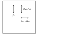
- FIG. FIG. 4 is a schematic diagram showing the relationship of the refractive indices in the linearly polarized light reflective film when the windshield glass of FIG. 3 is viewed from the front.
- FIG. 4 is a schematic diagram showing the arrangement of a windshield glass, a liquid crystal panel, and a luminance meter when evaluating the image color of the head-up display of the example.
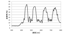
- Windshield glass No. produced in the example. 101 the natural light reflection spectrum at a light incident angle of 5°.
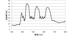
- Windshield glass No. produced in the example. 101 is the natural light reflection spectrum at a light incident angle of 60°.
- the term "to” is used to include the numerical values before and after it as lower and upper limits.
- the range of ⁇ 1 is a range including numerical value ⁇ 1 and numerical value ⁇ 1, and represented by mathematical symbols ⁇ 1 ⁇ 1 ⁇ 1.
- the "angle” represented by a specific numerical value such as 60°, and the terms “parallel” and “perpendicular”, unless otherwise specified generally in the technical field of the present invention Including the allowable margin of error. For example, it means being within a range of less than ⁇ 10° of the exact angle, and the error from the exact angle is preferably 7° or less, more preferably 5° or less.
- the term "sense" for circularly polarized light means whether it is right-handed circularly polarized light or left-handed circularly polarized light.
- the sense of circular polarization is right circular polarization if the tip of the electric field vector rotates clockwise as time increases, and left if it rotates counterclockwise when viewed as if the light were traveling toward you. Defined as being circularly polarized.
- the term "sense” is sometimes used for the twist direction of the cholesteric liquid crystal spiral.
- the helix direction (sense) of the cholesteric liquid crystal is right, it reflects right-handed circularly polarized light and transmits left-handed circularly polarized light.
- the sense is left, it reflects left-handed circularly polarized light and transmits right-handed circularly polarized light.
- the term "light” means visible light and natural light (non-polarized light) unless otherwise specified.
- Visible light is a wavelength of electromagnetic waves visible to the human eye, and means light in the wavelength range of 380 to 780 nm.
- Invisible light is light in the wavelength range below 380 nm or in the wavelength range above 780 nm.
- B light blue light
- G light green light
- R light red light
- infrared ray indicates a wavelength range of more than 780 nm and less than or equal to 2000 nm among non-visible light.
- the "visible light transmittance” is the A light source visible light transmittance defined in JIS (Japanese Industrial Standards) R 3212:2015 (automobile safety glass test method). That is, with a spectrophotometer using A light source, the transmittance of each wavelength in the wavelength range of 380 to 780 nm is measured, and obtained from the wavelength distribution and wavelength interval of the CIE (International Commission on Illumination) light adaptation standard relative luminosity It is the transmittance obtained by multiplying the transmittance at each wavelength by the weighting factor obtained and taking a weighted average. Further, when simply referring to "reflected light” or “transmitted light", it is used in the sense of including scattered light and diffracted light.
- JIS Japanese Industrial Standards
- R 3212:2015 automobile safety glass test method
- p-polarized light means polarized light that oscillates in a direction parallel to the plane of incidence of light.
- the plane of incidence means the plane that is perpendicular to the reflective surface (such as the windshield glass surface) and contains the incident and reflected rays.
- the plane of oscillation of the electric field vector is parallel to the plane of incidence.
- the front retardation is a value measured using AxoScan manufactured by Axometrics.
- the measurement wavelength is 550 nm.
- the front retardation can also be measured by KOBRA21ADH or WR (manufactured by Oji Keisoku Kiki Co., Ltd.) by allowing light of a wavelength within the visible light wavelength range to enter in the normal direction of the film.
- the wavelength selection filter can be manually replaced, or the measured value can be converted by a program or the like for measurement.
- the birefringence ( ⁇ n) of the liquid crystal compound is described in "Liquid Crystals/Fundamentals (edited by Koji Okano and Shunsuke Kobayashi)", p. It is a value measured according to the method described in 214. Specifically, ⁇ n at 60° C. can be obtained by injecting a liquid crystal compound into a wedge-shaped cell, irradiating the cell with light having a wavelength of 550 nm, and measuring the refraction angle of the transmitted light.
- the term "optically isotropic" in the “optically isotropic layer” means not exhibiting birefringence.
- the optical anisotropy in the “optically anisotropic layer” means exhibiting birefringence .
- the refractive index n o2 in the direction perpendicular to the in-plane slow axis direction (the in-plane fast axis direction) have a relationship of n e1 >n o2 .
- projection image means an image based on the projection of light from the projector used.
- the projected image is visually recognized by the observer as a virtual image that appears above the smooth portion of the windshield glass.
- screen image means an image displayed on a rendering device of a projector or an image rendered by a rendering device onto an intermediate image screen or the like.
- An image is a real image as opposed to a virtual image. Both the image and the projected image may be a monochromatic image, a multicolor image with two or more colors, or a full color image.
- liquid crystal compound is used to include those that no longer exhibit liquid crystallinity due to a curing reaction or the like.
- the HUD system of the present invention is typically used by being mounted on vehicles such as automobiles and trains, aircraft, and transport machines such as ships.
- HUD system head-up display system
- a HUD system of the present invention is a HUD system having a windshield glass having a selective reflection layer and a projector including a laser light source for forming a projected image on the windshield glass.
- the selective reflection layer includes the following three wavelengths ⁇ B , ⁇ G and ⁇ R as selective reflection central wavelengths at a light incident angle of 60 °, 400nm ⁇ ⁇ B ⁇ 500nm 500nm ⁇ G ⁇ 600nm 600nm ⁇ R ⁇ 700nm
- the laser light source emits laser light of three colors of blue light, green light and red light, A HUD system that satisfies all of the following provisions (a) to (c).
- LB indicates the luminance of blue laser light in the light emitted from the projector
- LG indicates the luminance of green laser light in the light emitted from the projector
- LR indicates the light emitted from the projector. shows the brightness of red laser light at .
- the selective reflection layer has a selective reflection center wavelength in a specific wavelength region, and the product of the natural light reflectance at these selective reflection center wavelengths and the brightness of the laser light in the light emitted from the projector is Adjusting the balance of the light intensity in the visible light region of the light reflected from the windshield glass by controlling to satisfy all of the above provisions (a) to (c), and making the image color neutral. can be done. That is, when a white image is projected, it is possible to project a white image that is not tinted. Although the laser light emitted from the projector passes through a medium (usually air) before entering the selective reflection layer in the windshield glass, the brightness of each color laser light is reduced by passing through this medium . , LG and LR are considered to modulate very little.
- FIG. 1 shows an example of the HUD system of the present invention.
- a HUD system 20 of the present invention shown in FIG. 1 includes a windshield glass 24 and a projector 22 .
- the projector 22 emits p-polarized projection light
- the reflective film 10 in the windshield glass 24 reflects the p-polarized light to display an image.
- the windshield glass 24 includes the windshield glass 24A including the linearly polarized light reflecting film 10A shown in FIG. It converts p-polarized projected light into circularly polarized light.
- the selective reflection layer 11 (cholesteric liquid crystal layer 12 ) selectively reflects this circularly polarized light and reenters the polarization conversion layer 14 .
- the polarization conversion layer 14 converts the circularly polarized light into p-polarized light.
- the linearly polarized light reflecting film 10A thereby reflects the incident p-polarized projection light as the p-polarized light.
- the polarization conversion layer 14 converts the incident p-polarized light into circularly polarized light in the rotating direction reflected by the selective reflection layer 11 according to the sense of the circularly polarized light selectively reflected by the selective reflection layer 11 (cholesteric liquid crystal layer 12). is set to convert to That is, when the selective reflection layer 11 selectively reflects right-handed circularly polarized light, the polarization conversion layer 14 is set to convert incident p-polarized light into right-handed circularly polarized light. Conversely, when the selective reflection layer 11 selectively reflects left-handed circularly polarized light, the polarization conversion layer 14 is set to convert incident p-polarized light into left-handed circularly polarized light.
- the projector 22 preferably illuminates the second glass plate 28 in the windshield glass 24 with p-polarized projection light.
- the projection light that the projector 22 irradiates onto the windshield glass 24 p-polarized light the reflection of the projection light from the first glass plate 30 and the second glass plate 28 of the windshield glass 24 is greatly reduced. Inconveniences such as the observation of double images can be suppressed.
- the projector 22 irradiates the windshield glass 24 with p-polarized projection light at Brewster's angle. This eliminates the reflection of the projection light on the first glass plate 30 and the second glass plate 28, making it possible to display a clearer image.
- the windshield glass 24 is windshield glass having a first glass plate 30, a reflective film 10 including a selective reflection layer, and a second glass plate 28 in this order.
- Windshield glass means window glass and windshield glass for vehicles such as cars and trains, airplanes, ships, motorcycles, and vehicles in general such as playground equipment.
- the windshield glass is preferably used as a windshield, a windshield, etc. in front of the traveling direction of the vehicle.
- the windshield glass 24A shown in FIG. 2 has a second glass plate 28, an intermediate film 36, a linearly polarized light reflecting film 10A, a heat seal layer 38, and a first glass plate 30 in this order.
- the linearly polarized light reflecting film 10A is arranged so that the polarization conversion layer 14 is on the second glass plate 28 side and the retardation layer 16 (transparent substrate 18) is on the first glass plate 30 side.
- the windshield glass 24B shown in FIG. 3 has the second glass plate 28, the intermediate film 36, the linearly polarized light reflecting film 10B, the intermediate film 36, and the first glass plate 30 in this order.
- the second glass plate 28 and the first glass plate 30 When the windshield glass is used in a vehicle, curved glass is often used as the second glass plate 28 and the first glass plate 30 . In that case, if the second glass plate 28 is on the inside of the vehicle and the first glass plate 30 is on the outside of the vehicle, the second glass plate 28 is arranged with the convex side facing the first glass plate 30, and the first The second glass plate 30 is arranged with the concave side facing the second glass plate 28 .
- the second glass plate 28 and the first glass plate 30 are curved glasses, the example shown in FIG.
- the conversion layer 14 and the selective reflection layer 11 are arranged in this order.
- the retardation layer 16 is arranged between the selective reflection layer 11 and the first glass plate 30 .
- the visible light transmittance of the windshield glass is preferably 70% or more, more preferably over 70%, still more preferably 75% or more, and particularly preferably 80% or more, from the viewpoint of legal regulations.
- the above-mentioned visible light transmittance is preferably satisfied at any position of the windshield glass, and it is particularly preferred that the above-mentioned visible light transmittance is satisfied at the position where the reflective film exists.
- the reflective film can increase the visible light transmittance, and in the case of using any glass generally used for windshield glass, the above-described visible light transmittance is satisfied. can do.
- the reflective film containing the selective reflection layer used in the present invention has a reflection peak derived from the selective reflection layer even when sandwiched between thick glasses.
- the windshield glass may be, for example, planar or three-dimensional with a curved surface such as a concave surface or a convex surface.
- the viewing side such as the upward direction in normal use, the viewer side, the driver side, and the inside of the vehicle.
- the reflective film may be provided on the projected image display portion (projected image reflection portion) of the windshield glass. Further, in the windshield glass, the reflective film may be provided between the glass panes of the windshield glass in the structure of laminated glass, or may be provided on the outer surface of the glass plate of the windshield glass. .
- the reflective film containing the selective reflection layer used in the present invention When the reflective film containing the selective reflection layer used in the present invention is provided on the outer surface of the glass plate of the windshield glass, the reflective film may be provided inside the vehicle (on the incident side of the projected image) or outside. However, it is preferably provided inside. In addition, the reflective film containing the selective reflection layer used in the present invention has lower scratch resistance than the glass plate. Therefore, when the windshield glass has a laminated glass structure, it is more preferable to provide the reflective film between two sheets of glass that constitute the laminated glass in order to protect the reflective film.
- the reflective film is a member for displaying a projected image by reflecting the projected image. Therefore, the reflective film may be provided at a position where a projection image projected from a projector or the like can be visually displayed. That is, the reflective film including the selective reflective layer used in the present invention functions as a combiner of the HUD system.
- the combiner can visually display the image projected from the projector, and when the combiner is observed from the incident surface side of the projected image, the incident surface of the projected light such as scenery is opposite to the incident surface. It means an optical member that can simultaneously observe information on the surface side. That is, the combiner has a function as an optical path combiner that superimposes external light and projected image light for display.
- the reflective film may be provided on the entire surface of the windshield glass, or may be provided on a part of the windshield glass in the surface direction, but it is preferably provided on a part of the windshield glass.
- the reflective film may be provided at any position on the windshield glass. is preferably provided as shown.
- the position of the reflective film on the windshield glass may be determined based on the relationship between the position of the driver's seat in the vehicle in which the HUD system is mounted and the position of the projector.
- the reflective film may be planar with no curved surface, or may have a curved surface.
- the reflective film may have a concave or convex shape as a whole, and may display the projected image by enlarging or reducing it.
- the reflective film 10 includes, as a selective reflection layer, three wavelengths of ⁇ B , ⁇ G and ⁇ R described later as selective reflection center wavelengths at a light incident angle of 60°, and each color in the laser light source There is no particular limitation as long as it includes a selective reflection layer that satisfies all of the below-described rules (a) to (c) with laser light.
- the windshield glass used in the HUD system of the present invention has the following selective reflection layer. That is, the selective reflection layer includes the following three wavelengths of ⁇ B , ⁇ G and ⁇ R as selective reflection center wavelengths at a light incident angle of 60°, 400 nm ⁇ B ⁇ 500 nm 500nm ⁇ ⁇ G ⁇ 600nm 600nm ⁇ R ⁇ 700nm All of the following provisions (a) to (c) are satisfied with the three color laser lights of blue, green and red emitted from the projector used in the HUD system of the present invention.
- LB indicates the brightness of the blue laser light in the light emitted from the projector
- LG indicates the brightness of the green laser light in the light emitted from the projector
- LR indicates the light emitted from the projector. shows the brightness of red laser light at .
- the units of the above natural light reflectances RB , RG and RR and the units of the luminances LB , LG and LR of the respective color laser beams in the light emitted from the projector are defined in (a) It suffices if they are unified so that the ratio of two of X B , X G and X R described in (c) can be taken correctly.
- the unit of the above natural light reflectances RB , RG and RR is %
- the unit of the brightness LB , LG and LR of each color laser light in the light emitted from the above projector is cd/m. 2 .
- the selective reflection central wavelength of the selective reflection layer and the half width of the reflection peak having this selective reflection central wavelength are obtained as follows.
- a spectrophotometer manufactured by JASCO Corporation, V-670
- a desired (for example, 60 °) light incident angle with respect to the normal direction of the selective reflection layer
- a maximum reflectance peak is observed in the selective reflection band.
- the value of the wavelength on the short wavelength side is ⁇ l (nm)
- the value of the wavelength on the long wavelength side is ⁇ l (nm).
- the selective reflection center wavelength obtained as described above is the centroid position of the reflection peak of the circularly polarized reflection spectrum measured at a desired light incident angle with respect to the normal direction of the selective reflection layer when the selective reflection layer is made of a cholesteric liquid crystal. approximately coincides with the wavelength at Further, in the present invention, the natural light reflectance at the selective reflection center wavelength of the selective reflection layer is also determined by the method described in Examples below. It should be noted that the reflection spectrum of the selective reflection layer is measured in the state of the windshield glass including the selective reflection layer, as described later in Examples.
- the brightness L B of the blue laser light in the light emitted from the projector, the brightness L G of the green laser light in the light emitted from the projector, and the brightness L R of the red laser light in the light emitted from the projector each means the luminance of blue laser light, the luminance of green laser light, and the luminance of red laser light in the light emitted from the projector.
- the luminance of each color laser light in the laser light source is the luminance of the laser light L B , LG and LR in the light emitted from the projector.
- the rendering device of the projector is provided with a laser luminance modulating means such as an external modulator
- the luminance of each color laser light after the luminance of the laser light in the laser light source is modulated by the laser luminance modulating means is the same as that of the above projector.
- the luminances LB , LG , and LR of the laser light in the light emitted from are also simply referred to as laser beam luminances LB , LG , and LR .
- the above blue, green, and red laser light luminances LB , LG , and LR are the natural light reflectances RB , RG , and RR of the selective reflection layer, and the above definition (a) It is adjusted as appropriate so as to satisfy all of (c).
- the luminances LB , LG , and LR of the above laser light are high luminance (for example, about 10000 cd/m2) in a bright environment such as daytime, and low luminance (for example, 3 cd/m2) in a dark environment such as nighttime. m 2 ) , it may be appropriately set according to the environment .
- the luminances L B , L G and L R of the above laser beams are measured by measuring the output light of each laser emitted from the projector with a luminance meter (for example, a luminance meter BM-5A (trade name) manufactured by Topcon Corporation). )).
- a luminance meter for example, a luminance meter BM-5A (trade name) manufactured by Topcon Corporation).
- ⁇ B is preferably in the wavelength range of 430 to 470 nm, more preferably in the wavelength range of 440 to 460 nm, in terms of the relationship with generally used blue, green and red laser light.
- ⁇ G is preferably in the wavelength range of 500 to 550 nm, more preferably in the wavelength range of 510 to 540 nm, and ⁇ R is preferably in the wavelength range of 600 to 650 nm, with a wavelength of 610 to 640 nm. A range is more preferred.
- the above provisions (a) to (c) are preferably the following provisions (a1) to (c1), respectively.
- Regulation (a1) 0.90 ⁇ X B /X G ⁇ 1.10
- Regulation (b1) 0.90 ⁇ X B /X R ⁇ 1.10
- Regulation (c1) 0.90 ⁇ X G /X R ⁇ 1.10
- X B , X G and XR have the same meanings as X B , X G and XR above.
- X B /X G , X B /X R , and X G /X R in the above provisions (a1) to (c1) are preferably 1.05 or less, and 1.03 It is more preferably 1.00 or less, more preferably 1.00 or less.
- the natural light reflectances RB , RG , and RR of the selective reflection layer are such that RB > RG ⁇ R from the viewpoint of making the reflected color closer to white at an incident angle of 60° and further improving transparency. It is preferable to satisfy the relationship of R.
- the natural light reflectances RB and RG of the selective reflection layer are RB / RG ⁇ 1.10 from the viewpoint of improving the transparency by making the reflected color closer to white at an incident angle of 5°. It is preferable to satisfy the relationship of
- the upper limit of RB / RG is not particularly limited, but 1.30 or less is practical.
- R G /R R is not particularly limited, but is practically 0.90 to 1.10, preferably 1.00 to 1.10.
- in-vehicle head-up display systems are required to have a transparent exterior color even when viewed from various angles in terms of transmittance and design that exceed legal requirements.
- it has been considered to lower the reflectance in order to maintain the legal transmittance of 70% or more and make the appearance color closer to transparent (white).
- the reflectance is lowered too much, the brightness of the displayed image (projected image) is lowered, resulting in poor visibility.
- the imager light is efficiently reflected, and the brightness of the image (clearness of the displayed image) can be increased while maintaining a high transmittance. Therefore, the selective reflection center wavelengths ⁇ B , ⁇ G , and ⁇ R contained in the selective reflection layer at an incident angle of 60° are all 100 nm or less, and the natural light reflectance R B , Both RG and RR are preferably 25% or more.
- the natural light transmittance is 70% or more (clear 80% or more with glass clamping).
- the natural light reflectance R B at ⁇ B , the natural light reflectance R G at ⁇ G , and the natural light reflectance R R at ⁇ R of the selective reflection layer are , both are preferably 25 to 60%, more preferably 30 to 50%.
- the natural light reflectance of the selective reflection layer used in the present invention at a light incident angle of 5° can be suppressed to less than 50%.
- the half-value width of the selective reflection center wavelength ⁇ B at a light incident angle of 60° is preferably 10 to 100 nm, more preferably 15 to 40 nm.
- the half width of the selective reflection central wavelength ⁇ G at the light incident angle of 60° is preferably 10 to 100 nm, and 15 to 55 nm. more preferred.
- the half-value width of the selective reflection center wavelength ⁇ R at the light incident angle of 60° is preferably 10 to 100 nm, more preferably 15 to 55 nm. more preferred.
- the selective reflection layer has a layer having a selective reflection center wavelength of 300 nm or more and less than 400 nm at an incident angle of 60 ° of light (for example, a cholesteric liquid crystal layer UV described later), this layer is preferably 330 to 395 nm , more preferably 350 to 390 nm, at an incident angle of 60°.
- the selective reflection layer preferably has a natural light reflectance R UV at ⁇ UV of 25 to 60%, more preferably 25 to 50%.
- the half-value width of the selective reflection center wavelength ⁇ UV at a light incident angle of 60° is preferably 10 to 100 nm, more preferably 15 to 40 nm.
- Examples of the reflective film including the above-described selective reflective layer include a linearly polarized reflective film including a cholesteric liquid crystal layer having a function of reflecting circularly polarized light, an optically anisotropic layer, and an optically isotropic layer.
- a linearly polarized light reflecting film including a selective reflection layer (hereinafter also referred to as a “dielectric multilayer film”) having a function of reflecting linearly polarized light is preferred.
- the linearly polarized light reflecting film will be described in order based on the linearly polarized light reflecting film 10A in the windshield glass 24A shown in FIG. 2 and the linearly polarized light reflecting film 10B in the windshield glass 24B shown in FIG. Further, the cholesteric liquid crystal layer and the dielectric multilayer film will be explained in the explanation of each linearly polarized light reflective film.
- FIG. 2 is a schematic diagram showing an example of the windshield glass 24 used in the present invention. , the polarization conversion layer 14, the selective reflection layer 11, the retardation layer 16, and the transparent substrate 18 in this order.
- the selective reflection layer 11 includes three cholesteric liquid crystal layers (12R, 12G, 12B).
- the three cholesteric liquid crystal layers have different selective reflection center wavelengths at a light incident angle of 60°. and a cholesteric liquid crystal layer 12R having a selective reflection center wavelength ⁇ R at a light incidence angle of 60°, which will be described later.
- it has a cholesteric liquid crystal layer 12R, a cholesteric liquid crystal layer 12G, and a cholesteric liquid crystal layer 12B in this order.
- each cholesteric liquid crystal layer is in direct contact with any other cholesteric liquid crystal layer.
- the central wavelength of selective reflection at a light incident angle of 60° is 300 nm or more and less than 400 nm.
- cholesteric liquid crystal layer UV is also preferable from the viewpoint of suppressing reflected color.
- the cholesteric liquid crystal layer is a layer in which a liquid crystal compound is fixed in the orientation state of the helical structure of the cholesteric liquid crystal phase, and reflects light of the selective reflection center wavelength according to the pitch of the helical structure, and reflects light of other wavelengths. permeates a wide range of light.
- the cholesteric liquid crystal layer exhibits selective reflectivity for either left or right circularly polarized light at a specific wavelength.
- the reflected wavelength and reflectance can be adjusted by the selective reflection center wavelength, thickness (helical pitch number), etc. of the cholesteric liquid crystal layer.
- each cholesteric liquid crystal layer is preferably in direct contact with any other cholesteric liquid crystal layer.
- a cholesteric liquid crystal layer 12R having a selective reflection central wavelength ⁇ R at a light incident angle of 60° and a cholesteric liquid crystal layer 12G having a selective reflection central wavelength ⁇ G at a light incident angle of 60°. are in contact with each other, and a cholesteric liquid crystal layer 12G having a selective reflection central wavelength ⁇ G at a light incident angle of 60° and a cholesteric liquid crystal layer 12B having a selective reflection central wavelength ⁇ B at a light incident angle of 60° in contact with each other.
- the film thickness between the layers becomes thicker, making it difficult to obtain the effect of interference of light reflected by each cholesteric liquid crystal layer.
- the wavelength band width can be narrowed by the effect of interference of light reflected by each cholesteric liquid crystal layer.
- the film thickness of each cholesteric liquid crystal layer is thinner than the wavelength of light (380 nm to 780 nm of visible light), the effect of interference becomes more pronounced.
- each cholesteric liquid crystal layer is not limited to a configuration in which they are in direct contact, and may be configured to be laminated via an adhesive layer or the like.
- each cholesteric liquid crystal layer has at least one selective reflection central wavelength among the three wavelengths ⁇ B , ⁇ G and ⁇ R described above as the selective reflection central wavelength at a light incident angle of 60°.
- at least one of the cholesteric liquid crystal layers may have two or more selective reflection central wavelengths.
- a cholesteric liquid crystal layer having two or more selective reflection center wavelengths is achieved by a helical structure in which the helical pitch varies in the thickness direction.
- the selective reflection layer 11 has three layers of cholesteric liquid crystal layers with different selective reflection center wavelengths, but the selective reflection layer 11 is not limited to this. It may have layers, or it may have two or four or more cholesteric liquid crystal layers.
- the total thickness of the selective reflection layer 11 is preferably 0.5 to 30 ⁇ m, more preferably 1 to 15 ⁇ m, from the viewpoint of exhibiting high transmittance while exhibiting sufficient natural light reflectance by the selective reflection layer 11 .
- the reflective film preferably reflects linearly polarized light.
- the projected image light is preferably p-polarized light, that is, linearly polarized light, in order to suppress reflection on the surface of the windshield glass.
- the selective reflection layer made of a cholesteric liquid crystal layer reflects circularly polarized light. Therefore, the linearly polarized light reflective film preferably has a layer for converting linearly polarized light incident on the reflective film into circularly polarized light.
- the layer that converts the polarization state of light includes a polarization conversion layer and a retardation layer.
- the polarization conversion layer exhibits optical rotation and birefringence with respect to visible light, and converts the polarization state of incident light.
- the polarization conversion layer is composed of a layer in which a birefringent material such as a liquid crystal compound is oriented with a twist amount of 360° or less.
- the phase difference layer changes the state of incident polarized light by adding a phase difference (optical path difference) to two orthogonal polarized light components.
- the retardation layer is a layer in which birefringent materials such as liquid crystal compounds are aligned in the same direction, and does not have optical rotation.
- the reflective film By configuring the reflective film to have a polarization conversion layer or a retardation layer on the light incident side of the selective reflective layer, the linearly polarized light incident on the reflective film is converted into circularly polarized light, and the selective reflective layer becomes circular.
- the polarized light can be reflected, and the reflected circularly polarized light can be converted into linearly polarized light by the polarization conversion layer or the retardation layer and emitted.
- the polarization conversion layer 14 is arranged on the side of the second glass plate 28, which is the inner side of the vehicle, and the retardation layer 16 is arranged on the side of the first glass plate 30, which is the outer side of the vehicle.
- the polarization conversion layer 14 has a function of converting projected p-polarized light (linearly polarized light) into circularly polarized light reflected by the cholesteric liquid crystal layer of the selective reflection layer 11 .
- the retardation layer 16 has an optical compensation function for light incident from outside the windshield glass. For example, s-polarized light incident from the outside of the windshield glass changes its polarization state when passing through the polarization conversion layer 14, and p-polarized light components are mixed. Since polarized sunglasses cut s-polarized light, this p-polarized component is transmitted through polarized sunglasses.
- the function of the polarized sunglasses to cut the glare of the reflected light, which is mainly composed of s-polarized light, is impaired, which poses a problem that hinders driving.
- the suitability for polarized sunglasses can be improved.
- the reflective film 10 has the polarization conversion layer 14 on the side of the second glass plate 28 on the inside of the vehicle, and the retardation layer 16 on the side of the first glass plate 30 on the outside of the vehicle.
- the reflective film 10 may be arranged such that the polarization conversion layer 14 is on the side of the first glass plate 30 on the vehicle exterior side, and the retardation layer 16 is on the side of the second glass plate 28 on the vehicle interior side.
- the retardation layer 16 has a function of converting projected p-polarized light (linearly polarized light) into circularly polarized light reflected by the cholesteric liquid crystal layer of the selective reflection layer 11 .
- the polarization conversion layer 14 has a function of optically compensating for light incident from the outside of the windshield glass, and by optically compensating with the polarization conversion layer 14, the suitability for polarized sunglasses can be improved.
- the reflective film may have a structure having polarization conversion layers on both sides of the selective reflection layer 11, or may have a structure having retardation layers on both sides.
- the polarization conversion layer or retardation layer disposed on the vehicle interior has a function of converting the projected p-polarized light (linearly polarized light) into circularly polarized light reflected by the cholesteric liquid crystal layer of the selective reflection layer 11. do it.
- the polarization conversion layer or the retardation layer arranged on the outside of the vehicle may be configured to have an optical compensation function for light incident from the outside of the windshield glass. The polarization conversion layer and the retardation layer will be detailed later.
- the cholesteric liquid crystal layer, the polarization conversion layer, the retardation layer, and the transparent substrate, which are constituent elements of the linearly polarized light reflective film including the cholesteric liquid crystal layer, will be described in detail below.
- the cholesteric liquid crystal layer includes the aforementioned three wavelengths ⁇ B , ⁇ G and ⁇ R as selective reflection center wavelengths at a light incident angle of 60°, and the above-mentioned definition ( There are no particular restrictions as long as the cholesteric liquid crystal layer satisfies all of a) to (c).
- the cholesteric liquid crystal layer means a layer in which the cholesteric liquid crystal phase is fixed.
- the cholesteric liquid crystal layer may be any layer as long as the alignment of the liquid crystal compound in the cholesteric liquid crystal phase is maintained.
- a cholesteric liquid crystal layer is typically formed by aligning a polymerizable liquid crystal compound in a cholesteric liquid crystal phase, and then polymerizing and curing by ultraviolet irradiation, heating, or the like to form a layer having no fluidity, and at the same time, Any layer may be used as long as it is changed to a state in which the orientation is not changed by an external field or external force.
- the cholesteric liquid crystal layer it is sufficient that the optical properties of the cholesteric liquid crystal phase are maintained in the layer, and the liquid crystal compound in the layer may no longer exhibit liquid crystallinity.
- the polymerizable liquid crystal compound may be polymerized by a curing reaction and no longer have liquid crystallinity.
- a cholesteric liquid crystal phase selectively reflects either right-handed circularly polarized light or left-handed circularly polarized light and transmits the other sense circularly polarized light.
- Many films formed from a composition containing a polymerizable liquid crystal compound are conventionally known as films containing a layer in which a cholesteric liquid crystal phase exhibiting selective reflection of circularly polarized light is fixed. You can refer to the technology.
- the pitch P of the helical structure (1 helical pitch) is, in other words, the length of the helical axis direction corresponding to one turn of the helical structure. is the length in the direction of the spiral axis that rotates 360°.
- the helical axis direction of a normal cholesteric liquid crystal layer coincides with the thickness direction of the cholesteric liquid crystal layer.
- the reflectance on the surface of the glass plate on the projection light incident side can be reduced.
- the light obliquely enters the cholesteric liquid crystal layer forming the selective reflection layer 11 of the reflection film 10 as well.
- light incident at an angle of 45° to 70° with respect to the normal to the reflective film 10 in air with a refractive index of 1 passes through the cholesteric liquid crystal layer with a refractive index of about 1.61 at an angle of about 26° to 36°.
- the reflected wavelength shifts to the short wavelength side.
- the light ray passes at an angle of ⁇ 2 with respect to the normal direction of the cholesteric liquid crystal layer (spiral axis direction of the cholesteric liquid crystal layer).
- a cholesteric liquid crystal layer having a selective reflection central wavelength ⁇ in the range of 650 to 780 nm can reflect projection light in the range of 520 to 695 nm when ⁇ 2 is 26° to 36°. Since such a wavelength range is a wavelength range with high luminosity, it has a high degree of contribution to the luminance of the projected image, and as a result, a projected image with high luminance can be realized.
- the helical pitch of the cholesteric liquid crystal phase depends on the type of chiral agent used together with the polymerizable liquid crystal compound and its concentration, so the desired pitch can be obtained by adjusting these.
- the method of measuring the sense and pitch of the helix the method described in "Introduction to Liquid Crystal Chemistry Experiments", edited by the Japanese Liquid Crystal Society, published by Sigma Publishing, 2007, page 46, and "Liquid Crystal Handbook", Liquid Crystal Handbook Editing Committee, Maruzen, page 196 is used. be able to.
- a cholesteric liquid crystal layer with either right or left helix sense is used for each cholesteric liquid crystal layer.
- the sense of circularly polarized light reflected by the cholesteric liquid crystal layer matches the sense of the helix.
- the helical sense of each cholesteric liquid crystal layer may be the same or different. However, it is preferred that the cholesteric liquid crystal layers all have the same sense of helix.
- the cholesteric liquid crystal layers exhibiting selective reflection in the same or overlapping wavelength ranges should not include cholesteric liquid crystal layers with different helical senses. is preferred. This is to prevent the transmittance in a specific wavelength range from dropping below 50%, for example.
- the ⁇ n can be adjusted by adjusting the type or mixing ratio of the polymerizable liquid crystal compound, or by controlling the temperature during orientation fixation.
- a plurality of cholesteric liquid crystal layers having the same pitch P and the same spiral sense may be laminated. By stacking cholesteric liquid crystal layers with the same pitch P and the same helical sense, the circular polarization selectivity can be increased at a particular wavelength.
- a separately prepared cholesteric liquid crystal layer may be laminated using an adhesive or the like, or the previous cholesteric liquid crystal layer formed by the method described later may be laminated.
- a liquid crystal composition containing a polymerizable liquid crystal compound or the like may be applied directly to the surface of the layer, and the alignment and fixing steps may be repeated, the latter being preferred.
- the thickness of the cholesteric liquid crystal layer is preferably 0.2-10 ⁇ m, more preferably 0.3-8 ⁇ m, and even more preferably 0.4-5 ⁇ m.
- a liquid crystal composition containing a polymerizable liquid crystal compound and a chiral agent (optically active compound) may be used as a material for forming the cholesteric liquid crystal layer. If necessary, the above liquid crystal composition mixed with a surfactant, a polymerization initiator, etc. and dissolved in a solvent, etc. is applied to the support, the alignment layer, the underlying cholesteric liquid crystal layer, etc., and cholesteric alignment is performed. After aging, the liquid crystal composition can be fixed by curing to form a cholesteric liquid crystal layer.
- the polymerizable liquid crystal compound may be a rod-like liquid crystal compound or a discotic liquid crystal compound, preferably a rod-like liquid crystal compound.
- An example of the rod-like polymerizable liquid crystal compound forming the cholesteric liquid crystal layer is a rod-like nematic liquid crystal compound.
- Rod-shaped nematic liquid crystal compounds include azomethines, azoxys, cyanobiphenyls, cyanophenyl esters, benzoic acid esters, cyclohexanecarboxylic acid phenyl esters, cyanophenylcyclohexanes, cyano-substituted phenylpyrimidines, and alkoxy-substituted phenylpyrimidines.
- phenyldioxanes, tolanes, and alkenylcyclohexylbenzonitriles are preferably used.
- low-molecular-weight liquid crystal compounds but also high-molecular liquid-crystal compounds can be used.
- a polymerizable liquid crystal compound is obtained by introducing a polymerizable group into a liquid crystal compound.
- polymerizable groups include unsaturated polymerizable groups, epoxy groups, and aziridinyl groups, with unsaturated polymerizable groups being preferred, and ethylenically unsaturated polymerizable groups being particularly preferred.
- Polymerizable groups can be introduced into molecules of liquid crystal compounds by various methods.
- the number of polymerizable groups possessed by the polymerizable liquid crystal compound is preferably 1 to 6, more preferably 1 to 3, in one molecule. Examples of polymerizable liquid crystal compounds are described in Makromol. Chem. , 190, 2255 (1989); Advanced Materials 5, 107 (1993); U.S. Pat. No.
- the amount of the polymerizable liquid crystal compound added in the liquid crystal composition is preferably 80 to 99.9% by mass, and preferably 85 to 99.5% by mass, based on the solid content mass (mass excluding the solvent) of the liquid crystal composition. % is more preferred, and 90 to 99% by mass is even more preferred.
- the cholesteric liquid crystal layer may have a low ⁇ n.
- a low ⁇ n cholesteric liquid crystal layer can be formed using a low ⁇ n polymerizable liquid crystal compound.
- the low ⁇ n polymerizable liquid crystal compound will be specifically described below.
- a narrow-band selective reflection layer can be obtained by forming a cholesteric liquid crystal phase using a low ⁇ n polymerizable liquid crystal compound and fixing it to a film.
- low ⁇ n polymerizable liquid crystal compounds include compounds described in WO2015/115390, WO2015/147243, WO2016/035873, JP-A-2015-163596 and JP-A-2016-053149.
- the description of WO2016/047648 can also be referred to for the liquid crystal composition that provides a selective reflection layer with a small half-value width.
- the liquid crystal compound is also preferably a polymerizable compound represented by the following formula (I) described in WO2016/047648.
- A represents an optionally substituted phenylene group or an optionally substituted trans-1,4-cyclohexylene group
- m represents an integer of 3 to 12
- the phenylene group in formula (I) is preferably a 1,4-phenylene group.
- the phenylene group and trans-1,4-cyclohexylene group may have 1 to 4 substituents.
- the two or more substituents may be the same or different.
- the alkyl group may be linear or branched.
- the number of carbon atoms in the alkyl group is preferably 1-30, more preferably 1-10, even more preferably 1-6.
- Examples of alkyl groups include methyl, ethyl, n-propyl, isopropyl, n-butyl, isobutyl, sec-butyl, tert-butyl, n-pentyl, isopentyl, and neopentyl. 1,1-dimethylpropyl, n-hexyl and isohexyl, and linear or branched heptyl, octyl, nonyl, decyl, undecyl and dodecyl can be done.
- alkyl groups also applies to alkoxy groups and alkoxycarbonyl groups containing alkyl groups.
- specific examples of the alkylene group when referred to as an alkylene group include a divalent group obtained by removing one arbitrary hydrogen atom in each of the examples of the above-mentioned alkyl groups, and the like.
- Halogen atoms include fluorine, chlorine, bromine and iodine atoms.
- the number of carbon atoms in the cycloalkyl group is preferably 3 to 20, the lower limit is more preferably 5 or more, and the upper limit is more preferably 10 or less, more preferably 8 or less, and particularly preferably 6 or less.
- Examples of cycloalkyl groups include cyclopropyl, cyclobutyl, cyclopentyl, cyclohexyl, cycloheptyl and cyclooctyl groups.
- X 3 represents a single bond, -O-, -S-, or -N(Sp 4 -Q 4 )-, or represents a nitrogen atom forming a ring structure together with Q 3 and Sp 3 show.
- the substitution position is not particularly limited. Among these, a tetrahydrofuranyl group is preferred, and a 2-tetrahydrofuranyl group is particularly preferred.
- m ⁇ 1 Ls may be the same or different.
- a linking group formed by combining two or more groups is preferred.
- Q 1 and Q 2 each independently represent a hydrogen atom or a polymerizable group represented by any one of the above formulas Q-1 to Q-5. However, at least one of Q 1 and Q 2 represents a polymerizable group, and both are preferably polymerizable groups.
- the polymerizable group an acryloyl group (formula Q-1) or a methacryloyl group (formula Q-2) is preferred.
- m represents an integer of 3-12.
- m is preferably an integer of 3 to 9, more preferably an integer of 3 to 7, and even more preferably an integer of 3 to 5.
- the polymerizable compound represented by formula (I) has at least one optionally substituted phenylene group as A and an optionally substituted trans-1,4-cyclohexylene group. It preferably contains at least one.
- the polymerizable compound represented by formula (I) preferably contains 1 to 4 optionally substituted trans-1,4-cyclohexylene groups as A, and preferably contains 1 to 3 groups. is more preferred.
- the polymerizable compound represented by formula (I) preferably contains one or more optionally substituted phenylene groups as A, more preferably 1 to 4 groups.
- polymerizable compound represented by formula (I) include, in addition to the compounds described in paragraphs 0051 to 0058 of WO2016/047648, JP-A-2013-112631, JP-A-2010-070543, Japanese Patent No. 4725516, WO2015/115390, WO2015/147243, WO2016/035873, JP-A-2015-163596, and compounds described in JP-A-2016-053149.
- the liquid crystal composition forming the low ⁇ n cholesteric liquid crystal layer contains polymerizable liquid crystal compounds other than the polymerizable compound represented by the formula (I) (hereinafter referred to as other polymerizable liquid crystal compounds). You may have Examples of other polymerizable liquid crystal compounds include polymerizable liquid crystal compounds other than the polymerizable compound represented by the above formula (I) among the compounds described as examples of the polymerizable liquid crystal compound.
- the proportion of the polymerizable compound represented by the above formula (I) in the total amount of polymerizable liquid crystal compounds is preferably 30 to 100% by mass, more preferably 50 to 100%. % by mass is more preferred, and 70 to 100% by mass is even more preferred.
- a chiral agent has a function of inducing a helical structure of a cholesteric liquid crystal phase.
- the chiral compound may be selected according to the purpose, since the helical sense or helical pitch induced by the compound differs.
- the chiral agent is not particularly limited, and commonly used compounds can be used. Examples of chiral agents include Liquid Crystal Device Handbook (Chapter 3, Section 4-3, Chiral Agents for TN and STN, p. Examples include compounds described in JP-A-2002-302487, JP-A-2002-080478, JP-A-2002-080851, JP-A-2010-181852, and JP-A-2014-034581.
- a chiral agent generally contains an asymmetric carbon atom, but an axially chiral compound or planar asymmetric compound that does not contain an asymmetric carbon atom can also be used as a chiral agent.
- axially or planarly chiral compounds include binaphthyl, helicene, paracyclophane, and derivatives thereof.
- the chiral agent may have a polymerizable group. When both the chiral agent and the liquid crystal compound have a polymerizable group, a repeating unit derived from the polymerizable liquid crystal compound and a repeating unit derived from the chiral agent are formed by the polymerization reaction of the polymerizable chiral agent and the polymerizable liquid crystal compound.
- the polymerizable group possessed by the polymerizable chiral agent is preferably the same type of group as the polymerizable group possessed by the polymerizable liquid crystal compound. Therefore, the polymerizable group of the chiral agent is also preferably an unsaturated polymerizable group, an epoxy group or an aziridinyl group, more preferably an unsaturated polymerizable group, and an ethylenically unsaturated polymerizable group. More preferred. Also, the chiral agent may be a liquid crystal compound.
- isosorbide derivatives As the chiral agent, isosorbide derivatives, isomannide derivatives, binaphthyl derivatives and the like can be preferably used.
- isosorbide derivative a commercially available product such as LC756 (trade name) manufactured by BASF may be used.
- the content of the chiral agent in the liquid crystal composition is preferably 0.01 to 200 mol %, more preferably 1 to 30 mol % of the amount of the polymerizable liquid crystal compound.
- the cholesteric liquid crystal layer of the selective reflection layer of the linearly polarized light reflection film may have two or more selective reflection central wavelengths.
- a cholesteric liquid crystal layer having two or more selective reflection central wavelengths is achieved by changing the pitch of the helical structure in the thickness direction.
- the cholesteric liquid crystal layer, in which the pitch of the helical structure changes in the thickness direction is formed by using a chiral agent whose helical twisting power (HTP) changes when irradiated with light. It can be produced by changing the irradiation amount of light in the direction.
- HTP helical twisting power
- Chiral agents whose HTP is changed by light irradiation include those that undergo re-isomerization, dimerization, isomerization and dimerization, etc. by light irradiation.
- the photoisomerizable group is preferably an isomerization site of a compound exhibiting photochromic properties, an azo group, an azoxy group, or a cinnamoyl group.
- Specific compounds include JP-A-2002-080478, JP-A-2002-080851, JP-A-2002-179668, JP-A-2002-179669, JP-A-2002-179670, JP-A-2002- 179681, JP-A-2002-179682, JP-A-2002-338575, JP-A-2002-338668, JP-A-2003-313189, and compounds described in JP-A-2003-313292, etc. can be used.
- the liquid crystal composition preferably contains a polymerization initiator.
- the polymerization initiator to be used is preferably a photopolymerization initiator capable of initiating the polymerization reaction by ultraviolet irradiation.
- photoinitiators include ⁇ -carbonyl compounds (described in US Pat. Nos. 2,367,661 and 2,367,670), acyloin ether compounds (described in US Pat. No. 2,448,828), ⁇ -carbon A hydrogen-substituted aromatic acyloin compound (described in US Pat. No.
- an acylphosphine oxide compound or an oxime compound As the polymerization initiator, it is also preferable to use an acylphosphine oxide compound or an oxime compound.
- acylphosphine oxide compound for example, a commercially available product, IRGACURE810 (trade name, compound name: bis(2,4,6-trimethylbenzoyl)-phenylphosphine oxide) manufactured by BASF Japan Ltd. can be used.
- oxime compounds include IRGACURE OXE01 (trade name, manufactured by BASF), IRGACURE OXE02 (trade name, manufactured by BASF), TR-PBG-304 (trade name, manufactured by Changzhou Tenryu Electric New Materials Co., Ltd.), and Adeka Arcles NCI.
- the content of the photopolymerization initiator in the liquid crystal composition is preferably 0.1 to 20% by mass, more preferably 0.5 to 5% by mass, based on the content of the polymerizable liquid crystal compound.
- the liquid crystal composition may optionally contain a cross-linking agent in order to improve film strength and durability after curing.
- a cross-linking agent one that is cured by ultraviolet rays, heat, humidity, or the like can be preferably used.
- the cross-linking agent is not particularly limited and can be appropriately selected depending on the purpose.
- cross-linking agents include polyfunctional acrylate compounds such as trimethylolpropane tri (meth) acrylate and pentaerythritol tri (meth) acrylate; epoxy compounds such as glycidyl (meth) acrylate and ethylene glycol diglycidyl ether; aziridine compounds such as bishydroxymethylbutanol-tris[3-(1-aziridinyl)propionate], 4,4-bis(ethyleneiminocarbonylamino)diphenylmethane; isocyanate compounds such as hexamethylene diisocyanate and biuret type isocyanate; polyoxazoline compounds having chains; alkoxysilane compounds such as vinyltrimethoxysilane and N-(2-aminoethyl)3-aminopropyltrimethoxysilane; In addition, a commonly used catalyst can be used depending on the reactivity of the cross-linking agent, and productivity can be improved in addition to improvement in film strength
- the content of the cross-linking agent in the liquid crystal composition is preferably 3 to 20% by mass, more preferably 5 to 15% by mass, based on the solid mass (mass excluding the solvent) of the liquid crystal composition.
- the content of the cross-linking agent is preferably 3 to 20% by mass, more preferably 5 to 15% by mass, based on the solid mass (mass excluding the solvent) of the liquid crystal composition.
- An alignment control agent may be added to the liquid crystal composition to contribute to stably or rapidly forming a planar alignment cholesteric liquid crystal layer.
- alignment control agents include fluorine (meth)acrylate polymers described in paragraphs [0018] to [0043] of JP-A-2007-272185, paragraphs [0031] to [0031] of JP-A-2012-203237. 0034] and the like, compounds represented by formulas (I) to (IV), and compounds described in JP-A-2013-113913.
- the alignment control agent one type may be used alone, or two or more types may be used in combination.
- the amount of the alignment control agent added in the liquid crystal composition is preferably 0.01 to 10% by mass, more preferably 0.01 to 5% by mass, and more preferably 0.02 to 1% based on the total mass of the polymerizable liquid crystal compound. % by weight is particularly preferred.
- the liquid crystal composition may contain at least one selected from various additives such as a surfactant for adjusting the surface tension of the coating film to make the thickness uniform, and a polymerizable monomer.
- the liquid crystal composition may further contain polymerization inhibitors, antioxidants, ultraviolet absorbers, light stabilizers, colorants, metal oxide fine particles, etc. to the extent that the optical performance is not reduced. can be added at
- the cholesteric liquid crystal layer comprises a liquid crystal composition obtained by dissolving a polymerizable liquid crystal compound, a polymerization initiator, a chiral agent, a surfactant, etc. added as necessary in a solvent, a transparent substrate, a retardation layer, and an alignment layer. Alternatively, it is coated on the previously prepared cholesteric liquid crystal layer or the like, dried to obtain a coating film, and the coating film is irradiated with actinic rays to polymerize the cholesteric liquid crystal composition, and the cholesteric regularity is fixed.
- cholesteric liquid crystal layer can be formed.
- a laminated film composed of a plurality of cholesteric liquid crystal layers can be formed by repeating the above-described manufacturing process of the cholesteric liquid crystal layer.
- the solvent used for preparing the liquid crystal composition is not particularly limited and can be appropriately selected depending on the intended purpose, but an organic solvent is preferably used.
- the organic solvent is not particularly limited and can be appropriately selected depending on the purpose. Examples include ketones, alkyl halides, amides, sulfoxides, heterocyclic compounds, hydrocarbons, esters and ethers. and the like. These may be used individually by 1 type, and may use 2 or more types together. Among these, ketones are particularly preferable in consideration of the load on the environment.
- the method of applying the liquid crystal composition to the transparent substrate, the alignment layer, the underlying cholesteric liquid crystal layer, and the like is not particularly limited, and can be appropriately selected according to the purpose.
- coating methods include wire bar coating, curtain coating, extrusion coating, direct gravure coating, reverse gravure coating, die coating, spin coating, dip coating, spray coating, and slide coating. law, etc. It can also be carried out by transferring a liquid crystal composition separately coated on a support.
- the liquid crystal molecules are aligned by heating the applied liquid crystal composition.
- the heating temperature is preferably 200° C. or lower, more preferably 130° C. or lower.
- the liquid crystal composition can be cured.
- Polymerization may be either thermal polymerization or photopolymerization using light irradiation, but photopolymerization is preferred. It is preferable to use ultraviolet rays for light irradiation.
- the irradiation energy is preferably 20 mJ/cm 2 to 50 J/cm 2 , more preferably 100 to 1,500 mJ/cm 2 .
- light irradiation may be performed under heating conditions or under a nitrogen atmosphere.
- the irradiation ultraviolet wavelength is preferably 350 to 430 nm.
- the polymerization reaction rate is preferably as high as possible. Specifically, it is preferably 70% or more, more preferably 80% or more.
- the polymerization reaction rate can be determined by measuring the consumption rate of the polymerizable functional groups by infrared absorption spectrum measurement.
- the polarization conversion layer 14 is a layer in which the helical orientation structure of the liquid crystal compound is fixed, and the pitch number x of the helical orientation structure and the film thickness y (unit ⁇ m) of the polarization conversion layer satisfy the following relational expressions (a) to (c ) are preferably satisfied.
- Expression (c) Note that one pitch of the helical structure of the liquid crystal compound is one turn of the helical structure of the liquid crystal compound. That is, the pitch number is 1 when the director of the helically aligned liquid crystal compound (long axis direction in the case of rod-like liquid crystal) is rotated by 360°.
- the polarization conversion layer When the polarization conversion layer has a helical structure of a liquid crystal compound, it exhibits optical rotation and birefringence with respect to visible light whose wavelength is shorter than the reflection peak wavelength in the infrared region. Therefore, polarization in the visible range can be controlled.
- the polarization conversion layer By setting the pitch number x of the helically oriented structure of the polarization conversion layer and the film thickness y of the polarization conversion layer within the above ranges, the polarization conversion layer has a function of optically compensating for visible light, or a straight line incident on the reflective film. A function of converting polarized light (p-polarized light) into circularly polarized light can be imparted.
- the polarization conversion layer exhibits optical rotation and birefringence with respect to visible light due to the liquid crystal compound having a helical structure that satisfies the relational expressions (a) to (c).
- the pitch P of the helical structure of the polarization conversion layer is set to a length corresponding to the pitch P of the cholesteric liquid crystal layer whose selective reflection center wavelength is in the infrared region with a long wavelength, for visible light with a short wavelength, It exhibits high optical rotation and birefringence.
- the relational expression (a) is "0.1 ⁇ x ⁇ 1.0". If the pitch number x of the helical structure is less than 0.1, problems such as insufficient optical rotation and birefringence will occur. On the other hand, if the pitch number x of the helical structure exceeds 1.0, the optical rotatory power and birefringence are excessive, resulting in problems such as failure to obtain desired elliptically polarized light.
- the relational expression (b) is "0.5 ⁇ y ⁇ 3.0". If the thickness y of the polarization conversion layer is less than 0.5 ⁇ m, the film thickness is too thin, resulting in problems such as insufficient optical rotation and birefringence. If the thickness y of the polarization conversion layer exceeds 3.0 ⁇ m, the optical rotation and birefringence are excessive, resulting in problems such as failure to obtain desired circularly polarized light and poor orientation, which is undesirable for manufacturing.
- the relational expression (c) is "3000 ⁇ (1560 ⁇ y)/x ⁇ 50000". If “(1560 ⁇ y)/x” is less than 3000, the optical rotatory power is excessive and the desired polarized light cannot be obtained. If “(1560 ⁇ y)/x” exceeds 50000, the optical rotatory power is insufficient, resulting in problems such as failure to obtain desired polarized light.
- the pitch number x of the helical structure of the polarization conversion layer is more preferably 0.1 to 0.8, and the film thickness y is more preferably 0.6 ⁇ m to 2.6 ⁇ m. Further, "(1560 ⁇ y)/x" is more preferably 5000 to 13000.
- the polarization conversion layer preferably has a long spiral structure pitch P and a small pitch number x.
- the polarization conversion layer preferably has a spiral pitch P equal to the pitch P of the cholesteric liquid crystal layer whose selective reflection central wavelength is in the long wavelength infrared region, and the number of pitches x is small.
- the polarization conversion layer preferably has a spiral pitch P equal to the pitch P of the cholesteric liquid crystal layer having a selective reflection center wavelength of 3000 to 10000 nm, and a small number of pitches x.
- the central wavelength of selective reflection corresponding to the pitch P is much longer than that of visible light, so that the above-described optical rotation and birefringence with respect to visible light are more favorably exhibited.
- Such a polarization conversion layer can be basically formed in the same manner as a commonly used cholesteric liquid crystal layer.
- the liquid crystal compound to be used should be such that the pitch number x of the helical structure and the film thickness y [ ⁇ m] in the polarization conversion layer satisfy all of the relational expressions (a) to (c). , the chiral agent to be used, the amount of the chiral agent added, the film thickness, etc. must be adjusted.
- the layer in which the helical alignment structure (helical structure) of the liquid crystal compound is fixed is a so-called cholesteric liquid crystal layer, and means a layer in which the cholesteric liquid crystal phase is fixed.
- the cholesteric liquid crystal layer may be any layer as long as the orientation of the liquid crystal compound in the cholesteric liquid crystal phase is maintained.
- a cholesteric liquid crystal layer is typically formed by aligning a polymerizable liquid crystal compound in a cholesteric liquid crystal phase, and then polymerizing and curing by ultraviolet irradiation, heating, or the like to form a layer having no fluidity, and at the same time, Any layer may be used as long as it is changed to a state in which the orientation is not changed by an external field or external force.
- the cholesteric liquid crystal layer it is sufficient that the optical properties of the cholesteric liquid crystal phase are maintained in the layer, and the liquid crystal compound in the layer may no longer exhibit liquid crystallinity.
- the polymerizable liquid crystal compound may be polymerized by a curing reaction and no longer have liquid crystallinity.
- the helical pitch of the cholesteric liquid crystal phase depends on the type of chiral agent used together with the polymerizable liquid crystal compound and the concentration thereof added, a desired pitch can be obtained by adjusting these.
- the cholesteric liquid crystal layer used as the polarization conversion layer has its spiral pitch adjusted so that the central wavelength of selective reflection is in the long wavelength infrared region.
- the method of forming the cholesteric liquid crystal layer as the polarization conversion layer is basically the same as the method of forming the cholesteric liquid crystal layer described above.
- the phase difference layer changes the state of incident polarized light by adding a phase difference (optical path difference) to two orthogonal polarized light components.
- the front retardation of the retardation layer may be a retardation that can be optically compensated.
- the retardation layer preferably has a front retardation of 50 nm to 160 nm at a wavelength of 550 nm.
- the angle of the slow axis is 10 ° to 50 °. Alternatively, it is preferably -50° to -10°.
- the front retardation of the retardation layer is preferably configured to give ⁇ / 4, and the front retardation is 3 ⁇ / 4 may be provided. Also, the angle of the slow axis may be arranged so as to change the incident linearly polarized light into circularly polarized light.
- the retardation layer preferably has a front retardation of 100 to 450 nm at a wavelength of 550 nm, more preferably 120 to 200 nm or 300 to 400 nm.
- the direction of the slow axis of the retardation layer is the direction of incidence of projection light for displaying a projected image when the reflective film 10 is used in a head-up display system, and the cholesteric liquid crystal layer constituting the selective reflection layer. is preferably determined according to the sense of the helix of
- the retardation layer is not particularly limited and can be appropriately selected according to the purpose.
- the retardation layer include a stretched polycarbonate film, a stretched norbornene-based polymer film, an oriented transparent film containing inorganic particles having birefringence such as strontium carbonate, and an inorganic dielectric material on a support. , a film obtained by uniaxially aligning a polymerizable liquid crystal compound and fixing its orientation, and a film obtained by uniaxially orienting a liquid crystal compound and fixing its orientation.
- a film in which a polymerizable liquid crystal compound is uniaxially oriented and oriented and fixed is preferably exemplified as the retardation layer.
- a retardation layer is formed, for example, by applying a liquid crystal composition containing a polymerizable liquid crystal compound to the surface of a transparent substrate, a temporary support, or an alignment layer, where the polymerizable liquid crystal compound in the liquid crystal composition is added to the liquid crystal. After being formed into a nematic orientation in the state, it can be fixed by curing and formed. Formation of the retardation layer in this case can be carried out in the same manner as the formation of the cholesteric liquid crystal layer described above, except that the chiral agent is not added to the liquid crystal composition.
- the heating temperature is preferably 50 to 120.degree. C., more preferably 60 to 100.degree.
- the retardation layer is formed by coating a composition containing a polymer liquid crystal compound on the surface of a transparent base material, a temporary support, an alignment layer, or the like, forming a nematic alignment in a liquid crystal state, and then fixing this alignment by cooling. It may be a layer obtained by reducing the
- the thickness of the retardation layer is not limited, it is preferably 0.2 to 300 ⁇ m, more preferably 0.5 to 150 ⁇ m, even more preferably 1.0 to 80 ⁇ m.
- the thickness of the retardation layer formed from the liquid crystal composition is not particularly limited, but is preferably 0.2 to 10 ⁇ m, more preferably 0.5 to 5.0 ⁇ m, even more preferably 0.7 to 2.0 ⁇ m. .
- the slow axis is set by tilting, for example, at an angle ⁇ with respect to an axis in an arbitrary direction of the retardation layer.
- the direction of the slow axis can be set, for example, by rubbing the alignment film that is the lower layer of the retardation layer.
- the linearly polarized light reflective film may have layers other than the selective reflection layer, polarization conversion layer, and retardation layer described above.
- the linearly polarized light reflective film may have a transparent substrate, an adhesive layer, and the like.
- the linearly polarized light reflective film 10A has a transparent substrate 18 arranged on the side of the retardation layer 16 opposite to the selective reflection layer 11 .
- the transparent substrate 18 supports the retardation layer 16 , the selective reflection layer 11 (cholesteric liquid crystal layer), and the polarization conversion layer 14 .
- the transparent substrate 18 may be used as a support for forming the retardation layer 16, the selective reflection layer 11 (cholesteric liquid crystal layer), and the polarization conversion layer 14.
- the linearly polarized light reflective film may be in the form of a thin film or sheet.
- the linearly polarized light reflective film may be in the form of a roll or the like as a thin film before being used for windshield glass.
- Both the transparent substrate (support) and the adhesive layer are preferably transparent in the visible light region. Moreover, it is preferable that both the transparent substrate and the adhesive layer have low birefringence. Low birefringence means that the front phase difference is 10 nm or less in the wavelength region where the selective reflection layer contained in the windshield glass used in the present invention exhibits reflection. This front retardation is preferably 5 nm or less. Furthermore, it is preferable that the support, the adhesive layer, etc. have a small difference in refractive index from the average refractive index (in-plane average refractive index) of the selective reflection layer.
- the transparent substrate can also be used as a substrate when forming a selective reflection layer.
- the transparent substrate used for forming the selective reflection layer may be a temporary support that is peeled off after the formation of the selective reflection layer. Therefore, the finished reflective film and windshield glass may not contain a transparent substrate.
- the transparent substrate is preferably transparent in the visible light region.
- transparent substrates include polyesters such as polyethylene terephthalate (PET), polycarbonates, acrylic resins, epoxy resins, polyurethanes, polyamides, polyolefins, cellulose derivatives, and plastic films such as silicones.
- PET polyethylene terephthalate
- acrylic resins acrylic resins
- epoxy resins epoxy resins
- polyurethanes polyamides
- polyolefins polyolefins
- cellulose derivatives cellulose derivatives
- plastic films such as silicones.
- plastic films such as silicones.
- glass may be used in addition to the plastic film described above.
- the thickness of the transparent substrate may be about 5.0 to 1000 ⁇ m, preferably 10 to 250 ⁇ m, more preferably 15 to 90 ⁇ m.
- the transparent base material 18 when the transparent base material 18 is arranged on the side of the first glass plate 30, that is, on the outside of the vehicle, the transparent base material 18 may contain an ultraviolet absorber. preferable. By including an ultraviolet absorber in the transparent base material 18, deterioration of the reflective film (selective reflection layer) due to ultraviolet rays can be suppressed.
- FIG. 3 is a schematic diagram showing an example of the windshield glass used in the present invention.
- optically anisotropic layers 13Ra, 13Ga, 13Ba
- optically isotropic layers 13Rb, 13Gb, 13Ba
- the linearly polarized light reflecting film 10B includes a first laminated portion 13R in which an optically anisotropic layer 13Ra and an optically isotropic layer 13Rb are alternately laminated, an optically anisotropic layer 13Ga and an optically isotropic layer 13Gb.
- the dielectric multilayer film includes the aforementioned three wavelengths ⁇ B , ⁇ G and ⁇ R as selective reflection center wavelengths at a light incident angle of 60°, and the above-mentioned There are no particular restrictions as long as the dielectric multilayer film satisfies all of the requirements (a) to (c).
- the thicknesses of the optically anisotropic layers and the optically isotropic layers of the first laminated section 13R, the second laminated section 13G and the third laminated section 13B are different from each other. Also, the number of layers, the refractive index, and the like may be different.
- the refractive index n e1 in the slow axis direction of the optically anisotropic layer exceeds the refractive index n o2 of the optically isotropic layer (that is, n e1 >n o2 ), and the optical The refractive index no1 in the direction orthogonal to the slow axis of the anisotropic layer is substantially the same as the refractive index no2 of the optically isotropic layer.
- a plurality of optically anisotropic layers are laminated such that the slow axes thereof are parallel to each other. Therefore, as shown in FIG. 4, in one direction (vertical direction in FIG.
- a layer having a high refractive index (n e1 ) and a layer having a low refractive index (n o2 ) are laminated.
- layers having the same refractive index are laminated.
- a film in which layers with a low refractive index (low refractive index layers) and layers with a high refractive index (high refractive index layers) are alternately laminated has a structural structure between many low refractive index layers and high refractive index layers. Interference is known to reflect certain wavelengths of light. Therefore, the linearly polarized light reflecting film 10B shown in FIGS. 3 and 4 reflects linearly polarized light in the vertical direction in FIG. 4 and transmits linearly polarized light in the horizontal direction.
- the dielectric multilayer film used in the HUD system of the present invention includes the aforementioned three wavelengths ⁇ B , ⁇ G and ⁇ R as selective reflection central wavelengths at an incident angle of 60° of light, and a laser light source All of the above-mentioned regulations (a) to (c) are satisfied between each color laser light in .
- the selective reflection central wavelength and the reflectance can be adjusted by the refractive index difference, thickness, number of layers, etc. between the low refractive index layer and the high refractive index layer.
- the first lamination portion 13R mainly realizes reflection having the selective reflection center wavelength ⁇ R at an incident angle of 60° of the light described above
- the second lamination portion 13G realizes the reflection of the light described above.
- the reflection having the selective reflection center wavelength ⁇ G at an incident angle of 60° is realized
- the reflection having the selective reflection center wavelength ⁇ B at the incident angle of 60° is realized by the third laminated portion 13B.
- the reflection peak having the selective reflection central wavelength determined by the above-described method has a maximum value with a difference of 2% or more from the adjacent minimum value, and a half value width of 10 to 10. Let the peak be at 200 nm.
- the half width of the reflection peak having each selective reflection center wavelength depends on the difference between the refractive index in the slow axis direction of the optically anisotropic layer and the refractive index of the optically isotropic layer, and the refractive index difference is The larger the value, the larger the half width. Also, if the reflection peaks with low reflectance are at close wavelengths, they interfere with each other, causing a phenomenon in which the reflection peaks become too strong or too weak. Appropriately adjusting the half width of the reflection peak having each selective reflection center wavelength to improve the brightness of the displayed image while increasing the transmittance, and reducing the influence of interference with adjacent reflection peaks.
- the difference between the refractive index in the slow axis direction of the optically anisotropic layer and the refractive index of the optically isotropic layer is preferably 0.03 to 0.20, more preferably 0.05 to 0.14. is more preferably 0.05 to 0.10.
- the dielectric multilayer film includes a light reflecting layer having the above-described ⁇ B , a light reflecting layer having the above-described ⁇ G , and a light having the above-described ⁇ R as the selective reflection center wavelength at a light incident angle of 60 °. It is preferably composed of reflective layers and these light reflective layers are in contact with each other. For example, in the example shown in FIG. 3, the first laminated portion 13R having the selective reflection central wavelength ⁇ R at the light incident angle of 60° and the second laminated portion 13R having the selective reflection central wavelength ⁇ G at the light incident angle of 60°.
- the first lamination portion 13R, the second lamination portion 13G, and the third lamination portion 13B are light reflection layers that form dielectric multilayer films (selective reflection layers) used in the HUD system of the present invention.
- a selective reflection layer (hereinafter referred to as a light reflection layer UV) formed by laminating an anisotropic layer and an optically isotropic layer from the viewpoint of suppressing reflected color.
- the film thickness between the layers becomes thick, and the effect of interference of the light reflected by each light reflecting layer becomes difficult to obtain.
- the half width of the reflection peak having each selective reflection center wavelength can be narrowed by the effect of interference of light reflected by each light reflecting layer. can be done.
- the above-mentioned linearly polarized light reflective film may be in the form of a thin film, a sheet, or the like.
- the linearly polarized reflective film may be in the form of a thin film, such as a roll, before being used for windshield glass.
- Materials and methods for manufacturing the dielectric multilayer film can be those described in, for example, Japanese Patent Publication No. 9-506837.
- a wide variety of materials can be used to form dielectric multilayer films when processed under conditions selected to obtain refractive index relationships.
- the first material has a different refractive index than the second material in the chosen direction.
- This refractive index difference can be achieved in a variety of ways, including stretching, extrusion, or coating during film formation or after film formation.
- it is preferred that the two materials have similar rheological properties (eg, melt viscosities) so that they can be coextruded.
- Materials particularly preferably used for the dielectric multilayer film include PEN (polyethylene naphthalate) and PET (polyethylene terephthalate) as materials for the optically anisotropic layer, and (isotropic polymethyl methacrylate), PEN, PET and PMMA (polymethyl methacrylate resin).
- the linearly polarized light reflective film (dielectric multilayer film) used in the HUD system of the present invention has three wavelengths of ⁇ B , ⁇ G and ⁇ R as selective reflection center wavelengths at an incident angle of 60° of light. It is preferable to have three laminated portions in which the optically anisotropic layer and the optically isotropic layer have different thicknesses.
- the laminated parts are bonded together to produce a linearly polarized light reflecting film (dielectric multilayer film).
- the thickness before processing may be adjusted so that three laminated portions having different thicknesses are formed, and the three laminated portions may be integrally formed by stretching, extrusion molding, or the like.
- the thickness of the dielectric multilayer film is preferably 2.0-50 ⁇ m, more preferably 8.0-30 ⁇ m.
- a linearly polarized light reflective film containing a dielectric multilayer film has a selective reflection layer (dielectric multilayer film) formed by laminating an optically anisotropic layer and an optically isotropic layer.
- the linearly polarized light reflective film may have a structure including a retardation layer, a polarization conversion layer, a support, an adhesive layer, etc., in addition to the dielectric multilayer film.
- the retardation layer, the polarization conversion layer, the support (transparent base material), and the adhesive layer used in the linearly polarized light reflective film are the retardation layer used in the linearly polarized light reflective film containing the cholesteric liquid crystal layer, The descriptions of the polarization conversion layer, the transparent substrate (support), and the adhesive layer can be applied.
- the constituent elements of the windshield glass the glass plate (laminated glass), the intermediate layer, and the heat seal layer (adhesive layer) will be described in order as constituent elements other than the above-mentioned reflective film.
- the windshield glass may have a structure of laminated glass.
- the windshield glass used in the HUD system of the present invention is laminated glass and has the above-described reflective film between the first glass plate and the second glass plate.
- the windshield glass may have a configuration in which a reflective film is arranged between the first glass plate and the second glass plate.
- the windshield glass has an intermediate film (intermediate film sheet) provided between at least one of the first glass plate and the reflective film and between the reflective film and the second glass plate. is preferred.
- the second glass plate is arranged on the opposite side (vehicle outer side) to the image viewing side in the HUD system, and the first glass plate is arranged on the viewing side (vehicle inner side).
- the first and second in the first glass plate and the second glass plate have no technical meaning, and distinguish between the two glass plates.
- the second glass plate may be on the inside of the vehicle and the first glass plate may be on the outside of the vehicle.
- glass plates such as the first glass plate and the second glass plate
- glass plates commonly used for windshield glass can be used.
- a glass plate having a visible light transmittance of 80% or less such as 73% or 76%, such as green glass with high heat shielding properties, may be used. Even when such a glass plate with a low visible light transmittance is used, by using the above-mentioned reflective film, a windshield glass having a visible light transmittance of 70% or more even at the position of the reflective film can be obtained. can be made.
- the thickness of the glass plate is not particularly limited, but may be about 0.5 to 5.0 mm, preferably 1.0 to 3.0 mm, more preferably 2.0 to 2.3 mm.
- the materials or thicknesses of the first glass plate and the second glass plate may be the same or different.
- a windshield glass having a structure of laminated glass can be produced by a conventional method for producing laminated glass. In general, after sandwiching an interlayer film for laminated glass between two glass plates, heat treatment and pressure treatment (treatment using a rubber roller, etc.) are repeated several times, and finally an autoclave or the like is used. It can be produced by a method of performing heat treatment under pressurized conditions.
- a windshield glass having a structure of laminated glass having a reflective film and an intermediate film may be produced, for example, by forming a reflective film on the surface of a glass plate and then using the method for producing laminated glass described above, or alternatively, The intermediate film for laminated glass containing the reflective film of No. 1 may be used and produced by the method for producing laminated glass described above.
- the glass plate on which the reflective film is provided may be the first glass plate or the second glass plate.
- the reflective film may be bonded to the glass plate with an adhesive (heat seal layer), for example.
- the intermediate film 36 prevents the glass from penetrating into the vehicle interior and scattering when an accident occurs.
- the linearly polarizing reflective film 10A and the second glass plate 28 are adhered, and in the example shown in FIG. 1, the reflective film 10 is adhered to the second glass plate 28,
- the linearly polarized light reflecting film 10B is adhered to the second glass plate 28 and the first glass plate 30. As shown in FIG.
- any intermediate film commonly used as an intermediate film (intermediate layer) in laminated glass can be used as the intermediate film (intermediate film sheet).
- a resin film containing a resin selected from polyvinyl butyral (PVB), ethylene-vinyl acetate copolymer and chlorine-containing resin can be used.
- the resin described above is preferably the main component of the intermediate film.
- being a main component means the component which occupies 50 mass % or more of an intermediate film.
- polyvinyl butyral at least one of polyvinyl butyral and ethylene-vinyl acetate copolymer is preferred, and polyvinyl butyral is more preferred.
- the resin is preferably a synthetic resin.
- Polyvinyl butyral can be obtained by acetalizing polyvinyl alcohol with butyraldehyde.
- the preferred lower limit of the degree of acetalization of polyvinyl butyral is 40% or more, the preferred upper limit is 85% or less, the more preferred lower limit is 60% or more, and the more preferred upper limit is 75% or less.
- Polyvinyl alcohol is generally obtained by saponifying polyvinyl acetate, and polyvinyl alcohol having a degree of saponification of 80 to 99.8 mol % is generally used. Moreover, the preferable lower limit of the degree of polymerization of polyvinyl alcohol is 200 or more, and the preferable upper limit thereof is 3000 or less. When the degree of polymerization of polyvinyl alcohol is 200 or more, the penetration resistance of the resulting laminated glass is less likely to decrease. Good workability. A more preferable lower limit is 500 or more, and a more preferable upper limit is 2000 or less.
- the thickness of the intermediate film 36 is not limited, and the thickness may be set in accordance with the forming material, etc., in the same manner as the intermediate film of the commonly used windshield glass.
- the windshield glass 24 has a heat seal layer 38 provided between the reflective film 10 and the first glass plate 30, and the reflective film 10 and the second glass plate 28 are bonded with an intermediate film 36. wearing, but not limited to. That is, a heat seal layer may be provided between the reflective film 10 and the second glass plate 28 and an intermediate film may be provided between the reflective film 10 and the first glass plate 30 .
- the windshield glass 24 is configured without the intermediate film 36, and the adhesion between the reflective film 10 and the second glass plate 28 and the adhesion between the reflective film 10 and the first glass plate 30 are A configuration using the heat seal layer 38 may be used.
- An intermediate film for laminated glass containing a reflective film can be formed by bonding a reflective film to the surface of the intermediate film described above.
- the reflective film can be sandwiched between the two intermediate films described above.
- the two intermediate films may be the same or different, and are preferably the same.
- a commonly used bonding method can be used for bonding the reflective film and the intermediate film, and it is preferable to use a lamination treatment.
- the lamination process is preferably carried out under a certain degree of heat and pressure conditions so that the laminate (reflective film) and the intermediate film are not separated after processing.
- the film surface temperature of the adhesive side of the intermediate film is preferably 50 to 130.degree.
- pressurization conditions are not limited, it is preferably less than 2.0 kg/cm 2 (less than 196 kPa), more preferably 0.5 to 1.8 kg/cm 2 (49 to 176 kPa), and 0.5 to 1.5 kg. /cm 2 (49 to 147 kPa) is more preferable.
- the support when the reflective film has a support (transparent substrate), the support may be peeled off simultaneously with lamination, immediately after lamination, or immediately before lamination. That is, the reflective film attached to the intermediate film obtained after lamination may be free of a support.
- An example of a method for producing an intermediate film containing a reflective film is (1) A first step of bonding a reflective film to the surface of the first intermediate film to obtain a first laminate, and (2) A second step of bonding a second intermediate film to a surface of the reflective film in the first laminate opposite to the surface to which the first intermediate film is bonded.
- the reflective film and the first intermediate film are bonded without facing the support and the first intermediate film.
- the support is then peeled off from the reflective film.
- a second intermediate film is attached to the surface from which the support has been peeled off.
- laminated glass in which the reflective film does not have a support can be easily produced.
- the temperature of the support when peeling the support from the reflective film is preferably 40°C or higher, more preferably 40 to 60°C.
- the heat seal layer (adhesive layer) 38 is a layer made of, for example, a coating type adhesive.
- the linearly polarized reflective film 10A is adhered to the first glass plate 30 with the heat seal layer 38.
- the linearly polarized light reflecting film 10A may be adhered to the first glass plate 30 by an intermediate film. If the linearly polarized light reflecting film 10A is smaller than the intermediate film 36 that adheres the second glass plate 28 and the linearly polarized light reflecting film 10A together, the intermediate film 36 separates the linearly polarized light reflecting film 10A from the first film. may be attached to the glass plate 30 of
- the heat seal layer 38 there are no restrictions on the heat seal layer 38, and various commonly used materials can be used as long as they can ensure the transparency required for the windshield glass 24 and can adhere the reflective film 10 and the glass with the necessary adhesion force. are available.
- the same material as the intermediate film 36 such as PVB may be used for the heat seal layer 38 .
- the heat seal layer 38 may use an adhesive such as an acrylate adhesive, as described below.
- the heat seal layer 38 may be formed from an adhesive.
- Adhesives include hot-melt type, heat-curing type, photo-curing type, reaction-curing type, and pressure-sensitive adhesive type that does not require curing from the viewpoint of curing methods.
- adhesives of any type are made of acrylate, urethane, urethane acrylate, epoxy, epoxy acrylate, polyolefin, modified olefin, polypropylene, ethylene vinyl alcohol, vinyl chloride, Compounds selected from chloroprene rubber-based, cyanoacrylate-based, polyamide-based, polyimide-based, polystyrene-based, and polyvinyl butyral-based compounds can be used.
- the light-curing type is preferable as the curing method, and from the viewpoint of optical transparency and heat resistance, the material is a compound selected from acrylate, urethane acrylate, epoxy acrylate, etc. is preferably used.
- the heat seal layer 38 may be formed using a highly transparent adhesive transfer tape (OCA tape).
- OCA tape a commercially available product for image display devices, particularly a commercially available product for the surface of the image display portion of the image display device may be used.
- Examples of commercially available products include an adhesive sheet manufactured by Panac Corporation (trade name: PD-S1, etc.), an adhesive sheet of the MHM (trade name) series manufactured by Nichiei Kako Co., Ltd., and the like.
- the thickness of the heat seal layer 38 is also not limited. Therefore, the thickness that provides sufficient adhesive strength may be appropriately set according to the material forming the heat seal layer 38 . Here, if the heat seal layer 38 is too thick, it may not be possible to adhere the reflective film 10 to the second glass plate 28 or the first glass plate 30 while maintaining sufficient flatness. Considering this point, the thickness of the heat seal layer 38 is preferably 0.1 to 800 ⁇ m, more preferably 0.5 to 400 ⁇ m.
- a "projector” is a “device for projecting light or an image", including a “device for projecting a rendered image”, that emits projection light carrying an image to be displayed.
- the projector includes a laser light source that emits laser light of three colors of blue light, green light and red light, and the above-mentioned provisions (a) to (c) with the above-mentioned selective reflection layer
- the projector should be positioned so that the projected light carrying the image to be displayed (preferably p-polarized projected light) is incident at an oblique angle of incidence on the reflective film in the windshield glass. good.
- the projector preferably includes a rendering device and reflects and displays an image (real image) rendered on a small intermediate image screen by a combiner as a virtual image.
- a commonly used projector used in a HUD system can be used as long as it can emit p-polarized projection light.
- the projector has a variable imaging distance of the virtual image, ie, a variable imaging position of the virtual image.
- Methods for changing the imaging distance of the virtual image in the projector include, for example, a method of moving the image generation surface (screen) (see Japanese Patent Application Laid-Open No. 2017-21302), and a method of switching and using a plurality of optical paths with different optical path lengths. (see WO2015/190157), a method of changing the optical path length by inserting and/or moving a mirror, a method of changing the focal length by using a combined lens as an imaging lens, a method of moving the projector 22, and forming a virtual image. Examples include a method of switching and using a plurality of projectors with different distances, a method of using a variable focus lens (see WO2010/116912), and the like.
- the projector may be one in which the imaging distance of the virtual image can be changed continuously, or one in which the imaging distance of the virtual image can be switched between two or three or more points.
- the driver's line-of-sight distance is greatly different, such as driving at normal speed on a general road and driving at high speed on a highway.
- a rendering device may itself be a device that displays an image, or it may be a device that emits light capable of rendering an image.
- the light from the light source may be adjusted by a drawing method such as an optical modulator, laser luminance modulation means, or light deflection means for drawing.
- a drawing device means a device that includes a light source and, depending on the drawing method, an optical modulator, a laser luminance modulation means, or an optical deflection means for drawing.
- the light source used in the HUD system of the present invention is a laser light source that emits three colors of laser light, blue light, green light and red light, and the above-mentioned provisions (a) to (c) with the above-mentioned selective reflection layer ) is not particularly limited as long as it is possible to satisfy all of the above conditions, and commonly-used laser light sources used in projectors, drawing devices, displays, etc. can be used, and semiconductor lasers are preferably used.
- the peak emission wavelength of blue laser light is 450 ⁇ 10 nm
- the peak emission wavelength of green laser light is 518 ⁇ 7 nm
- the peak wavelength of green laser light is 518 ⁇ 7 nm.
- the peak wavelength of emitted light is generally 638 ⁇ 5 nm.
- the absolute value of the difference between the peak wavelength of the emission wavelength of the blue laser light and the selective reflection center wavelength ⁇ B in the selective reflection layer is usually 10 nm or less, preferably 5 nm or less.
- the absolute value of the difference between the peak wavelength of the emission wavelength of green light laser light and the selective reflection central wavelength ⁇ G in the selective reflection layer is usually 7 nm or less, preferably 4 nm or less.
- the absolute value of the difference between the peak wavelength of the emission wavelength of the laser light and the selective reflection center wavelength ⁇ R of the selective reflection layer is usually 5 nm or less, preferably 3 nm or less.
- the drawing method can be selected according to the laser light source that emits the three colors of blue, green, and red laser light, and examples thereof include a scanning method using a laser.
- the scanning method is a method in which a light beam is scanned on a screen and an image is formed using an afterimage of the eye.
- brightness-modulated laser beams of, for example, red, green, and blue colors are bundled into a single beam by a combining optical system, a condenser lens, or the like, and the beam is converted into light. It is sufficient that the image is scanned by the deflection means and drawn on an intermediate image screen, which will be described later.
- the luminance modulation of each color laser light such as red light, green light, and blue light may be performed directly as intensity change of the light source, or may be performed by an external modulator.
- Examples of the light deflection means include a galvanomirror, a combination of a galvanomirror and a polygon mirror, and MEMS (Micro Electro Mechanical Systems), among which MEMS is preferred.
- Scanning methods include a random scan method, a raster scan method, and the like, and it is preferable to use the raster scan method.
- the laser light can be driven, for example, with a resonant frequency in the horizontal direction and a sawtooth wave in the vertical direction. Since the scanning method does not require a projection lens, it is easy to reduce the size of the device.
- a light source module having blue, green, and red laser light sources irradiates RGB light onto a biaxial MEMS mirror, and drives the MEMS mirror at high speed to form an image on an intermediate image screen with RGB reflected light.
- a raster scan method for drawing is common.
- Light emitted from the drawing device may be linearly polarized light or natural light (non-polarized light).
- a drawing device using a laser light source essentially emits linearly polarized light.
- the polarization directions (transmission axis directions) of the light of the plurality of wavelengths are preferably the same. It is known that some commercially available drawing devices do not have a uniform polarization direction in the wavelength regions of red, green, and blue emitted light (see Japanese Patent Application Laid-Open No. 2000-221449).
- the projection light emitted from the projector is preferably p-polarized light.
- the rendering device may use an intermediate image screen.
- An "intermediate image screen” is a screen on which an image is rendered. That is, when the light emitted from the drawing device is not yet visible as an image, the drawing device forms a visible image on the intermediate image screen with this light.
- the image rendered on the intermediate image screen may be projected onto the combiner by light passing through the intermediate image screen, or may be reflected onto the intermediate image screen and projected onto the combiner.
- intermediate image screens include scattering films, microlens arrays, and screens for rear projection.
- a plastic material is used as the intermediate image screen
- the intermediate image screen if the intermediate image screen has birefringence, the plane of polarization and light intensity of the polarized light incident on the intermediate image screen are disturbed, resulting in color unevenness, etc. in the combiner (reflection film).
- the problem of color unevenness can be reduced by using a retardation film having a predetermined retardation.
- the intermediate image screen preferably has the function of spreading and transmitting the incident light. This is because the projected image can be enlarged and displayed.
- Such intermediate image screens include, for example, screens composed of microlens arrays.
- Microarray lenses used in HUD systems are described, for example, in JP-A-2012-226303, JP-A-2010-145745, and JP-A-2007-523369.
- the projector may include a reflecting mirror or the like that adjusts the optical path of the projection light formed by the drawing device.
- HUD systems using windshield glass as a reflective film are disclosed in JP-A-2-141720, JP-A-10-96874, JP-A-2003-98470, US Pat. 2006-512622 and the like can be referred to.
- Incident light is preferably incident at an oblique incident angle of 45° to 70° with respect to the normal to the reflective film.
- the Brewster angle at the interface between glass with a refractive index of about 1.51 and air with a refractive index of 1 is about 56°.
- the amount of reflected light from the surface of the windshield glass on the viewing side is less than that of the selective reflection layer of (1), and image display with little influence of double images is possible. It is also preferred that said angle is between 50° and 65°.
- the projected image can be observed on the incident side of the projected light at an angle of 45° to 70°, preferably 50° to 65°, on the side opposite to the incident light with respect to the normal line of the selective reflection layer. Any configuration can be used.
- the incident light may enter from any direction, such as the top, bottom, left, or right of the windshield glass, and may be determined in accordance with the viewing direction. For example, a configuration in which light is incident from below at the time of use at an oblique incident angle as described above is preferable. Also, the reflective film of the windshield glass is preferably arranged to reflect incident p-polarized light.
- the projection light for displaying a projected image in the HUD system of the present invention is p-polarized light that oscillates in a direction parallel to the plane of incidence.
- the light emitted from the projector is not linearly polarized light, it may be p-polarized by providing a linear polarizing film (polarizer) on the side of the light emitted from the projector.
- P-polarized light may also be obtained by a conventional method using such as.
- a member that converts non-linearly polarized projection light into p-polarized light is also considered to constitute the projector in the HUD system of the present invention.
- the polarization direction in the wavelength regions of red, green, and blue emitted light is not uniform
- the polarization direction is adjusted in a wavelength-selective manner, and all color wavelength regions are converted to p-polarized light. Incidence is preferred.
- the HUD system may be a projection system in which the virtual image forming position is variable.
- the virtual image forming position is variable.
- the virtual image formation position is a position where the driver of the vehicle can visually recognize the virtual image, for example, a position 1000 mm or more away from the windshield glass as viewed from the driver.
- the vertical direction Y of the windshield glass 24 is a direction corresponding to the vertical direction of a vehicle or the like in which the windshield glass 24 is arranged, and is defined as the ground side being the lower side and the opposite side being the upper side. is.
- the windshield glass 24 may be arranged at an angle for reasons of structure or design. direction.
- the surface is the exterior side of the vehicle.
- the present invention is basically configured as described above. Although the HUD system of the present invention and its constituent elements, such as the windshield glass, have been described in detail above, the present invention is not limited to the above-described embodiments, and various modifications or It is of course possible to make changes.
- Coating liquid for forming a cholesteric liquid crystal layer The following components are mixed so as to have the composition ratio shown below, and each cholesteric liquid crystal layer (UV1, B1, Each narrow-band cholesteric liquid crystal layer-forming coating solution for forming G1 and R1) was prepared.
- Rod-shaped liquid crystal compound 102
- Rod-shaped liquid crystal compounds 201 and 202 are identical to Rod-shaped liquid crystal compounds 201 and 202:
- each cholesteric liquid crystal layer-forming coating solution prepared above each cholesteric liquid crystal layer of a single layer having a thickness of about 3 ⁇ m (cured by polymerization reaction) was formed on a temporary support in the same manner as in the preparation of the cholesteric liquid crystal layer described later. layer) was prepared. It was confirmed that all of the cholesteric liquid crystal layers prepared were right-handed circularly polarized light reflective layers, and that the selective reflection central wavelength (central wavelength) and the half width of the reflection peak were the wavelengths shown in Table 1 below. The selective reflection central wavelength and the half width of the reflection peak shown in Table 1 are the values measured by measuring the reflection spectrum of the [Evaluation ⁇ ] selective reflection layer described later.
- a retardation layer-forming coating liquid was prepared by mixing the following components so as to have the composition ratio shown below.
- ⁇ Mixture 1 100 parts by mass
- ⁇ Fluorine-based horizontal alignment agent 1 (alignment control agent 1)
- 0.05 mass parts
- ⁇ Fluorine-based horizontal alignment agent 2 alignment control agent 2
- ⁇ Polymerization initiator IRGACURE OXE01 (product name, manufactured by BASF)
- Solvent methyl ethyl ketone
- the selective reflection center wavelength ⁇ of the polarization conversion layer obtained from the coating solution for forming the polarization conversion layer prepared above was 10000 nm at a light incident angle of 5°.
- the selective reflection central wavelength ⁇ at the incident angle of 5° of light was obtained by using the coating liquid for forming the polarization conversion layer prepared above to prepare a single-layer cholesteric liquid crystal layer having a thickness of about 3 ⁇ m on the temporary support.
- FTIR Fastier Transform Infrared Spectroscopy, manufactured by PerkinElmer, trade name: Spectrum Two).
- the film thickness d of the helical structure is represented by "the pitch P of the helical structure.times.the number of pitches".
- the pitch P of the helical structure means the thickness of the layer when the helically aligned liquid crystal compound rotates 360°.
- Example 1 Preparation of windshield glass ⁇ 1-1> Preparation of selective reflection layer composed of cholesteric liquid crystal layer (1) Preparation of saponified cellulose acylate film Described in Example 20 of WO 2014/112575 100 parts by mass of cellulose acetate (ester oligomer cellulose acylate dope with a thickness of 40 ⁇ m except that a core layer cellulose acylate dope containing 3 parts by mass of an ultraviolet absorber UV-531 (trade name) manufactured by Teisei Kako Co., Ltd. was used. An acylate film was produced. The produced cellulose acylate film was passed through a dielectric heating roll at a temperature of 60°C to raise the film surface temperature to 40°C.
- an alkaline solution having the composition shown below was applied to one side of the film using a bar coater so that the coating amount was 14 mL/m 2 , and heated to 110 ° C. with a steam type far-infrared heater (manufactured by Noritake Co., Ltd.). ) for 10 seconds. Then, using the same bar coater, pure water was applied so as to be 3 mL/m 2 . Subsequently, washing with water using a fountain coater and draining with an air knife were repeated three times, and then the film was dried by staying in a drying zone at 70°C for 5 seconds to prepare a saponified cellulose acylate film (transparent support). The in-plane retardation of the saponified cellulose acylate film was measured with AxoScan (manufactured by Axometrics, trade name) and found to be 1 nm.
- AxoScan manufactured by Axometrics, trade name
- the retardation layer-forming coating solution prepared above was applied to the rubbed surface of the alignment film on the support using a wire bar, and then dried. Next, it is placed on a hot plate at 50° C. and irradiated with ultraviolet rays for 6 seconds by an electrodeless lamp “D bulb” (60 mW/cm 2 ) manufactured by Fusion UV Systems in an environment with an oxygen concentration of 1000 ppm or less to convert the liquid crystal phase. Fixed. As a result, a retardation layer having a thickness adjusted so as to provide a desired frontal retardation, that is, a desired retardation, was obtained. When the retardation of the produced retardation layer was measured by AxoScan (manufactured by Axometrics, trade name), it was 126 nm.
- the coating liquid for forming the cholesteric liquid crystal layer (UV1) prepared above is applied, and the thickness of the film after drying is shown in Table 3 below.
- a coating layer was obtained by coating at room temperature using a wire bar so as to obtain a film thickness. After drying the coating layer at room temperature for 30 seconds, it was heated in an atmosphere of 85° C. for 2 minutes. After that, in an environment with an oxygen concentration of 1000 ppm or less, ultraviolet light is irradiated at 60° C. for 6 to 12 seconds with a D bulb (60 mW/cm 2 lamp) manufactured by Fusion Co., Ltd. at an output of 60% to fix the cholesteric liquid crystal phase.
- a D bulb 60 mW/cm 2 lamp
- a cholesteric liquid crystal layer UV1 having a thickness shown in Table 3 below.
- a cholesteric liquid crystal layer B1 On the surface of the obtained cholesteric liquid crystal layer UV1, a cholesteric liquid crystal layer B1, a cholesteric liquid crystal layer G1, and a cholesteric liquid crystal layer R1 are laminated in this order so as to have the film thicknesses shown in Table 3 below, A laminate was obtained in which four cholesteric liquid crystal layers were laminated on the retardation layer.
- each of the cholesteric liquid crystal layers B1, G1 and R1 is used for forming the corresponding cholesteric liquid crystal layers (B1, G1 and R1) instead of the coating solution for forming the cholesteric liquid crystal layer (UV1) in the preparation of the cholesteric liquid crystal layer UV1.
- Each layer was prepared in the same manner, except that the coating solution for the above was used.
- No. The selective reflection layer of No. 106 was prepared in the same manner, except that the cholesteric liquid crystal layer UV1 was not provided and the cholesteric liquid crystal layer B1 was laminated on the surface of the retardation layer.
- the coating solution for forming the polarization conversion layer prepared above was applied to the outermost surface of the cholesteric liquid crystal layer in the obtained laminate so as to have a thickness of 1.7 ⁇ m.
- a polarization conversion layer (twisted layer) was formed.
- the polarization conversion layer was formed in the same manner as in the preparation of the cholesteric liquid crystal layer described above, except that the coating liquid for forming the polarization conversion layer was used instead of the coating liquid for forming the cholesteric liquid crystal layer.
- the resulting polarization conversion layer was a twisted layer with a selective reflection center wavelength of ⁇ 10000 nm and a pitch number of 0.265.
- a laminate (this laminate is also referred to as a "reflection film”) is produced by laminating the retardation layer, the selective reflection layer and the polarization conversion layer in this order on the support (transparent substrate). bottom.
- PEN 2,6-polyethylene naphthalate
- coPEN copolyester of 70 mol % naphthalate and 30 mol % terephthalate
- PEN 2,6-polyethylene naphthalate
- coPEN copolyester of 70 mol % naphthalate and 30 mol % terephthalate
- the resulting monolayer films of PEN and coPEN were extruded, stretched at a draw ratio of 5:1 at about 150°C, and heat treated at about 230°C for 30 seconds.
- the PEN film has a refractive index of about 1.86 with respect to the slow axis (orientation axis) and a refractive index of 1.64 with respect to the transverse axis. 0.64.
- the PEN film has a refractive index about 1.71 for the slow axis and a refractive index about 1.64 for the transverse axis, and the coPEN film is isotropic, with a refractive index of about It was confirmed to be 1.64. That is, the difference ⁇ n between the refractive index in the slow axis direction of the PEN film, which is the optically anisotropic layer, and the refractive index of the coPEN film, which is the optically isotropic layer, is 0.07.
- a laminate obtained by coextrusion of PEN and coPEN was stretched and heat-treated to prepare a linearly polarized light reflective film (also referred to as a “reflective film”).
- the thickness of this linearly polarized light reflective film is about 28 ⁇ m, and the linearly polarized light reflective layer UV2 having 44 layers of PEN and coPEN alternately having the film thickness shown in the UV2 column of Table 2 below, B2 of Table 2 below.
- a linearly polarized light reflecting layer B2 having 44 alternating layers of PEN and coPEN with the film thickness indicated in the column, a linearly polarized light reflecting layer G2 having 39 layers of alternating PEN and coPEN with the film thickness indicated in the column of G2, and It has a linearly polarized light reflecting layer R2 having 38 layers of PEN and coPEN alternately having the film thicknesses shown in the row R2, in this order.
- UV2 layer, B2 layer After preparing each laminate corresponding to the G2 layer and the R2 layer before stretching, the laminate obtained by laminating all of
- ⁇ 2-1> Preparation of windshield glass having a selective reflection layer composed of a cholesteric liquid crystal layer
- the support (transparent base material), the retardation layer, the selective reflection layer, and the polarization conversion layer prepared above are laminated in this order.
- a laminate formed by A laminated body was prepared by laminating the glass plates in this order.
- the heat-seal layer in the above laminate is obtained by applying a heat-seal layer-forming coating liquid to the support (transparent substrate) side of the selective reflection layer made of the cholesteric liquid crystal layer using a wire bar and then drying it for 50 minutes.
- a heat seal layer having a thickness of 1 ⁇ m was formed by heat-treating at °C for 1 minute. After holding the obtained laminate at 90° C.
- ⁇ 2-2> Preparation of windshield glass having a selective reflection layer made of a linearly polarized light reflecting film Using the linearly polarized light reflecting film prepared above, a second glass plate, an intermediate film, and a selective reflection layer (dielectric multilayer film) are formed. , an intermediate film, and a first glass plate were laminated in this order to prepare a laminate. After holding the obtained laminate at 90° C. and 10 kPa (0.1 atmosphere) for 1 hour, it was heated in an autoclave (manufactured by Kurihara Seisakusho) at 115° C. and 1.3 MPa (13 atmospheres) for 20 minutes to remove air bubbles. Remove the windshield glass No. 105 was obtained. The linearly polarized light reflecting layer UV2 in the linearly polarized light reflecting film was placed on the first glass plate side, and the linearly polarized light reflecting layer R2 was placed on the second glass plate side.
- an autoclave manufactured by Kurihara Seisakusho
- the windshield glass was used by cutting each layer into the same shape as the first glass plate and the second glass plate.
- the glass plate, the intermediate film, and the coating solution for forming the heat seal layer used for the production of the windshield glass are as follows.
- As the first glass plate and the second glass plate glass plates having a length of 120 mm, a width of 100 mm, and a thickness of 2 mm (FL2, visible light transmittance of 90%, manufactured by Central Glass Co., Ltd.) were used.
- a 0.38 mm-thick PVB (polyvinyl butyral) film manufactured by Sekisui Chemical Co., Ltd. was used as an intermediate film.
- a heat seal layer-forming coating liquid prepared by mixing the following components so as to have the composition ratio shown below was used.
- each coating liquid for forming each cholesteric liquid crystal layer (UV1, B1, G1 and R1)
- each coating liquid for the reflective layer described in Table 2 of JP-A-2018-81296 ( UV, B, G and R) were used in the same manner.
- the optical properties of each cholesteric liquid crystal layer (UV3, B3, G3 and R3) in c11 are the same as the optical properties of each reflective layer (UV, B, G and R) described in Table 3 of JP-A-2018-81296. are the same.
- No. 1 was measured by setting the incident angle of light to 60°.
- the half width of the reflection peak having each selective reflection center wavelength in the selective reflection layer c11 was 30 nm for the cholesteric liquid crystal layer UV3, 35 nm for the cholesteric liquid crystal layer B3, 45 nm for the cholesteric liquid crystal layer G3, and 47 nm for the cholesteric liquid crystal layer R3. .
- Example 2 Design of head-up display Windshield glass No. 1 produced above. 101 to 106 and c11, and a projector including a laser light source for forming a projected image.
- 201 to 206 and c21 were designed so that the second glass plate side of each windshield glass was the side on which the light from the laser light source was incident.
- Head-up display system No. 201 to 206 are head-up display systems of the present invention.
- c21 is a comparative head-up display system.
- the graph shown in FIG. It is a reflection spectrum measured by light incident at an angle of 60° with respect to the normal direction of the surface of 101 .
- the selective reflection center wavelength (60°), reflectance (60°) and half width (60°) were measured by light incident at an angle of 60° with respect to the normal direction of the windshield glass surface.
- the average value of the reflectance when P-polarized light is incident and the reflectance when S-polarized light is incident is synonymous with the reflectance when unpolarized light (natural light) is incident. That is, the average value of the P-polarized reflection spectrum and the S-polarized reflection spectrum is synonymous with the reflection spectrum when natural light is incident.
- each selective reflection center wavelength ⁇ and its half width ⁇ in the wavelength band of 400 nm or more and less than 500 nm, the wavelength band of 500 nm or more and less than 600 nm, and the wavelength band of 600 nm to 700 nm were calculated by the method described above, based on the two wavelengths at which the maximum value of the natural light reflectance and the reflectance between the maximum maximum value and the minimum minimum value of the natural light reflectance were obtained. Further, the reflectance at each selective reflection center wavelength ⁇ was the reflectance value at the selective reflection center wavelength ⁇ in the calculated average value of the reflection spectra of P-polarized light and S-polarized light.
- A
- a projector composed of an RGB light source module having laser light sources of blue, green, and red light and a MEMS mirror was used.
- the distance between the projector 2 and the windshield glass 1 was set to 500 mm.
- p-polarized light that is, linearly polarized light whose electric vector vibration plane is parallel to the plane of the paper in FIG. 5 was used.
- the evaluation "AA to B" is the passing level.
- AA Evaluation criteria (image color)
- the selective reflection wavelength (60°) means the selective reflection center wavelength (60°), the unit is nm, the unit of reflectance (60°) is %, and the unit of the power of the laser light source is mW. .
- PB, PG and PR mean the output power of blue laser light, the output power of green laser light, and the output power of red laser light, respectively.
- RB/RG indicates the reflectance ratio, and indicates the ratio of the value on the left side of "/" to the value on the right side of "/”.
- XB/XG in the table corresponds to XB / XG in specification (a)
- XB/XR in the table corresponds to XB /XR in specification (b)
- XG/ XR in the table corresponds to specification (c). They correspond to X G /X R , respectively.
- cholesteric liquid crystal layer 12R has a selective reflection central wavelength ⁇ R at a light incident angle of 60 ° Cholesteric liquid crystal layer 12G Cholesteric liquid crystal layer 12B having a selective reflection central wavelength ⁇ G at a light incidence angle of 60° Cholesteric liquid crystal layer 12B having a selective reflection central wavelength ⁇ B at a light incidence angle of 60° 13R Selection at a light incidence angle of 60° A first lamination part 13G having a reflection central wavelength ⁇ R A second lamination part 13B having a selective reflection central wavelength ⁇ G at a light incidence angle of 60° A third lamination part 13B having a selective reflection central wavelength ⁇ B at a light incidence angle of 60° Part 13Ra, 13Ga, 13Ba Optically anisotropic layer 13Rb, 13Gb, 13Bb Optically isotropic layer 14 Polar
Abstract
Provided are a head-up display system and a transport equipped therewith, the head-up display system comprising: a windshield glass having a selective reflection layer; and a projector including laser light sources of three colors of blue light, green light, and red light for forming a projection image on the windshield glass. The selective reflection layer includes selective reflection central wavelengths λB, λG, and λR at a light incidence angle of 60°, 400 nm ≤ λB < 500 nm, 500 nm ≤ λG < 600 nm, 600 nm ≤ λR ≤ 700 nm, and all of XB/XG, XB/XR, and XG/XR fall within the range of 0.80-1.20. In the above description, XB = RB×LB, XG = RG×LG, and XR = RR×LR. RB, RG, and RR denote natural light reflectances at λB, λG, and λR, and LB, LG, and LR denote the luminances of blue, green, and red laser light emitted from the projector.
Description
本発明は、ヘッドアップディスプレイシステム及び輸送機に関する。
The present invention relates to a head-up display system and transport aircraft.
現在、車両等のウィンドシールドガラスに画像を投映し、運転者等に、地図、走行速度、および、車両の状態等の様々な情報を提供する、ヘッドアップディスプレイまたはヘッドアップディスプレイシステムと呼ばれるものが知られている。
ヘッドアップディスプレイシステムでは、ウィンドシールドガラスに投映された、上述の様々な情報を含む画像の虚像が、運転者等に観察される。虚像の結像位置は、ウィンドシールドガラスより車外前方側に位置する。虚像の結像位置は、通常、ウィンドシールドガラスより1000mm以上、前方側であり、ウィンドシールドガラスよりも外界側に位置する。これにより、運転者は、前方の外界を見ながら、視線を大きく動かすことなく、上述の様々な情報を得ることができる。そのため、ヘッドアップディスプレイシステムを用いた場合、様々な情報を得ながら、より安全に運転を行うことが期待されている。 Currently, there is a system called a head-up display or head-up display system that projects an image onto the windshield glass of a vehicle, etc., and provides various information such as a map, driving speed, and vehicle status to the driver. Are known.
In the head-up display system, a virtual image of the image projected on the windshield glass and including the various information described above is viewed by the driver or the like. The image forming position of the virtual image is located on the outside front side of the windshield glass. The imaging position of the virtual image is usually 1000 mm or more forward from the windshield glass, and is located on the outside world side from the windshield glass. As a result, the driver can obtain the various types of information described above while looking at the external world in front of him without significantly moving his line of sight. Therefore, when a head-up display system is used, it is expected to drive more safely while obtaining various information.
ヘッドアップディスプレイシステムにおいては、投映光がウィンドシールドガラスにおける表面及び裏面で反射することにより生じる二重像を低減するために、楔形の断面形状の合わせガラスからなる車両用曲面フロントガラスを利用する技術が知られている。また、ガラス面にP偏光が入射するようにしてブリュースター角を利用し、ガラス表面からの反射光をゼロに近づける技術の研究が重ねられている。
例えば、特許文献1には、λ/2位相差層と、選択反射の中心波長が互いに異なる4層以上のコレステリック液晶反射層とを含むウィンドシールドガラスが記載されている。特許文献1の記載によれば、上記コレステリック液晶反射層のうちの1層として、350nm以上490nm未満に選択反射の中心波長を有するコレステリック液晶層を含むことにより、ウィンドシールドガラスに対して垂直方向からの外観色味を透明色とし、外光下においても美観が損なわれないウィンドシールドガラスを提供できるとしている。 In a head-up display system, technology that utilizes curved vehicle windshields made of laminated glass with a wedge-shaped cross section in order to reduce double images caused by reflection of projected light on the front and back surfaces of the windshield glass. It has been known. In addition, research is being conducted on a technique for making the reflected light from the glass surface close to zero by making the P-polarized light incident on the glass surface and using the Brewster's angle.
For example, Patent Literature 1 describes a windshield glass including a λ/2 retardation layer and four or more cholesteric liquid crystal reflective layers having different central wavelengths of selective reflection. According to the description of Patent Document 1, by including a cholesteric liquid crystal layer having a central wavelength of selective reflection of 350 nm or more and less than 490 nm as one of the cholesteric liquid crystal reflective layers, It is said that it is possible to provide a windshield glass that has a transparent appearance color and does not lose its beauty even under external light.
P偏光反射フィルムをウィンドシールドガラスに組み込んだヘッドアップディスプレイでは、透過率を70%以上とする法規制に加え、表示画像の鮮明性、意匠性の観点で様々な角度から見ても外観色味が透明である(白色光が白色に見える)ことが求められる。この実現のためには、イメージャの光源として発光波長の帯域が狭いレーザーを用い、上記特許文献1の実施例に記載される、P偏光反射フィルムの反射層として各反射光の半値幅が狭く反射率の高い選択反射層を用いることが考えられる。このようなイメージャの光源と選択反射層とを組合わせて用いることにより、イメージャ光を効率的に反射でき、透過率を高く維持したまま、画像の輝度(表示画像の鮮明性)を高くできると考えられる。
しかし、本発明者らが検討を重ねた結果、上記特許文献1に記載のウィンドシールドガラスでは、外観色味を透明になる様に反射率を設定すると、表示画像の色味(以下、「画像色味」と称す。)が赤くなる問題があることがわかってきた。 Head-up displays that incorporate a P-polarized reflective film into the windshield glass are required by law to have a transmittance of 70% or more. is required to be transparent (white light appears white). In order to realize this, a laser with a narrow emission wavelength band is used as the light source of the imager, and the half width of each reflected light is narrowly reflected as the reflection layer of the P-polarized reflection film described in the example of the above-mentioned Patent Document 1. It is conceivable to use a selective reflection layer with a high refractive index. By combining the imager light source and the selective reflection layer, the imager light can be efficiently reflected, and the brightness of the image (clearness of the displayed image) can be increased while maintaining a high transmittance. Conceivable.
However, as a result of repeated studies by the present inventors, it has been found that in the windshield glass described in Patent Document 1, if the reflectance is set so that the appearance color becomes transparent, the color of the displayed image (hereinafter referred to as "image It has been found that there is a problem that the color is reddish.
本発明は、投映像を形成するためのレーザー光源とウィンドシールドガラスとを備えたヘッドアップディスプレイであって、画像色味がニュートラルなヘッドアップディスプレイシステム、及びこのヘッドアップディスプレイを備えた輸送機を提供することを課題とする。
The present invention provides a head-up display system comprising a laser light source for forming a projected image and a windshield glass, the head-up display system having a neutral image color, and a transport machine equipped with this head-up display. The task is to provide
本発明者らは上記課題に鑑み鋭意検討した結果、ウィンドシールドガラスにおける選択反射層の青色光、緑色光及び赤色光の反射率と、レーザー光源における青色光、緑色光及び赤色光の3色のレーザー光の発光強度(輝度)とのバランスを特定の規定を満たすように制御することにより上記の課題を解決できることを見出し、本発明に至った。
The inventors of the present invention have made intensive studies in view of the above problems, and found that the reflectance of the selective reflection layer in the windshield glass for blue, green, and red light, and the three colors of blue, green, and red light in the laser light source. The inventors have found that the above problems can be solved by controlling the balance with the emission intensity (brightness) of laser light so as to satisfy a specific regulation, and have arrived at the present invention.
すなわち、本発明の課題は以下の手段により解決された。
〔1〕
選択反射層を有するウィンドシールドガラスと、このウィンドシールドガラスに投映像を形成するためのレーザー光源を含むプロジェクターとを有するヘッドアップディスプレイシステムであって、
上記選択反射層が、光の入射角60°における選択反射中心波長として下記のλB、λG及びλRの3つの波長を含み、
400nm≦λB<500nm
500nm≦λG<600nm
600nm≦λR≦700nm
上記レーザー光源が、青色光、緑色光及び赤色光の3色のレーザー光を発し、
下記の規定(a)~(c)の全てを満たす、ヘッドアップディスプレイシステム。
規定(a) 0.80≦XB/XG≦1.20
規定(b) 0.80≦XB/XR≦1.20
規定(c) 0.80≦XG/XR≦1.20
上記規定において、XB=RB×LBであり、XG=RG×LGであり、XR=RR×LRである。
RBは上記選択反射層のλBにおける自然光反射率を示し、RGは上記選択反射層のλGにおける自然光反射率を示し、RRは上記選択反射層のλRにおける自然光反射率を示す。また、LBは上記プロジェクターから出射される光における青色レーザー光の輝度を示し、LGは上記プロジェクターから出射される光における緑色レーザー光の輝度を示し、LRは上記プロジェクターから出射される光における赤色レーザー光の輝度を示す。
〔2〕
下記の規定(a1)~(c1)の全てを満たす、〔1〕に記載のヘッドアップディスプレイシステム。
規定(a1) 0.90≦XB/XG≦1.10
規定(b1) 0.90≦XB/XR≦1.10
規定(c1) 0.90≦XG/XR≦1.10
上記規定において、XB、XG及びXRは、上記のXB、XG及びXRと同義である。
〔3〕
上記選択反射層の上記の自然光反射率RB、RG及びRRが、RB>RG≧RRの関係を満たす、〔1〕又は〔2〕に記載のヘッドアップディスプレイシステム。
〔4〕
上記選択反射層の上記の自然光反射率RB及びRGが、RB/RG≧1.10の関係を満たす、〔1〕~〔3〕のいずれか1つに記載のヘッドアップディスプレイシステム。
〔5〕
上記選択反射層が含む、上記の光の入射角60°における選択反射中心波長λB、λG及びλRの半値幅がいずれも100nm以下であって、上記の自然光反射率RB、RG及びRRがいずれも25%以上である、〔1〕~〔4〕のいずれか1つに記載のヘッドアップディスプレイシステム。
〔6〕
上記ウィンドシールドガラスが少なくとも1つの偏光変換層を含む、〔1〕~〔5〕のいずれか1つに記載のヘッドアップディスプレイシステム。
〔7〕
上記選択反射層がコレステリック液晶からなる、〔1〕~〔6〕のいずれか1つに記載のヘッドアップディスプレイシステム。
〔8〕
上記選択反射層が、光学異方性層と光学等方性層とを積層してなる、〔1〕~〔5〕のいずれか1つに記載のヘッドアップディスプレイシステム。
〔9〕
〔1〕~〔8〕のいずれか1つに記載のヘッドアップディスプレイシステムを備えた輸送機。 That is, the problems of the present invention have been solved by the following means.
[1]
A head-up display system having a windshield glass having a selective reflection layer and a projector including a laser light source for forming a projected image on the windshield glass,
The selective reflection layer includes the following three wavelengths of λ B , λ G and λ R as selective reflection central wavelengths at a light incident angle of 60°,
400 nm≦λ B <500 nm
500nm≦ λG <600nm
600nm≤λR≤700nm
The laser light source emits laser light of three colors of blue light, green light and red light,
A head-up display system that satisfies all of the following provisions (a) to (c).
Rule (a) 0.80≦X B /X G ≦1.20
Rule (b) 0.80≦X B /X R ≦1.20
Rule (c) 0.80≤XG / XR≤1.20
In the above definition, XB = RB x LB , XG = RG x LG , and XR = RR x LR .
RB indicates the natural light reflectance of the selective reflection layer at λB , RG indicates the natural light reflectance of the selective reflection layer at λG , and RR indicates the natural light reflectance of the selective reflection layer at λR . . In addition, LB indicates the brightness of the blue laser light in the light emitted from the projector, LG indicates the brightness of the green laser light in the light emitted from the projector, and LR indicates the light emitted from the projector. shows the brightness of red laser light at .
[2]
The head-up display system according to [1], which satisfies all of the following provisions (a1) to (c1).
Regulation (a1) 0.90≦X B /X G ≦1.10
Regulation (b1) 0.90≦X B /X R ≦1.10
Regulation (c1) 0.90≦X G /X R ≦1.10
In the above definitions, X B , X G and XR have the same meanings as X B , X G and XR above.
[3]
The head-up display system according to [1] or [2], wherein the natural light reflectances RB , RG , and RR of the selective reflection layer satisfy the relationship RB > RG ≧ RR .
[4]
The head-up display system according to any one of [1] to [3], wherein the natural light reflectances R B and R G of the selective reflection layer satisfy the relationship R B /R G ≧1.10. .
[5]
The selective reflection center wavelengths λ B , λ G , and λ R included in the selective reflection layer at an incident angle of 60° are all 100 nm or less, and the natural light reflectances RB , RG and RR are both 25% or more, the head-up display system according to any one of [1] to [4].
[6]
The head-up display system according to any one of [1] to [5], wherein the windshield glass includes at least one polarization conversion layer.
[7]
The head-up display system according to any one of [1] to [6], wherein the selective reflection layer is made of cholesteric liquid crystal.
[8]
The head-up display system according to any one of [1] to [5], wherein the selective reflection layer is formed by laminating an optically anisotropic layer and an optically isotropic layer.
[9]
[1] A transport aircraft equipped with the head-up display system according to any one of [8].
本発明のヘッドアップディスプレイシステムは、画像色味がニュートラルな画像を投映することができる。したがって、本発明のヘッドアップディスプレイを備えた輸送機は、ヘッドアップディスプレイが、画像色味がニュートラルな画像を投映することができる。
The head-up display system of the present invention can project an image with a neutral image color. Therefore, in the transport machine equipped with the head-up display of the present invention, the head-up display can project an image with neutral image color.
本発明において「~」とは、その前後に記載される数値を下限値および上限値として含む意味で使用される。例えば、ε1が数値α1~数値β1であるとは、ε1の範囲は数値α1と数値β1を含む範囲であり、数学記号で示せばα1≦ε1≦β1である。
本発明において、60°等の具体的な数値で表された「角度」について、また、「平行」及び「垂直」との用語は、特に断りのない限り、本発明の技術分野で一般的に許容される誤差範囲を含む。例えば、厳密な角度±10°未満の範囲内であることなどを意味し、厳密な角度との誤差は、7°以下であることが好ましく、5°以下であることがより好ましい。 In the present invention, the term "to" is used to include the numerical values before and after it as lower and upper limits. For example, when ε1 is between numerical value α1 and numerical value β1, the range of ε1 is a range including numerical value α1 and numerical value β1, and represented by mathematical symbols α1≦ε1≦β1.
In the present invention, regarding the "angle" represented by a specific numerical value such as 60°, and the terms "parallel" and "perpendicular", unless otherwise specified, generally in the technical field of the present invention Including the allowable margin of error. For example, it means being within a range of less than ±10° of the exact angle, and the error from the exact angle is preferably 7° or less, more preferably 5° or less.
本発明において、円偏光につき「センス」というときは、右円偏光であるか、または左円偏光であるかを意味する。円偏光のセンスは、光が手前に向かって進んでくるように眺めた場合に電場ベクトルの先端が時間の増加に従って時計回りに回る場合が右円偏光であり、反時計回りに回る場合が左円偏光であるとして定義される。
In the present invention, the term "sense" for circularly polarized light means whether it is right-handed circularly polarized light or left-handed circularly polarized light. The sense of circular polarization is right circular polarization if the tip of the electric field vector rotates clockwise as time increases, and left if it rotates counterclockwise when viewed as if the light were traveling toward you. Defined as being circularly polarized.
本発明においては、コレステリック液晶の螺旋の捩れ方向について「センス」との用語を用いることもある。コレステリック液晶の螺旋の捩れ方向(センス)が右の場合は右円偏光を反射し、左円偏光を透過し、センスが左の場合は左円偏光を反射し、右円偏光を透過する。
In the present invention, the term "sense" is sometimes used for the twist direction of the cholesteric liquid crystal spiral. When the helix direction (sense) of the cholesteric liquid crystal is right, it reflects right-handed circularly polarized light and transmits left-handed circularly polarized light. When the sense is left, it reflects left-handed circularly polarized light and transmits right-handed circularly polarized light.
本発明において、単に「光」という場合、特に断らない限り、可視光かつ自然光(非偏光)の光を意味する。可視光は、電磁波のうち、ヒトの目で見える波長であり、380~780nmの波長域の光を意味する。非可視光は、380nm未満の波長域または780nmを超える波長域の光である。
また、これに限定されるものではないが、可視光のうち、420~490nmの波長域の光は青色光(B光)であり、495~570nmの波長域の光は緑色光(G光)であり、620~750nmの波長域の光は赤色光(R光)である。さらに、これに限定されるものではないが、赤外線とは、非可視光のうち、780nm超え2000nm以下の波長域を示す。 In the present invention, the term "light" means visible light and natural light (non-polarized light) unless otherwise specified. Visible light is a wavelength of electromagnetic waves visible to the human eye, and means light in the wavelength range of 380 to 780 nm. Invisible light is light in the wavelength range below 380 nm or in the wavelength range above 780 nm.
In addition, although not limited to this, among visible light, light in the wavelength range of 420 to 490 nm is blue light (B light), and light in the wavelength range of 495 to 570 nm is green light (G light). and light in the wavelength range of 620 to 750 nm is red light (R light). Furthermore, although not limited to this, infrared ray indicates a wavelength range of more than 780 nm and less than or equal to 2000 nm among non-visible light.
本発明において、「可視光線透過率」はJIS(日本工業規格) R 3212:2015(自動車用安全ガラス試験方法)において定められたA光源可視光線透過率とする。すなわち、A光源を用い分光光度計にて、波長380~780nmの範囲の各波長の透過率を測定し、CIE(国際照明委員会)の明順応標準比視感度の波長分布および波長間隔から得られる重価係数を各波長での透過率に乗じて加重平均することによって求められる透過率である。また、単に「反射光」または「透過光」というときは、散乱光および回折光を含む意味で用いられる。
In the present invention, the "visible light transmittance" is the A light source visible light transmittance defined in JIS (Japanese Industrial Standards) R 3212:2015 (automobile safety glass test method). That is, with a spectrophotometer using A light source, the transmittance of each wavelength in the wavelength range of 380 to 780 nm is measured, and obtained from the wavelength distribution and wavelength interval of the CIE (International Commission on Illumination) light adaptation standard relative luminosity It is the transmittance obtained by multiplying the transmittance at each wavelength by the weighting factor obtained and taking a weighted average. Further, when simply referring to "reflected light" or "transmitted light", it is used in the sense of including scattered light and diffracted light.
本発明において、p偏光は光の入射面に平行な方向に振動する偏光を意味する。入射面は反射面(ウィンドシールドガラス表面など)に垂直で入射光線と反射光線とを含む面を意味する。p偏光は、電場ベクトルの振動面が入射面に平行である。
In the present invention, p-polarized light means polarized light that oscillates in a direction parallel to the plane of incidence of light. The plane of incidence means the plane that is perpendicular to the reflective surface (such as the windshield glass surface) and contains the incident and reflected rays. For p-polarized light, the plane of oscillation of the electric field vector is parallel to the plane of incidence.
本発明において、正面位相差は、Axometrics社製のAxoScanを用いて測定した値である。測定波長は特に言及のないときは、波長550nmとする。正面位相差はKOBRA21ADHまたはWR(王子計測機器社製)において可視光波長域内の波長の光をフィルム法線方向に入射させて測定した値を用いることもできる。測定波長の選択にあたっては、波長選択フィルターをマニュアルで交換するか、または測定値をプログラム等で変換して測定することができる。
In the present invention, the front retardation is a value measured using AxoScan manufactured by Axometrics. Unless otherwise specified, the measurement wavelength is 550 nm. The front retardation can also be measured by KOBRA21ADH or WR (manufactured by Oji Keisoku Kiki Co., Ltd.) by allowing light of a wavelength within the visible light wavelength range to enter in the normal direction of the film. When selecting the measurement wavelength, the wavelength selection filter can be manually replaced, or the measured value can be converted by a program or the like for measurement.
本発明において、液晶化合物の複屈折(Δn)は、「液晶・基礎編(岡野光治、小林駿介編)」のp.214に記載の方法に従って測定した値である。具体的には、液晶化合物を楔型セルに注入し、これに波長550nmの光を照射し、透過光の屈折角を測定することにより60℃におけるΔnを求めることができる。
In the present invention, the birefringence (Δn) of the liquid crystal compound is described in "Liquid Crystals/Fundamentals (edited by Koji Okano and Shunsuke Kobayashi)", p. It is a value measured according to the method described in 214. Specifically, Δn at 60° C. can be obtained by injecting a liquid crystal compound into a wedge-shaped cell, irradiating the cell with light having a wavelength of 550 nm, and measuring the refraction angle of the transmitted light.
本発明において、「光学等方性層」における光学等方性とは、複屈折性を示さないことをいう。一方、「光学異方性層」における光学異方性とは、複屈折性を示すことをいい、光学異方性層において、後述するように、面内の遅相軸方向の屈折率ne1と面内のこの遅相軸方向に直行する方向(面内の進相軸方向)の屈折率no2とは、ne1>no2の関係にある。
In the present invention, the term "optically isotropic" in the "optically isotropic layer" means not exhibiting birefringence. On the other hand, the optical anisotropy in the "optically anisotropic layer" means exhibiting birefringence . and the refractive index n o2 in the direction perpendicular to the in-plane slow axis direction (the in-plane fast axis direction) have a relationship of n e1 >n o2 .
本発明において、「投映像(projection image)」は、使用するプロジェクターからの光の投射に基づく映像を意味する。本発明のヘッドアップディスプレイシステム(HUDシステム)において、投映像は、観察者から見てウィンドシールドガラスの平滑部の先に浮かび上がって見える虚像として、観察者に視認される。
本発明において、「画像(screen image)」はプロジェクターの描画デバイスに表示される像または、描画デバイスにより中間像スクリーン等に描画される像を意味する。虚像に対して、画像は実像である。
画像および投映像は、いずれも、単色の像であっても、2色以上の多色の像であっても、フルカラーの像であってもよい。 In the present invention, "projection image" means an image based on the projection of light from the projector used. In the head-up display system (HUD system) of the present invention, the projected image is visually recognized by the observer as a virtual image that appears above the smooth portion of the windshield glass.
In the present invention, "screen image" means an image displayed on a rendering device of a projector or an image rendered by a rendering device onto an intermediate image screen or the like. An image is a real image as opposed to a virtual image.
Both the image and the projected image may be a monochromatic image, a multicolor image with two or more colors, or a full color image.
また、本発明において、「液晶化合物」とは、硬化反応等により、もはや液晶性を示さなくなった状態のものを含む意味で用いている。
In addition, in the present invention, the term "liquid crystal compound" is used to include those that no longer exhibit liquid crystallinity due to a curing reaction or the like.
本発明のHUDシステムは、典型的には、自動車および電車などの車両、航空機、ならびに、船舶等の輸送機に搭載されて用いられる。
The HUD system of the present invention is typically used by being mounted on vehicles such as automobiles and trains, aircraft, and transport machines such as ships.
以下、本発明のヘッドアップディスプレイシステム(以下、HUDシステムと称する)について、添付の図面に例示される好適な実施例を基に詳細に説明する。なお、図面において各部の寸法および縮尺は、説明の便宜上、実際と相違する場合がある。また、図面は、理解を容易にするために模式的に示すことがある。
The head-up display system (hereinafter referred to as HUD system) of the present invention will be described in detail below based on preferred embodiments illustrated in the accompanying drawings. Note that the dimensions and scale of each part in the drawings may be different from the actual ones for convenience of explanation. Also, the drawings may be schematically shown for easy understanding.
<<ヘッドアップディスプレイシステム(HUDシステム)>>
本発明のHUDシステムは、選択反射層を有するウィンドシールドガラスと、このウィンドシールドガラスに投映像を形成するためのレーザー光源を含むプロジェクターとを有するHUDシステムである。
後述するように、本発明のHUDシステムは、上記選択反射層が、光の入射角60°における選択反射中心波長として下記のλB、λG及びλRの3つの波長を含み、
400nm≦λB<500nm
500nm≦λG<600nm
600nm≦λR≦700nm
上記レーザー光源が、青色光、緑色光及び赤色光の3色のレーザー光を発し、
下記の規定(a)~(c)の全てを満たす、HUDシステムである。
規定(a) 0.80≦XB/XG≦1.20
規定(b) 0.80≦XB/XR≦1.20
規定(c) 0.80≦XG/XR≦1.20
上記規定において、XB=RB×LBであり、XG=RG×LGであり、XR=RR×LRである。
RBは上記選択反射層のλBにおける自然光反射率を示し、RGは上記選択反射層のλGにおける自然光反射率を示し、RRは上記選択反射層のλRにおける自然光反射率を示す。また、LBは上記プロジェクターから出射される光における青色レーザー光の輝度を示し、LGは上記プロジェクターから出射される光における緑色レーザー光の輝度を示し、LRは上記プロジェクターから出射される光における赤色レーザー光の輝度を示す。 <<Head-up display system (HUD system)>>
A HUD system of the present invention is a HUD system having a windshield glass having a selective reflection layer and a projector including a laser light source for forming a projected image on the windshield glass.
As will be described later, in the HUD system of the present invention, the selective reflection layer includes the following three wavelengths λ B , λ G and λ R as selective reflection central wavelengths at a light incident angle of 60 °,
400nm≦ λB <500nm
500nm≤λG <600nm
600nm≤λR≤700nm
The laser light source emits laser light of three colors of blue light, green light and red light,
A HUD system that satisfies all of the following provisions (a) to (c).
Rule (a) 0.80≦X B /X G ≦1.20
Rule (b) 0.80≦X B /X R ≦1.20
Rule (c) 0.80≤XG / XR≤1.20
In the above definition, XB = RB x LB , XG = RG x LG , and XR = RR x LR .
RB indicates the natural light reflectance of the selective reflection layer at λB , RG indicates the natural light reflectance of the selective reflection layer at λG , and RR indicates the natural light reflectance of the selective reflection layer at λR . . Further, LB indicates the luminance of blue laser light in the light emitted from the projector, LG indicates the luminance of green laser light in the light emitted from the projector, and LR indicates the light emitted from the projector. shows the brightness of red laser light at .
本発明のHUDシステムは、選択反射層が特定の波長領域に選択反射中心波長を有し、これらの選択反射中心波長における自然光反射率とプロジェクターから出射される光におけるレーザー光の輝度との積が上記規定(a)~(c)を全て満たすように制御することにより、ウィンドシールドガラスから反射された後の光の可視光領域における光強度のバランスを調整し、画像色味をニュートラルにすることができる。すなわち、白色画像を投映した際に色味がかっていない白色の画像を投映することができる。
なお、プロジェクターから出射されたレーザー光は、ウィンドシールドガラスにおける選択反射層に入射するまでの間に媒体(通常、空気)を通過するものの、この媒体中の通過によって、各色レーザー光の輝度LB、LG及びLRはほとんど変調しないものと考えられる。 In the HUD system of the present invention, the selective reflection layer has a selective reflection center wavelength in a specific wavelength region, and the product of the natural light reflectance at these selective reflection center wavelengths and the brightness of the laser light in the light emitted from the projector is Adjusting the balance of the light intensity in the visible light region of the light reflected from the windshield glass by controlling to satisfy all of the above provisions (a) to (c), and making the image color neutral. can be done. That is, when a white image is projected, it is possible to project a white image that is not tinted.
Although the laser light emitted from the projector passes through a medium (usually air) before entering the selective reflection layer in the windshield glass, the brightness of each color laser light is reduced by passing through this medium . , LG and LR are considered to modulate very little.
図1に、本発明のHUDシステムの一例を示す。
図1に示す本発明のHUDシステム20は、ウィンドシールドガラス24と、プロジェクター22とを有して構成される。 FIG. 1 shows an example of the HUD system of the present invention.
AHUD system 20 of the present invention shown in FIG. 1 includes a windshield glass 24 and a projector 22 .
図1に示す本発明のHUDシステム20は、ウィンドシールドガラス24と、プロジェクター22とを有して構成される。 FIG. 1 shows an example of the HUD system of the present invention.
A
図1に例示されるHUDシステム20では、プロジェクター22がp偏光の投映光を出射し、ウィンドシールドガラス24中の反射フィルム10が、p偏光を反射することで、画像を表示する。
In the HUD system 20 illustrated in FIG. 1, the projector 22 emits p-polarized projection light, and the reflective film 10 in the windshield glass 24 reflects the p-polarized light to display an image.
ウィンドシールドガラス24として、図2に示す直線偏光反射フィルム10Aを含むウィンドシールドガラス24Aを有する場合、直線偏光反射フィルム10Aでは、まず、偏光変換層14が、第2のガラス板28側から入射したp偏光の投映光を円偏光に変換する。次いで、選択反射層11(コレステリック液晶層12)が、この円偏光を選択的に反射して、偏光変換層14に再入射する。さらに、偏光変換層14が、円偏光をp偏光に変換する。直線偏光反射フィルム10Aは、これにより、入射したp偏光の投映光を、p偏光のまま反射する。
従って、偏光変換層14は、選択反射層11(コレステリック液晶層12)が選択的に反射する円偏光のセンスに応じて、入射したp偏光を、選択反射層11が反射する旋回方向の円偏光に変換するように設定される。すなわち、選択反射層11が、右円偏光を選択的に反射する場合には、偏光変換層14は、入射したp偏光を右円偏光にするように設定される。逆に、選択反射層11が、左円偏光を選択的に反射する場合には、偏光変換層14は、入射したp偏光を左円偏光にするように設定される。 When thewindshield glass 24 includes the windshield glass 24A including the linearly polarized light reflecting film 10A shown in FIG. It converts p-polarized projected light into circularly polarized light. Next, the selective reflection layer 11 (cholesteric liquid crystal layer 12 ) selectively reflects this circularly polarized light and reenters the polarization conversion layer 14 . Furthermore, the polarization conversion layer 14 converts the circularly polarized light into p-polarized light. The linearly polarized light reflecting film 10A thereby reflects the incident p-polarized projection light as the p-polarized light.
Therefore, thepolarization conversion layer 14 converts the incident p-polarized light into circularly polarized light in the rotating direction reflected by the selective reflection layer 11 according to the sense of the circularly polarized light selectively reflected by the selective reflection layer 11 (cholesteric liquid crystal layer 12). is set to convert to That is, when the selective reflection layer 11 selectively reflects right-handed circularly polarized light, the polarization conversion layer 14 is set to convert incident p-polarized light into right-handed circularly polarized light. Conversely, when the selective reflection layer 11 selectively reflects left-handed circularly polarized light, the polarization conversion layer 14 is set to convert incident p-polarized light into left-handed circularly polarized light.
従って、偏光変換層14は、選択反射層11(コレステリック液晶層12)が選択的に反射する円偏光のセンスに応じて、入射したp偏光を、選択反射層11が反射する旋回方向の円偏光に変換するように設定される。すなわち、選択反射層11が、右円偏光を選択的に反射する場合には、偏光変換層14は、入射したp偏光を右円偏光にするように設定される。逆に、選択反射層11が、左円偏光を選択的に反射する場合には、偏光変換層14は、入射したp偏光を左円偏光にするように設定される。 When the
Therefore, the
ウィンドシールドガラス24として、図3に示す直線偏光反射フィルム10Bを含むウィンドシールドガラス24Bを有する場合、直線偏光反射フィルム10Bでは、第2のガラス板28側から入射したp偏光の投映光を選択的にp偏光のまま反射する。
When the windshield glass 24B including the linearly polarized reflective film 10B shown in FIG. reflected as p-polarized light.
HUDシステム20において、プロジェクター22は、p偏光の投映光をウィンドシールドガラス24における第2のガラス板28に照射することが好ましい。プロジェクター22がウィンドシールドガラス24に照射する投映光をp偏光とすることにより、ウィンドシールドガラス24の第1のガラス板30および第2のガラス板28による投映光の反射を大幅に低減して、二重像が観察される等の不都合を抑制できる。
好ましくは、プロジェクター22は、p偏光の投映光をブリュースター角でウィンドシールドガラス24に照射する。これにより、第1のガラス板30および第2のガラス板28での投映光の反射をなくして、より鮮明な画像の表示が可能になる。 In theHUD system 20, the projector 22 preferably illuminates the second glass plate 28 in the windshield glass 24 with p-polarized projection light. By making the projection light that the projector 22 irradiates onto the windshield glass 24 p-polarized light, the reflection of the projection light from the first glass plate 30 and the second glass plate 28 of the windshield glass 24 is greatly reduced. Inconveniences such as the observation of double images can be suppressed.
Preferably, theprojector 22 irradiates the windshield glass 24 with p-polarized projection light at Brewster's angle. This eliminates the reflection of the projection light on the first glass plate 30 and the second glass plate 28, making it possible to display a clearer image.
好ましくは、プロジェクター22は、p偏光の投映光をブリュースター角でウィンドシールドガラス24に照射する。これにより、第1のガラス板30および第2のガラス板28での投映光の反射をなくして、より鮮明な画像の表示が可能になる。 In the
Preferably, the
<ウィンドシールドガラス>
図1において、ウィンドシールドガラス24は、第1のガラス板30と、選択反射層を含む反射フィルム10と、第2のガラス板28とをこの順に有する、ウィンドシールドガラスである。 <Windshield glass>
In FIG. 1, thewindshield glass 24 is windshield glass having a first glass plate 30, a reflective film 10 including a selective reflection layer, and a second glass plate 28 in this order.
図1において、ウィンドシールドガラス24は、第1のガラス板30と、選択反射層を含む反射フィルム10と、第2のガラス板28とをこの順に有する、ウィンドシールドガラスである。 <Windshield glass>
In FIG. 1, the
ウィンドシールドガラスは、車および電車等の車両、飛行機、船舶、二輪車、ならびに、遊具等の乗り物一般の窓ガラスおよび風防ガラスを意味する。ウィンドシールドガラスは、乗り物の進行方向の前方にあるフロントガラスおよび風防ガラス等として利用することが好ましい。
Windshield glass means window glass and windshield glass for vehicles such as cars and trains, airplanes, ships, motorcycles, and vehicles in general such as playground equipment. The windshield glass is preferably used as a windshield, a windshield, etc. in front of the traveling direction of the vehicle.
図2に示すウィンドシールドガラス24Aは、第2のガラス板28と、中間膜36と、直線偏光反射フィルム10Aと、ヒートシール層38と、第1のガラス板30と、をこの順に有する。
図2においては、直線偏光反射フィルム10Aは、偏光変換層14が第2のガラス板28側に、位相差層16(透明基材18)が第1のガラス板30側になるように配置されている。
図3に示すウィンドシールドガラス24Bは、第2のガラス板28と、中間膜36と、直線偏光反射フィルム10Bと、中間膜36と、第1のガラス板30と、をこの順に有する。 Thewindshield glass 24A shown in FIG. 2 has a second glass plate 28, an intermediate film 36, a linearly polarized light reflecting film 10A, a heat seal layer 38, and a first glass plate 30 in this order.
In FIG. 2, the linearly polarizedlight reflecting film 10A is arranged so that the polarization conversion layer 14 is on the second glass plate 28 side and the retardation layer 16 (transparent substrate 18) is on the first glass plate 30 side. ing.
Thewindshield glass 24B shown in FIG. 3 has the second glass plate 28, the intermediate film 36, the linearly polarized light reflecting film 10B, the intermediate film 36, and the first glass plate 30 in this order.
図2においては、直線偏光反射フィルム10Aは、偏光変換層14が第2のガラス板28側に、位相差層16(透明基材18)が第1のガラス板30側になるように配置されている。
図3に示すウィンドシールドガラス24Bは、第2のガラス板28と、中間膜36と、直線偏光反射フィルム10Bと、中間膜36と、第1のガラス板30と、をこの順に有する。 The
In FIG. 2, the linearly polarized
The
上記ウィンドシールドガラスが、車両に用いられる場合には、第2のガラス板28および第1のガラス板30としては、曲面ガラスが用いられる場合が多い。その場合、第2のガラス板28を車内側とし、第1のガラス板30を車外側とすると、第2のガラス板28は凸面側を第1のガラス板30に向けて配置され、第1のガラス板30は凹面側を第2のガラス板28に向けて配置される。
When the windshield glass is used in a vehicle, curved glass is often used as the second glass plate 28 and the first glass plate 30 . In that case, if the second glass plate 28 is on the inside of the vehicle and the first glass plate 30 is on the outside of the vehicle, the second glass plate 28 is arranged with the convex side facing the first glass plate 30, and the first The second glass plate 30 is arranged with the concave side facing the second glass plate 28 .
第2のガラス板28および第1のガラス板30が曲面ガラスの場合には、図2に示す例は、第2のガラス板28の凸面側から第1のガラス板30側に向かって、偏光変換層14、選択反射層11の順に配置されている。また、位相差層16は、選択反射層11と、第1のガラス板30との間に配置されている。
When the second glass plate 28 and the first glass plate 30 are curved glasses, the example shown in FIG. The conversion layer 14 and the selective reflection layer 11 are arranged in this order. Also, the retardation layer 16 is arranged between the selective reflection layer 11 and the first glass plate 30 .
ウィンドシールドガラスの可視光線透過率は、法規制の観点から、70%以上が好ましく、70%超がより好ましく、75%以上がさらに好ましく、80%以上が特に好ましい。
上述の可視光線透過率は、ウィンドシールドガラスのいずれの位置においても満たされていることが好ましく、特に反射フィルムが存在する位置において、上述の可視光線透過率を満たされていることが好ましい。上記反射フィルムは、後述のように、可視光線透過率を高くすることができ、ウィンドシールドガラスに一般的に用いられるガラスのいずれを用いた場合においても、上述の可視光線透過率を満たす構成とすることができる。 The visible light transmittance of the windshield glass is preferably 70% or more, more preferably over 70%, still more preferably 75% or more, and particularly preferably 80% or more, from the viewpoint of legal regulations.
The above-mentioned visible light transmittance is preferably satisfied at any position of the windshield glass, and it is particularly preferred that the above-mentioned visible light transmittance is satisfied at the position where the reflective film exists. As will be described later, the reflective film can increase the visible light transmittance, and in the case of using any glass generally used for windshield glass, the above-described visible light transmittance is satisfied. can do.
図6及び7に、ウィンドシールドガラスの自然光反射スペクトルの一例を示す。この例は、実施例におけるウィンドシールドガラスNo.101において、光の入射角をそれぞれ5°又は60°としたものである。
図6及び7に示すように、本発明に用いられる選択反射層を含む反射フィルムは、厚いガラスで挟持しても、選択反射層に由来した反射ピークを有することがわかる。 6 and 7 show examples of natural light reflection spectra of windshield glass. This example is the same as the windshield glass No. 1 in the examples. In 101, the incident angle of light is set to 5° or 60°, respectively.
As shown in FIGS. 6 and 7, the reflective film containing the selective reflection layer used in the present invention has a reflection peak derived from the selective reflection layer even when sandwiched between thick glasses.
ウィンドシールドガラスの形状には制限はなく、ウィンドシールドガラスが配置される対象に応じて適宜決定されるものである。ウィンドシールドガラスは、例えば、平面状でもよく、凹面または凸面等の曲面を有する3次元形状でもよい。適用される乗り物用に成形されたウィンドシールドガラスでは、通常使用時に上となる方向、観察者側、運転者側、および車内側等の視認側となる面が特定できる。
There are no restrictions on the shape of the windshield glass, and it is determined as appropriate according to the object on which the windshield glass is placed. The windshield glass may be, for example, planar or three-dimensional with a curved surface such as a concave surface or a convex surface. In the windshield glass molded for the vehicle to which it is applied, it is possible to specify the viewing side such as the upward direction in normal use, the viewer side, the driver side, and the inside of the vehicle.
ウィンドシールドガラスにおいて、反射フィルムは、ウィンドシールドガラスの投映像表示部位(投映像反射部位)に設けられていればよい。
また、ウィンドシールドガラスにおいて、反射フィルムは、合わせガラスの構成のウィンドシールドガラスのガラスの間に設けられる構成であってもよいし、ウィンドシールドガラスのガラス板の外面に設ける構成であってもよい。 In the windshield glass, the reflective film may be provided on the projected image display portion (projected image reflection portion) of the windshield glass.
Further, in the windshield glass, the reflective film may be provided between the glass panes of the windshield glass in the structure of laminated glass, or may be provided on the outer surface of the glass plate of the windshield glass. .
本発明に用いられる選択反射層を含む反射フィルムをウィンドシールドガラスのガラス板の外面に設ける場合、反射フィルムは、車両等の内部(投映像の入射側)に設けられても、外部に設けられてもよいが、内部に設けられていることが好ましい。
なお、本発明に用いられる選択反射層を含む反射フィルムは、耐擦傷性がガラス板に比較して低い。そのため、ウィンドシールドガラスが、合わせガラス構造である場合には、反射フィルムを保護するために、反射フィルムは、合わせガラスを構成する2枚のガラスの間に設けることがより好ましい。 When the reflective film containing the selective reflection layer used in the present invention is provided on the outer surface of the glass plate of the windshield glass, the reflective film may be provided inside the vehicle (on the incident side of the projected image) or outside. However, it is preferably provided inside.
In addition, the reflective film containing the selective reflection layer used in the present invention has lower scratch resistance than the glass plate. Therefore, when the windshield glass has a laminated glass structure, it is more preferable to provide the reflective film between two sheets of glass that constitute the laminated glass in order to protect the reflective film.
上述のように、反射フィルムは、投映像を反射することで投映像を表示するための部材である。従って、反射フィルムは、プロジェクター等から投映された投映像を視認可能に表示することができる位置に設ければよい。
すなわち、本発明に用いられる選択反射層を含む反射フィルムはHUDシステムのコンバイナとして機能する。HUDシステムにおいて、コンバイナは、プロジェクターから投映された画像を視認可能に表示することができるとともに、投映像の入射面側からコンバイナを観察したときに、風景などの投映光の入射面とは逆の面側にある情報を同時に観察することができる光学部材を意味する。すなわち、コンバイナは、外界光と投映像の光とを重ねあわせて表示する、光路コンバイナとしての機能を有する。 As described above, the reflective film is a member for displaying a projected image by reflecting the projected image. Therefore, the reflective film may be provided at a position where a projection image projected from a projector or the like can be visually displayed.
That is, the reflective film including the selective reflective layer used in the present invention functions as a combiner of the HUD system. In the HUD system, the combiner can visually display the image projected from the projector, and when the combiner is observed from the incident surface side of the projected image, the incident surface of the projected light such as scenery is opposite to the incident surface. It means an optical member that can simultaneously observe information on the surface side. That is, the combiner has a function as an optical path combiner that superimposes external light and projected image light for display.
反射フィルムはウィンドシールドガラスの全面に設けてもよく、または、ウィンドシールドガラスの面方向の一部に設けてもよいが、一部であることが好ましい。
反射フィルムをウィンドシールドガラスの一部に設ける場合、反射フィルムはウィンドシールドガラスのいずれの位置に設けてもよいが、HUDシステムとしての使用時に、運転者等の観察者から視認しやすい位置に虚像が示されるように設けられるのが好ましい。例えば、HUDシステムが搭載される乗り物における運転席の位置と、プロジェクターを設置する位置との関係から、ウィンドシールドガラスにおいて反射フィルムを設ける位置を決定すればよい。
反射フィルムは、曲面を有していない平面状であってもよく、曲面を有していてもよい。また、反射フィルムは、全体として凹型または凸型の形状を有し、投映像を拡大または縮小して表示するようになっていてもよい。 The reflective film may be provided on the entire surface of the windshield glass, or may be provided on a part of the windshield glass in the surface direction, but it is preferably provided on a part of the windshield glass.
When the reflective film is provided on a part of the windshield glass, the reflective film may be provided at any position on the windshield glass. is preferably provided as shown. For example, the position of the reflective film on the windshield glass may be determined based on the relationship between the position of the driver's seat in the vehicle in which the HUD system is mounted and the position of the projector.
The reflective film may be planar with no curved surface, or may have a curved surface. Moreover, the reflective film may have a concave or convex shape as a whole, and may display the projected image by enlarging or reducing it.
[1]反射フィルム
反射フィルム10は、選択反射層として、光の入射角60°における選択反射中心波長として後述のλB、λG及びλRの3つの波長を含み、かつ、レーザー光源における各色レーザー光との間で後述の規定(a)~(c)の全てを満たすことができる選択反射層を含む限り、特に限定されない。 [1] Reflective film Thereflective film 10 includes, as a selective reflection layer, three wavelengths of λ B , λ G and λ R described later as selective reflection center wavelengths at a light incident angle of 60°, and each color in the laser light source There is no particular limitation as long as it includes a selective reflection layer that satisfies all of the below-described rules (a) to (c) with laser light.
反射フィルム10は、選択反射層として、光の入射角60°における選択反射中心波長として後述のλB、λG及びλRの3つの波長を含み、かつ、レーザー光源における各色レーザー光との間で後述の規定(a)~(c)の全てを満たすことができる選択反射層を含む限り、特に限定されない。 [1] Reflective film The
〔選択反射層〕
本発明のHUDシステムに用いられるウィンドシールドガラスは、下記選択反射層を有する。
すなわち、上記選択反射層は、光の入射角60°における選択反射中心波長として下記のλB、λG及びλRの3つの波長を含み、
400nm≦λB<500nm
500nm≦λG<600nm
600nm≦λR≦700nm
本発明のHUDシステムに用いられるプロジェクターから出射される、青色光、緑色光及び赤色光の3色のレーザー光との間で、下記の規定(a)~(c)の全てを満たす。
規定(a) 0.80≦XB/XG≦1.20
規定(b) 0.80≦XB/XR≦1.20
規定(c) 0.80≦XG/XR≦1.20
上記規定において、XB=RB×LBであり、XG=RG×LGであり、XR=RR×LRである。
RBは上記選択反射層のλBにおける自然光反射率を示し、RGは上記選択反射層のλGにおける自然光反射率を示し、RRは上記選択反射層のλRにおける自然光反射率を示す。また、LBは上記プロジェクターから出射される光における青色レーザー光の輝度を示し、LGは上記プロジェクターから出射される光における緑色レーザー光の輝度を示し、LRは上記プロジェクターから出射される光における赤色レーザー光の輝度を示す。
なお、上記の自然光反射率RB、RG及びRRの単位、並びに、上記のプロジェクターから出射される光における各色レーザー光の輝度LB、LG及びLRの単位は、規定(a)~(c)に記載するXB、XG及びXRのうちの2者の比を正しく取れるように統一されていればよい。以降においては、上記の自然光反射率RB、RG及びRRの単位は%、上記のプロジェクターから出射される光における各色レーザー光の輝度LB、LG及びLRの単位はcd/m2として記載する。 [Selective reflection layer]
The windshield glass used in the HUD system of the present invention has the following selective reflection layer.
That is, the selective reflection layer includes the following three wavelengths of λ B , λ G and λ R as selective reflection center wavelengths at a light incident angle of 60°,
400 nm≦λ B <500 nm
500nm≦ λG <600nm
600nm≤λR≤700nm
All of the following provisions (a) to (c) are satisfied with the three color laser lights of blue, green and red emitted from the projector used in the HUD system of the present invention.
Rule (a) 0.80≦X B /X G ≦1.20
Rule (b) 0.80≦X B /X R ≦1.20
Rule (c) 0.80≤XG / XR≤1.20
In the above definition, XB = RB x LB , XG = RG x LG , and XR = RR x LR .
RB indicates the natural light reflectance of the selective reflection layer at λB , RG indicates the natural light reflectance of the selective reflection layer at λG , and RR indicates the natural light reflectance of the selective reflection layer at λR . . In addition, LB indicates the brightness of the blue laser light in the light emitted from the projector, LG indicates the brightness of the green laser light in the light emitted from the projector, and LR indicates the light emitted from the projector. shows the brightness of red laser light at .
The units of the above natural light reflectances RB , RG and RR and the units of the luminances LB , LG and LR of the respective color laser beams in the light emitted from the projector are defined in (a) It suffices if they are unified so that the ratio of two of X B , X G and X R described in (c) can be taken correctly. Hereinafter, the unit of the above natural light reflectances RB , RG and RR is %, and the unit of the brightness LB , LG and LR of each color laser light in the light emitted from the above projector is cd/m. 2 .
本発明において、上記選択反射層の選択反射中心波長およびこの選択反射中心波長を有する反射ピークの半値幅は、下記のようにして求める。
後述の実施例に詳述するように、分光光度計(日本分光社製、V-670)を用いて、選択反射層の法線方向に対して所望(例えば60°)の光入射角度での反射スペクトルを測定すると、選択反射帯域に反射率の極大ピークがみられる。このピークの極大反射率と極大ピークの裾の極小反射率との中間(平均)の反射率となる2つの波長のうち、短波長側の波長の値をλl(nm)、長波長側の波長の値をλh(nm)とすると、選択反射中心波長λとその半値幅Δλは下記式で表すことができる。
λ=(λl+λh)/2
Δλ=(λh-λl)
上述のように求められる選択反射中心波長は、選択反射層がコレステリック液晶からなる場合、選択反射層の法線方向に対して所望の光入射角度で測定した円偏光反射スペクトルの反射ピークの重心位置にある波長と略一致する。
また、本発明において、上記選択反射層の選択反射中心波長における自然光反射率についても、後述の実施例に記載の方法により決定される。
なお、選択反射層の反射スペクトルについては、後述の実施例に記載するように、選択反射層を含むウィンドシールドガラスの状態で測定したものとする。 In the present invention, the selective reflection central wavelength of the selective reflection layer and the half width of the reflection peak having this selective reflection central wavelength are obtained as follows.
As will be described in detail in the examples below, using a spectrophotometer (manufactured by JASCO Corporation, V-670), at a desired (for example, 60 °) light incident angle with respect to the normal direction of the selective reflection layer When the reflection spectrum is measured, a maximum reflectance peak is observed in the selective reflection band. Of the two wavelengths that have an intermediate (average) reflectance between the maximum reflectance of this peak and the minimum reflectance at the foot of the maximum peak, the value of the wavelength on the short wavelength side is λ l (nm), and the value of the wavelength on the long wavelength side is λ l (nm). Assuming that the wavelength is λ h (nm), the selective reflection central wavelength λ and its half width Δλ can be expressed by the following equations.
λ=(λ l +λ h )/2
Δλ=( λh − λl )
The selective reflection center wavelength obtained as described above is the centroid position of the reflection peak of the circularly polarized reflection spectrum measured at a desired light incident angle with respect to the normal direction of the selective reflection layer when the selective reflection layer is made of a cholesteric liquid crystal. approximately coincides with the wavelength at
Further, in the present invention, the natural light reflectance at the selective reflection center wavelength of the selective reflection layer is also determined by the method described in Examples below.
It should be noted that the reflection spectrum of the selective reflection layer is measured in the state of the windshield glass including the selective reflection layer, as described later in Examples.
本発明において、プロジェクターから出射される光における青色レーザー光の輝度LB、プロジェクターから出射される光における緑色レーザー光の輝度LG、及び、プロジェクターから出射される光における赤色レーザー光の輝度LRは、いずれも、プロジェクターから出射される光における、青色レーザー光の輝度、緑色レーザー光の輝度、及び、赤色レーザー光の輝度をそれぞれ意味する。
例えば、プロジェクターの描画デバイスがレーザー輝度変調手段を備えない場合には、レーザー光源における各色レーザー光の輝度が、上記のプロジェクターから出射される光におけるレーザー光の輝度LB、LG及びLRとなる。一方、プロジェクターの描画デバイスが外部変調器等のレーザー輝度変調手段を備える場合には、レーザー光源におけるレーザー光の輝度がレーザー輝度変調手段によって変調された後の各色レーザー光の輝度が、上記のプロジェクターから出射される光におけるレーザー光の輝度LB、LG及びLRとなる。以下、LB、LG及びLRを単にレーザー光の輝度LB、LG及びLRとも称す。
上記の青色光、緑色光、赤色光のレーザー光の輝度LB、LG及びLRは、選択反射層の自然光反射率RB、RG及びRRとの間で上記の規定(a)~(c)の全てを満たすように適宜調整される。
上記のレーザー光の輝度LB、LG及びLRは、昼間等の明るい環境下では高輝度(例えば、10000cd/m2程度)に、夜間等の暗い環境下では低輝度(例えば、3cd/m2程度)にする等、環境にあわせて適宜設定すればよく、具体的には、1~30000cd/m2が好ましく、2~20000cd/m2がより好ましい。
なお、本発明において、上記のレーザー光の輝度LB、LG及びLRは、プロジェクターから出射される各レーザーの出力光を輝度計(例えば、トプコン社製の輝度計BM-5A(商品名))を用いて測定される値である。 In the present invention, the brightness L B of the blue laser light in the light emitted from the projector, the brightness L G of the green laser light in the light emitted from the projector, and the brightness L R of the red laser light in the light emitted from the projector each means the luminance of blue laser light, the luminance of green laser light, and the luminance of red laser light in the light emitted from the projector.
For example, if the drawing device of the projector does not have a laser luminance modulating means, the luminance of each color laser light in the laser light source is the luminance of the laser light L B , LG and LR in the light emitted from the projector. Become. On the other hand, when the rendering device of the projector is provided with a laser luminance modulating means such as an external modulator, the luminance of each color laser light after the luminance of the laser light in the laser light source is modulated by the laser luminance modulating means is the same as that of the above projector. are the luminances LB , LG , and LR of the laser light in the light emitted from . Hereinafter, LB , LG , and LR are also simply referred to as laser beam luminances LB , LG , and LR .
The above blue, green, and red laser light luminances LB , LG , and LR are the natural light reflectances RB , RG , and RR of the selective reflection layer, and the above definition (a) It is adjusted as appropriate so as to satisfy all of (c).
The luminances LB , LG , and LR of the above laser light are high luminance (for example, about 10000 cd/m2) in a bright environment such as daytime, and low luminance (for example, 3 cd/m2) in a dark environment such as nighttime. m 2 ) , it may be appropriately set according to the environment .
In the present invention, the luminances L B , L G and L R of the above laser beams are measured by measuring the output light of each laser emitted from the projector with a luminance meter (for example, a luminance meter BM-5A (trade name) manufactured by Topcon Corporation). )).
上記の光の入射角60°における選択反射中心波長λB、λG及びλRは、使用するレーザー光源の波長との間で上記の規定(a)~(c)の全てを満たすように適宜調整される。
なお、一般的に使用される青色、緑色及び赤色レーザー光との関係からは、λBは、430~470nmの波長範囲にあることが好ましく、440~460nmの波長範囲にあることがより好ましく、λGは、500~550nmの波長範囲にあることが好ましく、510~540nmの波長範囲にあることがより好ましく、λRは、600~650nmの波長範囲にあることが好ましく、610~640nmの波長範囲にあることがより好ましい。 The selective reflection central wavelengths λ B , λ G and λ R at the incident angle of 60° of the light are appropriately adjusted so as to satisfy all of the above provisions (a) to (c) with respect to the wavelength of the laser light source used. adjusted.
Note that λ B is preferably in the wavelength range of 430 to 470 nm, more preferably in the wavelength range of 440 to 460 nm, in terms of the relationship with generally used blue, green and red laser light. λ G is preferably in the wavelength range of 500 to 550 nm, more preferably in the wavelength range of 510 to 540 nm, and λ R is preferably in the wavelength range of 600 to 650 nm, with a wavelength of 610 to 640 nm. A range is more preferred.
上記の規定(a)~(c)は、画像色味をよりニュートラルに近づけ、向上させる観点から、それぞれ下記の規定(a1)~(c1)であることが好ましい。
規定(a1) 0.90≦XB/XG≦1.10
規定(b1) 0.90≦XB/XR≦1.10
規定(c1) 0.90≦XG/XR≦1.10
上記規定において、XB、XG及びXRは、上記のXB、XG及びXRと同義である。
また、上記の規定(a1)~(c1)におけるXB/XG、XB/XR、及び、XG/XRの上限値は、1.05以下であることが好ましく、1.03以下であることがより好ましく、1.00以下であることがさらに好ましい。 From the viewpoint of making the image color more neutral and improving, the above provisions (a) to (c) are preferably the following provisions (a1) to (c1), respectively.
Regulation (a1) 0.90≦X B /X G ≦1.10
Regulation (b1) 0.90≦X B /X R ≦1.10
Regulation (c1) 0.90≦X G /X R ≦1.10
In the above definitions, X B , X G and XR have the same meanings as X B , X G and XR above.
In addition, the upper limits of X B /X G , X B /X R , and X G /X R in the above provisions (a1) to (c1) are preferably 1.05 or less, and 1.03 It is more preferably 1.00 or less, more preferably 1.00 or less.
上記選択反射層の上記の自然光反射率RB、RG及びRRは、入射角60°における反射色味をより白色に近づけ、透明性をより向上させる観点から、RB>RG≧RRの関係を満たすことが好ましい。
また、上記選択反射層の上記の自然光反射率RB及びRGは、入射角5°における反射色味をより白色に近づけ、透明性を向上させる観点から、RB/RG≧1.10の関係を満たすことが好ましい。
なお、RB/RGの上限値に特に制限はないが、1.30以下が実際的である。また、RG/RRとしては、特に制限はないが、0.90~1.10が実際的であり、1.00~1.10が好ましい。 The natural light reflectances RB , RG , and RR of the selective reflection layer are such that RB > RG ≥ R from the viewpoint of making the reflected color closer to white at an incident angle of 60° and further improving transparency. It is preferable to satisfy the relationship of R.
In addition, the natural light reflectances RB and RG of the selective reflection layer are RB / RG ≥ 1.10 from the viewpoint of improving the transparency by making the reflected color closer to white at an incident angle of 5°. It is preferable to satisfy the relationship of
The upper limit of RB / RG is not particularly limited, but 1.30 or less is practical. Also, R G /R R is not particularly limited, but is practically 0.90 to 1.10, preferably 1.00 to 1.10.
前述のとおり、車載用ヘッドアップディスプレイシステムでは法規制以上の透過率と意匠性の観点で様々な角度から見ても外観色味が透明であることが求められる。法規の透過率70%以上を維持して、外観色味を透明(白色)に近づけるために、従来は反射率を下げることが考えられていた。しかしながら、反射率を下げすぎると、表示画像(投映像)の輝度が低下して視認性が悪くなってしまう。
As mentioned above, in-vehicle head-up display systems are required to have a transparent exterior color even when viewed from various angles in terms of transmittance and design that exceed legal requirements. Conventionally, it has been considered to lower the reflectance in order to maintain the legal transmittance of 70% or more and make the appearance color closer to transparent (white). However, if the reflectance is lowered too much, the brightness of the displayed image (projected image) is lowered, resulting in poor visibility.
本発明においては、発光波長の帯域の狭いレーザー光源を用いているため、イメージャ光を効率的に反射し、透過率を高く維持したまま、画像の輝度(表示画像の鮮明性)を高くできる観点から、上記選択反射層が含む、光の入射角60°における選択反射中心波長λB、λG及びλRの半値幅がいずれも100nm以下であって、かつ、上記の自然光反射率RB、RG及びRRがいずれも25%以上であることが好ましい。
上記の選択反射中心波長の半値幅を100nm以下とし、自然光反射率を25%以上として選択反射層を有する反射フィルムをグリーンガラスで挟持したウィンドシールドガラスにおいては、自然光透過率を70%以上(クリアガラス挟持で80%以上)とすることができる。 In the present invention, since a laser light source with a narrow emission wavelength band is used, the imager light is efficiently reflected, and the brightness of the image (clearness of the displayed image) can be increased while maintaining a high transmittance. Therefore, the selective reflection center wavelengths λ B , λ G , and λ R contained in the selective reflection layer at an incident angle of 60° are all 100 nm or less, and the natural light reflectance R B , Both RG and RR are preferably 25% or more.
In windshield glass in which a reflective film having a selective reflection layer with a half value width of the above-mentioned selective reflection center wavelength of 100 nm or less and a natural light reflectance of 25% or more and a selective reflection layer sandwiched between green glasses, the natural light transmittance is 70% or more (clear 80% or more with glass clamping).
反射色味を向上しつつ、透過率を高くすることができる観点から、選択反射層のλBにおける自然光反射率RB、λGにおける自然光反射率RG及びλRにおける自然光反射率RRは、いずれも、25~60%が好ましく、30~50%がより好ましい。
なお、図6に一例を示すように、本発明に用いられる選択反射層の光の入射角5°における自然光反射率はいずれも50%未満に抑えることができる。 From the viewpoint of being able to increase the transmittance while improving the reflected color, the natural light reflectance R B at λ B , the natural light reflectance R G at λ G , and the natural light reflectance R R at λ R of the selective reflection layer are , both are preferably 25 to 60%, more preferably 30 to 50%.
As an example is shown in FIG. 6, the natural light reflectance of the selective reflection layer used in the present invention at a light incident angle of 5° can be suppressed to less than 50%.
反射色味を向上しつつ、透過率を高くすることができる観点から、光の入射角60°における選択反射中心波長λBの半値幅は、10~100nmが好ましく、15~40nmがより好ましい。
同様に、反射色味を向上しつつ、透過率を高くすることができる観点から、光の入射角60°における選択反射中心波長λGの半値幅は、10~100nmが好ましく、15~55nmがより好ましい。
同様に、反射色味を向上しつつ、透過率を高くすることができる観点から、光の入射角60°における選択反射中心波長λRの半値幅は、10~100nmが好ましく、15~55nmがより好ましい。 From the viewpoint of improving the reflection color and increasing the transmittance, the half-value width of the selective reflection center wavelength λ B at a light incident angle of 60° is preferably 10 to 100 nm, more preferably 15 to 40 nm.
Similarly, from the viewpoint of being able to increase the transmittance while improving the reflection color, the half width of the selective reflection central wavelength λ G at the light incident angle of 60° is preferably 10 to 100 nm, and 15 to 55 nm. more preferred.
Similarly, from the viewpoint of being able to increase the transmittance while improving the reflection color, the half-value width of the selective reflection center wavelength λ R at the light incident angle of 60° is preferably 10 to 100 nm, more preferably 15 to 55 nm. more preferred.
なお、選択反射層が、前述の光の入射角60°における選択反射中心波長が300nm以上400nm未満に選択反射の中心波長を有する層(例えば、後述のコレステリック液晶層UV)を有する場合、この層の光の入射角60°における選択反射中心波長λUVは、330~395nmであることが好ましく、350~390nmであることがより好ましい。
また、選択反射層のλUVにおける自然光反射率RUVは、25~60%が好ましく、25~50%がより好ましい。光の入射角60°における選択反射中心波長λUVの半値幅は、10~100nmが好ましく、15~40nmがより好ましい。 In addition, when the selective reflection layer has a layer having a selective reflection center wavelength of 300 nm or more and less than 400 nm at an incident angle of 60 ° of light (for example, a cholesteric liquid crystal layer UV described later), this layer is preferably 330 to 395 nm , more preferably 350 to 390 nm, at an incident angle of 60°.
Further, the selective reflection layer preferably has a natural light reflectance R UV at λ UV of 25 to 60%, more preferably 25 to 50%. The half-value width of the selective reflection center wavelength λ UV at a light incident angle of 60° is preferably 10 to 100 nm, more preferably 15 to 40 nm.
上述の選択反射層を含む反射フィルムとしては、例えば、円偏光を反射する機能を有するコレステリック液晶層を含む直線偏光反射フィルム、光学異方性層と光学等方性層とを積層してなる、直線偏光を反射する機能を有する選択反射層(以下「誘電体多層膜」とも称す。)を含む直線偏光反射フィルムが好ましく挙げられる。
以下、直線偏光反射フィルムについて、図2に示すウィンドシールドガラス24Aにおける直線偏光反射フィルム10A、及び、図3に示すウィンドシールドガラス24Bにおける直線偏光反射フィルム10Bに基づき、順に説明する。また、コレステリック液晶層及び誘電体多層膜については、各直線偏光反射フィルムの説明においてそれぞれ説明する。 Examples of the reflective film including the above-described selective reflective layer include a linearly polarized reflective film including a cholesteric liquid crystal layer having a function of reflecting circularly polarized light, an optically anisotropic layer, and an optically isotropic layer. A linearly polarized light reflecting film including a selective reflection layer (hereinafter also referred to as a “dielectric multilayer film”) having a function of reflecting linearly polarized light is preferred.
Hereinafter, the linearly polarized light reflecting film will be described in order based on the linearly polarizedlight reflecting film 10A in the windshield glass 24A shown in FIG. 2 and the linearly polarized light reflecting film 10B in the windshield glass 24B shown in FIG. Further, the cholesteric liquid crystal layer and the dielectric multilayer film will be explained in the explanation of each linearly polarized light reflective film.
以下、直線偏光反射フィルムについて、図2に示すウィンドシールドガラス24Aにおける直線偏光反射フィルム10A、及び、図3に示すウィンドシールドガラス24Bにおける直線偏光反射フィルム10Bに基づき、順に説明する。また、コレステリック液晶層及び誘電体多層膜については、各直線偏光反射フィルムの説明においてそれぞれ説明する。 Examples of the reflective film including the above-described selective reflective layer include a linearly polarized reflective film including a cholesteric liquid crystal layer having a function of reflecting circularly polarized light, an optically anisotropic layer, and an optically isotropic layer. A linearly polarized light reflecting film including a selective reflection layer (hereinafter also referred to as a “dielectric multilayer film”) having a function of reflecting linearly polarized light is preferred.
Hereinafter, the linearly polarized light reflecting film will be described in order based on the linearly polarized
[1-1]コレステリック液晶層を含む直線偏光反射フィルム
図2は、本発明に用いられるウィンドシールドガラス24の一例を示す模式図であり、このウィンドシールドガラス24に含まれる直線偏光反射フィルム10Aは、偏光変換層14と、選択反射層11と、位相差層16と、透明基材18と、をこの順に有する。 [1-1] Linearly polarized light reflective film containing a cholesteric liquid crystal layer FIG. 2 is a schematic diagram showing an example of thewindshield glass 24 used in the present invention. , the polarization conversion layer 14, the selective reflection layer 11, the retardation layer 16, and the transparent substrate 18 in this order.
図2は、本発明に用いられるウィンドシールドガラス24の一例を示す模式図であり、このウィンドシールドガラス24に含まれる直線偏光反射フィルム10Aは、偏光変換層14と、選択反射層11と、位相差層16と、透明基材18と、をこの順に有する。 [1-1] Linearly polarized light reflective film containing a cholesteric liquid crystal layer FIG. 2 is a schematic diagram showing an example of the
選択反射層11は、3層のコレステリック液晶層(12R、12G、12B)を含む。3層のコレステリック液晶層は、光の入射角60°における選択反射中心波長が互いに異なっており、それぞれ、後述の光の入射角60°における選択反射中心波長λBを有するコレステリック液晶層12B、後述の光の入射角60°における選択反射中心波長λGを有するコレステリック液晶層12G、及び、後述の光の入射角60°における選択反射中心波長λRを有するコレステリック液晶層12Rに相当する。図示例においては、コレステリック液晶層12Rと、コレステリック液晶層12Gと、コレステリック液晶層12Bと、をこの順に有する。また、図示例においては、各コレステリック液晶層は、他のいずれかのコレステリック液晶層と直接接触している。
The selective reflection layer 11 includes three cholesteric liquid crystal layers (12R, 12G, 12B). The three cholesteric liquid crystal layers have different selective reflection center wavelengths at a light incident angle of 60°. and a cholesteric liquid crystal layer 12R having a selective reflection center wavelength λ R at a light incidence angle of 60°, which will be described later. In the illustrated example, it has a cholesteric liquid crystal layer 12R, a cholesteric liquid crystal layer 12G, and a cholesteric liquid crystal layer 12B in this order. Also, in the illustrated example, each cholesteric liquid crystal layer is in direct contact with any other cholesteric liquid crystal layer.
なお、図2には図示しないが、上記3層のコレステリック液晶層(12R、12G、12B)の他に、光の入射角60°における選択反射中心波長が300nm以上400nm未満に選択反射の中心波長を有するコレステリック液晶層(以下、コレステリック液晶層UVと称す。)を含むことも、反射色味を抑える観点から好ましい。
コレステリック液晶層UVを設けることにより、後述するコレステリック液晶層及び位相差層を含むウィンドシールドガラスの構成とする場合に、ウィンドシールドガラスを外光下で観察したときに確認される色味(特に黄色味)を抑制することができる。 Although not shown in FIG. 2, in addition to the three cholesteric liquid crystal layers (12R, 12G, 12B), the central wavelength of selective reflection at a light incident angle of 60° is 300 nm or more and less than 400 nm. (hereinafter referred to as cholesteric liquid crystal layer UV) is also preferable from the viewpoint of suppressing reflected color.
By providing the cholesteric liquid crystal layer UV, when the windshield glass is configured to include the cholesteric liquid crystal layer and the retardation layer described later, the color (especially yellow taste) can be suppressed.
周知のとおり、コレステリック液晶層は、液晶化合物がコレステリック液晶相の螺旋構造の配向状態で固定化された層であり、螺旋構造のピッチに応じた選択反射中心波長の光を反射し、他の波長域の光を透過する。また、コレステリック液晶層は、特定の波長において左右いずれかの円偏光に対して選択反射性を示す。
As is well known, the cholesteric liquid crystal layer is a layer in which a liquid crystal compound is fixed in the orientation state of the helical structure of the cholesteric liquid crystal phase, and reflects light of the selective reflection center wavelength according to the pitch of the helical structure, and reflects light of other wavelengths. permeates a wide range of light. In addition, the cholesteric liquid crystal layer exhibits selective reflectivity for either left or right circularly polarized light at a specific wavelength.
コレステリック液晶層を有する選択反射層において、反射する波長、および、反射率は、コレステリック液晶層の選択反射中心波長、厚み(螺旋ピッチ数)等によって調整することができる。
In the selective reflection layer having a cholesteric liquid crystal layer, the reflected wavelength and reflectance can be adjusted by the selective reflection center wavelength, thickness (helical pitch number), etc. of the cholesteric liquid crystal layer.
ここで、図2に示すように、各コレステリック液晶層は、他のいずれかのコレステリック液晶層と直接接触していることが好ましい。例えば、図2に示す例では、光の入射角60°における選択反射中心波長λRを有するコレステリック液晶層12Rと、光の入射角60°における選択反射中心波長λGを有するコレステリック液晶層12Gとが互いに接しており、また、光の入射角60°における選択反射中心波長λGを有するコレステリック液晶層12Gと、光の入射角60°における選択反射中心波長λBを有するコレステリック液晶層12Bとが互いに接している。
Here, as shown in FIG. 2, each cholesteric liquid crystal layer is preferably in direct contact with any other cholesteric liquid crystal layer. For example, in the example shown in FIG. 2, a cholesteric liquid crystal layer 12R having a selective reflection central wavelength λ R at a light incident angle of 60° and a cholesteric liquid crystal layer 12G having a selective reflection central wavelength λ G at a light incident angle of 60°. are in contact with each other, and a cholesteric liquid crystal layer 12G having a selective reflection central wavelength λ G at a light incident angle of 60° and a cholesteric liquid crystal layer 12B having a selective reflection central wavelength λ B at a light incident angle of 60° in contact with each other.
コレステリック液晶層同士が離間していると、層間の膜厚が厚くなり各コレステリック液晶層によって反射される光の干渉の効果が得られにくくなる。これに対して、コレステリック液晶層同士が接している構成とすることで、各コレステリック液晶層によって反射される光の干渉の効果によって、波長帯幅を狭くすることができる。特に各コレステリック液晶層の膜厚が光の波長(可視光380nm~780nm)よりも薄いと、干渉の効果がより顕著になる。
When the cholesteric liquid crystal layers are spaced apart from each other, the film thickness between the layers becomes thicker, making it difficult to obtain the effect of interference of light reflected by each cholesteric liquid crystal layer. On the other hand, by adopting a configuration in which the cholesteric liquid crystal layers are in contact with each other, the wavelength band width can be narrowed by the effect of interference of light reflected by each cholesteric liquid crystal layer. In particular, when the film thickness of each cholesteric liquid crystal layer is thinner than the wavelength of light (380 nm to 780 nm of visible light), the effect of interference becomes more pronounced.
なお、本発明において、各コレステリック液晶層は直接接する構成に限定はされず、接着層等を介して積層される構成であってもよい。
In addition, in the present invention, each cholesteric liquid crystal layer is not limited to a configuration in which they are in direct contact, and may be configured to be laminated via an adhesive layer or the like.
ここで、各コレステリック液晶層は、光の入射角60°における選択反射中心波長として前述のλB、λG及びλRの3つの波長のうちの少なくとも1つの選択反射中心波長を有するものであればよいが、コレステリック液晶層の少なくとも1層が2以上の選択反射中心波長を有するものであってもよい。2以上の選択反射中心波長を有するコレステリック液晶層は、螺旋ピッチが厚み方向に変化する螺旋構造により達成される。
Here, each cholesteric liquid crystal layer has at least one selective reflection central wavelength among the three wavelengths λ B , λ G and λ R described above as the selective reflection central wavelength at a light incident angle of 60°. However, at least one of the cholesteric liquid crystal layers may have two or more selective reflection central wavelengths. A cholesteric liquid crystal layer having two or more selective reflection center wavelengths is achieved by a helical structure in which the helical pitch varies in the thickness direction.
また、図示例においては、選択反射層11は、選択反射中心波長の異なる3層のコレステリック液晶層を有する構成としたが、これに限定はされず、選択反射層11は、1層のコレステリック液晶層を有するものであってもよいし、2層あるいは4層以上のコレステリック液晶層を有するものであってもよい。
In the illustrated example, the selective reflection layer 11 has three layers of cholesteric liquid crystal layers with different selective reflection center wavelengths, but the selective reflection layer 11 is not limited to this. It may have layers, or it may have two or four or more cholesteric liquid crystal layers.
選択反射層11による十分な自然光反射率を示しつつ、高い透過率を示す観点から、選択反射層11の合計厚みは、0.5~30μmが好ましく、1~15μmがより好ましい。
The total thickness of the selective reflection layer 11 is preferably 0.5 to 30 μm, more preferably 1 to 15 μm, from the viewpoint of exhibiting high transmittance while exhibiting sufficient natural light reflectance by the selective reflection layer 11 .
ここで、上記反射フィルムは、直線偏光を反射することが好ましい。反射フィルムをウィンドシールドガラスに組み込んでヘッドアップディスプレイのコンバイナとして用いる場合、ウィンドシールドガラス表面における反射を抑制するために、投映される画像光はp偏光、すなわち、直線偏光であることが好ましい。
図2に示すような直線偏光反射フィルムにおいては、コレステリック液晶層からなる選択反射層は円偏光を反射するものである。
従って、直線偏光反射フィルムにおいては、反射フィルムに入射する直線偏光を円偏光に変換する層を有することが好ましい。光の偏光状態を変換する層としては、偏光変換層、および、位相差層が挙げられる。 Here, the reflective film preferably reflects linearly polarized light. When the reflective film is incorporated into the windshield glass and used as a combiner for a head-up display, the projected image light is preferably p-polarized light, that is, linearly polarized light, in order to suppress reflection on the surface of the windshield glass.
In the linearly polarized light reflecting film as shown in FIG. 2, the selective reflection layer made of a cholesteric liquid crystal layer reflects circularly polarized light.
Therefore, the linearly polarized light reflective film preferably has a layer for converting linearly polarized light incident on the reflective film into circularly polarized light. The layer that converts the polarization state of light includes a polarization conversion layer and a retardation layer.
偏光変換層は、可視光に対して旋光性および複屈折性を示すものであり、入射した光の偏光状態を変換するものである。本発明において、偏光変換層は、液晶化合物など複屈折性を有する材料がねじれ量360°以下で配向された層からなる。
位相差層は、直交する2つの偏光成分に位相差(光路差)をつけて、入射した偏光の状態を変えるものである。本発明において、位相差層は、液晶化合物など複屈折性を有する材料が同じ方向に向いて配列してなる層であり、旋光性を有さない。 The polarization conversion layer exhibits optical rotation and birefringence with respect to visible light, and converts the polarization state of incident light. In the present invention, the polarization conversion layer is composed of a layer in which a birefringent material such as a liquid crystal compound is oriented with a twist amount of 360° or less.
The phase difference layer changes the state of incident polarized light by adding a phase difference (optical path difference) to two orthogonal polarized light components. In the present invention, the retardation layer is a layer in which birefringent materials such as liquid crystal compounds are aligned in the same direction, and does not have optical rotation.
上記反射フィルムが、選択反射層の光が入射する側に偏光変換層又は位相差層を有する構成とすることで、反射フィルムに入射する直線偏光を円偏光に変換して、選択反射層が円偏光を反射し、反射した円偏光を偏光変換層又は位相差層が直線偏光に変換して出射するものとすることができる。
By configuring the reflective film to have a polarization conversion layer or a retardation layer on the light incident side of the selective reflective layer, the linearly polarized light incident on the reflective film is converted into circularly polarized light, and the selective reflective layer becomes circular. The polarized light can be reflected, and the reflected circularly polarized light can be converted into linearly polarized light by the polarization conversion layer or the retardation layer and emitted.
ここで、図2に示すウィンドシールドガラスの例では、反射フィルム10は、選択反射層11の一方の面側に偏光変換層14を有し、他方の面側に位相差層16を有し、偏光変換層14が車内側となる第2のガラス板28側となり、位相差層16が車外側となる第1のガラス板30側となるように配置される。
Here, in the example of windshield glass shown in FIG. The polarization conversion layer 14 is arranged on the side of the second glass plate 28, which is the inner side of the vehicle, and the retardation layer 16 is arranged on the side of the first glass plate 30, which is the outer side of the vehicle.
この場合、偏光変換層14は、投映されるp偏光(直線偏光)を、選択反射層11のコレステリック液晶層が反射する円偏光に変換する機能を有する。
一方、位相差層16は、ウィンドシールドガラスの外側から入射する光に対する光学補償機能を有する。例えば、ウィンドシールドガラスの外側から入射したs偏光は、偏光変換層14を通過する際に偏光状態が変化して、p偏光の成分が混在してしまう。偏光サングラスはs偏光をカットするので、このp偏光の成分は、偏光サングラスを透過してしまう。そのため、s偏光が主成分である反射光のギラツキをカットする偏光サングラスの機能が損なわれ、運転の支障となる問題がある。これに対して、位相差層16を有する構成とし、位相差層16で光学補償することで、偏光サングラス適性が改善できる。 In this case, thepolarization conversion layer 14 has a function of converting projected p-polarized light (linearly polarized light) into circularly polarized light reflected by the cholesteric liquid crystal layer of the selective reflection layer 11 .
On the other hand, theretardation layer 16 has an optical compensation function for light incident from outside the windshield glass. For example, s-polarized light incident from the outside of the windshield glass changes its polarization state when passing through the polarization conversion layer 14, and p-polarized light components are mixed. Since polarized sunglasses cut s-polarized light, this p-polarized component is transmitted through polarized sunglasses. As a result, the function of the polarized sunglasses to cut the glare of the reflected light, which is mainly composed of s-polarized light, is impaired, which poses a problem that hinders driving. On the other hand, by adopting a configuration having the retardation layer 16 and performing optical compensation with the retardation layer 16, the suitability for polarized sunglasses can be improved.
一方、位相差層16は、ウィンドシールドガラスの外側から入射する光に対する光学補償機能を有する。例えば、ウィンドシールドガラスの外側から入射したs偏光は、偏光変換層14を通過する際に偏光状態が変化して、p偏光の成分が混在してしまう。偏光サングラスはs偏光をカットするので、このp偏光の成分は、偏光サングラスを透過してしまう。そのため、s偏光が主成分である反射光のギラツキをカットする偏光サングラスの機能が損なわれ、運転の支障となる問題がある。これに対して、位相差層16を有する構成とし、位相差層16で光学補償することで、偏光サングラス適性が改善できる。 In this case, the
On the other hand, the
なお、図2に示す例では、反射フィルム10は、偏光変換層14が車内側となる第2のガラス板28側となり、位相差層16が車外側となる第1のガラス板30側となるように配置される構成としたがこれに限定はされない。反射フィルム10は、偏光変換層14が車外側となる第1のガラス板30側となり、位相差層16が車内側となる第2のガラス板28側となるように配置されてもよい。
In the example shown in FIG. 2, the reflective film 10 has the polarization conversion layer 14 on the side of the second glass plate 28 on the inside of the vehicle, and the retardation layer 16 on the side of the first glass plate 30 on the outside of the vehicle. However, the configuration is not limited to this. The reflective film 10 may be arranged such that the polarization conversion layer 14 is on the side of the first glass plate 30 on the vehicle exterior side, and the retardation layer 16 is on the side of the second glass plate 28 on the vehicle interior side.
この場合、位相差層16は、投映されるp偏光(直線偏光)を、選択反射層11のコレステリック液晶層が反射する円偏光に変換する機能を有する。
一方、偏光変換層14は、ウィンドシールドガラスの外側から入射する光に対する光学補償機能を有し、偏光変換層14で光学補償することで、偏光サングラス適性が改善できる。 In this case, theretardation layer 16 has a function of converting projected p-polarized light (linearly polarized light) into circularly polarized light reflected by the cholesteric liquid crystal layer of the selective reflection layer 11 .
On the other hand, thepolarization conversion layer 14 has a function of optically compensating for light incident from the outside of the windshield glass, and by optically compensating with the polarization conversion layer 14, the suitability for polarized sunglasses can be improved.
一方、偏光変換層14は、ウィンドシールドガラスの外側から入射する光に対する光学補償機能を有し、偏光変換層14で光学補償することで、偏光サングラス適性が改善できる。 In this case, the
On the other hand, the
また、上記反射フィルムは、選択反射層11の両側に偏光変換層を有する構成であってもよいし、両側に位相差層を有する構成であってもよい。
この場合、車内側に配置される偏光変換層または位相差層が、投映されるp偏光(直線偏光)を、選択反射層11のコレステリック液晶層が反射する円偏光に変換する機能を有する構成とすればよい。
一方、車外側に配置される偏光変換層または位相差層が、ウィンドシールドガラスの外側から入射する光に対する光学補償機能を有する構成とすればよい。
偏光変換層および位相差層については後に詳述する。 Further, the reflective film may have a structure having polarization conversion layers on both sides of the selective reflection layer 11, or may have a structure having retardation layers on both sides.
In this case, the polarization conversion layer or retardation layer disposed on the vehicle interior has a function of converting the projected p-polarized light (linearly polarized light) into circularly polarized light reflected by the cholesteric liquid crystal layer of the selective reflection layer 11. do it.
On the other hand, the polarization conversion layer or the retardation layer arranged on the outside of the vehicle may be configured to have an optical compensation function for light incident from the outside of the windshield glass.
The polarization conversion layer and the retardation layer will be detailed later.
以下、上記コレステリック液晶層を含む直線偏光反射フィルムの構成要素であるコレステリック液晶層、偏光変換層、位相差層及び透明基材について詳細に説明する。
The cholesteric liquid crystal layer, the polarization conversion layer, the retardation layer, and the transparent substrate, which are constituent elements of the linearly polarized light reflective film including the cholesteric liquid crystal layer, will be described in detail below.
〔コレステリック液晶層〕
コレステリック液晶層は、光の入射角60°における選択反射中心波長として前述のλB、λG及びλRの3つの波長を含み、かつ、レーザー光源における各色レーザー光との間で前述の規定(a)~(c)の全てを満たすコレステリック液晶層である限り、特に制限されない。
本発明において、コレステリック液晶層は、コレステリック液晶相を固定した層を意味する。
コレステリック液晶層は、コレステリック液晶相となっている液晶化合物の配向が保持されている層であればよい。コレステリック液晶層は、典型的には、重合性液晶化合物をコレステリック液晶相の配向状態としたうえで、紫外線照射および加熱等によって重合、硬化し、流動性が無い層を形成して、同時に、また外場または外力によって配向形態に変化を生じさせることがない状態に変化した層であればよい。なお、コレステリック液晶層においては、コレステリック液晶相の光学的性質が層中において保持されていれば十分であり、層中の液晶化合物は、もはや液晶性を示していなくてもよい。例えば、重合性液晶化合物は、硬化反応により高分子量化して、もはや液晶性を失っていてもよい。 [Cholesteric liquid crystal layer]
The cholesteric liquid crystal layer includes the aforementioned three wavelengths λ B , λ G and λ R as selective reflection center wavelengths at a light incident angle of 60°, and the above-mentioned definition ( There are no particular restrictions as long as the cholesteric liquid crystal layer satisfies all of a) to (c).
In the present invention, the cholesteric liquid crystal layer means a layer in which the cholesteric liquid crystal phase is fixed.
The cholesteric liquid crystal layer may be any layer as long as the alignment of the liquid crystal compound in the cholesteric liquid crystal phase is maintained. A cholesteric liquid crystal layer is typically formed by aligning a polymerizable liquid crystal compound in a cholesteric liquid crystal phase, and then polymerizing and curing by ultraviolet irradiation, heating, or the like to form a layer having no fluidity, and at the same time, Any layer may be used as long as it is changed to a state in which the orientation is not changed by an external field or external force. In the cholesteric liquid crystal layer, it is sufficient that the optical properties of the cholesteric liquid crystal phase are maintained in the layer, and the liquid crystal compound in the layer may no longer exhibit liquid crystallinity. For example, the polymerizable liquid crystal compound may be polymerized by a curing reaction and no longer have liquid crystallinity.
コレステリック液晶相は、右円偏光または左円偏光のいずれか一方のセンスの円偏光を選択的に反射させると共に、他方のセンスの円偏光を透過する円偏光選択反射を示すことが知られている。
円偏光選択反射性を示すコレステリック液晶相を固定した層を含むフィルムとして、重合性液晶化合物を含む組成物から形成されたフィルムは従来から数多く知られており、コレステリック液晶層については、それらの従来技術を参照することができる。 It is known that a cholesteric liquid crystal phase selectively reflects either right-handed circularly polarized light or left-handed circularly polarized light and transmits the other sense circularly polarized light. .
Many films formed from a composition containing a polymerizable liquid crystal compound are conventionally known as films containing a layer in which a cholesteric liquid crystal phase exhibiting selective reflection of circularly polarized light is fixed. You can refer to the technology.
コレステリック液晶層の、光の入射角5°における選択反射の中心波長(選択反射中心波長)λは、コレステリック液晶相における螺旋構造(螺旋配向構造)のピッチP(=螺旋の周期)に依存し、コレステリック液晶層の平均屈折率nとλ=n×Pの関係に従う。この式からわかるように、n値および/またはP値を調整することにより、選択反射中心波長を調整することができる。
螺旋構造のピッチP(螺旋1ピッチ)とは、言い換えれば、螺旋の巻き数1回分の螺旋軸方向の長さであり、すなわち、コレステリック液晶相を構成する液晶化合物のダイレクター(棒状液晶であれば長軸方向)が360°回転する螺旋軸方向の長さである。通常のコレステリック液晶層の螺旋軸方向は、コレステリック液晶層の厚さ方向と一致する。 The central wavelength of selective reflection (selective reflection central wavelength) λ of the cholesteric liquid crystal layer at a light incident angle of 5° depends on the pitch P (= helical period) of the helical structure (helical alignment structure) in the cholesteric liquid crystal phase, It follows the relationship between the average refractive index n of the cholesteric liquid crystal layer and λ=n×P. As can be seen from this formula, the selective reflection center wavelength can be adjusted by adjusting the n value and/or the P value.
The pitch P of the helical structure (1 helical pitch) is, in other words, the length of the helical axis direction corresponding to one turn of the helical structure. is the length in the direction of the spiral axis that rotates 360°. The helical axis direction of a normal cholesteric liquid crystal layer coincides with the thickness direction of the cholesteric liquid crystal layer.
前述のヘッドアップディスプレイシステムにおいては、ウィンドシールドガラスに対して斜めに光が入射するように用いることにより、投映光入射側のガラス板表面での反射率を低くすることができる。
このとき、反射フィルム10の選択反射層11を構成するコレステリック液晶層に対しても斜めに光が入射する。例えば、屈折率1の空気中で反射フィルム10の法線に対し45°~70°の角度で入射した光は、屈折率1.61程度のコレステリック液晶層を26°~36°程度の角度で透過する。この場合、反射波長は短波長側にシフトする。
入射角度が5°の光に対する選択反射中心波長が波長λであるコレステリック液晶層中で、コレステリック液晶層の法線方向(コレステリック液晶層の螺旋軸方向)に対して光線がθ2の角度で通過するときの選択反射中心波長を波長λdとするとき、波長λdは以下の式で表される。
λd=λ×cosθ2 In the head-up display system described above, by using the windshield glass so that the light is obliquely incident, the reflectance on the surface of the glass plate on the projection light incident side can be reduced.
At this time, the light obliquely enters the cholesteric liquid crystal layer forming the selective reflection layer 11 of thereflection film 10 as well. For example, light incident at an angle of 45° to 70° with respect to the normal to the reflective film 10 in air with a refractive index of 1 passes through the cholesteric liquid crystal layer with a refractive index of about 1.61 at an angle of about 26° to 36°. To Penetrate. In this case, the reflected wavelength shifts to the short wavelength side.
In the cholesteric liquid crystal layer in which the central wavelength of selective reflection for light with an incident angle of 5° is the wavelength λ, the light ray passes at an angle of θ2 with respect to the normal direction of the cholesteric liquid crystal layer (spiral axis direction of the cholesteric liquid crystal layer). The wavelength λd is expressed by the following equation when the selective reflection central wavelength at the time is defined as the wavelength λd.
λd=λ×cos θ2
このとき、反射フィルム10の選択反射層11を構成するコレステリック液晶層に対しても斜めに光が入射する。例えば、屈折率1の空気中で反射フィルム10の法線に対し45°~70°の角度で入射した光は、屈折率1.61程度のコレステリック液晶層を26°~36°程度の角度で透過する。この場合、反射波長は短波長側にシフトする。
入射角度が5°の光に対する選択反射中心波長が波長λであるコレステリック液晶層中で、コレステリック液晶層の法線方向(コレステリック液晶層の螺旋軸方向)に対して光線がθ2の角度で通過するときの選択反射中心波長を波長λdとするとき、波長λdは以下の式で表される。
λd=λ×cosθ2 In the head-up display system described above, by using the windshield glass so that the light is obliquely incident, the reflectance on the surface of the glass plate on the projection light incident side can be reduced.
At this time, the light obliquely enters the cholesteric liquid crystal layer forming the selective reflection layer 11 of the
In the cholesteric liquid crystal layer in which the central wavelength of selective reflection for light with an incident angle of 5° is the wavelength λ, the light ray passes at an angle of θ2 with respect to the normal direction of the cholesteric liquid crystal layer (spiral axis direction of the cholesteric liquid crystal layer). The wavelength λd is expressed by the following equation when the selective reflection central wavelength at the time is defined as the wavelength λd.
λd=λ×cos θ2
そのため、例えば、650~780nmの範囲に選択反射の中心波長λを有するコレステリック液晶層は、θ2が26°~36°のとき、520~695nmの範囲で投映光を反射することができる。
このような波長範囲は視感度の高い波長域であるため投映像の輝度への寄与度が高く、結果として高い輝度の投映像を実現することができる。 Therefore, for example, a cholesteric liquid crystal layer having a selective reflection central wavelength λ in the range of 650 to 780 nm can reflect projection light in the range of 520 to 695 nm when θ2 is 26° to 36°.
Since such a wavelength range is a wavelength range with high luminosity, it has a high degree of contribution to the luminance of the projected image, and as a result, a projected image with high luminance can be realized.
コレステリック液晶相の螺旋ピッチは、重合性液晶化合物とともに用いるキラル剤の種類、および、その添加濃度に依存するため、これらを調整することによって所望のピッチを得ることができる。なお、螺旋のセンスおよびピッチの測定法については「液晶化学実験入門」日本液晶学会編 シグマ出版2007年出版、46頁、および「液晶便覧」液晶便覧編集委員会 丸善 196頁に記載の方法を用いることができる。
The helical pitch of the cholesteric liquid crystal phase depends on the type of chiral agent used together with the polymerizable liquid crystal compound and its concentration, so the desired pitch can be obtained by adjusting these. As for the method of measuring the sense and pitch of the helix, the method described in "Introduction to Liquid Crystal Chemistry Experiments", edited by the Japanese Liquid Crystal Society, published by Sigma Publishing, 2007, page 46, and "Liquid Crystal Handbook", Liquid Crystal Handbook Editing Committee, Maruzen, page 196 is used. be able to.
各コレステリック液晶層としては、螺旋のセンスが右または左のいずれかであるコレステリック液晶層が用いられる。コレステリック液晶層が反射する円偏光のセンス(円偏光の旋回方向)は、螺旋のセンスに一致する。
選択反射中心波長が異なる複数層のコレステリック液晶層を有する場合、各コレステリック液晶層の螺旋のセンスは、全て同じであっても、異なるものが含まれていてもよい。
しかしながら、複数のコレステリック液晶層は、螺旋のセンスが全て同じであることが好ましい。 For each cholesteric liquid crystal layer, a cholesteric liquid crystal layer with either right or left helix sense is used. The sense of circularly polarized light reflected by the cholesteric liquid crystal layer (the direction of rotation of the circularly polarized light) matches the sense of the helix.
In the case of having a plurality of cholesteric liquid crystal layers with different selective reflection center wavelengths, the helical sense of each cholesteric liquid crystal layer may be the same or different.
However, it is preferred that the cholesteric liquid crystal layers all have the same sense of helix.
また、反射フィルム10が選択反射層11として複数層のコレステリック液晶層を有する場合には、同一または重複する波長域で選択反射を示すコレステリック液晶層として、螺旋センスが異なるコレステリック液晶層を含まないことが好ましい。特定の波長域での透過率が例えば、50%未満に低下することを避けるためである。
When the reflective film 10 has a plurality of cholesteric liquid crystal layers as the selective reflection layer 11, the cholesteric liquid crystal layers exhibiting selective reflection in the same or overlapping wavelength ranges should not include cholesteric liquid crystal layers with different helical senses. is preferred. This is to prevent the transmittance in a specific wavelength range from dropping below 50%, for example.
選択反射を示す選択反射帯の半値幅Δλ(nm)は、液晶化合物の複屈折Δnと上述のピッチPに依存し、Δλ=Δn×Pの関係に従う。そのため、選択反射帯の幅の制御は、Δnを調整して行うことができる。Δnの調整は重合性液晶化合物の種類または混合比率を調整したり、配向固定時の温度を制御したりすることで行うことができる。
選択反射の中心波長が同一の1種のコレステリック液晶層の形成のために、ピッチPが同じで、同じ螺旋のセンスのコレステリック液晶層を複数積層してもよい。ピッチPが同じで、同じ螺旋のセンスのコレステリック液晶層を積層することによって、特定の波長で円偏光選択性を高くすることができる。 The half width Δλ (nm) of the selective reflection band indicating selective reflection depends on the birefringence Δn of the liquid crystal compound and the pitch P described above, and follows the relationship Δλ=Δn×P. Therefore, the width of the selective reflection band can be controlled by adjusting Δn. The Δn can be adjusted by adjusting the type or mixing ratio of the polymerizable liquid crystal compound, or by controlling the temperature during orientation fixation.
In order to form one type of cholesteric liquid crystal layer having the same center wavelength of selective reflection, a plurality of cholesteric liquid crystal layers having the same pitch P and the same spiral sense may be laminated. By stacking cholesteric liquid crystal layers with the same pitch P and the same helical sense, the circular polarization selectivity can be increased at a particular wavelength.
選択反射層11において、複数のコレステリック液晶層を積層する際には、別に作製したコレステリック液晶層を接着剤等を用いて積層してもよく、あるいは、後述する方法で形成された先のコレステリック液晶層の表面に、直接、重合性液晶化合物等を含む液晶組成物を塗布し、配向および固定の工程を繰り返してもよく、後者が好ましい。
先に形成されたコレステリック液晶層の表面に直接次のコレステリック液晶層を形成することにより、先に形成したコレステリック液晶層の空気界面側の液晶分子の配向方位と、その上に形成するコレステリック液晶層の下側の液晶分子の配向方位が一致し、コレステリック液晶層の積層体の偏光特性が良好となるからである。また、接着層の厚さムラに由来して生じ得る干渉ムラが観測されないからである。 When laminating a plurality of cholesteric liquid crystal layers in the selective reflection layer 11, a separately prepared cholesteric liquid crystal layer may be laminated using an adhesive or the like, or the previous cholesteric liquid crystal layer formed by the method described later may be laminated. A liquid crystal composition containing a polymerizable liquid crystal compound or the like may be applied directly to the surface of the layer, and the alignment and fixing steps may be repeated, the latter being preferred.
By forming the next cholesteric liquid crystal layer directly on the surface of the previously formed cholesteric liquid crystal layer, the alignment direction of the liquid crystal molecules on the air interface side of the previously formed cholesteric liquid crystal layer and the cholesteric liquid crystal layer formed thereon are changed. This is because the alignment directions of the liquid crystal molecules on the lower side are matched, and the polarizing property of the laminate of the cholesteric liquid crystal layers is improved. In addition, it is because interference unevenness that can be caused by thickness unevenness of the adhesive layer is not observed.
コレステリック液晶層の厚さは、0.2~10μmが好ましく、0.3~8μmがより好ましく、0.4~5μmがさらに好ましい。
The thickness of the cholesteric liquid crystal layer is preferably 0.2-10 μm, more preferably 0.3-8 μm, and even more preferably 0.4-5 μm.
(コレステリック液晶層の作製方法)
以下、コレステリック液晶層の作製材料および作製方法について説明する。
上述のコレステリック液晶層の形成に用いる材料としては、重合性液晶化合物とキラル剤(光学活性化合物)とを含む液晶組成物等が挙げられる。必要に応じて、さらに、界面活性剤および重合開始剤等と混合して溶剤等に溶解した上述の液晶組成物を、支持体、配向層、下層となるコレステリック液晶層等に塗布し、コレステリック配向熟成後、液晶組成物の硬化により固定化してコレステリック液晶層を形成することができる。 (Method for producing cholesteric liquid crystal layer)
Materials and methods for forming the cholesteric liquid crystal layer will be described below.
A liquid crystal composition containing a polymerizable liquid crystal compound and a chiral agent (optically active compound) may be used as a material for forming the cholesteric liquid crystal layer. If necessary, the above liquid crystal composition mixed with a surfactant, a polymerization initiator, etc. and dissolved in a solvent, etc. is applied to the support, the alignment layer, the underlying cholesteric liquid crystal layer, etc., and cholesteric alignment is performed. After aging, the liquid crystal composition can be fixed by curing to form a cholesteric liquid crystal layer.
(重合性液晶化合物)
重合性液晶化合物は、棒状液晶化合物であっても、円盤状液晶化合物であってもよく、棒状液晶化合物であることが好ましい。
コレステリック液晶層を形成する棒状の重合性液晶化合物の例としては、棒状ネマチック液晶化合物が挙げられる。棒状ネマチック液晶化合物としては、アゾメチン類、アゾキシ類、シアノビフェニル類、シアノフェニルエステル類、安息香酸エステル類、シクロヘキサンカルボン酸フェニルエステル類、シアノフェニルシクロヘキサン類、シアノ置換フェニルピリミジン類、アルコキシ置換フェニルピリミジン類、フェニルジオキサン類、トラン類、および、アルケニルシクロヘキシルベンゾニトリル類が好ましく用いられる。低分子液晶化合物だけではなく、高分子液晶化合物も用いることができる。 (Polymerizable liquid crystal compound)
The polymerizable liquid crystal compound may be a rod-like liquid crystal compound or a discotic liquid crystal compound, preferably a rod-like liquid crystal compound.
An example of the rod-like polymerizable liquid crystal compound forming the cholesteric liquid crystal layer is a rod-like nematic liquid crystal compound. Rod-shaped nematic liquid crystal compounds include azomethines, azoxys, cyanobiphenyls, cyanophenyl esters, benzoic acid esters, cyclohexanecarboxylic acid phenyl esters, cyanophenylcyclohexanes, cyano-substituted phenylpyrimidines, and alkoxy-substituted phenylpyrimidines. , phenyldioxanes, tolanes, and alkenylcyclohexylbenzonitriles are preferably used. Not only low-molecular-weight liquid crystal compounds but also high-molecular liquid-crystal compounds can be used.
重合性液晶化合物は、重合性基を液晶化合物に導入することで得られる。重合性基の例には、不飽和重合性基、エポキシ基、および、アジリジニル基が含まれ、不飽和重合性基が好ましく、エチレン性不飽和重合性基が特に好ましい。重合性基は種々の方法で、液晶化合物の分子中に導入できる。重合性液晶化合物が有する重合性基の個数は、好ましくは一分子中に1~6個、より好ましくは1~3個である。
重合性液晶化合物の例は、Makromol.Chem.,190巻、2255頁(1989年)、Advanced Materials 5巻、107頁(1993年)、米国特許第4683327号明細書、米国特許第5622648号明細書、米国特許第5770107号明細書、WO95/22586、WO95/24455、WO97/00600、WO98/23580、WO98/52905、特開平1-272551号公報、特開平6-016616号公報、特開平7-110469号公報、特開平11-080081号公報、および、特開2001-328973号公報等に記載の化合物が含まれる。2種類以上の重合性液晶化合物を併用してもよい。2種類以上の重合性液晶化合物を併用すると、配向温度を低下させることができる。 A polymerizable liquid crystal compound is obtained by introducing a polymerizable group into a liquid crystal compound. Examples of polymerizable groups include unsaturated polymerizable groups, epoxy groups, and aziridinyl groups, with unsaturated polymerizable groups being preferred, and ethylenically unsaturated polymerizable groups being particularly preferred. Polymerizable groups can be introduced into molecules of liquid crystal compounds by various methods. The number of polymerizable groups possessed by the polymerizable liquid crystal compound is preferably 1 to 6, more preferably 1 to 3, in one molecule.
Examples of polymerizable liquid crystal compounds are described in Makromol. Chem. , 190, 2255 (1989);Advanced Materials 5, 107 (1993); U.S. Pat. No. 4,683,327; U.S. Pat. No. 5,622,648; U.S. Pat. , WO95/24455, WO97/00600, WO98/23580, WO98/52905, JP 1-272551, JP 6-016616, JP 7-110469, JP 11-080081, and , and compounds described in JP-A-2001-328973. Two or more types of polymerizable liquid crystal compounds may be used in combination. When two or more kinds of polymerizable liquid crystal compounds are used together, the alignment temperature can be lowered.
重合性液晶化合物の例は、Makromol.Chem.,190巻、2255頁(1989年)、Advanced Materials 5巻、107頁(1993年)、米国特許第4683327号明細書、米国特許第5622648号明細書、米国特許第5770107号明細書、WO95/22586、WO95/24455、WO97/00600、WO98/23580、WO98/52905、特開平1-272551号公報、特開平6-016616号公報、特開平7-110469号公報、特開平11-080081号公報、および、特開2001-328973号公報等に記載の化合物が含まれる。2種類以上の重合性液晶化合物を併用してもよい。2種類以上の重合性液晶化合物を併用すると、配向温度を低下させることができる。 A polymerizable liquid crystal compound is obtained by introducing a polymerizable group into a liquid crystal compound. Examples of polymerizable groups include unsaturated polymerizable groups, epoxy groups, and aziridinyl groups, with unsaturated polymerizable groups being preferred, and ethylenically unsaturated polymerizable groups being particularly preferred. Polymerizable groups can be introduced into molecules of liquid crystal compounds by various methods. The number of polymerizable groups possessed by the polymerizable liquid crystal compound is preferably 1 to 6, more preferably 1 to 3, in one molecule.
Examples of polymerizable liquid crystal compounds are described in Makromol. Chem. , 190, 2255 (1989);
また、液晶組成物中の重合性液晶化合物の添加量は、液晶組成物の固形分質量(溶媒を除いた質量)に対して、80~99.9質量%が好ましく、85~99.5質量%がより好ましく、90~99質量%が更に好ましい。
Further, the amount of the polymerizable liquid crystal compound added in the liquid crystal composition is preferably 80 to 99.9% by mass, and preferably 85 to 99.5% by mass, based on the solid content mass (mass excluding the solvent) of the liquid crystal composition. % is more preferred, and 90 to 99% by mass is even more preferred.
可視光透過率を向上させるためには、コレステリック液晶層は低Δnであってもよい。
低Δnのコレステリック液晶層は、低Δn重合性液晶化合物を用いて形成することができる。以下、低Δn重合性液晶化合物について具体的に説明する。 To improve visible light transmittance, the cholesteric liquid crystal layer may have a low Δn.
A low Δn cholesteric liquid crystal layer can be formed using a low Δn polymerizable liquid crystal compound. The low Δn polymerizable liquid crystal compound will be specifically described below.
(低Δn重合性液晶化合物)
低Δn重合性液晶化合物を利用してコレステリック液晶相を形成し、これを固定したフィルムとすることにより、狭帯域な選択反射層を得ることができる。低Δn重合性液晶化合物の例としては、WO2015/115390、WO2015/147243、WO2016/035873、特開2015-163596号公報及び特開2016-053149号公報に記載の化合物が挙げられる。半値幅の小さい選択反射層を与える液晶組成物については、WO2016/047648の記載も参照できる。 (Low Δn polymerizable liquid crystal compound)
A narrow-band selective reflection layer can be obtained by forming a cholesteric liquid crystal phase using a low Δn polymerizable liquid crystal compound and fixing it to a film. Examples of low Δn polymerizable liquid crystal compounds include compounds described in WO2015/115390, WO2015/147243, WO2016/035873, JP-A-2015-163596 and JP-A-2016-053149. The description of WO2016/047648 can also be referred to for the liquid crystal composition that provides a selective reflection layer with a small half-value width.
液晶化合物は、WO2016/047648に記載の以下の式(I)で表される重合性化合物であることも好ましい。
The liquid crystal compound is also preferably a polymerizable compound represented by the following formula (I) described in WO2016/047648.

式(I)中、Aは、置換基を有していてもよいフェニレン基または置換基を有していてもよいトランス-1,4-シクロヘキシレン基を示し、Lは単結合、-CH2O-、-OCH2-、-(CH2)2OC(=O)-、-C(=O)O(CH2)2-、-C(=O)O-、-OC(=O)-、-OC(=O)O-、-CH=CH-C(=O)O-又は-OC(=O)-CH=CH-を示し、mは3~12の整数を示し、Sp1およびSp2はそれぞれ独立に、単結合、炭素数1から20の直鎖もしくは分岐のアルキレン基、又は、炭素数1から20の直鎖もしくは分岐のアルキレン基において1つまたは2つ以上の-CH2-が-O-、-S-、-NH-、-N(CH3)-、-C(=O)-、-OC(=O)-及び-C(=O)O-から選択される基で置き換えられた基を示し、Q1およびQ2はそれぞれ独立に、水素原子または以下の式Q-1~式Q-5のいずれかで表される重合性基を示す。ただしQ1およびQ2の少なくともいずれか一方は重合性基を示す。下記式中において、*は結合部位を示す。
In formula (I), A represents an optionally substituted phenylene group or an optionally substituted trans-1,4-cyclohexylene group, L is a single bond, —CH 2 O-, -OCH 2 -, -(CH 2 ) 2 OC(=O)-, -C(=O)O(CH 2 ) 2 -, -C(=O)O-, -OC(=O) -, -OC(=O)O-, -CH=CH-C(=O)O- or -OC(=O)-CH=CH-, m represents an integer of 3 to 12, Sp 1 and Sp 2 are each independently a single bond, a linear or branched alkylene group having 1 to 20 carbon atoms, or 1 or 2 or more —CH in a linear or branched alkylene group having 1 to 20 carbon atoms 2- is selected from -O-, -S-, -NH-, -N(CH 3 )-, -C(=O)-, -OC(=O)- and -C(=O)O- Q 1 and Q 2 each independently represent a hydrogen atom or a polymerizable group represented by any of the following formulas Q-1 to Q-5. However, at least one of Q 1 and Q 2 represents a polymerizable group. In the formula below, * indicates a binding site.
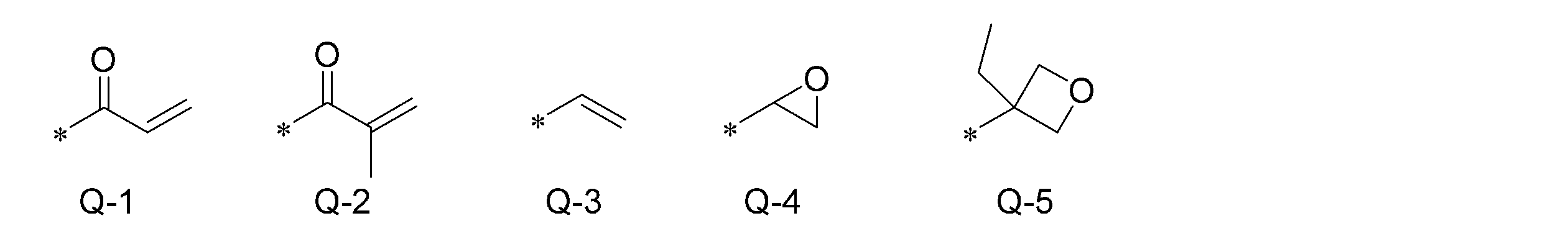
式(I)中の、フェニレン基は1,4-フェニレン基であることが好ましい。
フェニレン基およびトランス-1,4-シクロヘキシレン基について「置換基を有していてもよい」というときの置換基は、特に限定されず、例えば、アルキル基、シクロアルキル基、アルコキシ基、アルコキシカルボニル基、アミド基、アミノ基およびハロゲン原子、ならびに、上述の置換基を2つ以上組み合わせて構成される基が挙げられる。また、置換基の例としては、後述の-C(=O)-X3-Sp3-Q3で表される置換基が挙げられる。フェニレン基およびトランス-1,4-シクロヘキシレン基が置換基を有する場合、置換基を1~4個有していてもよい。2個以上の置換基を有するとき、2個以上の置換基は互いに同一であっても異なっていてもよい。 The phenylene group in formula (I) is preferably a 1,4-phenylene group.
Regarding the phenylene group and the trans-1,4-cyclohexylene group, the substituent when "optionally having a substituent" is not particularly limited. groups, amide groups, amino groups and halogen atoms, and groups composed of two or more of the above substituents in combination. Examples of substituents include substituents represented by -C(=O)-X 3 -Sp 3 -Q 3 described later. When the phenylene group and trans-1,4-cyclohexylene group have substituents, they may have 1 to 4 substituents. When having two or more substituents, the two or more substituents may be the same or different.
アルキル基は直鎖状および分岐鎖状のいずれでもよい。アルキル基の炭素数は1~30が好ましく、1~10がより好ましく、1~6がさらに好ましい。アルキル基の例としては、例えば、メチル基、エチル基、n-プロピル基、イソプロピル基、n-ブチル基、イソブチル基、sec-ブチル基、tert-ブチル基、n-ペンチル基、イソペンチル基、ネオペンチル基、1,1-ジメチルプロピル基、n-ヘキシル基及びイソヘキシル基、並びに、直鎖状または分岐鎖状である、ヘプチル基、オクチル基、ノニル基、デシル基、ウンデシル基及びドデシル基を挙げることができる。アルキル基に関する上述の説明はアルキル基を含むアルコキシ基及びアルコキシカルボニル基においても同様である。また、アルキレン基というときのアルキレン基の具体例としては、上述のアルキル基の例それぞれにおいて、任意の水素原子を1つ除いて得られる2価の基等が挙げられる。ハロゲン原子としては、フッ素原子、塩素原子、臭素原子およびヨウ素原子が挙げられる。
The alkyl group may be linear or branched. The number of carbon atoms in the alkyl group is preferably 1-30, more preferably 1-10, even more preferably 1-6. Examples of alkyl groups include methyl, ethyl, n-propyl, isopropyl, n-butyl, isobutyl, sec-butyl, tert-butyl, n-pentyl, isopentyl, and neopentyl. 1,1-dimethylpropyl, n-hexyl and isohexyl, and linear or branched heptyl, octyl, nonyl, decyl, undecyl and dodecyl can be done. The above description regarding alkyl groups also applies to alkoxy groups and alkoxycarbonyl groups containing alkyl groups. Further, specific examples of the alkylene group when referred to as an alkylene group include a divalent group obtained by removing one arbitrary hydrogen atom in each of the examples of the above-mentioned alkyl groups, and the like. Halogen atoms include fluorine, chlorine, bromine and iodine atoms.
シクロアルキル基の炭素数は、3~20が好ましく、下限値は5以上がより好ましく、また、上限値は10以下がより好ましく、8以下がさらに好ましく、6以下が特に好ましい。シクロアルキル基の例としては、シクロプロピル基、シクロブチル基、シクロペンチル基、シクロヘキシル基、シクロヘプチル基、シクロオクチル基を挙げることができる。
The number of carbon atoms in the cycloalkyl group is preferably 3 to 20, the lower limit is more preferably 5 or more, and the upper limit is more preferably 10 or less, more preferably 8 or less, and particularly preferably 6 or less. Examples of cycloalkyl groups include cyclopropyl, cyclobutyl, cyclopentyl, cyclohexyl, cycloheptyl and cyclooctyl groups.
フェニレン基およびトランス-1,4-シクロヘキシレン基が有していてもよい置換基としては特に、アルキル基、アルコキシ基、又は、-C(=O)-X3-Sp3-Q3が好ましい。ここで、X3は単結合、-O-、-S-、もしくは-N(Sp4-Q4)-を示すか、または、Q3およびSp3と共に環構造を形成している窒素原子を示す。Sp3およびSp4はそれぞれ独立に、単結合、炭素数1から20の直鎖もしくは分岐のアルキレン基、又は、炭素数1から20の直鎖もしくは分岐のアルキレン基において1つまたは2つ以上の-CH2-が-O-、-S-、-NH-、-N(CH3)-、-C(=O)-、-OC(=O)-及び-C(=O)O-から選択される基で置き換えられた基を示す。
As the substituent which the phenylene group and the trans-1,4-cyclohexylene group may have, an alkyl group, an alkoxy group, or -C(=O)-X 3 -Sp 3 -Q 3 is particularly preferable. . Here, X 3 represents a single bond, -O-, -S-, or -N(Sp 4 -Q 4 )-, or represents a nitrogen atom forming a ring structure together with Q 3 and Sp 3 show. Sp 3 and Sp 4 are each independently a single bond, a linear or branched alkylene group having 1 to 20 carbon atoms, or a linear or branched alkylene group having 1 to 20 carbon atoms, and 1 or 2 or more -CH 2 - from -O-, -S-, -NH-, -N(CH 3 )-, -C(=O)-, -OC(=O)- and -C(=O)O- Shows groups that have been replaced with selected groups.
Q3およびQ4はそれぞれ独立に、水素原子、シクロアルキル基、シクロアルキル基において1つもしくは2つ以上の-CH2-が-O-、-S-、-NH-、-N(CH3)-、-C(=O)-、-OC(=O)-及び-C(=O)O-から選択される基で置き換えられた基、または、式Q-1~式Q-5のいずれかで表される重合性基を示す。
Each of Q 3 and Q 4 is independently a hydrogen atom, a cycloalkyl group, or a cycloalkyl group in which one or more —CH 2 — is —O—, —S—, —NH—, —N(CH 3 )-, -C(=O)-, -OC(=O)- and -C(=O)O-, or a group selected from formulas Q-1 to Q-5 It shows a polymerizable group represented by any one.
シクロアルキル基において1つまたは2つ以上の-CH2-が-O-、-S-、-NH-、-N(CH3)-、-C(=O)-、-OC(=O)-及び-C(=O)O-から選択される基で置き換えられた基として、具体的には、テトラヒドロフラニル基、ピロリジニル基、イミダゾリジニル基、ピラゾリジニル基、ピペリジル基、ピペラジニル基、および、モルホルニル基等が挙げられる。置換位置は特に限定されない。これらのうち、テトラヒドロフラニル基が好ましく、特に2-テトラヒドロフラニル基が好ましい。
one or more -CH 2 - in the cycloalkyl group is -O-, -S-, -NH-, -N(CH 3 )-, -C(=O)-, -OC(=O) The group substituted with a group selected from - and -C(=O)O- specifically includes a tetrahydrofuranyl group, a pyrrolidinyl group, an imidazolidinyl group, a pyrazolidinyl group, a piperidyl group, a piperazinyl group, and a morphonyl group. etc. The substitution position is not particularly limited. Among these, a tetrahydrofuranyl group is preferred, and a 2-tetrahydrofuranyl group is particularly preferred.
式(I)において、Lは単結合、-CH2O-、-OCH2-、-(CH2)2OC(=O)-、-C(=O)O(CH2)2-、-C(=O)O-、-OC(=O)-、-OC(=O)O-、-CH=CH-C(=O)O-又は-OC(=O)-CH=CH-を示す。Lは-C(=O)O-または-OC(=O)-であることが好ましい。m-1個のLは互いに同一でも異なっていてもよい。
In formula (I), L is a single bond, -CH 2 O-, -OCH 2 -, -(CH 2 ) 2 OC(=O)-, -C(=O)O(CH 2 ) 2 -,- C(=O)O-, -OC(=O)-, -OC(=O)O-, -CH=CH-C(=O)O- or -OC(=O)-CH=CH- show. L is preferably -C(=O)O- or -OC(=O)-. m−1 Ls may be the same or different.
Sp1及びSp2はそれぞれ独立に、単結合、炭素数1から20の直鎖もしくは分岐のアルキレン基、又は、炭素数1から20の直鎖もしくは分岐のアルキレン基において1つまたは2つ以上の-CH2-が-O-、-S-、-NH-、-N(CH3)-、-C(=O)-、-OC(=O)-及び-C(=O)O-から選択される基で置き換えられた基を示す。
Sp1およびSp2はそれぞれ独立に、-OC(=O)-、-C(=O)O-、-O-、もしくは、炭素数1から10の直鎖のアルキレン基、又はこれらの基を2以上組み合わせて構成される連結基であることが好ましい。
-OC(=O)-、-C(=O)O-、-O-、もしくは、炭素数1から10の直鎖のアルキレン基を2以上組み合わせて構成される連結基としては、例えば、両末端にそれぞれ-O-、-OC(=O)-および-C(=O)O-から選択される連結基が結合した炭素数1から10の直鎖のアルキレン基(すなわち、炭素数1から10の直鎖のアルキレン基の両端に、-O-、-OC(=O)-又は-C(=O)O-がそれぞれ結合した基)が挙げられる。
Sp1およびSp2は、炭素数1から10の直鎖のアルキレン基の両端のうち、Q1又はQ2に結合する側の末端に-O-が結合し、他方の末端に-O-、-OC(=O)-又は-C(=O)O-が結合した基であることがより好ましい。 Sp 1 and Sp 2 are each independently a single bond, a linear or branched alkylene group having 1 to 20 carbon atoms, or a linear or branched alkylene group having 1 to 20 carbon atoms, and 1 or 2 or more -CH 2 - from -O-, -S-, -NH-, -N(CH 3 )-, -C(=O)-, -OC(=O)- and -C(=O)O- Shows groups that have been replaced with selected groups.
Sp 1 and Sp 2 are each independently -OC(=O)-, -C(=O)O-, -O-, or a linear alkylene group having 1 to 10 carbon atoms, or these groups A linking group formed by combining two or more groups is preferred.
-OC(=O)-, -C(=O)O-, -O-, or a linking group formed by combining two or more linear alkylene groups having 1 to 10 carbon atoms, for example, both A straight-chain alkylene group having 1 to 10 carbon atoms (i.e., 1 to 1 A group in which -O-, -OC(=O)- or -C(=O)O- is bonded to both ends of a linear alkylene group of 10).
Sp 1 and Sp 2 are straight-chain alkylene groups having 1 to 10 carbon atoms, wherein —O— is attached to the end on the side that is bonded to Q 1 or Q 2 , and —O—, A group to which -OC(=O)- or -C(=O)O- is bonded is more preferable.
Q1およびQ2はそれぞれ独立に、水素原子、もしくは上述の式Q-1~式Q-5のいずれかで表される重合性基を示す。ただしQ1およびQ2の少なくともいずれか一方は重合性基を示し、共に重合性基であることが好ましい。
重合性基としては、アクリロイル基(式Q-1)またはメタクリロイル基(式Q-2)が好ましい。 Q 1 and Q 2 each independently represent a hydrogen atom or a polymerizable group represented by any one of the above formulas Q-1 to Q-5. However, at least one of Q 1 and Q 2 represents a polymerizable group, and both are preferably polymerizable groups.
As the polymerizable group, an acryloyl group (formula Q-1) or a methacryloyl group (formula Q-2) is preferred.
式(I)中、mは、3~12の整数を示す。mは、3~9の整数が好ましく、3~7の整数がより好ましく、3~5の整数がさらに好ましい。
In formula (I), m represents an integer of 3-12. m is preferably an integer of 3 to 9, more preferably an integer of 3 to 7, and even more preferably an integer of 3 to 5.
式(I)で表される重合性化合物は、Aとして置換基を有していてもよいフェニレン基を少なくとも1つおよび置換基を有していてもよいトランス-1,4-シクロヘキシレン基を少なくとも1つを含むことが好ましい。
式(I)で表される重合性化合物は、Aとして、置換基を有していてもよいトランス-1,4-シクロヘキシレン基を1~4個含むことが好ましく、1~3個含むことがより好ましい。また、式(I)で表される重合性化合物は、Aとして、置換基を有していてもよいフェニレン基を1個以上含むことが好ましく、1~4個含むことがより好ましい。 The polymerizable compound represented by formula (I) has at least one optionally substituted phenylene group as A and an optionally substituted trans-1,4-cyclohexylene group. It preferably contains at least one.
The polymerizable compound represented by formula (I) preferably contains 1 to 4 optionally substituted trans-1,4-cyclohexylene groups as A, and preferably contains 1 to 3 groups. is more preferred. In addition, the polymerizable compound represented by formula (I) preferably contains one or more optionally substituted phenylene groups as A, more preferably 1 to 4 groups.
式(I)において、Aで表されるトランス-1,4-シクロヘキシレン基の数をmで割った数をmcとしたとき、0.1<mc<0.9が好ましく、0.3<mc<0.8がより好ましく、0.5<mc<0.7がさらに好ましい。液晶組成物が0.5<mc<0.7である式(I)で表される重合性化合物とともに、0.1<mc<0.3である式(I)で表される重合性化合物を含むことも好ましい。
In formula (I), when mc is the number obtained by dividing the number of trans-1,4-cyclohexylene groups represented by A by m, 0.1<mc<0.9 is preferable, and 0.3< mc<0.8 is more preferred, and 0.5<mc<0.7 is even more preferred. The polymerizable compound represented by the formula (I) having a liquid crystal composition satisfying 0.5<mc<0.7 and the polymerizable compound represented by the formula (I) satisfying 0.1<mc<0.3 It is also preferred to include
式(I)で表される重合性化合物の例として具体的には、WO2016/047648の段落0051~0058に記載の化合物のほか、特開2013-112631号公報、特開2010-070543号公報、特許4725516号、WO2015/115390、WO2015/147243、WO2016/035873、特開2015-163596号公報、および、特開2016-053149号公報に記載の化合物等を挙げることができる。
Specific examples of the polymerizable compound represented by formula (I) include, in addition to the compounds described in paragraphs 0051 to 0058 of WO2016/047648, JP-A-2013-112631, JP-A-2010-070543, Japanese Patent No. 4725516, WO2015/115390, WO2015/147243, WO2016/035873, JP-A-2015-163596, and compounds described in JP-A-2016-053149.
低Δnのコレステリック液晶層を形成する液晶組成物中には、上述の式(I)で表される重合性化合物以外の重合性液晶化合物(以下、その他の重合性液晶化合物と称す。)を含有していてもよい。
その他の重合性液晶化合物としては、前述の重合性液晶化合物の例として記載する化合物のうち、上述の式(I)で表される重合性化合物以外の重合性液晶化合物を挙げることができる。
低Δnのコレステリック液晶層を形成する液晶組成物において、重合性液晶化合物の総量に占める上述の式(I)で表される重合性化合物の割合は、30~100質量%が好ましく、50~100質量%がより好ましく、70~100質量%がさらに好ましい。 The liquid crystal composition forming the low Δn cholesteric liquid crystal layer contains polymerizable liquid crystal compounds other than the polymerizable compound represented by the formula (I) (hereinafter referred to as other polymerizable liquid crystal compounds). You may have
Examples of other polymerizable liquid crystal compounds include polymerizable liquid crystal compounds other than the polymerizable compound represented by the above formula (I) among the compounds described as examples of the polymerizable liquid crystal compound.
In the liquid crystal composition that forms a cholesteric liquid crystal layer with a low Δn, the proportion of the polymerizable compound represented by the above formula (I) in the total amount of polymerizable liquid crystal compounds is preferably 30 to 100% by mass, more preferably 50 to 100%. % by mass is more preferred, and 70 to 100% by mass is even more preferred.
(キラル剤:光学活性化合物)
キラル剤はコレステリック液晶相の螺旋構造を誘起する機能を有する。キラル化合物は、化合物によって誘起する螺旋のセンスまたは螺旋ピッチが異なるため、目的に応じて選択すればよい。
キラル剤としては、特に制限はなく、常用の化合物を用いることができる。キラル剤の例としては、液晶デバイスハンドブック(第3章4-3項、TN、STN用カイラル剤、199頁、日本学術振興会第142委員会編、1989)、特開2003-287623号、特開2002-302487号、特開2002-080478号、特開2002-080851号、特開2010-181852号、および、特開2014-034581号等の各公報に記載の化合物が挙げられる。 (Chiral Agent: Optically Active Compound)
A chiral agent has a function of inducing a helical structure of a cholesteric liquid crystal phase. The chiral compound may be selected according to the purpose, since the helical sense or helical pitch induced by the compound differs.
The chiral agent is not particularly limited, and commonly used compounds can be used. Examples of chiral agents include Liquid Crystal Device Handbook (Chapter 3, Section 4-3, Chiral Agents for TN and STN, p. Examples include compounds described in JP-A-2002-302487, JP-A-2002-080478, JP-A-2002-080851, JP-A-2010-181852, and JP-A-2014-034581.
キラル剤は、一般に不斉炭素原子を含むが、不斉炭素原子を含まない軸性不斉化合物あるいは面性不斉化合物も、キラル剤として用いることができる。軸性不斉化合物または面性不斉化合物の例には、ビナフチル、ヘリセン、パラシクロファン、および、これらの誘導体が含まれる。
キラル剤は、重合性基を有していてもよい。キラル剤と液晶化合物とがいずれも重合性基を有する場合は、重合性キラル剤と重合性液晶化合物との重合反応により、重合性液晶化合物から誘導される繰り返し単位と、キラル剤から誘導される繰り返し単位とを有するポリマーを形成することができる。この態様では、重合性キラル剤が有する重合性基は、重合性液晶化合物が有する重合性基と、同種の基であることが好ましい。従って、キラル剤の重合性基も、不飽和重合性基、エポキシ基またはアジリジニル基であることが好ましく、不飽和重合性基であることがより好ましく、エチレン性不飽和重合性基であることがさらに好ましい。
また、キラル剤は、液晶化合物であってもよい。 A chiral agent generally contains an asymmetric carbon atom, but an axially chiral compound or planar asymmetric compound that does not contain an asymmetric carbon atom can also be used as a chiral agent. Examples of axially or planarly chiral compounds include binaphthyl, helicene, paracyclophane, and derivatives thereof.
The chiral agent may have a polymerizable group. When both the chiral agent and the liquid crystal compound have a polymerizable group, a repeating unit derived from the polymerizable liquid crystal compound and a repeating unit derived from the chiral agent are formed by the polymerization reaction of the polymerizable chiral agent and the polymerizable liquid crystal compound. A polymer having repeating units can be formed. In this aspect, the polymerizable group possessed by the polymerizable chiral agent is preferably the same type of group as the polymerizable group possessed by the polymerizable liquid crystal compound. Therefore, the polymerizable group of the chiral agent is also preferably an unsaturated polymerizable group, an epoxy group or an aziridinyl group, more preferably an unsaturated polymerizable group, and an ethylenically unsaturated polymerizable group. More preferred.
Also, the chiral agent may be a liquid crystal compound.
キラル剤としては、イソソルビド誘導体、イソマンニド誘導体、および、ビナフチル誘導体等を好ましく用いることができる。イソソルビド誘導体としては、BASF社製のLC756(商品名)等の市販品を用いてもよい。
液晶組成物における、キラル剤の含有量は、重合性液晶化合物量の0.01~200モル%が好ましく、1~30モル%がより好ましい。 As the chiral agent, isosorbide derivatives, isomannide derivatives, binaphthyl derivatives and the like can be preferably used. As the isosorbide derivative, a commercially available product such as LC756 (trade name) manufactured by BASF may be used.
The content of the chiral agent in the liquid crystal composition is preferably 0.01 to 200 mol %, more preferably 1 to 30 mol % of the amount of the polymerizable liquid crystal compound.
また、前述のとおり、上記直線偏光反射フィルムが有する選択反射層のコレステリック液晶層は、2以上の選択反射中心波長を有するものであってもよい。2以上の選択反射中心波長を有するコレステリック液晶層は、螺旋構造のピッチを厚み方向に変化させることで達成される。螺旋構造のピッチが厚み方向に変化するコレステリック液晶層は、光の照射によって、螺旋誘起力(HTP:Helical Twisting Power)が変化するキラル剤を用いて、コレステリック液晶層を形成する際に、厚さ方向に光の照射量を変えることによって作製することができる。
Further, as described above, the cholesteric liquid crystal layer of the selective reflection layer of the linearly polarized light reflection film may have two or more selective reflection central wavelengths. A cholesteric liquid crystal layer having two or more selective reflection central wavelengths is achieved by changing the pitch of the helical structure in the thickness direction. The cholesteric liquid crystal layer, in which the pitch of the helical structure changes in the thickness direction, is formed by using a chiral agent whose helical twisting power (HTP) changes when irradiated with light. It can be produced by changing the irradiation amount of light in the direction.
光の照射によってHTPが変化するキラル剤は、光の照射によって、戻り異性化、二量化、ならびに、異性化および二量化等を生じるものが挙げられる。
キラル剤が光異性化基を有する場合の、光異性化基としては、フォトクロッミック性を示す化合物の異性化部位、アゾ基、アゾキシ基、または、シンナモイル基が好ましい。具体的な化合物として、特開2002-080478号公報、特開2002-080851号公報、特開2002-179668号公報、特開2002-179669号公報、特開2002-179670号公報、特開2002-179681号公報、特開2002-179682号公報、特開2002-338575号公報、特開2002-338668号公報、特開2003-313189号公報、および、特開2003-313292号公報等に記載の化合物を用いることができる。 Chiral agents whose HTP is changed by light irradiation include those that undergo re-isomerization, dimerization, isomerization and dimerization, etc. by light irradiation.
When the chiral agent has a photoisomerizable group, the photoisomerizable group is preferably an isomerization site of a compound exhibiting photochromic properties, an azo group, an azoxy group, or a cinnamoyl group. Specific compounds include JP-A-2002-080478, JP-A-2002-080851, JP-A-2002-179668, JP-A-2002-179669, JP-A-2002-179670, JP-A-2002- 179681, JP-A-2002-179682, JP-A-2002-338575, JP-A-2002-338668, JP-A-2003-313189, and compounds described in JP-A-2003-313292, etc. can be used.
(重合開始剤)
液晶組成物は、重合開始剤を含有していることが好ましい。紫外線照射により重合反応を進行させる態様では、使用する重合開始剤は、紫外線照射によって重合反応を開始可能な光重合開始剤であることが好ましい。
光重合開始剤の例には、α-カルボニル化合物(米国特許第2367661号、米国特許第2367670号の各明細書記載)、アシロインエーテル化合物(米国特許第2448828号明細書記載)、α-炭化水素置換芳香族アシロイン化合物(米国特許第2722512号明細書記載)、多核キノン化合物(米国特許第3046127号、米国特許第2951758号の各明細書記載)、トリアリールイミダゾールダイマーとp-アミノフェニルケトンとの組み合わせ(米国特許第3549367号明細書記載)、アクリジンおよびフェナジン化合物(特開昭60-105667号公報、米国特許第4239850号明細書記載)、アシルフォスフィンオキシド化合物(特公昭63-040799号公報、特公平5-029234号公報、特開平10-095788号公報、特開平10-029997号公報、特開2001-233842号公報、特開2000-080068号公報、特開2006-342166号公報、特開2013-114249号公報、特開2014-137466号公報、特許4223071号公報、特開2010-262028号公報、特表2014-500852号公報記載)、オキシム化合物(特開2000-066385号公報、特許第4454067号公報記載)、および、オキサジアゾール化合物(米国特許第4212970号明細書記載)等が挙げられる。例えば、特開2012-208494号公報の段落0500~0547の記載も参酌できる。 (Polymerization initiator)
The liquid crystal composition preferably contains a polymerization initiator. In the embodiment in which the polymerization reaction is advanced by ultraviolet irradiation, the polymerization initiator to be used is preferably a photopolymerization initiator capable of initiating the polymerization reaction by ultraviolet irradiation.
Examples of photoinitiators include α-carbonyl compounds (described in US Pat. Nos. 2,367,661 and 2,367,670), acyloin ether compounds (described in US Pat. No. 2,448,828), α-carbon A hydrogen-substituted aromatic acyloin compound (described in US Pat. No. 2,722,512), a polynuclear quinone compound (described in US Pat. Nos. 3,046,127 and 2,951,758), a triarylimidazole dimer and p-aminophenyl ketone (described in US Pat. No. 3,549,367), acridine and phenazine compounds (described in JP-A-60-105667, US Pat. No. 4,239,850), acylphosphine oxide compounds (JP-B-63-040799) , JP-B-5-029234, JP-A-10-095788, JP-A-10-029997, JP-A-2001-233842, JP-A-2000-080068, JP-A-2006-342166, Patent JP 2013-114249, JP 2014-137466, JP 4223071, JP 2010-262028, JP 2014-500852), oxime compound (JP 2000-066385, patent No. 4,454,067) and oxadiazole compounds (described in US Pat. No. 4,212,970). For example, paragraphs 0500 to 0547 of JP-A-2012-208494 can also be referred to.
重合開始剤としては、アシルフォスフィンオキシド化合物またはオキシム化合物を用いることも好ましい。
アシルフォスフィンオキシド化合物としては、例えば、市販品のBASFジャパン(株)製のIRGACURE810(商品名、化合物名:ビス(2,4,6-トリメチルベンゾイル)-フェニルフォスフィンオキサイド)を用いることができる。オキシム化合物としては、IRGACURE OXE01(商品名、BASF社製)、IRGACURE OXE02(商品名、BASF社製)、TR-PBG-304(商品名、常州強力電子新材料有限公司製)、アデカアークルズNCI-930(商品名、ADEKA社製)、アデカアークルズNCI-831(商品名、ADEKA社製)等の市販品を用いることができる。
重合開始剤は、1種のみ用いてもよいし、2種以上を併用してもよい。
液晶組成物中の光重合開始剤の含有量は、重合性液晶化合物の含有量に対して0.1~20質量%が好ましく、0.5~5質量%がより好ましい。 As the polymerization initiator, it is also preferable to use an acylphosphine oxide compound or an oxime compound.
As the acylphosphine oxide compound, for example, a commercially available product, IRGACURE810 (trade name, compound name: bis(2,4,6-trimethylbenzoyl)-phenylphosphine oxide) manufactured by BASF Japan Ltd. can be used. . Examples of oxime compounds include IRGACURE OXE01 (trade name, manufactured by BASF), IRGACURE OXE02 (trade name, manufactured by BASF), TR-PBG-304 (trade name, manufactured by Changzhou Tenryu Electric New Materials Co., Ltd.), and Adeka Arcles NCI. -930 (trade name, manufactured by ADEKA), ADEKA Arkles NCI-831 (trade name, manufactured by ADEKA), and other commercial products can be used.
Only one polymerization initiator may be used, or two or more polymerization initiators may be used in combination.
The content of the photopolymerization initiator in the liquid crystal composition is preferably 0.1 to 20% by mass, more preferably 0.5 to 5% by mass, based on the content of the polymerizable liquid crystal compound.
(架橋剤)
液晶組成物は、硬化後の膜強度向上、耐久性向上のため、任意に架橋剤を含有していてもよい。架橋剤としては、紫外線、熱、湿気等で硬化するものが好適に使用できる。
架橋剤としては、特に制限はなく、目的に応じて適宜選択することができる。架橋剤としては、例えば、トリメチロールプロパントリ(メタ)アクリレート、ペンタエリスリトールトリ(メタ)アクリレート等の多官能アクリレート化合物;グリシジル(メタ)アクリレート、エチレングリコールジグリシジルエーテル等のエポキシ化合物;2,2-ビスヒドロキシメチルブタノール-トリス[3-(1-アジリジニル)プロピオネート]、4,4-ビス(エチレンイミノカルボニルアミノ)ジフェニルメタン等のアジリジン化合物;ヘキサメチレンジイソシアネート、ビウレット型イソシアネート等のイソシアネート化合物;オキサゾリン基を側鎖に有するポリオキサゾリン化合物;ビニルトリメトキシシラン、N-(2-アミノエチル)3-アミノプロピルトリメトキシシラン等のアルコキシシラン化合物等が挙げられる。また、架橋剤の反応性に応じて常用の触媒を用いることができ、膜強度および耐久性向上に加えて生産性を向上させることができる。これらは、1種単独で使用してもよいし、2種以上を併用してもよい。
液晶組成物中の架橋剤の含有量は、液晶組成物の固形分質量(溶媒を除いた質量)に対して、3~20質量%が好ましく、5~15質量%がより好ましい。架橋剤の含有量を3質量%以上とすることにより、架橋密度向上の効果を得ることができ、架橋剤の含有量を20質量%以下とすることにより、コレステリック液晶層の安定性の低下を防止できる。
なお、「(メタ)アクリレート」は、「アクリレートおよびメタクリレートのいずれか一方または双方」の意味で使用される。 (crosslinking agent)
The liquid crystal composition may optionally contain a cross-linking agent in order to improve film strength and durability after curing. As the cross-linking agent, one that is cured by ultraviolet rays, heat, humidity, or the like can be preferably used.
The cross-linking agent is not particularly limited and can be appropriately selected depending on the purpose. Examples of cross-linking agents include polyfunctional acrylate compounds such as trimethylolpropane tri (meth) acrylate and pentaerythritol tri (meth) acrylate; epoxy compounds such as glycidyl (meth) acrylate and ethylene glycol diglycidyl ether; aziridine compounds such as bishydroxymethylbutanol-tris[3-(1-aziridinyl)propionate], 4,4-bis(ethyleneiminocarbonylamino)diphenylmethane; isocyanate compounds such as hexamethylene diisocyanate and biuret type isocyanate; polyoxazoline compounds having chains; alkoxysilane compounds such as vinyltrimethoxysilane and N-(2-aminoethyl)3-aminopropyltrimethoxysilane; In addition, a commonly used catalyst can be used depending on the reactivity of the cross-linking agent, and productivity can be improved in addition to improvement in film strength and durability. These may be used individually by 1 type, and may use 2 or more types together.
The content of the cross-linking agent in the liquid crystal composition is preferably 3 to 20% by mass, more preferably 5 to 15% by mass, based on the solid mass (mass excluding the solvent) of the liquid crystal composition. By setting the content of the cross-linking agent to 3% by mass or more, the effect of improving the cross-linking density can be obtained, and by setting the content of the cross-linking agent to 20% by mass or less, the decrease in stability of the cholesteric liquid crystal layer can be prevented. can be prevented.
In addition, "(meth)acrylate" is used in the sense of "one or both of acrylate and methacrylate".
(配向制御剤)
液晶組成物中には、安定的にまたは迅速にプレーナー配向のコレステリック液晶層とするために寄与する配向制御剤を添加してもよい。配向制御剤の例としては、特開2007-272185号公報の段落[0018]~[0043]等に記載のフッ素(メタ)アクリレート系ポリマー、特開2012-203237号公報の段落[0031]~[0034]等に記載の式(I)~(IV)で表される化合物、および、特開2013-113913号公報に記載の化合物等が挙げられる。
なお、配向制御剤としては1種を単独で用いてもよいし、2種以上を併用してもよい。 (Orientation control agent)
An alignment control agent may be added to the liquid crystal composition to contribute to stably or rapidly forming a planar alignment cholesteric liquid crystal layer. Examples of alignment control agents include fluorine (meth)acrylate polymers described in paragraphs [0018] to [0043] of JP-A-2007-272185, paragraphs [0031] to [0031] of JP-A-2012-203237. 0034] and the like, compounds represented by formulas (I) to (IV), and compounds described in JP-A-2013-113913.
As the alignment control agent, one type may be used alone, or two or more types may be used in combination.
液晶組成物中における、配向制御剤の添加量は、重合性液晶化合物の全質量に対して0.01~10質量%が好ましく、0.01~5質量%がより好ましく、0.02~1質量%が特に好ましい。
The amount of the alignment control agent added in the liquid crystal composition is preferably 0.01 to 10% by mass, more preferably 0.01 to 5% by mass, and more preferably 0.02 to 1% based on the total mass of the polymerizable liquid crystal compound. % by weight is particularly preferred.
(その他の添加剤)
その他、液晶組成物は、塗膜の表面張力を調整し厚さを均一にするための界面活性剤、および重合性モノマー等の種々の添加剤から選ばれる少なくとも1種を含有していてもよい。また、液晶組成物中には、必要に応じて、さらに重合禁止剤、酸化防止剤、紫外線吸収剤、光安定化剤、色材、および、金属酸化物微粒子等を、光学性能を低下させない範囲で添加することができる。 (Other additives)
In addition, the liquid crystal composition may contain at least one selected from various additives such as a surfactant for adjusting the surface tension of the coating film to make the thickness uniform, and a polymerizable monomer. . In addition, if necessary, the liquid crystal composition may further contain polymerization inhibitors, antioxidants, ultraviolet absorbers, light stabilizers, colorants, metal oxide fine particles, etc. to the extent that the optical performance is not reduced. can be added at
コレステリック液晶層は、重合性液晶化合物および重合開始剤、更に必要に応じて添加されるキラル剤、界面活性剤等を溶媒に溶解させた液晶組成物を、透明基材、位相差層、配向層、または、先に作製されたコレステリック液晶層等の上に塗布し、乾燥させて塗膜を得、この塗膜に活性光線を照射してコレステリック液晶性組成物を重合し、コレステリック規則性が固定化されたコレステリック液晶層を形成することができる。
なお、複数のコレステリック液晶層からなる積層膜は、コレステリック液晶層の上述の製造工程を繰り返し行うことにより形成することができる。 The cholesteric liquid crystal layer comprises a liquid crystal composition obtained by dissolving a polymerizable liquid crystal compound, a polymerization initiator, a chiral agent, a surfactant, etc. added as necessary in a solvent, a transparent substrate, a retardation layer, and an alignment layer. Alternatively, it is coated on the previously prepared cholesteric liquid crystal layer or the like, dried to obtain a coating film, and the coating film is irradiated with actinic rays to polymerize the cholesteric liquid crystal composition, and the cholesteric regularity is fixed. cholesteric liquid crystal layer can be formed.
A laminated film composed of a plurality of cholesteric liquid crystal layers can be formed by repeating the above-described manufacturing process of the cholesteric liquid crystal layer.
(溶媒)
液晶組成物の調製に使用する溶媒には、特に制限はなく、目的に応じて適宜選択することができるが、有機溶媒が好ましく用いられる。
有機溶媒には、特に制限はなく、目的に応じて適宜選択することができ、例えば、ケトン類、アルキルハライド類、アミド類、スルホキシド類、ヘテロ環化合物、炭化水素類、エステル類、および、エーテル類等が挙げられる。これらは、1種単独で使用してもよいし、2種以上を併用してもよい。これらの中でも、環境への負荷を考慮した場合にはケトン類が特に好ましい。 (solvent)
The solvent used for preparing the liquid crystal composition is not particularly limited and can be appropriately selected depending on the intended purpose, but an organic solvent is preferably used.
The organic solvent is not particularly limited and can be appropriately selected depending on the purpose. Examples include ketones, alkyl halides, amides, sulfoxides, heterocyclic compounds, hydrocarbons, esters and ethers. and the like. These may be used individually by 1 type, and may use 2 or more types together. Among these, ketones are particularly preferable in consideration of the load on the environment.
(塗布、配向、重合)
透明基材、配向層、下層となるコレステリック液晶層等への液晶組成物の塗布方法には、特に制限はなく、目的に応じて適宜選択することができる。塗布方法としては、例えば、ワイヤーバーコーティング法、カーテンコーティング法、押し出しコーティング法、ダイレクトグラビアコーティング法、リバースグラビアコーティング法、ダイコーティング法、スピンコーティング法、ディップコーティング法、スプレーコーティング法、および、スライドコーティング法等が挙げられる。また、別途支持体上に塗設した液晶組成物を転写することによっても実施できる。
塗布した液晶組成物を加熱することにより、液晶分子を配向させる。加熱温度は、200℃以下が好ましく、130℃以下がより好ましい。この配向処理により、重合性液晶化合物が、フィルム面に対して実質的に垂直な方向に螺旋軸を有するようにねじれ配向している光学薄膜が得られる。 (coating, orientation, polymerization)
The method of applying the liquid crystal composition to the transparent substrate, the alignment layer, the underlying cholesteric liquid crystal layer, and the like is not particularly limited, and can be appropriately selected according to the purpose. Examples of coating methods include wire bar coating, curtain coating, extrusion coating, direct gravure coating, reverse gravure coating, die coating, spin coating, dip coating, spray coating, and slide coating. law, etc. It can also be carried out by transferring a liquid crystal composition separately coated on a support.
The liquid crystal molecules are aligned by heating the applied liquid crystal composition. The heating temperature is preferably 200° C. or lower, more preferably 130° C. or lower. By this orientation treatment, an optical thin film is obtained in which the polymerizable liquid crystal compound is twisted so as to have a helical axis in a direction substantially perpendicular to the film surface.
配向させた液晶化合物をさらに重合させることにより、液晶組成物を硬化することができる。重合は、熱重合、光照射を利用する光重合のいずれでもよいが、光重合が好ましい。光照射は、紫外線を用いることが好ましい。照射エネルギーは、20mJ/cm2~50J/cm2が好ましく、100~1,500mJ/cm2がより好ましい。
光重合反応を促進するため、加熱条件下または窒素雰囲気下で光照射を実施してもよい。照射紫外線波長は350~430nmが好ましい。重合反応率は安定性の観点から、高いほうが好ましく、具体的には、70%以上が好ましく、80%以上がより好ましい。重合反応率は、重合性の官能基の消費割合を赤外線吸収スペクトルの測定により、決定することができる。 By further polymerizing the oriented liquid crystal compound, the liquid crystal composition can be cured. Polymerization may be either thermal polymerization or photopolymerization using light irradiation, but photopolymerization is preferred. It is preferable to use ultraviolet rays for light irradiation. The irradiation energy is preferably 20 mJ/cm 2 to 50 J/cm 2 , more preferably 100 to 1,500 mJ/cm 2 .
In order to accelerate the photopolymerization reaction, light irradiation may be performed under heating conditions or under a nitrogen atmosphere. The irradiation ultraviolet wavelength is preferably 350 to 430 nm. From the viewpoint of stability, the polymerization reaction rate is preferably as high as possible. Specifically, it is preferably 70% or more, more preferably 80% or more. The polymerization reaction rate can be determined by measuring the consumption rate of the polymerizable functional groups by infrared absorption spectrum measurement.
〔偏光変換層〕
偏光変換層14は、液晶化合物の螺旋配向構造を固定化した層であって、螺旋配向構造のピッチ数xおよび偏光変換層の膜厚y(単位μm)が下記関係式(a)~(c)の全てを満足するものであるのが好ましい。
0.1≦x≦1.0 ・・・ 式(a)
0.5≦y≦3.0 ・・・ 式(b)
3000≦(1560×y)/x≦50000 ・・・ 式(c)
なお、液晶化合物の螺旋構造の1ピッチは、液晶化合物の螺旋の巻き数1回分である。
すなわち、螺旋配向される液晶化合物のダイレクター(棒状液晶であれば長軸方向)が、360°回転した状態をピッチ数1とする。 [Polarization conversion layer]
Thepolarization conversion layer 14 is a layer in which the helical orientation structure of the liquid crystal compound is fixed, and the pitch number x of the helical orientation structure and the film thickness y (unit μm) of the polarization conversion layer satisfy the following relational expressions (a) to (c ) are preferably satisfied.
0.1≦x≦1.0 Formula (a)
0.5≦y≦3.0 Formula (b)
3000≦(1560×y)/x≦50000 Expression (c)
Note that one pitch of the helical structure of the liquid crystal compound is one turn of the helical structure of the liquid crystal compound.
That is, the pitch number is 1 when the director of the helically aligned liquid crystal compound (long axis direction in the case of rod-like liquid crystal) is rotated by 360°.
偏光変換層14は、液晶化合物の螺旋配向構造を固定化した層であって、螺旋配向構造のピッチ数xおよび偏光変換層の膜厚y(単位μm)が下記関係式(a)~(c)の全てを満足するものであるのが好ましい。
0.1≦x≦1.0 ・・・ 式(a)
0.5≦y≦3.0 ・・・ 式(b)
3000≦(1560×y)/x≦50000 ・・・ 式(c)
なお、液晶化合物の螺旋構造の1ピッチは、液晶化合物の螺旋の巻き数1回分である。
すなわち、螺旋配向される液晶化合物のダイレクター(棒状液晶であれば長軸方向)が、360°回転した状態をピッチ数1とする。 [Polarization conversion layer]
The
0.1≦x≦1.0 Formula (a)
0.5≦y≦3.0 Formula (b)
3000≦(1560×y)/x≦50000 Expression (c)
Note that one pitch of the helical structure of the liquid crystal compound is one turn of the helical structure of the liquid crystal compound.
That is, the pitch number is 1 when the director of the helically aligned liquid crystal compound (long axis direction in the case of rod-like liquid crystal) is rotated by 360°.
偏光変換層は液晶化合物の螺旋構造を有していると、赤外域の反射ピーク波長よりも短波長である可視光に対して旋光性と複屈折性を示す。そのため、可視域の偏光を制御できる。偏光変換層の螺旋配向構造のピッチ数xおよび偏光変換層の膜厚yを上記の範囲とすることで、可視光に対して偏光変換層で光学補償する機能、あるいは、反射フィルムに入射した直線偏光(p偏光)を円偏光に変換する機能を付与することができる。
When the polarization conversion layer has a helical structure of a liquid crystal compound, it exhibits optical rotation and birefringence with respect to visible light whose wavelength is shorter than the reflection peak wavelength in the infrared region. Therefore, polarization in the visible range can be controlled. By setting the pitch number x of the helically oriented structure of the polarization conversion layer and the film thickness y of the polarization conversion layer within the above ranges, the polarization conversion layer has a function of optically compensating for visible light, or a straight line incident on the reflective film. A function of converting polarized light (p-polarized light) into circularly polarized light can be imparted.
偏光変換層は、液晶化合物が、関係式(a)~(c)を満たす螺旋構造を有することにより、可視光に対して旋光性および複屈折性を示す。特に、偏光変換層の螺旋構造のピッチPを、選択反射中心波長が長波長の赤外域であるコレステリック液晶層のピッチPに対応する長さとすることにより、短波長である可視光に対して、高い旋光性と複屈折性を示す。
The polarization conversion layer exhibits optical rotation and birefringence with respect to visible light due to the liquid crystal compound having a helical structure that satisfies the relational expressions (a) to (c). In particular, by setting the pitch P of the helical structure of the polarization conversion layer to a length corresponding to the pitch P of the cholesteric liquid crystal layer whose selective reflection center wavelength is in the infrared region with a long wavelength, for visible light with a short wavelength, It exhibits high optical rotation and birefringence.
関係式(a)は、『0.1≦x≦1.0』である。
螺旋構造のピッチ数xが0.1未満では、十分な旋光性および複屈折性が得られない等の不都合を生じる。
また、螺旋構造のピッチ数xが1.0を超えると、旋光性および複屈折性が過剰で、所望の楕円偏光が得られない等の不都合を生じる。 The relational expression (a) is "0.1≤x≤1.0".
If the pitch number x of the helical structure is less than 0.1, problems such as insufficient optical rotation and birefringence will occur.
On the other hand, if the pitch number x of the helical structure exceeds 1.0, the optical rotatory power and birefringence are excessive, resulting in problems such as failure to obtain desired elliptically polarized light.
関係式(b)は、『0.5≦y≦3.0』である。
偏光変換層の厚さyが0.5μm未満では、膜厚が薄すぎて、十分な旋光性および複屈折性が得られない等の不都合を生じる。
偏光変換層の厚さyが3.0μmを超えると、旋光性および複屈折性が過剰で、所望の円偏光が得られない、配向不良が起こりやすく製造にとって好ましくない等の不都合を生じる。 The relational expression (b) is "0.5≤y≤3.0".
If the thickness y of the polarization conversion layer is less than 0.5 μm, the film thickness is too thin, resulting in problems such as insufficient optical rotation and birefringence.
If the thickness y of the polarization conversion layer exceeds 3.0 μm, the optical rotation and birefringence are excessive, resulting in problems such as failure to obtain desired circularly polarized light and poor orientation, which is undesirable for manufacturing.
関係式(c)は、『3000≦(1560×y)/x≦50000』である。
「(1560×y)/x」が3000未満では、旋光性が過剰で所望の偏光が得られない等の不都合が生じる。
「(1560×y)/x」が50000を超えると、旋光性が不足し、所望の偏光が得られない等の不都合を生じる。 The relational expression (c) is "3000≦(1560×y)/x≦50000".
If “(1560×y)/x” is less than 3000, the optical rotatory power is excessive and the desired polarized light cannot be obtained.
If “(1560×y)/x” exceeds 50000, the optical rotatory power is insufficient, resulting in problems such as failure to obtain desired polarized light.
本発明において、偏光変換層の螺旋構造のピッチ数xは、0.1~0.8がより好ましく、膜厚yは、0.6μm~2.6μmがより好ましい。また、「(1560×y)/x」は、5000~13000がより好ましい。
In the present invention, the pitch number x of the helical structure of the polarization conversion layer is more preferably 0.1 to 0.8, and the film thickness y is more preferably 0.6 μm to 2.6 μm. Further, "(1560×y)/x" is more preferably 5000 to 13000.
すなわち、偏光変換層は、螺旋構造のピッチPが長く、かつ、ピッチ数xが少ないのが好ましい。
具体的には、偏光変換層は、螺旋のピッチPが、選択反射中心波長が長波長の赤外域であるコレステリック液晶層のピッチPと同等で、かつ、ピッチ数xが少ないのが好ましい。より具体的には、偏光変換層は、螺旋のピッチPが、選択反射中心波長が3000~10000nmであるコレステリック液晶層のピッチPと同等で、かつ、ピッチ数xが少ないのが好ましい。
このような偏光変換層は、ピッチPが対応する選択反射中心波長が、可視光よりも遥かに長波長であるため、上述した可視光に対する旋光性と複屈折性を、より好適に発現する。 That is, the polarization conversion layer preferably has a long spiral structure pitch P and a small pitch number x.
Specifically, the polarization conversion layer preferably has a spiral pitch P equal to the pitch P of the cholesteric liquid crystal layer whose selective reflection central wavelength is in the long wavelength infrared region, and the number of pitches x is small. More specifically, the polarization conversion layer preferably has a spiral pitch P equal to the pitch P of the cholesteric liquid crystal layer having a selective reflection center wavelength of 3000 to 10000 nm, and a small number of pitches x.
In such a polarization conversion layer, the central wavelength of selective reflection corresponding to the pitch P is much longer than that of visible light, so that the above-described optical rotation and birefringence with respect to visible light are more favorably exhibited.
このような偏光変換層は、基本的に、常用のコレステリック液晶層と同様に形成できる。ただし、偏光変換層を形成する際には、偏光変換層における螺旋構造のピッチ数xおよび膜厚y[μm]が、関係式(a)~(c)を全て満たすように、使用する液晶化合物、使用するキラル剤、キラル剤の添加量、および、膜厚等を調節する必要がある。
Such a polarization conversion layer can be basically formed in the same manner as a commonly used cholesteric liquid crystal layer. However, when forming the polarization conversion layer, the liquid crystal compound to be used should be such that the pitch number x of the helical structure and the film thickness y [μm] in the polarization conversion layer satisfy all of the relational expressions (a) to (c). , the chiral agent to be used, the amount of the chiral agent added, the film thickness, etc. must be adjusted.
<液晶化合物の螺旋配向構造(螺旋構造)を固定化した層>
液晶化合物の螺旋配向構造(螺旋構造)を固定化した層は、いわゆるコレステリック液晶層であり、コレステリック液晶相を固定した層を意味する。
コレステリック液晶層は、コレステリック液晶相となっている液晶化合物の配向が保持されている層であればよい。コレステリック液晶層は、典型的には、重合性液晶化合物をコレステリック液晶相の配向状態としたうえで、紫外線照射および加熱等によって重合、硬化し、流動性が無い層を形成して、同時に、また外場または外力によって配向形態に変化を生じさせることがない状態に変化した層であればよい。なお、コレステリック液晶層においては、コレステリック液晶相の光学的性質が層中において保持されていれば十分であり、層中の液晶化合物は、もはや液晶性を示していなくてもよい。例えば、重合性液晶化合物は、硬化反応により高分子量化して、もはや液晶性を失っていてもよい。 <Layer in which helical alignment structure (helical structure) of liquid crystal compound is fixed>
The layer in which the helical alignment structure (helical structure) of the liquid crystal compound is fixed is a so-called cholesteric liquid crystal layer, and means a layer in which the cholesteric liquid crystal phase is fixed.
The cholesteric liquid crystal layer may be any layer as long as the orientation of the liquid crystal compound in the cholesteric liquid crystal phase is maintained. A cholesteric liquid crystal layer is typically formed by aligning a polymerizable liquid crystal compound in a cholesteric liquid crystal phase, and then polymerizing and curing by ultraviolet irradiation, heating, or the like to form a layer having no fluidity, and at the same time, Any layer may be used as long as it is changed to a state in which the orientation is not changed by an external field or external force. In the cholesteric liquid crystal layer, it is sufficient that the optical properties of the cholesteric liquid crystal phase are maintained in the layer, and the liquid crystal compound in the layer may no longer exhibit liquid crystallinity. For example, the polymerizable liquid crystal compound may be polymerized by a curing reaction and no longer have liquid crystallinity.
前述のとおり、コレステリック液晶層による選択反射の中心波長(選択反射中心波長)λは、コレステリック液晶相における螺旋構造(螺旋配向構造)のピッチP(=螺旋の周期)に依存し、コレステリック液晶層の平均屈折率nとλ=n×Pの関係に従う。この式からわかるように、n値および/またはP値を調整することにより、選択反射中心波長を調整することができる。
As described above, the central wavelength of selective reflection by the cholesteric liquid crystal layer (selective reflection central wavelength) λ depends on the pitch P (= helical period) of the helical structure (helical alignment structure) in the cholesteric liquid crystal phase. It follows the relation of average refractive index n and λ=n×P. As can be seen from this formula, the selective reflection center wavelength can be adjusted by adjusting the n value and/or the P value.
コレステリック液晶相の螺旋ピッチは、重合性液晶化合物とともに用いるキラル剤の種類、および、その添加濃度に依存するため、これらを調整することによって所望のピッチを得ることができる。
前述のとおり、偏光変換層として用いるコレステリック液晶層は、選択反射中心波長が長波長の赤外域となるように、螺旋ピッチが調整される。
偏光変換層としてのコレステリック液晶層の形成方法は、基本的に上述したコレステリック液晶層の形成方法と同様である。 Since the helical pitch of the cholesteric liquid crystal phase depends on the type of chiral agent used together with the polymerizable liquid crystal compound and the concentration thereof added, a desired pitch can be obtained by adjusting these.
As described above, the cholesteric liquid crystal layer used as the polarization conversion layer has its spiral pitch adjusted so that the central wavelength of selective reflection is in the long wavelength infrared region.
The method of forming the cholesteric liquid crystal layer as the polarization conversion layer is basically the same as the method of forming the cholesteric liquid crystal layer described above.
〔位相差層〕
位相差層は、直交する2つの偏光成分に位相差(光路差)をつけて、入射した偏光の状態を変えるものである。 [Retardation layer]
The phase difference layer changes the state of incident polarized light by adding a phase difference (optical path difference) to two orthogonal polarized light components.
位相差層は、直交する2つの偏光成分に位相差(光路差)をつけて、入射した偏光の状態を変えるものである。 [Retardation layer]
The phase difference layer changes the state of incident polarized light by adding a phase difference (optical path difference) to two orthogonal polarized light components.
位相差層が、車外側に配置され光学補償するものである場合には、位相差層の正面位相差は、光学補償できる位相差とすればよい。
この場合、位相差層は、波長550nmにおける正面リタデーションが50nm~160nmであることが好ましい。
また、反射フィルムを有するウィンドシールドガラスを車両に装着した際における第2のガラス板の表面の鉛直方向上方に対応する方向を0°とした際に、遅相軸の角度が10°~50°または-50°~-10°であることが好ましい。 In the case where the retardation layer is arranged on the outside of the vehicle for optical compensation, the front retardation of the retardation layer may be a retardation that can be optically compensated.
In this case, the retardation layer preferably has a front retardation of 50 nm to 160 nm at a wavelength of 550 nm.
Further, when the direction corresponding to the vertical direction above the surface of the second glass plate when the windshield glass having the reflective film is attached to the vehicle is 0 °, the angle of the slow axis is 10 ° to 50 °. Alternatively, it is preferably -50° to -10°.
また、位相差層が直線偏光を円偏光に変換するものである場合には、位相差層の正面位相差は、λ/4を与えるもので構成されることが好ましく、正面位相差として3λ/4を与えるもので構成してもよい。また、遅相軸の角度は、入射する直線偏光を円偏光に変える向きとなるように配置すればよい。
Further, when the retardation layer converts linearly polarized light into circularly polarized light, the front retardation of the retardation layer is preferably configured to give λ / 4, and the front retardation is 3 λ / 4 may be provided. Also, the angle of the slow axis may be arranged so as to change the incident linearly polarized light into circularly polarized light.
この場合、位相差層は、例えば、波長550nmにおける正面位相差が100~450nmの範囲であることが好ましく、120~200nmあるいは300~400nmの範囲であることがより好ましい。また、位相差層の遅相軸の方向は、反射フィルム10をヘッドアップディスプレイシステムに用いた場合における、投映像表示のための投映光の入射方向、および、選択反射層を構成するコレステリック液晶層の螺旋のセンスに応じて決定することが好ましい。
In this case, the retardation layer preferably has a front retardation of 100 to 450 nm at a wavelength of 550 nm, more preferably 120 to 200 nm or 300 to 400 nm. Further, the direction of the slow axis of the retardation layer is the direction of incidence of projection light for displaying a projected image when the reflective film 10 is used in a head-up display system, and the cholesteric liquid crystal layer constituting the selective reflection layer. is preferably determined according to the sense of the helix of
位相差層は、特に制限はなく、目的に応じて適宜選択することができる。位相差層としては、例えば、延伸されたポリカーボネートフィルム、延伸されたノルボルネン系ポリマーフィルム、炭酸ストロンチウムのような複屈折を有する無機粒子を含有して配向させた透明フィルム、支持体上に無機誘電体を斜め蒸着した薄膜、重合性液晶化合物を一軸配向させて配向固定したフィルム、および、液晶化合物を一軸配向させて配向固定したフィルム等が挙げられる。
The retardation layer is not particularly limited and can be appropriately selected according to the purpose. Examples of the retardation layer include a stretched polycarbonate film, a stretched norbornene-based polymer film, an oriented transparent film containing inorganic particles having birefringence such as strontium carbonate, and an inorganic dielectric material on a support. , a film obtained by uniaxially aligning a polymerizable liquid crystal compound and fixing its orientation, and a film obtained by uniaxially orienting a liquid crystal compound and fixing its orientation.
中でも、重合性液晶化合物を一軸配向させて配向固定したフィルムは、位相差層として、好適に例示される。
このような位相差層は、一例として、透明基材、仮支持体、または配向層表面に、重合性液晶化合物を含む液晶組成物を塗布し、そこで液晶組成物中の重合性液晶化合物を液晶状態においてネマチック配向に形成後、硬化によって固定化して、形成することができる。
この場合の位相差層の形成は、液晶組成物中にキラル剤を添加しない以外は、上述のコレステリック液晶層の形成と同様に行うことができる。ただし、液晶組成物の塗布後のネマチック配向の際、加熱温度は50~120℃が好ましく、60~100℃がより好ましい。 Among them, a film in which a polymerizable liquid crystal compound is uniaxially oriented and oriented and fixed is preferably exemplified as the retardation layer.
Such a retardation layer is formed, for example, by applying a liquid crystal composition containing a polymerizable liquid crystal compound to the surface of a transparent substrate, a temporary support, or an alignment layer, where the polymerizable liquid crystal compound in the liquid crystal composition is added to the liquid crystal. After being formed into a nematic orientation in the state, it can be fixed by curing and formed.
Formation of the retardation layer in this case can be carried out in the same manner as the formation of the cholesteric liquid crystal layer described above, except that the chiral agent is not added to the liquid crystal composition. However, the heating temperature is preferably 50 to 120.degree. C., more preferably 60 to 100.degree.
位相差層は、高分子液晶化合物を含む組成物を、透明基材、仮支持体、または配向層等の表面に塗布して液晶状態においてネマチック配向に形成後、冷却することによってこの配向を固定化して得られる層であってもよい。
The retardation layer is formed by coating a composition containing a polymer liquid crystal compound on the surface of a transparent base material, a temporary support, an alignment layer, or the like, forming a nematic alignment in a liquid crystal state, and then fixing this alignment by cooling. It may be a layer obtained by reducing the
位相差層の厚さには、制限はないが、0.2~300μmが好ましく、0.5~150μmがより好ましく、1.0~80μmがさらに好ましい。液晶組成物から形成される位相差層の厚さは、特に限定はされないが、0.2~10μmが好ましく、0.5~5.0μmがより好ましく、0.7~2.0μmがさらに好ましい。
Although the thickness of the retardation layer is not limited, it is preferably 0.2 to 300 μm, more preferably 0.5 to 150 μm, even more preferably 1.0 to 80 μm. The thickness of the retardation layer formed from the liquid crystal composition is not particularly limited, but is preferably 0.2 to 10 μm, more preferably 0.5 to 5.0 μm, even more preferably 0.7 to 2.0 μm. .
位相差層は、例えば、位相差層の任意の方向の軸に対して、例えば、角度α傾けて遅相軸が設定される。遅相軸の方向は、例えば、位相差層の下層となる配向膜のラビング処理により設定できる。
For the retardation layer, the slow axis is set by tilting, for example, at an angle α with respect to an axis in an arbitrary direction of the retardation layer. The direction of the slow axis can be set, for example, by rubbing the alignment film that is the lower layer of the retardation layer.
上記直線偏光反射フィルムは、上述の選択反射層、偏光変換層、および、位相差層以外の層を有していてもよい。例えば、上記直線偏光反射フィルムは、透明基材、接着層等を有していてもよい。
例えば、図2に示す例では、直線偏光反射フィルム10Aは、位相差層16の選択反射層11とは反対側に配置される透明基材18を有する。透明基材18は、位相差層16、選択反射層11(コレステリック液晶層)、および、偏光変換層14を支持するものである。透明基材18は、位相差層16、選択反射層11(コレステリック液晶層)、および、偏光変換層14を形成する際の支持体として用いられるものであってもよい。 The linearly polarized light reflective film may have layers other than the selective reflection layer, polarization conversion layer, and retardation layer described above. For example, the linearly polarized light reflective film may have a transparent substrate, an adhesive layer, and the like.
For example, in the example shown in FIG. 2, the linearly polarized lightreflective film 10A has a transparent substrate 18 arranged on the side of the retardation layer 16 opposite to the selective reflection layer 11 . The transparent substrate 18 supports the retardation layer 16 , the selective reflection layer 11 (cholesteric liquid crystal layer), and the polarization conversion layer 14 . The transparent substrate 18 may be used as a support for forming the retardation layer 16, the selective reflection layer 11 (cholesteric liquid crystal layer), and the polarization conversion layer 14.
例えば、図2に示す例では、直線偏光反射フィルム10Aは、位相差層16の選択反射層11とは反対側に配置される透明基材18を有する。透明基材18は、位相差層16、選択反射層11(コレステリック液晶層)、および、偏光変換層14を支持するものである。透明基材18は、位相差層16、選択反射層11(コレステリック液晶層)、および、偏光変換層14を形成する際の支持体として用いられるものであってもよい。 The linearly polarized light reflective film may have layers other than the selective reflection layer, polarization conversion layer, and retardation layer described above. For example, the linearly polarized light reflective film may have a transparent substrate, an adhesive layer, and the like.
For example, in the example shown in FIG. 2, the linearly polarized light
上記直線偏光反射フィルムは、薄膜のフィルム状又はシート状等であればよい。上記直線偏光反射フィルムは、ウィンドシールドガラスに使用される前は、薄膜のフィルムとしてロール状等になっていてもよい。
The linearly polarized light reflective film may be in the form of a thin film or sheet. The linearly polarized light reflective film may be in the form of a roll or the like as a thin film before being used for windshield glass.
透明基材(支持体)および接着層等は、いずれも可視光領域で透明であることが好ましい。
また、透明基材および接着層等はいずれも低複屈折性であることが好ましい。低複屈折性とは、本発明に用いられるウィンドシールドガラスに含まれる選択反射層が反射を示す波長域において、正面位相差が10nm以下であることを意味する。この正面位相差は5nm以下であることが好ましい。さらに、支持体および接着層等は、いずれも、選択反射層の平均屈折率(面内平均屈折率)との屈折率の差が小さいことが好ましい。 Both the transparent substrate (support) and the adhesive layer are preferably transparent in the visible light region.
Moreover, it is preferable that both the transparent substrate and the adhesive layer have low birefringence. Low birefringence means that the front phase difference is 10 nm or less in the wavelength region where the selective reflection layer contained in the windshield glass used in the present invention exhibits reflection. This front retardation is preferably 5 nm or less. Furthermore, it is preferable that the support, the adhesive layer, etc. have a small difference in refractive index from the average refractive index (in-plane average refractive index) of the selective reflection layer.
〔透明基材〕
透明基材は、選択反射層を形成する際の基板として使用することもできる。選択反射層の形成のために用いられる透明基材は、選択反射層の形成後に剥離される、仮支持体であってもよい。従って、完成した反射フィルムおよびウィンドシールドガラスには、透明基材は含まれていなくてもよい。なお、仮支持体として剥離するのではなく、完成した反射フィルムまたはウィンドシールドガラスが透明基材を含む場合には、透明基材は、可視光領域で透明であることが好ましい。 [Transparent substrate]
The transparent substrate can also be used as a substrate when forming a selective reflection layer. The transparent substrate used for forming the selective reflection layer may be a temporary support that is peeled off after the formation of the selective reflection layer. Therefore, the finished reflective film and windshield glass may not contain a transparent substrate. When the finished reflective film or windshield glass contains a transparent substrate instead of being peeled off as a temporary support, the transparent substrate is preferably transparent in the visible light region.
透明基材の材料には制限はない。透明基材としてはポリエチレンテレフタレート(PET)等のポリエステル、ポリカーボネート、アクリル樹脂、エポキシ樹脂、ポリウレタン、ポリアミド、ポリオレフィン、セルロース誘導体、および、シリコーン等のプラスチックフィルムが挙げられる。仮支持体としては、上述のプラスチックフィルムのほか、ガラスを用いてもよい。
There are no restrictions on the material of the transparent substrate. Examples of transparent substrates include polyesters such as polyethylene terephthalate (PET), polycarbonates, acrylic resins, epoxy resins, polyurethanes, polyamides, polyolefins, cellulose derivatives, and plastic films such as silicones. As the temporary support, glass may be used in addition to the plastic film described above.
透明基材の厚さとしては、5.0~1000μm程度であればよく、10~250μmが好ましく、15~90μmがより好ましい。
The thickness of the transparent substrate may be about 5.0 to 1000 μm, preferably 10 to 250 μm, more preferably 15 to 90 μm.
ここで、図2に示す例のように、透明基材18が第1のガラス板30側、すなわち、車外側に配置される場合には、透明基材18は、紫外線吸収剤を含むことが好ましい。
透明基材18が紫外線吸収剤を含むことにより、反射フィルム(選択反射層)が紫外線によって劣化することを抑制できる。 Here, as in the example shown in FIG. 2, when thetransparent base material 18 is arranged on the side of the first glass plate 30, that is, on the outside of the vehicle, the transparent base material 18 may contain an ultraviolet absorber. preferable.
By including an ultraviolet absorber in thetransparent base material 18, deterioration of the reflective film (selective reflection layer) due to ultraviolet rays can be suppressed.
透明基材18が紫外線吸収剤を含むことにより、反射フィルム(選択反射層)が紫外線によって劣化することを抑制できる。 Here, as in the example shown in FIG. 2, when the
By including an ultraviolet absorber in the
[1-2]誘電体多層膜を含む直線偏光反射フィルム
図3は、本発明に用いられるウィンドシールドガラスの一例を示す模式図であり、このウィンドシールドガラス24Bに含まれる直線偏光反射フィルム10Bは、光学異方性層(13Ra、13Ga、13Ba)と光学等方性層(13Rb、13Gb、13Ba)とを交互に積層した選択反射層(誘電体多層膜)からなる。図示例においては、直線偏光反射フィルム10Bは、光学異方性層13Raと光学等方性層13Rbとを交互に積層した第1積層部13R、光学異方性層13Gaと光学等方性層13Gbとを交互に積層した第2積層部13G、および、光学異方性層13Baと光学等方性層13Bbとを交互に積層した第3積層部13Bを有する。
上記誘電体多層膜は、光の入射角60°における選択反射中心波長として前述のλB、λG及びλRの3つの波長を含み、かつ、レーザー光源における各色レーザー光との間で前述の規定(a)~(c)の全てを満たす誘電体多層膜である限り、特に制限されない。 [1-2] Linearly polarized light reflective film containing a dielectric multilayer film FIG. 3 is a schematic diagram showing an example of the windshield glass used in the present invention. , optically anisotropic layers (13Ra, 13Ga, 13Ba) and optically isotropic layers (13Rb, 13Gb, 13Ba) are alternately laminated to form a selective reflection layer (dielectric multilayer film). In the illustrated example, the linearly polarizedlight reflecting film 10B includes a first laminated portion 13R in which an optically anisotropic layer 13Ra and an optically isotropic layer 13Rb are alternately laminated, an optically anisotropic layer 13Ga and an optically isotropic layer 13Gb. and a third laminated portion 13B in which optically anisotropic layers 13Ba and optically isotropic layers 13Bb are alternately laminated.
The dielectric multilayer film includes the aforementioned three wavelengths λ B , λ G and λ R as selective reflection center wavelengths at a light incident angle of 60°, and the above-mentioned There are no particular restrictions as long as the dielectric multilayer film satisfies all of the requirements (a) to (c).
図3は、本発明に用いられるウィンドシールドガラスの一例を示す模式図であり、このウィンドシールドガラス24Bに含まれる直線偏光反射フィルム10Bは、光学異方性層(13Ra、13Ga、13Ba)と光学等方性層(13Rb、13Gb、13Ba)とを交互に積層した選択反射層(誘電体多層膜)からなる。図示例においては、直線偏光反射フィルム10Bは、光学異方性層13Raと光学等方性層13Rbとを交互に積層した第1積層部13R、光学異方性層13Gaと光学等方性層13Gbとを交互に積層した第2積層部13G、および、光学異方性層13Baと光学等方性層13Bbとを交互に積層した第3積層部13Bを有する。
上記誘電体多層膜は、光の入射角60°における選択反射中心波長として前述のλB、λG及びλRの3つの波長を含み、かつ、レーザー光源における各色レーザー光との間で前述の規定(a)~(c)の全てを満たす誘電体多層膜である限り、特に制限されない。 [1-2] Linearly polarized light reflective film containing a dielectric multilayer film FIG. 3 is a schematic diagram showing an example of the windshield glass used in the present invention. , optically anisotropic layers (13Ra, 13Ga, 13Ba) and optically isotropic layers (13Rb, 13Gb, 13Ba) are alternately laminated to form a selective reflection layer (dielectric multilayer film). In the illustrated example, the linearly polarized
The dielectric multilayer film includes the aforementioned three wavelengths λ B , λ G and λ R as selective reflection center wavelengths at a light incident angle of 60°, and the above-mentioned There are no particular restrictions as long as the dielectric multilayer film satisfies all of the requirements (a) to (c).
第1積層部13R、第2積層部13Gおよび第3積層部13Bは互いに、光学異方性層と光学等方性層の厚さが異なっている。また、積層数、屈折率等が異なっていてもよい。
The thicknesses of the optically anisotropic layers and the optically isotropic layers of the first laminated section 13R, the second laminated section 13G and the third laminated section 13B are different from each other. Also, the number of layers, the refractive index, and the like may be different.
また、上記直線偏光反射フィルムにおいては、光学異方性層の遅相軸方向の屈折率ne1は、光学等方性層の屈折率no2を超え(すなわち、ne1>no2)、光学異方性層の遅相軸と直交する方向の屈折率no1は、光学等方性層の屈折率no2と略同じである。
複数の光学異方性層の各遅相軸は平行になるように積層される。したがって、図4に示すように、ある一方向(図4中、上下方向)においては、屈折率(ne1)が高い層と屈折率(no2)が低い層とが積層された状態となる。一方、この方向と直交する方向(図4中、左右方向)においては、屈折率が同じ層が積層された状態となる。
なお、図1に示すHUDシステム20に直線偏光反射フィルム10Bを配置する際には、図4に示す直線偏光反射フィルム10Bの軸Pとウィンドシールドガラス24の上下方向Yとを一致させるようにして配置される。 In the linearly polarized reflective film, the refractive index n e1 in the slow axis direction of the optically anisotropic layer exceeds the refractive index n o2 of the optically isotropic layer (that is, n e1 >n o2 ), and the optical The refractive index no1 in the direction orthogonal to the slow axis of the anisotropic layer is substantially the same as the refractive index no2 of the optically isotropic layer.
A plurality of optically anisotropic layers are laminated such that the slow axes thereof are parallel to each other. Therefore, as shown in FIG. 4, in one direction (vertical direction in FIG. 4), a layer having a high refractive index (n e1 ) and a layer having a low refractive index (n o2 ) are laminated. . On the other hand, in the direction orthogonal to this direction (horizontal direction in FIG. 4), layers having the same refractive index are laminated.
When arranging the linearly polarizedlight reflecting film 10B in the HUD system 20 shown in FIG. 1, the axis P of the linearly polarized light reflecting film 10B shown in FIG. placed.
複数の光学異方性層の各遅相軸は平行になるように積層される。したがって、図4に示すように、ある一方向(図4中、上下方向)においては、屈折率(ne1)が高い層と屈折率(no2)が低い層とが積層された状態となる。一方、この方向と直交する方向(図4中、左右方向)においては、屈折率が同じ層が積層された状態となる。
なお、図1に示すHUDシステム20に直線偏光反射フィルム10Bを配置する際には、図4に示す直線偏光反射フィルム10Bの軸Pとウィンドシールドガラス24の上下方向Yとを一致させるようにして配置される。 In the linearly polarized reflective film, the refractive index n e1 in the slow axis direction of the optically anisotropic layer exceeds the refractive index n o2 of the optically isotropic layer (that is, n e1 >n o2 ), and the optical The refractive index no1 in the direction orthogonal to the slow axis of the anisotropic layer is substantially the same as the refractive index no2 of the optically isotropic layer.
A plurality of optically anisotropic layers are laminated such that the slow axes thereof are parallel to each other. Therefore, as shown in FIG. 4, in one direction (vertical direction in FIG. 4), a layer having a high refractive index (n e1 ) and a layer having a low refractive index (n o2 ) are laminated. . On the other hand, in the direction orthogonal to this direction (horizontal direction in FIG. 4), layers having the same refractive index are laminated.
When arranging the linearly polarized
屈折率が低い層(低屈折率層)と屈折率が高い層(高屈折率層)とを交互に積層したフィルムは、多数の低屈折率層と高屈折率層との間の構造的な干渉によって、特定の波長の光を反射することが知られている。従って、図3および図4に示す直線偏光反射フィルム10Bは、図4中、上下方向の直線偏光を反射し、左右方向の直線偏光を透過するものとなる。
A film in which layers with a low refractive index (low refractive index layers) and layers with a high refractive index (high refractive index layers) are alternately laminated has a structural structure between many low refractive index layers and high refractive index layers. Interference is known to reflect certain wavelengths of light. Therefore, the linearly polarized light reflecting film 10B shown in FIGS. 3 and 4 reflects linearly polarized light in the vertical direction in FIG. 4 and transmits linearly polarized light in the horizontal direction.
ここで、本発明のHUDシステムに用いられる誘電体多層膜は、光の入射角60°における選択反射中心波長として前述のλB、λG及びλRの3つの波長を含み、かつ、レーザー光源における各色レーザー光との間で前述の規定(a)~(c)の全てを満たす。
Here, the dielectric multilayer film used in the HUD system of the present invention includes the aforementioned three wavelengths λ B , λ G and λ R as selective reflection central wavelengths at an incident angle of 60° of light, and a laser light source All of the above-mentioned regulations (a) to (c) are satisfied between each color laser light in .
誘電体多層膜において、選択反射中心波長、および、反射率は、低屈折率層と高屈折率層との屈折率差、厚み、積層数等によって調整することができる。図3に示す例においては、主に、第1積層部13Rによって、前述の光の入射角60°における選択反射中心波長λRを有する反射を実現し、第2積層部13Gによって、前述の光の入射角60°における選択反射中心波長λGを有する反射を実現し、第3積層部13Bによって、前述の光の入射角60°における選択反射中心波長λBを有する反射を実現している。
In the dielectric multilayer film, the selective reflection central wavelength and the reflectance can be adjusted by the refractive index difference, thickness, number of layers, etc. between the low refractive index layer and the high refractive index layer. In the example shown in FIG. 3, the first lamination portion 13R mainly realizes reflection having the selective reflection center wavelength λ R at an incident angle of 60° of the light described above, and the second lamination portion 13G realizes the reflection of the light described above. The reflection having the selective reflection center wavelength λ G at an incident angle of 60° is realized, and the reflection having the selective reflection center wavelength λ B at the incident angle of 60° is realized by the third laminated portion 13B.
なお、上記誘電体多層膜において、前述の方法により求められる選択反射中心波長を有する反射ピークとは、隣接する極小値との差が2%以上の極大値を持ち、かつ、半値幅が10~200nmのピークとする。
In the above dielectric multilayer film, the reflection peak having the selective reflection central wavelength determined by the above-described method has a maximum value with a difference of 2% or more from the adjacent minimum value, and a half value width of 10 to 10. Let the peak be at 200 nm.
前述のとおり、誘電体多層膜における選択反射中心波長及び反射率は、低屈折率層と高屈折率層との屈折率差、厚み、積層層等によって調整することができる。具体的には、低屈折率層および高屈折率層の厚さdを、反射する光の波長λと屈折率nから、d=λ/(4×n)に設定することで、選択反射中心波長を調整することができる。また、反射率は、低屈折率層および高屈折率層の積層数が多いほど高くなるため、積層数を調整することで反射率を調整することができる。また、この選択反射中心波長を有する反射ピークの半値幅は、低屈折率層と高屈折率層との屈折率差によって調整することができる。
As described above, the selective reflection center wavelength and reflectance in the dielectric multilayer film can be adjusted by the refractive index difference, thickness, lamination layers, etc. between the low refractive index layer and the high refractive index layer. Specifically, by setting the thickness d of the low refractive index layer and the high refractive index layer to d=λ/(4×n) from the wavelength λ of the reflected light and the refractive index n, the selective reflection center Wavelength can be adjusted. In addition, since the reflectance increases as the number of layers of the low refractive index layer and the number of the high refractive index layers increases, the reflectance can be adjusted by adjusting the number of layers. Further, the half width of the reflection peak having the selective reflection center wavelength can be adjusted by the refractive index difference between the low refractive index layer and the high refractive index layer.
ここで、各選択反射中心波長を有する反射ピークの半値幅は、光学異方性層の遅相軸方向の屈折率と、光学等方性層の屈折率との差に依存し、屈折率差が大きいほど半値幅が大きくなる。また、反射率が低い反射ピークが近い波長にあると、干渉してしまい反射ピークが強くなりすぎたり、弱くなりすぎる現象が起こる。各選択反射中心波長を有する反射ピークの半値幅を適切に調整して、表示画像の輝度を向上しつつ、透過率を高くする観点、および、隣接する反射ピークとの干渉の影響を低減する観点から、光学異方性層の遅相軸方向の屈折率と、光学等方性層の屈折率との差は、0.03~0.20であることが好ましく、0.05~0.14であることがより好ましく、0.05~0.10であることがさらに好ましい。
Here, the half width of the reflection peak having each selective reflection center wavelength depends on the difference between the refractive index in the slow axis direction of the optically anisotropic layer and the refractive index of the optically isotropic layer, and the refractive index difference is The larger the value, the larger the half width. Also, if the reflection peaks with low reflectance are at close wavelengths, they interfere with each other, causing a phenomenon in which the reflection peaks become too strong or too weak. Appropriately adjusting the half width of the reflection peak having each selective reflection center wavelength to improve the brightness of the displayed image while increasing the transmittance, and reducing the influence of interference with adjacent reflection peaks. Therefore, the difference between the refractive index in the slow axis direction of the optically anisotropic layer and the refractive index of the optically isotropic layer is preferably 0.03 to 0.20, more preferably 0.05 to 0.14. is more preferably 0.05 to 0.10.
また、誘電体多層膜は、光の入射角60°における選択反射中心波長として、前述のλBを有する光反射層、前述のλGを有する光反射層、及び、前述のλRを有する光反射層からなり、これらの光反射層同士は互いに接していることが好ましい。例えば、図3に示す例では、光の入射角60°における選択反射中心波長λRを有する第1積層部13Rと、光の入射角60°における選択反射中心波長λGを有する第2積層部13Gとが互いに接しており、また、光の入射角60°における選択反射中心波長λGを有する第2積層部13Gと、光の入射角60°における選択反射中心波長λBを有する第3積層部13Bとが互いに接している。なお、第1積層部13R、第2積層部13Gおよび第3積層部13Bは、本発明のHUDシステムに用いられる誘電体多層膜(選択反射層)を構成する光反射層である。
In addition, the dielectric multilayer film includes a light reflecting layer having the above-described λ B , a light reflecting layer having the above-described λ G , and a light having the above-described λ R as the selective reflection center wavelength at a light incident angle of 60 °. It is preferably composed of reflective layers and these light reflective layers are in contact with each other. For example, in the example shown in FIG. 3, the first laminated portion 13R having the selective reflection central wavelength λ R at the light incident angle of 60° and the second laminated portion 13R having the selective reflection central wavelength λ G at the light incident angle of 60°. 13G are in contact with each other, and the second lamination portion 13G having a selective reflection central wavelength λ G at a light incident angle of 60° and the third lamination portion 13G having a selective reflection central wavelength λ B at a light incident angle of 60°. 13B are in contact with each other. The first lamination portion 13R, the second lamination portion 13G, and the third lamination portion 13B are light reflection layers that form dielectric multilayer films (selective reflection layers) used in the HUD system of the present invention.
なお、図3には図示しないが、3つの積層部13R、13G、13Bの他に、光の入射角60°における選択反射中心波長が300nm以上400nm未満に選択反射の中心波長を有する、光学異方性層と光学等方性層とを積層してなる選択反射層(以下、光反射層UVと称す。)を含むことも、反射色味を抑える観点から好ましい。
光反射層UVを設けることにより、前述のコレステリック液晶層及び位相差層を含むウィンドシールドガラスの構成とする場合に、ウィンドシールドガラスを外光下で観察したときに確認される色味(特に黄色味)を抑制することができる。 Although not shown in FIG. 3, in addition to the three laminated portions 13R, 13G, and 13B, there is an optical difference having a selective reflection center wavelength of 300 nm or more and less than 400 nm at a light incident angle of 60°. It is also preferable to include a selective reflection layer (hereinafter referred to as a light reflection layer UV) formed by laminating an anisotropic layer and an optically isotropic layer from the viewpoint of suppressing reflected color.
By providing the light reflecting layer UV, when the windshield glass is configured to include the cholesteric liquid crystal layer and the retardation layer described above, when the windshield glass is observed under external light, the color (especially yellow taste) can be suppressed.
光反射層UVを設けることにより、前述のコレステリック液晶層及び位相差層を含むウィンドシールドガラスの構成とする場合に、ウィンドシールドガラスを外光下で観察したときに確認される色味(特に黄色味)を抑制することができる。 Although not shown in FIG. 3, in addition to the three
By providing the light reflecting layer UV, when the windshield glass is configured to include the cholesteric liquid crystal layer and the retardation layer described above, when the windshield glass is observed under external light, the color (especially yellow taste) can be suppressed.
光の入射角60°における各選択反射中心波長を有する光反射層同士が離間していると、層間の膜厚が厚くなり各光反射層によって反射される光の干渉の効果が得られにくくなる。これに対して、光反射層同士が接している構成とすることで、各光反射層によって反射される光の干渉の効果によって、各選択反射中心波長を有する反射ピークの半値幅を狭くすることができる。
If the light reflecting layers having the respective selective reflection center wavelengths at the incident angle of 60° of light are spaced apart from each other, the film thickness between the layers becomes thick, and the effect of interference of the light reflected by each light reflecting layer becomes difficult to obtain. . On the other hand, by adopting a structure in which the light reflecting layers are in contact with each other, the half width of the reflection peak having each selective reflection center wavelength can be narrowed by the effect of interference of light reflected by each light reflecting layer. can be done.
上記直線偏光反射フィルムは、薄膜のフィルム状およびシート状等であればよい。直線偏光反射フィルムは、ウィンドシールドガラスに使用される前は、薄膜のフィルムとしてロール状等になっていてもよい。
The above-mentioned linearly polarized light reflective film may be in the form of a thin film, a sheet, or the like. The linearly polarized reflective film may be in the form of a thin film, such as a roll, before being used for windshield glass.
誘電体多層膜の作製材料および作製方法は、例えば、特表平9-506837号公報等に記載されたものを用いることができる。具体的には、屈折率関係を得るために選ばれた条件下で加工すると、広く様々な材料を用いて、誘電体多層膜を形成できる。一般に、第一の材料が、選ばれた方向において、第二の材料とは異なる屈折率を有することが必要である。この屈折率の違いは、フィルムの形成中、またはフィルムの形成後の延伸、押出成形、或いはコーティングを含む様々な方法で達成できる。更に、2つの材料は、同時押出することができるように、類似のレオロジー特性(例えば、溶融粘度)を有することが好ましい。
Materials and methods for manufacturing the dielectric multilayer film can be those described in, for example, Japanese Patent Publication No. 9-506837. Specifically, a wide variety of materials can be used to form dielectric multilayer films when processed under conditions selected to obtain refractive index relationships. In general, it is required that the first material has a different refractive index than the second material in the chosen direction. This refractive index difference can be achieved in a variety of ways, including stretching, extrusion, or coating during film formation or after film formation. Additionally, it is preferred that the two materials have similar rheological properties (eg, melt viscosities) so that they can be coextruded.
誘電体多層膜に特に好適に用いられる材料は、光学異方性層の材料としてはPEN(ポリエチレンナフタレート)及びPET(ポリエチレンテレフタレート)が挙げられ、光学等方性層の材料として、(等方性に調整された)PEN、PETおよびPMMA(ポリメタクリル酸メチル樹脂)が挙げられる。
Materials particularly preferably used for the dielectric multilayer film include PEN (polyethylene naphthalate) and PET (polyethylene terephthalate) as materials for the optically anisotropic layer, and (isotropic polymethyl methacrylate), PEN, PET and PMMA (polymethyl methacrylate resin).
上述のとおり、本発明のHUDシステムに用いられる直線偏光反射フィルム(誘電体多層膜)は、光の入射角60°における選択反射中心波長として前述のλB、λG及びλRの3つの波長を有する構成とするために、光学異方性層および光学等方性層の厚さが異なる3つの積層部を有することが好ましい。本発明においては、3つの積層部をそれぞれ上述した延伸、押出成形等によって形成した後、各積層部を貼り合わせて直線偏光反射フィルム(誘電体多層膜)を作製すればよい。あるいは、厚さが異なる3つの積層部が形成されるように加工前の厚さを調整して延伸、押出成形等によって3つの積層部を一体的に形成してもよい。
As described above, the linearly polarized light reflective film (dielectric multilayer film) used in the HUD system of the present invention has three wavelengths of λ B , λ G and λ R as selective reflection center wavelengths at an incident angle of 60° of light. It is preferable to have three laminated portions in which the optically anisotropic layer and the optically isotropic layer have different thicknesses. In the present invention, after each of the three laminated parts is formed by the above-described stretching, extrusion molding, or the like, the laminated parts are bonded together to produce a linearly polarized light reflecting film (dielectric multilayer film). Alternatively, the thickness before processing may be adjusted so that three laminated portions having different thicknesses are formed, and the three laminated portions may be integrally formed by stretching, extrusion molding, or the like.
誘電体多層膜の厚さは、2.0~50μmが好ましく、8.0~30μmがより好ましい。
The thickness of the dielectric multilayer film is preferably 2.0-50 μm, more preferably 8.0-30 μm.
誘電体多層膜を含む直線偏光反射フィルムは、光学異方性層と光学等方性層とを積層してなる選択反射層(誘電体多層膜)を有するものである。直線偏光反射フィルムは、誘電体多層膜に加え、位相差層、偏光変換層、支持体、及び、接着層等を含む構成でもよい。
A linearly polarized light reflective film containing a dielectric multilayer film has a selective reflection layer (dielectric multilayer film) formed by laminating an optically anisotropic layer and an optically isotropic layer. The linearly polarized light reflective film may have a structure including a retardation layer, a polarization conversion layer, a support, an adhesive layer, etc., in addition to the dielectric multilayer film.
上記の直線偏光反射フィルムに用いられる位相差層、偏光変換層、支持体(透明基材)、及び、接着層としては、前述のコレステリック液晶層を含む直線偏光反射フィルムに用いられる位相差層、偏光変換層、透明基材(支持体)、及び、接着層の記載を適用することができる。
The retardation layer, the polarization conversion layer, the support (transparent base material), and the adhesive layer used in the linearly polarized light reflective film are the retardation layer used in the linearly polarized light reflective film containing the cholesteric liquid crystal layer, The descriptions of the polarization conversion layer, the transparent substrate (support), and the adhesive layer can be applied.
以下、ウィンドシールドガラスの構成要素のうち、上述の反射フィルム以外の構成要素として、ガラス板(合わせガラス)、中間層、及び、ヒートシール層(接着剤層)について順に説明する。
Below, among the constituent elements of the windshield glass, the glass plate (laminated glass), the intermediate layer, and the heat seal layer (adhesive layer) will be described in order as constituent elements other than the above-mentioned reflective film.
[2]合わせガラス
ウィンドシールドガラスは、合わせガラスの構成を有していてもよい。本発明のHUDシステムに用いられるウィンドシールドガラスは、合わせガラスであり、第1のガラス板と第2のガラス板との間に、上述の反射フィルムを有することが好ましい。
ウィンドシールドガラスは、第1のガラス板と第2のガラス板との間に反射フィルムが配置される構成でもよい。しかしながら、ウィンドシールドガラスは、第1のガラス板と反射フィルムとの間、および、反射フィルムと第2のガラス板との間の、少なくとも一方に中間膜(中間膜シート)が設けられる構成であることが好ましい。
ウィンドシールドガラスにおいて、一例として、第2のガラス板は、HUDシステムにおける映像の視認側とは逆側(車外側)に配置され、第1のガラス板は視認側(車内側)に配置される。なお、本発明のHUDシステムに用いられるウィンドシールドガラスにおいて、第1のガラス板および第2のガラス板における第1および第2には、技術的な意味は無く、2枚のガラス板を区別するために便宜的に設けたものである。従って、第2のガラス板が車内側で、第1のガラス板が車外側であってもよい。
第1のガラス板および第2のガラス板の等のガラス板には、ウィンドシールドガラスに一般的に用いられるガラス板を使用することができる。例えば、遮熱性の高いグリーンガラス等の、可視光線透過率が73%および76%等の80%以下となるガラス板を使用してもよい。このように可視光線透過率が低いガラス板を使用したときであっても、上述の反射フィルムを使用することにより、反射フィルムの位置においても70%以上の可視光線透過率を有するウィンドシールドガラスを作製することができる。 [2] Laminated glass The windshield glass may have a structure of laminated glass. Preferably, the windshield glass used in the HUD system of the present invention is laminated glass and has the above-described reflective film between the first glass plate and the second glass plate.
The windshield glass may have a configuration in which a reflective film is arranged between the first glass plate and the second glass plate. However, the windshield glass has an intermediate film (intermediate film sheet) provided between at least one of the first glass plate and the reflective film and between the reflective film and the second glass plate. is preferred.
In the windshield glass, for example, the second glass plate is arranged on the opposite side (vehicle outer side) to the image viewing side in the HUD system, and the first glass plate is arranged on the viewing side (vehicle inner side). . In addition, in the windshield glass used in the HUD system of the present invention, the first and second in the first glass plate and the second glass plate have no technical meaning, and distinguish between the two glass plates. This is provided for convenience. Therefore, the second glass plate may be on the inside of the vehicle and the first glass plate may be on the outside of the vehicle.
As the glass plates such as the first glass plate and the second glass plate, glass plates commonly used for windshield glass can be used. For example, a glass plate having a visible light transmittance of 80% or less such as 73% or 76%, such as green glass with high heat shielding properties, may be used. Even when such a glass plate with a low visible light transmittance is used, by using the above-mentioned reflective film, a windshield glass having a visible light transmittance of 70% or more even at the position of the reflective film can be obtained. can be made.
ガラス板の厚さは、特に制限はないが、0.5~5.0mm程度であればよく、1.0~3.0mmが好ましく、2.0~2.3mmがより好ましい。第1のガラス板および第2のガラス板の材料または厚さは、同一であっても異なっていてもよい。
The thickness of the glass plate is not particularly limited, but may be about 0.5 to 5.0 mm, preferably 1.0 to 3.0 mm, more preferably 2.0 to 2.3 mm. The materials or thicknesses of the first glass plate and the second glass plate may be the same or different.
合わせガラスの構成を有するウィンドシールドガラスは、合わせガラスを作製する常法により製造することができる。
一般的には、合わせガラス用の中間膜を2枚のガラス板に挟んだ後、加熱処理と加圧処理(ゴムローラーを用いた処理等)とを数回繰り返し、最後にオートクレーブ等を利用して加圧条件下での加熱処理を行う方法により製造することができる。 A windshield glass having a structure of laminated glass can be produced by a conventional method for producing laminated glass.
In general, after sandwiching an interlayer film for laminated glass between two glass plates, heat treatment and pressure treatment (treatment using a rubber roller, etc.) are repeated several times, and finally an autoclave or the like is used. It can be produced by a method of performing heat treatment under pressurized conditions.
反射フィルムと中間膜とを有する合わせガラスの構成を有するウィンドシールドガラスは、一例として、反射フィルムをガラス板表面に形成した後、上述した合わせガラスの作製方法で作製してもよく、あるいは、上述の反射フィルムを含む合わせガラス用の中間膜を用いて、上述した合わせガラスの作製方法で作製してもよい。
反射フィルムをガラス板表面に形成する場合、反射フィルムを設けるガラス板は、第1のガラス板でも第2のガラス板でもよい。この際において、反射フィルムは、例えば、ガラス板に接着剤(ヒートシール層)で貼合されてもよい。 A windshield glass having a structure of laminated glass having a reflective film and an intermediate film may be produced, for example, by forming a reflective film on the surface of a glass plate and then using the method for producing laminated glass described above, or alternatively, The intermediate film for laminated glass containing the reflective film of No. 1 may be used and produced by the method for producing laminated glass described above.
When the reflective film is formed on the surface of the glass plate, the glass plate on which the reflective film is provided may be the first glass plate or the second glass plate. In this case, the reflective film may be bonded to the glass plate with an adhesive (heat seal layer), for example.
[3]中間膜
中間膜36は、事故が起きた際にガラスが車内に突き抜け、かつ、飛散することを防止するものである。図2に示す例では、直線偏光反射フィルム10Aと第2のガラス板28とを接着するものであり、図1に示す例では反射フィルム10を第2のガラス板28と接着するものであり、図3に示す例では直線偏光反射フィルム10Bを第2のガラス板28及び第1のガラス板30と接着するものである。 [3] Intermediate film Theintermediate film 36 prevents the glass from penetrating into the vehicle interior and scattering when an accident occurs. In the example shown in FIG. 2, the linearly polarizing reflective film 10A and the second glass plate 28 are adhered, and in the example shown in FIG. 1, the reflective film 10 is adhered to the second glass plate 28, In the example shown in FIG. 3, the linearly polarized light reflecting film 10B is adhered to the second glass plate 28 and the first glass plate 30. As shown in FIG.
中間膜36は、事故が起きた際にガラスが車内に突き抜け、かつ、飛散することを防止するものである。図2に示す例では、直線偏光反射フィルム10Aと第2のガラス板28とを接着するものであり、図1に示す例では反射フィルム10を第2のガラス板28と接着するものであり、図3に示す例では直線偏光反射フィルム10Bを第2のガラス板28及び第1のガラス板30と接着するものである。 [3] Intermediate film The
中間膜(中間膜シート)としては、合わせガラスにおいて中間膜(中間層)として常用される、いずれの中間膜も利用可能である。例えば、ポリビニルブチラール(PVB)、エチレン-酢酸ビニル共重合体および塩素含有樹脂から選ばれる樹脂を含む樹脂膜を用いることができる。上述の樹脂は、中間膜の主成分であることが好ましい。なお、主成分であるとは、中間膜の50質量%以上を占める成分のことをいう。
Any intermediate film commonly used as an intermediate film (intermediate layer) in laminated glass can be used as the intermediate film (intermediate film sheet). For example, a resin film containing a resin selected from polyvinyl butyral (PVB), ethylene-vinyl acetate copolymer and chlorine-containing resin can be used. The resin described above is preferably the main component of the intermediate film. In addition, being a main component means the component which occupies 50 mass % or more of an intermediate film.
上述の樹脂のうち、ポリビニルブチラールおよびエチレン-酢酸ビニル共重合体の少なくとも一方が好ましく、ポリビニルブチラールがより好ましい。樹脂は、合成樹脂であることが好ましい。
ポリビニルブチラールは、ポリビニルアルコールをブチルアルデヒドによりアセタール化して得ることができる。上述のポリビニルブチラールのアセタール化度の好ましい下限は40%以上であって、好ましい上限は85%以下であり、より好ましい下限は60%以上であって、より好ましい上限は75%以下である。 Among the above resins, at least one of polyvinyl butyral and ethylene-vinyl acetate copolymer is preferred, and polyvinyl butyral is more preferred. The resin is preferably a synthetic resin.
Polyvinyl butyral can be obtained by acetalizing polyvinyl alcohol with butyraldehyde. The preferred lower limit of the degree of acetalization of polyvinyl butyral is 40% or more, the preferred upper limit is 85% or less, the more preferred lower limit is 60% or more, and the more preferred upper limit is 75% or less.
ポリビニルアルコールは、通常、ポリ酢酸ビニルを鹸化することにより得られ、鹸化度80~99.8モル%のポリビニルアルコールが一般的に用いられる。
また、上述のポリビニルアルコールの重合度の好ましい下限は200以上であって、好ましい上限は3000以下である。ポリビニルアルコールの重合度が200以上であると、得られる合わせガラスの耐貫通性が低下しにくく、3000以下であると、樹脂膜の成形性がよく、しかも樹脂膜の剛性が大きくなり過ぎず、加工性が良好である。より好ましい下限は500以上であって、より好ましい上限は2000以下である。 Polyvinyl alcohol is generally obtained by saponifying polyvinyl acetate, and polyvinyl alcohol having a degree of saponification of 80 to 99.8 mol % is generally used.
Moreover, the preferable lower limit of the degree of polymerization of polyvinyl alcohol is 200 or more, and the preferable upper limit thereof is 3000 or less. When the degree of polymerization of polyvinyl alcohol is 200 or more, the penetration resistance of the resulting laminated glass is less likely to decrease. Good workability. A more preferable lower limit is 500 or more, and a more preferable upper limit is 2000 or less.
また、中間膜36の厚さにも、制限はなく、形成材料等に応じた厚さを、常用のウィンドシールドガラスの中間膜と同様に設定すればよい。
Also, the thickness of the intermediate film 36 is not limited, and the thickness may be set in accordance with the forming material, etc., in the same manner as the intermediate film of the commonly used windshield glass.
なお、図1において、ウィンドシールドガラス24は、反射フィルム10と第1のガラス板30との間にヒートシール層38を設け、反射フィルム10と第2のガラス板28とを中間膜36で貼着しているが、これに制限はされない。すなわち、反射フィルム10と第2のガラス板28との間にヒートシール層を設け、反射フィルム10と第1のガラス板30との間に中間膜を設ける構成でもよい。
また、ウィンドシールドガラス24が中間膜36を有さない構成であり、反射フィルム10と第2のガラス板28との貼着、および反射フィルム10と第1のガラス板30との貼着に、ヒートシール層38を用いた構成でもよい。 In FIG. 1, thewindshield glass 24 has a heat seal layer 38 provided between the reflective film 10 and the first glass plate 30, and the reflective film 10 and the second glass plate 28 are bonded with an intermediate film 36. wearing, but not limited to. That is, a heat seal layer may be provided between the reflective film 10 and the second glass plate 28 and an intermediate film may be provided between the reflective film 10 and the first glass plate 30 .
In addition, thewindshield glass 24 is configured without the intermediate film 36, and the adhesion between the reflective film 10 and the second glass plate 28 and the adhesion between the reflective film 10 and the first glass plate 30 are A configuration using the heat seal layer 38 may be used.
また、ウィンドシールドガラス24が中間膜36を有さない構成であり、反射フィルム10と第2のガラス板28との貼着、および反射フィルム10と第1のガラス板30との貼着に、ヒートシール層38を用いた構成でもよい。 In FIG. 1, the
In addition, the
(反射フィルムを含む中間膜)
反射フィルムを含む合わせガラス用の中間膜は、反射フィルムを上述の中間膜の表面に貼合して形成することができる。または、反射フィルムを2枚の上述の中間膜に挟んで形成することもできる。2枚の中間膜は同一であってもよく異なっていてもよく、同一であることが好ましい。
反射フィルムと中間膜との貼合には、常用の貼合方法を用いることができ、ラミネート処理を用いることが好ましい。ラミネート処理は、積層体(反射フィルム)と中間膜とが加工後に剥離してしまわないように、ある程度の加熱および加圧条件下にて実施することが好ましい。
ラミネートを安定的に行なうために、中間膜の接着する側の膜面温度は、50~130℃が好ましく、70~100℃がより好ましい。
ラミネート時には加圧することが好ましい。加圧条件には制限はないが、2.0kg/cm2未満(196kPa未満)が好ましく、0.5~1.8kg/cm2(49~176kPa)がより好ましく、0.5~1.5kg/cm2(49~147kPa)がさらに好ましい。 (Intermediate film including reflective film)
An intermediate film for laminated glass containing a reflective film can be formed by bonding a reflective film to the surface of the intermediate film described above. Alternatively, the reflective film can be sandwiched between the two intermediate films described above. The two intermediate films may be the same or different, and are preferably the same.
A commonly used bonding method can be used for bonding the reflective film and the intermediate film, and it is preferable to use a lamination treatment. The lamination process is preferably carried out under a certain degree of heat and pressure conditions so that the laminate (reflective film) and the intermediate film are not separated after processing.
In order to perform lamination stably, the film surface temperature of the adhesive side of the intermediate film is preferably 50 to 130.degree. C., more preferably 70 to 100.degree.
It is preferable to apply pressure during lamination. Although the pressurization conditions are not limited, it is preferably less than 2.0 kg/cm 2 (less than 196 kPa), more preferably 0.5 to 1.8 kg/cm 2 (49 to 176 kPa), and 0.5 to 1.5 kg. /cm 2 (49 to 147 kPa) is more preferable.
また、反射フィルムが支持体(透明基材)を有する場合には、ラミネートと同時に、または、ラミネートの直後、または、ラミネートの直前に、支持体を剥離してもよい。すなわち、ラミネート後に得られる中間膜に貼着された反射フィルムは、支持体がなくてもよい。
反射フィルムを含む中間膜の製造方法の一例は、
(1)第1の中間膜の表面に反射フィルムを貼合して第1の積層体を得る第1の工程、および、
(2)第1の積層体中の反射フィルムの第1の中間膜が貼合されている面とは反対の面に、第2の中間膜を貼合する第2の工程、を含む。
例えば、第1の工程において、支持体と第1の中間膜とを対面しないで、反射フィルムと第1の中間膜とを貼合する。次いで、反射フィルムから支持体を剥離する。さらに、第2の工程において、第2の中間膜を、支持体を剥離した面に貼合する。これにより、支持体を有さない反射フィルムを含む中間膜を製造することができる。また、この反射フィルムを含む中間膜を用いることで、反射フィルムが支持体を有さない合わせガラスを容易に作製することができる。
破損等なく、安定的に支持体を剥離するためには、反射フィルムから支持体を剥離する際の支持体の温度は、40℃以上が好ましく、40~60℃がより好ましい。 Moreover, when the reflective film has a support (transparent substrate), the support may be peeled off simultaneously with lamination, immediately after lamination, or immediately before lamination. That is, the reflective film attached to the intermediate film obtained after lamination may be free of a support.
An example of a method for producing an intermediate film containing a reflective film is
(1) A first step of bonding a reflective film to the surface of the first intermediate film to obtain a first laminate, and
(2) A second step of bonding a second intermediate film to a surface of the reflective film in the first laminate opposite to the surface to which the first intermediate film is bonded.
For example, in the first step, the reflective film and the first intermediate film are bonded without facing the support and the first intermediate film. The support is then peeled off from the reflective film. Furthermore, in the second step, a second intermediate film is attached to the surface from which the support has been peeled off. This makes it possible to produce an interlayer containing a reflective film that does not have a support. In addition, by using an intermediate film containing this reflective film, laminated glass in which the reflective film does not have a support can be easily produced.
In order to stably peel off the support without damage, the temperature of the support when peeling the support from the reflective film is preferably 40°C or higher, more preferably 40 to 60°C.
[4]ヒートシール層(接着剤層)
ヒートシール層(接着剤層)38は、例えば塗布型の接着剤からなる層である。図2に示す例では、直線偏光反射フィルム10Aは、ヒートシール層38により第1のガラス板30に貼着される。なお、本発明に用いられるウィンドシールドガラスにおいては、ヒートシール層38に変えて、中間膜によって、直線偏光反射フィルム10Aを第1のガラス板30に貼着してもよい。また、第2のガラス板28と直線偏光反射フィルム10Aとを貼着する中間膜36に対して、直線偏光反射フィルム10Aが小さい場合には、中間膜36によって、直線偏光反射フィルム10Aを第1のガラス板30に貼着してもよい。 [4] Heat seal layer (adhesive layer)
The heat seal layer (adhesive layer) 38 is a layer made of, for example, a coating type adhesive. In the example shown in FIG. 2, the linearly polarizedreflective film 10A is adhered to the first glass plate 30 with the heat seal layer 38. In the example shown in FIG. In the windshield glass used in the present invention, instead of the heat seal layer 38, the linearly polarized light reflecting film 10A may be adhered to the first glass plate 30 by an intermediate film. If the linearly polarized light reflecting film 10A is smaller than the intermediate film 36 that adheres the second glass plate 28 and the linearly polarized light reflecting film 10A together, the intermediate film 36 separates the linearly polarized light reflecting film 10A from the first film. may be attached to the glass plate 30 of
ヒートシール層(接着剤層)38は、例えば塗布型の接着剤からなる層である。図2に示す例では、直線偏光反射フィルム10Aは、ヒートシール層38により第1のガラス板30に貼着される。なお、本発明に用いられるウィンドシールドガラスにおいては、ヒートシール層38に変えて、中間膜によって、直線偏光反射フィルム10Aを第1のガラス板30に貼着してもよい。また、第2のガラス板28と直線偏光反射フィルム10Aとを貼着する中間膜36に対して、直線偏光反射フィルム10Aが小さい場合には、中間膜36によって、直線偏光反射フィルム10Aを第1のガラス板30に貼着してもよい。 [4] Heat seal layer (adhesive layer)
The heat seal layer (adhesive layer) 38 is a layer made of, for example, a coating type adhesive. In the example shown in FIG. 2, the linearly polarized
ヒートシール層38には、制限はなく、ウィンドシールドガラス24として必要な透明性を確保でき、かつ、必用な貼着力で反射フィルム10とガラスとを貼着可能なものであれば、常用の各種の塗布型の接着剤からなるものが利用可能である。ヒートシール層38は、PVBなどの中間膜36と同じものを用いてもよい。これ以外に、ヒートシール層38には、以下に記載するようにアクリレート系接着剤等の接着剤を用いることもできる。
There are no restrictions on the heat seal layer 38, and various commonly used materials can be used as long as they can ensure the transparency required for the windshield glass 24 and can adhere the reflective film 10 and the glass with the necessary adhesion force. are available. The same material as the intermediate film 36 such as PVB may be used for the heat seal layer 38 . Alternatively, the heat seal layer 38 may use an adhesive such as an acrylate adhesive, as described below.
ヒートシール層38は、接着剤から形成されるものであってもよい。
接着剤としては硬化方式の観点からホットメルトタイプ、熱硬化タイプ、光硬化タイプ、反応硬化タイプ、および、硬化の不要な感圧接着タイプがある。また、接着剤は、いずれのタイプでも、それぞれ素材としてアクリレート系、ウレタン系、ウレタンアクリレート系、エポキシ系、エポキシアクリレート系、ポリオレフィン系、変性オレフィン系、ポリプロピレン系、エチレンビニルアルコール系、塩化ビニル系、クロロプレンゴム系、シアノアクリレート系、ポリアミド系、ポリイミド系、ポリスチレン系、および、ポリビニルブチラール系等から選択される化合物を使用することができる。
作業性、生産性の観点から、硬化方式として光硬化タイプが好ましく、光学的な透明性、耐熱性の観点から、素材はアクリレート系、ウレタンアクリレート系、および、エポキシアクリレート系等から選択される化合物を使用することが好ましい。 Theheat seal layer 38 may be formed from an adhesive.
Adhesives include hot-melt type, heat-curing type, photo-curing type, reaction-curing type, and pressure-sensitive adhesive type that does not require curing from the viewpoint of curing methods. In addition, adhesives of any type are made of acrylate, urethane, urethane acrylate, epoxy, epoxy acrylate, polyolefin, modified olefin, polypropylene, ethylene vinyl alcohol, vinyl chloride, Compounds selected from chloroprene rubber-based, cyanoacrylate-based, polyamide-based, polyimide-based, polystyrene-based, and polyvinyl butyral-based compounds can be used.
From the viewpoint of workability and productivity, the light-curing type is preferable as the curing method, and from the viewpoint of optical transparency and heat resistance, the material is a compound selected from acrylate, urethane acrylate, epoxy acrylate, etc. is preferably used.
接着剤としては硬化方式の観点からホットメルトタイプ、熱硬化タイプ、光硬化タイプ、反応硬化タイプ、および、硬化の不要な感圧接着タイプがある。また、接着剤は、いずれのタイプでも、それぞれ素材としてアクリレート系、ウレタン系、ウレタンアクリレート系、エポキシ系、エポキシアクリレート系、ポリオレフィン系、変性オレフィン系、ポリプロピレン系、エチレンビニルアルコール系、塩化ビニル系、クロロプレンゴム系、シアノアクリレート系、ポリアミド系、ポリイミド系、ポリスチレン系、および、ポリビニルブチラール系等から選択される化合物を使用することができる。
作業性、生産性の観点から、硬化方式として光硬化タイプが好ましく、光学的な透明性、耐熱性の観点から、素材はアクリレート系、ウレタンアクリレート系、および、エポキシアクリレート系等から選択される化合物を使用することが好ましい。 The
Adhesives include hot-melt type, heat-curing type, photo-curing type, reaction-curing type, and pressure-sensitive adhesive type that does not require curing from the viewpoint of curing methods. In addition, adhesives of any type are made of acrylate, urethane, urethane acrylate, epoxy, epoxy acrylate, polyolefin, modified olefin, polypropylene, ethylene vinyl alcohol, vinyl chloride, Compounds selected from chloroprene rubber-based, cyanoacrylate-based, polyamide-based, polyimide-based, polystyrene-based, and polyvinyl butyral-based compounds can be used.
From the viewpoint of workability and productivity, the light-curing type is preferable as the curing method, and from the viewpoint of optical transparency and heat resistance, the material is a compound selected from acrylate, urethane acrylate, epoxy acrylate, etc. is preferably used.
ヒートシール層38は、高透明性接着剤転写テープ(OCAテープ)を用いて形成されたものであってもよい。高透明性接着剤転写テープとしては、画像表示装置用の市販品、特に画像表示装置の画像表示部表面用の市販品を用いればよい。市販品の例としては、パナック株式会社製の粘着シート(商品名:PD-S1等)、日栄化工株式会社のMHM(商品名)シリーズの粘着シート等が挙げられる。
The heat seal layer 38 may be formed using a highly transparent adhesive transfer tape (OCA tape). As the highly transparent adhesive transfer tape, a commercially available product for image display devices, particularly a commercially available product for the surface of the image display portion of the image display device may be used. Examples of commercially available products include an adhesive sheet manufactured by Panac Corporation (trade name: PD-S1, etc.), an adhesive sheet of the MHM (trade name) series manufactured by Nichiei Kako Co., Ltd., and the like.
ヒートシール層38の厚さにも、制限はない。従って、ヒートシール層38の形成材料に応じて、十分な貼着力が得られる厚さを、適宜、設定すればよい。
ここで、ヒートシール層38が厚すぎると、平面性を十分に保って、反射フィルム10を第2のガラス板28または第1のガラス板30に貼着できない場合がある。この点を考慮すると、ヒートシール層38の厚さは、0.1~800μmが好ましく、0.5~400μmがより好ましい。 The thickness of theheat seal layer 38 is also not limited. Therefore, the thickness that provides sufficient adhesive strength may be appropriately set according to the material forming the heat seal layer 38 .
Here, if theheat seal layer 38 is too thick, it may not be possible to adhere the reflective film 10 to the second glass plate 28 or the first glass plate 30 while maintaining sufficient flatness. Considering this point, the thickness of the heat seal layer 38 is preferably 0.1 to 800 μm, more preferably 0.5 to 400 μm.
ここで、ヒートシール層38が厚すぎると、平面性を十分に保って、反射フィルム10を第2のガラス板28または第1のガラス板30に貼着できない場合がある。この点を考慮すると、ヒートシール層38の厚さは、0.1~800μmが好ましく、0.5~400μmがより好ましい。 The thickness of the
Here, if the
<プロジェクター>
「プロジェクター」は「光または画像を投映する装置」であり、「描画した画像を投射する装置」を含み、表示する画像を担持する投映光を出射するものである。本発明のHUDシステムにおいて、プロジェクターは、青色光、緑色光及び赤色光の3色のレーザー光を発するレーザー光源を含み、前述の選択反射層との間で前述の規定(a)~(c)の全てを満たすものである限り、特に制限されないが、p偏光の投映光を出射するものが好ましい。
HUDシステムにおいて、プロジェクターは、ウィンドシールドガラス中の反射フィルムに対して、表示する画像を担持する投映光(好ましくはp偏光の投映光)を斜めの入射角度で入射できるように配置されていればよい。 <Projector>
A "projector" is a "device for projecting light or an image", including a "device for projecting a rendered image", that emits projection light carrying an image to be displayed. In the HUD system of the present invention, the projector includes a laser light source that emits laser light of three colors of blue light, green light and red light, and the above-mentioned provisions (a) to (c) with the above-mentioned selective reflection layer Although it is not particularly limited as long as it satisfies all of the above, it is preferable to emit p-polarized projection light.
In a HUD system, the projector should be positioned so that the projected light carrying the image to be displayed (preferably p-polarized projected light) is incident at an oblique angle of incidence on the reflective film in the windshield glass. good.
HUDシステムにおいて、プロジェクターは、描画デバイスを含み、小型の中間像スクリーンに描画された画像(実像)をコンバイナにより虚像として反射表示するものが好ましい。
プロジェクターは、p偏光の投映光を出射できれば、HUDシステムに用いられる常用のプロジェクターを利用できる。また、プロジェクターは、虚像の結像距離、すなわち、虚像の結像位置が可変であるものであるのが好ましい。 In the HUD system, the projector preferably includes a rendering device and reflects and displays an image (real image) rendered on a small intermediate image screen by a combiner as a virtual image.
As the projector, a commonly used projector used in a HUD system can be used as long as it can emit p-polarized projection light. Further, it is preferable that the projector has a variable imaging distance of the virtual image, ie, a variable imaging position of the virtual image.
プロジェクターにおける虚像の結像距離の変更方法としては、例えば、画像の生成面(スクリーン)を移動する方法(特開2017-21302号公報参照)、光路長の異なる複数の光路を切り換えて使用する方法(WO2015/190157号参照)、ミラーの挿入および/または移動によって光路長を変更する方法、結像レンズとして組レンズを用いて焦点距離を変更する方法、プロジェクター22の移動による方法、虚像の結像距離が異なる複数台のプロジェクターを切り換えて使用する方法、および可変焦点レンズを用いる方法(WO2010/116912号参照)等が挙げられる。
Methods for changing the imaging distance of the virtual image in the projector include, for example, a method of moving the image generation surface (screen) (see Japanese Patent Application Laid-Open No. 2017-21302), and a method of switching and using a plurality of optical paths with different optical path lengths. (see WO2015/190157), a method of changing the optical path length by inserting and/or moving a mirror, a method of changing the focal length by using a combined lens as an imaging lens, a method of moving the projector 22, and forming a virtual image. Examples include a method of switching and using a plurality of projectors with different distances, a method of using a variable focus lens (see WO2010/116912), and the like.
なお、プロジェクターは、連続的に虚像の結像距離が変更可能なものでも、2点あるいは3点以上の複数点で、虚像の結像距離を切り換え可能なものでもよい。
ここで、プロジェクターによる投映光の虚像のうち、少なくとも2つの虚像は、結像距離が、1m以上、異なるのが好ましい。従って、プロジェクターが、連続的に虚像の結像距離が変更可能なものである場合には、虚像の結像距離を1m以上、変更可能であるのが好ましい。このようなプロジェクターを用いることにより、一般道における通常速度での走行と、高速道路での高速走行とのように運転者の視線の距離が大きく異なる場合にも好適に対応できる等の点で好ましい。 The projector may be one in which the imaging distance of the virtual image can be changed continuously, or one in which the imaging distance of the virtual image can be switched between two or three or more points.
Here, it is preferable that at least two virtual images out of the virtual images of the light projected by the projector are different in imaging distance by 1 m or more. Therefore, if the projector can continuously change the imaging distance of the virtual image, it is preferable that the imaging distance of the virtual image can be changed by 1 m or more. By using such a projector, it is preferable in that it is possible to appropriately cope with cases where the driver's line-of-sight distance is greatly different, such as driving at normal speed on a general road and driving at high speed on a highway. .
(描画デバイス)
描画デバイスは、それ自体が画像を表示するデバイスであってもよく、画像を描画できる光を発するデバイスであってもよい。
描画デバイスでは、光源からの光が、光変調器、レーザー輝度変調手段、または描画のための光偏向手段等の描画方式で調整されていればよい。描画デバイスは、光源を含み、さらに、描画方式に応じて光変調器、レーザー輝度変調手段、または描画のための光偏向手段等を含むデバイスを意味する。 (drawing device)
A rendering device may itself be a device that displays an image, or it may be a device that emits light capable of rendering an image.
In the drawing device, the light from the light source may be adjusted by a drawing method such as an optical modulator, laser luminance modulation means, or light deflection means for drawing. A drawing device means a device that includes a light source and, depending on the drawing method, an optical modulator, a laser luminance modulation means, or an optical deflection means for drawing.
(光源)
本発明のHUDシステムに用いられる光源は、青色光、緑色光及び赤色光の3色のレーザー光を発するレーザー光源であり、前述の選択反射層との間で前述の規定(a)~(c)の全てを満たすことが可能なものである限り、特に制限はなく、プロジェクター、描画デバイスおよびディスプレイ等で用いられる常用のレーザー光源を利用可能であり、半導体レーザーが好ましく用いられる。
例えば、レーザー光源として半導体レーザーを用いる場合には、青色光のレーザー光の出射波長のピーク波長は450±10nm、緑色光のレーザー光の出射波長のピーク波長は緑色518±7nm、赤色光のレーザー光の出射波長のピーク波長は638±5nmが一般的である。
青色光のレーザー光の出射波長のピーク波長と前述の選択反射層における選択反射中心波長λBとの差の絶対値は、通常、10nm以下であり、5nm以下が好ましい。
同様に、緑色光のレーザー光の出射波長のピーク波長と前述の選択反射層における選択反射中心波長λGとの差の絶対値は、通常、7nm以下であり、4nm以下が好ましく、赤色光のレーザー光の出射波長のピーク波長と前述の選択反射層における選択反射中心波長λRとの差の絶対値は、通常、5nm以下であり、3nm以下が好ましい。 (light source)
The light source used in the HUD system of the present invention is a laser light source that emits three colors of laser light, blue light, green light and red light, and the above-mentioned provisions (a) to (c) with the above-mentioned selective reflection layer ) is not particularly limited as long as it is possible to satisfy all of the above conditions, and commonly-used laser light sources used in projectors, drawing devices, displays, etc. can be used, and semiconductor lasers are preferably used.
For example, when a semiconductor laser is used as a laser light source, the peak emission wavelength of blue laser light is 450±10 nm, the peak emission wavelength of green laser light is 518±7 nm, and the peak wavelength of green laser light is 518±7 nm. The peak wavelength of emitted light is generally 638±5 nm.
The absolute value of the difference between the peak wavelength of the emission wavelength of the blue laser light and the selective reflection center wavelength λ B in the selective reflection layer is usually 10 nm or less, preferably 5 nm or less.
Similarly, the absolute value of the difference between the peak wavelength of the emission wavelength of green light laser light and the selective reflection central wavelength λ G in the selective reflection layer is usually 7 nm or less, preferably 4 nm or less. The absolute value of the difference between the peak wavelength of the emission wavelength of the laser light and the selective reflection center wavelength λ R of the selective reflection layer is usually 5 nm or less, preferably 3 nm or less.
(描画方式)
描画方式は、上記の青色光、緑色光及び赤色光の3色のレーザー光を発するレーザー光源に応じて選択することができ、例えば、レーザーを利用する走査方式等が挙げられる。 (drawing method)
The drawing method can be selected according to the laser light source that emits the three colors of blue, green, and red laser light, and examples thereof include a scanning method using a laser.
描画方式は、上記の青色光、緑色光及び赤色光の3色のレーザー光を発するレーザー光源に応じて選択することができ、例えば、レーザーを利用する走査方式等が挙げられる。 (drawing method)
The drawing method can be selected according to the laser light source that emits the three colors of blue, green, and red laser light, and examples thereof include a scanning method using a laser.
走査方式は光線をスクリーン上で走査させ、目の残像を利用して造影する方式であり、例えば、特開平7-270711号公報、および、特開2013-228674号公報の記載が参照できる。レーザーを利用する走査方式では、輝度変調された、例えば、赤色光、緑色光、青色光の各色のレーザー光が合波光学系または集光レンズ等で1本の光線に束ねられ、光線が光偏向手段により走査されて後述する中間像スクリーンに描画されていればよい。
走査方式において、例えば、赤色光、緑色光、青色光の各色のレーザー光の輝度変調は光源の強度変化として直接行ってもよく、外部変調器により行ってもよい。光偏向手段としては、ガルバノミラー、ガルバノミラーとポリゴンミラーの組み合わせ、および、MEMS(Micro Electro Mechanical Systems)等が挙げれ、このうちMEMSが好ましい。走査方法としては、ランダムスキャン方式、および、ラスタースキャン方式等が挙げられ、ラスタースキャン方式を用いることが好ましい。ラスタースキャン方式において、レーザー光を、例えば、水平方向は共振周波数で、垂直方向はのこぎり波で駆動することができる。走査方式は投射レンズが不要であるため、装置の小型化が容易である。
なかでも、青色光、緑色光及び赤色光のレーザー光源を持つ光源モジュールから、2軸MEMSミラーにRGB光を照射し、MEMSミラーを高速で駆動してRGB反射光で中間像スクリーン上に画像を描画させるラスタースキャン方式が一般的である。 The scanning method is a method in which a light beam is scanned on a screen and an image is formed using an afterimage of the eye. In the scanning method using a laser, brightness-modulated laser beams of, for example, red, green, and blue colors are bundled into a single beam by a combining optical system, a condenser lens, or the like, and the beam is converted into light. It is sufficient that the image is scanned by the deflection means and drawn on an intermediate image screen, which will be described later.
In the scanning method, for example, the luminance modulation of each color laser light such as red light, green light, and blue light may be performed directly as intensity change of the light source, or may be performed by an external modulator. Examples of the light deflection means include a galvanomirror, a combination of a galvanomirror and a polygon mirror, and MEMS (Micro Electro Mechanical Systems), among which MEMS is preferred. Scanning methods include a random scan method, a raster scan method, and the like, and it is preferable to use the raster scan method. In a raster scan scheme, the laser light can be driven, for example, with a resonant frequency in the horizontal direction and a sawtooth wave in the vertical direction. Since the scanning method does not require a projection lens, it is easy to reduce the size of the device.
Among them, a light source module having blue, green, and red laser light sources irradiates RGB light onto a biaxial MEMS mirror, and drives the MEMS mirror at high speed to form an image on an intermediate image screen with RGB reflected light. A raster scan method for drawing is common.
描画デバイスからの出射光は、直線偏光であっても自然光(非偏光)であってもよい。
レーザー光源を用いた描画デバイスは、本質的には出射光が直線偏光となる。出射光が直線偏光である描画デバイスであって出射光が複数の波長(色)の光を含むものである場合は、複数の波長の光の偏光方向(透過軸方向)は同一であることが好ましい。市販の描画デバイスは、出射光の赤、緑、青の光の波長域での偏光方向が均一ではないものがあることが知られている(特開2000-221449号公報参照)。具体的には、緑色光の偏光方向が赤色光の偏光方向および青色光の偏光方向と直交している例が知られている。
なお、本発明のHUDシステムにおいては、プロジェクターが出射する投映光は、p偏光であるのが好ましいことは、上述したとおりである。 Light emitted from the drawing device may be linearly polarized light or natural light (non-polarized light).
A drawing device using a laser light source essentially emits linearly polarized light. In the case of a drawing device whose emitted light is linearly polarized light and the emitted light includes light of a plurality of wavelengths (colors), the polarization directions (transmission axis directions) of the light of the plurality of wavelengths are preferably the same. It is known that some commercially available drawing devices do not have a uniform polarization direction in the wavelength regions of red, green, and blue emitted light (see Japanese Patent Application Laid-Open No. 2000-221449). Specifically, an example is known in which the polarization direction of green light is orthogonal to the polarization direction of red light and the polarization direction of blue light.
As described above, in the HUD system of the present invention, the projection light emitted from the projector is preferably p-polarized light.
(中間像スクリーン)
上述のように、描画デバイスは中間像スクリーンを使用するものであってもよい。「中間像スクリーン」は、画像が描画されるスクリーンである。すなわち、描画デバイスを出射した光がまだ画像として視認できるものではない場合等において、この光によって描画デバイスは中間像スクリーンに視認可能な画像を形成する。中間像スクリーンにおいて描画された画像は中間像スクリーンを透過する光によりコンバイナに投映されていてもよく、中間像スクリーンを反射してコンバイナに投映されていてもよい。 (intermediate image screen)
As mentioned above, the rendering device may use an intermediate image screen. An "intermediate image screen" is a screen on which an image is rendered. That is, when the light emitted from the drawing device is not yet visible as an image, the drawing device forms a visible image on the intermediate image screen with this light. The image rendered on the intermediate image screen may be projected onto the combiner by light passing through the intermediate image screen, or may be reflected onto the intermediate image screen and projected onto the combiner.
中間像スクリーンの例としては、散乱膜、マイクロレンズアレイ、および、リアプロジェクション用のスクリーン等が挙げられる。中間像スクリーンとしてプラスチック材料を用いる場合等において、中間像スクリーンが複屈折性を有すると、中間像スクリーンに入射した偏光の偏光面および光強度が乱され、コンバイナ(反射フィルム)において、色ムラ等が生じやすくなるが、所定の位相差を有する位相差膜を用いることにより、この色ムラの問題を低減できる。
中間像スクリーンとしては、入射光線を広げて透過させる機能を有するものが好ましい。投映像拡大表示が可能となるからである。このような中間像スクリーンとしては、例えば、マイクロレンズアレイで構成されるスクリーンが挙げられる。HUDシステムで用いられるマイクロアレイレンズについては、例えば、特開2012-226303号公報、特開2010-145745号公報、および、特表2007-523369号公報に記載がある。プロジェクターは描画デバイスで形成された投映光の光路を調整する反射鏡等を含んでいてもよい。 Examples of intermediate image screens include scattering films, microlens arrays, and screens for rear projection. In the case where a plastic material is used as the intermediate image screen, if the intermediate image screen has birefringence, the plane of polarization and light intensity of the polarized light incident on the intermediate image screen are disturbed, resulting in color unevenness, etc. in the combiner (reflection film). However, the problem of color unevenness can be reduced by using a retardation film having a predetermined retardation.
The intermediate image screen preferably has the function of spreading and transmitting the incident light. This is because the projected image can be enlarged and displayed. Such intermediate image screens include, for example, screens composed of microlens arrays. Microarray lenses used in HUD systems are described, for example, in JP-A-2012-226303, JP-A-2010-145745, and JP-A-2007-523369. The projector may include a reflecting mirror or the like that adjusts the optical path of the projection light formed by the drawing device.
ウィンドシールドガラスを反射フィルムとして用いたHUDシステムについては、特開平2-141720号公報、特開平10-96874号公報、特開2003-98470号公報、米国特許第5013134号明細書、および、特表2006-512622号公報等を参照することができる。
HUD systems using windshield glass as a reflective film are disclosed in JP-A-2-141720, JP-A-10-96874, JP-A-2003-98470, US Pat. 2006-512622 and the like can be referred to.
[投映光(入射光)]
入射光は、反射フィルムの法線に対し45°~70°の斜め入射角度で入射させることが好ましい。屈折率1.51程度のガラスと屈折率1の空気との界面のブリュースター角は約56°であり、上述の角度の範囲でp偏光を入射させることにより、投映像表示のための入射光の選択反射層に対して視認側のウィンドシールドガラスの表面からの反射光が少なく、二重像の影響が小さい画像表示が可能である。
上述の角度は50°~65°であることも好ましい。このとき、投映像の観察を投映光の入射側において、選択反射層の法線に対し、入射光とは反対側で45°~70°、好ましくは50°~65°の角度で行うことができる構成であればよい。 [Projection light (incident light)]
Incident light is preferably incident at an oblique incident angle of 45° to 70° with respect to the normal to the reflective film. The Brewster angle at the interface between glass with a refractive index of about 1.51 and air with a refractive index of 1 is about 56°. The amount of reflected light from the surface of the windshield glass on the viewing side is less than that of the selective reflection layer of (1), and image display with little influence of double images is possible.
It is also preferred that said angle is between 50° and 65°. At this time, the projected image can be observed on the incident side of the projected light at an angle of 45° to 70°, preferably 50° to 65°, on the side opposite to the incident light with respect to the normal line of the selective reflection layer. Any configuration can be used.
入射光は、ウィンドシールドガラスの上下左右等、いずれの方向から入射してもよく、視認方向と対応させて、決定すればよい。例えば、使用時の下方向から上述のような斜め入射角度で入射する構成が好ましい。
また、ウィンドシールドガラスの反射フィルムは、入射するp偏光を反射するように配置されているのが好ましい。 The incident light may enter from any direction, such as the top, bottom, left, or right of the windshield glass, and may be determined in accordance with the viewing direction. For example, a configuration in which light is incident from below at the time of use at an oblique incident angle as described above is preferable.
Also, the reflective film of the windshield glass is preferably arranged to reflect incident p-polarized light.
上述のように、本発明のHUDシステムにおける投映像表示の際の投映光は、入射面に平行な方向に振動するp偏光であることが好ましい。
プロジェクターの出射光が直線偏光ではない場合は、直線偏光フィルム(偏光子)をプロジェクターの出射光側に設けることによりp偏光としていてもよく、プロジェクターからウィンドシールドガラスまでの光路中において、直線偏光フィルム等を用いる常法によりp偏光としてもよい。この際には、直線偏光ではない投映光をp偏光にする部材も、本発明のHUDシステムにおけるプロジェクターを構成するものと見なす。
上述のように、出射光の赤、緑、青の光の波長域での偏光方向が均一ではないプロジェクターについては、波長選択的に偏光方向を調整し、全ての色の波長域でp偏光として入射させることが好ましい。 As described above, it is preferable that the projection light for displaying a projected image in the HUD system of the present invention is p-polarized light that oscillates in a direction parallel to the plane of incidence.
If the light emitted from the projector is not linearly polarized light, it may be p-polarized by providing a linear polarizing film (polarizer) on the side of the light emitted from the projector. P-polarized light may also be obtained by a conventional method using such as. In this case, a member that converts non-linearly polarized projection light into p-polarized light is also considered to constitute the projector in the HUD system of the present invention.
As described above, for projectors where the polarization direction in the wavelength regions of red, green, and blue emitted light is not uniform, the polarization direction is adjusted in a wavelength-selective manner, and all color wavelength regions are converted to p-polarized light. Incidence is preferred.
上述したように、HUDシステム(プロジェクター)は、虚像結像位置を可変とする投映システムであってもよい。虚像結像位置を可変とすることにより、運転者はより快適に利便性高く虚像を視認することができる。
虚像結像位置は、車両の運転者から虚像を視認できる位置であり、例えば、通常運転者から見てウィンドシールドガラスの先、1000mm以上離れた位置である。 As described above, the HUD system (projector) may be a projection system in which the virtual image forming position is variable. By making the virtual image forming position variable, the driver can visually recognize the virtual image more comfortably and conveniently.
The virtual image formation position is a position where the driver of the vehicle can visually recognize the virtual image, for example, a position 1000 mm or more away from the windshield glass as viewed from the driver.
図1において、ウィンドシールドガラス24の上下方向Yは、ウィンドシールドガラス24が配置された車両等の天地方向に対応する方向であり、地面側を下側とし、反対側を上側として規定される方向である。なお、ウィンドシールドガラス24は、車両等に配置された場合、構造、またはデザインの都合、傾斜して配置されることがあるが、この場合、上下方向Yは、ウィンドシールドガラス24の表面に沿った方向になる。表面とは、車両の外面側である。
In FIG. 1, the vertical direction Y of the windshield glass 24 is a direction corresponding to the vertical direction of a vehicle or the like in which the windshield glass 24 is arranged, and is defined as the ground side being the lower side and the opposite side being the upper side. is. When the windshield glass 24 is installed in a vehicle or the like, the windshield glass 24 may be arranged at an angle for reasons of structure or design. direction. The surface is the exterior side of the vehicle.
本発明は、基本的に以上のように構成されるものである。以上、本発明のHUDシステム及びその構成要素であるウィンドシールドガラス等について詳細に説明したが、本発明は上述の実施形態に限定されず、本発明の主旨を逸脱しない範囲において、種々の改良または変更をしてもよいのはもちろんである。
The present invention is basically configured as described above. Although the HUD system of the present invention and its constituent elements, such as the windshield glass, have been described in detail above, the present invention is not limited to the above-described embodiments, and various modifications or It is of course possible to make changes.
以下に実施例に基づき本発明について更に詳細に説明する。以下の実施例に示す材料、使用量、割合、処理内容、処理手順等は、本発明の趣旨を逸脱しない限り適宜変更することができる。したがって、本発明の範囲は以下に示す具体例により限定的に解釈されるべきものではない。
なお、以下の実施例において組成を表す「部」及び「%」は、特に断らない限り質量基準である。また、室温は「25℃」を意味する。 The present invention will be described in more detail below based on examples. The materials, amounts used, proportions, treatment details, treatment procedures, etc. shown in the following examples can be changed as appropriate without departing from the gist of the present invention. Therefore, the scope of the present invention should not be construed to be limited by the specific examples shown below.
In the following examples, "parts" and "%" representing compositions are based on mass unless otherwise specified. Also, room temperature means "25°C".
<塗布液の調製>
(1)コレステリック液晶層形成用塗布液
下記成分を下記に示す組成比となるように混合し、選択反射中心波長が後述の表1に示す所望の波長となる各コレステリック液晶層(UV1、B1、G1、R1)を形成するための、各狭帯域コレステリック液晶層形成用塗布液をそれぞれ調製した。
――――――――――――――――――――――――――――――――――
狭帯域コレステリック液晶層形成用塗布液
――――――――――――――――――――――――――――――――――
・棒状液晶化合物101 55質量部
・棒状液晶化合物102 30質量部
・棒状液晶化合物201 13質量部
・棒状液晶化合物202 2質量部
・重合開始剤IRGACURE OXE01(商品名、BASF社製)
1.0質量部
・配向制御剤1(フッ素系水平配向剤1) 0.01質量部
・配向制御剤3(フッ素系水平配向剤3) 0.01質量部
・右旋回性キラル剤Paliocolor LC756(商品名、BASF
社製) 目標の選択反射中心波長に合わせて調整
・溶媒(メチルエチルケトン) 溶質濃度が20質量%となる量
―――――――――――――――――――――――――――――――――― <Preparation of coating solution>
(1) Coating liquid for forming a cholesteric liquid crystal layer The following components are mixed so as to have the composition ratio shown below, and each cholesteric liquid crystal layer (UV1, B1, Each narrow-band cholesteric liquid crystal layer-forming coating solution for forming G1 and R1) was prepared.
――――――――――――――――――――――――――――――――――
Coating solution for narrow-band cholesteric liquid crystal layer――――――――――――――――――――――――――――――――――
・Rod-shaped liquid crystal compound 101 55 parts by mass ・Rod-shaped liquid crystal compound 102 30 parts by mass ・Rod-shaped liquid crystal compound 201 13 parts by mass ・Rod-shaped liquid crystal compound 202 2 parts by mass ・Polymerization initiator IRGACURE OXE01 (trade name, manufactured by BASF)
1.0 parts by mass Alignment control agent 1 (fluorine-based horizontal alignment agent 1) 0.01 parts by mass Alignment control agent 3 (fluorine-based horizontal alignment agent 3) 0.01 mass parts Right-turning chiral agent Paliocolor LC756 (Product name, BASF
company) Adjusted to match the target selective reflection center wavelength ・Solvent (methyl ethyl ketone) Amount at which the solute concentration becomes 20% by mass―――――――――――――――――――――――― ―――――――――――
棒状液晶化合物101:

Rod-shaped liquid crystal compound 101:
棒状液晶化合物102:
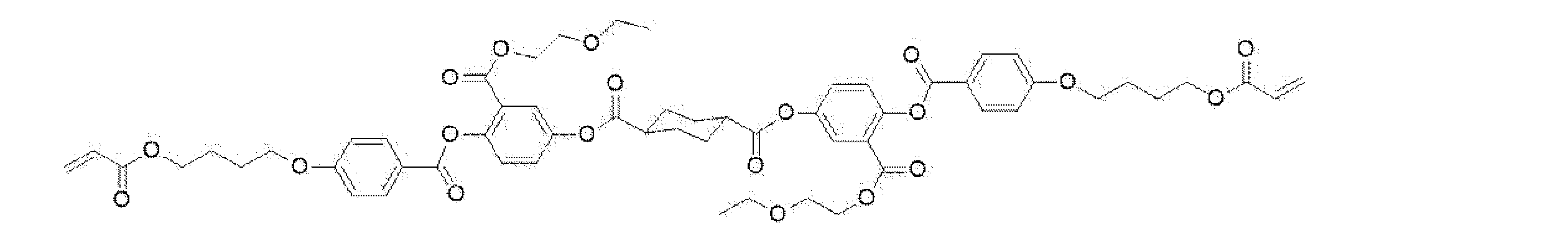
Rod-shaped liquid crystal compound 102:
棒状液晶化合物201及び202:

Rod-shaped liquid crystal compounds 201 and 202:
配向制御剤1:
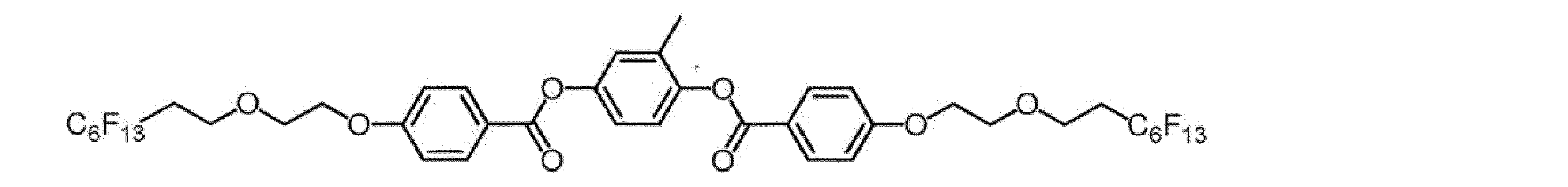
Orientation control agent 1:
配向制御剤3:

Orientation control agent 3:
(コレステリック液晶層の反射特性)
上記で調製した各コレステリック液晶層形成用塗布液を用いて、後述のコレステリック液晶層の作製と同様にして、仮支持体上に膜厚3μm程度の単一層の各コレステリック液晶層(重合反応により硬化した層)を作製した。作製した各コレステリック液晶層は全て右円偏光反射層であり、選択反射中心波長(中心波長)及び反射ピークの半値幅は、下記表1に示す波長であることを確認した。
なお、表1に記載の選択反射中心波長及び反射ピークの半値幅は、後述の[評価α]選択反射層の反射スペクトルの測定により測定した値である。 (Reflection characteristics of cholesteric liquid crystal layer)
Using each cholesteric liquid crystal layer-forming coating solution prepared above, each cholesteric liquid crystal layer of a single layer having a thickness of about 3 μm (cured by polymerization reaction) was formed on a temporary support in the same manner as in the preparation of the cholesteric liquid crystal layer described later. layer) was prepared. It was confirmed that all of the cholesteric liquid crystal layers prepared were right-handed circularly polarized light reflective layers, and that the selective reflection central wavelength (central wavelength) and the half width of the reflection peak were the wavelengths shown in Table 1 below.
The selective reflection central wavelength and the half width of the reflection peak shown in Table 1 are the values measured by measuring the reflection spectrum of the [Evaluation α] selective reflection layer described later.

(2)位相差層形成用塗布液
下記成分を下記に示す組成比となるように混合し、位相差層形成用塗布液を調製した。
・混合物1 100質量部
・フッ素系水平配向剤1(配向制御剤1) 0.05質量部
・フッ素系水平配向剤2(配向制御剤2) 0.01質量部
・重合開始剤IRGACURE OXE01(商品名、BASF社製)
1.0質量部
・溶媒(メチルエチルケトン) 溶質濃度が20質量%となる量 (2) Retardation Layer-Forming Coating Liquid A retardation layer-forming coating liquid was prepared by mixing the following components so as to have the composition ratio shown below.
・Mixture 1 100 parts by mass ・Fluorine-based horizontal alignment agent 1 (alignment control agent 1) 0.05 mass parts ・Fluorine-based horizontal alignment agent 2 (alignment control agent 2) 0.01 mass parts ・Polymerization initiator IRGACURE OXE01 (product name, manufactured by BASF)
1.0 parts by mass Solvent (methyl ethyl ketone) Amount that makes thesolute concentration 20% by mass
下記成分を下記に示す組成比となるように混合し、位相差層形成用塗布液を調製した。
・混合物1 100質量部
・フッ素系水平配向剤1(配向制御剤1) 0.05質量部
・フッ素系水平配向剤2(配向制御剤2) 0.01質量部
・重合開始剤IRGACURE OXE01(商品名、BASF社製)
1.0質量部
・溶媒(メチルエチルケトン) 溶質濃度が20質量%となる量 (2) Retardation Layer-Forming Coating Liquid A retardation layer-forming coating liquid was prepared by mixing the following components so as to have the composition ratio shown below.
・Mixture 1 100 parts by mass ・Fluorine-based horizontal alignment agent 1 (alignment control agent 1) 0.05 mass parts ・Fluorine-based horizontal alignment agent 2 (alignment control agent 2) 0.01 mass parts ・Polymerization initiator IRGACURE OXE01 (product name, manufactured by BASF)
1.0 parts by mass Solvent (methyl ethyl ketone) Amount that makes the
(3)偏光変換層形成用塗布液
下記成分を下記に示す組成比となるように混合し、偏光変換層形成用塗布液を調製した。
・混合物1 100質量部
・フッ素系水平配向剤1(配向制御剤1) 0.05質量部
・フッ素系水平配向剤2(配向制御剤2) 0.02質量部
・右旋回性キラル剤PaliocolorLC756(商品名、BASF社
製) 0.26質量部
・重合開始剤IRGACURE OXE01(商品名、BASF社製)
1.0質量部
・溶媒(メチルエチルケトン) 溶質濃度が20質量%となる量 (3) Coating Liquid for Forming a Polarization Conversion Layer The following components were mixed so as to have the composition ratio shown below to prepare a coating liquid for forming a polarization conversion layer.
・Mixture 1: 100 parts by mass ・Fluorine-based horizontal alignment agent 1 (alignment control agent 1): 0.05 mass parts ・Fluorine-based horizontal alignment agent 2 (alignment control agent 2): 0.02 mass parts ・Right-handed chiral agent Paliocolor LC756 (trade name, manufactured by BASF) 0.26 parts by mass Polymerization initiator IRGACURE OXE01 (trade name, manufactured by BASF)
1.0 parts by mass Solvent (methyl ethyl ketone) Amount that makes thesolute concentration 20% by mass
下記成分を下記に示す組成比となるように混合し、偏光変換層形成用塗布液を調製した。
・混合物1 100質量部
・フッ素系水平配向剤1(配向制御剤1) 0.05質量部
・フッ素系水平配向剤2(配向制御剤2) 0.02質量部
・右旋回性キラル剤PaliocolorLC756(商品名、BASF社
製) 0.26質量部
・重合開始剤IRGACURE OXE01(商品名、BASF社製)
1.0質量部
・溶媒(メチルエチルケトン) 溶質濃度が20質量%となる量 (3) Coating Liquid for Forming a Polarization Conversion Layer The following components were mixed so as to have the composition ratio shown below to prepare a coating liquid for forming a polarization conversion layer.
・Mixture 1: 100 parts by mass ・Fluorine-based horizontal alignment agent 1 (alignment control agent 1): 0.05 mass parts ・Fluorine-based horizontal alignment agent 2 (alignment control agent 2): 0.02 mass parts ・Right-handed chiral agent Paliocolor LC756 (trade name, manufactured by BASF) 0.26 parts by mass Polymerization initiator IRGACURE OXE01 (trade name, manufactured by BASF)
1.0 parts by mass Solvent (methyl ethyl ketone) Amount that makes the
混合物1:

Mixture 1:
配向制御剤2:
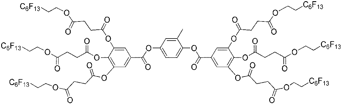
Orientation control agent 2:
(偏光変換層の偏光特性)
上記で調製した偏光変換層形成用塗布液から得られる偏光変換層の、光の入射角5°における選択反射中心波長λは10000nmであった。
この光の入射角5°における選択反射中心波長λは、上記で調製した偏光変換層形成用塗布液を用いて、仮支持体上に、膜厚3μm程度の単一層のコレステリック液晶層を作製して、FTIR(Fourier Transform Infrared Spectroscopy、パーキンエルマー社製、商品名:Spectrum Two)により測定した。
また、コレステリック液晶層において、螺旋構造の膜厚dは『螺旋構造のピッチP×ピッチ数』で表される。上述のように、螺旋構造のピッチPとは、螺旋配向された液晶化合物が360°回転する際の層の厚みを意味する。また、コレステリック液晶層では、光の入射角5°における選択反射中心波長λは『螺旋構造のピッチP×面内の平均屈折率n』と一致する(λ=P×n)。従って、螺旋構造のピッチPは『光の入射角5°における選択反射中心波長λ/面内の平均屈折率n』となる(P=λ/n)。 (Polarization properties of polarization conversion layer)
The selective reflection center wavelength λ of the polarization conversion layer obtained from the coating solution for forming the polarization conversion layer prepared above was 10000 nm at a light incident angle of 5°.
The selective reflection central wavelength λ at the incident angle of 5° of light was obtained by using the coating liquid for forming the polarization conversion layer prepared above to prepare a single-layer cholesteric liquid crystal layer having a thickness of about 3 μm on the temporary support. FTIR (Fourier Transform Infrared Spectroscopy, manufactured by PerkinElmer, trade name: Spectrum Two).
In addition, in the cholesteric liquid crystal layer, the film thickness d of the helical structure is represented by "the pitch P of the helical structure.times.the number of pitches". As described above, the pitch P of the helical structure means the thickness of the layer when the helically aligned liquid crystal compound rotates 360°. Further, in the cholesteric liquid crystal layer, the selective reflection center wavelength λ at a light incident angle of 5° coincides with “the pitch P of the helical structure×the in-plane average refractive index n” (λ=P×n). Therefore, the pitch P of the helical structure is "selective reflection central wavelength λ at an incident angle of 5°/in-plane average refractive index n" (P = λ/n).
[実施例1]ウィンドシールドガラスの作製
<1-1>コレステリック液晶層からなる選択反射層の作製
(1)鹸化処理したセルロースアシレートフィルムの作製
国際公開第2014/112575号の実施例20に記載のセルロースアシレートフィルムの作製において、コア層セルロースアシレートドープとして国際公開第2014/112575号の段落[0277]に記載の紫外線吸収剤2質量部に代えて、セルロールアセテート100質量部(エステルオリゴマーAを含まない)に対して帝盛化工社製の紫外線吸収剤UV-531(商品名)を3質量部配合したコア層セルロースアシレートドープを用いた以外は同様にして、厚さ40μmのセルロースアシレートフィルムを作製した。
作製したセルロースアシレートフィルムを、温度60℃の誘電式加熱ロールを通過させ、フィルム表面温度を40℃に昇温した。その後、フィルムの片面に下記に示す組成のアルカリ溶液を、バーコーターを用いて塗布量14mL/m2となるように塗布し、110℃に加熱したスチーム式遠赤外ヒーター(ノリタケカンパニーリミテド社製)の下に、10秒間滞留させた。
次いで、同じくバーコーターを用いて、純水を3mL/m2となるように塗布した。
次いで、ファウンテンコーターによる水洗とエアナイフによる水切りとを、3回繰り返した後に、70℃の乾燥ゾーンに5秒間滞留させて乾燥し、鹸化処理したセルロースアシレートフィルム(透明支持体)を作製した。
鹸化処理したセルロースアシレートフィルムの面内位相差をAxoScan(Axometrics社製、商品名)で測定したところ、1nmであった。 [Example 1] Preparation of windshield glass <1-1> Preparation of selective reflection layer composed of cholesteric liquid crystal layer (1) Preparation of saponified cellulose acylate film Described in Example 20 of WO 2014/112575 100 parts by mass of cellulose acetate (ester oligomer cellulose acylate dope with a thickness of 40 μm except that a core layer cellulose acylate dope containing 3 parts by mass of an ultraviolet absorber UV-531 (trade name) manufactured by Teisei Kako Co., Ltd. was used. An acylate film was produced.
The produced cellulose acylate film was passed through a dielectric heating roll at a temperature of 60°C to raise the film surface temperature to 40°C. After that, an alkaline solution having the composition shown below was applied to one side of the film using a bar coater so that the coating amount was 14 mL/m 2 , and heated to 110 ° C. with a steam type far-infrared heater (manufactured by Noritake Co., Ltd.). ) for 10 seconds.
Then, using the same bar coater, pure water was applied so as to be 3 mL/m 2 .
Subsequently, washing with water using a fountain coater and draining with an air knife were repeated three times, and then the film was dried by staying in a drying zone at 70°C for 5 seconds to prepare a saponified cellulose acylate film (transparent support).
The in-plane retardation of the saponified cellulose acylate film was measured with AxoScan (manufactured by Axometrics, trade name) and found to be 1 nm.
――――――――――――――――――――――――――――――――――
アルカリ溶液の組成
――――――――――――――――――――――――――――――――――
・水酸化カリウム 4.7質量部
・水 15.7質量部
・イソプロパノール 64.8質量部
・界面活性剤(C16H33O(CH2CH2O)10H) 1.0質量部
・プロピレングリコール 14.9質量部
―――――――――――――――――――――――――――――――――― ――――――――――――――――――――――――――――――――――
Composition of Alkaline Solution――――――――――――――――――――――――――――――――
・Potassium hydroxide 4.7 parts by mass ・Water 15.7 parts by mass ・Isopropanol 64.8 parts by mass ・Surfactant (C16H33O(CH2CH2O)10H ) 1.0 parts by mass ・Propylene Glycol 14.9 parts by mass――――――――――――――――――――――――――――――――――
(2)配向膜の形成
鹸化処理したセルロースアシレートフィルム(透明支持体)の鹸化処理面に、下記に示す組成の配向膜形成用塗布液を、ワイヤーバーコーターで24mL/m2となるように塗布し、100℃の温風で120秒乾燥し、配向膜を形成した。 (2) Formation of Orientation Film A coating solution for forming an orientation film having the composition shown below was applied to the saponified surface of the saponified cellulose acylate film (transparent support) with a wire bar coater so as to give a concentration of 24 mL/m 2 . It was applied and dried with hot air at 100° C. for 120 seconds to form an alignment film.
鹸化処理したセルロースアシレートフィルム(透明支持体)の鹸化処理面に、下記に示す組成の配向膜形成用塗布液を、ワイヤーバーコーターで24mL/m2となるように塗布し、100℃の温風で120秒乾燥し、配向膜を形成した。 (2) Formation of Orientation Film A coating solution for forming an orientation film having the composition shown below was applied to the saponified surface of the saponified cellulose acylate film (transparent support) with a wire bar coater so as to give a concentration of 24 mL/m 2 . It was applied and dried with hot air at 100° C. for 120 seconds to form an alignment film.
――――――――――――――――――――――――――――――――――
配向膜形成用塗布液の組成
――――――――――――――――――――――――――――――――――
・下記に示す変性ポリビニルアルコール 28質量部
・クエン酸エステル(商品名:AS3、三共化学社製) 1.2質量部
・光開始剤(商品名:イルガキュア2959、BASF社製)
0.84質量部
・グルタルアルデヒド 2.8質量部
・水 699質量部
・メタノール 226質量部
―――――――――――――――――――――――――――――――――― ――――――――――――――――――――――――――――――――――
Composition of coating solution for forming alignment film――――――――――――――――――――――――――――――――――
- Modified polyvinyl alcohol shown below 28 parts by mass - Citric acid ester (trade name: AS3, manufactured by Sankyo Chemical Co., Ltd.) 1.2 parts by mass - Photoinitiator (trade name: Irgacure 2959, manufactured by BASF)
0.84 parts by mass Glutaraldehyde 2.8 parts by mass Water 699 parts by mass Methanol 226 parts by mass ――――――――――――――――――――――――――― ―――――――
変性ポリビニルアルコール:

Modified polyvinyl alcohol:
(3)位相差層と選択反射層と偏光変換層との積層体の作製
(3-1)位相差層の作製
配向膜を形成したセルロースアシレートフィルムを、支持体(透明基材)として用いた。
支持体のうち配向膜の面に、支持体の長辺方向を基準に時計回りに45°回転させた方向にラビング処理を施した。具体的には、レーヨン布を用い、圧力:0.1kgf(0.98N)、回転数:1000rpm(revolutions per minute)、搬送速度:10m/min、回数:1往復の条件で行った。 (3) Preparation of Laminate of Retardation Layer, Selective Reflection Layer, and Polarization Conversion Layer (3-1) Preparation of Retardation Layer A cellulose acylate film having an orientation film formed thereon is used as a support (transparent substrate). board.
The orientation film surface of the support was rubbed in a direction rotated clockwise by 45° with respect to the long side direction of the support. Specifically, rayon cloth was used, pressure: 0.1 kgf (0.98 N), number of revolutions: 1000 rpm (revolutions per minute), conveying speed: 10 m/min, number of reciprocations: 1.
支持体上の配向膜のラビングした表面に、上記で調製した位相差層形成用塗布液をワイヤーバーを用いて塗布した後、乾燥させた。
次いで、50℃のホットプレート上に置き、酸素濃度1000ppm以下の環境で、フュージョンUVシステムズ社製の無電極ランプ「Dバルブ」(60mW/cm2)によって6秒間、紫外線を照射し、液晶相を固定した。これによりして、所望の正面位相差、すなわち、所望のレタデーションとなるように厚さを調整した位相差層を得た。
作製した位相差層のレタデーションをAxoScan(Axometrics社製、商品名)で測定したところ、126nmであった。 The retardation layer-forming coating solution prepared above was applied to the rubbed surface of the alignment film on the support using a wire bar, and then dried.
Next, it is placed on a hot plate at 50° C. and irradiated with ultraviolet rays for 6 seconds by an electrodeless lamp “D bulb” (60 mW/cm 2 ) manufactured by Fusion UV Systems in an environment with an oxygen concentration of 1000 ppm or less to convert the liquid crystal phase. Fixed. As a result, a retardation layer having a thickness adjusted so as to provide a desired frontal retardation, that is, a desired retardation, was obtained.
When the retardation of the produced retardation layer was measured by AxoScan (manufactured by Axometrics, trade name), it was 126 nm.
(3-2)選択反射層の作製
得られた位相差層の表面に、上記で調製したコレステリック液晶層(UV1)形成用塗布液を、乾燥後の膜の厚さが後記表3に記載の膜厚になるようにワイヤーバーを用いて室温にて塗布して塗布層を得た。
塗布層を室温で30秒間乾燥させた後、85℃の雰囲気で2分間加熱した。その後、酸素濃度1000ppm以下の環境で、60℃でフュージョン社製のDバルブ(60mW/cm2のランプ)によって、出力60%で6~12秒間、紫外線を照射し、コレステリック液晶相を固定して、後記表3に記載の膜厚のコレステリック液晶層UV1を得た。
次に、得られたコレステリック液晶層UV1の表面に、コレステリック液晶層B1、コレステリック液晶層G1、及び、コレステリック液晶層R1を、後記表3に記載の膜厚となるようにしてこの順に積層し、位相差層の上に4層のコレステリック液晶層が積層されてなる積層体を得た。
なお、各コレステリック液晶層B1、G1及びR1は、上記コレステリック液晶層UV1の作製において、コレステリック液晶層(UV1)形成用塗布液に代えて、対応する各コレステリック液晶層(B1、G1及びR1)形成用塗布液を用いた以外は同様にして、1層ずつ作製した。
なお、No.106の選択反射層の作製においては、コレステリック液晶層UV1を設けず、位相差層の表面にコレステリック液晶層B1が積層されるように変更した以外は同様にして作製した。 (3-2) Preparation of selective reflection layer On the surface of the obtained retardation layer, the coating liquid for forming the cholesteric liquid crystal layer (UV1) prepared above is applied, and the thickness of the film after drying is shown in Table 3 below. A coating layer was obtained by coating at room temperature using a wire bar so as to obtain a film thickness.
After drying the coating layer at room temperature for 30 seconds, it was heated in an atmosphere of 85° C. for 2 minutes. After that, in an environment with an oxygen concentration of 1000 ppm or less, ultraviolet light is irradiated at 60° C. for 6 to 12 seconds with a D bulb (60 mW/cm 2 lamp) manufactured by Fusion Co., Ltd. at an output of 60% to fix the cholesteric liquid crystal phase. , to obtain a cholesteric liquid crystal layer UV1 having a thickness shown in Table 3 below.
Next, on the surface of the obtained cholesteric liquid crystal layer UV1, a cholesteric liquid crystal layer B1, a cholesteric liquid crystal layer G1, and a cholesteric liquid crystal layer R1 are laminated in this order so as to have the film thicknesses shown in Table 3 below, A laminate was obtained in which four cholesteric liquid crystal layers were laminated on the retardation layer.
Incidentally, each of the cholesteric liquid crystal layers B1, G1 and R1 is used for forming the corresponding cholesteric liquid crystal layers (B1, G1 and R1) instead of the coating solution for forming the cholesteric liquid crystal layer (UV1) in the preparation of the cholesteric liquid crystal layer UV1. Each layer was prepared in the same manner, except that the coating solution for the above was used.
In addition, No. The selective reflection layer of No. 106 was prepared in the same manner, except that the cholesteric liquid crystal layer UV1 was not provided and the cholesteric liquid crystal layer B1 was laminated on the surface of the retardation layer.
(3―3)偏光変換層の作製
次に、得られた積層体のうちコレステリック液晶層の最表面に、上記で調製した偏光変換層形成用塗布液を、膜厚1.7μmとなるように塗布して、偏光変換層(ツイスト層)を形成した。なお、偏光変換層の形成は、上述したコレステリック液晶層の作製において、コレステリック液晶層形成用塗布液に代えて偏光変換層形成用塗布液を用いた以外は同様にして作製した。
得られた偏光変換層は、選択反射中心波長λ10000nm、ピッチ数0.265のツイスト層であった。
このようにして、支持体(透明基材)上に、位相差層、選択反射層及び偏光変換層がこの順に積層されてなる積層体(この積層体を「反射フィルム」とも称す。)を作製した。 (3-3) Preparation of Polarization Conversion Layer Next, the coating solution for forming the polarization conversion layer prepared above was applied to the outermost surface of the cholesteric liquid crystal layer in the obtained laminate so as to have a thickness of 1.7 μm. By coating, a polarization conversion layer (twisted layer) was formed. The polarization conversion layer was formed in the same manner as in the preparation of the cholesteric liquid crystal layer described above, except that the coating liquid for forming the polarization conversion layer was used instead of the coating liquid for forming the cholesteric liquid crystal layer.
The resulting polarization conversion layer was a twisted layer with a selective reflection center wavelength of λ10000 nm and a pitch number of 0.265.
Thus, a laminate (this laminate is also referred to as a "reflection film") is produced by laminating the retardation layer, the selective reflection layer and the polarization conversion layer in this order on the support (transparent substrate). bottom.
<1-2>直線偏光反射フィルムからなる選択反射層(誘電体多層膜)の作製
特表平9-506837号公報に記載された方法に基づき、以下のようにして、直線偏光反射フィルムからなる選択反射層を作製した。 <1-2> Production of selective reflection layer (dielectric multilayer film) made of linearly polarized light reflective film Based on the method described in Japanese Patent Application Laid-Open No. 9-506837, a linearly polarized light reflective film is made as follows. A selective reflection layer was produced.
特表平9-506837号公報に記載された方法に基づき、以下のようにして、直線偏光反射フィルムからなる選択反射層を作製した。 <1-2> Production of selective reflection layer (dielectric multilayer film) made of linearly polarized light reflective film Based on the method described in Japanese Patent Application Laid-Open No. 9-506837, a linearly polarized light reflective film is made as follows. A selective reflection layer was produced.
2,6-ポリエチレンナフタレート(PEN)、及び、ナフタレート70モル%とテレフタレート30モル%とのコポリエステル(coPEN)を、ジオールとしてエチレングリコールを用いて、標準ポリエステル樹脂合成釜においてそれぞれ合成した。
得られたPEN及びcoPENの単層フィルムを押出成型し、約150℃で、延伸比5:1で延伸し、約230℃で30秒間、熱処理した。この延伸熱処理の結果、PENフィルムの遅相軸(配向軸)に関する屈折率は約1.86、横断軸に関する屈折率は1.64となり、coPENフィルムは等方性であり、屈折率は約1.64となることを確認した。 2,6-polyethylene naphthalate (PEN) and a copolyester of 70 mol % naphthalate and 30 mol % terephthalate (coPEN) were each synthesized in a standard polyester resin synthesis reactor using ethylene glycol as the diol.
The resulting monolayer films of PEN and coPEN were extruded, stretched at a draw ratio of 5:1 at about 150°C, and heat treated at about 230°C for 30 seconds. As a result of this stretching heat treatment, the PEN film has a refractive index of about 1.86 with respect to the slow axis (orientation axis) and a refractive index of 1.64 with respect to the transverse axis. 0.64.
次に、延伸比を調整することにより、PENフィルムの遅相軸に関する屈折率は約1.71、横断軸に関する屈折率は1.64となり、coPENフィルムは等方性であり、屈折率は約1.64となることを確認した。すなわち、光学異方性層であるPENフィルムの遅相軸方向の屈折率と、光学等方性層であるcoPENフィルムの屈折率との差Δnは0.07である。
Then, by adjusting the draw ratio, the PEN film has a refractive index about 1.71 for the slow axis and a refractive index about 1.64 for the transverse axis, and the coPEN film is isotropic, with a refractive index of about It was confirmed to be 1.64. That is, the difference Δn between the refractive index in the slow axis direction of the PEN film, which is the optically anisotropic layer, and the refractive index of the coPEN film, which is the optically isotropic layer, is 0.07.
続いて、PENおよびcoPENを同時押し出しして得られる積層体を、延伸し、熱処理することにより、直線偏光反射フィルム(「反射フィルム」とも称す。)を作製した。この直線偏光反射フィルムの厚さは約28μmであり、下記表2のUV2の列に示す膜厚のPENとcoPENとを交互に44層ずつ有する直線偏光反射層UV2、下記表2の、B2の列に示す膜厚のPENとcoPENとを交互に44層ずつ有する直線偏光反射層B2、G2の列に示す膜厚のPENとcoPENとを交互に39層ずつ有する直線偏光反射層G2、及び、R2の列に示す膜厚のPENとcoPENとを交互に38層ずつ有する直線偏光反射層R2をこの順に有する。
具体的には、特表平9-506837号公報の実施例1に記載の条件と同様にして、標準押出ダイを装着した88スロット供給ブロックを用いて、下記表2のUV2層、B2層、G2層及びR2層に対応する延伸前の各積層体をそれぞれ作製した後、これらを全て積層した積層体について、約150℃において5:1の延伸比で1軸延伸を行い、延伸した積層体を、エアーオーブン内において、約230℃で30秒間、熱処理して、直線偏光反射フィルムを作製した。
例えば、下記表2のUV2層に対応する延伸前の積層体については、反射波長445nmの光学的4分の1波長厚さになる様に、押し出し成形は295℃の条件で、PENは約7.9ポンド/時間で、coPENは7.6ポンド/時間で押し出しした。その他のB2層、G2層及びR2層にそれぞれ対応する延伸前の積層体についても同様の考え方に基づき押し出し成形した。
なお、表2に記載の選択反射中心波長及び反射ピークの半値幅は、後述の[評価α]選択反射層の反射スペクトルの測定により測定した値である。 Subsequently, a laminate obtained by coextrusion of PEN and coPEN was stretched and heat-treated to prepare a linearly polarized light reflective film (also referred to as a “reflective film”). The thickness of this linearly polarized light reflective film is about 28 μm, and the linearly polarized light reflective layer UV2 having 44 layers of PEN and coPEN alternately having the film thickness shown in the UV2 column of Table 2 below, B2 of Table 2 below. A linearly polarized light reflecting layer B2 having 44 alternating layers of PEN and coPEN with the film thickness indicated in the column, a linearly polarized light reflecting layer G2 having 39 layers of alternating PEN and coPEN with the film thickness indicated in the column of G2, and It has a linearly polarized light reflecting layer R2 having 38 layers of PEN and coPEN alternately having the film thicknesses shown in the row R2, in this order.
Specifically, using an 88-slot feed block equipped with a standard extrusion die, UV2 layer, B2 layer, After preparing each laminate corresponding to the G2 layer and the R2 layer before stretching, the laminate obtained by laminating all of these is uniaxially stretched at about 150 ° C. at a draw ratio of 5: 1 to obtain a stretched laminate. was heat-treated in an air oven at about 230° C. for 30 seconds to prepare a linearly polarized light reflective film.
For example, for the unstretched laminate corresponding to the UV2 layer in Table 2 below, the extrusion was performed at 295° C. and the PEN was about 7 so as to have an optical quarter-wave thickness with a reflection wavelength of 445 nm. At 0.9 lbs/hr, coPEN extruded at 7.6 lbs/hr. The laminates before stretching corresponding to the other B2 layer, G2 layer and R2 layer were also extruded based on the same concept.
The selective reflection central wavelength and the half width of the reflection peak shown in Table 2 are values measured by measuring the reflection spectrum of the selective reflection layer in [Evaluation α] described later.
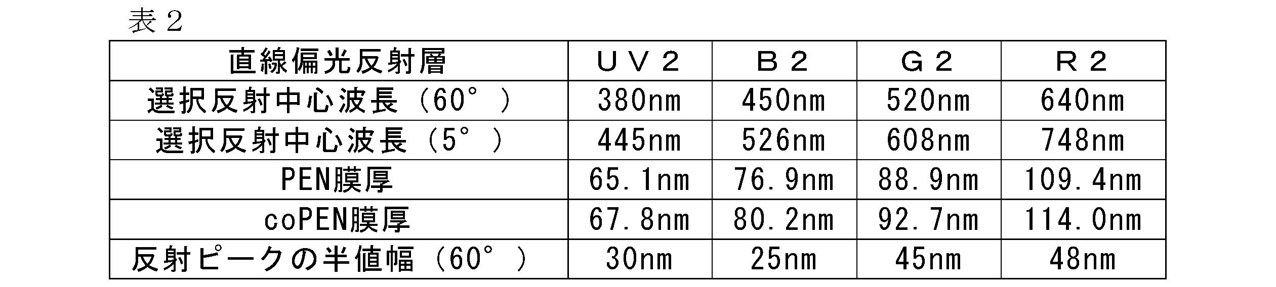
<2-1>コレステリック液晶層からなる選択反射層を有するウィンドシールドガラスの作製
上記で作製した、支持体(透明基材)、位相差層、選択反射層、及び、偏光変換層がこの順に積層されてなる積層体を用い、第2のガラス板、中間膜、偏光変換層、選択反射層(コレステリック液晶層)、位相差層、支持体(透明基材)、ヒートシール層、及び、第1のガラス板がこの順に積層されてなる積層体を作製した。
なお、上記の積層体におけるヒートシール層は、コレステリック液晶層からなる選択反射層の支持体(透明基材)側にヒートシール層形成用塗布液をワイヤーバーを用いて塗布後、乾燥させて50℃にて1分間加熱処理を行うことにより、厚み1μmのヒートシール層を形成した。
得られた積層体を90℃、10kPa(0.1気圧)下で一時間保持した後に、オートクレーブ(栗原製作所製)にて115℃、1.3MPa(13気圧)で20分間加熱して気泡を除去し、ウィンドシールドガラスNo.101~104、106及びc11を得た。 <2-1> Preparation of windshield glass having a selective reflection layer composed of a cholesteric liquid crystal layer The support (transparent base material), the retardation layer, the selective reflection layer, and the polarization conversion layer prepared above are laminated in this order. Using a laminate formed by A laminated body was prepared by laminating the glass plates in this order.
The heat-seal layer in the above laminate is obtained by applying a heat-seal layer-forming coating liquid to the support (transparent substrate) side of the selective reflection layer made of the cholesteric liquid crystal layer using a wire bar and then drying it for 50 minutes. A heat seal layer having a thickness of 1 µm was formed by heat-treating at °C for 1 minute.
After holding the obtained laminate at 90° C. and 10 kPa (0.1 atmosphere) for 1 hour, it was heated in an autoclave (manufactured by Kurihara Seisakusho) at 115° C. and 1.3 MPa (13 atmospheres) for 20 minutes to remove air bubbles. Remove the windshield glass No. 101-104, 106 and c11 were obtained.
<2-2>直線偏光反射フィルムからなる選択反射層を有するウィンドシールドガラスの作製
上記で作製した直線偏光反射フィルムを用い、第2のガラス板、中間膜、選択反射層(誘電体多層膜)、中間膜、及び、第1のガラス板がこの順に積層されてなる積層体を作製した。得られた積層体を90℃、10kPa(0.1気圧)下で一時間保持した後に、オートクレーブ(栗原製作所製)にて115℃、1.3MPa(13気圧)で20分間加熱して気泡を除去し、ウィンドシールドガラスNo.105を得た。
なお、直線偏光反射フィルムにおける直線偏光反射層UV2が第1のガラス板側となり、直線偏光反射層R2が第2のガラス板側になるようにして積層した。 <2-2> Preparation of windshield glass having a selective reflection layer made of a linearly polarized light reflecting film Using the linearly polarized light reflecting film prepared above, a second glass plate, an intermediate film, and a selective reflection layer (dielectric multilayer film) are formed. , an intermediate film, and a first glass plate were laminated in this order to prepare a laminate. After holding the obtained laminate at 90° C. and 10 kPa (0.1 atmosphere) for 1 hour, it was heated in an autoclave (manufactured by Kurihara Seisakusho) at 115° C. and 1.3 MPa (13 atmospheres) for 20 minutes to remove air bubbles. Remove the windshield glass No. 105 was obtained.
The linearly polarized light reflecting layer UV2 in the linearly polarized light reflecting film was placed on the first glass plate side, and the linearly polarized light reflecting layer R2 was placed on the second glass plate side.
上記ウィンドシールドガラスは、上記第1のガラス板及び第2のガラス板と同じ形状に、各層をカッティングして使用した。
上記ウィンドシールドガラスの作製に用いたガラス板、中間膜、ヒートシール層形成用塗布液は、それぞれ下記の通りである。
第1のガラス板及び第2のガラス板として、縦120mm×横100mm、厚さ2mmのガラス板(セントラル硝子社製、FL2、可視光線透過率90%)を使用した。
また、中間膜として、積水化学社製の厚さ0.38mmのPVB(ポリビニルブチラール)フィルムを使用した。
また、ヒートシール層の作製には、下記成分を下記に示す組成比となるように混合、調製した、ヒートシール層形成用塗布液を使用した。
(ヒートシール層形成用塗布液)
・PVBシート片(積水化学社製、エスレックフィルム) 5.0質量部
・メタノール 90.25質量部
・ブタノール 4.75質量部 The windshield glass was used by cutting each layer into the same shape as the first glass plate and the second glass plate.
The glass plate, the intermediate film, and the coating solution for forming the heat seal layer used for the production of the windshield glass are as follows.
As the first glass plate and the second glass plate, glass plates having a length of 120 mm, a width of 100 mm, and a thickness of 2 mm (FL2, visible light transmittance of 90%, manufactured by Central Glass Co., Ltd.) were used.
A 0.38 mm-thick PVB (polyvinyl butyral) film manufactured by Sekisui Chemical Co., Ltd. was used as an intermediate film.
Also, for the production of the heat seal layer, a heat seal layer-forming coating liquid prepared by mixing the following components so as to have the composition ratio shown below was used.
(Coating liquid for forming heat seal layer)
・PVB sheet piece (manufactured by Sekisui Chemical Co., Ltd., S-lec film) 5.0 parts by mass ・Methanol 90.25 parts by mass ・Butanol 4.75 parts by mass
下記表3に、各ウィンドシールドガラスにおける選択反射層に係る構成をまとめて示す。
なお、No.c11における選択反射層は、No.103の選択反射層の作製において、各コレステリック液晶層(UV1、B1、G1及びR1)形成用塗布液に代えて、特開2018-81296号公報の表2に記載の反射層の各塗布液(UV、B、G及びR)をそれぞれ用いた以外は同様にして作製した。
No.c11における各コレステリック液晶層(UV3、B3、G3及びR3)の光学特性は、特開2018-81296号公報の表3に記載の各反射層(UV、B、G及びR)の光学特性とそれぞれ同じである。
また、後述の[評価α]選択反射層の反射スペクトルの測定において、光の入射角を60°に設定して測定したNo.c11の選択反射層における各選択反射中心波長を有する反射ピークの半値幅は、コレステリック液晶層UV3が30nm、コレステリック液晶層B3が35nm、コレステリック液晶層G3が45nm、コレステリック液晶層R3が47nmであった。 Table 3 below summarizes the configuration of the selective reflection layer in each windshield glass.
In addition, No. The selective reflection layer in c11 is No. In the preparation of the selective reflection layer No. 103, instead of the coating liquid for forming each cholesteric liquid crystal layer (UV1, B1, G1 and R1), each coating liquid for the reflective layer described in Table 2 of JP-A-2018-81296 ( UV, B, G and R) were used in the same manner.
No. The optical properties of each cholesteric liquid crystal layer (UV3, B3, G3 and R3) in c11 are the same as the optical properties of each reflective layer (UV, B, G and R) described in Table 3 of JP-A-2018-81296. are the same.
In addition, in the measurement of the reflection spectrum of the [Evaluation α] selective reflection layer described later, No. 1 was measured by setting the incident angle of light to 60°. The half width of the reflection peak having each selective reflection center wavelength in the selective reflection layer c11 was 30 nm for the cholesteric liquid crystal layer UV3, 35 nm for the cholesteric liquid crystal layer B3, 45 nm for the cholesteric liquid crystal layer G3, and 47 nm for the cholesteric liquid crystal layer R3. .

[実施例2]ヘッドアップディスプレイの設計
上記で作製したウィンドシールドガラスNo.101~106及びc11と、投映像を形成するためのレーザー光源を含むプロジェクターとを備えたヘッドアップディスプレイNo.201~206及びc21を、各ウィンドシールドガラスにおける第2のガラス板側がレーザー光源の光が入射する側になるようにして設計した。
ヘッドアップディスプレイシステムNo.201~206が本発明のヘッドアップディスプレイシステムであり、ヘッドアップディスプレイシステムNo.c21が比較のヘッドアップディスプレイシステムである。
また、各ウィンドシールドガラスにおける選択反射層の反射特性と各レーザー光源の出力パワー、並びに、各ヘッドアップディスプレイシステムにおける選択反射層の反射率とレーザー光の輝度との関係、画像色味及び反射色味の評価結果について、後記表4にまとめて示す。 [Example 2] Design of head-up display Windshield glass No. 1 produced above. 101 to 106 and c11, and a projector including a laser light source for forming a projected image. 201 to 206 and c21 were designed so that the second glass plate side of each windshield glass was the side on which the light from the laser light source was incident.
Head-up display system No. 201 to 206 are head-up display systems of the present invention. c21 is a comparative head-up display system.
In addition, the reflection characteristics of the selective reflection layer in each windshield glass and the output power of each laser light source, the relationship between the reflectance of the selective reflection layer and the brightness of the laser light in each head-up display system, image color and reflected color Taste evaluation results are summarized in Table 4 below.
[評価α]選択反射層の反射スペクトルの測定
作製したウィンドシールドガラスのうち、第1のガラス板側の裏面に黒色PET(ポリエチレンテレフタレート)フィルム(光吸収体)を貼り合わせた。
分光光度計(日本分光株式会社製、V-670)を用いて、ウィンドシールドガラスの第2のガラス板から、ウィンドシールドガラス表面の法線方向に対し所望の角度の方向からP偏光又はS偏光をそれぞれ入射し、波長300~800nmの帯域におけるP偏光及びS偏光の反射スペクトルをそれぞれ測定した。測定したP偏光の反射スペクトルとS偏光の反射スペクトルの平均値(平均の反射スペクトル)を求めた。図6に示すグラフは、ウィンドシールドガラスNo.101の表面の法線方向に対し5°の角度で光入射して測定した反射スペクトルであり、図7に示すグラフは、ウィンドシールドガラスNo.101の表面の法線方向に対し60°の角度で光入射して測定した反射スペクトルである。
本発明において、選択反射中心波長(60°)、反射率(60°)及び半値幅(60°)については、ウィンドシールドガラス表面の法線方向に対し60°の角度で光入射して測定した反射スペクトルに基づき算出した値を意味し、選択反射中心波長(5°)については、ウィンドシールドガラス表面の法線方向に対し5°の角度で光入射して測定した反射スペクトルに基づき算出した値を意味する。 [Evaluation α] Measurement of Reflection Spectrum of Selective Reflection Layer A black PET (polyethylene terephthalate) film (light absorber) was attached to the rear surface of the first glass plate of the prepared windshield glass.
Using a spectrophotometer (manufactured by JASCO Corporation, V-670), from the second glass plate of the windshield glass, from the direction of the desired angle with respect to the normal direction of the windshield glass surface P-polarized light or S-polarized light were incident, and the reflection spectra of P-polarized light and S-polarized light in the wavelength band of 300 to 800 nm were measured. An average value (average reflection spectrum) of the measured P-polarized reflection spectrum and S-polarized reflection spectrum was obtained. The graph shown in FIG. 101. The graph shown in FIG. It is a reflection spectrum measured by light incident at an angle of 60° with respect to the normal direction of the surface of 101 .
In the present invention, the selective reflection center wavelength (60°), reflectance (60°) and half width (60°) were measured by light incident at an angle of 60° with respect to the normal direction of the windshield glass surface. Refers to the value calculated based on the reflection spectrum, and for the selective reflection center wavelength (5°), the value calculated based on the reflection spectrum measured by light incident at an angle of 5° to the normal direction of the windshield glass surface. means
なお、P偏光を入射した際の反射率とS偏光を入射した際の反射率との平均値は、無偏光(自然光)を入射した際の反射率と同義である。すなわち、P偏光の反射スペクトルとS偏光の反射スペクトルの平均値は、自然光を入射した際の反射スペクトルと同義である。
The average value of the reflectance when P-polarized light is incident and the reflectance when S-polarized light is incident is synonymous with the reflectance when unpolarized light (natural light) is incident. That is, the average value of the P-polarized reflection spectrum and the S-polarized reflection spectrum is synonymous with the reflection spectrum when natural light is incident.
算出したP偏光とS偏光の反射スペクトルの平均値から、波長400nm以上500nm未満の帯域、波長500nm以上600nm未満の帯域及び波長600nm~700nmの帯域における各選択反射中心波長λとその半値幅Δλを、前述の方法により、自然光反射率の最大値、自然光反射率の最大の極大値と最小の極小値との中間の反射率となる2つの波長に基づき、それぞれ算出した。また、各選択反射中心波長λにおける反射率は、算出したP偏光とS偏光の反射スペクトルの平均値において、選択反射中心波長λにおける反射率の値をとした。
From the calculated average values of the reflection spectra of P-polarized light and S-polarized light, each selective reflection center wavelength λ and its half width Δλ in the wavelength band of 400 nm or more and less than 500 nm, the wavelength band of 500 nm or more and less than 600 nm, and the wavelength band of 600 nm to 700 nm , were calculated by the method described above, based on the two wavelengths at which the maximum value of the natural light reflectance and the reflectance between the maximum maximum value and the minimum minimum value of the natural light reflectance were obtained. Further, the reflectance at each selective reflection center wavelength λ was the reflectance value at the selective reflection center wavelength λ in the calculated average value of the reflection spectra of P-polarized light and S-polarized light.
[評価1]反射色味の評価
第1のガラス板側から第1のガラス板の法線方向に対し5°の方向から自然光を入射し、第1のガラス板の法線方向(図5における観察位置5番の位置)から分光光度計(日本分光株式会社製、V-670)を用いて反射率スペクトルを測定した。JIS(日本産業規格) R3106に従って、380~780nmでの10nm毎の波長において、反射率に視感度に応じた係数およびD65光源の発光スペクトルをそれぞれ乗じて反射率を計算し、そのスペクトルから反射色味のa*及びb*を算出した。
また、自然光の入射角度を第1のガラス板の法線方向に対し60°の方向に変更した場合についても同様に算出した。
反射色味は、下記評価基準に当てはめ評価した。本試験においては、評価「AA~B」であれば、反射色味が充分に抑えられており、好ましい。なお、下記表4において、反射色味の5°及び60°の欄に記載の評価は、それぞれ、第1のガラス板の法線方向に対し5°又は60°の方向から自然光を入射した場合の評価に相当する。
- 評価基準(反射色味) -
AA:|a*|≦3、かつ、|b*|≦3であり、白色を映した際に白く見える。
A:|a*|≦5、かつ、|b*|≦5(ただし、上記AAに該当するものを除く)であり、白色を映した際にほぼ白く見える。
B:|a*|≦7、かつ、|b*|≦7(ただし、上記のAA又はAに該当するものを除く)であり、白色を映した際にごくわずかに色味がかって見える。 [Evaluation 1] Evaluation of reflected color tone Natural light is incident from the first glass plate side in a direction of 5° with respect to the normal direction of the first glass plate, and the normal direction of the first glass plate ( A reflectance spectrum was measured using a spectrophotometer (manufactured by JASCO Corporation, V-670) from the observation position No. 5). According to JIS (Japanese Industrial Standard) R3106, at wavelengths of 380 to 780 nm in increments of 10 nm, the reflectance is multiplied by a coefficient corresponding to the luminous efficiency and the emission spectrum of the D65 light source to calculate the reflectance, and the reflected color is calculated from the spectrum. Taste a* and b* were calculated.
Similar calculations were also made when the incident angle of natural light was changed to 60° with respect to the normal direction of the first glass plate.
Reflected color was evaluated by applying the following evaluation criteria. In this test, the evaluation "AA to B" is preferable because the reflected color is sufficiently suppressed. In Table 4 below, the evaluations described in the 5° and 60° columns of the reflected color are when natural light is incident from a direction of 5° or 60° with respect to the normal direction of the first glass plate, respectively. equivalent to the evaluation of
- Evaluation criteria (reflected color) -
AA: |a*|≤3 and |b*|≤3, and looks white when white is projected.
A: |a*|≤5 and |b*|≤5 (excluding those corresponding to AA above), and when white is projected, it looks almost white.
B: |a*|≤7 and |b*|≤7 (excluding those corresponding to AA or A above), and when white is projected, it looks very slightly tinted.
[評価2]画像色味の評価
プロジェクターのレーザー光源の各色の出力パワーを下記表4に記載の値となるように調整を行い、第2のガラス板の法線方向に対し60°の方向から、プロジェクターから白色画像を投映した。その画像の色味を、トプコン社製の色彩輝度計BM-5A(商品名)を用いて測定し、下記評価基準に当てはめ評価した。
より詳細には、図5に示す配置で画像色味の評価を行った。作製したウィンドシールドガラス1を、長辺を横に短辺を縦にして、第2のガラス板側が下方になるように傾斜させて、この第2のガラス板側に配置したプロジェクター2から第2のガラス板に画像を投映し、その投映画像について、色彩輝度計3を用いて色味を測定した。
プロジェクター2としては、青色光、緑色光及び赤色光のレーザ光源を有するRGB光源モジュールとMEMSミラーとからなるプロジェクターを用いた。プロジェクター2とウィンドシールドガラス1との距離は500mmとした。評価はp偏光、すなわち、図5でその電気ベクトル振動面が紙面に平行である直線偏光を用いた。
本試験においては、評価「AA~B」が合格レベルである。
- 評価基準(画像色味) -
AA:|a*|≦3、かつ、|b*|≦3であり、画像が白く見える。
A:|a*|≦5、かつ、|b*|≦5(ただし、上記AAに該当するものを除く)であり、画像がほぼ白く見える。
B:|a*|≦7、かつ、|b*|≦7(ただし、上記のAA又はAに該当するものを除く)であり、画像がわずかに色味がかって見える。
C:|a*|≦9、かつ、|b*|≦9(ただし、上記のAA、A及びBのいずれかに該当するものを除く)であり、画像が色味がかって見える。 [Evaluation 2] Evaluation of image color The output power of each color of the laser light source of the projector was adjusted to the values shown in Table 4 below, and from a direction of 60° with respect to the normal direction of the second glass plate , projected a white image from the projector. The color tone of the image was measured using a color luminance meter BM-5A (trade name) manufactured by Topcon Corporation, and evaluated according to the following evaluation criteria.
More specifically, the image color was evaluated with the arrangement shown in FIG. The manufactured windshield glass 1 is tilted so that the long side is horizontal and the short side is vertical, and the second glass plate side faces downward. An image was projected onto the glass plate of No. 2, and the color tone of the projected image was measured using a color luminance meter 3 .
As the projector 2, a projector composed of an RGB light source module having laser light sources of blue, green, and red light and a MEMS mirror was used. The distance between the projector 2 and the windshield glass 1 was set to 500 mm. For evaluation, p-polarized light, that is, linearly polarized light whose electric vector vibration plane is parallel to the plane of the paper in FIG. 5 was used.
In this test, the evaluation "AA to B" is the passing level.
- Evaluation criteria (image color) -
AA: |a*|≤3 and |b*|≤3, and the image looks white.
A: |a*|≤5 and |b*|≤5 (excluding those corresponding to AA above), and the image looks almost white.
B: |a*|≤7 and |b*|≤7 (excluding those corresponding to AA or A above), and the image appears slightly tinted.
C: |a*|≤9 and |b*|≤9 (excluding those corresponding to any of the above AA, A, and B), and the image appears tinted.
[評価β]レーザー光の輝度の測定
上記[評価2]画像色味の評価のレーザー光源の出力パワーの条件における、各色レーザー光の輝度LB、LG及びLRについては、下記のようにして測定した。
LBは、青色レーザー光源の出力パワーを49mWに設定した際のプロジェクター2の輝度を、トプコン社製の色彩輝度計BM-5A(商品名)を用いて測定した。LG及びLRについても同様に、表4に記載の緑色及び赤色レーザー光源の出力パワーの条件における輝度を、トプコン社製の色彩輝度計BM-5A(商品名)を用いて測定した。
このようにして測定したプロジェクター2から出射される光におけるレーザー光の輝度LB、LG及びLRと、選択反射層の反射率RB、RG及びRRとの積から、XB、XG及びXRを算出し、これらの比であるXB/XG、XB/XR、XG/XRを算出した。 [Evaluation β] Measurement of brightness of laser light The luminances LB , LG , and LR of each color laser light under the conditions of the output power of the laser light source in the above [Evaluation 2] Image color evaluation were performed as follows. measured by
For LB , the luminance of the projector 2 when the output power of the blue laser light source was set to 49 mW was measured using a color luminance meter BM-5A (trade name) manufactured by Topcon Corporation. Similarly, for LG and LR , the luminance under the conditions of the output power of the green and red laser light sources shown in Table 4 was measured using a color luminance meter BM-5A (trade name) manufactured by Topcon Corporation.
X B , _ _ _ _ XG and XR were calculated, and their ratios XB / XG , XB / XR and XG / XR were calculated.
[評価3]可視光線透過率の評価
第1のガラス板側から第1のガラス板の法線方向に対し0°の方向から自然光を入射し、第2のガラス板側の法線方向から分光光度計(日本分光株式会社製、V-670)を用いて透過率スペクトルを測定した。JIS R3106に従って、380~780nmでの10nm毎の波長において、透過率に視感度に応じた係数およびA光源の発光スペクトルをそれぞれ乗じて透過率を計算した。
本発明のヘッドアップディスプレイシステムNo.201~206におけるウィンドシールドガラスNo.101~106はいずれも、透過率が80%以上であり、これは、第1のガラス板及び第2のガラス板に代えてグリーンガラスで合わせガラスを形成した場合でも、透過率が70%を十分超えるレベルであった。 [Evaluation 3] Evaluation of visible light transmittance Natural light is incident from the direction of 0° to the normal direction of the first glass plate from the side of the first glass plate, and the light is dispersed from the normal direction of the second glass plate side. A transmittance spectrum was measured using a photometer (manufactured by JASCO Corporation, V-670). According to JIS R3106, the transmittance was calculated by multiplying the transmittance by a coefficient corresponding to the luminosity factor and the emission spectrum of the A light source at wavelengths of 380 to 780 nm in increments of 10 nm.
Head-up display system No. of the present invention. Windshield glass Nos. 201-206. All of 101 to 106 have a transmittance of 80% or more, which means that the transmittance of 70% is achieved even when the laminated glass is formed of green glass instead of the first glass plate and the second glass plate. It was well above the level.

(表の注)
選択反射波長(60°)とは選択反射中心波長(60°)を意味し、単位はnmであり、反射率(60°)の単位は%であり、レーザー光源のパワーの単位はmWである。
PB、PG及びPRは、順に、青色レーザー光の出力パワー、緑色レーザー光の出力パワー、及び、赤色レーザー光の出力パワーを意味する。
RB/RGは反射率の比を示し、「/」の右側の値に対する「/」の左側の値の比を示す。
表中のXB/XGが規定(a)におけるXB/XGに、表中のXB/XRが規定(b)におけるXB/XRに、表中のXG/XRが規定(c)におけるXG/XRに、それぞれ相当する。 (Note to table)
The selective reflection wavelength (60°) means the selective reflection center wavelength (60°), the unit is nm, the unit of reflectance (60°) is %, and the unit of the power of the laser light source is mW. .
PB, PG and PR mean the output power of blue laser light, the output power of green laser light, and the output power of red laser light, respectively.
RB/RG indicates the reflectance ratio, and indicates the ratio of the value on the left side of "/" to the value on the right side of "/".
XB/XG in the table corresponds to XB / XG in specification (a), XB/XR in the table corresponds to XB /XR in specification (b), and XG/ XR in the table corresponds to specification (c). They correspond to X G /X R , respectively.
表4の結果から、以下のことがわかる。
ウィンドシールドガラスにおける選択反射層と、投映像を形成するためのレーザー光源とが規定(a)~(c)を満たさない比較のヘッドアップディスプレイシステムNo.c21では、投映される画像が色味がかって見え(画像色味の評価「C」)、劣っていた。
これに対して、規定(a)~(c)を満たす本発明のヘッドアップディスプレイシステムNo.201~206は、投映される画像はほとんど色味がかっておらずニュートラルに近い色味であり(画像色味の評価「A」~「B」)、優れた画像色味を示していた。
また、本発明のヘッドアップディスプレイシステムNo.201~206は、外観からの反射色味自体も、比較のヘッドアップディスプレイシステムNo.c21と同レベル以上の高い透明性を示していた。 The results in Table 4 show the following.
Comparative head-up display system No. where the selective reflection layer in the windshield glass and the laser light source for forming the projected image do not satisfy the provisions (a) to (c). In c21, the projected image looked tinted (evaluation of image tint "C") and was inferior.
On the other hand, head-up display system No. 1 of the present invention that satisfies the provisions (a) to (c). In 201 to 206, the projected image had almost no tint and had a near neutral tint (evaluation of image tint "A" to "B"), indicating excellent image tint.
Also, head-up display system No. 1 of the present invention. 201 to 206 are the comparative head-up display system Nos. 201 to 206. It showed high transparency equal to or higher than that of c21.
本発明をその実施態様とともに説明したが、我々は特に指定しない限り我々の発明を説明のどの細部においても限定しようとするものではなく、添付の請求の範囲に示した発明の精神と範囲に反することなく幅広く解釈されるべきであると考える。
While we have described our invention in conjunction with embodiments thereof, we do not intend to limit our invention in any detail to the description unless specified otherwise, which is contrary to the spirit and scope of the invention as set forth in the appended claims. I think it should be interpreted broadly.
本願は、2021年9月30日に日本国で特許出願された特願2021-162101に基づく優先権を主張するものであり、これはここに参照してその内容を本明細書の記載の一部として取り込む。
This application claims priority based on Japanese Patent Application No. 2021-162101 filed in Japan on September 30, 2021, the contents of which are incorporated herein by reference. taken in as a part.
1 ウィンドシールドガラス
2 プロジェクター
3 色彩輝度計
5 観察位置
10 反射フィルム
10A 直線偏光反射フィルム
10B 直線偏光反射フィルム
11 選択反射層
12 コレステリック液晶層
12R 光の入射角60°における選択反射中心波長λRを有するコレステリック液晶層
12G 光の入射角60°における選択反射中心波長λGを有するコレステリック液晶層
12B 光の入射角60°における選択反射中心波長λBを有するコレステリック液晶層
13R 光の入射角60°における選択反射中心波長λRを有する第1積層部
13G 光の入射角60°における選択反射中心波長λGを有する第2積層部
13B 光の入射角60°における選択反射中心波長λBを有する第3積層部
13Ra、13Ga、13Ba 光学異方性層
13Rb、13Gb、13Bb 光学等方性層
14 偏光変換層
16 位相差層
18 透明基材
20 ヘッドアップディスプレイシステム(HUDシステム)
22 プロジェクター
24、24A、24B ウィンドシールドガラス
28 第2のガラス板
30 第1のガラス板
36 中間膜
38 接着剤層(ヒートシール層)
D 運転者
ne1 光学異方性層の遅相軸方向の屈折率
no1 光学異方性層の遅相軸と直交する方向の屈折率
no2 光学等方性層の屈折率
Y 上下方向 1 windshield glass 2 projector 3color luminance meter 5 observation position 10 reflective film 10A linearly polarized reflective film 10B linearly polarized reflective film 11 selective reflection layer 12 cholesteric liquid crystal layer 12R has a selective reflection central wavelength λ R at a light incident angle of 60 ° Cholesteric liquid crystal layer 12G Cholesteric liquid crystal layer 12B having a selective reflection central wavelength λ G at a light incidence angle of 60° Cholesteric liquid crystal layer 12B having a selective reflection central wavelength λ B at a light incidence angle of 60° 13R Selection at a light incidence angle of 60° A first lamination part 13G having a reflection central wavelength λ R A second lamination part 13B having a selective reflection central wavelength λ G at a light incidence angle of 60° A third lamination part 13B having a selective reflection central wavelength λ B at a light incidence angle of 60° Part 13Ra, 13Ga, 13Ba Optically anisotropic layer 13Rb, 13Gb, 13Bb Optically isotropic layer 14 Polarization conversion layer 16 Retardation layer 18 Transparent substrate 20 Head-up display system (HUD system)
22 projectors 24, 24A, 24B windshield glass 28 second glass plate 30 first glass plate 36 intermediate film 38 adhesive layer (heat seal layer)
D Driver n e1 Refractive index in the direction of the slow axis of the optically anisotropic layer n o1 Refractive index in the direction perpendicular to the slow axis of the optically anisotropic layer n o2 Refractive index of the optically isotropic layer Y Vertical direction
2 プロジェクター
3 色彩輝度計
5 観察位置
10 反射フィルム
10A 直線偏光反射フィルム
10B 直線偏光反射フィルム
11 選択反射層
12 コレステリック液晶層
12R 光の入射角60°における選択反射中心波長λRを有するコレステリック液晶層
12G 光の入射角60°における選択反射中心波長λGを有するコレステリック液晶層
12B 光の入射角60°における選択反射中心波長λBを有するコレステリック液晶層
13R 光の入射角60°における選択反射中心波長λRを有する第1積層部
13G 光の入射角60°における選択反射中心波長λGを有する第2積層部
13B 光の入射角60°における選択反射中心波長λBを有する第3積層部
13Ra、13Ga、13Ba 光学異方性層
13Rb、13Gb、13Bb 光学等方性層
14 偏光変換層
16 位相差層
18 透明基材
20 ヘッドアップディスプレイシステム(HUDシステム)
22 プロジェクター
24、24A、24B ウィンドシールドガラス
28 第2のガラス板
30 第1のガラス板
36 中間膜
38 接着剤層(ヒートシール層)
D 運転者
ne1 光学異方性層の遅相軸方向の屈折率
no1 光学異方性層の遅相軸と直交する方向の屈折率
no2 光学等方性層の屈折率
Y 上下方向 1 windshield glass 2 projector 3
22
D Driver n e1 Refractive index in the direction of the slow axis of the optically anisotropic layer n o1 Refractive index in the direction perpendicular to the slow axis of the optically anisotropic layer n o2 Refractive index of the optically isotropic layer Y Vertical direction
Claims (9)
- 選択反射層を有するウィンドシールドガラスと、該ウィンドシールドガラスに投映像を形成するためのレーザー光源を含むプロジェクターとを有するヘッドアップディスプレイシステムであって、
前記選択反射層が、光の入射角60°における選択反射中心波長として下記のλB、λG及びλRの3つの波長を含み、
400nm≦λB<500nm
500nm≦λG<600nm
600nm≦λR≦700nm
前記レーザー光源が、青色光、緑色光及び赤色光の3色のレーザー光を発し、
下記の規定(a)~(c)の全てを満たす、ヘッドアップディスプレイシステム。
規定(a) 0.80≦XB/XG≦1.20
規定(b) 0.80≦XB/XR≦1.20
規定(c) 0.80≦XG/XR≦1.20
上記規定において、XB=RB×LBであり、XG=RG×LGであり、XR=RR×LRである。
RBは前記選択反射層のλBにおける自然光反射率を示し、RGは前記選択反射層のλGにおける自然光反射率を示し、RRは前記選択反射層のλRにおける自然光反射率を示す。また、LBは前記プロジェクターから出射される光における青色レーザー光の輝度を示し、LGは前記プロジェクターから出射される光における緑色レーザー光の輝度を示し、LRは前記プロジェクターから出射される光における赤色レーザー光の輝度を示す。 A head-up display system comprising a windshield glass having a selective reflection layer and a projector including a laser light source for forming a projected image on the windshield glass,
The selective reflection layer includes the following three wavelengths of λ B , λ G and λ R as selective reflection center wavelengths at an incident angle of light of 60°,
400 nm≦λ B <500 nm
500nm≦ λG <600nm
600nm≤λR≤700nm
The laser light source emits laser light of three colors of blue light, green light and red light,
A head-up display system that satisfies all of the following provisions (a) to (c).
Rule (a) 0.80≦X B /X G ≦1.20
Rule (b) 0.80≦X B /X R ≦1.20
Rule (c) 0.80≤XG / XR≤1.20
In the above definition, XB = RB x LB , XG = RG x LG , and XR = RR x LR .
RB indicates the natural light reflectance of the selective reflection layer at λB , RG indicates the natural light reflectance of the selective reflection layer at λG , and RR indicates the natural light reflectance of the selective reflection layer at λR . . Further, LB indicates the luminance of blue laser light in the light emitted from the projector, LG indicates the luminance of green laser light in the light emitted from the projector, and LR indicates the light emitted from the projector. shows the brightness of red laser light at . - 下記の規定(a1)~(c1)の全てを満たす、請求項1に記載のヘッドアップディスプレイシステム。
規定(a1) 0.90≦XB/XG≦1.10
規定(b1) 0.90≦XB/XR≦1.10
規定(c1) 0.90≦XG/XR≦1.10
上記規定において、XB、XG及びXRは、前記のXB、XG及びXRと同義である。 2. A head-up display system according to claim 1, which satisfies all of the following provisions (a1) to (c1).
Regulation (a1) 0.90≦X B /X G ≦1.10
Rule (b1) 0.90≦X B /X R ≦1.10
Regulation (c1) 0.90≦X G /X R ≦1.10
In the above definition, X B , X G and XR are synonymous with the above X B , X G and XR . - 前記選択反射層の前記の自然光反射率RB、RG及びRRが、RB>RG≧RRの関係を満たす、請求項1又は2に記載のヘッドアップディスプレイシステム。 The head-up display system according to claim 1 or 2, wherein the natural light reflectances RB , RG and RR of the selective reflection layer satisfy the relationship RB > RG ≥ RR .
- 前記選択反射層の前記の自然光反射率RB及びRGが、RB/RG≧1.10の関係を満たす、請求項1~3のいずれか1項に記載のヘッドアップディスプレイシステム。 The head-up display system according to any one of claims 1 to 3, wherein the natural light reflectances R B and R G of the selective reflection layer satisfy the relationship R B /R G ≧1.10.
- 前記選択反射層が含む、前記の光の入射角60°における選択反射中心波長λB、λG及びλRの半値幅がいずれも100nm以下であって、前記の自然光反射率RB、RG及びRRがいずれも25%以上である、請求項1~4のいずれか1項に記載のヘッドアップディスプレイシステム。 The selective reflection layer includes the selective reflection center wavelengths λ B , λ G and λ R at an incident angle of 60°, each of which has a half width of 100 nm or less, and the natural light reflectances RB and RG and RR are both 25% or more.
- 前記ウィンドシールドガラスが少なくとも1つの偏光変換層を含む、請求項1~5のいずれか1項に記載のヘッドアップディスプレイシステム。 The head-up display system according to any one of claims 1 to 5, wherein the windshield glass includes at least one polarization conversion layer.
- 前記選択反射層がコレステリック液晶からなる、請求項1~6のいずれか1項に記載のヘッドアップディスプレイシステム。 The head-up display system according to any one of claims 1 to 6, wherein the selective reflection layer is made of cholesteric liquid crystal.
- 前記選択反射層が、光学異方性層と光学等方性層とを積層してなる、請求項1~5のいずれか1項に記載のヘッドアップディスプレイシステム。 The head-up display system according to any one of claims 1 to 5, wherein the selective reflection layer is formed by laminating an optically anisotropic layer and an optically isotropic layer.
- 請求項1~8のいずれか1項に記載のヘッドアップディスプレイシステムを備えた輸送機。 A transport aircraft equipped with the head-up display system according to any one of claims 1 to 8.
Applications Claiming Priority (2)
| Application Number | Priority Date | Filing Date | Title |
|---|---|---|---|
| JP2021162101 | 2021-09-30 | ||
| JP2021-162101 | 2021-09-30 |
Publications (1)
| Publication Number | Publication Date |
|---|---|
| WO2023054324A1 true WO2023054324A1 (en) | 2023-04-06 |
Family
ID=85782715
Family Applications (1)
| Application Number | Title | Priority Date | Filing Date |
|---|---|---|---|
| PCT/JP2022/035856 WO2023054324A1 (en) | 2021-09-30 | 2022-09-27 | Head-up display system and transport |
Country Status (1)
| Country | Link |
|---|---|
| WO (1) | WO2023054324A1 (en) |
Citations (86)
| Publication number | Priority date | Publication date | Assignee | Title |
|---|---|---|---|---|
| US2367670A (en) | 1941-12-31 | 1945-01-23 | Du Pont | Cementing process |
| US2367661A (en) | 1941-12-31 | 1945-01-23 | Du Pont | Process of photopolymerization |
| US2448828A (en) | 1946-09-04 | 1948-09-07 | Du Pont | Photopolymerization |
| US2722512A (en) | 1952-10-23 | 1955-11-01 | Du Pont | Photopolymerization process |
| US2951758A (en) | 1957-05-17 | 1960-09-06 | Du Pont | Photopolymerizable compositions and elements |
| US3046127A (en) | 1957-10-07 | 1962-07-24 | Du Pont | Photopolymerizable compositions, elements and processes |
| US3549367A (en) | 1968-05-24 | 1970-12-22 | Du Pont | Photopolymerizable compositions containing triarylimidazolyl dimers and p-aminophenyl ketones |
| US4212970A (en) | 1977-11-28 | 1980-07-15 | Fuji Photo Film Co., Ltd. | 2-Halomethyl-5-vinyl-1,3,4-oxadiazole compounds |
| US4239850A (en) | 1977-11-29 | 1980-12-16 | Fuji Photo Film Co., Ltd. | Photopolymerizable composition |
| JPS60105667A (en) | 1983-10-12 | 1985-06-11 | ヘキスト・アクチエンゲゼルシヤフト | Photosensitive compound containing trichloromethyl group, manufacture and photosensitive mixture |
| US4683327A (en) | 1985-06-24 | 1987-07-28 | Celanese Corporation | Anisotropic heat-curable acrylic terminated monomers |
| JPS6340799B2 (en) | 1978-07-14 | 1988-08-12 | Basf Ag | |
| JPH01272551A (en) | 1988-04-22 | 1989-10-31 | Dainippon Printing Co Ltd | Polymerizable bifunctional acrylate monomer |
| JPH02141720A (en) | 1988-11-23 | 1990-05-31 | Nippon Denso Co Ltd | Head-up display device |
| US5013134A (en) | 1989-09-28 | 1991-05-07 | Hughes Aircraft Company | Ghost-free automotive head-up display employing a wedged windshield |
| JPH0529234B2 (en) | 1984-11-27 | 1993-04-28 | Esupe Fuaburiiku Fuarumatsuoiteitsusheru Pureparaate Gmbh Unto Co Kg | |
| JPH0616616A (en) | 1992-07-03 | 1994-01-25 | Canon Inc | Reactive liquid crystal compound, polymeric liquid crystal compound, liquid crystal composition and liquid crystal element |
| JPH07110469A (en) | 1993-08-16 | 1995-04-25 | Dainippon Ink & Chem Inc | Liquid crystal display element and its production |
| WO1995022586A1 (en) | 1994-02-19 | 1995-08-24 | Basf Aktiengesellschaft | New polymerisable liquid crystal compounds |
| WO1995024455A1 (en) | 1994-03-11 | 1995-09-14 | Basf Aktiengesellschaft | Novel polymerizable liquid-crystalline compounds |
| JPH07270711A (en) | 1994-03-30 | 1995-10-20 | Canon Inc | Information display device |
| WO1997000600A2 (en) | 1995-09-01 | 1997-01-09 | Basf Aktiengesellschaft | Polymerizable liquid-crystalline compounds |
| US5622648A (en) | 1993-10-15 | 1997-04-22 | Merck Patent Gesellschaft Mit Beschrankter Haftung | Reactive liquid crystal compounds |
| JPH09506837A (en) | 1993-12-21 | 1997-07-08 | ミネソタ・マイニング・アンド・マニュファクチュアリング・カンパニー | Multilayer optical film |
| JPH1029997A (en) | 1996-03-04 | 1998-02-03 | Ciba Specialty Chem Holding Inc | Alkylphenylbisacylphosphine oxide and photopolymerization initiator mixture |
| JPH1096874A (en) | 1996-05-24 | 1998-04-14 | Asahi Glass Co Ltd | Windshield glass for automobile and head-up display device |
| JPH1095788A (en) | 1996-08-28 | 1998-04-14 | Ciba Specialty Chem Holding Inc | Molecular complex compound as photoinitiator |
| WO1998023580A1 (en) | 1996-11-27 | 1998-06-04 | Basf Aktiengesellschaft | Polymerizable oligomesogenes |
| US5770107A (en) | 1995-10-05 | 1998-06-23 | Merck Patent Gesellschaft Mit Beschrankter Haftung | Reactive liquid crystalline compound |
| WO1998052905A1 (en) | 1997-05-22 | 1998-11-26 | Rolic Ag | New polymerisable liquid crystalline compounds |
| JPH1180081A (en) | 1997-09-05 | 1999-03-23 | Dainippon Ink & Chem Inc | Liquid crystal (meth)acrylate compound, its composition and optical isomer using the same |
| JP2000066385A (en) | 1998-08-18 | 2000-03-03 | Ciba Specialty Chem Holding Inc | SULFONYL OXIMES FOR HIGH SENSITIVITY THICK i-LINE PHOTORESIST |
| JP2000080068A (en) | 1998-06-26 | 2000-03-21 | Ciba Specialty Chem Holding Inc | New o-acyloxime photopolymerization initiator |
| JP2000221449A (en) | 1999-01-29 | 2000-08-11 | Arisawa Mfg Co Ltd | Video device |
| JP2001233842A (en) | 1999-12-15 | 2001-08-28 | Ciba Specialty Chem Holding Inc | Photoinitiator of oxime ester |
| JP2001328973A (en) | 2000-03-13 | 2001-11-27 | Fuji Photo Film Co Ltd | Polymerizable liquid crystal compound and optically antisotropic element |
| JP2002080478A (en) | 2000-06-27 | 2002-03-19 | Fuji Photo Film Co Ltd | Photoreactive optically active compound, photoreactive chiral agent, liquid crystal composition, liquid crystal color filter, optical film, recording medium, and method for changing twist structure of liquid crystal |
| JP2002080851A (en) | 2000-06-27 | 2002-03-22 | Fuji Photo Film Co Ltd | Photoreactive chiral agent, liquid crystal composition, liquid crystal color filter, optical film, recording medium, and method for changing twist structure of liquid crystal |
| JP2002179669A (en) | 2000-12-14 | 2002-06-26 | Fuji Photo Film Co Ltd | Optically active compound, photo-reactive chiral agent, liquid crystal composition, method for changing twist structure of liquid crystal, method for fixing spiral structure of liquid crystal, liquid crystal color filter, optical film and recording medium |
| JP2002179682A (en) | 2000-12-15 | 2002-06-26 | Fuji Photo Film Co Ltd | Optically active compound, photoreactive chiral agent, liquid crystal composition, liquid crystal color filter, optical film and recording medium, method for changing helical structure of liquid crystal and method for fixing helical structure of liquid crystal |
| JP2002179670A (en) | 2000-12-14 | 2002-06-26 | Fuji Photo Film Co Ltd | Optically active compound, photo-reactive chiral agent, liquid crystal composition, method for changing spiral structure of liquid crystal, method for fixing spiral structure of liquid crystal, liquid crystal color filter, optical film and recording medium |
| JP2002179681A (en) | 2000-12-15 | 2002-06-26 | Fuji Photo Film Co Ltd | Optically active compound, photoreactive chiral agent, liquid crystal composition, liquid crystal color filter, optical film and recording medium, method for changing helical structure of liquid crystal and method for fixing helical structure of liquid crystal |
| JP2002179668A (en) | 2000-12-15 | 2002-06-26 | Fuji Photo Film Co Ltd | Optically active compound, liquid crystal chiral agent, liquid crystal composition, liquid crystal color filter, optical film and recording medium |
| JP2002302487A (en) | 2000-12-14 | 2002-10-18 | Fuji Photo Film Co Ltd | Optically active compound, photoreaction type chiral agent, liquid crystal composition, method for changing spiral structure of liquid crystal, method for fixing spiral structure of liquid crystal, liquid crystal color filter, optical filter and recording medium |
| JP2002338668A (en) | 2001-05-15 | 2002-11-27 | Fuji Photo Film Co Ltd | Optically active polyester, photoreactive chiral agent, liquid crystal composition, liquid crystal color filter, optical film and recording medium, method of changing helical structure of liquid crystal, and method of fixing helical structure of liquid crystal |
| JP2002338575A (en) | 2001-05-16 | 2002-11-27 | Fuji Photo Film Co Ltd | Optically active isosorbide derivative and method for producing the same, photoreactive type chiral agent, liquid crystalline composition, liquid crystalline color filter, optical film and recording medium, method for changing helical structure of liquid crystal and method for fixing helical structure of liquid crystal |
| JP2003098470A (en) | 2001-09-21 | 2003-04-03 | Asahi Glass Co Ltd | Headup display device |
| JP2003287623A (en) | 2002-01-23 | 2003-10-10 | Nitto Denko Corp | Optical film, method for manufacturing the same, and optical retardation film and polarizing plate using the same |
| JP2003313292A (en) | 2002-04-19 | 2003-11-06 | Fuji Photo Film Co Ltd | Optically active polyester/amide, photoreactive chiral agent, liquid crystal composition, liquid crystal color filter, optical film and recording medium, and process for modifying and fixing helical structure of liquid crystal |
| JP2003313189A (en) | 2002-04-22 | 2003-11-06 | Fuji Photo Film Co Ltd | Optically active isosorbide derivative and method for producing the same, photoreactive chiral agent, liquid crystal composition, liquid crystal color filter, optical film and recording medium, method for changing spiral structure of liquid crystal and method for fixing spiral structure of liquid crystal |
| JP2006512622A (en) | 2002-12-31 | 2006-04-13 | スリーエム イノベイティブ プロパティズ カンパニー | Head-up display with polarized light source and wide-angle p-polarized reflective polarizer |
| JP2006342166A (en) | 2001-06-11 | 2006-12-21 | Ciba Specialty Chem Holding Inc | Photoinitiator of oxime ester having combined structure |
| JP2007523369A (en) | 2004-02-04 | 2007-08-16 | マイクロビジョン,インク. | Scanning beam head-up display apparatus and related systems and methods |
| JP2007272185A (en) | 2006-03-10 | 2007-10-18 | Fujifilm Corp | Composition, retardation plate, liquid crystal display device, average tilt angle regulator, and method for regulating average tilt angle |
| JP4223071B2 (en) | 2006-12-27 | 2009-02-12 | 株式会社Adeka | Oxime ester compound and photopolymerization initiator containing the compound |
| JP2010070543A (en) | 2008-08-18 | 2010-04-02 | Asahi Glass Co Ltd | Bifunctional polymerizable compound, liquid crystal composition, optical anisotropic material and optical element |
| JP2010145745A (en) | 2008-12-18 | 2010-07-01 | Equos Research Co Ltd | Image forming apparatus and head-up display device |
| JP2010181852A (en) | 2008-07-14 | 2010-08-19 | Fujifilm Corp | Optical anisotropic film, process for producing optical anisotropic film, substrate for liquid crystal cell, and liquid crystal display device |
| WO2010116912A1 (en) | 2009-04-08 | 2010-10-14 | 国立大学法人東京大学 | Tracking device, tracking microscope provided with the tracking device, and tracking method |
| JP2010262028A (en) | 2009-04-30 | 2010-11-18 | Nippon Steel Chem Co Ltd | Photosensitive resin composition for black matrix |
| JP4725516B2 (en) | 2004-06-25 | 2011-07-13 | 旭硝子株式会社 | Polymerizable liquid crystal compound, liquid crystal composition, and optically anisotropic material |
| US20120019923A1 (en) * | 2010-07-26 | 2012-01-26 | Microvision, Inc. | Variable Reflectivity Notch Filter and Optical Devices Using Same |
| JP2012203237A (en) | 2011-03-25 | 2012-10-22 | Fujifilm Corp | Method for manufacturing light-reflecting film |
| JP2012208494A (en) | 2011-03-17 | 2012-10-25 | Fujifilm Corp | Colored radiation-sensitive composition, colored cured film, color filter and manufacturing method of color filter, solid state image sensor, liquid crystal display device, and manufacturing method of dye |
| JP2012226303A (en) | 2011-12-21 | 2012-11-15 | Pioneer Electronic Corp | Light source unit and headup display |
| JP2013112631A (en) | 2011-11-28 | 2013-06-10 | Dic Corp | Polymerizable liquid crystal compound |
| JP2013113913A (en) | 2011-11-25 | 2013-06-10 | Fujifilm Corp | Film, and method for producing the same |
| JP2013114249A (en) | 2011-12-01 | 2013-06-10 | Toppan Printing Co Ltd | Black photosensitive resin composition and color filter |
| JP2013200474A (en) * | 2012-03-26 | 2013-10-03 | Jvc Kenwood Corp | Image display device and control method for image display device |
| JP2013228674A (en) | 2012-03-28 | 2013-11-07 | Nippon Seiki Co Ltd | Display device for vehicle |
| JP2014500852A (en) | 2010-10-05 | 2014-01-16 | ビーエーエスエフ ソシエタス・ヨーロピア | Oxime ester derivatives of benzocarbazole compounds and their use as photoinitiators in photopolymerizable compositions |
| JP2014034581A (en) | 2012-08-07 | 2014-02-24 | Fujifilm Corp | Liquid crystal composition, polymer, film, and cholesteric liquid crystal |
| WO2014112575A1 (en) | 2013-01-18 | 2014-07-24 | 富士フイルム株式会社 | Optical film, polarizing plate, and image display device |
| JP2014137466A (en) | 2013-01-16 | 2014-07-28 | Jsr Corp | Radiation-sensitive coloring composition, colored cured film and display element |
| WO2015115390A1 (en) | 2014-01-28 | 2015-08-06 | 富士フイルム株式会社 | Polymerizable compound, polymerizable composition, film and half mirror for displaying projected image |
| WO2015147243A1 (en) | 2014-03-28 | 2015-10-01 | 富士フイルム株式会社 | Polymerizable compound, polymer, polymerizable composition, film, and half mirror for projection image display |
| WO2015190157A1 (en) | 2014-06-13 | 2015-12-17 | 三菱電機株式会社 | Virtual image display device |
| WO2016035873A1 (en) | 2014-09-05 | 2016-03-10 | 富士フイルム株式会社 | Polymerizable compound, polymer, polymerizable composition, and film |
| WO2016047648A1 (en) | 2014-09-25 | 2016-03-31 | 富士フイルム株式会社 | Polymerizable composition comprising polymerizable compounds, film, and half mirror for projected-image display |
| JP2016053149A (en) | 2014-03-28 | 2016-04-14 | 富士フイルム株式会社 | Polymerizable compound, polymer, polymerizable composition, film, and half mirror for projection image display |
| JP2017021302A (en) | 2015-07-15 | 2017-01-26 | 日本精機株式会社 | Head-up display |
| JP2018081296A (en) | 2016-11-04 | 2018-05-24 | 富士フイルム株式会社 | Windshield glass, head-up display system, and half mirror film |
| JP2019059904A (en) * | 2017-09-28 | 2019-04-18 | マクセルホールディングス株式会社 | Optical film for glass laminate and glass laminate using the same |
| WO2019146423A1 (en) * | 2018-01-25 | 2019-08-01 | 富士フイルム株式会社 | Projected image display member, windshield glass, and head-up display system |
| WO2021153763A1 (en) * | 2020-01-30 | 2021-08-05 | 日本化薬株式会社 | Optical functional film for head-up display, optical laminate, functional glass, and head-up display system |
| JP2021162101A (en) | 2020-03-31 | 2021-10-11 | ダイハツ工業株式会社 | Power transmission mechanism |
-
2022
- 2022-09-27 WO PCT/JP2022/035856 patent/WO2023054324A1/en active Application Filing
Patent Citations (88)
| Publication number | Priority date | Publication date | Assignee | Title |
|---|---|---|---|---|
| US2367670A (en) | 1941-12-31 | 1945-01-23 | Du Pont | Cementing process |
| US2367661A (en) | 1941-12-31 | 1945-01-23 | Du Pont | Process of photopolymerization |
| US2448828A (en) | 1946-09-04 | 1948-09-07 | Du Pont | Photopolymerization |
| US2722512A (en) | 1952-10-23 | 1955-11-01 | Du Pont | Photopolymerization process |
| US2951758A (en) | 1957-05-17 | 1960-09-06 | Du Pont | Photopolymerizable compositions and elements |
| US3046127A (en) | 1957-10-07 | 1962-07-24 | Du Pont | Photopolymerizable compositions, elements and processes |
| US3549367A (en) | 1968-05-24 | 1970-12-22 | Du Pont | Photopolymerizable compositions containing triarylimidazolyl dimers and p-aminophenyl ketones |
| US4212970A (en) | 1977-11-28 | 1980-07-15 | Fuji Photo Film Co., Ltd. | 2-Halomethyl-5-vinyl-1,3,4-oxadiazole compounds |
| US4239850A (en) | 1977-11-29 | 1980-12-16 | Fuji Photo Film Co., Ltd. | Photopolymerizable composition |
| JPS6340799B2 (en) | 1978-07-14 | 1988-08-12 | Basf Ag | |
| JPS60105667A (en) | 1983-10-12 | 1985-06-11 | ヘキスト・アクチエンゲゼルシヤフト | Photosensitive compound containing trichloromethyl group, manufacture and photosensitive mixture |
| JPH0529234B2 (en) | 1984-11-27 | 1993-04-28 | Esupe Fuaburiiku Fuarumatsuoiteitsusheru Pureparaate Gmbh Unto Co Kg | |
| US4683327A (en) | 1985-06-24 | 1987-07-28 | Celanese Corporation | Anisotropic heat-curable acrylic terminated monomers |
| JPH01272551A (en) | 1988-04-22 | 1989-10-31 | Dainippon Printing Co Ltd | Polymerizable bifunctional acrylate monomer |
| JPH02141720A (en) | 1988-11-23 | 1990-05-31 | Nippon Denso Co Ltd | Head-up display device |
| US5013134A (en) | 1989-09-28 | 1991-05-07 | Hughes Aircraft Company | Ghost-free automotive head-up display employing a wedged windshield |
| JPH0616616A (en) | 1992-07-03 | 1994-01-25 | Canon Inc | Reactive liquid crystal compound, polymeric liquid crystal compound, liquid crystal composition and liquid crystal element |
| JPH07110469A (en) | 1993-08-16 | 1995-04-25 | Dainippon Ink & Chem Inc | Liquid crystal display element and its production |
| US5622648A (en) | 1993-10-15 | 1997-04-22 | Merck Patent Gesellschaft Mit Beschrankter Haftung | Reactive liquid crystal compounds |
| JPH09506837A (en) | 1993-12-21 | 1997-07-08 | ミネソタ・マイニング・アンド・マニュファクチュアリング・カンパニー | Multilayer optical film |
| WO1995022586A1 (en) | 1994-02-19 | 1995-08-24 | Basf Aktiengesellschaft | New polymerisable liquid crystal compounds |
| WO1995024455A1 (en) | 1994-03-11 | 1995-09-14 | Basf Aktiengesellschaft | Novel polymerizable liquid-crystalline compounds |
| JPH07270711A (en) | 1994-03-30 | 1995-10-20 | Canon Inc | Information display device |
| WO1997000600A2 (en) | 1995-09-01 | 1997-01-09 | Basf Aktiengesellschaft | Polymerizable liquid-crystalline compounds |
| US5770107A (en) | 1995-10-05 | 1998-06-23 | Merck Patent Gesellschaft Mit Beschrankter Haftung | Reactive liquid crystalline compound |
| JPH1029997A (en) | 1996-03-04 | 1998-02-03 | Ciba Specialty Chem Holding Inc | Alkylphenylbisacylphosphine oxide and photopolymerization initiator mixture |
| JPH1096874A (en) | 1996-05-24 | 1998-04-14 | Asahi Glass Co Ltd | Windshield glass for automobile and head-up display device |
| JPH1095788A (en) | 1996-08-28 | 1998-04-14 | Ciba Specialty Chem Holding Inc | Molecular complex compound as photoinitiator |
| WO1998023580A1 (en) | 1996-11-27 | 1998-06-04 | Basf Aktiengesellschaft | Polymerizable oligomesogenes |
| WO1998052905A1 (en) | 1997-05-22 | 1998-11-26 | Rolic Ag | New polymerisable liquid crystalline compounds |
| JPH1180081A (en) | 1997-09-05 | 1999-03-23 | Dainippon Ink & Chem Inc | Liquid crystal (meth)acrylate compound, its composition and optical isomer using the same |
| JP4454067B2 (en) | 1998-06-26 | 2010-04-21 | チバ ホールディング インコーポレーテッド | Novel O-acyloxime photoinitiator |
| JP2000080068A (en) | 1998-06-26 | 2000-03-21 | Ciba Specialty Chem Holding Inc | New o-acyloxime photopolymerization initiator |
| JP2000066385A (en) | 1998-08-18 | 2000-03-03 | Ciba Specialty Chem Holding Inc | SULFONYL OXIMES FOR HIGH SENSITIVITY THICK i-LINE PHOTORESIST |
| JP2000221449A (en) | 1999-01-29 | 2000-08-11 | Arisawa Mfg Co Ltd | Video device |
| JP2001233842A (en) | 1999-12-15 | 2001-08-28 | Ciba Specialty Chem Holding Inc | Photoinitiator of oxime ester |
| JP2001328973A (en) | 2000-03-13 | 2001-11-27 | Fuji Photo Film Co Ltd | Polymerizable liquid crystal compound and optically antisotropic element |
| JP2002080478A (en) | 2000-06-27 | 2002-03-19 | Fuji Photo Film Co Ltd | Photoreactive optically active compound, photoreactive chiral agent, liquid crystal composition, liquid crystal color filter, optical film, recording medium, and method for changing twist structure of liquid crystal |
| JP2002080851A (en) | 2000-06-27 | 2002-03-22 | Fuji Photo Film Co Ltd | Photoreactive chiral agent, liquid crystal composition, liquid crystal color filter, optical film, recording medium, and method for changing twist structure of liquid crystal |
| JP2002179669A (en) | 2000-12-14 | 2002-06-26 | Fuji Photo Film Co Ltd | Optically active compound, photo-reactive chiral agent, liquid crystal composition, method for changing twist structure of liquid crystal, method for fixing spiral structure of liquid crystal, liquid crystal color filter, optical film and recording medium |
| JP2002179670A (en) | 2000-12-14 | 2002-06-26 | Fuji Photo Film Co Ltd | Optically active compound, photo-reactive chiral agent, liquid crystal composition, method for changing spiral structure of liquid crystal, method for fixing spiral structure of liquid crystal, liquid crystal color filter, optical film and recording medium |
| JP2002302487A (en) | 2000-12-14 | 2002-10-18 | Fuji Photo Film Co Ltd | Optically active compound, photoreaction type chiral agent, liquid crystal composition, method for changing spiral structure of liquid crystal, method for fixing spiral structure of liquid crystal, liquid crystal color filter, optical filter and recording medium |
| JP2002179682A (en) | 2000-12-15 | 2002-06-26 | Fuji Photo Film Co Ltd | Optically active compound, photoreactive chiral agent, liquid crystal composition, liquid crystal color filter, optical film and recording medium, method for changing helical structure of liquid crystal and method for fixing helical structure of liquid crystal |
| JP2002179681A (en) | 2000-12-15 | 2002-06-26 | Fuji Photo Film Co Ltd | Optically active compound, photoreactive chiral agent, liquid crystal composition, liquid crystal color filter, optical film and recording medium, method for changing helical structure of liquid crystal and method for fixing helical structure of liquid crystal |
| JP2002179668A (en) | 2000-12-15 | 2002-06-26 | Fuji Photo Film Co Ltd | Optically active compound, liquid crystal chiral agent, liquid crystal composition, liquid crystal color filter, optical film and recording medium |
| JP2002338668A (en) | 2001-05-15 | 2002-11-27 | Fuji Photo Film Co Ltd | Optically active polyester, photoreactive chiral agent, liquid crystal composition, liquid crystal color filter, optical film and recording medium, method of changing helical structure of liquid crystal, and method of fixing helical structure of liquid crystal |
| JP2002338575A (en) | 2001-05-16 | 2002-11-27 | Fuji Photo Film Co Ltd | Optically active isosorbide derivative and method for producing the same, photoreactive type chiral agent, liquid crystalline composition, liquid crystalline color filter, optical film and recording medium, method for changing helical structure of liquid crystal and method for fixing helical structure of liquid crystal |
| JP2006342166A (en) | 2001-06-11 | 2006-12-21 | Ciba Specialty Chem Holding Inc | Photoinitiator of oxime ester having combined structure |
| JP2003098470A (en) | 2001-09-21 | 2003-04-03 | Asahi Glass Co Ltd | Headup display device |
| JP2003287623A (en) | 2002-01-23 | 2003-10-10 | Nitto Denko Corp | Optical film, method for manufacturing the same, and optical retardation film and polarizing plate using the same |
| JP2003313292A (en) | 2002-04-19 | 2003-11-06 | Fuji Photo Film Co Ltd | Optically active polyester/amide, photoreactive chiral agent, liquid crystal composition, liquid crystal color filter, optical film and recording medium, and process for modifying and fixing helical structure of liquid crystal |
| JP2003313189A (en) | 2002-04-22 | 2003-11-06 | Fuji Photo Film Co Ltd | Optically active isosorbide derivative and method for producing the same, photoreactive chiral agent, liquid crystal composition, liquid crystal color filter, optical film and recording medium, method for changing spiral structure of liquid crystal and method for fixing spiral structure of liquid crystal |
| JP2006512622A (en) | 2002-12-31 | 2006-04-13 | スリーエム イノベイティブ プロパティズ カンパニー | Head-up display with polarized light source and wide-angle p-polarized reflective polarizer |
| JP2007523369A (en) | 2004-02-04 | 2007-08-16 | マイクロビジョン,インク. | Scanning beam head-up display apparatus and related systems and methods |
| JP4725516B2 (en) | 2004-06-25 | 2011-07-13 | 旭硝子株式会社 | Polymerizable liquid crystal compound, liquid crystal composition, and optically anisotropic material |
| JP2007272185A (en) | 2006-03-10 | 2007-10-18 | Fujifilm Corp | Composition, retardation plate, liquid crystal display device, average tilt angle regulator, and method for regulating average tilt angle |
| JP4223071B2 (en) | 2006-12-27 | 2009-02-12 | 株式会社Adeka | Oxime ester compound and photopolymerization initiator containing the compound |
| JP2010181852A (en) | 2008-07-14 | 2010-08-19 | Fujifilm Corp | Optical anisotropic film, process for producing optical anisotropic film, substrate for liquid crystal cell, and liquid crystal display device |
| JP2010070543A (en) | 2008-08-18 | 2010-04-02 | Asahi Glass Co Ltd | Bifunctional polymerizable compound, liquid crystal composition, optical anisotropic material and optical element |
| JP2010145745A (en) | 2008-12-18 | 2010-07-01 | Equos Research Co Ltd | Image forming apparatus and head-up display device |
| WO2010116912A1 (en) | 2009-04-08 | 2010-10-14 | 国立大学法人東京大学 | Tracking device, tracking microscope provided with the tracking device, and tracking method |
| JP2010262028A (en) | 2009-04-30 | 2010-11-18 | Nippon Steel Chem Co Ltd | Photosensitive resin composition for black matrix |
| US20120019923A1 (en) * | 2010-07-26 | 2012-01-26 | Microvision, Inc. | Variable Reflectivity Notch Filter and Optical Devices Using Same |
| JP2014500852A (en) | 2010-10-05 | 2014-01-16 | ビーエーエスエフ ソシエタス・ヨーロピア | Oxime ester derivatives of benzocarbazole compounds and their use as photoinitiators in photopolymerizable compositions |
| JP2012208494A (en) | 2011-03-17 | 2012-10-25 | Fujifilm Corp | Colored radiation-sensitive composition, colored cured film, color filter and manufacturing method of color filter, solid state image sensor, liquid crystal display device, and manufacturing method of dye |
| JP2012203237A (en) | 2011-03-25 | 2012-10-22 | Fujifilm Corp | Method for manufacturing light-reflecting film |
| JP2013113913A (en) | 2011-11-25 | 2013-06-10 | Fujifilm Corp | Film, and method for producing the same |
| JP2013112631A (en) | 2011-11-28 | 2013-06-10 | Dic Corp | Polymerizable liquid crystal compound |
| JP2013114249A (en) | 2011-12-01 | 2013-06-10 | Toppan Printing Co Ltd | Black photosensitive resin composition and color filter |
| JP2012226303A (en) | 2011-12-21 | 2012-11-15 | Pioneer Electronic Corp | Light source unit and headup display |
| JP2013200474A (en) * | 2012-03-26 | 2013-10-03 | Jvc Kenwood Corp | Image display device and control method for image display device |
| JP2013228674A (en) | 2012-03-28 | 2013-11-07 | Nippon Seiki Co Ltd | Display device for vehicle |
| JP2014034581A (en) | 2012-08-07 | 2014-02-24 | Fujifilm Corp | Liquid crystal composition, polymer, film, and cholesteric liquid crystal |
| JP2014137466A (en) | 2013-01-16 | 2014-07-28 | Jsr Corp | Radiation-sensitive coloring composition, colored cured film and display element |
| WO2014112575A1 (en) | 2013-01-18 | 2014-07-24 | 富士フイルム株式会社 | Optical film, polarizing plate, and image display device |
| WO2015115390A1 (en) | 2014-01-28 | 2015-08-06 | 富士フイルム株式会社 | Polymerizable compound, polymerizable composition, film and half mirror for displaying projected image |
| JP2015163596A (en) | 2014-01-28 | 2015-09-10 | 富士フイルム株式会社 | Polymerizable compound, polymer, polymerizable composition, film, and half mirror for displaying projected image |
| JP2016053149A (en) | 2014-03-28 | 2016-04-14 | 富士フイルム株式会社 | Polymerizable compound, polymer, polymerizable composition, film, and half mirror for projection image display |
| WO2015147243A1 (en) | 2014-03-28 | 2015-10-01 | 富士フイルム株式会社 | Polymerizable compound, polymer, polymerizable composition, film, and half mirror for projection image display |
| WO2015190157A1 (en) | 2014-06-13 | 2015-12-17 | 三菱電機株式会社 | Virtual image display device |
| WO2016035873A1 (en) | 2014-09-05 | 2016-03-10 | 富士フイルム株式会社 | Polymerizable compound, polymer, polymerizable composition, and film |
| WO2016047648A1 (en) | 2014-09-25 | 2016-03-31 | 富士フイルム株式会社 | Polymerizable composition comprising polymerizable compounds, film, and half mirror for projected-image display |
| JP2017021302A (en) | 2015-07-15 | 2017-01-26 | 日本精機株式会社 | Head-up display |
| JP2018081296A (en) | 2016-11-04 | 2018-05-24 | 富士フイルム株式会社 | Windshield glass, head-up display system, and half mirror film |
| JP2019059904A (en) * | 2017-09-28 | 2019-04-18 | マクセルホールディングス株式会社 | Optical film for glass laminate and glass laminate using the same |
| WO2019146423A1 (en) * | 2018-01-25 | 2019-08-01 | 富士フイルム株式会社 | Projected image display member, windshield glass, and head-up display system |
| WO2021153763A1 (en) * | 2020-01-30 | 2021-08-05 | 日本化薬株式会社 | Optical functional film for head-up display, optical laminate, functional glass, and head-up display system |
| JP2021162101A (en) | 2020-03-31 | 2021-10-11 | ダイハツ工業株式会社 | Power transmission mechanism |
Non-Patent Citations (5)
| Title |
|---|
| "Editing Committee of Liquid Crystal Handbook", MARUZEN PUBLISHING, article "Liquid Crystal Handbook", pages: 196 |
| "Liquid Crystal Device Handbooks", 1989, pages: 199 |
| "The Japanese Liquid Crystal Society", 2007, SIGMA PUBLISHING CO., LTD., article "Introduction to Experimental Liquid Crystal Chemistry", pages: 46 |
| ADVANCED MATERIAL, vol. 5, 1993, pages 107 |
| MAKROMOL. CHEM., vol. 190, 1989, pages 2255 |
Similar Documents
| Publication | Publication Date | Title |
|---|---|---|
| US11947109B2 (en) | Projection image-displaying member, windshield glass, and head-up display system | |
| US11314087B2 (en) | Projection image-displaying member, windshield glass, and head-up display system | |
| JP7177176B2 (en) | Projected image display materials, windshield glass and head-up display systems | |
| JP7382392B2 (en) | Projection display components, windshield glass, and head-up display systems | |
| JP6768567B2 (en) | Windshield glass, heads-up display system, and half mirror film | |
| WO2018084076A1 (en) | Windshield glass, head-up display system, and half-mirror film | |
| JP7453292B2 (en) | Half mirror film for displaying projected images, laminated glass for displaying projected images, and image display systems | |
| CN111566068B (en) | Method for producing image display laminated glass, and image display system | |
| US20230314669A1 (en) | Reflection film, windshield glass, and head-up display system | |
| JP7260449B2 (en) | Projected image display materials, windshield glass and head-up display systems | |
| US11860361B2 (en) | Reflection film, windshield glass, and head-up display system | |
| JP2019012211A (en) | Half-mirror for projected image display, windshield glass and head-up display system | |
| US20220214544A1 (en) | Projection image displaying member, windshield glass, and head-up display system | |
| JP7260715B2 (en) | Windshield glass and head-up display system | |
| WO2023054324A1 (en) | Head-up display system and transport | |
| WO2023080116A1 (en) | Reflection film, windshield glass, head-up display system, and transport machine having said head-up display system | |
| WO2023080115A1 (en) | Virtual image display device, head-up display system, and transport machine | |
| CN117897645A (en) | Head-up display system and conveyor | |
| WO2021246402A1 (en) | Reflective film, laminated glass production method, and laminated glass | |
| JP2021056321A (en) | Reflective member for projectors and head-up display projector |
Legal Events
| Date | Code | Title | Description |
|---|---|---|---|
| 121 | Ep: the epo has been informed by wipo that ep was designated in this application |
Ref document number: 22876190 Country of ref document: EP Kind code of ref document: A1 |
|
| WWE | Wipo information: entry into national phase |
Ref document number: 2023551507 Country of ref document: JP |