JP7260715B2 - Windshield glass and head-up display system - Google Patents
Windshield glass and head-up display system Download PDFInfo
- Publication number
- JP7260715B2 JP7260715B2 JP2022512008A JP2022512008A JP7260715B2 JP 7260715 B2 JP7260715 B2 JP 7260715B2 JP 2022512008 A JP2022512008 A JP 2022512008A JP 2022512008 A JP2022512008 A JP 2022512008A JP 7260715 B2 JP7260715 B2 JP 7260715B2
- Authority
- JP
- Japan
- Prior art keywords
- liquid crystal
- layer
- glass
- cholesteric liquid
- light
- Prior art date
- Legal status (The legal status is an assumption and is not a legal conclusion. Google has not performed a legal analysis and makes no representation as to the accuracy of the status listed.)
- Active
Links
Images


Classifications
-
- B—PERFORMING OPERATIONS; TRANSPORTING
- B32—LAYERED PRODUCTS
- B32B—LAYERED PRODUCTS, i.e. PRODUCTS BUILT-UP OF STRATA OF FLAT OR NON-FLAT, e.g. CELLULAR OR HONEYCOMB, FORM
- B32B17/00—Layered products essentially comprising sheet glass, or glass, slag, or like fibres
-
- B—PERFORMING OPERATIONS; TRANSPORTING
- B60—VEHICLES IN GENERAL
- B60J—WINDOWS, WINDSCREENS, NON-FIXED ROOFS, DOORS, OR SIMILAR DEVICES FOR VEHICLES; REMOVABLE EXTERNAL PROTECTIVE COVERINGS SPECIALLY ADAPTED FOR VEHICLES
- B60J1/00—Windows; Windscreens; Accessories therefor
-
- B—PERFORMING OPERATIONS; TRANSPORTING
- B60—VEHICLES IN GENERAL
- B60J—WINDOWS, WINDSCREENS, NON-FIXED ROOFS, DOORS, OR SIMILAR DEVICES FOR VEHICLES; REMOVABLE EXTERNAL PROTECTIVE COVERINGS SPECIALLY ADAPTED FOR VEHICLES
- B60J1/00—Windows; Windscreens; Accessories therefor
- B60J1/02—Windows; Windscreens; Accessories therefor arranged at the vehicle front, e.g. structure of the glazing, mounting of the glazing
-
- B—PERFORMING OPERATIONS; TRANSPORTING
- B60—VEHICLES IN GENERAL
- B60K—ARRANGEMENT OR MOUNTING OF PROPULSION UNITS OR OF TRANSMISSIONS IN VEHICLES; ARRANGEMENT OR MOUNTING OF PLURAL DIVERSE PRIME-MOVERS IN VEHICLES; AUXILIARY DRIVES FOR VEHICLES; INSTRUMENTATION OR DASHBOARDS FOR VEHICLES; ARRANGEMENTS IN CONNECTION WITH COOLING, AIR INTAKE, GAS EXHAUST OR FUEL SUPPLY OF PROPULSION UNITS IN VEHICLES
- B60K35/00—Arrangement of adaptations of instruments
-
- G—PHYSICS
- G02—OPTICS
- G02B—OPTICAL ELEMENTS, SYSTEMS OR APPARATUS
- G02B27/00—Optical systems or apparatus not provided for by any of the groups G02B1/00 - G02B26/00, G02B30/00
- G02B27/01—Head-up displays
-
- G—PHYSICS
- G02—OPTICS
- G02B—OPTICAL ELEMENTS, SYSTEMS OR APPARATUS
- G02B5/00—Optical elements other than lenses
- G02B5/30—Polarising elements
Description
本発明は、ウインドシールドガラス、および、このウインドシールドガラスを用いるヘッドアップディスプレイシステムに関する。 The present invention relates to a windshield glass and a head-up display system using this windshield glass.
車両等のウインドシールドガラスに画像を投映し、運転者に情報を提供する、いわゆるヘッドアップディスプレイ(ヘッドアップディスプレイシステム)が知られている。以下の説明では、ヘッドアップディスプレイシステムを『HUD』とも言う。なお、HUDとは、『Head up Display』の略である。
HUDによれば、運転者は、前方の外界を見ながら、視線を大きく動かすことなく、地図、走行速度、および、車両の状態など、様々な情報を得ることができる。そのため、HUDを用いることにより、運転者は、各種の情報を得ながら、より安全に運転を行うことが期待できる。2. Description of the Related Art A so-called head-up display (head-up display system) is known that projects an image on the windshield glass of a vehicle or the like to provide information to a driver. In the following description, the head-up display system is also called "HUD". Note that HUD is an abbreviation for "Head up Display".
According to the HUD, the driver can obtain various information such as a map, driving speed, and vehicle status while looking at the external world in front of the vehicle without significantly moving the line of sight. Therefore, by using the HUD, the driver can expect to drive more safely while obtaining various kinds of information.
周知のように、光の反射では、s偏光をブリュースター角で入射すると、最も高い反射率が得られる。
これに対応して、HUDでは、通常、プロジェクターからs偏光の投映光を投映して、s偏光の投映光をブリュースター角に近い角度でウインドシールドガラスに入射して、反射させることにより、投映像を投映する。As is well known, in the reflection of light, the highest reflectance is obtained when s-polarized light is incident at Brewster's angle.
In response to this, in a HUD, normally, a projector projects s-polarized projection light, and the s-polarized projection light is incident on the windshield glass at an angle close to the Brewster's angle, and is reflected. Project an image.
ここで、運転者は、サングラスを着用して運転する場合も多い。サングラスとしては、路上の水たまり等の反射光によるギラツキ、および、ボンネットの反射光によるギラツキ等の運転の妨げとなる光を抑制する偏光サングラスが知られている。
路上の水たまり等の反射光によるギラツキなど、運転者が眩しいと感じるギラツキとなる光は、多くの場合、s偏光である。そのため、偏光サングラスは、通常、s偏光を遮光するように作られている。
ところが、上述のように、HUDの投映光は多くがs偏光である。そのため、通常のHUDでは、運転者が偏光サングラスを着用した場合には、投映像を観察できなくなってしまう。Here, drivers often wear sunglasses while driving. As sunglasses, polarized sunglasses are known that suppress light that hinders driving, such as glare caused by reflected light from puddles on the road and the like, and glare caused by reflected light from the bonnet.
In many cases, glare caused by reflected light from puddles on the road and the like, which the driver feels is dazzling, is s-polarized light. Therefore, polarized sunglasses are usually made to block s-polarized light.
However, as described above, most of the HUD projection light is s-polarized light. Therefore, with a normal HUD, when the driver wears polarized sunglasses, the projected image cannot be observed.
このような問題に対して、p偏光を反射するハーフミラーフィルムを用いるHUDも提案されている。このHUDでは、プロジェクターからp偏光の投映光を投映して、ウインドシールドガラスに組み込んだハーフミラーフィルムによってp偏光の投映光を反射することで、投映像を表示する。 A HUD using a half-mirror film that reflects p-polarized light has also been proposed to address this problem. In this HUD, a projected image is displayed by projecting p-polarized projection light from a projector and reflecting the p-polarized projection light by a half-mirror film incorporated in the windshield glass.
例えば、特許文献1には、非反射領域、コレステリック液晶相を固定してなるコレステリック液晶層からなる反射領域、および、非反射領域と反射領域との間の非反射部とコレステリック液晶層とからなる反射部とが混在する混在領域を含む反射層を有し、混在領域は、非反射領域から反射領域に向かって、反射部の面積が漸増することを特徴とするハーフミラーフィルム(ハーフミラー)が記載されている。
特許文献1には、このハーフミラーフィルムを用い、内面側ガラス/中間膜/ハーフミラーフィルム/中間膜/外面側カラスの順で積層したウインドシールドガラスが記載されている。ハーフミラーフィルムは、内面側ガラス側から、λ/2板とコレステリック液晶層(反射層)とを積層して構成される。For example, in Patent Document 1, a non-reflective area, a reflective area composed of a cholesteric liquid crystal layer in which a cholesteric liquid crystal phase is fixed, and a non-reflective portion and a cholesteric liquid crystal layer between the non-reflective area and the reflective area are disclosed. A half-mirror film (half-mirror) having a reflective layer including a mixed region in which a reflective portion is mixed, wherein the mixed region is characterized in that the area of the reflective portion gradually increases from the non-reflective region toward the reflective region. Are listed.
Patent Document 1 describes a windshield glass in which this half mirror film is used and laminated in the order of inner glass/interlayer film/half mirror film/intermediate film/outer glass. A half mirror film is constructed by laminating a λ/2 plate and a cholesteric liquid crystal layer (reflection layer) from the inner glass side.
特許文献1に記載されるHUDでは、上述したウインドシールドガラスに、p偏光の投映光をブリュースター角で入射する。
λ/2板は、法線方向から光が入射した場合にはλ/2板として作用するが、ブリュースター角で光が入射した場合にはλ/4板として作用する。そのため、p偏光は、λ/2板に入射して、円偏光に変換されて、コレステリック液晶層に入射する。
周知のように、コレステリック液晶層は、所定の旋回方向の円偏光を、波長選択的に反射する。従って、λ/2板によって円偏光に変換された投映光は、コレステリック液晶層に入射して、反射され、再度、λ/2板に入射する。
λ/2板に入射した円偏光は、今度は、p偏光に戻され、p偏光の投映光が運転者による投映像の観察位置に照射される。In the HUD described in Patent Document 1, p-polarized projection light is incident on the windshield glass described above at Brewster's angle.
A λ/2 plate acts as a λ/2 plate when light is incident from the normal direction, but acts as a λ/4 plate when light is incident at Brewster's angle. Therefore, the p-polarized light enters the λ/2 plate, is converted into circularly polarized light, and enters the cholesteric liquid crystal layer.
As is well known, a cholesteric liquid crystal layer wavelength-selectively reflects circularly polarized light in a predetermined rotating direction. Therefore, the projection light converted into circularly polarized light by the λ/2 plate enters the cholesteric liquid crystal layer, is reflected, and enters the λ/2 plate again.
The circularly polarized light incident on the λ/2 plate is then returned to p-polarized light, and the p-polarized projected light is projected onto the position where the driver observes the projected image.
上述のように、特許文献1に記載されるHUDは、p偏光の投映光が運転者による投映像の観察位置に照射される。
従って、このHUDによれば、運転者がs偏光を遮光する偏光サングラスを着用している場合でも、投映像を観察することができる。As described above, the HUD described in Patent Document 1 irradiates p-polarized projection light onto the position where the driver observes the projected image.
Therefore, with this HUD, the projected image can be observed even when the driver is wearing polarized sunglasses that block s-polarized light.
ここで、運転の支障となる、ボンネットおよび路面の水たまり等による反射光は、主にs偏光である。これに対応して、上述のように、偏光サングラスはs偏光を遮光する。
ところが、ウインドシールドガラスの車外側から侵入したs偏光は、ウインドシールドガラス中のコレステリック液晶層(ハーフミラーフィルム)を通過する際に、光の偏光が変化して、p偏光の成分が混在してしまう。偏光サングラスはs偏光を遮光するので、このp偏光の成分は、偏光サングラスを透過してしまう。
そのため、p偏光で投映像を表示するHUDでは、車外から入射するギラツキとなる反射光を遮光する偏光サングラスの機能が損なわれ、運転の支障となる問題がある。Here, the reflected light from the bonnet, puddles on the road surface, etc., which hinders driving, is mainly s-polarized light. Correspondingly, polarized sunglasses block s-polarized light, as described above.
However, when the s-polarized light entering from the outside of the windshield glass passes through the cholesteric liquid crystal layer (half mirror film) in the windshield glass, the polarization of the light changes and the p-polarized component is mixed. put away. Since polarized sunglasses block s-polarized light, this p-polarized component is transmitted through polarized sunglasses.
Therefore, in a HUD that displays a projected image with p-polarized light, the function of the polarized sunglasses for shielding the reflected light from the outside of the vehicle is impaired, which hinders driving.
本発明の目的は、このような従来技術の問題点を解決することにあり、HUD等に利用されるウインドシールドガラスであって、p偏光による投映像の照射が可能で、しかも、車外から入射するs偏光の外光を遮光する偏光サングラスの機能も損なわない、外光に対する偏光サングラス適性にも優れるウインドシールドガラス、および、このウインドシールドガラスを用いるHUDを提供することにある。 SUMMARY OF THE INVENTION An object of the present invention is to solve the problems of the prior art, and is a windshield glass used for a HUD, etc., which can irradiate a projected image with p-polarized light and can be projected from outside the vehicle. To provide a windshield glass which does not impair the function of polarized sunglasses for blocking s-polarized external light and is excellent in the suitability for polarized sunglasses against external light, and to provide a HUD using the windshield glass.
上記目的を達成するために、本発明は、以下の構成を有する。
[1] 第1の曲面ガラスと、液晶化合物の螺旋配向構造を固定化した偏光変換層と、コレステリック液晶相を固定してなるコレステリック液晶層と、凹面を第1の曲面ガラスに向けて配置される第2の曲面ガラスとを有し、
第1の曲面ガラスの凸面側に、偏光変換層、コレステリック液晶層および第2の曲面ガラスが、この順番で設けられ、
偏光変換層における螺旋配向構造のピッチ数x、および、偏光変換層の膜厚y(単位μm)が、下記の式(a)~(c)を全て満たす、ウインドシールドガラス。
(a)0.1≦x≦1.0
(b)0.5≦y≦3.0
(c)3000≦(1560*y)/x≦50000
[2] コレステリック液晶層と第2の曲面ガラスとの間に位相差層を有し、
位相差層は、波長550nmにおける正面リタデーションが50~170nmで、かつ、ウインドシールドガラスを車両に装着した際における第1の曲面ガラス表面の鉛直方向上方に対応する方向を0°とした際に、遅相軸の角度が±10~50°である、[1]に記載のウインドシールドガラス。
[3] 位相差層は、波長550nmにおける正面リタデーションが50~140nmである、[2]に記載のウインドシールドガラス。
[4] ピッチ数x、および、膜厚y(単位μm)が、下記の式(d)~(f)を全て満たす、[1]~[3]のいずれかに記載のウインドシールドガラス。
(d)0.2≦x≦0.8
(e)0.6≦y≦2.0
(f)6000≦(1560*y)/x≦10000
[5] コレステリック液晶層と第2の曲面ガラスとの間に、透明基材を有する、[1]~[4]のいずれかに記載のウインドシールドガラス。
[6] 透明基材が紫外線吸収剤を含む、[5]に記載のウインドシールドガラス。
[7] 第1の曲面ガラスと偏光変換層との間に、中間膜を有する、[1]~[6]のいずれかに記載のウインドシールドガラス。
[8] コレステリック液晶層と第2の曲面ガラスとの間に、ヒートシール層を有する、[1]~[7]のいずれかに記載のウインドシールドガラス。
[9] [1]~[8]のいずれかに記載のウインドシールドガラスと、
ウインドシールドガラスの第1の曲面ガラスの凹面に、投映光を照射するプロジェクターとを有する、ヘッドアップディスプレイシステム。
[10] プロジェクターがp偏光の投映光を照射する、[9]に記載のヘッドアップディスプレイシステム。In order to achieve the above object, the present invention has the following configurations.
[1] A first curved glass, a polarization conversion layer having a fixed helical alignment structure of a liquid crystal compound, a cholesteric liquid crystal layer having a fixed cholesteric liquid crystal phase, and a concave surface facing the first curved glass. and a second curved glass,
A polarization conversion layer, a cholesteric liquid crystal layer and a second curved glass are provided in this order on the convex side of the first curved glass,
A windshield glass in which the pitch number x of the helical orientation structure in the polarization conversion layer and the film thickness y (unit: μm) of the polarization conversion layer satisfy all of the following formulas (a) to (c).
(a) 0.1≤x≤1.0
(b) 0.5≤y≤3.0
(c) 3000≦(1560*y)/x≦50000
[2] having a retardation layer between the cholesteric liquid crystal layer and the second curved glass;
The retardation layer has a front retardation of 50 to 170 nm at a wavelength of 550 nm, and when the direction corresponding to the vertical direction upper side of the first curved glass surface when the windshield glass is attached to the vehicle is 0 °, The windshield glass according to [1], wherein the angle of the slow axis is ±10 to 50°.
[3] The windshield glass according to [2], wherein the retardation layer has a front retardation of 50 to 140 nm at a wavelength of 550 nm.
[4] The windshield glass according to any one of [1] to [3], wherein the pitch number x and the film thickness y (unit: μm) satisfy all of the following formulas (d) to (f).
(d) 0.2≤x≤0.8
(e) 0.6≤y≤2.0
(f) 6000≦(1560*y)/x≦10000
[5] The windshield glass according to any one of [1] to [4], which has a transparent substrate between the cholesteric liquid crystal layer and the second curved glass.
[6] The windshield glass of [5], wherein the transparent substrate contains an ultraviolet absorber.
[7] The windshield glass according to any one of [1] to [6], which has an intermediate film between the first curved glass and the polarization conversion layer.
[8] The windshield glass according to any one of [1] to [7], which has a heat seal layer between the cholesteric liquid crystal layer and the second curved glass.
[9] the windshield glass according to any one of [1] to [8];
A head-up display system having a projector that irradiates projection light onto the concave surface of the first curved glass of the windshield glass.
[10] The head-up display system according to [9], wherein the projector emits p-polarized projection light.
本発明によれば、HUDにおいて、p偏光による投映像の投映(表示)が可能であると共に、車外から入射するs偏光の外光を遮光する偏光サングラスの機能も損なわない、外光に対する偏光サングラス適性にも優れるウインドシールドガラス、および、このウインドシールドガラスを用いるHUDが提供される。 According to the present invention, the HUD is capable of projecting (displaying) a p-polarized projected image, and at the same time, polarized sunglasses against external light that do not impair the function of polarized sunglasses for blocking s-polarized external light entering from outside the vehicle. A windshield glass with excellent aptitude and a HUD using this windshield glass are provided.
以下、本発明のウインドシールドガラス、および、HUD(ヘッドアップディスプレイシステム)について、添付の図面に示される好適実施例を基に詳細に説明する。 BEST MODE FOR CARRYING OUT THE INVENTION Below, the windshield glass and HUD (head-up display system) of the present invention will be described in detail based on preferred embodiments shown in the accompanying drawings.
本明細書において「~」とはその前後に記載される数値を下限値および上限値として含む意味で使用される。 As used herein, the term "to" is used to include the numerical values before and after it as lower and upper limits.
本明細書において、可視光は、電磁波のうち、ヒトの目で見える波長の光であり、380~780nmの波長域の光を示す。非可視光は、380nm未満の波長域または780nmを超える波長域の光である。
また、これに限定されるものではないが、可視光のうち、420~490nmの波長域の光は青色光(B光)であり、495~570nmの波長域の光は緑色光(G光)であり、620~750nmの波長域の光は赤色光(R光)である。さらに、これに限定されるものではないが、紫外線とは、非可視光のうち、100~380nmの波長域の光を示す。In this specification, visible light is light with a wavelength visible to the human eye among electromagnetic waves, and indicates light in the wavelength range of 380 to 780 nm. Invisible light is light in the wavelength range below 380 nm or in the wavelength range above 780 nm.
In addition, although not limited to this, among visible light, light in the wavelength range of 420 to 490 nm is blue light (B light), and light in the wavelength range of 495 to 570 nm is green light (G light). and light in the wavelength range of 620 to 750 nm is red light (R light). Furthermore, although not limited to this, ultraviolet light indicates light in the wavelength range of 100 to 380 nm among invisible light.
本明細書において、s偏光は光の入射面と直交する方向に振動する偏光を、p偏光は光の入射面に平行な方向に振動する偏光を、それぞれ、意味する。入射面は反射面に垂直で、入射光線と反射光線とを含む面を意味する。s偏光は電場ベクトルの振動面が入射面に垂直であり、p偏光は電場ベクトルの振動面が入射面に平行である。 In this specification, s-polarized light means polarized light that oscillates in a direction orthogonal to the plane of incidence of light, and p-polarized light means polarized light that oscillates in a direction parallel to the plane of incidence of light. The plane of incidence means the plane perpendicular to the reflective surface and containing the incident and reflected rays. For s-polarized light, the plane of vibration of the electric field vector is perpendicular to the plane of incidence, and for p-polarized light, the plane of vibration of the electric field vector is parallel to the plane of incidence.
円偏光につき「選択的」というときは、光の右円偏光成分および左円偏光成分のいずれかの光量が、他方の円偏光成分よりも多いことを意味する。具体的には「選択的」というとき、光の円偏光度は、0.3以上が好ましく、0.6以上がより好ましく、0.8以上がさらに好ましい。光の円偏光度は、実質的に1.0が特に好ましい。ここで、円偏光度とは、光の右円偏光成分の強度をIR、左円偏光成分の強度をILとしたとき、|IR-IL|/(IR+IL)で表される値である。When we say "selectively" with respect to circularly polarized light, we mean that the amount of either the right-handed circularly polarized light component or the left-handed circularly polarized light component of the light is greater than the other circularly polarized light component. Specifically, when it is said to be "selective", the degree of circular polarization of light is preferably 0.3 or more, more preferably 0.6 or more, and even more preferably 0.8 or more. It is particularly preferable that the degree of circular polarization of light is substantially 1.0. Here, the degree of circular polarization is | I R −IL | /(I R + IL ), where IR is the intensity of the right-handed circularly polarized light component and IL is the intensity of the left-handed circularly polarized light component. is the value to be
円偏光につき「センス」というときは、右円偏光であるか、または左円偏光であるかを意味する。円偏光のセンスは、光が手前に向かって進んでくるように眺めた場合に電場ベクトルの先端が時間の増加に従って時計回りに回る場合が右円偏光であり、反時計回りに回る場合が左円偏光であるとして定義される。 When we say "sense" for circularly polarized light, we mean right-handed circularly polarized light or left-handed circularly polarized light. The sense of circular polarization is right circular polarization if the tip of the electric field vector rotates clockwise as time increases, and left if it rotates counterclockwise when viewed as if the light were traveling toward you. Defined as being circularly polarized.
コレステリック液晶の螺旋のねじれ方向について「センス」との用語を用いることもある。コレステリック液晶の螺旋のねじれ方向(センス)が右の場合は右円偏光を反射し、左円偏光を透過し、センスが左の場合は左円偏光を反射し、右円偏光を透過する。 The term "sense" is sometimes used for the twisted direction of the helix of the cholesteric liquid crystal. When the helix direction (sense) of the cholesteric liquid crystal is right, it reflects right-handed circularly polarized light and transmits left-handed circularly polarized light. When the sense is left, it reflects left-handed circularly polarized light and transmits right-handed circularly polarized light.
本明細書において、正面リタデーション(正面Re)は、Axometrics社製のAxoScanを用いて測定した値である。測定波長は特に言及のないときは、波長550nmとする。
正面リタデーションはKOBRA 21ADHまたはWR(王子計測機器社製)において可視光波長域内の波長の光をフィルム法線方向に入射させて測定した値を用いることもできる。測定波長の選択にあたっては、波長選択フィルターをマニュアルで交換するか、または測定値をプログラム等で変換して測定することができる。In the present specification, front retardation (front Re) is a value measured using AxoScan manufactured by Axometrics. Unless otherwise specified, the measurement wavelength is 550 nm.
The front retardation can also be measured by KOBRA 21ADH or WR (manufactured by Oji Keisoku Kiki Co., Ltd.) by allowing light of a wavelength within the visible light wavelength range to enter in the direction normal to the film. When selecting the measurement wavelength, the wavelength selection filter can be manually replaced, or the measured value can be converted by a program or the like for measurement.
本明細書において、「投映像(projection image)」は、前方などの周囲の風景ではない、使用するプロジェクターからの光の投射に基づく映像を意味する。投映像は、観察者から見てウインドシールドガラスの投映像表示部位の先に浮かび上がって見える虚像として観測される。
本明細書において、「画像(screen image)」はプロジェクターの描画デバイスに表示される像または、描画デバイスにより中間像スクリーン等に描画される像を意味する。虚像に対して、画像は実像である。As used herein, "projection image" means an image based on the projection of light from the projector being used, rather than the surrounding scenery, such as the front. The projected image is observed as a virtual image that appears to the observer beyond the projected image display portion of the windshield glass.
As used herein, "screen image" means an image displayed on a rendering device of a projector or rendered by a rendering device, such as on an intermediate image screen. An image is a real image as opposed to a virtual image.
本明細書において、「可視光透過率」はJIS R 3212:2015(自動車用安全ガラス試験方法)において定められたA光源可視光透過率とする。すなわち、可視光透過率は、A光源を用い分光光度計にて、380~780nmの範囲の各波長の透過率を測定し、CIE(国際照明委員会)の明順応標準比視感度の波長分布および波長間隔から得られる重価係数を各波長での透過率に乗じて加重平均することによって求められる透過率である。 In this specification, the "visible light transmittance" is the A light source visible light transmittance defined in JIS R 3212:2015 (automobile safety glass test method). That is, the visible light transmittance is measured with a spectrophotometer using light source A, and the transmittance of each wavelength in the range of 380 to 780 nm is measured. and the transmittance obtained by multiplying the transmittance at each wavelength by a weighting coefficient obtained from the wavelength interval and taking a weighted average.
<ウインドシールドガラス>
本発明のウインドシールドガラスは、車両等に用いられるウインドシールドガラスであって、車および電車等の車両、航空機、船舶、二輪車、ならびに、遊具等の乗り物一般に風防ガラスとして用いられる。
なお、本発明において、車外および車内とは、航空機であれば機外および機内を、船舶であれば船外および船内を、それぞれを示す。この点に関しては、『車両に搭載』と言う表現も同様である。
本発明のHUDにおいて、投映光は、車内側からウインドシールドガラスに向けて投映される。<Windshield glass>
The windshield glass of the present invention is used for vehicles and the like, and is generally used as a windshield for vehicles such as cars and trains, aircraft, ships, two-wheeled vehicles, and playground equipment.
In the present invention, "outside the vehicle" and "inside the vehicle" refer to "outboard" and "inboard" in the case of an aircraft, and "outboard" and "inboard" in the case of a ship. Regarding this point, the expression "mounted in a vehicle" is the same.
In the HUD of the present invention, projection light is projected toward the windshield glass from the inside of the vehicle.
図1に、本発明のウインドシールドガラスの一例を概念的に示す。
なお、以下に示す図は、いずれも、本発明を説明するための概念図である。従って、各層および各部材の、厚さ、大きさ、形状および位置関係等は、必ずしも、実際の物と一致していない。FIG. 1 conceptually shows an example of the windshield glass of the present invention.
All of the drawings shown below are conceptual diagrams for explaining the present invention. Therefore, the thickness, size, shape, positional relationship, etc. of each layer and each member do not necessarily match the actual product.
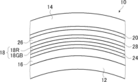
図1に示すウインドシールドガラス10は、第1ガラス12と第2ガラス14との間に、中間膜16と、偏光変換層24と、反射層18と、位相差層28と、透明基材26と、ヒートシール層20とを有するものである。反射層18は、コレステリック液晶層を有する。図示例において、反射層18は、コレステリック液晶層として、緑色青色反射コレステリック液晶層18GBおよび赤色反射コレステリック液晶層18Rを有する。
第1ガラス12は、本発明における第1の曲面ガラスである。また、第2ガラス14は、本発明における第2の曲面ガラスである。第2ガラス14は、凹面を第1ガラス12の凸面に向けて配置される。
また、図示例のウインドシールドガラス10は、第1ガラス12の凸面側に、中間膜16、偏光変換層24、反射層18、位相差層28、透明基材26、ヒートシール層20、ならびに、第2ガラス14が、この順番で配置される。偏光変換層24、反射層18および位相差層28によって、透明基材26付のハーフミラーフィルムが構成される。
以下の説明では、便宜的に、ウインドシールドガラス10において、第1ガラス12側を『下』、第2ガラス14側を『上』ともいう。
The
Further, the illustrated
In the following description, in the
なお、本発明のウインドシールドガラス10において、中間膜16、位相差層28、透明基材26、および、ヒートシール層20は、好ましい態様として設けられるもので、必須の構成要件ではない。
すなわち、本発明のウインドシールドガラスは、少なくとも、第1ガラス12と、偏光変換層24と、反射層18と、第2ガラス14とを有し、第1ガラス12の凸面側に、偏光変換層24、反射層18および第2ガラス14が、この順番で設けられれば良い。この構成では、偏光変換層24および反射層18によって、ハーフミラーフィルムが構成される。
従って、本発明のウインドシールドガラスは、第1ガラス12、偏光変換層24、反射層18および第2ガラス14のみで構成されてもよく、あるいは、これらに加えて、中間膜16、位相差層28、透明基材26およびヒートシール層20の1以上を、適宜、有するものであってもよい。
中間膜16、位相差層28、透明基材26およびヒートシール層20の、いずれを加えるかは、ウインドシールドガラスの用途、要求される性能、および、層構成等に応じて、適宜、選択すればよい。In the
That is, the windshield glass of the present invention has at least the
Therefore, the windshield glass of the present invention may be composed only of the
Which of the
<<第1ガラスおよび第2ガラス>>
上述のように、第1ガラス12は、本発明における第1の曲面ガラスである。また、第2ガラスは、本発明における第2の曲面ガラスである。
曲面ガラスである第1ガラス12および第2ガラス14を用いた合わせガラスである本発明のウインドシールドガラス10は、曲面の合わせガラスである。
上述のように、本発明のウインドシールドガラス10は、第1ガラス12の凸面側に、中間膜16、偏光変換層24、反射層18、位相差層28、透明基材26、ヒートシール層20、ならびに、第2ガラス14が、この順番で配置される。
一般的なウインドシールドガラスは、曲面ガラスである場合には、曲面の凹面側が、車内側の表面になる。従って、ウインドシールドガラス10は、第1ガラス12の凹面が車内側の表面、第2ガラス14の凸面が車外側の表面である。ウインドシールドガラス10において、後述するHUDの投映光は、第1ガラス12の凹面側から照射される。<<first glass and second glass>>
As described above, the
The
As described above, the
When the general windshield glass is curved glass, the concave side of the curved surface is the inner surface of the vehicle. Therefore, in the
第1ガラス12および第2ガラス14の形状には、制限はなく、曲面ガラス(曲面を有するガラス板)であれば、装着される車両等に応じて、ウインドシールドガラスとして用いることができる各種の形状が利用可能である。
従って、第1ガラス12および第2ガラス14は、全面が曲面であっても、曲面と平面とが混在するものであってもよい。また、第1ガラス12および第2ガラス14の曲面は、全面が同じ曲率であっても、異なる曲率の曲面が混在してもよい。The shapes of the
Therefore, the
第1ガラス12および第2ガラス14は、曲面ガラスであれば、ウインドシールドガラスに一般的に用いられるガラス板が利用可能である。
一例として、遮熱性の高いグリーンガラス等の、可視光透過率が73%および76%等の、80%以下であるガラス板が例示される。If the
One example is a glass plate having a visible light transmittance of 80% or less, such as 73% and 76%, such as green glass with high heat shielding properties.
第1ガラス12および第2ガラス14の厚さには、制限はなく、ガラス板の形成材料および形状等に応じて、十分な強度を得られる厚さを、適宜、設定すれば良い。
第1ガラス12および第2ガラス14の厚さは、0.5~5.0mmが好ましく、1.0~3.0mmがより好ましく、2.0~2.3mmがさらに好ましい。
なお、第1ガラス12および第2ガラス14の材料および/または厚さは、同じでも、異なってもよい。The thicknesses of the
The thickness of the
The materials and/or thicknesses of the
<<中間膜>>
第1ガラス12の凸面には、中間膜16が設けられる。上述のように、中間膜16は、好ましい態様として設けられるもので、第1ガラス12と偏光変換層24との間に設けられる。
中間膜16は、ウインドシールドガラスとして用いられる合わせガラスに用いられる、公知の中間膜である。従って、中間膜16は、第1ガラス12と後述する偏光変換層24とを貼着すると共に、事故が起きた際など、衝撃を受けた場合に、ガラスが車内に散乱すること、および、ウインドシールドガラス10に衝撃を与えた物が車内に突入すること等を防止する、耐衝撃性を確保する機能を有する。<<Intermediate film>>
An
The
中間膜16としては、ウインドシールドガラスとして用いられる合わせガラスに用いられる、公知の中間膜が、各種、利用可能である。
一例として、中間膜16としては、ポリビニルブチラール(PVB)、エチレン-酢酸ビニル共重合体、および、塩素含有樹脂等の樹脂を含む樹脂膜を用いることができる。上述の樹脂は、中間膜16の主成分であることが好ましい。なお、主成分であるとは、物を形成する成分の内の最も多い成分をいい、好ましくは、50質量%以上を占める成分のことをいう。As the
As an example, the
上述の樹脂のうち、ポリビニルブチラールおよびエチレン-酢酸ビニル共重合体が好ましく例示され、ポリビニルブチラールがより好ましく例示される。樹脂は、合成樹脂であることが好ましい。
ポリビニルブチラールは、ポリビニルアルコールをブチルアルデヒドによりアセタール化して得ることができる。上述のポリビニルブチラールのアセタール化度の好ましい下限は40%、好ましい上限は85%であり、より好ましい下限は60%、より好ましい上限は75%である。Among the above resins, polyvinyl butyral and ethylene-vinyl acetate copolymer are preferred, and polyvinyl butyral is more preferred. The resin is preferably a synthetic resin.
Polyvinyl butyral can be obtained by acetalizing polyvinyl alcohol with butyraldehyde. A preferable lower limit of the degree of acetalization of polyvinyl butyral is 40%, a preferable upper limit is 85%, a more preferable lower limit is 60%, and a more preferable upper limit is 75%.
ポリビニルアルコールは、通常、ポリ酢酸ビニルを鹸化することにより得られ、鹸化度80~99.8モル%のポリビニルアルコールが一般的に用いられる。
また、上述のポリビニルアルコールの重合度の好ましい下限は200、好ましい上限は3000である。ポリビニルアルコールの重合度が200以上であると、得られる合わせガラスの耐貫通性が低下しにくく、3000以下であると、樹脂膜の成形性がよく、しかも樹脂膜の剛性が大きくなり過ぎず、加工性が良好である。より好ましい下限は500、より好ましい上限は2000である。Polyvinyl alcohol is generally obtained by saponifying polyvinyl acetate, and polyvinyl alcohol having a degree of saponification of 80 to 99.8 mol % is generally used.
The preferred lower limit of the degree of polymerization of polyvinyl alcohol is 200, and the preferred upper limit is 3,000. When the degree of polymerization of polyvinyl alcohol is 200 or more, the penetration resistance of the resulting laminated glass is less likely to decrease. Good workability. A more preferable lower limit is 500, and a more preferable upper limit is 2,000.
本発明のウインドシールドガラス10において、中間膜16の厚さには、制限はない。中間膜16の厚さは、形成材料等に応じて、目的とする耐衝撃性および貼着力を得られる厚さを、適宜、設定すればよい。
中間膜16の厚さは、380~1500μmが好ましい。
中間膜16の厚さを380μm以上とすることにより、十分な耐衝撃性を得られる、第1ガラス12と偏光変換層24との十分な密着性が得られる、車内への紫外線遮光性を十分に得られる等の点で好ましい。中間膜16の厚さを1500μm以下とすることにより、ウインドシールドガラス10を薄くできる、ウインドシールドガラスの軽量化を図れる等の点で好ましい。
中間膜16の厚さは、500~1140μmがより好ましく、700~800μmがさらに好ましい。In the
The thickness of the
By setting the thickness of the
The thickness of the
中間膜16の上、すなわち、中間膜16と反射層18との間には、偏光変換層24が設けられる。
偏光変換層24は、液晶化合物の螺旋配向構造を固定化した層である。
偏光変換層24は、車内側の第1ガラス12側から入射したp偏光(直線偏光)を、円偏光に変換する。また、偏光変換層24は、反射層18(コレステリック液晶層)が反射した円偏光を、p偏光に変換する。
本発明のウインドシールドガラス10は、この偏光変換層24と反射層18としてのコレステリック液晶層とを組み合わせることで、p偏光による投映像を、高い輝度で投映することを可能にしている。
偏光変換層24に関しては、後に詳述する。A
The
The
The
The
<<反射層>>
偏光変換層24の上には、反射層18が設けられる。
反射層18は、コレステリック液晶相を固定してなるコレステリック液晶層を有する。従って、反射層18は、特定の波長域の光を選択的に反射する。
なお、本発明のウインドシールドガラス10において、反射層18すなわちコレステリック液晶層は、第1ガラス12の全面に対応して設けてもよく、第1ガラス12の一部に対応して設けてもよい。
HUDに対するウインドシールドガラス10の対応の容易性、反射層18を組み込む位置の精度等を考慮すると、本発明においては、反射層18は、第1ガラス12の全面に対応して設けることが好ましい。
この点に関しては、偏光変換層24および位相差層28も同様である。<<reflection layer>>
A
The
In the
Considering the ease of adapting the
In this regard, the same applies to the
図示例の反射層18は、緑色光および青色光を選択的に反射する緑色青色反射コレステリック液晶層18GBと、赤色光を選択的に反射する赤色反射コレステリック液晶層18Rとを有する。図示例の反射層18においては、一例として、偏光変換層24側から、緑色青色反射コレステリック液晶層18GB、赤色反射コレステリック液晶層18Rの順で積層している。
しかしながら、本発明のウインドシールドガラスは、これに制限はされず、様々なコレステリック液晶層、および、コレステリック液晶層の組み合わせが利用可能である。
一例として、本発明のウインドシールドガラスは、緑色青色反射コレステリック液晶層18GBのみを有するものでもよい。また、本発明のウインドシールドガラスは、赤色光と緑色光とを選択的に反射する赤色緑色反射コレステリック液晶層と、青色光を選択的に反射する青い反射コレステリック液晶層の2層を有するものでもよく、赤色緑色反射コレステリック液晶層のみを有するものでもよい。
また、本発明のウインドシールドガラスは、赤色反射コレステリック液晶層、緑色光を選択的に反射する緑色反射コレステリック液晶層、および、青色反射コレステリック液晶層の、3層のコレステリック液晶層を有するものでもよい。また、本発明のウインドシールドガラスは、赤色反射コレステリック液晶層、緑色反射コレステリック液晶層、および、青色反射コレステリック液晶層の内の1層のみを有するものでもよく、あるいは、適宜、選択して組み合わせた2層を有するものでもよい。
さらに、本発明のウインドシールドガラスは、1層で青色光、緑色光および赤色光の全てを反射するコレステリック液晶層を有するものでもよい。The illustrated
However, the windshield glass of the present invention is not limited to this, and various cholesteric liquid crystal layers and combinations of cholesteric liquid crystal layers can be used.
As an example, the windshield glass of the present invention may have only the green-blue reflecting cholesteric liquid crystal layer 18GB. Further, the windshield glass of the present invention may have two layers of a red-green reflecting cholesteric liquid crystal layer that selectively reflects red light and green light and a blue reflecting cholesteric liquid crystal layer that selectively reflects blue light. Alternatively, it may have only a red-green reflecting cholesteric liquid crystal layer.
Further, the windshield glass of the present invention may have three layers of cholesteric liquid crystal layers: a red-reflecting cholesteric liquid crystal layer, a green-reflecting cholesteric liquid crystal layer that selectively reflects green light, and a blue-reflecting cholesteric liquid crystal layer. . In addition, the windshield glass of the present invention may have only one layer of a red-reflecting cholesteric liquid crystal layer, a green-reflecting cholesteric liquid crystal layer, and a blue-reflecting cholesteric liquid crystal layer, or may have a combination thereof selected as appropriate. It may have two layers.
Furthermore, the windshield glass of the present invention may have a cholesteric liquid crystal layer that reflects all of blue light, green light and red light with a single layer.
ここで、コレステリック液晶層は、斜め光に対して、選択的な反射の中心波長が短波側にシフトすることが知られている。上述の反射の中心波長が短波側にシフトすることは、ブルーシフトと呼ばれている。斜め光では光干渉において各層間の光路長差が小さくなることが原因で、コレステリック液晶層でブルーシフトがおこる。従って、斜め方向から観察した場合、ブルーシフトが生じる。
このため、反射層18を構成するコレステリック液晶層は、反射の中心波長が短波側にシフトする分を予め補正して、選択反射層の正面における反射中心波長を長波側にずらすことが望ましい。斜め光の中心波長は、斜め光が選択反射層を伝播するときの正面からの角度をθとしたとき、斜め光の中心波長=正面での中心波長×cosθであり、これを考慮して反射中心波長をずらす構成とすることができる。上述の反射層18は、ブルーシフトを考慮して波長範囲が設定されている。Here, the cholesteric liquid crystal layer is known to shift the central wavelength of selective reflection to the short wavelength side with respect to oblique light. The above shift of the central wavelength of reflection to the short wave side is called blue shift. With oblique light, blue shift occurs in the cholesteric liquid crystal layer due to the fact that the optical path length difference between each layer becomes small in optical interference. Therefore, blue shift occurs when observed from an oblique direction.
Therefore, in the cholesteric liquid crystal layer constituting the
[コレステリック液晶層]
コレステリック液晶層は、コレステリック液晶相を固定した層である。
コレステリック液晶層は、コレステリック液晶相となっている液晶化合物の配向が保持されている層であればよい。コレステリック液晶層は、典型的には、重合性液晶化合物をコレステリック液晶相の配向状態としたうえで、紫外線照射および加熱等によって重合、硬化し、流動性が無い層を形成して、同時に、また外場または外力によって配向形態に変化を生じさせることがない状態に変化した層であればよい。なお、コレステリック液晶層においては、コレステリック液晶相の光学的性質が層中において保持されていれば十分であり、層中の液晶化合物は、もはや液晶性を示していなくてもよい。例えば、重合性液晶化合物は、硬化反応により高分子量化して、もはや液晶性を失っていてもよい。[Cholesteric liquid crystal layer]
A cholesteric liquid crystal layer is a layer in which a cholesteric liquid crystal phase is fixed.
The cholesteric liquid crystal layer may be any layer as long as the orientation of the liquid crystal compound in the cholesteric liquid crystal phase is maintained. A cholesteric liquid crystal layer is typically formed by aligning a polymerizable liquid crystal compound in a cholesteric liquid crystal phase, and then polymerizing and curing by ultraviolet irradiation, heating, or the like to form a layer having no fluidity, and at the same time, Any layer may be used as long as it is changed to a state in which the orientation is not changed by an external field or external force. In the cholesteric liquid crystal layer, it is sufficient that the optical properties of the cholesteric liquid crystal phase are maintained in the layer, and the liquid crystal compound in the layer may no longer exhibit liquid crystallinity. For example, the polymerizable liquid crystal compound may be polymerized by a curing reaction and no longer have liquid crystallinity.
コレステリック液晶相は、右円偏光または左円偏光のいずれか一方のセンスの円偏光を選択的に反射させると共に、他方のセンスの円偏光を透過する円偏光選択反射を示すことが知られている。
円偏光選択反射性を示すコレステリック液晶相を固定した層を含むフィルムとして、重合性液晶化合物を含む組成物から形成されたフィルムは従来から数多く知られており、コレステリック液晶層については、それらの従来技術を参照することができる。It is known that a cholesteric liquid crystal phase selectively reflects either right-handed circularly polarized light or left-handed circularly polarized light and transmits the other sense circularly polarized light. .
Many films formed from a composition containing a polymerizable liquid crystal compound are conventionally known as films containing a layer in which a cholesteric liquid crystal phase exhibiting selective reflection of circularly polarized light is fixed. You can refer to the technology.
コレステリック液晶層による選択反射の中心波長(選択反射中心波長)λは、コレステリック液晶相における螺旋配向構造のピッチP(=螺旋の周期)に依存し、コレステリック液晶層の平均屈折率nとλ=n×Pの関係に従う。この式からわかるように、n値および/またはP値を調節することにより、選択反射中心波長を調節することができる。
螺旋配向構造のピッチP(螺旋1ピッチ)とは、言い換えれば、螺旋の巻き数1回分の螺旋軸方向の長さであり、すなわち、コレステリック液晶相を構成する液晶化合物のダイレクター(棒状液晶であれば長軸方向)が360°回転する螺旋軸方向の長さである。通常のコレステリック液晶層の螺旋軸方向は、コレステリック液晶層の厚さ方向と一致する。The central wavelength of selective reflection by the cholesteric liquid crystal layer (selective reflection central wavelength) λ depends on the pitch P (= helical period) of the helical alignment structure in the cholesteric liquid crystal phase, and the average refractive index n and λ = n of the cholesteric liquid crystal layer It follows the relationship of ×P. As can be seen from this equation, the selective reflection center wavelength can be adjusted by adjusting the n value and/or the P value.
The pitch P of the helical alignment structure (one helical pitch) is, in other words, the length in the direction of the helical axis corresponding to one turn of the helical structure. is the length in the direction of the helical axis that rotates 360°. The helical axis direction of a normal cholesteric liquid crystal layer coincides with the thickness direction of the cholesteric liquid crystal layer.
コレステリック液晶層の選択反射中心波長および半値幅は、一例として、下記のように求めることができる。
分光光度計(日本分光社製、V-670)を用いて、法線方向からコレステリック液晶層の反射スペクトルを測定すると、選択反射帯域に透過率の低下ピークがみられる。このピークの極小透過率と低下前の透過率との中間(平均)の透過率となる2つの波長のうち、短波長側の波長の値をλl(nm)、長波長側の波長の値をλh(nm)とすると、選択反射中心波長λと半値幅Δλは下記式で表すことができる。
λ=(λl+λh)/2Δλ=(λh-λl)
上述のように求められる選択反射中心波長は、コレステリック液晶層の法線方向から測定した円偏光反射スペクトルの反射ピークの重心位置にある波長と略一致する。As an example, the selective reflection center wavelength and half width of the cholesteric liquid crystal layer can be obtained as follows.
When the reflection spectrum of the cholesteric liquid crystal layer is measured from the normal direction using a spectrophotometer (manufactured by JASCO Corporation, V-670), a transmittance drop peak is observed in the selective reflection band. Of the two wavelengths that have an intermediate (average) transmittance between the minimum transmittance of this peak and the transmittance before decrease, the wavelength on the short wavelength side is λ l (nm), and the wavelength on the long wavelength side is λ h (nm), the selective reflection central wavelength λ and the half width Δλ can be expressed by the following equations.
λ=( λl + λh )/2Δλ=( λh − λl )
The selective reflection center wavelength obtained as described above substantially coincides with the wavelength at the centroid position of the reflection peak of the circularly polarized reflection spectrum measured from the normal direction of the cholesteric liquid crystal layer.
後述する本発明のHUDにおいては、ウインドシールドガラス10に対して斜めに光が入射するように用いることにより、第1ガラス12の表面での反射率を低くすることができる。
この時、反射層18を構成するコレステリック液晶層に対しても斜めに光が入射する。例えば、屈折率1の空気中でウインドシールドガラス10の法線に対し45°~70°の角度で入射した光は、屈折率1.61程度のコレステリック液晶層を26°~36°程度の角度で透過する。この場合、反射波長は短波長側にシフトする。
選択反射中心波長が波長λであるコレステリック液晶層中で、コレステリック液晶層の法線方向(コレステリック液晶層の螺旋軸方向)に対して光線がθ2の角度で通過するときの選択反射中心波長を波長λdとするとき、波長λdは以下の式で表される。
λd=λ×cosθ2
In the HUD of the present invention, which will be described later, the reflectance on the surface of the
At this time, the light obliquely enters the cholesteric liquid crystal layer forming the
In a cholesteric liquid crystal layer with a selective reflection center wavelength of wavelength λ, the selective reflection center wavelength when a light ray passes at an angle of θ2 with respect to the normal direction of the cholesteric liquid crystal layer (spiral axis direction of the cholesteric liquid crystal layer) is When the wavelength is λ d , the wavelength λ d is expressed by the following formula.
λ d =λ×cos θ 2
そのため、θ2が26~36°のとき650~780nmの範囲に選択反射の中心波長を有するコレステリック液晶層は、520~695nmの範囲で投映光を反射することができる。
このような波長範囲は視感度の高い波長域であるため投映像の輝度への寄与度が高く、結果として高い輝度の投映像を実現することができる。Therefore, a cholesteric liquid crystal layer having a central wavelength of selective reflection in the range of 650 to 780 nm when θ 2 is 26 to 36° can reflect projection light in the range of 520 to 695 nm.
Since such a wavelength range is a wavelength range with high luminosity, it has a high degree of contribution to the luminance of a projected image, and as a result, a projected image with high luminance can be realized.
コレステリック液晶相の螺旋ピッチは、重合性液晶化合物とともに用いるキラル剤の種類、および、その添加濃度に依存するため、これらを調節することによって所望のピッチを得ることができる。なお、螺旋のセンスおよびピッチの測定法については「液晶化学実験入門」日本液晶学会編 シグマ出版2007年出版、46頁、および「液晶便覧」液晶便覧編集委員会 丸善 196頁に記載の方法を用いることができる。
Since the helical pitch of the cholesteric liquid crystal phase depends on the type of chiral agent used together with the polymerizable liquid crystal compound and the concentration thereof added, a desired pitch can be obtained by adjusting these. As for the method for measuring the sense and pitch of the helix, the method described in "Introduction to Liquid Crystal Chemistry Experiments" edited by the Japan Liquid Crystal Society, published by Sigma Publishing, 2007,
また、本発明のウインドシールドガラスにおいて、コレステリック液晶層は、視認側すなわち車内側から見て、選択反射の中心波長が短いものから順に配置されていることが好ましい。 Moreover, in the windshield glass of the present invention, the cholesteric liquid crystal layers are preferably arranged in order from the one having the shortest central wavelength of selective reflection when viewed from the viewing side, ie, the inside of the vehicle.
各コレステリック液晶層としては、螺旋のセンスが右または左のいずれかであるコレステリック液晶層が用いられる。コレステリック液晶層が反射する円偏光のセンス(円偏光の旋回方向)は、螺旋のセンスに一致する。
選択反射中心波長が異なる複数層のコレステリック液晶層を有する場合、各コレステリック液晶層の螺旋のセンスは、全て同じであっても、異なるものが含まれていてもよい。しかしながら、複数のコレステリック液晶層は、螺旋のセンスすなわち選択的に反射する円偏光の旋回方向が、全て同じであることが好ましい。For each cholesteric liquid crystal layer, a cholesteric liquid crystal layer with either right or left helix sense is used. The sense of circularly polarized light reflected by the cholesteric liquid crystal layer (the direction of rotation of the circularly polarized light) matches the sense of the helix.
In the case of having a plurality of cholesteric liquid crystal layers with different selective reflection center wavelengths, the helical sense of each cholesteric liquid crystal layer may be the same or different. However, it is preferable that all of the plurality of cholesteric liquid crystal layers have the same helical sense, that is, the rotating direction of the selectively reflected circularly polarized light.
また、ウインドシールドガラス10が反射層18として複数層のコレステリック液晶層を有する場合には、同一または重複する波長域で選択反射を示すコレステリック液晶層として、螺旋センスが異なるコレステリック液晶層を含まないことが好ましい。特定の波長域での透過率が例えば、50%未満に低下することを避けるためである。
When the
選択反射を示す選択反射帯の半値幅Δλ(nm)は、液晶化合物の複屈折Δnと上述のピッチPに依存し、Δλ=Δn×Pの関係に従う。そのため、選択反射帯の幅の制御は、Δnを調節して行うことができる。Δnの調節は重合性液晶化合物の種類または混合比率を調節したり、配向固定時の温度を制御したりすることで行うことができる。
選択反射の中心波長が同一の1種のコレステリック液晶層の形成のために、ピッチPが同じで、同じ螺旋のセンスのコレステリック液晶層を複数積層してもよい。ピッチPが同じで、同じ螺旋のセンスのコレステリック液晶層を積層することによって、特定の波長で円偏光選択性を高くすることができる。The half width Δλ (nm) of the selective reflection band indicating selective reflection depends on the birefringence Δn of the liquid crystal compound and the pitch P described above, and follows the relationship Δλ=Δn×P. Therefore, the width of the selective reflection band can be controlled by adjusting Δn. The Δn can be adjusted by adjusting the type or mixing ratio of the polymerizable liquid crystal compound, or by controlling the temperature during orientation fixation.
In order to form one type of cholesteric liquid crystal layer having the same center wavelength of selective reflection, a plurality of cholesteric liquid crystal layers having the same pitch P and the same spiral sense may be laminated. By stacking cholesteric liquid crystal layers with the same pitch P and the same helical sense, the circular polarization selectivity can be increased at a particular wavelength.
反射層18は、反射波長帯域が波長540~850nmの範囲内で、半値幅が150nm以上のコレステリック液晶層を有することが好ましい。コレステリック液晶層の半値幅を150nm以上とすることで、反射層18が広帯域の光を選択的に反射する選択反射層となる。その結果、ウインドシールドガラス10をHUD等に利用した際に、画像の輝度を高くすることができる。
The
反射層18において、複数のコレステリック液晶層を積層する際には、別に作製したコレステリック液晶層を、接着剤等を用いて積層してもよく、あるいは、後述する方法で形成された先のコレステリック液晶層の表面に、直接、重合性液晶化合物等を含む液晶組成物を塗布し、配向および固定の工程を繰り返してもよいが、後者が好ましい。
先に形成されたコレステリック液晶層の表面に直接次のコレステリック液晶層を形成することにより、先に形成したコレステリック液晶層の空気界面側の液晶分子の配向方位と、その上に形成するコレステリック液晶層の下側の液晶分子の配向方位が一致し、コレステリック液晶層の積層体の偏光特性が良好となるからである。また、接着層の厚さムラに由来して生じ得る干渉ムラが観測されないからである。When laminating a plurality of cholesteric liquid crystal layers in the
By forming the next cholesteric liquid crystal layer directly on the surface of the previously formed cholesteric liquid crystal layer, the alignment direction of the liquid crystal molecules on the air interface side of the previously formed cholesteric liquid crystal layer and the cholesteric liquid crystal layer formed thereon are changed. This is because the alignment directions of the liquid crystal molecules on the lower side are matched, and the polarizing property of the laminate of the cholesteric liquid crystal layers is improved. In addition, it is because interference unevenness that can be caused by thickness unevenness of the adhesive layer is not observed.
コレステリック液晶層の厚さは、0.5~10μmが好ましく、1.0~8.0μmがより好ましく、1.5~6.0μmがさらに好ましい。
また、ウインドシールドガラス10が複数のコレステリック液晶層を有する場合には、コレステリック液晶層の厚さの総計は、2.0~30μmが好ましく、2.5~25μmがより好ましく、3.0~20μmがさらに好ましい。
ウインドシールドガラス10においては、コレステリック液晶層の厚さを低減することなく、可視光線透過率を高く維持することができる。The thickness of the cholesteric liquid crystal layer is preferably 0.5 to 10 μm, more preferably 1.0 to 8.0 μm, even more preferably 1.5 to 6.0 μm.
Further, when the
In the
(コレステリック液晶層の形成方法)
以下、コレステリック液晶層の形成材料および形成方法について説明する。
上述のコレステリック液晶層の形成に用いる材料としては、重合性液晶化合物とキラル剤(光学活性化合物)とを含む液晶組成物(塗布液)等が挙げられる。必要に応じて、さらに、界面活性剤および重合開始剤等と混合して溶剤等に溶解した液晶組成物を、支持体、配向層、下層となるコレステリック液晶層等に塗布し、コレステリック配向熟成後、液晶組成物の硬化により固定化してコレステリック液晶層を形成することができる。(Method for Forming Cholesteric Liquid Crystal Layer)
The material and method for forming the cholesteric liquid crystal layer will be described below.
Examples of materials used for forming the cholesteric liquid crystal layer include a liquid crystal composition (coating liquid) containing a polymerizable liquid crystal compound and a chiral agent (optically active compound). If necessary, a liquid crystal composition mixed with a surfactant, a polymerization initiator, and the like and dissolved in a solvent or the like is applied to the support, the alignment layer, the underlying cholesteric liquid crystal layer, etc., and after cholesteric orientation aging. can be fixed by curing the liquid crystal composition to form a cholesteric liquid crystal layer.
(重合性液晶化合物)
重合性液晶化合物は、棒状液晶化合物であっても、円盤状液晶化合物であってもよいが、棒状液晶化合物であることが好ましい。
コレステリック液晶層を形成する棒状の重合性液晶化合物の例としては、棒状ネマチック液晶化合物が挙げられる。棒状ネマチック液晶化合物としては、アゾメチン類、アゾキシ類、シアノビフェニル類、シアノフェニルエステル類、安息香酸エステル類、シクロヘキサンカルボン酸フェニルエステル類、シアノフェニルシクロヘキサン類、シアノ置換フェニルピリミジン類、アルコキシ置換フェニルピリミジン類、フェニルジオキサン類、トラン類、および、アルケニルシクロヘキシルベンゾニトリル類が好ましく用いられる。低分子液晶化合物だけではなく、高分子液晶化合物も用いることができる。(Polymerizable liquid crystal compound)
The polymerizable liquid crystal compound may be a rod-like liquid crystal compound or a discotic liquid crystal compound, but is preferably a rod-like liquid crystal compound.
An example of the rod-like polymerizable liquid crystal compound forming the cholesteric liquid crystal layer is a rod-like nematic liquid crystal compound. Rod-shaped nematic liquid crystal compounds include azomethines, azoxys, cyanobiphenyls, cyanophenyl esters, benzoic acid esters, cyclohexanecarboxylic acid phenyl esters, cyanophenylcyclohexanes, cyano-substituted phenylpyrimidines, and alkoxy-substituted phenylpyrimidines. , phenyldioxanes, tolanes, and alkenylcyclohexylbenzonitriles are preferably used. Not only low-molecular-weight liquid crystal compounds but also high-molecular liquid-crystal compounds can be used.
重合性液晶化合物は、重合性基を液晶化合物に導入することで得られる。重合性基の例には、不飽和重合性基、エポキシ基、および、アジリジニル基が含まれ、不飽和重合性基が好ましく、エチレン性不飽和重合性基が特に好ましい。重合性基は種々の方法で、液晶化合物の分子中に導入できる。重合性液晶化合物が有する重合性基の個数は、好ましくは一分子中に1~6個、より好ましくは1~3個である。
重合性液晶化合物の例は、Makromol.Chem.,190巻、2255頁(1989年)、Advanced Materials 5巻、107頁(1993年)、米国特許第4683327号明細書、米国特許第5622648号明細書、米国特許第5770107号明細書、WO95/22586、WO95/24455、WO97/00600、WO98/23580、WO98/52905、特開平1-272551号公報、特開平6-16616号公報、特開平7-110469号公報、特開平11-80081号公報、および、特開2001-328973号公報等に記載の化合物が含まれる。2種類以上の重合性液晶化合物を併用してもよい。2種類以上の重合性液晶化合物を併用すると、配向温度を低下させることができる。A polymerizable liquid crystal compound is obtained by introducing a polymerizable group into a liquid crystal compound. Examples of polymerizable groups include unsaturated polymerizable groups, epoxy groups, and aziridinyl groups, with unsaturated polymerizable groups being preferred, and ethylenically unsaturated polymerizable groups being particularly preferred. Polymerizable groups can be introduced into molecules of liquid crystal compounds by various methods. The number of polymerizable groups possessed by the polymerizable liquid crystal compound is preferably 1 to 6, more preferably 1 to 3, in one molecule.
Examples of polymerizable liquid crystal compounds are described in Makromol. Chem. , 190, 2255 (1989); Advanced Materials 5, 107 (1993); U.S. Pat. No. 4,683,327; U.S. Pat. No. 5,622,648; U.S. Pat. , WO95/24455, WO97/00600, WO98/23580, WO98/52905, JP-A-1-272551, JP-A-6-16616, JP-A-7-110469, JP-A-11-80081, and , and compounds described in JP-A-2001-328973. Two or more types of polymerizable liquid crystal compounds may be used in combination. When two or more kinds of polymerizable liquid crystal compounds are used together, the alignment temperature can be lowered.
また、液晶組成物中の重合性液晶化合物の添加量は、液晶組成物の固形分質量(溶媒を除いた質量)に対して、80~99.9質量%が好ましく、85~99.5質量%がより好ましく、90~99質量%が特に好ましい。 Further, the amount of the polymerizable liquid crystal compound added in the liquid crystal composition is preferably 80 to 99.9% by mass, and preferably 85 to 99.5% by mass, based on the solid content mass (mass excluding the solvent) of the liquid crystal composition. % is more preferable, and 90 to 99% by mass is particularly preferable.
可視光透過率を向上させるためには、緑色青色反射コレステリック液晶層18GBは低Δnであってもよい。低Δnの緑色青色反射コレステリック液晶層18GBは、低Δn重合性液晶化合物を用いて形成することができる。以下、低Δn重合性液晶化合物について具体的に説明する。 In order to improve the visible light transmittance, the green blue reflecting cholesteric liquid crystal layer 18GB may have a low Δn. The low Δn green-blue reflective cholesteric liquid crystal layer 18GB can be formed using a low Δn polymerizable liquid crystal compound. The low Δn polymerizable liquid crystal compound will be specifically described below.
(低Δn重合性液晶化合物)
低Δn重合性液晶化合物を利用してコレステリック液晶相を形成し、これを固定したフィルムとすることにより、狭帯域選択反射層を得ることができる。低Δn重合性液晶化合物の例としては、WO2015/115390、WO2015/147243、WO2016/035873、特開2015-163596号公報、特開2016-53149号公報に記載の化合物が挙げられる。半値幅の小さい選択反射層を与える液晶組成物については、WO2016/047648の記載も参照できる。(Low Δn polymerizable liquid crystal compound)
A narrow-band selective reflection layer can be obtained by forming a cholesteric liquid crystal phase using a low Δn polymerizable liquid crystal compound and fixing it to a film. Examples of low Δn polymerizable liquid crystal compounds include compounds described in WO2015/115390, WO2015/147243, WO2016/035873, JP-A-2015-163596, and JP-A-2016-53149. The description of WO2016/047648 can also be referred to for the liquid crystal composition that provides a selective reflection layer with a small half-value width.
液晶化合物は、WO2016/047648に記載の以下の式(I)で表される重合性化合物であることも好ましい。 The liquid crystal compound is also preferably a polymerizable compound represented by the following formula (I) described in WO2016/047648.

式(I)中、Aは、置換基を有していてもよいフェニレン基または置換基を有していてもよいトランス-1,4-シクロヘキシレン基を示し、Lは単結合、-CH2O-、-OCH2-、-(CH2)2OC(=O)-、-C(=O)O(CH2)2-、-C(=O)O-、-OC(=O)-、-OC(=O)O-、-CH=CH-C(=O)O-、および-OC(=O)-CH=CH-からなる群から選択される連結基を示し、mは3~12の整数を示し、Sp1およびSp2はそれぞれ独立に、単結合、炭素数1から20の直鎖もしくは分岐のアルキレン基、および炭素数1から20の直鎖もしくは分岐のアルキレン基において1つまたは2つ以上の-CH2-が-O-、-S-、-NH-、-N(CH3)-、-C(=O)-、-OC(=O)-、または-C(=O)O-で置換された基からなる群から選択される連結基を示し、Q1およびQ2はそれぞれ独立に、水素原子または以下の式Q-1~式Q-5で表される基からなる群から選択される重合性基を示し、ただしQ1およびQ2のいずれか一方は重合性基を示す。In formula (I), A represents an optionally substituted phenylene group or an optionally substituted trans-1,4-cyclohexylene group, L is a single bond, —CH 2 O-, -OCH 2 -, -(CH 2 ) 2 OC(=O)-, -C(=O)O(CH 2 ) 2 -, -C(=O)O-, -OC(=O) -, -OC(=O)O-, -CH=CH-C(=O)O-, and -OC(=O)-CH=CH-, and m represents a linking group selected from the group consisting of represents an integer of 3 to 12, and Sp 1 and Sp 2 are each independently a single bond, a linear or branched alkylene group having 1 to 20 carbon atoms, and a linear or branched alkylene group having 1 to 20 carbon atoms; one or more of -CH 2 - are -O-, -S-, -NH-, -N(CH 3 )-, -C(=O)-, -OC(=O)-, or - represents a linking group selected from the group consisting of groups substituted with C(=O)O-, wherein Q 1 and Q 2 are each independently a hydrogen atom or represented by formulas Q-1 to Q-5 below; wherein either one of Q 1 and Q 2 represents a polymerizable group.

式(I)中の、フェニレン基は1,4-フェニレン基であることが好ましい。
フェニレン基およびトランス-1,4-シクロヘキシレン基について「置換基を有していてもよい」というときの置換基は、特に限定されず、例えば、アルキル基、シクロアルキル基、アルコキシ基、アルキルエーテル基、アミド基、アミノ基、およびハロゲン原子ならびに、上述の置換基を2つ以上組み合わせて構成される基からなる群から選択される置換基が挙げられる。また、置換基の例としては、後述の-C(=O)-X3-Sp3-Q3で表される置換基が挙げられる。フェニレン基およびトランス-1,4-シクロヘキシレン基は、置換基を1~4個有していてもよい。2個以上の置換基を有するとき、2個以上の置換基は互いに同一であっても異なっていてもよい。The phenylene group in formula (I) is preferably a 1,4-phenylene group.
Regarding the phenylene group and the trans-1,4-cyclohexylene group, the substituent when "optionally having a substituent" is not particularly limited, and examples thereof include alkyl groups, cycloalkyl groups, alkoxy groups, alkyl ether groups, amido groups, amino groups, halogen atoms, and substituents selected from the group consisting of a combination of two or more of the above substituents. Examples of substituents include substituents represented by -C(=O)-X 3 -Sp 3 -Q 3 described later. The phenylene group and trans-1,4-cyclohexylene group may have 1 to 4 substituents. When having two or more substituents, the two or more substituents may be the same or different.
アルキル基は直鎖状および分岐鎖状のいずれでもよい。アルキル基の炭素数は1~30が好ましく、1~10がより好ましく、1~6がさらに好ましい。アルキル基の例としては、例えば、メチル基、エチル基、n-プロピル基、イソプロピル基、n-ブチル基、イソブチル基、sec-ブチル基、tert-ブチル基、n-ペンチル基、イソペンチル基、ネオペンチル基、1,1-ジメチルプロピル基、n-ヘキシル基、イソヘキシル基、直鎖状または分岐鎖状のヘプチル基、オクチル基、ノニル基、デシル基、ウンデシル基、またはドデシル基を挙げることができる。アルキル基に関する上述の説明はアルキル基を含むアルコキシ基においても同様である。また、アルキレン基というときのアルキレン基の具体例としては、上述のアルキル基の例それぞれにおいて、任意の水素原子を1つ除いて得られる2価の基等が挙げられる。ハロゲン原子としては、フッ素原子、塩素原子、臭素原子、およびヨウ素原子が挙げられる。 Alkyl groups may be linear or branched. The number of carbon atoms in the alkyl group is preferably 1-30, more preferably 1-10, even more preferably 1-6. Examples of alkyl groups include methyl, ethyl, n-propyl, isopropyl, n-butyl, isobutyl, sec-butyl, tert-butyl, n-pentyl, isopentyl, and neopentyl. 1,1-dimethylpropyl, n-hexyl, isohexyl, linear or branched heptyl, octyl, nonyl, decyl, undecyl or dodecyl radicals. The above description regarding alkyl groups also applies to alkoxy groups containing alkyl groups. Further, specific examples of the alkylene group when referred to as an alkylene group include a divalent group obtained by removing one arbitrary hydrogen atom in each of the examples of the above-mentioned alkyl groups, and the like. Halogen atoms include fluorine, chlorine, bromine, and iodine atoms.
シクロアルキル基の炭素数は、3~20が好ましく、5以上がより好ましく、また、10以下が好ましく、8以下がより好ましく、6以下がさらに好ましい。シクロアルキル基の例としては、シクロプロピル基、シクロブチル基、シクロペンチル基、シクロヘキシル基、シクロヘプチル基、シクロオクチル基を挙げることができる。 The number of carbon atoms in the cycloalkyl group is preferably 3 to 20, more preferably 5 or more, preferably 10 or less, more preferably 8 or less, and even more preferably 6 or less. Examples of cycloalkyl groups include cyclopropyl, cyclobutyl, cyclopentyl, cyclohexyl, cycloheptyl and cyclooctyl groups.
フェニレン基およびトランス-1,4-シクロヘキシレン基が有していてもよい置換基としては特に、アルキル基、およびアルコキシ基、-C(=O)-X3-Sp3-Q3からなる群から選択される置換基が好ましい。ここで、X3は単結合、-O-、-S-、もしくは-N(Sp4-Q4)-を示すか、または、Q3およびSp3と共に環構造を形成している窒素原子を示す。Sp3、Sp4はそれぞれ独立に、単結合、炭素数1から20の直鎖もしくは分岐のアルキレン基、および炭素数1から20の直鎖もしくは分岐のアルキレン基において1つまたは2つ以上の-CH2-が-O-、-S-、-NH-、-N(CH3)-、-C(=O)-、-OC(=O)-、または-C(=O)O-で置換された基からなる群から選択される連結基を示す。Substituents which the phenylene group and the trans-1,4-cyclohexylene group may have are particularly the group consisting of an alkyl group, an alkoxy group, and -C(=O)-X 3 -Sp 3 -Q 3 Substituents selected from are preferred. Here, X 3 represents a single bond, —O—, —S—, or —N(Sp 4 —Q 4 )—, or represents a nitrogen atom forming a ring structure together with Q 3 and Sp 3 show. Sp 3 and Sp 4 are each independently a single bond, a linear or branched alkylene group having 1 to 20 carbon atoms, and a linear or branched alkylene group having 1 to 20 carbon atoms, and one or more of - CH 2 - is -O-, -S-, -NH-, -N(CH 3 )-, -C(=O)-, -OC(=O)-, or -C(=O)O- A linking group selected from the group consisting of substituted groups is shown.
Q3およびQ4はそれぞれ独立に、水素原子、シクロアルキル基、シクロアルキル基において1つもしくは2つ以上の-CH2-が-O-、-S-、-NH-、-N(CH3)-、-C(=O)-、-OC(=O)-、もしくは-C(=O)O-で置換された基、または式Q-1~式Q-5で表される基からなる群から選択されるいずれかの重合性基を示す。Each of Q 3 and Q 4 is independently a hydrogen atom, a cycloalkyl group, or a cycloalkyl group in which one or more —CH 2 — are —O—, —S—, —NH—, —N(CH 3 )-, -C(=O)-, -OC(=O)-, or a group substituted with -C(=O)O-, or a group represented by formulas Q-1 to Q-5 represents any polymerizable group selected from the group consisting of
シクロアルキル基において1つまたは2つ以上の-CH2-が-O-、-S-、-NH-、-N(CH3)-、-C(=O)-、-OC(=O)-、または-C(=O)O-で置換された基として、具体的には、テトラヒドロフラニル基、ピロリジニル基、イミダゾリジニル基、ピラゾリジニル基、ピペリジル基、ピペラジニル基、および、モルホルニル基等が挙げられる。置換位置は特に限定されない。これらのうち、テトラヒドロフラニル基が好ましく、特に2-テトラヒドロフラニル基が好ましい。one or more -CH 2 - in the cycloalkyl group is -O-, -S-, -NH-, -N(CH 3 )-, -C(=O)-, -OC(=O); Specific examples of groups substituted with - or -C(=O)O- include a tetrahydrofuranyl group, a pyrrolidinyl group, an imidazolidinyl group, a pyrazolidinyl group, a piperidyl group, a piperazinyl group, and a morphonyl group. . The substitution position is not particularly limited. Among these, a tetrahydrofuranyl group is preferred, and a 2-tetrahydrofuranyl group is particularly preferred.
式(I)において、Lは単結合、-CH2O-、-OCH2-、-(CH2)2OC(=O)-、-C(=O)O(CH2)2-、-C(=O)O-、-OC(=O)-、-OC(=O)O-、-CH=CH-C(=O)O-、および、-OC(=O)-CH=CH-からなる群から選択される連結基を示す。Lは-C(=O)O-または-OC(=O)-であることが好ましい。m-1個のLは互いに同一でも異なっていてもよい。In formula (I), L is a single bond, -CH 2 O-, -OCH 2- , -(CH 2 ) 2 OC(=O)-, -C(=O)O(CH 2 ) 2 -,- C(=O)O-, -OC(=O)-, -OC(=O)O-, -CH=CH-C(=O)O-, and -OC(=O)-CH=CH represents a linking group selected from the group consisting of -. L is preferably -C(=O)O- or -OC(=O)-. m−1 Ls may be the same or different.
Sp1、Sp2はそれぞれ独立に、単結合、炭素数1から20の直鎖もしくは分岐のアルキレン基、および炭素数1から20の直鎖もしくは分岐のアルキレン基において1つまたは2つ以上の-CH2-が-O-、-S-、-NH-、-N(CH3)-、-C(=O)-、-OC(=O)-、または-C(=O)O-で置換された基からなる群から選択される連結基を示す。Sp1およびSp2はそれぞれ独立に、両末端にそれぞれ-O-、-OC(=O)-、および-C(=O)O-からなる群から選択される連結基が結合した炭素数1から10の直鎖のアルキレン基、-OC(=O)-、-C(=O)O-、-O-、および炭素数1から10の直鎖のアルキレン基からなる群から選択される基を1または2以上組み合わせて構成される連結基であることが好ましく、両方の末端に-O-がそれぞれ結合した炭素数1から10の直鎖のアルキレン基であることが好ましい。Sp 1 and Sp 2 are each independently a single bond, a linear or branched alkylene group having 1 to 20 carbon atoms, and a linear or branched alkylene group having 1 to 20 carbon atoms, and one or more of - CH 2 - is -O-, -S-, -NH-, -N(CH 3 )-, -C(=O)-, -OC(=O)-, or -C(=O)O- A linking group selected from the group consisting of substituted groups is shown. Each of Sp 1 and Sp 2 is independently a 1 carbon atom having a linking group selected from the group consisting of -O-, -OC(=O)-, and -C(=O)O- at both ends. A group selected from the group consisting of straight-chain alkylene groups of from to 10, -OC(=O)-, -C(=O)O-, -O-, and straight-chain alkylene groups of 1 to 10 carbon atoms is preferably a linking group constituted by combining one or two or more of and is preferably a linear alkylene group having 1 to 10 carbon atoms and having —O— attached to both ends.
Q1およびQ2はそれぞれ独立に、水素原子、もしくは上述の式Q-1~式Q-5で表される基からなる群から選択される重合性基を示し、ただしQ1およびQ2のいずれか一方は重合性基を示す。
重合性基としては、アクリロイル基(式Q-1)またはメタクリロイル基(式Q-2)が好ましい。Q 1 and Q 2 each independently represents a hydrogen atom or a polymerizable group selected from the group consisting of the groups represented by the above formulas Q-1 to Q-5, provided that Q 1 and Q 2 Either one represents a polymerizable group.
As the polymerizable group, an acryloyl group (formula Q-1) or a methacryloyl group (formula Q-2) is preferred.
式(I)中、mは、3~12の整数を示す。mは、3~9の整数が好ましく、3~7の整数がより好ましく、3~5の整数がさらに好ましい。 In formula (I), m represents an integer of 3-12. m is preferably an integer of 3 to 9, more preferably an integer of 3 to 7, and even more preferably an integer of 3 to 5.
式(I)で表される重合性化合物は、Aとして置換基を有していてもよいフェニレン基を少なくとも1つおよび置換基を有していてもよいトランス-1,4-シクロヘキシレン基を少なくとも1つ含むことが好ましい。式(I)で表される重合性化合物は、Aとして、置換基を有していてもよいトランス-1,4-シクロヘキシレン基を1~4個含むことが好ましく、1~3個含むことがより好ましく、2または3個含むことがさらに好ましい。また、式(I)で表される重合性化合物は、Aとして、置換基を有していてもよいフェニレン基を1個以上含むことが好ましく、1~4個含むことがより好ましく、1~3個含むことがさらに好ましく、2個または3個含むことが特に好ましい。 The polymerizable compound represented by formula (I) has at least one optionally substituted phenylene group as A and an optionally substituted trans-1,4-cyclohexylene group. It is preferable to include at least one. The polymerizable compound represented by formula (I) preferably contains 1 to 4 trans-1,4-cyclohexylene groups which may have a substituent as A, and preferably contains 1 to 3 groups. is more preferred, and 2 or 3 is even more preferred. Further, the polymerizable compound represented by the formula (I) preferably contains one or more phenylene groups which may have a substituent as A, more preferably contains 1 to 4 groups, 1 to It is more preferable to contain 3, and it is particularly preferable to contain 2 or 3.
式(I)において、Aで表されるトランス-1,4-シクロヘキシレン基の数をmで割った数をmcとしたとき、0.1<mc<0.9が好ましく、0.3<mc<0.8がより好ましく、0.5<mc<0.7がさらに好ましい。液晶組成物が0.5<mc<0.7である式(I)で表される重合性化合物とともに、0.1<mc<0.3である式(I)で表される重合性化合物を含むことも好ましい。 In formula (I), when mc is the number obtained by dividing the number of trans-1,4-cyclohexylene groups represented by A by m, 0.1<mc<0.9 is preferable, and 0.3< mc<0.8 is more preferred, and 0.5<mc<0.7 is even more preferred. The polymerizable compound represented by the formula (I) having a liquid crystal composition satisfying 0.5<mc<0.7 and the polymerizable compound represented by the formula (I) satisfying 0.1<mc<0.3 It is also preferred to include
式(I)で表される重合性化合物の例として具体的には、WO2016/047648の段落0051~0058に記載の化合物のほか、特開2013-112631号公報、特開2010-70543号公報、特許4725516号、WO2015/115390、WO2015/147243、WO2016/035873、特開2015-163596号公報、および、特開2016-53149号公報に記載の化合物等を挙げることができる。 Specific examples of the polymerizable compound represented by formula (I) include, in addition to the compounds described in paragraphs 0051 to 0058 of WO2016/047648, JP-A-2013-112631, JP-A-2010-70543, Japanese Patent No. 4725516, WO2015/115390, WO2015/147243, WO2016/035873, JP-A-2015-163596, and compounds described in JP-A-2016-53149.
(キラル剤:光学活性化合物)
キラル剤はコレステリック液晶相の螺旋配向構造を誘起する機能を有する。キラル化合物は、化合物によって誘起する螺旋のセンスまたは螺旋ピッチが異なるため、目的に応じて選択すればよい。
キラル剤としては、特に制限はなく、公知の化合物を用いることができる。キラル剤の例としては、液晶デバイスハンドブック(第3章4-3項、TN、STN用カイラル剤、199頁、日本学術振興会第142委員会編、1989)、特開2003-287623号、特開2002-302487号、特開2002-80478号、特開2002-80851号、特開2010-181852号、および、特開2014-034581号等の各公報に記載の化合物が挙げられる。(Chiral Agent: Optically Active Compound)
A chiral agent has a function of inducing a helical alignment structure of a cholesteric liquid crystal phase. The chiral compound may be selected according to the purpose, since the helical sense or helical pitch induced by the compound differs.
The chiral agent is not particularly limited, and known compounds can be used. Examples of chiral agents include Liquid Crystal Device Handbook (Chapter 3, Section 4-3, Chiral Agents for TN and STN, p. Examples include compounds described in JP-A-2002-302487, JP-A-2002-80478, JP-A-2002-80851, JP-A-2010-181852, and JP-A-2014-034581.
キラル剤は、一般に不斉炭素原子を含むが、不斉炭素原子を含まない軸性不斉化合物あるいは面性不斉化合物も、キラル剤として用いることができる。軸性不斉化合物または面性不斉化合物の例には、ビナフチル、ヘリセン、パラシクロファン、および、これらの誘導体が含まれる。
キラル剤は、重合性基を有していてもよい。キラル剤と液晶化合物とがいずれも重合性基を有する場合は、重合性キラル剤と重合性液晶化合物との重合反応により、重合性液晶化合物から誘導される繰り返し単位と、キラル剤から誘導される繰り返し単位とを有するポリマーを形成することができる。この態様では、重合性キラル剤が有する重合性基は、重合性液晶化合物が有する重合性基と、同種の基であることが好ましい。従って、キラル剤の重合性基も、不飽和重合性基、エポキシ基またはアジリジニル基であることが好ましく、不飽和重合性基であることがさらに好ましく、エチレン性不飽和重合性基であることが特に好ましい。
また、キラル剤は、液晶化合物であってもよい。A chiral agent generally contains an asymmetric carbon atom, but an axially chiral compound or planar asymmetric compound that does not contain an asymmetric carbon atom can also be used as a chiral agent. Examples of axially or planarly chiral compounds include binaphthyl, helicene, paracyclophane, and derivatives thereof.
The chiral agent may have a polymerizable group. When both the chiral agent and the liquid crystal compound have a polymerizable group, a repeating unit derived from the polymerizable liquid crystal compound and a repeating unit derived from the chiral agent are formed by the polymerization reaction of the polymerizable chiral agent and the polymerizable liquid crystal compound. A polymer having repeating units can be formed. In this aspect, the polymerizable group possessed by the polymerizable chiral agent is preferably the same type of group as the polymerizable group possessed by the polymerizable liquid crystal compound. Therefore, the polymerizable group of the chiral agent is also preferably an unsaturated polymerizable group, an epoxy group or an aziridinyl group, more preferably an unsaturated polymerizable group, and an ethylenically unsaturated polymerizable group. Especially preferred.
Also, the chiral agent may be a liquid crystal compound.
キラル剤としては、イソソルビド誘導体、イソマンニド誘導体、および、ビナフチル誘導体等を好ましく用いることができる。イソソルビド誘導体としては、BASF社製のLC756等の市販品を用いてもよい。
液晶組成物における、キラル剤の含有量は、重合性液晶化合物量の0.01~200モル%が好ましく、1~30モル%がより好ましい。なお、液晶組成物中におけるキラル剤の含有量は、組成物中の全固形分に対するキラル剤の濃度(質量%)を意図する。As the chiral agent, isosorbide derivatives, isomannide derivatives, binaphthyl derivatives, and the like can be preferably used. As the isosorbide derivative, a commercially available product such as LC756 manufactured by BASF may be used.
The content of the chiral agent in the liquid crystal composition is preferably 0.01 to 200 mol %, more preferably 1 to 30 mol % of the amount of the polymerizable liquid crystal compound. In addition, the content of the chiral agent in the liquid crystal composition intends the concentration (% by mass) of the chiral agent with respect to the total solid content in the composition.
(重合開始剤)
液晶組成物は、重合開始剤を含有していることが好ましい。紫外線照射により重合反応を進行させる態様では、使用する重合開始剤は、紫外線照射によって重合反応を開始可能な光重合開始剤であることが好ましい。
光重合開始剤の例には、α-カルボニル化合物(米国特許第2367661号、米国特許第2367670号の各明細書記載)、アシロインエーテル(米国特許第2448828号明細書記載)、α-炭化水素置換芳香族アシロイン化合物(米国特許第2722512号明細書記載)、多核キノン化合物(米国特許第3046127号、米国特許第2951758号の各明細書記載)、トリアリールイミダゾールダイマーとp-アミノフェニルケトンとの組み合わせ(米国特許第3549367号明細書記載)、アクリジンおよびフェナジン化合物(特開昭60-105667号公報、米国特許第4239850号明細書記載)、アシルフォスフィンオキシド化合物(特公昭63-40799号公報、特公平5-29234号公報、特開平10-95788号公報、特開平10-29997号公報、特開2001-233842号公報、特開2000-80068号公報、特開2006-342166号公報、特開2013-114249号公報、特開2014-137466号公報、特許4223071号公報、特開2010-262028号公報、特表2014-500852号公報記載)、オキシム化合物(特開2000-66385号公報、特許第4454067号公報記載)、および、オキサジアゾール化合物(米国特許第4212970号明細書記載)等が挙げられる。例えば、特開2012-208494号公報の段落0500~0547の記載も参酌できる。(Polymerization initiator)
The liquid crystal composition preferably contains a polymerization initiator. In the embodiment in which the polymerization reaction is advanced by ultraviolet irradiation, the polymerization initiator used is preferably a photopolymerization initiator capable of initiating the polymerization reaction by ultraviolet irradiation.
Examples of photoinitiators include α-carbonyl compounds (described in US Pat. Nos. 2,367,661 and 2,367,670), acyloin ethers (described in US Pat. No. 2,448,828), α-hydrocarbons substituted aromatic acyloin compounds (described in US Pat. No. 2,722,512), polynuclear quinone compounds (described in US Pat. Nos. 3,046,127 and 2,951,758), triarylimidazole dimers and p-aminophenyl ketone combination (described in US Pat. No. 3,549,367), acridine and phenazine compound (described in JP-A-60-105667, US Pat. No. 4,239,850), acylphosphine oxide compound (JP-B-63-40799, JP-B-5-29234, JP-A-10-95788, JP-A-10-29997, JP-A-2001-233842, JP-A-2000-80068, JP-A-2006-342166, JP-A 2013-114249, JP 2014-137466, JP 4223071, JP 2010-262028, JP 2014-500852), oxime compound (JP 2000-66385, Patent No. No. 4,454,067) and oxadiazole compounds (described in US Pat. No. 4,212,970). For example, paragraphs 0500 to 0547 of JP-A-2012-208494 can also be referred to.
重合開始剤としては、アシルフォスフィンオキシド化合物またはオキシム化合物を用いることも好ましい。
アシルフォスフィンオキシド化合物としては、例えば、市販品のBASFジャパン社製のIRGACURE810(化合物名:ビス(2,4,6-トリメチルベンゾイル)-フェニルフォスフィンオキサイド)を用いることができる。オキシム化合物としては、IRGACURE OXE01(BASF社製)、IRGACURE OXE02(BASF社製)、TR-PBG-304(常州強力電子新材料有限公司製)、アデカアークルズNCI-831、アデカアークルズNCI-930(ADEKA社製)、および、アデカアークルズNCI-831(ADEKA社製)等の市販品を用いることができる。
重合開始剤は、1種のみ用いてもよいし、2種以上を併用してもよい。
液晶組成物中の光重合開始剤の含有量は、重合性液晶化合物の含有量に対して0.1~20質量%が好ましく、0.5~5質量%がより好ましい。As the polymerization initiator, it is also preferable to use an acylphosphine oxide compound or an oxime compound.
As the acylphosphine oxide compound, for example, a commercial product, IRGACURE810 (compound name: bis(2,4,6-trimethylbenzoyl)-phenylphosphine oxide) manufactured by BASF Japan, can be used. Examples of oxime compounds include IRGACURE OXE01 (manufactured by BASF), IRGACURE OXE02 (manufactured by BASF), TR-PBG-304 (manufactured by Changzhou Tenryu Electric New Materials Co., Ltd.), Adeka Arkles NCI-831, and Adeka Arkles NCI-930. (manufactured by ADEKA), and ADEKA Arkles NCI-831 (manufactured by ADEKA).
Only one polymerization initiator may be used, or two or more polymerization initiators may be used in combination.
The content of the photopolymerization initiator in the liquid crystal composition is preferably 0.1 to 20% by mass, more preferably 0.5 to 5% by mass, based on the content of the polymerizable liquid crystal compound.
(架橋剤)
液晶組成物は、硬化後の膜強度向上、耐久性向上のため、任意に架橋剤を含有していてもよい。架橋剤としては、紫外線、熱、湿気等で硬化するものが好適に使用できる。
架橋剤としては、特に制限はなく、目的に応じて適宜選択することができる。架橋剤としては、例えば、トリメチロールプロパントリ(メタ)アクリレート、ペンタエリスリトールトリ(メタ)アクリレート等の多官能アクリレート化合物;グリシジル(メタ)アクリレート、エチレングリコールジグリシジルエーテル等のエポキシ化合物;2,2-ビスヒドロキシメチルブタノール-トリス[3-(1-アジリジニル)プロピオネート]、4,4-ビス(エチレンイミノカルボニルアミノ)ジフェニルメタン等のアジリジン化合物;ヘキサメチレンジイソシアネート、ビウレット型イソシアネート等のイソシアネート化合物;オキサゾリン基を側鎖に有するポリオキサゾリン化合物;ビニルトリメトキシシラン、N-(2-アミノエチル)3-アミノプロピルトリメトキシシラン等のアルコキシシラン化合物等が挙げられる。また、架橋剤の反応性に応じて公知の触媒を用いることができ、膜強度および耐久性向上に加えて生産性を向上させることができる。これらは、1種単独で使用してもよいし、2種以上を併用してもよい。
架橋剤の含有量は、3~20質量%が好ましく、5~15質量%がより好ましい。架橋剤の含有量を3質量%以上とすることにより、架橋密度向上の効果を得ることができ、架橋剤の含有量を20質量%以下とすることにより、コレステリック液晶層の安定性の低下を防止できる。
なお、「(メタ)アクリレート」は、「アクリレートおよびメタクリレートのいずれか一方または双方」の意味で使用される。(crosslinking agent)
The liquid crystal composition may optionally contain a cross-linking agent in order to improve film strength and durability after curing. As the cross-linking agent, one that is cured by ultraviolet rays, heat, humidity, or the like can be preferably used.
The cross-linking agent is not particularly limited and can be appropriately selected depending on the purpose. Examples of cross-linking agents include polyfunctional acrylate compounds such as trimethylolpropane tri (meth) acrylate and pentaerythritol tri (meth) acrylate; epoxy compounds such as glycidyl (meth) acrylate and ethylene glycol diglycidyl ether; aziridine compounds such as bishydroxymethylbutanol-tris[3-(1-aziridinyl)propionate], 4,4-bis(ethyleneiminocarbonylamino)diphenylmethane; isocyanate compounds such as hexamethylene diisocyanate and biuret type isocyanate; polyoxazoline compounds having chains; alkoxysilane compounds such as vinyltrimethoxysilane and N-(2-aminoethyl)3-aminopropyltrimethoxysilane; Also, a known catalyst can be used depending on the reactivity of the cross-linking agent, and productivity can be improved in addition to the enhancement of membrane strength and durability. These may be used individually by 1 type, and may use 2 or more types together.
The content of the cross-linking agent is preferably 3 to 20% by mass, more preferably 5 to 15% by mass. By setting the content of the cross-linking agent to 3% by mass or more, the effect of improving the cross-linking density can be obtained, and by setting the content of the cross-linking agent to 20% by mass or less, the decrease in stability of the cholesteric liquid crystal layer can be prevented. can be prevented.
In addition, "(meth)acrylate" is used in the sense of "one or both of acrylate and methacrylate".
(配向制御剤)
液晶組成物中には、安定的にまたは迅速にプレーナー配向のコレステリック液晶層とするために寄与する配向制御剤を添加してもよい。配向制御剤の例としては、特開2007-272185号公報の段落[0018]~[0043]等に記載のフッ素(メタ)アクリレート系ポリマー、特開2012-203237号公報の段落[0031]~[0034]等に記載の式(I)~(IV)で表される化合物、および、特開2013-113913号公報に記載の化合物等が挙げられる。
なお、配向制御剤としては1種を単独で用いてもよいし、2種以上を併用してもよい。(Orientation control agent)
An alignment control agent may be added to the liquid crystal composition to contribute to stably or rapidly forming a planar alignment cholesteric liquid crystal layer. Examples of alignment control agents include fluorine (meth)acrylate polymers described in paragraphs [0018] to [0043] of JP-A-2007-272185, paragraphs [0031] to [0031] of JP-A-2012-203237. 0034] and the like, compounds represented by formulas (I) to (IV), and compounds described in JP-A-2013-113913.
As the alignment control agent, one type may be used alone, or two or more types may be used in combination.
液晶組成物中における、配向制御剤の添加量は、重合性液晶化合物の全質量に対して0.01~10質量%が好ましく、0.01~5質量%がより好ましく、0.02~1質量%が特に好ましい。 The amount of the alignment control agent added in the liquid crystal composition is preferably 0.01 to 10% by mass, more preferably 0.01 to 5% by mass, and more preferably 0.02 to 1% based on the total mass of the polymerizable liquid crystal compound. % by weight is particularly preferred.
(その他の添加剤)
その他、液晶組成物は、塗膜の表面張力を調節し厚さを均一にするための界面活性剤、および重合性モノマー等の種々の添加剤から選ばれる少なくとも1種を含有していてもよい。また、液晶組成物中には、必要に応じて、さらに重合禁止剤、酸化防止剤、紫外線吸収剤、光安定化剤、色材、および、金属酸化物微粒子等を、光学性能を低下させない範囲で添加することができる。(Other additives)
In addition, the liquid crystal composition may contain at least one selected from various additives such as a surfactant for adjusting the surface tension of the coating film to make the thickness uniform, and a polymerizable monomer. . In addition, if necessary, the liquid crystal composition may further contain polymerization inhibitors, antioxidants, ultraviolet absorbers, light stabilizers, colorants, metal oxide fine particles, etc. to the extent that the optical performance is not reduced. can be added at
コレステリック液晶層は、重合性液晶化合物およびキラル剤、さらに必要に応じて添加される重合開始剤および界面活性剤等を溶媒に溶解させた液晶組成物を、後述する透明基材26、位相差層28、配向膜、または、先に作製されたコレステリック液晶層等の上に塗布し、乾燥させて塗膜を得、この塗膜に活性光線を照射してコレステリック液晶性組成物を重合し、コレステリック規則性が固定化されたコレステリック液晶層を形成することができる。
なお、複数のコレステリック液晶層からなる積層膜は、コレステリック液晶層の上述の製造工程を繰り返し行うことにより形成することができる。The cholesteric liquid crystal layer is a liquid crystal composition obtained by dissolving a polymerizable liquid crystal compound and a chiral agent, and optionally a polymerization initiator, a surfactant, and the like in a solvent, and a
A laminated film composed of a plurality of cholesteric liquid crystal layers can be formed by repeating the above-described manufacturing process of the cholesteric liquid crystal layer.
(溶媒)
液晶組成物の調製に使用する溶媒には、特に制限はなく、目的に応じて適宜選択することができるが、有機溶媒が好ましく用いられる。
有機溶媒には、特に制限はなく、目的に応じて適宜選択することができ、例えば、ケトン類、アルキルハライド類、アミド類、スルホキシド類、ヘテロ環化合物、炭化水素類、エステル類、および、エーテル類等が挙げられる。これらは、1種単独で使用してもよいし、2種以上を併用してもよい。これらの中でも、環境への負荷を考慮した場合にはケトン類が特に好ましい。(solvent)
The solvent used for preparing the liquid crystal composition is not particularly limited and can be appropriately selected according to the purpose, but organic solvents are preferably used.
The organic solvent is not particularly limited and can be appropriately selected depending on the purpose. Examples include ketones, alkyl halides, amides, sulfoxides, heterocyclic compounds, hydrocarbons, esters and ethers and the like. These may be used individually by 1 type, and may use 2 or more types together. Among these, ketones are particularly preferred in consideration of the load on the environment.
(塗布、配向、重合)
支持体、配向層、下層となるコレステリック液晶層等への液晶組成物の塗布方法には、特に制限はなく、目的に応じて適宜選択することができる。塗布方法としては、例えば、ワイヤーバーコーティング法、カーテンコーティング法、押し出しコーティング法、ダイレクトグラビアコーティング法、リバースグラビアコーティング法、ダイコーティング法、スピンコーティング法、ディップコーティング法、スプレーコーティング法、および、スライドコーティング法等が挙げられる。また、別途支持体上に塗設した液晶組成物を転写することによっても実施できる。
塗布した液晶組成物を加熱することにより、液晶分子を配向させる。加熱温度は、200℃以下が好ましく、130℃以下がより好ましい。この配向処理により、重合性液晶化合物が、フィルム面に対して実質的に垂直な方向に螺旋軸を有するようにねじれ配向している光学薄膜が得られる。(coating, orientation, polymerization)
The method of applying the liquid crystal composition to the support, the alignment layer, the underlying cholesteric liquid crystal layer, etc. is not particularly limited and can be appropriately selected according to the purpose. Examples of coating methods include wire bar coating, curtain coating, extrusion coating, direct gravure coating, reverse gravure coating, die coating, spin coating, dip coating, spray coating, and slide coating. law, etc. It can also be carried out by transferring a liquid crystal composition separately coated on a support.
The liquid crystal molecules are aligned by heating the applied liquid crystal composition. The heating temperature is preferably 200° C. or lower, more preferably 130° C. or lower. By this orientation treatment, an optical thin film is obtained in which the polymerizable liquid crystal compound is twisted so as to have a helical axis in a direction substantially perpendicular to the film surface.
配向させた液晶化合物をさらに重合させることにより、液晶組成物を硬化することができる。重合は、熱重合、光照射を利用する光重合のいずれでもよいが、光重合が好ましい。光照射は、紫外線を用いることが好ましい。照射エネルギーは、20mJ/cm2~50J/cm2が好ましく、100~1,500mJ/cm2がより好ましい。
光重合反応を促進するため、加熱条件下または窒素雰囲気下で光照射を実施してもよい。照射紫外線波長は350~430nmが好ましい。重合反応率は安定性の観点から、高いほうが好ましく70%以上が好ましく、80%以上がより好ましい。重合反応率は、重合性の官能基の消費割合を赤外線吸収スペクトルの測定により、決定することができる。By further polymerizing the oriented liquid crystal compound, the liquid crystal composition can be cured. Polymerization may be either thermal polymerization or photopolymerization using light irradiation, but photopolymerization is preferred. It is preferable to use ultraviolet rays for light irradiation. The irradiation energy is preferably 20 mJ/cm 2 to 50 J/cm 2 , more preferably 100 to 1,500 mJ/cm 2 .
In order to accelerate the photopolymerization reaction, light irradiation may be performed under heating conditions or under a nitrogen atmosphere. The irradiation ultraviolet wavelength is preferably 350 to 430 nm. From the viewpoint of stability, the polymerization reaction rate is preferably as high as 70% or more, more preferably 80% or more. The polymerization reaction rate can be determined by measuring the consumption rate of the polymerizable functional groups by infrared absorption spectrum measurement.
<<偏光変換層>>
本発明のウインドシールドガラス10は、曲面ガラスである第1ガラス12の凸面側に、偏光変換層24と、上述したコレステリック液晶層を有する反射層18と、第2ガラス14とを、この順番で有する。
後述するが、本発明のHUDにおいて、プロジェクターは、好ましい態様としてp偏光の投映光を照射して、ウインドシールドガラス10に入射する。
一方、本発明のウインドシールドガラス10は、コレステリック液晶相を固定してなるコレステリック液晶層を有する反射層18によって、投映光を反射する。上述のように、コレステリック液晶層は、基本的に、右円偏光または左円偏光を、選択的に反射する。
偏光変換層24は、プロジェクターから照射されたp偏光(直線偏光)を、コレステリック液晶層が選択的に反射する右円偏光または左円偏光に変換するものである。<<polarization conversion layer>>
The
As will be described later, in the HUD of the present invention, the projector irradiates p-polarized projection light as a preferred embodiment to enter the
On the other hand, the
The
偏光変換層24は、液晶化合物の螺旋配向構造を固定化した層であって、螺旋配向構造のピッチ数x、および、膜厚y[μm]が、下記の関係式(a)~(c)の全てを満足するものである。
(a)0.1≦x≦1.0
(b)0.5≦y≦3.0
(c)3000≦(1560*y)/x≦50000
上述したコレステリック液晶層と同様、偏光変換層24を構成する液晶化合物の螺旋配向構造において、螺旋配向構造のピッチ(螺旋1ピッチ)とは、螺旋の巻き数1回分の螺旋軸方向の長さであり、言い換えれば、液晶化合物のダイレクター(棒状液晶であれば長軸方向)が360°回転する螺旋軸方向の長さである。
すなわち、液晶化合物の螺旋配向構造のピッチ数1とは、螺旋の巻き数1回分である。言い換えれば、偏光変換層24を構成する液晶化合物のダイレクター360°回転した状態を、ピッチ数1とする。The
(a) 0.1≤x≤1.0
(b) 0.5≤y≤3.0
(c) 3000≦(1560*y)/x≦50000
As in the cholesteric liquid crystal layer described above, in the helical alignment structure of the liquid crystal compound that constitutes the
That is, the number of pitches of 1 in the helical alignment structure of the liquid crystal compound is one turn of the spiral. In other words, the pitch number is 1 when the director of the liquid crystal compound constituting the
このような偏光変換層24は、厚さが0.5~3μmで、この厚さの中にピッチ数が0.1~1ピッチである螺旋配向構造を有する。
すなわち、この偏光変換層24は、螺旋配向構造のピッチが、選択反射中心波長が長波長の赤外域であるコレステリック液晶層のピッチPに対応する長さである。このような偏光変換層24は、赤外域に対して短波長である可視光に対して、高い旋光性と複屈折性を発現する。
そのため、この偏光変換層24は、第1ガラス12側から入射したp偏光(直線偏光)を、反射層18が選択的に反射する右円偏光または左円偏光に変換できる。また、偏光変換層24は、反射層18によって反射された円偏光を、p偏光に戻して、運転者の観察位置に投映光を照射できる。Such a
That is, in the
Therefore, the
上述したように、水たまりの反射光、対向車のウインドシールドガラスの反射光、および、ボンネットの反射光など、車両等においてウインドシールドガラスの外部から侵入する、いわゆるギラツキとなる成分は、多くがs偏光である。そのため、偏光サングラスは、s偏光を遮光するようにされている。
従って、従来のs偏光を投映するHUDでは、運転者が偏光サングラスを着用した場合には、HUDの投映光を観察できない。
これに対し、本発明のウインドシールドガラス10およびHUDによれば、運転者による投映像の観察位置に、p偏光の投映光で照射できる。そのため、本発明のウインドシールドガラス10によれば、p偏光の投映像を投映できるので、運転者が偏光サングラスを着用した場合でも、HUDの投映像を好適に観察できる。As described above, many of the so-called glare components that enter from the outside of the windshield glass of a vehicle, such as reflected light from a puddle, reflected light from the windshield glass of an oncoming vehicle, and reflected light from the hood, are s Polarization. Therefore, polarized sunglasses are designed to block s-polarized light.
Therefore, with a conventional HUD that projects s-polarized light, the projected light from the HUD cannot be observed when the driver wears polarized sunglasses.
In contrast, according to the
また、本発明のウインドシールドガラス10は、偏光サングラスを着用した状態でのHUDによる投映像の観察を可能にするのみならず、車外から入射するギラツキとなる外光に対する偏光サングラス適性も良好である。
In addition, the
HUDにおいて、p偏光による投映光の投映が可能にする構成として、特許文献1に記載されるように、コレステリック液晶層とλ/2板などの位相差層とを組み合わせたハーフミラーフィルムを用いるウインドシールドガラスを用いる構成が知られている。
上述のように、このウインドシールドガラスは、入射したp偏光を位相差層で円偏光に変換し、この円偏光をコレステリック液晶層で反射して、この反射光を位相差層でp偏光に戻して投映光として照射する。これにより、運転者が偏光サングラスを着用している場合でも、HUDの投映像を観察することが可能になる。In the HUD, as described in Patent Document 1, a half-mirror film that combines a cholesteric liquid crystal layer and a retardation layer such as a λ/2 plate is used as a configuration that enables projection of p-polarized light. A configuration using shield glass is known.
As described above, this windshield glass converts incident p-polarized light into circularly polarized light with the retardation layer, reflects this circularly polarized light with the cholesteric liquid crystal layer, and converts the reflected light back into p-polarized light with the retardation layer. illuminate as projection light. As a result, even when the driver is wearing polarized sunglasses, the projected image of the HUD can be observed.
コレステリック液晶層に反射成分ではない偏光が入射して透過すると、偏光状態が変化する。
上述のように、ウインドシールドガラスの外部から侵入するギラツキ成分は、s偏光である。従って、p偏光に対応する円偏光を選択的に反射するコレステリック液晶層を透過したs偏光は、理想的には、s偏光に対応する旋回方向の円偏光になる。この円偏光は、次いで、位相差層によって、再度、s偏光に変換される。そのため、ウインドシールドガラスの外部から侵入するギラツキ成分であるs偏光は、偏光サングラスを用いることで、遮光できる。When polarized light other than the reflected component is incident on the cholesteric liquid crystal layer and is transmitted through the layer, the polarization state changes.
As described above, the glare component entering the windshield glass from the outside is s-polarized light. Therefore, the s-polarized light transmitted through the cholesteric liquid crystal layer that selectively reflects the circularly polarized light corresponding to the p-polarized light ideally becomes circularly polarized light in the rotation direction corresponding to the s-polarized light. This circularly polarized light is then converted back into s-polarized light by the retardation layer. Therefore, s-polarized light, which is a glare component entering the windshield glass from the outside, can be blocked by using polarized sunglasses.
ところが、外部からウインドシールドガラスに入射するs偏光は、ウインドシールドガラスのコレステリック液晶層に法線方向から入射する成分のみではなく、様々な角度でウインドシールドガラスに入射する。そのため、特許文献1に示されるような、従来の位相差層およびコレステリック液晶層によってp偏光を投映するHUDでは、外部から侵入して、コレステリック液晶層を透過したs偏光は、円偏光ではなく、楕円偏光になってしまう。
このような楕円偏光が位相差層を透過すると、透過光には、s偏光のみならず、p偏光の成分も混在してしまう。p偏光は、偏光サングラスで遮光できないので、偏光サングラスを透過してしまう。
そのため、従来のp偏光を投映するHUDでは、s偏光が主成分である、ギラツキとなる反射光を遮光する偏光サングラスの機能が損なわれ、運転の支障となる。すなわち、特許文献1に示されるような、従来のp偏光を投映する、位相差層および円偏光反射層を用いるハーフミラーフィルムを利用するウインドシールドガラスは、外光に対する偏光サングラス適性が低い。However, the s-polarized light incident on the windshield glass from the outside is incident on the windshield glass at various angles in addition to the component incident on the cholesteric liquid crystal layer of the windshield glass from the normal direction. Therefore, in a HUD that projects p-polarized light by a conventional retardation layer and a cholesteric liquid crystal layer, as shown in Patent Document 1, the s-polarized light that enters from the outside and passes through the cholesteric liquid crystal layer is not circularly polarized light. It becomes elliptically polarized.
When such elliptically polarized light is transmitted through the retardation layer, the transmitted light includes not only s-polarized light but also p-polarized light. Since p-polarized light cannot be blocked by polarized sunglasses, it passes through polarized sunglasses.
As a result, in a conventional HUD that projects p-polarized light, the function of polarized sunglasses to block glare reflected light, which is mainly composed of s-polarized light, is impaired, which hinders driving. That is, the conventional windshield glass that projects p-polarized light and uses a half-mirror film using a retardation layer and a circularly polarized light reflecting layer, as disclosed in Patent Document 1, has low suitability for polarized sunglasses against external light.
これに対して、本発明のウインドシールドガラスは、p偏光(直線偏光)を円偏光に変換する素子として、一般的に用いられる位相差層ではなく、上述のように、液晶化合物の螺旋配向構造を固定化した偏光変換層24を用いる。
本発明のウインドシールドガラスは、反射層18すなわちコレステリック液晶層よりも車内側に、このような偏光変換層24を有することにより、ギラツキとなる、車外から侵入し、反射層18によってs偏光から変換されたp偏光成分を、再度、s偏光に戻すことができる。
すなわち、本発明のウインドシールドガラス10によれば、車外から侵入する、ギラツキとなるs偏光を、s偏光の状態を保った状態で通過させることができる。そのため、後に実施例でも示すが、本発明のウインドシールドガラス10によれば、ギラツキとなる車外から入射したs偏光を偏光サングラスで遮光することができ、外光に対する優れた偏光サングラス適性を発現する。On the other hand, the windshield glass of the present invention is not a retardation layer generally used as an element for converting p-polarized light (linearly polarized light) into circularly polarized light, but has a helical orientation structure of a liquid crystal compound as described above. is fixed in the
The windshield glass of the present invention has such a
That is, according to the
なお、偏光変換層24における螺旋配向構造の旋回方向(螺旋のセンス)は、反射層18を構成するコレステリック液晶層が選択的に反射する円偏光の旋回方向に応じて設定すればよい。
例えば、コレステリック液晶層が右円偏光を選択的に反射する場合には、偏光変換層24の螺旋の旋回方向は、反射層18に向かって右回りとする。逆に、コレステリック液晶層が左円偏光を選択的に反射する場合には、偏光変換層24の螺旋の旋回方向は、反射層18に向かって左回りとする。The direction of rotation (sense of spiral) of the helical alignment structure in the
For example, when the cholesteric liquid crystal layer selectively reflects right-handed circularly polarized light, the spiral direction of the
上述のように、本発明のウインドシールドガラス10において、偏光変換層24は、螺旋配向構造のピッチ数xおよび膜厚yが、関係式(a)~(c)を全て満たす。
関係式(a)は、『0.1≦x≦1.0』である。
螺旋配向構造のピッチ数xが0.1未満では、十分な旋光性および複屈折性が得られない等の不都合を生じる。
また、螺旋配向構造のピッチ数xが1.0を超えると、旋光性および複屈折性が過剰で、所望の円偏光が得られない等の不都合を生じる。As described above, in the
Relational expression (a) is "0.1≤x≤1.0".
If the pitch number x of the helical orientation structure is less than 0.1, problems such as insufficient optical rotation and birefringence will occur.
On the other hand, if the pitch number x of the helical orientation structure exceeds 1.0, the optical rotatory power and birefringence are excessive, resulting in problems such as failure to obtain desired circularly polarized light.
関係式(b)は、『0.5≦y≦3.0』である。
偏光変換層24の厚さyが0.5μm未満では、膜厚が薄すぎて、十分な旋光性および複屈折性が得られない等の不都合を生じる。
偏光変換層24の厚さyが3.0μmを超えると、旋光性および複屈折性が過剰で、所望の楕円偏光が得られない等の不都合を生じる。The relational expression (b) is "0.5≤y≤3.0".
If the thickness y of the
If the thickness y of the
関係式(c)は、『3000≦(1560*y)/x≦50000』である。
偏光変換層24の螺旋配向構造のピッチ数xおよび厚さy[μm]をパラメータとする『(1560*y)/x』が3000未満では、旋光性が過剰で、所望の偏光が得られない等の不都合が生じる。
『(1560*y)/x』が50000を超えると、旋光性が不十分で、所望の偏光が得られない等の不都合を生じる。The relational expression (c) is "3000≤(1560*y)/x≤50000".
If "(1560*y)/x", in which the pitch number x and the thickness y [μm] of the helical orientation structure of the
If "(1560*y)/x" exceeds 50,000, the optical rotatory power is insufficient, resulting in problems such as failure to obtain desired polarized light.
本発明のウインドシールドガラス10において、偏光変換層24は、下記の関係式(d)~(f)を全て満たすことが好ましい。
(d)0.2≦x≦0.8
(e)0.6≦y≦2.0
(f)6000≦(1560*y)/x≦10000In the
(d) 0.2≤x≤0.8
(e) 0.6≤y≤2.0
(f) 6000≦(1560*y)/x≦10000
すなわち、偏光変換層24は、より螺旋配向構造のピッチPが長く、かつ、よりピッチ数xが少ないことが好ましい。
具体的には、偏光変換層24は、螺旋のピッチPが、選択反射中心波長が長波長の赤外域であるコレステリック液晶層のピッチPと同等で、かつ、ピッチ数xが少ないことが好ましい。より具体的には、偏光変換層24は、螺旋のピッチPが、選択反射中心波長が3000~8000nmであるコレステリック液晶層のピッチPと同等で、かつ、ピッチ数xが少ないことが好ましい。
このような偏光変換層24は、ピッチPが対応する選択反射中心波長が、可視光よりも遥かに長波長であるため、上述した可視光に対する旋光性と複屈折性を、より好適に発現する。That is, it is preferable that the
Specifically, the
In such a
このような偏光変換層24は、基本的に、上述したコレステリック液晶層と同様に形成できる。
ただし、偏光変換層24を形成する際には、偏光変換層24における螺旋配向構造のピッチ数xおよび膜厚y[μm]が、関係式(a)~(c)を全て満たすように、好ましくは関係式(d)~(f)を全て満たすように、使用する液晶化合物、使用するキラル剤、キラル剤の添加量、および、膜厚等を調節する必要がある。Such a
However, when forming the
<<位相差層>>
図示例のウインドシールドガラス10において、反射層18の上には、位相差層28が設けられる。上述のように、位相差層28は、好ましい態様として設けられるもので、反射層18(コレステリック液晶層)と第2ガラス14との間に設けられる。ウインドシールドガラスが透明基材26およびヒートシール層20を有する場合には、図示例の様に、位相差層28は、両者よりも反射層18よりに設けられることが好ましい。
本発明において、位相差層28は、波長550nmにおける正面リタデーションが50~170nmであり、好ましくは50~140nmである。また、位相差層28は、ウインドシールドガラスを車両に装着した際における、第1ガラス12の表面における鉛直方向の上方に対応する方向を0°(基準)とした際に、遅相軸が±10~50°の角度となるものである。
後述する図3を参照すると、矢印H方向が鉛直方向であるとして、矢印H方向の上方に向かう方向を0°とし、矢印Saを遅相軸とすると、位相差層28は、遅相軸の角度αが±10~50°となるようにする。<<retardation layer>>
In the illustrated
In the present invention, the
3, which will be described later, the direction of the arrow H is the vertical direction, the upward direction of the arrow H is 0°, and the arrow Sa is the slow axis. The angle α should be ±10 to 50°.
上述のように、本発明のウインドシールドガラス10は、反射層18(コレステリック液晶層)よりも車内側に偏光変換層24を有することにより、車外から入射したギラツキとなるs偏光を、s偏光を保って透過することができる、外光に対する、良好な偏光サングラス適性を有する。
本発明のウインドシールドガラス10は、好ましい態様として、この位相差層28を有することにより、車外から入射したギラツキとなるs偏光を、より好適にs偏光を保って透過させことができ、外光に対する偏光サングラス適性を、より向上できる。As described above, the
As a preferred embodiment, the
上述したように、水たまりの反射光、対向車のウインドシールドガラスの反射光、および、ボンネットの反射光など、車外から侵入する、いわゆるギラツキとなる成分は、多くがs偏光である。そのため、偏光サングラスは、s偏光を遮光するようにされている。
ところが、車外から侵入したs偏光は、反射層18を構成するコレステリック液晶層を通過する際に、光の偏光が変化して、p偏光の成分が混在してしまう。
偏光サングラスはs偏光を遮光するので、このp偏光の成分は、偏光サングラスを透過してしまう。そのため、従来のp偏光で投映像を表示するHUDでは、車外から入射する反射光のギラツキを遮光する偏光サングラスの機能が損なわれ、運転の支障となる問題がある。As described above, most of the so-called glare components entering from outside the vehicle, such as reflected light from puddles, reflected light from the windshield of oncoming vehicles, and reflected light from the hood, are s-polarized light. Therefore, polarized sunglasses are designed to block s-polarized light.
However, when the s-polarized light entering from outside the vehicle passes through the cholesteric liquid crystal layer forming the
Since polarized sunglasses block s-polarized light, this p-polarized component is transmitted through polarized sunglasses. Therefore, in a conventional HUD that displays a projected image with p-polarized light, the function of polarized sunglasses to block the glare of reflected light incident from outside the vehicle is impaired, which poses a problem that hinders driving.
これに対して、本発明のウインドシールドガラス10は、好ましくは、反射層18すなわちコレステリック液晶層と第2ガラス14との間に、位相差層28を有する。これにより、車外から入射するギラツキとなるs偏光は、コレステリック液晶層に入射する前に、位相差層28に入射する。
位相差層28に入射したギラツキとなるs偏光は、位相差層28の位相差によって、s偏光に応じた旋回方向の楕円偏光に変換される。
位相差層28を透過した楕円偏光は、次いで、反射層18すなわちコレステリック液晶層に入射する。s偏光から変換された楕円偏光は、旋回方向がコレステリック液晶層による反射成分ではないので、コレステリック液晶層を透過して、s偏光に対応する旋回方向の円偏光に変換される。この円偏光は、次いで、偏光変換層24を透過することにより、s偏光に変換され、ウインドシールドガラス10を透過する。
すなわち、本発明のウインドシールドガラス10が位相差層28を有することにより、ウインドシールドガラスの車外から侵入した、ギラツキとなるs偏光は、より好適にs偏光のまま透過するので、偏光サングラスによって遮光できる。従って、本発明のウインドシールドガラス10が位相差層28を有することにより、p偏光を投映するHUDにおいて、より好適に外光に対する偏光サングラス適性を向上できる。In contrast, the
The glaring s-polarized light incident on the
The elliptically polarized light transmitted through the
That is, since the
本発明のウインドシールドガラス10に用いられる位相差層28は、波長550nmにおける正面リタデーションが50~170nmであり、好ましくは50~140nmである。
正面リタデーションが50~170nmであり、好ましくは50~140nmであれば、複屈折性が適切で、外光のs偏光を適切な楕円偏光に変換することができるため好ましい。
位相差層28の正面リタデーションは、70~130nmがより好ましく、90~130nmがさらに好ましく、90~120nmが特に好ましい。The
When the front retardation is 50 to 170 nm, preferably 50 to 140 nm, the birefringence is appropriate, and the s-polarized light of external light can be converted into appropriate elliptically polarized light.
The front retardation of the
また、本発明のウインドシールドガラス10に用いられる位相差層28は、第1ガラス12の表面における鉛直方向の上方に対応する方向を0°とした際に、遅相軸の角度が±10~50°である。
遅相軸の角度が±10~50°であれば、外光のs偏光を適切な楕円偏光に変換することができるため好ましい。
遅相軸の角度は、±15~48°が好ましく、±30~45°がより好ましい。Further, the
If the angle of the slow axis is ±10 to 50°, the s-polarized light of the external light can be converted into an appropriate elliptically polarized light, which is preferable.
The angle of the slow axis is preferably ±15 to 48°, more preferably ±30 to 45°.
位相差層28の遅相軸の角度の『+』/『-』は、コレステリック液晶層の螺旋の捩れ方向(センス)すなわち選択的に反射する円偏光の旋回方向によって決定する。
具体的には、コレステリック液晶層が右円偏光を選択的に反射する場合には、遅相軸の角度は『+』、左円偏光を選択的に反射する場合には『-』である。
なお、位相差層28の遅相軸の角度は、0°に対して時計回りが『+』、反時計回りが『-』プラスである。The "+"/"-" angle of the slow axis of the
Specifically, when the cholesteric liquid crystal layer selectively reflects right-handed circularly polarized light, the angle of the slow axis is "+", and when it selectively reflects left-handed circularly polarized light, it is "-".
The angle of the slow axis of the
本発明のウインドシールドガラス10において、位相差層28には制限はなく、目的に応じて適宜選択することができる。
位相差層28としては、例えば、延伸されたポリカーボネートフィルム、延伸されたノルボルネン系ポリマーフィルム、炭酸ストロンチウムのような複屈折を有する無機粒子を含有して配向させた透明フィルム、支持体上に無機誘電体を斜め蒸着した薄膜、重合性液晶化合物を一軸配向させて配向固定したフィルム、および、液晶化合物を一軸配向させて配向固定したフィルム等が挙げられる。In the
As the
中でも、重合性液晶化合物を一軸配向させて配向固定したフィルムは、位相差層28として、好適に例示される。
このような位相差層28は、一例として、仮支持体、または配向層表面に、重合性液晶化合物を含む液晶組成物を塗布し、そこで液晶組成物中の重合性液晶化合物を液晶状態においてネマチック配向に形成後、硬化によって固定化して、形成することができる。
この場合の位相差層28の形成は、液晶組成物中にキラル剤を添加しない以外は、上述のコレステリック液晶層の形成と同様に行うことができる。ただし、液晶組成物の塗布後のネマチック配向の際、加熱温度は50~120℃が好ましく、60~100℃がより好ましい。Among them, a film in which a polymerizable liquid crystal compound is uniaxially oriented and oriented and fixed is preferably exemplified as the
As an example, such a
Formation of the
位相差層28は、高分子液晶化合物を含む組成物を、仮支持体、または配向層等の表面に塗布して液晶状態においてネマチック配向に形成後、冷却することによって当該配向を固定化して得られる層であってもよい。
The
位相差層28の厚さには、制限はないが、0.2~300μmが好ましく、0.5~150μmがより好ましく、1.0~80μmがさらに好ましい。液晶組成物から形成される位相差層28の厚さは、特に限定はされないが、0.2~10μmが好ましく、0.5~5.0μmがより好ましく、0.7~2.0μmがさらに好ましい。
Although the thickness of the
なお、本発明のウインドシールドガラス、位相差層28に代えて、上述した偏光変換層24と同様の、液晶化合物の螺旋配向構造を固定化した層を設けてもよい。
この場合でも、同様に、外光に対する偏光サングラス適性を、より向上できる。Instead of the windshield glass and the
Also in this case, the suitability of polarized sunglasses for external light can be improved.
<<透明基材>>
図示例のウインドシールドガラス10において、位相差層28の上には、透明基材26が設けられる。
上述のように、透明基材26は、好ましい態様として設けられるもので、反射層18(コレステリック液晶層)と第2ガラス14との間に設けられる。図示例のように、ウインドシールドガラス10が位相差層28を有する場合には、透明基材26は、位相差層28と第2ガラス14との間に設けられることが好ましい。<<transparent substrate>>
In the illustrated
As described above, the
本発明のウインドシールドガラス10は、透明基材26を有することにより、透明基材26を基材として、反射層18(コレステリック液晶層)を形成し、反射層18の上に偏光変換層24を形成できる。または、ウインドシールドガラス10が透明基材26を有することにより、透明基材26に位相差層28を形成して、その上に反射層18を形成し、反射層18の上に偏光変換層24を形成できる。反射層18および位相差層28は、透明基材26に配向処理を施した後、形成してもよい。
また、透明基材26を有することにより、透明基材26の反射層18とは逆の面に、後述するヒートシール層20を設けて、ヒートシール層20よって反射層18等を第2ガラス14に貼着することが可能になる。The
In addition, since the
透明基材26の形成材料には、制限はなく、十分な透明性を確保できるものであれば、各種の材料が利用可能である。
一例として、トリアセチルセルロース(TAC)、および、ナフタレート70/テレフタレート30(モル%)のコポリエステル(coPEN)等の樹脂材料が例示される。The material for forming the
Examples include resin materials such as triacetyl cellulose (TAC) and copolyester (coPEN) of 70 naphthalate/30 terephthalate (mol %).
透明基材26の厚さには制限はなく、透明基材26の形成材料に応じて、基材として十分な強度を確保できる厚さを、適宜、設定すればよい。
透明基材26の厚さは、10~250μmが好ましく、15~90μmがより好ましい。The thickness of the
The thickness of the
ウインドシールドガラス10においては、透明基材26は、配向処理を施されたものであってもよい。配向処理には、配向膜の形成も含む。
配向処理の方法には、制限はなく、公知の方法が、各種、利用可能である。一例として、ラビング処理、無機化合物の斜方蒸着、マイクログルーブを有する層の形成、ならびに、ラングミュア・ブロジェット法(LB膜)を用いた有機化合物(例えば、ω-トリコサン酸、ジオクタデシルメチルアンモニウムクロライドおよびステアリル酸メチル等)の累積等の方法が利用可能である。In the
The orientation treatment method is not limited, and various known methods can be used. Examples include rubbing treatment, oblique vapor deposition of inorganic compounds, formation of layers with microgrooves, and organic compounds (e.g., ω-tricosanoic acid, dioctadecylmethylammonium chloride) using the Langmuir-Blodgett method (LB film). and methyl stearate) are available.
透明基材26は、必要に応じて、紫外線吸収剤を含有してもよい。
ウインドシールドガラス10に入射する外光には、紫外線が含まれる。この紫外線は、反射層18(コレステリック液晶層)を劣化してしまい、その結果、投映光の反射率の低下、および、反射光の色味の変化等が生じてしまう。
これに対し、透明基材26が、紫外線吸収剤を含むことにより、紫外線による反射層18の劣化を防止して、ウインドシールドガラス10の耐光性を向上できる。
なお、本発明のウインドシールドガラス10は、必要に応じて、中間膜16が紫外線吸収剤を有してもよい。The
The outside light incident on the
On the other hand, since the
In addition, in the
本発明で用いる紫外線吸収剤には、制限はなく、公知の紫外線吸収剤が、各種、利用可能である。
紫外線吸収剤としては、例えば、特開2012-056995号公報、特開2006-328277号公報、および、特開2012-31313号公報などに記載の紫外線吸収剤を好ましく使用することができる。The ultraviolet absorbent used in the present invention is not limited, and various known ultraviolet absorbents can be used.
As the ultraviolet absorber, for example, ultraviolet absorbers described in JP-A-2012-056995, JP-A-2006-328277, and JP-A-2012-31313 can be preferably used.
また、紫外線吸収剤が吸収する紫外線の波長域にも制限はなく、反射層18の形成材料等に応じて、劣化を進行させる波長域の紫外線を吸収すればよい。
紫外線吸収剤は、最大吸収波長が300~380nmの波長域に存在する紫外線吸収剤が、好適に利用される。より好ましくは、最大吸収波長が300~360nmの波長域に存在する紫外線吸収剤が利用される。Moreover, there is no limitation on the wavelength range of ultraviolet rays that the ultraviolet absorber absorbs.
As the ultraviolet absorber, an ultraviolet absorber having a maximum absorption wavelength in the wavelength range of 300 to 380 nm is preferably used. More preferably, an ultraviolet absorbent having a maximum absorption wavelength in the wavelength range of 300 to 360 nm is used.
反射層18およびヒートシール層20に添加する紫外線吸収剤の量にも制限はなく、用いる紫外線吸収剤に応じて、目的とする紫外線の吸収率を得られる量を、適宜、設定すればよい。
The amount of the UV absorber added to the
紫外線吸収剤を含む透明基材26の形成方法には、制限はなく、公知の方法が、各種、利用可能である。
一例として、透明基材26をシート状に成型する前の溶融状態の樹脂材料に、紫外線吸収剤を添加して、混入させればよい。
なお、このような紫外線吸収剤は、必要に応じて、位相差層28、および/または、後述するヒートシール層20に添加してもよい。The method of forming the
As an example, an ultraviolet absorber may be added to and mixed with a molten resin material before the
In addition, such an ultraviolet absorber may be added to the
<<ヒートシール層>>
図示例のウインドシールドガラス10において、透明基材26の上には、ヒートシール層20が設けられる。
上述のように、ヒートシール層20は、好ましい態様として設けられるもので、反射層18(コレステリック液晶層)と第2ガラス14との間に設けられる。より具体的には、ヒートシール層20は、第2ガラス14の車内側表面に接触して設けられ、第2ガラス14と、透明基材26または位相差層28または反射層18(コレステリック液晶層)とを貼着するものである。<<Heat seal layer>>
In the illustrated
As described above, the
ヒートシール層20としては、公知の熱可塑性樹脂を主成分とする層が、各種、利用可能である。ヒートシール層20は、透明であることが好ましい。また、熱可塑性樹脂は、非晶性樹脂であることが好ましい。
このような熱可塑性樹脂としては、ポリビニルブチラール(PVB)樹脂を代表とするポリビニルアセタール樹脂、エチレン-酢酸ビニル共重合体、および、塩素含有樹脂からなる群から選ばれる樹脂を用いることができる。
上述した樹脂のうち、ポリビニルブチラール樹脂を代表とするポリビニルアセタール樹脂およびエチレン-酢酸ビニル共重合体が好ましく例示され、ポリビニルブチラール樹脂を代表とするポリビニルアセタール樹脂(アルキルアセタール化ポリビニルアルコールとも言う)がより好ましい。樹脂は、合成樹脂であることが好ましい。
ポリビニルブチラールは、ポリビニルアルコールをブチルアルデヒドによりアセタール化して得ることができる。上述したポリビニルブチラール樹脂を代表とするポリビニルアセタール樹脂のアセタール化度の好ましい下限は40%、好ましい上限は85%であり、より好ましい下限は60%、より好ましい上限は80%である。As the
As such a thermoplastic resin, a resin selected from the group consisting of a polyvinyl acetal resin typified by polyvinyl butyral (PVB) resin, an ethylene-vinyl acetate copolymer, and a chlorine-containing resin can be used.
Among the resins described above, polyvinyl acetal resins and ethylene-vinyl acetate copolymers typified by polyvinyl butyral resins are preferably exemplified, and polyvinyl acetal resins typified by polyvinyl butyral resins (also referred to as alkylacetalized polyvinyl alcohol) are more preferred. preferable. The resin is preferably a synthetic resin.
Polyvinyl butyral can be obtained by acetalizing polyvinyl alcohol with butyraldehyde. The preferred lower limit of the degree of acetalization of the polyvinyl acetal resin typified by the polyvinyl butyral resin described above is 40%, the preferred upper limit is 85%, the more preferred lower limit is 60%, and the more preferred upper limit is 80%.
これらの樹脂の原料となるポリビニルアルコールは、通常、ポリ酢酸ビニルを鹸化することにより得られ、鹸化度80~99.8モル%のポリビニルアルコールが一般的に用いられる。
また、ポリビニルアルコールの重合度の好ましい下限は200、好ましい上限は10000である。ポリビニルアルコールの重合度が200以上であると、得られる合わせガラスの耐貫通性が低下しにくく、10000以下であると、樹脂膜の成形性がよく、しかも樹脂膜の剛性が大きくなり過ぎず、加工性が良好である。より好ましい下限は500、より好ましい上限は5000である。ここでいう重合度とは平均重合度を表す。Polyvinyl alcohol, which is a raw material for these resins, is usually obtained by saponifying polyvinyl acetate, and polyvinyl alcohol having a degree of saponification of 80 to 99.8 mol % is generally used.
Moreover, the preferable lower limit of the degree of polymerization of polyvinyl alcohol is 200, and the preferable upper limit thereof is 10,000. When the degree of polymerization of polyvinyl alcohol is 200 or more, the penetration resistance of the resulting laminated glass is less likely to decrease. Good workability. A more preferable lower limit is 500, and a more preferable upper limit is 5,000. The degree of polymerization as used herein means an average degree of polymerization.
ヒートシール層20に好ましく用いられるポリビニルアセタール樹脂としては、例えば、積水化学社製のKS-10、KS-1、KS-3、KS-5、および、BL-5等が挙げられる。これらのポリビニルアセタール樹脂は、透明支持体に塗工した際に透明支持体との混合層を形成しやすい。
また、ヒートシール層20を薄層塗工するためには、塗工液が低粘性であることが重要である。その観点からは、計算分子量は1万以上5万以下が好ましく、KS-10、および、KS-1が好ましい。本発明において、計算分子量とは、原料となるポリビニルアルコールの平均重合度に、アセタール化されたユニットの分子量を乗じた値と定義する。Polyvinyl acetal resins preferably used for the
Moreover, in order to apply a thin layer coating of the
ヒートシール層20には、ポリビニルアセタール樹脂の他に、ポリビニルアセタール樹脂構造中のポリビニルアルコールユニットを架橋する架橋剤を含むことも、好ましい。
架橋剤としては、エポキシ系の添加剤が挙げられ、特に1分子中にエポキシ基が2個以上である化合物が好ましく、下記の一般式(EP1)で表される化合物が好ましい。
Ep-CH2-O-(R-O)n-CH2-Ep(EP1)
上述一般式(EP1)中、Epはエポキシ基であり、Rは炭素数2~4のアルキレン基であり、nは1~30である。但し、nが2以上である場合、複数のRは同じであっても異なっていてもよい。
上述一般式(EP1)で表される化合物として具体的にはナガセケムテックス社製のデナコールEX-810、811、821、830、832、841、850、851、861、911、920、931、および、941等が挙げられる。It is also preferable that the
Examples of the cross-linking agent include epoxy-based additives, and compounds having two or more epoxy groups in one molecule are particularly preferred, and compounds represented by the following general formula (EP1) are preferred.
Ep—CH 2 —O—(R—O) n —CH 2 —Ep (EP1)
In general formula (EP1) above, Ep is an epoxy group, R is an alkylene group having 2 to 4 carbon atoms, and n is 1 to 30. However, when n is 2 or more, a plurality of R may be the same or different.
Specific examples of the compounds represented by the above general formula (EP1) include Denacol EX-810, 811, 821, 830, 832, 841, 850, 851, 861, 911, 920, 931 manufactured by Nagase ChemteX Corporation, and , 941 and the like.
架橋剤としてエポキシ系の添加剤を用いる場合は、光吸収性カチオン部と酸発生源であるアニオン部からなるオニウム塩であるカチオン重合開始剤(光酸発生剤)を用いることができ、公知のスルホニウム塩系、ヨードニウム塩系のカチオン重合開始剤を使用できる。特にヨードニウム系のカチオン重合開始剤が好ましい。 When an epoxy-based additive is used as a cross-linking agent, a cationic polymerization initiator (photoacid generator) that is an onium salt composed of a light-absorbing cation moiety and an anion moiety that is an acid generation source can be used. A sulfonium salt or iodonium salt cationic polymerization initiator can be used. An iodonium-based cationic polymerization initiator is particularly preferred.
ヒートシール層20は、塗布組成物を用いて作製することが好ましい。
ヒートシール層20を形成する塗布組成物は、少なくとも1種の溶媒を含有することが好ましい。ヒートシール層20を形成する塗布組成物の溶媒としては、ヒートシール層20に含まれる熱可塑性樹脂を溶解する溶媒が好ましい。
例えば、ヒートシール層20に含まれる熱可塑性樹脂がポリビニルブチラールの場合、アルコール類;メタノール、エタノール、イソプロピルアルコール、ブタノール、イソブチルアルコール、および、ジアセトンアルコール等、芳香族炭化水素類;トルエン、および、キシレン等、グリコールエーテル類;メチルセロソルブ、エチルセロソルブ、ブチルセロソルブ、および、セロソルブアセテート等、ケトン類;アセトン、メチルエチルケトン、シクロヘキサノン、メチルイソブチルケトン、ジイソブチルケトン、および、イソホロン等、アミド類;N,N-ジメチルアセトアミド、N,N-ジメチルホルムアミド、および、N-メチル-2-ピロリドン等、エステル類;蟻酸メチル、酢酸メチル、酢酸エチル、酢酸ブチル、および、乳酸エチル等、エーテル類;テトラヒドロフラン、1,4―ジオキサン、ジオキソラン、ジイソプロピルエーテル、および、エチルエーテル等、ハロゲン化炭化水素;塩化メチレン、クロロホルム、および、テトラクロルエタン等、含窒素化合物;ニトロメタン、アセトニトリル、N-メチルピロリドン、および、N,N-ジメチルホルムアミド等、グリコール類;メチルグリコール、および、メチルグリコールアセテート等、その他;ジメチルスルホキシド、炭酸プロピレン、および、水等、が挙げられ、またはこれらの混合物が挙げられる。The
The coating composition forming the
For example, when the thermoplastic resin contained in the
本発明のウインドシールドガラス10において、ヒートシール層20の厚さには制限はなく、ヒートシール層20の形成材料に応じて、必要な貼着力が得られ、かつ、十分な透明性が得られる厚さを、適宜、設定すればよい。
ヒートシール層20の厚さは、0.2~45μmが好ましい。
ヒートシール層20の厚さを0.2μm以上とすることにより、十分な貼着力が得られる等の点で好ましい。
ヒートシール層20の厚さを45μm以下とすることにより、反射層18にいわゆるオレンジピール(ゆず肌)が生じることを防止できる等の点で好ましい。
ヒートシール層20の厚さは、0.5~40μmがより好ましく、1~20μmがさらに好ましい。In the
The thickness of the
By setting the thickness of the
By setting the thickness of the
The thickness of the
<<ウインドシールドガラスの作製方法>>
本発明のウインドシールドガラス10は、基本的に、中間膜およびハーフミラーフィルムを有する公知のウインドシールドガラス(合わせガラス)に準じて作製できる。
一例として、まず、透明基材26の一面に、位相差層28を形成する。位相差層28の形成に先立ち、透明基材26の位相差層28の形成面にラビング処理等の配向処理を施してもよい。
次いで、位相差層28の表面に上述のようにコレステリック液晶層を形成して反射層18を形成し、さらに、反射層18の表面に、上述のように偏光変換層24を形成することで、透明基材26を有するハーフミラーフィルムを作製する。
さらに、透明基材26の反射層18等の形成面とは逆側の面に、例えば塗布組成物を用いてヒートシール層20を形成して、ハーフミラーフィルム構造体とする。<<Method of making windshield glass>>
The
As an example, first, the
Next, the cholesteric liquid crystal layer is formed on the surface of the
Further, a
第1ガラス12の凸面側に中間膜16を設け、中間膜16の表面に、偏光変換層24を中間膜16に向けて構造体を積層し、さらに、構造体のヒートシール層20に凹面側を接触して、第2ガラス14を積層する。
これにより、第1ガラス12の凸面に、中間膜16、偏光変換層24、反射層18、位相差層28、透明基材26、ヒートシール層20、および、第2ガラス14を、この順番で積層した積層体を形成する。次いで、この積層体を、真空下で90℃程度で加熱して仮圧着した後に、オートクレーブを用いて1.0MPa以上の高圧下で110℃以上の加熱圧着処理することで、本発明のウインドシールドガラスを作製する。
加熱圧着処理の処理条件には、制限はなく、中間膜16、反射層18およびヒートシール層20等の形成材料および構成等に応じて、適宜、設定すればよい。An
As a result, the
The processing conditions for the thermocompression bonding are not limited, and may be appropriately set according to the forming materials and configurations of the
なお、中間膜16、透明基材26、位相差層28およびヒートシール層20の少なくとも1層が無いウインドシールドガラスも、基本的に、同様に作製できる。
例えば、ヒートシール層20、透明基材26および位相差層28が無いウインドシールドガラスは、剥離性の仮支持体の一面に、必要に応じてラビング処理等の配向処理を施した後、コレステリック液晶層を形成して反射層18を形成し、さらに、反射層18の表面に偏光変換層24を形成して、仮支持体付きハーフミラーフィルムを作製する。
第1ガラス12の凸面側に中間膜16を設け、中間膜16の表面に、偏光変換層24を中間膜16に向けて仮支持体付きハーフミラーフィルムを積層する。次いで、剥離性の仮支持体を剥離する。
さらに、凹面側を反射層に向けて第2ガラス14を積層する。
これにより、第1ガラス12、中間膜16、偏光変換層24、反射層18および第2ガラス14をこの順番で積層した積層体を形成する。次いで、この積層体を、オートクレーブ等を用いて、加熱圧着処理することで、本発明のウインドシールドガラスを作製する。A windshield glass without at least one layer of the
For example, the windshield glass without the
An
Furthermore, the
As a result, a laminate is formed in which the
<<HUD(ヘッドアップディスプレイ(システム))>>
図2に、本発明のHUDの一例を概念的に示す。
図2に示すHUD30は、上述した本発明のウインドシールドガラス10と、プロジェクター32とを有する。<<HUD (head-up display (system))>>
FIG. 2 conceptually shows an example of the HUD of the present invention.
A
図2に示すプロジェクター32は、画像形成部34と、中間像スクリーン36と、ミラー38と、凹面ミラー40と、を有して構成される。
The
図2に示すHUD30では、プロジェクター32が投映した投映光は、一点鎖線で示すように、HUD30を搭載する車両のダッシュボード42に設けられた透過窓46を透過して、ウインドシールドガラス10に入射して、反射層18によって反射されて、運転者Dによって観察される。
なお、公知のHUDと同様、図示例のHUDでも、運転者Dは、ウインドシールドガラス10に投映された画像の虚像を観察している。In the
In the illustrated HUD, the driver D observes a virtual image projected on the
画像形成部34は、LCD50(Liquid Crystal Display、液晶ディスプレイ)と、投映レンズ52とを有する。
LCD50および投映レンズ52は、共に、HUD用のプロジェクターで用いられる公知の物である。画像形成部34は、LCD50が表示した画像を、投映レンズ52によって中間像スクリーン36に投映する。
プロジェクター32では、中間像スクリーン36によって実像化し、この実像をミラー38および凹面ミラー40によって所定の光路に反射する。この反射光は、上述のように、ダッシュボード42に設けられた透過窓46を透過して、ウインドシールドガラス10に入射して、反射され、投映像が運転者Dによって観察される(一点鎖線参照)。The
Both the
In the
LCD50は、好ましい態様として、p偏光の画像(投映像)を表示する。すなわち、本発明のHUD30は、好ましい態様として、プロジェクター32は、p偏光の投映光を照射する。
従って、LCD50が、p偏光の投映光を表示するものでは無い場合には、例えば、LCD50から凹面ミラー40に至る投映光の光路の途中に、LCD50からの投映光をp偏光にする偏光板を設けることが好ましい。
または、プロジェクター32の外部、すなわち、凹面ミラー40からウインドシールドガラス10に至る投映光の光路の途中に、LCD50からの投映光をp偏光にする偏光板を設けてもよい。
以上の点に関しては、後述する各種の画像形成手段を用いる場合も同様である。The
Therefore, when the
Alternatively, a polarizing plate may be provided outside the
The above points are the same when using various image forming means to be described later.
上述のように、ウインドシールドガラス10は、偏光変換層24によってp偏光を円偏光に変換し、反射層18によって、この円偏光を反射し、偏光変換層24によって、円偏光をp偏光に戻す。これにより、ウインドシールドガラス10は、好ましい態様として、p偏光を選択的に反射する。
従って、プロシェクター32pが偏光の投映光を出射することにより、p偏光の投映像を投映することができ、運転者Dが偏光サングラスを着用している場合でも、HUD30が投映する画像を観察することが可能になる。As described above, the
Therefore, by emitting polarized projection light from the projector 32p, a p-polarized projection image can be projected, and the image projected by the
偏光板としては、一例として、屈折率異方性の異なる薄膜を積層した偏光板が挙げられる。屈折率異方性の異なる薄膜を積層した偏光板としては、例えば特表平9-506837号公報などに記載されたものを用いることができる。具体的には、屈折率関係を得るために選ばれた条件下で加工すると、広く様々な材料を用いて、偏光板を形成できる。
一般に、第1の材料の一つが、選ばれた方向において、第2の材料とは異なる屈折率を有することが必要である。この屈折率の違いは、フィルムの形成中、またはフィルムの形成後の延伸、押出成形、或いはコーティングを含む様々な方法で達成できる。さらに、2つの材料が同時押出することができるように、類似のレオロジー特性(例えば、溶融粘度)を有することが好ましい。
屈折率異方性の異なる薄膜を積層した偏光板は、市販品を用いてもよい。市販品としては、反射型偏光板と仮支持体との積層体となっているものを用いてもよい。市販品としては、例えば、DBEF(3M社製)、および、APF(高度偏光フィルム(Advanced Polarizing Film(3M社製))等が挙げられる。
また、偏光板は、ヨウ素化合物を含む吸収型偏光板、および、ワイヤーグリッドなどの反射型偏光板等の一般的な直線偏光反射板も利用可能である。An example of the polarizing plate is a polarizing plate in which thin films having different refractive index anisotropy are laminated. As a polarizing plate in which thin films having different refractive index anisotropy are laminated, for example, one described in JP-A-9-506837 can be used. Specifically, a wide variety of materials can be used to form polarizers when processed under conditions selected to obtain refractive index relationships.
In general, it is necessary that one of the first materials has a different refractive index in the chosen direction than the second material. This refractive index difference can be achieved in a variety of ways, including stretching, extrusion, or coating during film formation or after film formation. Additionally, it is preferred that the two materials have similar rheological properties (eg, melt viscosity) so that they can be coextruded.
A commercial product may be used as the polarizing plate in which thin films having different refractive index anisotropy are laminated. As a commercially available product, a laminate of a reflective polarizing plate and a temporary support may be used. Examples of commercially available products include DBEF (manufactured by 3M) and APF (Advanced Polarizing Film (manufactured by 3M)).
As the polarizing plate, a general linearly polarizing reflector such as an absorption polarizing plate containing an iodine compound and a reflective polarizing plate such as a wire grid can be used.
なお、本発明のHUDを構成するプロジェクターにおいて、画像形成部34は、LCD50を用いるものに制限はされず、HUDのプロジェクターで用いられている公知の画像形成手段が、各種、利用可能である。
一例として、蛍光表示管、液晶を利用するLCOS(Liquid Crystal on Silicon)、有機エレクトロルミネッセンス(有機EL)ディスプレイ、ならびに、DMD(Digital Micromirror Device)を用いるDLP(Digital Light Processing)等、HUDのプロジェクター(イメージャー)で利用されている公知の画像形成手段が、各種、利用可能である。これらの画像形成手段では、LCD50と同様、投映レンズによって、投映像が中間像スクリーン36に投映される。In the projector constituting the HUD of the present invention, the
As an example, HUD projectors such as fluorescent display tubes, LCOS (Liquid Crystal on Silicon) that uses liquid crystal, organic electroluminescence (organic EL) displays, and DLP (Digital Light Processing) that uses DMD (Digital Micromirror Device), etc. Various known imaging means used in imagers are available. In these image forming means, similarly to the
また、画像形成部34の画像形成手段としては、光源から、形成画像に応じて変調した光ビームを照射して、必用に応じてR光、G光およびB光を合光した後、光ビームをp偏光にして、光偏向器によって二次元的に走査することで投映像を形成する、光ビーム走査(光ビームスキャン)による画像形成手段も利用可能である。
なお、投映する画像に応じた光ビームの変調は、光源を直接変調しても、外部の光変調器を用いて行ってもよい。
光源としては、LED(Light Emitting Diode、発光ダイオード、有機発光ダイオード(OLED(Organic Light Emitting Diode)を含む)、放電管、および、レーザー光源等が例示される。
二次元的な光偏向器としては、ガルバノミラー(ガルバノメーターミラー)、ガルバノミラーとポリゴンミラーとの組み合わせ、および、MEMS(Micro Electro Mechanical Systems、微小電子機械システム)等が例示される。中でも、MEMSは、好適に利用される。走査方法には制限はなく、ランダムスキャンおよびラスタースキャン等の公知の光ビームの走査方法が利用可能である。中でも、ラスタースキャンは好適に例示される。The image forming means of the
Modulation of the light beam according to the image to be projected may be performed by directly modulating the light source or by using an external light modulator.
Examples of light sources include LEDs (Light Emitting Diodes, light emitting diodes, organic light emitting diodes (including OLEDs (Organic Light Emitting Diodes)), discharge tubes, and laser light sources.
Examples of the two-dimensional optical deflector include a galvanometer mirror (galvanometer mirror), a combination of a galvanometer mirror and a polygon mirror, and MEMS (Micro Electro Mechanical Systems). Among them, MEMS is preferably used. The scanning method is not limited, and known light beam scanning methods such as random scanning and raster scanning can be used. Among them, raster scanning is preferably exemplified.
画像形成部34から出射された投映光は、次いで、中間像スクリーン36によって実像化(可視像化)される。
中間像スクリーン36には、制限はなく、HUDのプロジェクターにおいて、投映像を実像化する公知の中間像スクリーンが、各種、利用可能である。The projection light emitted from the
The
中間像スクリーン36としては、散乱膜、マイクロレンズアレイ、および、リアプロジェクション用のスクリーン等が例示される。中間像スクリーン36としてプラスチック材料を用いる場合などにおいて、中間像スクリーン36が複屈折性を有すると、中間像スクリーン36に入射した偏光の偏光面および光強度が乱され、その結果、投映像に色ムラ等が生じやすくなるが、所定の位相差を有する位相差層を用いることにより、この色ムラの問題が低減できる。
Examples of the
中間像スクリーン36は、入射した投映光を広げて透過させる機能を有するもことが好ましい。投映像の拡大表示が可能となるからである。
このような中間像スクリーンとしては、一例として、マイクロレンズアレイで構成される中間像スクリーンが例示される。HUDで用いられるマイクロレンズアレイについては、例えば、特開2012-226303号公報、特開2010-145745号公報、および、特表2007-523369号公報等に記載がある。The
An example of such an intermediate image screen is an intermediate image screen composed of a microlens array. Microlens arrays used in HUDs are described, for example, in JP-A-2012-226303, JP-A-2010-145745, and JP-A-2007-523369.
中間像スクリーン36で実像化された投映光は、上述のように、ミラー38および凹面ミラー40によって、所定の光路に反射され、ダッシュボード42に設けられた透過窓46を透過して、ウインドシールドガラス10に投映され、運転者Dによって観察される(一点鎖線参照)。
Projected light that has been converted into a real image on the
ミラー38は、プロジェクターにおいて投映光の光路の調節に用いられる公知のミラーである。また、ミラー38は、可視光を反射して赤外線を透過することにより、ウインドシールドガラスから入射した太陽光によるプロジェクター32の構成部材の加熱を防止する、いわゆるコールドミラーであってもよい。
一方、凹面ミラー40は、投映光を拡大投映する、HUDのプロジェクターに用いられる、公知の凹面ミラー(凹面鏡)である。The
On the other hand, the
なお、図示例のプロジェクター32は、投映光の光路を変更する部材として、ミラー38および凹面ミラー40を用いているが、本発明は、これに制限はされない。
例えば、プロジェクター32は、ミラー38および凹面ミラー40の一方のみを有するものでもよく、あるいは、ミラー38および/または凹面ミラー40に加え、または変えて、自由曲面ミラー等の他の光反射素子を、1以上、有してもよい。
すなわち、本発明のHUDを構成するプロジェクターは、各種の光反射素子を用いた構成が利用可能である。Although the illustrated
For example,
That is, the projector that constitutes the HUD of the present invention can use a configuration using various light reflecting elements.
プロジェクター32によって投映され、透過窓46を透過したp偏光の投映光は、第1ガラス12および中間膜16を透過して、偏光変換層24に入射する。
上述のように、偏光変換層24は、液晶化合物の螺旋配向構造を固定化した層であり、p偏光を反射層18のコレステリック液晶層が反射する旋回方向の円偏光に変換する。
反射層18に入射した円偏光の投映光のうち、緑色光および青色光は緑色青色反射コレステリック液晶層18GBによって反射され、赤色光は赤色反射コレステリック液晶層18Rによって反射される。
反射層18によって反射された円偏光の投映光は、再度、偏光変換層24に入射して、偏光変換層24によってp偏光に変換される。
偏光変換層24によってp偏光に変換された投映光は、運転者Dによる観察位置に照射される。ここで、投映像はp偏光であるので、上述のように、運転者Dが偏光サングラスを着用している場合でも、適正に投映像を観察できる。The p-polarized projection light projected by the
As described above, the
Of the circularly polarized projection light incident on the
The circularly polarized projection light reflected by the
The projection light converted into p-polarized light by the
一方、水たまりの反射光およびボンネットでの反射光など、ギラツキとなるs偏光が車外から入射した場合には、このs偏光は、第2ガラス14、ヒートシール層20、および、透明基材26を透過して、位相差層28に入射する。
位相差層28に入射したギラツキとなるs偏光は、位相差層28の位相差によって、s偏光に応じた旋回方向の楕円偏光に変換される。
位相差層28を透過した楕円偏光は、次いで、反射層18すなわちコレステリック液晶層に入射し、透過して、s偏光に対応する旋回方向の円偏光に変換される。この円偏光は、次いで、偏光変換層24を透過することにより、s偏光に変換され、ウインドシールドガラス10を透過する。
すなわち、本発明のウインドシールドガラス10では、ウインドシールドガラスの車外から侵入した、ギラツキとなるs偏光は、s偏光のまま透過するので、偏光サングラスによって遮光できる。従って、本発明のウインドシールドガラス10によれば、p偏光を投映するHUDにおいて、良好な外光に対する偏光サングラス適性を実現で来る。On the other hand, when s-polarized light, such as reflected light from puddles and light reflected from the bonnet, is incident from outside the vehicle, this s-polarized light passes through the
The glaring s-polarized light incident on the
The elliptically polarized light that has passed through the
That is, in the
なお、本発明のウインドシールドガラス10は、反射層18すなわちコレステリック液晶層よりも車内側に、液晶化合物の螺旋配向構造を固定化した偏光変換層24を有する。
そのため、後に実施例でも示すが、位相差層28を有さず、ギラツキとなるs偏光が車外から入射して、反射層18すなわちコレステリック液晶層を透過してp偏光の成分を含む外光になっても、偏光変換層24によって、このp偏光の成分をs偏光に戻せる。
そのため、本発明のウインドシールドガラス10は、位相差層28を有さなくても、ギラツキとなるs偏光を、s偏光のまま透過させることができるので、偏光サングラスによって遮光でき、外光に対する良好な偏光サングラス適性を得られる。The
Therefore, as will be described later in Examples, the
Therefore, even if the
以上、本発明のウインドシールドガラスおよびHUDについて詳細に説明したが、本発明は、上述の実施例に限定はされず、本発明の要旨を逸脱しない範囲において、各種の改良および変更を加えてもよいのは、もちろんである。 Although the windshield glass and HUD of the present invention have been described in detail above, the present invention is not limited to the above-described embodiments, and various improvements and modifications may be made without departing from the gist of the present invention. Good, of course.
以下に本発明の実施例を挙げて本発明をさらに具体的に説明する。以下の実施例、比較例、作製例に示す材料、試薬、物質量とその割合、操作等は本発明の趣旨から逸脱しない限り適宜変更することができる。従って、本発明の範囲は、以下の実施例、および、参考例に限定されるものではない。 EXAMPLES The present invention will be described more specifically below with reference to Examples of the present invention. Materials, reagents, amounts and ratios of substances, operations, and the like shown in the following examples, comparative examples, and preparation examples can be changed as appropriate without departing from the gist of the present invention. Therefore, the scope of the present invention is not limited to the following Examples and Reference Examples.
[実施例1]
(コレステリック液晶層形成用組成物1、2)
選択反射中心波長が550nmであるコレステリック液晶層を形成するコレステリック液晶層形成用組成物1、および、選択反射中心波長が800nmであるコレステリック液晶層を形成するコレステリック液晶層形成用組成物2に関して、下記の成分を混合し、下記組成のコレステリック液晶層形成用組成物を調製した。
・混合物1 100質量部
・フッ素系水平配向剤1(配向制御剤1) 0.05質量部
・フッ素系水平配向剤2(配向制御剤2) 0.02質量部
・右旋回性キラル剤LC756(BASF社製)
目標の反射波長に合わせて調節
・重合開始剤IRGACURE OXE01(BASF社製)
1.0質量部
・溶媒(メチルエチルケトン) 溶質濃度が20質量%となる量[Example 1]
(Compositions 1 and 2 for forming a cholesteric liquid crystal layer)
Regarding the composition 1 for forming a cholesteric liquid crystal layer that forms a cholesteric liquid crystal layer with a selective reflection central wavelength of 550 nm and the composition 2 for forming a cholesteric liquid crystal layer that forms a cholesteric liquid crystal layer with a selective reflection central wavelength of 800 nm, the following were mixed to prepare a composition for forming a cholesteric liquid crystal layer having the following composition.
・Mixture 1: 100 parts by mass ・Fluorine-based horizontal alignment agent 1 (alignment control agent 1): 0.05 mass parts ・Fluorine-based horizontal alignment agent 2 (alignment control agent 2): 0.02 mass parts ・Right-rotating chiral agent LC756 (manufactured by BASF)
Adjust according to the target reflection wavelength Polymerization initiator IRGACURE OXE01 (manufactured by BASF)
1.0 parts by mass Solvent (methyl ethyl ketone) Amount that makes the


コレステリック液晶層形成用組成物1、および、コレステリック液晶層形成用組成物2を用いて、以下に示すハーフミラーフィルムの作製と同様に仮支持体上に膜厚3μmの単一層のコレステリック液晶層を作製し、可視域光の反射特性を確認した。
その結果、作製されたコレステリック液晶層は全て右円偏光反射層であり、選択反射中心波長(中心波長)は、コレステリック液晶層形成用組成物1によるコレステリック液晶層が波長550nm、コレステリック液晶層形成用組成物2によるコレステリック液晶層が波長800nmであった。Using the cholesteric liquid crystal layer-forming composition 1 and the cholesteric liquid crystal layer-forming composition 2, a single cholesteric liquid crystal layer having a thickness of 3 μm was formed on a temporary support in the same manner as in the production of the half mirror film described below. It was fabricated, and the reflection characteristics of visible light were confirmed.
As a result, all the produced cholesteric liquid crystal layers were right-handed circularly polarized light reflective layers, and the selective reflection center wavelength (center wavelength) of the cholesteric liquid crystal layer formed by the composition 1 for forming the cholesteric liquid crystal layer was 550 nm. The cholesteric liquid crystal layer of Composition 2 had a wavelength of 800 nm.
(偏光変換層形成用組成物)
下記の成分を混合し、下記組成の偏光変換層形成用組成物を調製した。
・混合物1 100質量部
・フッ素系水平配向剤1(配向制御剤1) 0.05質量部
・フッ素系水平配向剤2(配向制御剤2) 0.02質量部
・右旋回性キラル剤LC756(BASF社製)
目標のピッチ数と膜厚に合う反射波長に合わせて調節
・重合開始剤IRGACURE OXE01(BASF社製)
1.0質量部
・溶媒(メチルエチルケトン) 溶質濃度が20質量%となる量(Composition for forming polarization conversion layer)
The components below were mixed to prepare a composition for forming a polarization conversion layer having the following composition.
・Mixture 1: 100 parts by mass ・Fluorine-based horizontal alignment agent 1 (alignment control agent 1): 0.05 mass parts ・Fluorine-based horizontal alignment agent 2 (alignment control agent 2): 0.02 mass parts ・Right-handed chiral agent LC756 (manufactured by BASF)
Adjust according to the reflection wavelength that matches the target pitch number and film thickness ・Polymerization initiator IRGACURE OXE01 (manufactured by BASF)
1.0 parts by mass Solvent (methyl ethyl ketone) Amount that makes the
上述の組成物組成の右旋回性キラル剤LC756の処方量を調節して、コレステリック液晶層とした場合に、所望の選択反射中心波長λとなるように、偏光変換層形成用組成物を調製した。選択反射中心波長λは、仮支持体上に、膜厚3μmの単一層のコレステリック液晶層を作製してFTIR(パーキンエルマー社製、Spectrum Two)の測定により決定した。
螺旋配向構造の膜厚dは『螺旋配向構造のピッチP×ピッチ数』で表せる。上述のように、螺旋配向構造のピッチPとは、螺旋配向構造における1ピッチの長さであり、螺旋配向された液晶化合物が360°回転するのが1ピッチである。また、コレステリック液用層では、選択反射中心波長λは『1ピッチの長さP×面内の平均屈折率n』と一致する(λ=P×n)。従って、ピッチPは『選択反射中心波長λ/面内の平均屈折率n』となる(P=λ/n)。
このことから、コレステリック液晶層とした場合に、選択反射中心波長λが8580nmとなるように、偏光変換層形成用組成物を調製した。A composition for forming a polarization conversion layer was prepared so that a cholesteric liquid crystal layer formed by adjusting the prescription amount of the right-handed chiral agent LC756 in the composition composition described above would have a desired selective reflection center wavelength λ. bottom. The selective reflection center wavelength λ was determined by FTIR (Spectrum Two, manufactured by Perkin Elmer) after forming a single cholesteric liquid crystal layer having a thickness of 3 μm on a temporary support.
The film thickness d of the helical orientation structure can be represented by "the pitch P of the helical orientation structure×the number of pitches". As described above, the pitch P of the helical alignment structure is the length of 1 pitch in the helical alignment structure, and 1 pitch means that the helically aligned liquid crystal compound rotates 360°. In addition, in the cholesteric liquid layer, the selective reflection center wavelength λ coincides with "one pitch length P×in-plane average refractive index n" (λ=P×n). Therefore, the pitch P is "selective reflection center wavelength λ/in-plane average refractive index n" (P=λ/n).
Accordingly, the composition for forming the polarization conversion layer was prepared so that the selective reflection central wavelength λ was 8580 nm when the cholesteric liquid crystal layer was formed.
(ハーフミラーフィルムの作製)
仮支持体として、厚さ100μmのポリエチレンテレフタレートフィルム(東洋紡社製、コスモシャインA4100)を用意した。
仮支持体の一面にラビング処理(レーヨン布、圧力:0.1kgf(0.98N)、回転数:1000rpm(revolutions per minute)、搬送速度:10m/min、回数:1往復)を行った。(Preparation of half mirror film)
A polyethylene terephthalate film (Cosmoshine A4100, manufactured by Toyobo Co., Ltd.) having a thickness of 100 μm was prepared as a temporary support.
One surface of the temporary support was rubbed (rayon cloth, pressure: 0.1 kgf (0.98 N), rotation speed: 1000 rpm (revolutions per minute), transport speed: 10 m/min, number of reciprocations: 1 reciprocation).
仮支持体のラビング処理面に、コレステリック液晶層形成用組成物1を、乾燥後の乾膜の厚さが0.8μmになるようにワイヤーバーを用いて室温にて塗布して塗布層を得た。
塗布層を室温で30秒間乾燥させた後、85℃の雰囲気で2分間加熱した。その後、酸素濃度1000ppm以下の環境で、60℃でフュージョン社製のDバルブ(90mW/cm2のランプ)によって、出力60%で6~12秒間、紫外線を照射し、コレステリック液晶相を固定して、厚さ0.8μmのコレステリック液晶層を得た。このコレステリック液晶層は、赤色光を選択的に反射する赤色反射コレステリック液晶層である。
次に、得られたコレステリック液晶層の表面にさらに、コレステリック液晶層形成用組成物2を用いて同様の工程を繰り返し、厚さ0.55μmのコレステリック液晶層形成用組成物2の層を積層した。このコレステリック液晶層は、緑色光を選択的に反射する緑色反射コレステリック液晶層である。Cholesteric liquid crystal layer-forming composition 1 was applied to the rubbing-treated surface of the temporary support using a wire bar at room temperature so that the thickness of the dry film after drying was 0.8 μm to obtain a coating layer. rice field.
After drying the coating layer at room temperature for 30 seconds, it was heated in an atmosphere of 85° C. for 2 minutes. After that, in an environment with an oxygen concentration of 1000 ppm or less, ultraviolet light is irradiated at 60° C. with a D bulb (90 mW/cm 2 lamp) manufactured by Fusion Co., Ltd. for 6 to 12 seconds at an output of 60% to fix the cholesteric liquid crystal phase. , a cholesteric liquid crystal layer having a thickness of 0.8 μm was obtained. This cholesteric liquid crystal layer is a red-reflecting cholesteric liquid crystal layer that selectively reflects red light.
Next, on the surface of the obtained cholesteric liquid crystal layer, a layer of the cholesteric liquid crystal layer forming composition 2 having a thickness of 0.55 μm was laminated by repeating the same steps using the cholesteric liquid crystal layer forming composition 2. . This cholesteric liquid crystal layer is a green reflecting cholesteric liquid crystal layer that selectively reflects green light.
次に、形成したコレステリック液晶層の表面に、偏光変換層形成用組成物を、膜厚が2.2μmとなるように塗布して、偏光変換層を形成した。
なお、偏光変換層の形成は、上述したコレステリック液晶層の形成と同様に行った。
形成した偏光変換層のピッチ数は0.4であった。
上述のように、この偏光変換層は、コレステリック液晶層とした際における選択反射中心波長(反射中心波長)が8580nmである。なお、液晶層である偏光変換層の屈折率は、1.56程度である。そのため、『(1560×y)/x』は、選択反射中心波長とほぼ一致する。Next, a composition for forming a polarization conversion layer was applied to the surface of the formed cholesteric liquid crystal layer so as to have a film thickness of 2.2 μm to form a polarization conversion layer.
The polarization conversion layer was formed in the same manner as the cholesteric liquid crystal layer described above.
The pitch number of the formed polarization conversion layer was 0.4.
As described above, this polarization conversion layer has a selective reflection central wavelength (reflection central wavelength) of 8580 nm when used as a cholesteric liquid crystal layer. The refractive index of the polarization conversion layer, which is a liquid crystal layer, is about 1.56. Therefore, "(1560xy)/x" substantially matches the selective reflection center wavelength.
このようにして、2層のコレステリック液晶層を備える反射層と、偏光変換層とを有する仮支持体付のハーフミラーフィルムを得た。
仮支持体付のハーフミラーフィルムの反射スペクトルを分光光度計(日本分光社製、V-670)で測定したところ、波長550nmと波長800nmに選択反射中心波長(中心波長)を有する反射スペクトルが得られた。Thus, a half-mirror film with a temporary support having a reflective layer comprising two cholesteric liquid crystal layers and a polarization conversion layer was obtained.
When the reflection spectrum of the half mirror film with a temporary support was measured with a spectrophotometer (manufactured by JASCO Corporation, V-670), a reflection spectrum having a selective reflection center wavelength (center wavelength) at a wavelength of 550 nm and a wavelength of 800 nm was obtained. was taken.
(ウインドシールドガラスの作製>
ガラス板(セントラル硝子社製、FL2、300×300mm、厚さ2mm)を用意した。このガラス板を、曲げ加工によって曲率半径1500mmの曲面ガラスとしたものを、第1ガラスとした。
この第1ガラスの凸面側に、同じサイズに切断した積水化学社製の厚さ0.38mmのPVBフィルムを中間膜として積層した。
中間膜の上に、同じサイズに切断した仮支持体付のハーフミラーフィルムを、偏光変換層を中間膜側にして積層した。次いで、ハーフミラーフィルムから仮支持体を剥離した。
ハーフミラーフィルムの上に、縦300mm×横300mm、厚さ2mmのガラス板(セントラル硝子社製、FL2、可視光線透過率90%)を積層した。
この積層体を90℃、10kPa(0.1気圧)下で一時間保持した後に、オートクレーブ(栗原製作所製)にて115℃、1.3MPa(13気圧)で20分間加熱して気泡を除去し、ウインドシールドガラスを作製した。
このウインドシールドガラスは、『第2ガラス/反射層/偏光変換層/中間膜/第1ガラス』の層構成を有するものである。(Production of windshield glass>
A glass plate (FL2, 300×300 mm, thickness 2 mm, manufactured by Central Glass Co., Ltd.) was prepared. This glass plate was bent to form a curved glass having a radius of curvature of 1500 mm, which was used as the first glass.
A 0.38 mm thick PVB film manufactured by Sekisui Chemical Co., Ltd. cut into the same size was laminated as an intermediate film on the convex side of the first glass.
A half mirror film with a temporary support cut into the same size was laminated on the intermediate film with the polarization conversion layer facing the intermediate film. Then, the temporary support was peeled off from the half mirror film.
A glass plate (FL2, manufactured by Central Glass Co., Ltd., visible light transmittance of 90%) of 300 mm long×300 mm wide and 2 mm thick was laminated on the half mirror film.
After holding this laminate at 90° C. and 10 kPa (0.1 atmosphere) for one hour, it was heated in an autoclave (manufactured by Kurihara Seisakusho) at 115° C. and 1.3 MPa (13 atmospheres) for 20 minutes to remove air bubbles. , windshield glass was produced.
This windshield glass has a layer structure of "second glass/reflective layer/polarization conversion layer/intermediate film/first glass".
[実施例2]
(位相差層形成用組成物)
下記の成分を混合し、下記組成の位相差層形成用組成物を調製した。
・混合物1 100質量部
・フッ素系水平配向剤1(配向制御剤1) 0.05質量部
・フッ素系水平配向剤2(配向制御剤2) 0.01質量部
・重合開始剤IRGACURE OXE01(BASF社製)
1.0質量部
・溶媒(メチルエチルケトン) 溶質濃度が20質量%となる量[Example 2]
(Composition for forming retardation layer)
The following components were mixed to prepare a composition for forming a retardation layer having the following composition.
・Mixture 1 100 parts by mass ・Fluorine-based horizontal alignment agent 1 (alignment control agent 1) 0.05 mass parts ・Fluorine-based horizontal alignment agent 2 (alignment control agent 2) 0.01 mass parts ・Polymerization initiator IRGACURE OXE01 (BASF company)
1.0 parts by mass Solvent (methyl ethyl ketone) Amount that makes the
(ハーフミラーフィルムの作製)
実施例1と同様の仮支持体を用意し、実施例1と同様にラビング処理を施した。
ラビング処理は、図3に概念的に示すように、仮支持体Sの長辺方向Hを基準に、ラビング方向Saと長辺方向Hとが成す角度αが時計回りに35°となるように行った。(Preparation of half mirror film)
A temporary support similar to that of Example 1 was prepared and subjected to rubbing treatment in the same manner as in Example 1.
As conceptually shown in FIG. 3, the rubbing treatment is performed so that the angle α between the rubbing direction Sa and the long side direction H is 35° clockwise with the long side direction H of the temporary support S as a reference. gone.
仮支持体のラビング処理面に、位相差層形成用組成物を、ワイヤーバーを用いて塗布した後、乾燥させた。
次いで、50℃のホットプレート上に置き、酸素濃度1000ppm以下の環境で、フュージョンUVシステムズ社製の無電極ランプ「Dバルブ」(60mW/cm2)によって6秒間、紫外線を照射し、液晶相を固定した。これによりして、所望の正面位相差、すなわち、所望の正面リタデーションとなるように厚さを調節した位相差層を得た。
形成した位相差層のリタデーションをAxoScanで測定したところ、110nmであった。The composition for forming a retardation layer was applied to the rubbing-treated surface of the temporary support using a wire bar, and then dried.
Then, it is placed on a hot plate at 50° C., and irradiated with ultraviolet rays for 6 seconds in an environment with an oxygen concentration of 1000 ppm or less, using an electrodeless lamp “D bulb” (60 mW/cm 2 ) manufactured by Fusion UV Systems Co., Ltd. to transform the liquid crystal phase. Fixed. As a result, a desired front retardation, that is, a retardation layer having a thickness adjusted to obtain a desired front retardation was obtained.
When the retardation of the formed retardation layer was measured by AxoScan, it was 110 nm.
位相差層の表面に、実施例1と同様にコレステリック液晶層および偏光変換層を形成して、位相差層と、2層のコレステリック液晶層を備える反射層と、偏光変換層とを有する仮支持体付のハーフミラーフィルムを得た。 A cholesteric liquid crystal layer and a polarization conversion layer are formed on the surface of the retardation layer in the same manner as in Example 1 to provide a temporary support having a retardation layer, a reflective layer comprising two cholesteric liquid crystal layers, and a polarization conversion layer. A body-attached half-mirror film was obtained.
(ウインドシールドガラスの作製)
この仮支持体付のハーフミラーフィルムを用いて、実施例1と同様にウインドシールドガラスを作製した。なお、ウインドシールドガラスは、長辺方向Hを縦方向として、鉛直方向と見なした。
このウインドシールドガラスは、『第2ガラス/位相差層/反射層/偏光変換層/中間膜/第1ガラス』の層構成を有するものである。(Production of windshield glass)
A windshield glass was produced in the same manner as in Example 1 using this half-mirror film with a temporary support. In addition, the windshield glass was regarded as the vertical direction with the long side direction H as the vertical direction.
This windshield glass has a layer structure of "second glass/retardation layer/reflective layer/polarization conversion layer/intermediate film/first glass".
[実施例3]
偏光変換層形成用組成物の調製において、右旋回性キラル剤LC756の処方量を調節して、コレステリック液晶層とした際における選択反射中心波長(反射中心波長)が7800nmとなるようにした。
この偏光変換層形成用組成物を用い、かつ、偏光変換層の膜厚を1.1μmに変更した以外には、実施例2と同様に仮支持体付きハーフミラーフィルムを作製した。偏光変換層のピッチ数は0.22であった。
この仮支持体付きハーフミラーフィルムを用いて、実施例1と同様にウインドシールドガラスを作製した。
このウインドシールドガラスは、『第2ガラス/位相差層/反射層/偏光変換層/中間膜/第1ガラス』の層構成を有するものである。[Example 3]
In the preparation of the composition for forming the polarization conversion layer, the prescription amount of the right-handed chiral agent LC756 was adjusted so that the selective reflection central wavelength (reflection central wavelength) in the cholesteric liquid crystal layer was 7800 nm.
A half mirror film with a temporary support was produced in the same manner as in Example 2, except that this composition for forming a polarization conversion layer was used and the film thickness of the polarization conversion layer was changed to 1.1 μm. The pitch number of the polarization conversion layer was 0.22.
A windshield glass was produced in the same manner as in Example 1 using this half-mirror film with a temporary support.
This windshield glass has a layer structure of "second glass/retardation layer/reflective layer/polarization conversion layer/intermediate film/first glass".
[実施例4]
(セルロースアシレートフィルムの鹸化)
国際公開第2014/112575号の実施例20と同一の作製方法で、厚さ40μmセルロースアシレートフィルム(TAC)を作製した。なお、このセルロースアシレートフィルムには、紫外線吸収剤として、帝盛化工社製のUV-531を添加した。添加量は、3phr(per hundred resin)とした。
作製したセルロースアシレートフィルムを、温度60℃の誘電式加熱ロールを通過させ、フィルム表面温度を40℃に昇温した。その後、フィルムの片面に下記に示す組成のアルカリ溶液を、バーコーターを用いて塗布量14mL/m2で塗布し、110℃に加熱したスチーム式遠赤外ヒーター(ノリタケカンパニーリミテド社製)の下に、10秒間滞留させた。
次いで、同じくバーコーターを用いて、純水を3mL/m2塗布した。
次いで、ファウンテンコーターによる水洗とエアナイフによる水切りとを、3回繰り返した後に、70℃の乾燥ゾーンに5秒間滞留させて乾燥し、鹸化処理したセルロースアシレートフィルムを作製した。
鹸化処理したセルロースアシレートフィルムの面内位相差をAxoScanで測定したところ、1nmであった。[Example 4]
(Saponification of cellulose acylate film)
A 40 μm-thick cellulose acylate film (TAC) was produced by the same production method as in Example 20 of WO 2014/112575. UV-531 manufactured by Teisei Kako Co., Ltd. was added to this cellulose acylate film as an ultraviolet absorber. The amount added was 3 phr (per hundred resin).
The produced cellulose acylate film was passed through a dielectric heating roll at a temperature of 60°C to raise the film surface temperature to 40°C. After that, an alkaline solution having the composition shown below was applied to one side of the film using a bar coater at a coating amount of 14 mL/m 2 and heated to 110°C under a steam type far-infrared heater (manufactured by Noritake Co., Ltd.). was held for 10 seconds.
Then, using the same bar coater, 3 mL/m 2 of pure water was applied.
Next, after repeating water washing with a fountain coater and draining with an air knife three times, the film was dried by staying in a drying zone at 70° C. for 5 seconds to prepare a saponified cellulose acylate film.
When the in-plane retardation of the saponified cellulose acylate film was measured by AxoScan, it was 1 nm.
(アルカリ溶液の組成)
・水酸化カリウム 4.7質量部
・水 15.7質量部
・イソプロパノール 64.8質量部
・界面活性剤(C16H33O(CH2CH2O)10H) 1.0質量部
・プロピレングリコール 14.9質量部(Composition of alkaline solution)
・Potassium hydroxide 4.7 parts by mass ・Water 15.7 parts by mass ・Isopropanol 64.8 parts by mass ・Surfactant (C16H33O(CH2CH2O)10H ) 1.0 parts by mass ・Propylene Glycol 14.9 parts by mass
<配向膜の形成>
鹸化処理したセルロースアシレートフィルムの鹸化処理面に、下記に示す組成の配向膜形成用組成物を、ワイヤーバーコーターで24mL/m2塗布し、100℃の温風で120秒乾燥した。<Formation of Alignment Film>
On the saponified surface of the saponified cellulose acylate film, 24 mL/m 2 of a composition for forming an alignment film having the composition shown below was applied with a wire bar coater and dried with hot air at 100° C. for 120 seconds.
(配向膜形成用塗布液)
・下記に示す変性ポリビニルアルコール 28質量部
・クエン酸エステル(AS3、三共化学社製) 1.2質量部
・光開始剤(イルガキュア2959、BASF社製) 0.84質量部
・グルタルアルデヒド 2.8質量部
・水 699質量部
・メタノール 226質量部(Coating liquid for forming alignment film)
· Modified polyvinyl alcohol shown below 28 parts by mass · Citric acid ester (AS3, manufactured by Sankyo Chemical Co., Ltd.) 1.2 parts by mass · Photoinitiator (Irgacure 2959, manufactured by BASF) 0.84 parts by mass · Glutaraldehyde 2.8 Parts by mass Water 699 parts by mass Methanol 226 parts by mass
(変性ポリビニルアルコール)

(ハーフミラーフィルムの作製)
作製した配向膜を有するセルロースアシレートフィルムを透明基材として用いた。
仮支持体として用いたポリエチレンテレフタレートフィルムに変えて、配向膜を形成した透明基材を用いて、実施例2と同様にハーフミラーフィルムを作製した。ラビング処理は、配向膜に施した。
すなわち、このハーフミラーフィルムは、位相差層と、2層のコレステリック液晶層を備える反射層と、偏光変換層とを有する透明基材付のハーフミラーフィルムである。(Preparation of half mirror film)
A cellulose acylate film having an orientation film thus prepared was used as a transparent substrate.
A half-mirror film was produced in the same manner as in Example 2 using a transparent base material on which an orientation film was formed instead of the polyethylene terephthalate film used as the temporary support. The rubbing treatment was applied to the alignment film.
That is, this half-mirror film is a half-mirror film with a transparent substrate, which has a retardation layer, a reflective layer having two cholesteric liquid crystal layers, and a polarization conversion layer.
この透明基材付のハーフミラーフィルムを用いて、実施例1と同様に、ウインドシールドガラスを作製した。ただし、本例では、透明基材は剥離しなかった。
このウインドシールドガラスは、『第2ガラス/透明基材/位相差層/反射層/偏光変換層/中間膜/第1ガラス』の層構成を有するものである。A windshield glass was produced in the same manner as in Example 1 using this half mirror film with a transparent substrate. However, in this example, the transparent substrate was not peeled off.
This windshield glass has a layer structure of "second glass/transparent substrate/retardation layer/reflective layer/polarization conversion layer/intermediate film/first glass".
[実施例5]
ヒートシール層を形成するために、下記の成分を混合し、ヒートシール層形成用塗布液を調製した。[Example 5]
In order to form a heat seal layer, the following ingredients were mixed to prepare a heat seal layer forming coating liquid.
<ヒートシール層形成用塗布液>
PVBシート片(積水化学社製、エスレックフィルム) 5.0質量部
メタノール 90.25質量部
ブタノール 4.75質量部
<ヒートシール層の形成>
実施例4と同様にして透明基材付きのハーフミラーフィルムを作製した。
このハーフミラーフィルムの透明基材に、ヒートシール層形成用塗布液をワイヤーバーを用いて塗布後、乾燥させて50℃にて1分間加熱処理を行い、厚さ1μmのヒートシール層を形成した。<Coating solution for forming heat seal layer>
PVB sheet piece (manufactured by Sekisui Chemical Co., Ltd., S-lec film) 5.0 parts by mass Methanol 90.25 parts by mass Butanol 4.75 parts by mass <Formation of heat seal layer>
A half mirror film with a transparent substrate was produced in the same manner as in Example 4.
The coating solution for forming a heat seal layer was applied to the transparent substrate of this half mirror film using a wire bar, dried, and heat-treated at 50° C. for 1 minute to form a heat seal layer having a thickness of 1 μm. .
このヒートシール層を有する透明基材付きのハーフミラーフィルムを用いた以外は、実施例1と同様に、ウインドシールドガラスを作製した。
このウインドシールドガラスは、『第2ガラス/ヒートシール層/透明基材/位相差層/反射層/偏光変換層/中間膜/第1ガラス』の層構成を有するものである。A windshield glass was produced in the same manner as in Example 1, except that this half mirror film with a transparent substrate having a heat seal layer was used.
This windshield glass has a layer structure of "second glass/heat seal layer/transparent substrate/retardation layer/reflective layer/polarization conversion layer/intermediate film/first glass".
[比較例1]
(ハーフミラーフィルムの作製)
実施例4と同様の透明基材を用意し、ラビング処理を施した。但し、ラビング処理は、図3に概念的に示すように、ラビング方向Saと長辺方向Hとが成す角度αが時計回りに50°となるように行った。
この透明基材のラビング処理面に、実施例2と同様に、位相差層および反射層を形成して、透明基材付きハーフミラーフィルムを作製した。但し、位相差層は、厚さを調節することで、正面リタデーションが142nmとなるようにした。[Comparative Example 1]
(Preparation of half mirror film)
A transparent substrate similar to that of Example 4 was prepared and rubbed. However, as conceptually shown in FIG. 3, the rubbing process was performed so that the angle α between the rubbing direction Sa and the long side direction H was 50° clockwise.
On the rubbing-treated surface of this transparent substrate, a retardation layer and a reflective layer were formed in the same manner as in Example 2 to produce a half mirror film with a transparent substrate. However, the thickness of the retardation layer was adjusted so that the front retardation was 142 nm.
(ウインドシールドガラスの作製)
透明基材付きのハーフミラーフィルムの透明基材に、実施例5と同様にヒートシール層を形成した。
実施例1と同様の第1ガラスの表面に、ヒートシール層を向けて透明基材付きハーフミラーフィルムを積層した。
ハーフミラーフィルムの反射層に、実施例1と同様の中間膜を積層し、中間膜に実施例1と同様の第2ガラスを積層した。
この積層体を用い、実施例1と同様にウインドシールドガラスを作製した。
このウインドシールドガラスは、『第2ガラス/中間膜/反射層/位相差層/透明基材/ヒートシール層/第1ガラス』の層構成を有するものである。(Production of windshield glass)
A heat seal layer was formed in the same manner as in Example 5 on the transparent base material of the half mirror film with the transparent base material.
On the surface of the same first glass as in Example 1, a half mirror film with a transparent substrate was laminated with the heat seal layer facing.
An intermediate film similar to that of Example 1 was laminated on the reflective layer of the half mirror film, and a second glass similar to that of Example 1 was laminated on the intermediate film.
A windshield glass was produced in the same manner as in Example 1 using this laminate.
This windshield glass has a layer structure of "second glass/intermediate film/reflective layer/retardation layer/transparent substrate/heat seal layer/first glass".
[比較例2]
位相差層を有さない以外は、比較例1と同様にして透明基材付きハーフミラーフィルムを作製した。
このハーフミラーフィルムを用いて、比較例1と同様にウインドシールドガラスを作製した。
このウインドシールドガラスは、『第2ガラス/中間膜/反射層/透明基材/ヒートシール層/第1ガラス』の層構成を有するものである。[Comparative Example 2]
A half mirror film with a transparent substrate was produced in the same manner as in Comparative Example 1, except that the retardation layer was not provided.
A windshield glass was produced in the same manner as in Comparative Example 1 using this half mirror film.
This windshield glass has a layer structure of "second glass/intermediate film/reflective layer/transparent substrate/heat seal layer/first glass".
[比較例3]
(ハーフミラーフィルムの作製)
実施例4と同様の透明基材を用意し、ラビング処理を施した。但し、ラビング処理は、図3に概念的に示すように、ラビング方向Saと長辺方向Hとが成す角度αが時計回りに-50°となるように行った。
この透明基材のラビング処理面に、実施例2と同様に、位相差層および反射層を形成して、透明基材付きのハーフミラーフィルムを作製した。但し、位相差層は、厚さを調節することで、正面リタデーションが310nmとなるようにした。[Comparative Example 3]
(Preparation of half mirror film)
A transparent substrate similar to that of Example 4 was prepared and rubbed. However, as conceptually shown in FIG. 3, the rubbing process was performed so that the angle α between the rubbing direction Sa and the long side direction H was −50° clockwise.
A retardation layer and a reflective layer were formed on the rubbing-treated surface of this transparent substrate in the same manner as in Example 2 to prepare a half mirror film with a transparent substrate. However, the thickness of the retardation layer was adjusted so that the front retardation was 310 nm.
(ウインドシールドガラスの作製)
実施例1と同様の第1ガラスの上に、実施例1と同様の中間膜を積層した。
中間膜の上に、透明基材を中間膜に向けて、透明基材付きのハーフミラーフィルムを積層した。
透明基材付きのハーフミラーフィルムの反射層に、実施例5と同様にヒートシール層を形成し、その上に、実施例1と同様の第2ガラスを積層した。
この積層体を用いて、実施例1と同様にウインドシールドガラスを作製した。
このウインドシールドガラスは、『第2ガラス/ヒートシール層/反射層/位相差層/透明基材/中間膜/第1ガラス』の層構成を有するものである。(Production of windshield glass)
An intermediate film similar to that of Example 1 was laminated on the first glass similar to that of Example 1.
A half mirror film with a transparent substrate was laminated on the intermediate film with the transparent substrate facing the intermediate film.
A heat seal layer was formed on the reflective layer of the half mirror film with a transparent substrate in the same manner as in Example 5, and the second glass as in Example 1 was laminated thereon.
A windshield glass was produced in the same manner as in Example 1 using this laminate.
This windshield glass has a layer structure of "second glass/heat seal layer/reflective layer/retardation layer/transparent substrate/intermediate film/first glass".
[比較例4~6]
偏光変換層形成用組成物の調製において、右旋回性キラル剤LC756の処方量を調節することにより、コレステリック液晶層とした際における選択反射中心波長(反射中心波長)を調節した。
この偏光変換層形成用組成物を用い、かつ、偏光変換層の膜厚を3.5μm(比較例4)または1.1μm(比較例5および比較例6)に変更した以外には、実施例5と同様に、ヒートシール層を有する透明支持体付きのハーフミラーフィルムを作製した。偏光変換層のピッチ数は、0.8(比較例4)、0.6864(比較例5)、および、0.0858(比較例6)、であった。
この仮支持体付きハーフミラーフィルムを用いて、実施例1と同様にウインドシールドガラスを作製した。
これらのウインドシールドガラスは、『第2ガラス/ヒートシール層/透明基材/位相差層/反射層/偏光変換層/中間膜/第1ガラス』の層構成を有するものである。[Comparative Examples 4 to 6]
In the preparation of the composition for forming the polarization conversion layer, by adjusting the prescription amount of the right-handed chiral agent LC756, the selective reflection central wavelength (reflection central wavelength) in forming the cholesteric liquid crystal layer was adjusted.
Examples except that this composition for forming a polarization conversion layer was used and the film thickness of the polarization conversion layer was changed to 3.5 μm (Comparative Example 4) or 1.1 μm (Comparative Examples 5 and 6). A half mirror film with a transparent support having a heat seal layer was prepared in the same manner as in 5. The pitch numbers of the polarization conversion layers were 0.8 (Comparative Example 4), 0.6864 (Comparative Example 5), and 0.0858 (Comparative Example 6).
A windshield glass was produced in the same manner as in Example 1 using this half-mirror film with a temporary support.
These windshield glasses have a layer structure of "second glass/heat seal layer/transparent substrate/retardation layer/reflective layer/polarization conversion layer/intermediate film/first glass".
[評価]
作製したウインドシールドガラスについて、外光に対する偏光サングラス適性、耐光性、耐衝撃性、および、p偏光反射率を評価した。[evaluation]
The prepared windshield glass was evaluated for its suitability for polarized sunglasses against external light, light resistance, impact resistance, and p-polarized reflectance.
(外光に対する偏光サングラス適性(偏光サングラス適性))
第2ガラス側からガラスの法線方向に対し65°方向からs偏光を入射し、第1ガラス側から、透過光のp偏光を分光光度計(日本分光株式会社製、V-670)で透過率スペクトルを測定した。
このとき分光光度計の受光部に直線偏光板を配置して、ウインドシールドガラスの鉛直方向と分光光度計に入射するp偏光の透過軸とを平行にした。
JIS R3106に従って、380~780nmでの10nm毎の波長において、視感度に応じた係数およびD65光源の発光スペクトルをそれぞれ乗じて可視光線透過率を計算し、外光に対する偏光サングラス適性として評価した。以下の評価基準で、評価を行った。
A+ 2%未満
A 2%以上3%未満
B 3%以上5%未満
C 5%以上(Polarized sunglasses suitability for external light (polarized sunglasses suitability))
S-polarized light is incident from the second glass side at 65° to the normal direction of the glass, and p-polarized light transmitted from the first glass side is transmitted by a spectrophotometer (manufactured by JASCO Corporation, V-670). The index spectrum was measured.
At this time, a linear polarizing plate was placed in the light receiving portion of the spectrophotometer so that the vertical direction of the windshield glass and the transmission axis of the p-polarized light incident on the spectrophotometer were parallel.
According to JIS R3106, at wavelengths between 380 and 780 nm in increments of 10 nm, the visible light transmittance was calculated by multiplying the coefficient corresponding to the visual sensitivity and the emission spectrum of the D65 light source, and evaluated as the suitability of polarized sunglasses for external light. Evaluation was performed according to the following evaluation criteria.
A+ Less than 2% A 2% or more and less than 3% B 3% or more and less than 5% C 5% or more
(耐光性)
作製したウインドシールドガラスを、50mm×50mmに切断した。
切断したウインドシールドガラスについて、スーパーキセノンウェザーメーター(スガ試験機社製)を用い、JIS R 3212に基づく耐光性試験(装置内温度:45℃、光源とサンプル間距離:230mm、UV照射量750W)を、1000時間、行った。以下の評価基準で、評価を行った。
A 透過率の低下が2%未満(反射色味の変化がない)
B 透過率の低下が2%以上(反射色味が耐光性未実施の物に比べて黄色い)(light resistance)
The produced windshield glass was cut into 50 mm×50 mm.
The cut windshield glass was subjected to a light resistance test based on JIS R 3212 using a super xenon weather meter (manufactured by Suga Test Instruments Co., Ltd.) (temperature inside the device: 45°C, distance between light source and sample: 230 mm, UV irradiation amount 750 W). was performed for 1000 hours. Evaluation was performed according to the following evaluation criteria.
A Decrease in transmittance is less than 2% (no change in reflected color)
B Decrease in transmittance is 2% or more (reflected color is yellower than that without light resistance)
(耐衝撃性)
作製したウインドシールドガラスについて、JIS R 3212に基づいて、落球試験を行った。
具体的には、-20℃で冷却したウインドシールドガラスに、鋼球(227g、直径38mm)を9mの高さから落とし、ガラスの落下量を測定した。以下の評価基準で、評価を行った。
A ガラスの落下量が10g未満
B ガラスの落下量が10g以上15g未満
C ガラスの落下量が15g以上(shock resistance)
A falling ball test was performed on the produced windshield glass based on JIS R 3212.
Specifically, a steel ball (227 g,
A Dropped amount of glass is less than 10g B Dropped amount of glass is 10g or more and less than 15g C Dropped amount of glass is 15g or more
(p偏光反射率)
第1ガラス側から、ガラスの法線方向に対し65°の方向からp偏光を入射し、その正反射光の反射率スペクトルを分光光度計(日本分光社製、V-670)で測定した。正反射光とは、入射面内で法線方向に対して入射方向と反対側の、法線方向に対して65°の方向の光である。
このとき、ウインドシールドガラスの天地方向と、分光光度計に入射するp偏光の透過軸とを平行にした。
JIS R3106に従って、380~780nmでの10nm毎の波長において、反射率に視感度に応じた係数およびD65光源の発光スペクトルをそれぞれ乗じて投映像反射率を計算し、輝度として評価した。以下の評価基準で、評価を行った。
A 25%以上(HUDのp偏光反射システムで画像が良く見える。)
B 20%以上25%未満(HUDのp偏光反射システムで画像が見える。)
結果を下記の表1に示す(p-polarized reflectance)
From the first glass side, p-polarized light was incident from the direction of 65° with respect to the normal direction of the glass, and the reflectance spectrum of the specularly reflected light was measured with a spectrophotometer (manufactured by JASCO Corporation, V-670). Specularly reflected light is light in the direction opposite to the incident direction with respect to the normal direction within the incident surface, and in the direction at 65° with respect to the normal direction.
At this time, the vertical direction of the windshield glass was made parallel to the transmission axis of p-polarized light incident on the spectrophotometer.
In accordance with JIS R3106, the reflectance was multiplied by the coefficient corresponding to the visibility and the emission spectrum of the D65 light source at wavelengths of 380 to 780 nm in increments of 10 nm to calculate the projected image reflectance, which was evaluated as luminance. Evaluation was performed according to the following evaluation criteria.
A 25% or more (The image can be seen well with the p-polarized reflection system of the HUD.)
Results are shown in Table 1 below.

表1の実施例1~5に示すように、本発明のウインドシールドガラスは、外光に対して良好な偏光サングラス適性を有しており、また、p偏光反射率も高い。すなわち、本発明のウインドシールドガラスを用いる本発明のHUDによれば、運転者が偏光サングラスを着用した場合でも、HUDの投映像を観察することができ、かつ、車外から入射するギラツキとなるs偏光を偏光サングラスによって十分に遮光できる。
これに対して、偏光変換層を有さない比較例1~3はもちろん、偏光変換層を有していても、偏光変換層の膜厚yが3μmを超える比較例4、偏光変換層における『(1560*y)/x』が3000未満である比較例5、および、偏光変換層のピッチ数xが0.1未満である比較例6は、サングラス適性が悪い。
なお、実施例1と、比較例2に示されるように、液晶化合物の螺旋配向構造を固定した偏光変換層は、従来からp偏光の投映光を照射するHUDに用いられる位相差層と同等の性能でp偏光を円偏光にできる。
また、実施例1と比較例1および比較例3とに示されるように、液晶化合物の螺旋配向構造を固定した偏光変換層でp偏光を円偏光に変換する本発明のウインドシールドガラスによれば、位相差層でp偏光を円偏光に変換する従来のウインドシールドガラスである比較例1に比して、優れた外光に対する偏光サングラス適性を得られる。As shown in Examples 1 to 5 in Table 1, the windshield glass of the present invention has good suitability for polarized sunglasses against external light, and also has a high p-polarized reflectance. That is, according to the HUD of the present invention using the windshield glass of the present invention, even when the driver wears polarized sunglasses, the projected image of the HUD can be observed, and glare incident from outside the vehicle becomes s Polarized light can be sufficiently blocked by polarized sunglasses.
On the other hand, in Comparative Examples 1 to 3 having no polarization conversion layer as well as Comparative Example 4 in which the thickness y of the polarization conversion layer exceeds 3 μm even with the polarization conversion layer, (1560*y)/x] is less than 3000, and Comparative Example 6, where the pitch number x of the polarization conversion layer is less than 0.1, are not suitable for sunglasses.
Incidentally, as shown in Example 1 and Comparative Example 2, the polarization conversion layer in which the helical alignment structure of the liquid crystal compound is fixed is equivalent to the retardation layer conventionally used in a HUD that irradiates p-polarized projection light. P-polarized light can be circularly polarized with performance.
Further, as shown in Example 1 and Comparative Examples 1 and 3, according to the windshield glass of the present invention, the p-polarized light is converted into circularly polarized light by the polarization conversion layer in which the helically oriented structure of the liquid crystal compound is fixed. As compared with Comparative Example 1, which is a conventional windshield glass in which p-polarized light is converted into circularly polarized light by a retardation layer, excellent suitability for polarized sunglasses against external light can be obtained.
実施例1~5と、比較例1および比較例2とに示されるように、中間膜を車内側の第1ガラスに隣接して設けることにより、優れた耐衝撃性を得られる。
実施例2に示されるように、反射層(コレステリック液晶層)と、車外側の第2ガラスとの間に位相差層を設けることにより、より優れた外光に対するサングラス適性を得ることができる。
実施例3に示されるように、偏光変換層のピッチ数xを0.2~0.8の範囲とし、膜厚yを0.6~2.0μmの範囲とし、(1560*y)/xを6000~10000の範囲とすることにより、同じく、より優れた外光に対するサングラス適性を得ることができる。
さらに、実施例4および実施例5に示されるように、透明基材を設け、透明基材に紫外線吸収剤を添加することにより、優れた耐光性を得ることができる。
以上の結果より、本発明の効果は明らかである。As shown in Examples 1 to 5 and Comparative Examples 1 and 2, excellent impact resistance can be obtained by providing the intermediate film adjacent to the first glass on the vehicle interior side.
As shown in Example 2, by providing a retardation layer between the reflective layer (cholesteric liquid crystal layer) and the second glass on the outside of the vehicle, it is possible to obtain better suitability for sunglasses against external light.
As shown in Example 3, the pitch number x of the polarization conversion layer is set in the range of 0.2 to 0.8, the film thickness y is set in the range of 0.6 to 2.0 μm, and (1560*y)/x is in the range of 6,000 to 10,000, it is also possible to obtain better suitability for sunglasses against external light.
Furthermore, as shown in Examples 4 and 5, excellent light resistance can be obtained by providing a transparent substrate and adding an ultraviolet absorber to the transparent substrate.
From the above results, the effect of the present invention is clear.
車載用のHUD等に、好適に利用可能である。 It can be suitably used for an in-vehicle HUD or the like.
10 ウインドシールドガラス
12 第1ガラス
14 第2ガラス
16 中間膜
18 反射層
18GB 緑色青色反射コレステリック液晶層
18R 赤色反射コレステリック液晶層
20 ヒートシール層
24 偏光変換層
26 透明基材
28 位相差層
30 HUD(ヘッドアップディスプレイシステム)
32 プロジェクター
34 画像形成部
36 中間像スクリーン
38 ミラー
40 凹面ミラー
42 ダッシュボード
46 透過窓
50 LCD(液晶ディスプレイ)
52 投映レンズ
D 運転者10
32
52 Projection lens D Driver
Claims (9)
液晶化合物の螺旋配向構造を固定化した偏光変換層と、
コレステリック液晶相を固定してなるコレステリック液晶層と、
凹面を前記第1の曲面ガラスに向けて配置される第2の曲面ガラスとを有し、
前記第1の曲面ガラスの凸面側に、前記偏光変換層、コレステリック液晶層および前記第2の曲面ガラスが、この順番で設けられ、
前記偏光変換層における螺旋配向構造のピッチ数x、および、前記偏光変換層の膜厚y(単位μm)が、下記の式(a)~(c)を全て満たす、ウインドシールドガラス。
(a)0.1≦x≦1.0
(b)0.5≦y≦3.0
(c)3000≦(1560*y)/x≦50000 a first curved glass;
a polarization conversion layer in which a helically oriented structure of a liquid crystal compound is fixed;
a cholesteric liquid crystal layer formed by fixing a cholesteric liquid crystal phase;
a second curved glass having a concave surface facing the first curved glass;
The polarization conversion layer, the cholesteric liquid crystal layer and the second curved glass are provided in this order on the convex side of the first curved glass,
The windshield glass, wherein the pitch number x of the helical orientation structure in the polarization conversion layer and the film thickness y (unit: μm) of the polarization conversion layer satisfy all of the following formulas (a) to (c).
(a) 0.1≤x≤1.0
(b) 0.5≤y≤3.0
(c) 3000≦(1560*y)/x≦50000
前記位相差層は、波長550nmにおける正面リタデーションが50~140nmで、かつ、ウインドシールドガラスを車両に装着した際における前記第1の曲面ガラス表面の鉛直方向上方に対応する方向を0°とした際に、遅相軸の角度が±10~50°である、請求項1に記載のウインドシールドガラス。 having a retardation layer between the cholesteric liquid crystal layer and the second curved glass;
The retardation layer has a front retardation of 50 to 140 nm at a wavelength of 550 nm, and the direction corresponding to the vertical direction above the surface of the first curved glass when the windshield glass is mounted on the vehicle is 0 °. The windshield glass according to claim 1, wherein the angle of the slow axis is ±10 to 50°.
(d)0.2≦x≦0.8
(e)0.6≦y≦2.0
(f)6000≦(1560*y)/x≦10000 3. The windshield glass according to claim 1, wherein said pitch number x and said film thickness y (unit: μm) satisfy all of the following formulas (d) to (f).
(d) 0.2≤x≤0.8
(e) 0.6≤y≤2.0
(f) 6000≦(1560*y)/x≦10000
前記ウインドシールドガラスの前記第1の曲面ガラスの凹面に、投映光を照射するプロジェクターとを有する、ヘッドアップディスプレイシステム。 A windshield glass according to any one of claims 1 to 7 ;
A head-up display system comprising a projector that irradiates a concave surface of the first curved glass of the windshield glass with projection light.
Applications Claiming Priority (3)
| Application Number | Priority Date | Filing Date | Title |
|---|---|---|---|
| JP2020060712 | 2020-03-30 | ||
| JP2020060712 | 2020-03-30 | ||
| PCT/JP2021/012159 WO2021200433A1 (en) | 2020-03-30 | 2021-03-24 | Wind shield glass and head-up display system |
Publications (3)
| Publication Number | Publication Date |
|---|---|
| JPWO2021200433A1 JPWO2021200433A1 (en) | 2021-10-07 |
| JPWO2021200433A5 JPWO2021200433A5 (en) | 2022-11-25 |
| JP7260715B2 true JP7260715B2 (en) | 2023-04-18 |
Family
ID=77929225
Family Applications (1)
| Application Number | Title | Priority Date | Filing Date |
|---|---|---|---|
| JP2022512008A Active JP7260715B2 (en) | 2020-03-30 | 2021-03-24 | Windshield glass and head-up display system |
Country Status (2)
| Country | Link |
|---|---|
| JP (1) | JP7260715B2 (en) |
| WO (1) | WO2021200433A1 (en) |
Families Citing this family (1)
| Publication number | Priority date | Publication date | Assignee | Title |
|---|---|---|---|---|
| WO2023200018A1 (en) * | 2022-04-15 | 2023-10-19 | 富士フイルム株式会社 | Reflective film, multilayer body, windshield glass, and image display system |
Citations (1)
| Publication number | Priority date | Publication date | Assignee | Title |
|---|---|---|---|---|
| WO2019035358A1 (en) | 2017-08-15 | 2019-02-21 | 富士フイルム株式会社 | Vehicular mirror, and vehicular mirror equipped with image display function |
Family Cites Families (6)
| Publication number | Priority date | Publication date | Assignee | Title |
|---|---|---|---|---|
| JP4863174B2 (en) * | 2007-05-18 | 2012-01-25 | 国立大学法人東京工業大学 | Light reflecting film and laser oscillation element using the same |
| JP2018116308A (en) * | 2018-04-06 | 2018-07-26 | 富士フイルム株式会社 | Reflection member available for heat shield use and projector including reflection member |
| CN112840244B (en) * | 2018-10-17 | 2023-02-28 | 富士胶片株式会社 | Member for projection image display, windshield, and head-up display system |
| JP7299920B2 (en) * | 2018-12-10 | 2023-06-28 | 富士フイルム株式会社 | Projected image display materials, windshield glass and head-up display systems |
| JP7382392B2 (en) * | 2019-03-13 | 2023-11-16 | 富士フイルム株式会社 | Projection display components, windshield glass, and head-up display systems |
| JP7260449B2 (en) * | 2019-09-30 | 2023-04-18 | 富士フイルム株式会社 | Projected image display materials, windshield glass and head-up display systems |
-
2021
- 2021-03-24 JP JP2022512008A patent/JP7260715B2/en active Active
- 2021-03-24 WO PCT/JP2021/012159 patent/WO2021200433A1/en active Application Filing
Patent Citations (1)
| Publication number | Priority date | Publication date | Assignee | Title |
|---|---|---|---|---|
| WO2019035358A1 (en) | 2017-08-15 | 2019-02-21 | 富士フイルム株式会社 | Vehicular mirror, and vehicular mirror equipped with image display function |
Also Published As
| Publication number | Publication date |
|---|---|
| JPWO2021200433A1 (en) | 2021-10-07 |
| WO2021200433A1 (en) | 2021-10-07 |
Similar Documents
| Publication | Publication Date | Title |
|---|---|---|
| JP7299920B2 (en) | Projected image display materials, windshield glass and head-up display systems | |
| JP7177176B2 (en) | Projected image display materials, windshield glass and head-up display systems | |
| JP6768567B2 (en) | Windshield glass, heads-up display system, and half mirror film | |
| JP7382392B2 (en) | Projection display components, windshield glass, and head-up display systems | |
| JP7453292B2 (en) | Half mirror film for displaying projected images, laminated glass for displaying projected images, and image display systems | |
| US11314087B2 (en) | Projection image-displaying member, windshield glass, and head-up display system | |
| JP7133703B2 (en) | Laminated film for projection image display, Laminated glass for projection image display, and image display system | |
| JP6858113B2 (en) | Real image display member and display system | |
| JP7260715B2 (en) | Windshield glass and head-up display system | |
| JP7313457B2 (en) | Head-up display projector | |
| JP7260449B2 (en) | Projected image display materials, windshield glass and head-up display systems | |
| US20230314669A1 (en) | Reflection film, windshield glass, and head-up display system | |
| JP2019012211A (en) | Half-mirror for projected image display, windshield glass and head-up display system | |
| US20230028048A1 (en) | Reflection film, windshield glass, and head-up display system | |
| JP7314294B2 (en) | Projected image display materials, windshield glass and head-up display systems | |
| JP6676015B2 (en) | Manufacturing method of laminated glass | |
| WO2023080115A1 (en) | Virtual image display device, head-up display system, and transport machine | |
| WO2023054324A1 (en) | Head-up display system and transport | |
| WO2023080116A1 (en) | Reflection film, windshield glass, head-up display system, and transport machine having said head-up display system | |
| JP2021056321A (en) | Reflective member for projectors and head-up display projector |
Legal Events
| Date | Code | Title | Description |
|---|---|---|---|
| A521 | Request for written amendment filed |
Free format text: JAPANESE INTERMEDIATE CODE: A523 Effective date: 20220825 |
|
| A621 | Written request for application examination |
Free format text: JAPANESE INTERMEDIATE CODE: A621 Effective date: 20220825 |
|
| TRDD | Decision of grant or rejection written | ||
| A01 | Written decision to grant a patent or to grant a registration (utility model) |
Free format text: JAPANESE INTERMEDIATE CODE: A01 Effective date: 20230404 |
|
| A61 | First payment of annual fees (during grant procedure) |
Free format text: JAPANESE INTERMEDIATE CODE: A61 Effective date: 20230406 |
|
| R150 | Certificate of patent or registration of utility model |
Ref document number: 7260715 Country of ref document: JP Free format text: JAPANESE INTERMEDIATE CODE: R150 |