WO2023080115A1 - Virtual image display device, head-up display system, and transport machine - Google Patents
Virtual image display device, head-up display system, and transport machine Download PDFInfo
- Publication number
- WO2023080115A1 WO2023080115A1 PCT/JP2022/040748 JP2022040748W WO2023080115A1 WO 2023080115 A1 WO2023080115 A1 WO 2023080115A1 JP 2022040748 W JP2022040748 W JP 2022040748W WO 2023080115 A1 WO2023080115 A1 WO 2023080115A1
- Authority
- WO
- WIPO (PCT)
- Prior art keywords
- light
- liquid crystal
- layer
- image display
- display device
- Prior art date
Links
Images


Classifications
-
- B—PERFORMING OPERATIONS; TRANSPORTING
- B60—VEHICLES IN GENERAL
- B60K—ARRANGEMENT OR MOUNTING OF PROPULSION UNITS OR OF TRANSMISSIONS IN VEHICLES; ARRANGEMENT OR MOUNTING OF PLURAL DIVERSE PRIME-MOVERS IN VEHICLES; AUXILIARY DRIVES FOR VEHICLES; INSTRUMENTATION OR DASHBOARDS FOR VEHICLES; ARRANGEMENTS IN CONNECTION WITH COOLING, AIR INTAKE, GAS EXHAUST OR FUEL SUPPLY OF PROPULSION UNITS IN VEHICLES
- B60K35/00—Arrangement of adaptations of instruments
-
- G—PHYSICS
- G02—OPTICS
- G02B—OPTICAL ELEMENTS, SYSTEMS OR APPARATUS
- G02B27/00—Optical systems or apparatus not provided for by any of the groups G02B1/00 - G02B26/00, G02B30/00
- G02B27/01—Head-up displays
-
- G—PHYSICS
- G02—OPTICS
- G02B—OPTICAL ELEMENTS, SYSTEMS OR APPARATUS
- G02B5/00—Optical elements other than lenses
- G02B5/18—Diffraction gratings
-
- G—PHYSICS
- G02—OPTICS
- G02B—OPTICAL ELEMENTS, SYSTEMS OR APPARATUS
- G02B5/00—Optical elements other than lenses
- G02B5/30—Polarising elements
-
- G—PHYSICS
- G02—OPTICS
- G02B—OPTICAL ELEMENTS, SYSTEMS OR APPARATUS
- G02B5/00—Optical elements other than lenses
- G02B5/32—Holograms used as optical elements
Definitions
- the present invention relates to a virtual image display device, a head-up display system, and a transport aircraft.
- a head-up display projects an image onto the windshield glass of a vehicle, etc., and provides driving support information such as route guidance, driving speed, and warnings to the driver through the windshield glass.
- driving support information such as route guidance, driving speed, and warnings to the driver through the windshield glass.
- the basic configuration of the HUD is generally as follows. First, projected light from an image display device incorporated in a dashboard is imaged as an intermediate image on the surface of an intermediate image screen (diffusion plate).
- This intermediate image is magnified by a concave mirror (magnifying glass), transmitted through a transmission window provided on the dashboard, and reflected by the windshield glass, which contains a half-mirror containing a cholesteric liquid crystal layer or dielectric multilayer film, etc. etc.
- the configuration from the image display device to the projection onto the windshield is also referred to as a virtual image display device.
- a driver or the like recognizes this intermediate image ahead of the windshield glass as a so-called virtual image. That is, the driver or the like can perceive the driving support information as if it were floating on the road.
- Patent Literature 1 describes a virtual image display device in which a concave mirror is changed to a positive diffraction optical element having positive optical power (hereinafter also referred to as a positive diffraction reflection element).
- the virtual image display device configured as described above can improve the robustness of the visibility associated with the curvature of the virtual image. It is said that it is easy to reduce the size and that it can be easily mounted on a vehicle.
- the projection image display device of the HUD unit often emits S-polarized light, and the windshield glass reflects the S-polarized light, allowing the driver and others to see the virtual image.
- image light is reflected on the front and rear surfaces of the windshield glass, so there is a problem that a double image is visually recognized.
- the image light is S-polarized light, there is a problem that the virtual image cannot be visually recognized when the driver wears polarized sunglasses.
- a P-polarized reflective film is incorporated in the windshield glass so that the emitted light from the HUD unit is P-polarized.
- a technique for displaying a virtual image in multifocal or 3D for example, as described in Patent Document 2, a technique using a light field display as a projection image display device is known.
- a light field display by forming a microlens on a luminescent pixel, the focal point of each luminescent pixel can be changed, and an image of multiple focal points or a 3D image can be displayed.
- the present invention is a virtual image display device that includes a positive diffraction reflection element and is configured so that P-polarized image display light is incident on the projection unit, and the brightness of the virtual image display is improved, and when polarized sunglasses are worn. It is an object of the present invention to provide a virtual image display device and a head-up display system, which can be visually recognized well even from the outside, and a transport machine equipped with the same.
- the inventors of the present invention have found that the light incident on the positive diffraction reflecting element is linearly polarized light with good diffraction efficiency, and the reflected light after diffraction is P-polarized light when incident on the projection unit.
- the present inventors have found that the above problems can be solved by adopting such a configuration, and have completed the present invention.
- a virtual image display device configured to be mounted on a transport aircraft and configured so that P-polarized image display light is incident on a projection unit, An image display device for emitting projection image light is provided, and a diffractive reflection element having a positive optical power and a front retardation element are arranged in order from the image display device on an optical path for guiding the projection image light to the projection unit.
- a virtual image display device having a half-wave plate of 200 nm to 400 nm.
- the virtual image display device according to [1], further comprising a half-wave plate having a front retardation of 200 nm to 400 nm on the optical path and between the diffractive reflection element having positive optical power and the image display device.
- the diffractive reflective element having a positive optical power is a reflective hologram element having a refractive index distribution in which a photosensitive material is fixed.
- the diffractive reflective element having a positive optical power has an alignment film and a liquid crystal layer, has a liquid crystal alignment pattern corresponding to the periodic pattern of the alignment film, and has a function of diffracting and reflecting incident light.
- the virtual image display device according to [1] or [2], which is a diffraction element.
- [5] The optical path according to any one of [1] to [4], wherein a transmissive optical element with negative optical power is provided between the diffractive reflective element with positive optical power and the image display device on the optical path. virtual image display device.
- the transmissive optical element having a negative optical power is a transmissive hologram element having a refractive index distribution in which a photosensitive material is fixed.
- the transmissive optical element having a negative optical power has an alignment film and a liquid crystal layer, has a liquid crystal alignment pattern corresponding to the periodic pattern of the alignment film, and functions to diffract and transmit incident light.
- the virtual image display device according to [5], wherein the transmissive optical element having negative optical power is a lens that refracts the projected image light.
- a head-up display system comprising a windshield glass having a first glass plate, a P-polarized reflective film and a second glass plate, and the virtual image display device according to any one of [1] to [9].
- a transport aircraft comprising the head-up display system according to any one of [10] to [12].
- the virtual image display device of the present invention is a virtual image display device that includes a positive diffraction reflection element and is configured so that P-polarized image display light is incident on the projection unit, and the brightness of the virtual image display is improved, and the polarized sunglasses can be used. It can be visually recognized well even when worn. Therefore, in the head-up display and the transportation machine using the virtual image display device of the present invention, the brightness of the virtual image display is improved, and the virtual image can be visually recognized even when wearing polarized sunglasses.
- FIG. 3 is a schematic diagram schematically showing another example of the HUD system of the present invention
- FIG. 4 is a schematic diagram schematically showing still another example of the HUD system of the present invention
- FIG. 2 is a schematic diagram showing one configuration example of a windshield glass having a P-polarized reflective film including a layer of cholesteric liquid crystals, which is used in the HUD system of the present invention.
- 1 is a schematic cross-sectional view showing one structural example of a windshield glass having a P-polarized reflective film made of a dielectric multilayer film, which is used in the HUD system of the present invention
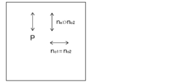
- FIG. FIG. 6 is a schematic diagram showing the relationship of the refractive indices in the P-polarized reflective film when the windshield glass of FIG. 5 is viewed from the front.
- the term "-" is used to include the numerical values before and after it as lower and upper limits.
- the range of ⁇ 1 is a range including numerical value ⁇ 1 and numerical value ⁇ 1, and represented by mathematical symbols ⁇ 1 ⁇ 1 ⁇ 1.
- the "angle” represented by a specific numerical value such as 60° the terms “parallel” and “perpendicular” are generally used in the technical field of the present invention unless otherwise specified.
- Including the allowable margin of error For example, it means that it is within a range of less than ⁇ 10° of the exact angle, and the error from the exact angle is preferably 7° or less, more preferably 5° or less.
- the term "sense" for circularly polarized light means whether it is right-handed circularly polarized light or left-handed circularly polarized light.
- the sense of circular polarization is right circular polarization if the tip of the electric field vector rotates clockwise as time increases, and left if it rotates counterclockwise when viewed as if the light were traveling toward you. Defined as being circularly polarized.
- the term "sense” is sometimes used for the twist direction of the cholesteric liquid crystal spiral.
- the helix direction (sense) of the cholesteric liquid crystal is right, it reflects right-handed circularly polarized light and transmits left-handed circularly polarized light.
- the sense is left, it reflects left-handed circularly polarized light and transmits right-handed circularly polarized light.
- the term "light” means visible light and natural light (non-polarized light) unless otherwise specified.
- Visible light is the wavelength of electromagnetic waves visible to the human eye, and means light in the wavelength range of 380 to 780 nm.
- Invisible light is light in the wavelength range below 380 nm or in the wavelength range above 780 nm.
- B light blue light
- G light green light
- R light red light
- infrared ray indicates a wavelength range of more than 780 nm and less than or equal to 2000 nm among non-visible light.
- the "visible light transmittance” is the A light source visible light transmittance defined in JIS (Japanese Industrial Standards) R 3212:2015 (automobile safety glass test method). That is, with a spectrophotometer using A light source, the transmittance of each wavelength in the wavelength range of 380 to 780 nm is measured, and obtained from the wavelength distribution and wavelength interval of the CIE (International Commission on Illumination) light adaptation standard relative luminosity It is the transmittance obtained by multiplying the transmittance at each wavelength by the weighting factor obtained and taking a weighted average. Further, when simply referring to "reflected light” or “transmitted light", it is used in the sense of including scattered light and diffracted light.
- JIS Japanese Industrial Standards
- R 3212:2015 automobile safety glass test method
- p-polarized light denoted by using a small letter p means polarized light that oscillates in a direction parallel to the plane of incidence of light.
- the plane of incidence means the plane that is perpendicular to the reflective surface (such as the surface of the windshield glass) and contains the incident and reflected rays.
- s-polarized light denoted by using a small letter s means polarized light that oscillates in a direction perpendicular to the plane of incidence of light.
- the plane of oscillation of the electric field vector is perpendicular to the plane of incidence.
- P-polarized light written with a capital letter P is linearly polarized light, and the ratio of p-polarized light to s-polarized light and p-polarized light constituting reflected light is A polarization that is greater than 50% is meant.
- the ratio of p-polarized light to s-polarized light and p-polarized light constituting the reflected light is preferably 60% or more, more preferably 80% or more, and even more preferably 90% or more.
- the ratio of p-polarized light to s-polarized light and p-polarized light constituting the reflected light is not limited, and is preferably 100% or less.
- S-polarized light denoted with a capital letter S is linearly polarized light, and the ratio of s-polarized light to s-polarized light and p-polarized light constituting reflected light exceeds 50%. means some polarization.
- the ratio of s-polarized light to s-polarized light and p-polarized light constituting the reflected light is preferably 60% or more, more preferably 80% or more, and even more preferably 90% or more.
- the ratio of s-polarized light to s-polarized light and p-polarized light constituting the reflected light is not limited, and is preferably 100% or less.
- an optical element with positive optical power means an element that satisfies 1/f>0 where f is the focal length, and includes optical elements that collect light such as concave mirrors and convex lenses.
- a concave mirror collects reflected light
- a convex lens collects transmitted light.
- a diffractive reflective element with positive optical power means an optical element with positive optical power that has a diffractive reflection function.
- an optical element with negative optical power means an element that satisfies 1/f ⁇ 0 where f is the focal length, and includes optical elements that diverge light, such as convex mirrors and concave lenses.
- a convex mirror diverges reflected light and a concave lens diverges transmitted light.
- a transmissive optical element having a negative optical power means an optical element having a light transmitting function among optical elements having a negative optical power.
- the front retardation is a value measured using AxoScan manufactured by Axometrics.
- the measurement wavelength is 550 nm.
- the front retardation can also be measured by KOBRA21ADH or WR (manufactured by Oji Keisoku Kiki Co., Ltd.) by allowing light of a wavelength within the visible light wavelength range to enter in the normal direction of the film.
- the wavelength selection filter can be manually replaced, or the measured value can be converted by a program or the like for measurement.
- the birefringence ( ⁇ n) of the liquid crystal compound is described in "Liquid Crystals/Fundamentals (edited by Koji Okano and Shunsuke Kobayashi)", p. It is a value measured according to the method described in 214. Specifically, ⁇ n at 60° C. can be obtained by injecting a liquid crystal compound into a wedge-shaped cell, irradiating the cell with light having a wavelength of 550 nm, and measuring the refraction angle of the transmitted light.
- the optical isotropy in the "optically isotropic layer” means not exhibiting birefringence.
- the optical anisotropy in the "optically anisotropic layer” means exhibiting birefringence .
- the refractive index n o2 in the direction perpendicular to the in-plane slow axis direction (the in-plane fast axis direction) have a relationship of n e1 >n o2 .
- projection image means an image based on the projection of light from the image display device used.
- the projected image is viewed by the observer as a virtual image that appears to emerge beyond the projection portion of the windshield glass.
- screen image means an image displayed on a drawing device of a virtual image display device or an image drawn on an intermediate image screen or the like by a drawing device.
- An image is a real image as opposed to a virtual image. Both the image and the projected image may be a monochromatic image, a multicolor image with two or more colors, or a full color image.
- liquid crystal compound is used to include those that no longer exhibit liquid crystallinity due to a curing reaction or the like.
- the virtual image display device and HUD system of the present invention are typically used by being mounted on vehicles such as automobiles and trains, airplanes, and transport machines such as ships.
- the HUD system of the present invention is a HUD system comprising a windshield glass having a first glass plate, a P-polarized reflective film and a second glass plate, and the virtual image display device of the present invention.
- a virtual image display device is a virtual image display device configured to be mounted on a transport aircraft and configured so that P-polarized image display light is incident on a projection unit, An image display device for emitting projection image light is provided, and diffractive reflection elements having positive optical power (hereinafter simply referred to as " and a half-wave plate with a front retardation of 200 nm to 400 nm (hereinafter also simply referred to as a "half-wave plate").
- the virtual image display device of the present invention has a half-wave plate on the optical path from the positive diffraction reflection element to the projection unit, so that projected image light from the image display device is positively diffracted.
- the incident light When incident on the reflective element, the incident light is converted to S-polarized light with excellent diffraction efficiency in the positive diffractive reflective element, and the polarized state of the diffracted and reflected light from the positive diffractive reflective element is changed to 1/2 wavelength.
- the light can be changed from S-polarized light to P-polarized light by a plate, and converted to P-polarized light when incident on the projection unit.
- the vibration plane of the p-polarized electric field vector is perpendicular to the diffraction pattern of the positive diffractive reflective element, so that depending on the angle of incidence, Since the pitch interval in the diffraction pattern changes, the diffraction efficiency deteriorates.
- the oscillation plane of the s-polarized electric field vector is parallel to the diffraction pattern of the positive diffraction reflector, the pitch interval in the diffraction pattern hardly changes with the incident angle, and even if the incident angle changes, the output angle does not deviate from the design value and exhibits excellent diffraction efficiency.
- the HUD system of the present invention which includes the virtual image display device of the present invention in combination with the windshield glass having the P-polarized reflective film, has a configuration in which light loss in the optical path for guiding projected image light is suppressed, as described above. Therefore, the brightness of the virtual image display is improved, and the virtual image can be visually recognized even when wearing polarized sunglasses.
- the virtual image display device of the present invention is configured to be mounted on a transport aircraft, and is configured so that P-polarized image display light is incident on the projection unit.
- the P-polarized image display light is incident on the windshield glass of the vehicle, which is the projection unit, by being housed in the instrument panel or dashboard of the vehicle. are arranged and configured in such a way that
- FIGS. 1-3 show an example of the HUD system of the present invention.
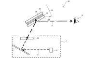
- a virtual image display device 1 shown in FIG. 1 includes an image display device 2, a positive diffraction reflection element 3, and a half-wave plate 5A.
- the virtual image display device 1 shown in FIG. It has a configuration in which half-wave plates 5A are arranged in this order.
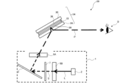
- the virtual image display device 1 shown in FIG. 2 has a configuration in which a half-wave plate 5B is arranged between the image display device 2 and the positive diffraction reflection element 3 on the optical path shown in the virtual image display device 1 shown in FIG. have. That is, in the virtual image display device 1 shown in FIG. 2, the image display device 2, the half-wave plate 5B, positive diffractive reflecting element 3 and half-wave plate 5A are arranged in this order.
- the 3 has a negative transmissive optical element 7 arranged between the half-wave plate 5B and the positive diffraction reflection element 3 on the optical path shown in the virtual image display device 1 shown in FIG. It has a configuration that That is, in the virtual image display device 1 shown in FIG. 3, the image display device 2, the half-wave plate 5B, a negative transmissive optical element 7, a positive diffractive reflective element 3 and a half-wave plate 5A are arranged in this order. 1 to 3, S indicates S-polarized light, P indicates P-polarized light, and L in FIGS. 2 and 3 indicates linearly polarized light. Represents the type of polarization.
- the windshield glass 24 shown in FIGS. 1-3 comprises a first glass plate 30, a P-polarized reflective film 10, and a second glass plate 28 in this order.
- the windshield glass 24 is arranged with respect to the virtual image display device 1 so that the P-polarized image display light from the virtual image display device 1 is incident on the second glass plate 28 side.
- An observer D observes the image projected on the windshield glass 24, which is the projection section, as a virtual image through the windshield glass 24 by reflecting the polarized light.
- the virtual image display device 1 and the windshield glass 24 will be described in order below.
- the virtual image display device 1 includes an image display device 2, a positive diffractive reflection element 3, and a half-wave plate 5A for projecting image light emitted from the image display device 2. They are arranged in this order on the optical path leading to the windshield glass 24 which is the projection section.
- the positive diffraction reflection element 3 is not particularly limited as long as it is an optical element that diffracts and reflects the projection image light emitted from the image display device 2, and is a commonly used positive diffraction reflection element. element can be used.
- the virtual image display device 1 of the present invention on the optical path that guides the projected image light emitted from the image display device 2 to the windshield glass 24 that is the projection unit, from the image display device 2 side,
- the positive diffraction reflection element 3 By having the positive diffraction reflection element 3, the half-wave plate 5A, and the windshield glass 24 as the projection section, the light diffracted and reflected by the positive diffraction reflection element 3 is converted into S-polarized light with excellent diffraction efficiency
- the /2 wavelength plate 5A converts the S-polarized light into the P-polarized light, and the efficiently reflected P-polarized light is made incident on the P-polarized light reflecting film 10 on the windshield glass 24.
- the positive diffractive reflective element 3 for example, a reflective hologram element having a refractive index distribution in which a photosensitive material is fixed (hereinafter also simply referred to as a "positive reflective hologram element”), an alignment film and a liquid crystal layer.
- a diffraction element having a liquid crystal alignment pattern corresponding to the periodic pattern of the alignment film and having a function of diffracting and reflecting incident light hereinafter also simply referred to as a "positive reflection type liquid crystal diffraction element”). is mentioned.
- a positive reflection hologram element has a refractive index distribution in which a high refractive index and a low refractive index are periodically distributed, and functions as a positive diffraction reflection element.
- a positive reflection hologram element for example, as described in FIG. can be a volume-type hologram element formed in the A periodic refractive index distribution in the hologram layer functions as a diffraction structure.
- the pair of light-transmitting substrate layers are made of, for example, synthetic resin or glass in the form of light-transmitting thin plates to protect and reinforce the hologram layer.
- the hologram layer is formed in advance in a hologram material with amplitude and phase information of the object light recorded as interference fringes with the reference light.
- the interference fringes referred to here are interference fringes embodied by the periodic refractive index distribution described above.
- materials that can record information on the amplitude and phase of object light through spatial modulation of the refractive index such as synthetic resin-based materials, gelatin photosensitive materials, and silver halide photosensitive materials, are selectively adopted. can be
- the hologram layer of the positive reflection hologram element is formed with interference fringes that cause the display light to be diffracted and reflected while being condensed. For this diffraction, first-order diffracted light, which has the highest diffraction efficiency, is mainly used.
- a positive reflection hologram element does not have a polarization characteristic in the reflected light and performs non-polarization reflection.
- a positive reflection hologram element that achieves positive optical power using first-order diffracted light achieves chromatic dispersion in the direction opposite to that of a convex refractive lens that exhibits normal dispersion for visible light. That is, the magnitude of the deflection angle due to diffraction by the positive reflection hologram element works so that the long wavelength side light beam is larger than the short wavelength side light beam.
- a positive reflection hologram element can be produced by a conventional method.
- a laser beam is split into two by a beam splitter, and the amplitude and phase information of the object beam is obtained by using the separated two laser beams to obtain the interference pattern (periodic A volume-type reflection hologram element can be produced by forming a refractive index distribution) and curing the photosensitive material when the refractive index distribution is formed.
- the irradiation direction and/or irradiation surface of the laser beam is adjusted according to the size of the windshield glass, the distance between the windshield glass and the virtual image display device, other optical members, etc., so as to obtain a hologram element that exhibits the desired diffraction reflection. Adjustments can be made to produce the desired interference pattern.
- a positive reflective liquid crystal diffraction element has an alignment film and a liquid crystal layer, has a liquid crystal alignment pattern corresponding to the periodic pattern of the alignment film, and has a function of diffracting and reflecting incident light.
- the optical element described in WO 2019/131966 has a small wavelength dependence of the reflection angle, and can reflect red light, green light, and blue light incident from the same direction in almost the same direction. It can be preferably used as the positive reflection type liquid crystal diffraction element.
- the positive reflection type liquid crystal diffraction element has a polarization characteristic in the reflected light, which is circularly polarized light reflection.
- a 1/4 wavelength plate is pasted on the positive reflective liquid crystal diffraction element, and the projection image from the image display device 2 is placed on the 1/4 wavelength plate side. It is used as a positive diffractive reflection element that reflects linearly polarized light by arranging it so that light is incident thereon.
- a positive reflective liquid crystal diffraction element can be produced by a conventional method. For example, an alignment film is formed on an undercoat layer formed on a support, the alignment film is irradiated with a laser beam, and the interference pattern (surface periodic structure) is controlled by changing the crossing angle of the two laser beams.
- a reflective liquid crystal diffraction element can be produced by forming a cholesteric liquid crystal layer on the photo-alignment film obtained by curing. For example, reference can be made to the method for producing an optical element described in WO2019/131966.
- the half-wave plate 5A is a projection unit for projecting image light emitted from the image display device 2. It is provided so as to be positioned between the positive diffractive reflection element 3 and the windshield glass 24 which is the projection portion on the optical path leading to the windshield glass 24 . Further, as shown in FIGS. 2 and 3, the virtual image display device 1 of the present invention includes a 1/2 wave plate 5A and a 1/2 wavelength plate between the positive diffraction reflection element 3 and the image display device 2 on the optical path. A /2 wavelength plate 5B may be further provided.
- Both of the above half-wave plates 5A and 5B are not particularly limited as long as they are half-wave plates having a front retardation of 200 nm to 400 nm at a wavelength of 550 nm measured by the method described above, depending on the purpose. It can be used as appropriate.
- the projection image light emitted from the image display device 2 is projected onto the positive diffraction reflection element 3 on the optical path for guiding the projection image light to the windshield glass 24 which is the projection section.
- the S-polarized light diffracted and reflected with good diffraction efficiency by the positive diffraction reflective element 3 is transferred to the P-polarized reflective film 10 on the windshield glass 24. It can be converted into P-polarized light that is efficiently reflected. Also, as shown in FIGS.
- the virtual image display device 1 of the present invention has a half-wave plate 5B between the positive diffraction reflection element 3 and the image display device 2 on the optical path, , the projected image light emitted from the image display device 2 can be converted into S-polarized light that is diffracted and reflected by the positive diffraction reflecting element 3 with high diffraction efficiency. Therefore, the optical loss in the optical path for guiding the projection image light is further suppressed, and the brightness of the virtual image display and the visibility when wearing polarized sunglasses can be further improved.
- a stretched polycarbonate film for example, a stretched polycarbonate film, a stretched norbornene-based polymer film, an oriented transparent film containing inorganic particles having birefringence such as strontium carbonate, and a support
- examples include a thin film on which an inorganic dielectric is obliquely deposited, a film in which a polymerizable liquid crystal compound is uniaxially oriented and fixed in orientation, and a film in which a liquid crystal compound is uniaxially oriented and orientation is fixed.
- films in which a polymerizable liquid crystal compound is uniaxially oriented and oriented and fixed are preferably exemplified as the half-wave plates 5A and 5B.
- Such half-wave plates 5A and 5B are produced, for example, by coating a liquid crystal composition containing a polymerizable liquid crystal compound on the surface of a transparent substrate, a temporary support, or an alignment layer, and then polymerizing the liquid crystal composition. It is possible to form a nematic liquid crystal compound in a liquid crystal state and then fix it by curing.
- the formation of the half-wave plates 5A and 5B in this case can be carried out in the same manner as the formation of the cholesteric liquid crystal layer, which will be described later, except that the chiral agent is not added to the liquid crystal composition.
- the heating temperature is preferably 50 to 120.degree. C., more preferably 60 to 100.degree.
- the half-wave plates 5A and 5B are formed by coating a composition containing a polymer liquid crystal compound on the surface of a transparent substrate, a temporary support, an alignment layer, or the like, forming a nematic alignment in a liquid crystal state, and then cooling. It may be a layer obtained by fixing this orientation by.
- the half-wave plates 5A and 5B may be formed by laminating two quarter-wave plates using a highly transparent adhesive transfer tape (OCA tape).
- OCA tape highly transparent adhesive transfer tape
- the quarter-wave plate is not particularly limited as long as the half-wave plates 5A and 5B can be obtained.
- a quarter-wave plate having a front retardation of 100 nm to 200 nm is preferable.
- the thickness of the half-wave plates 5A and 5B is not limited, it is preferably 0.2-300 ⁇ m, more preferably 0.5-150 ⁇ m, and even more preferably 1.0-80 ⁇ m.
- the thickness of the half-wave plates 5A and 5B formed from the liquid crystal composition is not particularly limited, but is preferably 0.2 to 10 ⁇ m, more preferably 0.5 to 5.0 ⁇ m, and more preferably 0.7 ⁇ m. ⁇ 2.0 ⁇ m is more preferred.
- the half-wave plates 5A and 5B are incorporated into the HUD system 20, the half-wave plates 5A and 5B are rotated so that the transmitted light is polarized as desired. Orient and place. Specifically, as shown in FIGS. 1 to 3, the half-wave plate 5A is arranged so that the transmitted light, that is, the light incident on the windshield glass 24 is P-polarized. On the other hand, as shown in FIGS. 2 and 3, the half-wave plate 5B is arranged so that the transmitted light, that is, the light incident on the positive diffraction reflecting element 3 is S-polarized light. In the virtual image display device 1 shown in FIG.
- the S-polarized light that is transmitted through the half-wave plate 5B is directly incident on the positive diffraction reflection element 3, and in the virtual image display device 1 shown in FIG.
- the S-polarized light transmitted from the two-wave plate 5B is transmitted through the negative transmissive optical element 7 as S-polarized light, and the S-polarized light is incident on the positive diffraction reflection element 3 .
- the P-polarized reflective film 10 has a layer made of cholesteric liquid crystal (also referred to as a "cholesteric liquid crystal layer")
- the positive diffractive reflective element 3 is a positive reflective liquid crystal diffractive element
- the directions of the slow axes of the half-wave plates 5A and 5B can be set, for example, by rubbing the underlying alignment film when the half-wave plates 5A and 5B are cholesteric liquid crystal layers.
- Negative transmission type optical element In the virtual image display device of the present invention, a transmission type optical element having a negative optical power (simply referred to as “negative transmission (also referred to as “type optical element").
- negative transmission also referred to as “type optical element”
- the positive diffractive reflective element condenses light and diffuses the light.
- Combination with a negative transmissive optical element can improve chromatic aberration, which is preferable. That is, since the direction of the color shift caused by the difference in deflection angle due to diffraction is opposite between the positive diffractive reflective element and the negative transmissive optical element, the value shown in Equation 1 below is set to 0.
- the virtual image display device of the present invention has a negative transmissive optical element, as long as it is arranged between the positive diffraction reflective element and the image display device on the optical path for guiding the projected image light to the projection unit.
- transmissive optical elements 7 can be arranged.
- the negative diffraction element is positioned between the image display device 2 and the positive diffraction reflection element 3 and between the image display device 2 and the half-wave plate 5B.
- a configuration in which a transmissive optical element 7 is arranged may be employed.
- a configuration may be adopted in which a negative transmissive optical element 7 is arranged between the image display device 2 and the positive diffraction reflection element 3 . From the viewpoint of further improving diffraction efficiency, as shown in FIG. is preferred.
- the negative transmissive optical element 7 is not particularly limited as long as it has negative optical power and transmits the projection image light emitted from the image display device 2, and may be a commonly used negative transmissive optical element.
- Optical elements can be used.
- a negative transmission hologram element has a refractive index distribution in which a high refractive index and a low refractive index are periodically distributed, and functions as a negative diffraction transmission element.
- the negative transmission hologram element the above-described positive reflection hologram element is used except that the optical power is adjusted to be negative (1/f ⁇ 0) instead of positive (1/f>0). can be applied.
- the above-described description of the method of fabricating the positive reflection hologram element is applied, except that the optical power is adjusted to be negative instead of positive. can be done.
- the hologram layer of the negative transmissive hologram element is formed with interference fringes that allow the display light to pass therethrough and diverge the display light by diffraction.
- first-order diffracted light which has the highest diffraction efficiency, is mainly used.
- a negative transmission hologram element that achieves negative optical power using first-order diffracted light achieves chromatic dispersion in the opposite direction to a concave refractive lens that exhibits normal dispersion for visible light.
- the magnitude of the deflection angle due to diffraction by the negative transmission hologram element works so that the long-wavelength ray is larger than the short-wavelength ray.
- a negative transmission type liquid crystal diffraction element has an alignment film and a liquid crystal layer, has a liquid crystal alignment pattern corresponding to the periodic pattern of the alignment film, and has a function of diffracting and transmitting incident light. It is not particularly limited.
- the negative transmissive liquid crystal diffraction element in the positive reflection type liquid crystal diffraction element described above, the chiral agent is not added so that the optical power is negative rather than positive, and the liquid crystal layer is not cholesterically aligned.
- the above description of the positive reflective liquid crystal diffraction element can be applied.
- the above-described method for manufacturing the positive reflective liquid crystal diffraction element is the same except that the chiral agent is not added to prevent cholesteric alignment when forming the liquid crystal layer.
- the description relating to the fabrication of positive reflective liquid crystal diffraction elements can be applied.
- the crossing angle of the laser light can be adjusted according to the size of the windshield glass, the distance between the windshield glass and the virtual image display device, other optical members, etc. so as to obtain a negative transmissive liquid crystal diffraction element exhibiting desired characteristics. can be adjusted to be smaller at the center of the element and larger at the edge of the element.
- the negative transmission type refractive lens is made of, for example, a synthetic resin or glass exhibiting normal dispersion for visible light so as to have translucency. It is a lens that transmits light while refracting it on its surface.
- a negative transmissive refractive lens has a negative optical power and is a concave lens that diverges display light by refraction.
- a biconcave lens, a plano-concave lens, or a concave meniscus lens can be employed as a negative transmissive refractive lens that is a concave lens.
- the negative transmissive refracting lens is adjusted to exhibit the desired optical characteristics according to the size of the windshield glass, the distance between the windshield glass and the virtual image display device, other optical members, etc., and is manufactured by a conventional method. be able to.
- the image display device 1 is an image display device that emits projection image light (hereinafter also referred to as “projection light”), and includes a “device for projecting a drawn image” to display an image. It emits projection light carrying a .
- the projected image light emitted from the image display device 1 may be S-polarized light incident on the positive diffraction reflection element 3, and is preferably linearly polarized light.
- the projection image light emitted from the image display device 2 is preferably S-polarized light.
- the projection image light emitted from the image display device 2 has S Any linearly polarized light may be used as long as it is polarized light.
- S-polarized light not only S-polarized light, but also an image display device that emits linearly polarized light whose azimuth angle is rotated from 0° to about 10° with respect to S-polarized light as projection light can be preferably used.
- the azimuth angle means the angle by which the vibration axis is rotated in the plane containing the vibration axes of S-polarized light and P-polarized light.
- linearly polarized light whose azimuth angle is rotated by about 10° over 0° with respect to S-polarized light means linearly polarized light having an oscillation axis rotated by ⁇ 10° to 10° from the oscillation axis of S-polarized light.
- the image display device 2 may be arranged so that S-polarized light is incident on the positive diffraction reflection element 3 .
- the image display device 2 preferably includes a rendering device and reflects and displays an image (real image) rendered on a small intermediate image screen as a virtual image by a combiner.
- a commonly-used image display device used in a HUD system can be used as long as it can emit linearly polarized projection light.
- the imaging distance of the virtual image that is, the imaging position of the virtual image is variable.
- Methods for changing the imaging distance of a virtual image in a virtual image display device include, for example, a method of moving an image generation surface (screen) (see Japanese Patent Application Laid-Open No. 2017-21302), and switching between a plurality of optical paths having different optical path lengths. (see WO2015/190157), a method of changing the optical path length by inserting and/or moving a mirror, a method of changing the focal length using a combination lens as an imaging lens, a method of moving the image display device, a virtual image and a method of using a variable focus lens (see WO2010/116912).
- the virtual image display device may be one in which the imaging distance of the virtual image can be continuously changed, or one in which the imaging distance of the virtual image can be switched at two or three or more points.
- a light field display can also be used as the image display device 2 in the virtual image display device 1 of the present invention.
- a light field display means an image display device having light-emitting pixels and microlenses, with the microlenses formed on the light-emitting pixels.
- light field displays can display multifocal and/or 3D images because the focal point of each luminescent pixel can be changed, whereas the pixels used for image display can be unifocal images.
- the virtual image display device of the present invention the light loss in the optical path for guiding the projected image light is suppressed. It is possible to improve the brightness of the display and the visibility when wearing polarized sunglasses.
- a commonly used light field display can be used without particular limitation, and for example, the light field display described in JP-A-2020-160296 can be mentioned.
- a rendering device may itself be a device that displays an image, or it may be a device that emits light capable of rendering an image.
- the light from the light source may be adjusted by a drawing method such as an optical modulator, laser luminance modulation means, or light deflection means for drawing.
- a drawing device means a device that includes a light source and, depending on the drawing method, an optical modulator, a laser luminance modulation means, or an optical deflection means for drawing.
- the light source that constitutes the image display device 2 is not particularly limited, and LEDs (light emitting diodes), organic light emitting diodes (OLEDs), discharge tubes, laser light sources, and the like are used in image display devices, drawing devices, displays, and the like. Common light sources are available. Among these, LEDs and discharge tubes are preferable because they are suitable as light sources for drawing devices that emit linearly polarized light, and LEDs are particularly preferable. This is because the emission wavelengths of LEDs are not continuous in the visible light region, and thus are suitable for combination with a combiner using a cholesteric liquid crystal layer that exhibits selective reflection in a specific wavelength region, as will be described later.
- the drawing method can be selected according to the laser light source, and is not particularly limited. Examples of drawing methods include a method using a fluorescent display tube, a liquid crystal LCD (Liquid Crystal Display) method and a LCOS (Liquid Crystal on Silicon) method using liquid crystal, a DLP (registered trademark) (Digital Light Processing) method, and For example, a scanning method using a laser can be used.
- the drawing method may be a method using a vacuum fluorescent display integrated with a light source. As a drawing method, the LCD method is preferable.
- the DLP system is a display system using a DMD (Digital Micromirror Device), and images are drawn by arranging micromirrors for the number of pixels, and light is emitted from a projection lens.
- DMD Digital Micromirror Device
- the scanning method is a method in which a light beam is scanned on a screen and an image is formed using an afterimage of the eye.
- brightness-modulated laser beams of, for example, red, green, and blue colors are bundled into a single beam by a combining optical system, a condenser lens, or the like, and the beam is converted into light. It is sufficient that the image is scanned by the deflection means and drawn on an intermediate image screen, which will be described later.
- the luminance modulation of each color laser light such as red light, green light, and blue light may be performed directly as intensity change of the light source, or may be performed by an external modulator.
- Examples of the light deflection means include a galvanomirror, a combination of a galvanomirror and a polygon mirror, and MEMS (Micro Electro Mechanical Systems), among which MEMS is preferred.
- Scanning methods include a random scan method, a raster scan method, and the like, and it is preferable to use the raster scan method.
- the laser light can be driven, for example, with a resonant frequency in the horizontal direction and a sawtooth wave in the vertical direction. Since the scanning method does not require a projection lens, it is easy to reduce the size of the device.
- the output light from the drawing device may be adjusted so that S-polarized light is incident on the positive diffraction reflection element 3, and linearly polarized light is preferable.
- a drawing device using an LCD or LCOS drawing method and a drawing device using a laser light source essentially emit linearly polarized light.
- the polarization directions (transmission axis directions) of the light of the plurality of wavelengths are preferably the same.
- the rendering device may use an intermediate image screen.
- An "intermediate image screen” is a screen on which an image is drawn. That is, when the light emitted from the rendering device is not yet visible as an image, the rendering device forms a visible image on the intermediate image screen with this light.
- the image rendered on the intermediate image screen may be projected onto the combiner by light transmitted through the intermediate image screen, or may be reflected onto the intermediate image screen and projected onto the combiner.
- intermediate image screens include scattering films, microlens arrays, and screens for rear projection.
- the intermediate image screen if the intermediate image screen has birefringence, the plane of polarization and the light intensity of the polarized light incident on the intermediate image screen are disturbed, and in the combiner (P-polarized reflective film 10), Color unevenness and the like are likely to occur, but this problem of color unevenness can be reduced by using a retardation film having a predetermined retardation.
- the intermediate image screen preferably has the function of spreading and transmitting the incident light. This is because the projected image can be enlarged and displayed.
- Such intermediate image screens include, for example, screens composed of microlens arrays.
- Microarray lenses used in HUD systems are described, for example, in JP-A-2012-226303, JP-A-2010-145745, and JP-T-2007-523369.
- the projector may include a reflecting mirror or the like that adjusts the optical path of the projection light formed by the drawing device.
- HUD systems using windshield glass as a reflective film are disclosed in JP-A-2-141720, JP-A-10-96874, JP-A-2003-98470, US Pat. 2006-512622 and the like can be referred to.
- Windshield glass is particularly useful for HUD systems used in combination with image display devices that use lasers, LEDs, OLEDs (organic light emitting diodes), etc., whose emission wavelengths are not continuous in the visible light region, as light sources. This is because the central wavelength of selective reflection of the cholesteric liquid crystal layer can be adjusted according to each emission wavelength. It can also be used for projection on displays such as LCDs (liquid crystal display devices) in which the display light is polarized.
- LCDs liquid crystal display devices
- the incident light from the virtual image display device 1 of the present invention to the windshield glass 24 is preferably incident at an oblique incident angle of 45° to 70° with respect to the normal line of the P-polarized reflective film 10 .
- the Brewster angle at the interface between glass with a refractive index of about 1.51 and air with a refractive index of 1 is about 56°.
- the amount of reflected light from the surface of the windshield glass 24 on the viewing side is less than that of the selective reflection layer of the P-polarized reflective film 10, and image display with little influence of double images is possible. It is also preferred that said angle is between 50° and 65°.
- the projected image is observed on the incident side of the projected light at an angle of 45° to 70°, preferably 50° to 65° on the side opposite to the incident light with respect to the normal to the selective reflection layer of the P-polarized reflective film 10 .
- Any configuration can be used as long as it can be performed at an angle of .
- the incident light may enter from any direction, such as the top, bottom, left, or right of the windshield glass 24, and may be determined in correspondence with the viewing direction. For example, a configuration in which light is incident at an oblique incident angle as described above from the downward direction during use is preferable.
- the P-polarized reflective film 10 in the windshield glass 24 is arranged to reflect incident p-polarized light.
- the image display light (projection light) emitted from the virtual image display device 1 of the present invention and incident on the projection section is P-polarized light.
- the polarization directions are adjusted selectively for all colors. It is preferable to make the light incident as P-polarized light in the wavelength range.
- the HUD system 20 may be a projection system with variable virtual image formation positions.
- the virtual image formation position is a position where the driver of the vehicle can visually recognize the virtual image, for example, a position 1000 mm or more beyond the windshield glass as viewed from the driver.
- the vertical direction Y of the windshield glass 24 means the longitudinal direction of the windshield glass 24 on the paper. It is a direction corresponding to the vertical direction of a vehicle or the like in which the windshield glass 24 is arranged, and is defined with the ground side as the lower side and the opposite side as the upper side.
- the windshield glass 24 may be arranged at an angle for reasons of structure or design. direction.
- the surface is the exterior side of the vehicle.
- the virtual image display device 1 emits P-polarized projection light to the second glass plate 28 in the windshield glass 24 .
- the virtual image display device 1 By making the projection light emitted to the windshield glass 24 by the virtual image display device 1 P-polarized light, the reflection of the projection light from the first glass plate 30 and the second glass plate 28 of the windshield glass 24 is greatly reduced. Therefore, it is possible to suppress inconveniences such as the observation of double images.
- the virtual image display device 1 emits the P-polarized projection light to the windshield glass 24 at Brewster's angle. This eliminates the reflection of the projection light on the first glass plate 30 and the second glass plate 28, making it possible to display a clearer image.
- the windshield glass 24 is windshield glass having a first glass plate 30, a P-polarized reflective film 10, and a second glass plate 28 in this order.
- Windshield glass means window glass and windshield glass for vehicles such as cars and trains, airplanes, ships, motorcycles, and vehicles in general such as playground equipment.
- the windshield glass is preferably used as a windshield, a windshield, etc. in front of the traveling direction of the vehicle.
- the windshield glass 24A shown in FIG. 4 has a second glass plate 28, a heat seal layer 38, a P-polarized reflective film 10A, an intermediate film 36, and a first glass plate 30 in this order.
- the P-polarized reflective film 10A is arranged so that the polarization conversion layer 14 is on the first glass plate 30 side and the retardation layer 16 (transparent substrate 18) is on the second glass plate 28 side.
- the windshield glass 24B shown in FIG. 5 has a second glass plate 28, an intermediate film 36, a P-polarized reflective film 10B, an intermediate film 36, and a first glass plate 30 in this order.
- the second glass plate 28 and the first glass plate 30 When the windshield glass is used in a vehicle, curved glass is often used as the second glass plate 28 and the first glass plate 30 . In that case, if the second glass plate 28 is on the inside of the vehicle and the first glass plate 30 is on the outside of the vehicle, the second glass plate 28 is arranged with the convex side facing the first glass plate 30, and the first The second glass plate 30 is arranged with the concave side facing the second glass plate 28 .
- the second glass plate 28 and the first glass plate 30 are curved glasses, the example shown in FIG.
- the conversion layer 14 and the selective reflection layer 11 are arranged in this order.
- the retardation layer 16 is arranged between the selective reflection layer 11 and the second glass plate 28 .
- the visible light transmittance of the windshield glass is preferably 70% or more, more preferably over 70%, still more preferably 75% or more, and particularly preferably 80% or more, from the viewpoint of legal regulations.
- the above-mentioned visible light transmittance is preferably satisfied at any position of the windshield glass, and it is particularly preferable that the above-mentioned visible light transmittance is satisfied at the position where the P-polarized reflective film exists. .
- the P-polarized reflective film can increase the visible light transmittance, and the above visible light transmittance is satisfied even when any of the glasses commonly used for windshield glass is used. can be configured.
- the windshield glass may be, for example, planar or three-dimensional with a curved surface such as a concave surface or a convex surface.
- the viewing side such as the upward direction in normal use, the viewer side, the driver side, and the inside of the vehicle.
- the P-polarized reflective film may be provided on the projected image display portion (projected image reflection portion) of the windshield glass.
- the windshield glass 24 used in the HUD system 20 of the present invention is a laminated glass structure, and the P-polarized reflective film 10 is composed of two sheets of glass (a first glass plate 30 and a second glass plate 28) that make up the laminated glass. ) is protected by placing it between
- the windshield glass 24 having a configuration in which the P-polarized reflective film 10 is provided on the outer surface of the laminated glass that constitutes the windshield glass may also be used. It may be provided on the incident side of the lens) or on the outside, but it is preferably provided on the inside.
- the P-polarized reflective film 10 is a member for displaying a projected image by reflecting the projected image. Therefore, the P-polarized reflective film 10 may be provided at a position where the projected image projected from the virtual image display device 1 can be visually displayed. That is, in the HUD system 20 of the present invention, the P-polarized reflective film 10 functions as a combiner for the HUD system.
- the combiner can visually display the image projected from the virtual image display device, and when the combiner is observed from the incident surface side of the projected image, the incident surface of the projection light such as the scenery is different from the incident surface. It means an optical member that can simultaneously observe information on the opposite surface side. That is, the combiner has a function as an optical path combiner that superimposes external light and projected image light for display.
- the P-polarized reflective film may be provided on the entire surface of the windshield glass, or may be provided on a part of the windshield glass in the plane direction, but it is preferably provided on a part of the windshield glass.
- the P-polarized reflective film may be provided at any position on the windshield glass. It is preferable that the virtual image is provided at an easily accessible position.
- the position of the P-polarized reflective film on the windshield glass may be determined based on the relationship between the position of the driver's seat in the vehicle in which the HUD system is mounted and the position of the virtual image display device.
- the P-polarized reflective film may be planar without curved surfaces, or may have curved surfaces. Also, the P-polarized reflective film may have a concave or convex shape as a whole, and may display a projected image by enlarging or reducing it.
- the P-polarized reflective film means a reflective film having a function of reflecting p-polarized light.
- the P-polarized reflective film 10 has a selective reflection layer having a function of reflecting p-polarized light.
- the windshield glass used in the HUD system of the present invention preferably has a selective reflection layer containing the following three wavelengths of ⁇ B , ⁇ G and ⁇ R as selective reflection center wavelengths at an incident angle of 60°. 400nm ⁇ ⁇ B ⁇ 500nm 500nm ⁇ G ⁇ 600nm 600nm ⁇ R ⁇ 700nm
- the selective reflection central wavelength of the selective reflection layer and the half width of the reflection peak having this selective reflection central wavelength are obtained as follows.
- a spectrophotometer eg, JASCO Corporation, trade name: V-670
- a desired eg, 60 °
- V-670 a desired relative to the normal direction of the selective reflection layer
- a maximum reflectance peak is observed in the selective reflection band.
- the value of the wavelength on the short wavelength side is ⁇ l (nm)
- the value of the wavelength on the long wavelength side is ⁇ l (nm).
- the selective reflection center wavelength obtained as described above is the centroid position of the reflection peak of the circularly polarized reflection spectrum measured at a desired light incident angle with respect to the normal direction of the selective reflection layer when the selective reflection layer is made of a cholesteric liquid crystal. approximately coincides with the wavelength at Further, in the present invention, the natural light reflectance at the selective reflection center wavelength of the selective reflection layer is also determined by the method described in Examples below. It should be noted that the reflection spectrum of the selective reflection layer is measured in the state of the windshield glass including the selective reflection layer, as described later in Examples.
- Examples of the P-polarized reflective film containing the above-described selective reflection layer include a P-polarized reflective film containing a cholesteric liquid crystal layer having a function of reflecting circularly polarized light, and a laminate of an optically anisotropic layer and an optically isotropic layer.
- a P-polarized reflective film including a selective reflective layer (hereinafter also referred to as a "dielectric multilayer film") having a function of reflecting P-polarized light is preferably exemplified.
- the P-polarized reflective film will be described in order based on the P-polarized reflective film 10A in the windshield glass 24A shown in FIG. 4 and the P-polarized reflective film 10B in the windshield glass 24B shown in FIG. Further, the cholesteric liquid crystal layer and the dielectric multilayer film will be explained in the explanation of each P-polarized reflective film.
- FIG. 4 is a schematic diagram showing an example of the windshield glass 24 used in the present invention. , the polarization conversion layer 14, the selective reflection layer 11, the retardation layer 16, and the transparent substrate 18 in this order.
- the retardation layer 16 is incident from the second glass plate 28 side. It converts p-polarized projected light into circularly polarized light.
- the selective reflection layer 11 (cholesteric liquid crystal layer 12 ) selectively reflects this circularly polarized light to re-enter the retardation layer 16 .
- the retardation layer 16 converts circularly polarized light into p-polarized light.
- the P-polarized reflective film 10A thereby reflects the incident p-polarized projection light as the p-polarized light.
- the retardation layer 16 converts the incident p-polarized light into circularly polarized light in the direction of rotation reflected by the selective reflection layer 11. is set to convert to That is, when the selective reflection layer 11 selectively reflects right-handed circularly polarized light, the retardation layer 16 is set to convert incident p-polarized light into right-handed circularly polarized light. Conversely, when the selective reflection layer 11 selectively reflects left-handed circularly polarized light, the retardation layer 16 is set to convert incident p-polarized light into left-handed circularly polarized light.
- the selective reflection layer 11 preferably includes three cholesteric liquid crystal layers (12R, 12G, 12B).
- the three cholesteric liquid crystal layers have different selective reflection center wavelengths at a light incident angle of 60°. and a cholesteric liquid crystal layer 12R having a selective reflection center wavelength ⁇ R at a light incidence angle of 60°, which will be described later.
- it has a cholesteric liquid crystal layer 12R, a cholesteric liquid crystal layer 12G, and a cholesteric liquid crystal layer 12B in this order.
- each cholesteric liquid crystal layer is in direct contact with any other cholesteric liquid crystal layer.
- the central wavelength of selective reflection at a light incident angle of 60° is 300 nm or more and less than 400 nm.
- cholesteric liquid crystal layer UV is also preferable from the viewpoint of suppressing reflected color.
- the cholesteric liquid crystal layer is a layer in which a liquid crystal compound is fixed in the orientation state of the helical structure of the cholesteric liquid crystal phase, and reflects light of the selective reflection center wavelength according to the pitch of the helical structure, and reflects light of other wavelengths. permeates a wide range of light.
- the cholesteric liquid crystal layer exhibits selective reflectivity for either left or right circularly polarized light at a specific wavelength.
- the reflected wavelength and reflectance can be adjusted by the selective reflection center wavelength, thickness (helical pitch number), etc. of the cholesteric liquid crystal layer.
- each cholesteric liquid crystal layer is preferably in direct contact with any other cholesteric liquid crystal layer.
- a cholesteric liquid crystal layer 12R having a selective reflection central wavelength ⁇ R at a light incident angle of 60° and a cholesteric liquid crystal layer 12G having a selective reflection central wavelength ⁇ G at a light incident angle of 60°. are in contact with each other, and a cholesteric liquid crystal layer 12G having a selective reflection central wavelength ⁇ G at a light incident angle of 60° and a cholesteric liquid crystal layer 12B having a selective reflection central wavelength ⁇ B at a light incident angle of 60° in contact with each other.
- the film thickness between the layers becomes thicker, making it difficult to obtain the effect of interference of light reflected by each cholesteric liquid crystal layer.
- the wavelength band width can be narrowed by the effect of interference of light reflected by each cholesteric liquid crystal layer.
- the film thickness of each cholesteric liquid crystal layer is thinner than the wavelength of light (380 nm to 780 nm of visible light), the effect of interference becomes more pronounced.
- each cholesteric liquid crystal layer is not limited to a configuration in which they are in direct contact, and may be configured to be laminated via an adhesive layer or the like.
- each cholesteric liquid crystal layer has at least one selective reflection central wavelength among the three wavelengths ⁇ B , ⁇ G and ⁇ R described above as the selective reflection central wavelength at a light incident angle of 60°.
- at least one layer of the cholesteric liquid crystal layer may have two or more selective reflection center wavelengths.
- a cholesteric liquid crystal layer having two or more selective reflection center wavelengths is achieved by a helical structure in which the helical pitch varies in the thickness direction.
- the selective reflection layer 11 has three layers of cholesteric liquid crystal layers with different selective reflection center wavelengths, but the selective reflection layer 11 is not limited to this. It may have layers, or it may have two or four or more cholesteric liquid crystal layers.
- the total thickness of the selective reflection layer 11 is preferably 0.5 to 30 ⁇ m, more preferably 1 to 15 ⁇ m, from the viewpoint of exhibiting high transmittance while exhibiting sufficient natural light reflectance by the selective reflection layer 11 .
- the selective reflection layer made of a cholesteric liquid crystal layer reflects circularly polarized light. Therefore, the P-polarized reflective film preferably has a layer for converting P-polarized light incident on the P-polarized reflective film into circularly polarized light.
- the layer that converts the polarization state of light includes a polarization conversion layer and a retardation layer.
- the polarization conversion layer exhibits optical rotation and birefringence with respect to visible light, and converts the polarization state of incident light.
- the polarization conversion layer comprises a layer in which a birefringent material such as a liquid crystal compound is oriented with a twist amount of 360° or less.
- the phase difference layer changes the state of incident polarized light by adding a phase difference (optical path difference) to two orthogonal polarized light components.
- the retardation layer is a layer in which birefringent materials such as liquid crystal compounds are aligned in the same direction and does not have optical rotation.
- the P-polarized reflective film By configuring the P-polarized reflective film to have a polarization conversion layer or a retardation layer on the light incident side of the selective reflection layer, the P-polarized light incident on the P-polarized reflective film is converted into circularly polarized light and selected
- the reflective layer may reflect the circularly polarized light
- the polarization conversion layer or the retardation layer may convert the reflected circularly polarized light into P-polarized light and emit the P-polarized light.
- the P-polarized reflective film 10A has the polarization conversion layer 14 on one side of the selective reflection layer 11 and the retardation layer 16 on the other side. Then, the retardation layer 16 is arranged on the side of the second glass plate 28, which is the inside of the vehicle, and the polarization conversion layer 14 is arranged on the side of the first glass plate 30, which is the outside of the vehicle.
- the retardation layer 16 has the function of converting the projected p-polarized light into circularly polarized light reflected by the cholesteric liquid crystal layer of the selective reflection layer 11 .
- the polarization conversion layer 14 has an optical compensation function for light incident from outside the windshield glass. For example, s-polarized light incident from the outside of the windshield glass changes its polarization state when passing through the retardation layer 16, and the p-polarized component is mixed. Since polarized sunglasses cut s-polarized light, this p-polarized component is transmitted through polarized sunglasses.
- the function of the polarized sunglasses to cut the glare of the reflected light, which is mainly composed of s-polarized light, is impaired, which poses a problem that hinders driving.
- a structure having the polarization conversion layer 14 and performing optical compensation with the polarization conversion layer 14 suitability for polarized sunglasses can be improved.
- the polarization conversion layer 14 is on the side of the first glass plate 30 on the outside of the vehicle, and the retardation layer 16 is on the side of the second glass plate 28 on the inside of the vehicle.
- the P-polarized reflective film 10A may be arranged such that the polarization conversion layer 14 is on the side of the second glass plate 28 on the inside of the vehicle, and the retardation layer 16 is on the side of the first glass plate 30 on the outside of the vehicle. .
- the polarization conversion layer 14 has the function of converting the projected p-polarized light into circularly polarized light reflected by the cholesteric liquid crystal layer of the selective reflection layer 11 .
- the retardation layer 16 has an optical compensation function for light incident from the outside of the windshield glass, and optical compensation by the retardation layer 16 can improve suitability for polarized sunglasses.
- the P-polarized reflective film 10A may have a configuration in which polarization conversion layers are provided on both sides of the selective reflection layer 11, or a configuration in which retardation layers are provided on both sides.
- the polarization conversion layer or retardation layer disposed on the vehicle interior side may have a function of converting projected p-polarized light into circularly polarized light reflected by the cholesteric liquid crystal layer of the selective reflection layer 11 .
- the polarization conversion layer or the retardation layer arranged on the outside of the vehicle may be configured to have an optical compensation function for light incident from the outside of the windshield glass. The polarization conversion layer and the retardation layer will be detailed later.
- the cholesteric liquid crystal layer, the polarization conversion layer, the retardation layer, and the transparent substrate, which are constituent elements of the P-polarized reflective film 10A including the cholesteric liquid crystal layer, will be described in detail below.
- the cholesteric liquid crystal layer preferably includes the three wavelengths ⁇ B , ⁇ G and ⁇ R described above as selective reflection central wavelengths at a light incident angle of 60°.
- the cholesteric liquid crystal layer means a layer in which the cholesteric liquid crystal phase is fixed.
- the cholesteric liquid crystal layer may be any layer as long as the alignment of the liquid crystal compound in the cholesteric liquid crystal phase is maintained.
- a cholesteric liquid crystal layer is typically formed by aligning a polymerizable liquid crystal compound in a cholesteric liquid crystal phase, and then polymerizing and curing by ultraviolet irradiation, heating, or the like to form a layer having no fluidity, and at the same time, Any layer may be used as long as it is changed to a state in which the orientation is not changed by an external field or external force.
- the cholesteric liquid crystal layer it is sufficient that the optical properties of the cholesteric liquid crystal phase are maintained in the layer, and the liquid crystal compound in the layer may no longer exhibit liquid crystallinity.
- the polymerizable liquid crystal compound may be polymerized by a curing reaction and no longer have liquid crystallinity.
- a cholesteric liquid crystal phase selectively reflects either right-handed circularly polarized light or left-handed circularly polarized light and transmits the other sense circularly polarized light.
- Many films formed from a composition containing a polymerizable liquid crystal compound are conventionally known as films containing a layer in which a cholesteric liquid crystal phase exhibiting selective reflection of circularly polarized light is fixed. You can refer to the technology.
- the pitch P of the helical structure (1 helical pitch) is, in other words, the length of the helical axis direction corresponding to one turn of the helical structure. is the length in the direction of the helical axis that rotates 360°.
- the helical axis direction of a normal cholesteric liquid crystal layer coincides with the thickness direction of the cholesteric liquid crystal layer.
- the reflectance on the surface of the glass plate on the projection light incident side can be reduced by using the windshield glass so that the light is incident obliquely.
- the light is also obliquely incident on the cholesteric liquid crystal layer forming the selective reflection layer 11 of the P-polarized reflection film 10A.
- light incident at an angle of 45° to 70° with respect to the normal to the P-polarized reflective film 10A in air with a refractive index of 1 passes through the cholesteric liquid crystal layer with a refractive index of about 1.61 at an angle of about 26° to 36°. Penetrate at an angle. In this case, the reflected wavelength shifts to the short wavelength side.
- the light ray passes at an angle of ⁇ 2 with respect to the normal direction of the cholesteric liquid crystal layer (spiral axis direction of the cholesteric liquid crystal layer).
- a cholesteric liquid crystal layer having a selective reflection center wavelength in the range of 650 to 780 nm can reflect projection light in the range of 520 to 695 nm. Since such a wavelength range is a wavelength range with high luminosity, it has a high degree of contribution to the luminance of the projected image, and as a result, a projected image with high luminance can be realized.
- the helical pitch of the cholesteric liquid crystal phase depends on the type of chiral agent used together with the polymerizable liquid crystal compound and its concentration, so the desired pitch can be obtained by adjusting these.
- the method of measuring the sense and pitch of the helix the method described in "Introduction to Liquid Crystal Chemistry Experiments", edited by the Japanese Liquid Crystal Society, published by Sigma Publishing, 2007, page 46, and "Liquid Crystal Handbook", Liquid Crystal Handbook Editing Committee, Maruzen, page 196 is used. be able to.
- a cholesteric liquid crystal layer with either right or left helix sense is used for each cholesteric liquid crystal layer.
- the sense of circularly polarized light reflected by the cholesteric liquid crystal layer matches the sense of the helix.
- the helical sense of each cholesteric liquid crystal layer may be the same or different. However, it is preferred that the cholesteric liquid crystal layers all have the same sense of helix.
- the cholesteric liquid crystal layers exhibiting selective reflection in the same or overlapping wavelength ranges include cholesteric liquid crystal layers with different helical senses. preferably not. This is to prevent the transmittance in a specific wavelength range from dropping below 50%, for example.
- the ⁇ n can be adjusted by adjusting the type or mixing ratio of the polymerizable liquid crystal compound, or by controlling the temperature during orientation fixation.
- a plurality of cholesteric liquid crystal layers having the same pitch P and the same spiral sense may be laminated. By stacking cholesteric liquid crystal layers with the same pitch P and the same helical sense, the circular polarization selectivity can be increased at a particular wavelength.
- a separately prepared cholesteric liquid crystal layer may be laminated using an adhesive or the like, or the previous cholesteric liquid crystal layer formed by a method described later may be laminated.
- a liquid crystal composition containing a polymerizable liquid crystal compound or the like may be applied directly to the surface of the layer, and the alignment and fixing steps may be repeated, the latter being preferred.
- the thickness of the cholesteric liquid crystal layer is preferably 0.2-10 ⁇ m, more preferably 0.3-8 ⁇ m, and even more preferably 0.4-5 ⁇ m.
- a liquid crystal composition containing a polymerizable liquid crystal compound and a chiral agent (optically active compound) may be used as a material for forming the cholesteric liquid crystal layer. If necessary, the above liquid crystal composition mixed with a surfactant, a polymerization initiator, etc. and dissolved in a solvent, etc. is applied to the support, the alignment layer, the underlying cholesteric liquid crystal layer, etc., and cholesteric alignment is performed. After aging, the liquid crystal composition can be fixed by curing to form a cholesteric liquid crystal layer.
- the polymerizable liquid crystal compound may be a rod-like liquid crystal compound or a discotic liquid crystal compound, preferably a rod-like liquid crystal compound.
- An example of the rod-like polymerizable liquid crystal compound forming the cholesteric liquid crystal layer is a rod-like nematic liquid crystal compound.
- Rod-shaped nematic liquid crystal compounds include azomethines, azoxys, cyanobiphenyls, cyanophenyl esters, benzoic acid esters, cyclohexanecarboxylic acid phenyl esters, cyanophenylcyclohexanes, cyano-substituted phenylpyrimidines, and alkoxy-substituted phenylpyrimidines.
- phenyldioxanes, tolanes, and alkenylcyclohexylbenzonitriles are preferably used.
- low-molecular-weight liquid crystal compounds but also high-molecular liquid-crystal compounds can be used.
- a polymerizable liquid crystal compound is obtained by introducing a polymerizable group into a liquid crystal compound.
- polymerizable groups include unsaturated polymerizable groups, epoxy groups, and aziridinyl groups, with unsaturated polymerizable groups being preferred, and ethylenically unsaturated polymerizable groups being particularly preferred.
- Polymerizable groups can be introduced into molecules of liquid crystal compounds by various methods.
- the number of polymerizable groups possessed by the polymerizable liquid crystal compound is preferably 1 to 6, more preferably 1 to 3, in one molecule. Examples of polymerizable liquid crystal compounds are described in Makromol. Chem. , 190, 2255 (1989); Advanced Materials 5, 107 (1993); U.S. Pat. No.
- the amount of the polymerizable liquid crystal compound added in the liquid crystal composition is preferably 80 to 99.9% by mass, and preferably 85 to 99.5% by mass, based on the solid content mass (mass excluding the solvent) of the liquid crystal composition. % is more preferable, and 90 to 99% by mass is particularly preferable.
- the cholesteric liquid crystal layer may have a low ⁇ n.
- a low ⁇ n cholesteric liquid crystal layer can be formed using a low ⁇ n polymerizable liquid crystal compound.
- the low ⁇ n polymerizable liquid crystal compound will be specifically described below.
- a narrow-band selective reflection layer can be obtained by forming a cholesteric liquid crystal phase using a low ⁇ n polymerizable liquid crystal compound and fixing it to a film.
- low ⁇ n polymerizable liquid crystal compounds include compounds described in WO2015/115390, WO2015/147243, WO2016/035873, JP-A-2015-163596 and JP-A-2016-053149.
- the description in WO2016/047648 can also be referred to, and the polymerizable compound represented by formula (I) described in WO2016/047648 is also preferable.
- polymerizable compound represented by formula (I) described in WO2016/047648 include, in addition to the compounds described in paragraphs 0051 to 0058 of WO2016/047648, JP 2013-112631 A, JP 2013-112631 A, 2010-070543, Japanese Patent No. 4725516, WO2015/115390, WO2015/147243, WO2016/035873, JP-A-2015-163596, and compounds described in JP-A-2016-053149.
- a chiral agent has a function of inducing a helical structure of a cholesteric liquid crystal phase.
- the chiral compound may be selected according to the purpose, since the helical sense or helical pitch induced by the compound differs.
- the chiral agent is not particularly limited, and commonly used compounds can be used. Examples of chiral agents include Liquid Crystal Device Handbook (Chapter 3, Section 4-3, Chiral Agents for TN and STN, p. Examples include compounds described in JP-A-2002-302487, JP-A-2002-080478, JP-A-2002-080851, JP-A-2010-181852, and JP-A-2014-034581.
- a chiral agent generally contains an asymmetric carbon atom, but an axially chiral compound or planar asymmetric compound that does not contain an asymmetric carbon atom can also be used as a chiral agent.
- axially or planarly chiral compounds include binaphthyl, helicene, paracyclophane, and derivatives thereof.
- the chiral agent may have a polymerizable group. When both the chiral agent and the liquid crystal compound have a polymerizable group, a repeating unit derived from the polymerizable liquid crystal compound and a repeating unit derived from the chiral agent are formed by the polymerization reaction of the polymerizable chiral agent and the polymerizable liquid crystal compound.
- the polymerizable group possessed by the polymerizable chiral agent is preferably the same type of group as the polymerizable group possessed by the polymerizable liquid crystal compound. Therefore, the polymerizable group of the chiral agent is also preferably an unsaturated polymerizable group, an epoxy group or an aziridinyl group, more preferably an unsaturated polymerizable group, and an ethylenically unsaturated polymerizable group. More preferred. Also, the chiral agent may be a liquid crystal compound.
- isosorbide derivatives As the chiral agent, isosorbide derivatives, isomannide derivatives, binaphthyl derivatives and the like can be preferably used.
- isosorbide derivative a commercially available product such as LC756 (trade name) manufactured by BASF may be used.
- the content of the chiral agent in the liquid crystal composition is preferably 0.01 to 200 mol %, more preferably 1 to 30 mol % of the amount of the polymerizable liquid crystal compound.
- the cholesteric liquid crystal layer of the selective reflection layer of the P-polarized reflective film may have two or more selective reflection central wavelengths.
- a cholesteric liquid crystal layer having two or more selective reflection central wavelengths is achieved by changing the pitch of the helical structure in the thickness direction.
- the cholesteric liquid crystal layer, in which the pitch of the helical structure changes in the thickness direction is formed by using a chiral agent whose helical twisting power (HTP) changes when irradiated with light. It can be produced by changing the irradiation amount of light in the direction.
- HTP helical twisting power
- Chiral agents whose HTP is changed by light irradiation include those that undergo re-isomerization, dimerization, isomerization and dimerization, etc. by light irradiation.
- the photoisomerizable group is preferably an isomerization site of a compound exhibiting photochromic properties, an azo group, an azoxy group, or a cinnamoyl group.
- Specific compounds include JP-A-2002-080478, JP-A-2002-080851, JP-A-2002-179668, JP-A-2002-179669, JP-A-2002-179670, JP-A-2002- 179681, JP-A-2002-179682, JP-A-2002-338575, JP-A-2002-338668, JP-A-2003-313189, and compounds described in JP-A-2003-313292, etc. can be used.
- the liquid crystal composition preferably contains a polymerization initiator.
- the polymerization initiator used is preferably a photopolymerization initiator capable of initiating the polymerization reaction by ultraviolet irradiation.
- photoinitiators include ⁇ -carbonyl compounds (described in US Pat. Nos. 2,367,661 and 2,367,670), acyloin ether compounds (described in US Pat. No. 2,448,828), ⁇ -carbon Hydrogen-substituted aromatic acyloin compound (described in US Pat. No. 2,722,512), polynuclear quinone compound (described in US Pat.
- acylphosphine oxide compound As a polymerization initiator, it is also preferable to use an acylphosphine oxide compound or an oxime compound.
- acylphosphine oxide compound for example, a commercially available product, IRGACURE810 (trade name, compound name: bis(2,4,6-trimethylbenzoyl)-phenylphosphine oxide) manufactured by BASF Japan Ltd. can be used.
- oxime compounds include IRGACURE OXE01 (trade name, manufactured by BASF), IRGACURE OXE02 (trade name, manufactured by BASF), TR-PBG-304 (trade name, manufactured by Changzhou Tenryu Electric New Materials Co., Ltd.), and Adeka Arcles NCI.
- the content of the photopolymerization initiator in the liquid crystal composition is preferably 0.1 to 20% by mass, more preferably 0.5 to 5% by mass, based on the content of the polymerizable liquid crystal compound.
- the liquid crystal composition may optionally contain a cross-linking agent in order to improve film strength and durability after curing.
- a cross-linking agent one that is cured by ultraviolet rays, heat, humidity, or the like can be preferably used.
- the cross-linking agent is not particularly limited and can be appropriately selected depending on the purpose.
- cross-linking agents include polyfunctional acrylate compounds such as trimethylolpropane tri (meth) acrylate and pentaerythritol tri (meth) acrylate; epoxy compounds such as glycidyl (meth) acrylate and ethylene glycol diglycidyl ether; aziridine compounds such as bishydroxymethylbutanol-tris[3-(1-aziridinyl)propionate], 4,4-bis(ethyleneiminocarbonylamino)diphenylmethane; isocyanate compounds such as hexamethylene diisocyanate and biuret type isocyanate; polyoxazoline compounds having chains; alkoxysilane compounds such as vinyltrimethoxysilane and N-(2-aminoethyl)3-aminopropyltrimethoxysilane; In addition, a commonly used catalyst can be used depending on the reactivity of the cross-linking agent, and productivity can be improved in addition to improvement in film strength
- the content of the cross-linking agent in the liquid crystal composition is preferably 3 to 20% by mass, more preferably 5 to 15% by mass, based on the solid mass (mass excluding the solvent) of the liquid crystal composition.
- the content of the cross-linking agent is preferably 3 to 20% by mass, more preferably 5 to 15% by mass, based on the solid mass (mass excluding the solvent) of the liquid crystal composition.
- An alignment control agent may be added to the liquid crystal composition to contribute to a stable or rapid planar alignment of the cholesteric liquid crystal layer.
- alignment control agents include fluorine (meth)acrylate polymers described in paragraphs [0018] to [0043] of JP-A-2007-272185, paragraphs [0031] to [0031] of JP-A-2012-203237. 0034] and the like, compounds represented by formulas (I) to (IV), and compounds described in JP-A-2013-113913.
- the alignment control agent one type may be used alone, or two or more types may be used in combination.
- the amount of the alignment control agent added in the liquid crystal composition is preferably 0.01 to 10% by mass, more preferably 0.01 to 5% by mass, and more preferably 0.02 to 1% based on the total mass of the polymerizable liquid crystal compound. % by weight is particularly preferred.
- the liquid crystal composition may contain at least one selected from various additives such as a surfactant for adjusting the surface tension of the coating film to make the thickness uniform, and a polymerizable monomer.
- the liquid crystal composition may contain polymerization inhibitors, antioxidants, ultraviolet absorbers, light stabilizers, coloring materials, metal oxide fine particles, etc., within a range that does not reduce the optical performance. can be added at
- the cholesteric liquid crystal layer comprises a liquid crystal composition obtained by dissolving a polymerizable liquid crystal compound, a polymerization initiator, a chiral agent added as necessary, a surfactant, etc. in a solvent, a transparent substrate, a retardation layer, an alignment layer. Alternatively, it is coated on the cholesteric liquid crystal layer or the like prepared previously, dried to obtain a coating film, and the coating film is irradiated with actinic rays to polymerize the cholesteric liquid crystal composition, and the cholesteric regularity is fixed.
- cholesteric liquid crystal layer can be formed.
- a laminated film composed of a plurality of cholesteric liquid crystal layers can be formed by repeating the above-described manufacturing process of the cholesteric liquid crystal layer.
- the solvent used for preparing the liquid crystal composition is not particularly limited and can be appropriately selected according to the purpose, but organic solvents are preferably used.
- the organic solvent is not particularly limited and can be appropriately selected depending on the purpose. Examples include ketones, alkyl halides, amides, sulfoxides, heterocyclic compounds, hydrocarbons, esters and ethers and the like. These may be used individually by 1 type, and may use 2 or more types together. Among these, ketones are particularly preferred in consideration of the load on the environment.
- the method of applying the liquid crystal composition to the transparent substrate, the alignment layer, the underlying cholesteric liquid crystal layer, and the like is not particularly limited, and can be appropriately selected according to the purpose.
- coating methods include wire bar coating, curtain coating, extrusion coating, direct gravure coating, reverse gravure coating, die coating, spin coating, dip coating, spray coating, and slide coating. law, etc. It can also be carried out by transferring a liquid crystal composition separately coated on a support.
- the liquid crystal molecules are aligned by heating the applied liquid crystal composition.
- the heating temperature is preferably 200° C. or lower, more preferably 130° C. or lower.
- the liquid crystal composition can be cured.
- Polymerization may be either thermal polymerization or photopolymerization using light irradiation, but photopolymerization is preferred. It is preferable to use ultraviolet rays for light irradiation.
- the irradiation energy is preferably 20 mJ/cm 2 to 50 J/cm 2 , more preferably 100 to 1,500 mJ/cm 2 .
- light irradiation may be performed under heating conditions or under a nitrogen atmosphere.
- the irradiation ultraviolet wavelength is preferably 350 to 430 nm.
- the polymerization reaction rate is preferably as high as possible. Specifically, it is preferably 70% or more, more preferably 80% or more.
- the polymerization reaction rate can be determined by measuring the consumption rate of the polymerizable functional groups by infrared absorption spectrum measurement.
- the polarization conversion layer 14 is a layer in which the helical orientation structure of the liquid crystal compound is fixed, and the pitch number x of the helical orientation structure and the film thickness y (unit ⁇ m) of the polarization conversion layer satisfy the following relational expressions (a) to (c ) are preferably satisfied.
- Expression (c) Note that one pitch of the helical structure of the liquid crystal compound is one turn of the helical structure of the liquid crystal compound. That is, the pitch number is 1 when the director of the helically aligned liquid crystal compound (long axis direction in the case of rod-like liquid crystal) is rotated by 360°.
- the polarization conversion layer When the polarization conversion layer has a helical structure of a liquid crystal compound, it exhibits optical rotation and birefringence with respect to visible light whose wavelength is shorter than the reflection peak wavelength in the infrared region. Therefore, polarization in the visible range can be controlled.
- the polarization conversion layer By setting the pitch number x of the helically oriented structure of the polarization conversion layer and the film thickness y of the polarization conversion layer within the above ranges, the polarization conversion layer has the function of optically compensating for visible light, or the light incident on the P-polarized reflective film. It is possible to provide the function of converting the p-polarized light into circularly polarized light.
- the polarization conversion layer exhibits optical rotation and birefringence with respect to visible light due to the liquid crystal compound having a helical structure that satisfies the relational expressions (a) to (c).
- the pitch P of the helical structure of the polarization conversion layer is set to a length corresponding to the pitch P of the cholesteric liquid crystal layer whose selective reflection center wavelength is in the infrared region with a long wavelength, for visible light with a short wavelength, It exhibits high optical rotation and birefringence.
- the relational expression (a) is "0.1 ⁇ x ⁇ 1.0". If the pitch number x of the helical structure is less than 0.1, problems such as insufficient optical rotation and birefringence will occur. On the other hand, if the pitch number x of the helical structure exceeds 1.0, the optical rotatory power and birefringence are excessive, resulting in problems such as failure to obtain desired elliptically polarized light.
- the relational expression (b) is "0.5 ⁇ y ⁇ 3.0". If the thickness y of the polarization conversion layer is less than 0.5 ⁇ m, the film thickness is too thin, resulting in problems such as insufficient optical rotation and birefringence. If the thickness y of the polarization conversion layer exceeds 3.0 ⁇ m, the optical rotation and birefringence are excessive, resulting in problems such as failure to obtain desired circularly polarized light and poor orientation, which is undesirable for manufacturing.
- the relational expression (c) is "3000 ⁇ (1560 ⁇ y)/x ⁇ 50000". If “(1560 ⁇ y)/x” is less than 3000, the optical rotatory power is excessive and the desired polarized light cannot be obtained. If “(1560 ⁇ y)/x” exceeds 50000, the optical rotatory power is insufficient, resulting in problems such as failure to obtain desired polarized light.
- the pitch number x of the helical structure of the polarization conversion layer is more preferably 0.1 to 0.8, and the film thickness y is more preferably 0.6 ⁇ m to 2.6 ⁇ m. Further, "(1560 ⁇ y)/x" is more preferably 5000 to 13000.
- the polarization conversion layer preferably has a long spiral structure pitch P and a small pitch number x.
- the polarization conversion layer preferably has a spiral pitch P equal to the pitch P of the cholesteric liquid crystal layer whose selective reflection central wavelength is in the long wavelength infrared region, and the number of pitches x is small.
- the polarization conversion layer preferably has a spiral pitch P equal to the pitch P of the cholesteric liquid crystal layer having a selective reflection center wavelength of 3000 to 10000 nm, and a small number of pitches x.
- the central wavelength of selective reflection corresponding to the pitch P is much longer than that of visible light, so that the above-described optical rotation and birefringence with respect to visible light are more favorably exhibited.
- Such a polarization conversion layer can be basically formed in the same manner as a commonly used cholesteric liquid crystal layer.
- the liquid crystal compound to be used should be such that the pitch number x of the helical structure and the film thickness y [ ⁇ m] in the polarization conversion layer satisfy all of the relational expressions (a) to (c). , the chiral agent to be used, the amount of the chiral agent added, the film thickness, etc. must be adjusted.
- the layer in which the helical alignment structure (helical structure) of the liquid crystal compound is fixed is a so-called cholesteric liquid crystal layer, and means a layer in which the cholesteric liquid crystal phase is fixed.
- the cholesteric liquid crystal layer may be any layer as long as the orientation of the liquid crystal compound in the cholesteric liquid crystal phase is maintained.
- a cholesteric liquid crystal layer is typically formed by aligning a polymerizable liquid crystal compound in a cholesteric liquid crystal phase, and then polymerizing and curing by ultraviolet irradiation, heating, or the like to form a layer having no fluidity, and at the same time, Any layer may be used as long as it is changed to a state in which the orientation is not changed by an external field or external force.
- the cholesteric liquid crystal layer it is sufficient that the optical properties of the cholesteric liquid crystal phase are maintained in the layer, and the liquid crystal compound in the layer may no longer exhibit liquid crystallinity.
- the polymerizable liquid crystal compound may be polymerized by a curing reaction and no longer have liquid crystallinity.
- the helical pitch of the cholesteric liquid crystal phase depends on the type of chiral agent used together with the polymerizable liquid crystal compound and the concentration thereof added, a desired pitch can be obtained by adjusting these.
- the cholesteric liquid crystal layer used as the polarization conversion layer has its spiral pitch adjusted so that the central wavelength of selective reflection is in the long wavelength infrared region.
- the method of forming the cholesteric liquid crystal layer as the polarization conversion layer is basically the same as the method of forming the cholesteric liquid crystal layer described above.
- the phase difference layer changes the state of incident polarized light by adding a phase difference (optical path difference) to two orthogonal polarized light components.
- the front retardation of the retardation layer may be a retardation that can be optically compensated.
- the retardation layer preferably has a front retardation of 50 nm to 160 nm at a wavelength of 550 nm.
- the angle of the slow axis is 10 ° ⁇ 50° or -50° to -10° is preferred.
- the front retardation of the retardation layer is preferably configured to give ⁇ /4, and the front retardation is 3 ⁇ / 4 may be provided. Also, the angle of the slow axis may be arranged so as to change the incident P-polarized light into circularly polarized light.
- the retardation layer preferably has a front retardation of 100 to 450 nm at a wavelength of 550 nm, more preferably 120 to 200 nm or 300 to 400 nm.
- the direction of the slow axis of the retardation layer is the direction of incidence of projection light for projected image display when the P-polarized reflective film 10 is used in a head-up display system, and the cholesteric It is preferably determined according to the helical sense of the liquid crystal layer.
- the retardation layer is not particularly limited and can be appropriately selected according to the purpose.
- the retardation layer include a stretched polycarbonate film, a stretched norbornene-based polymer film, an oriented transparent film containing inorganic particles having birefringence such as strontium carbonate, and an inorganic dielectric material on a support. , a film obtained by uniaxially aligning a polymerizable liquid crystal compound and fixing its orientation, and a film obtained by uniaxially orienting a liquid crystal compound and fixing its orientation.
- a film in which a polymerizable liquid crystal compound is uniaxially oriented and oriented and fixed is preferably exemplified as the retardation layer.
- a retardation layer is formed, for example, by applying a liquid crystal composition containing a polymerizable liquid crystal compound to the surface of a transparent substrate, a temporary support, or an alignment layer, where the polymerizable liquid crystal compound in the liquid crystal composition is added to the liquid crystal. After being formed into a nematic orientation in the state, it can be fixed by curing and formed. Formation of the retardation layer in this case can be carried out in the same manner as the formation of the cholesteric liquid crystal layer described above, except that the chiral agent is not added to the liquid crystal composition.
- the heating temperature is preferably 50 to 120.degree. C., more preferably 60 to 100.degree.
- the retardation layer is formed by coating a composition containing a polymer liquid crystal compound on the surface of a transparent base material, a temporary support, an alignment layer, or the like, forming a nematic alignment in a liquid crystal state, and then fixing this alignment by cooling. It may be a layer obtained by reducing the
- the thickness of the retardation layer is not limited, it is preferably 0.2 to 300 ⁇ m, more preferably 0.5 to 150 ⁇ m, even more preferably 1.0 to 80 ⁇ m.
- the thickness of the retardation layer formed from the liquid crystal composition is not particularly limited, but is preferably 0.2 to 10 ⁇ m, more preferably 0.5 to 5.0 ⁇ m, and more preferably 0.7 to 2.0 ⁇ m. More preferred.
- the slow axis is set by tilting, for example, at an angle ⁇ with respect to an axis in an arbitrary direction of the retardation layer.
- the direction of the slow axis can be set, for example, by rubbing the alignment film that is the lower layer of the retardation layer.
- the P-polarized reflective film may have layers other than the selective reflection layer, polarization conversion layer, and retardation layer described above.
- the P-polarized reflective film may have a transparent substrate, an adhesive layer, and the like.
- the P-polarized reflective film 10A has a transparent substrate 18 arranged on the side of the retardation layer 16 opposite to the selective reflection layer 11 .
- the transparent substrate 18 supports the retardation layer 16 , the selective reflection layer 11 (cholesteric liquid crystal layer), and the polarization conversion layer 14 .
- the transparent substrate 18 may be used as a support for forming the retardation layer 16, the selective reflection layer 11 (cholesteric liquid crystal layer), and the polarization conversion layer 14.
- the above P-polarized reflective film may be in the form of a thin film, sheet, or the like.
- the P-polarized reflective film may be in the form of a roll or the like as a thin film before being used for windshield glass.
- Both the transparent substrate (support) and the adhesive layer are preferably transparent in the visible light region. Moreover, it is preferable that both the transparent substrate and the adhesive layer have low birefringence. Low birefringence means that the front phase difference is 10 nm or less in the wavelength region where the selective reflection layer contained in the windshield glass used in the present invention exhibits reflection. This front retardation is preferably 5 nm or less. Furthermore, it is preferable that the support, the adhesive layer, etc. have a small difference in refractive index from the average refractive index (in-plane average refractive index) of the selective reflection layer.
- the transparent substrate can also be used as a substrate when forming a selective reflection layer.
- the transparent substrate used for forming the selective reflection layer may be a temporary support that is peeled off after the formation of the selective reflection layer. Therefore, the finished P-polarized reflective film and windshield glass may not contain a transparent substrate.
- the transparent substrate is preferably transparent in the visible light region.
- transparent substrates include polyesters such as polyethylene terephthalate (PET), polycarbonates, acrylic resins, epoxy resins, polyurethanes, polyamides, polyolefins, cellulose derivatives, and plastic films such as silicones.
- PET polyethylene terephthalate
- acrylic resins acrylic resins
- epoxy resins epoxy resins
- polyurethanes polyamides
- polyolefins polyolefins
- cellulose derivatives cellulose derivatives
- plastic films such as silicones.
- plastic films such as silicones.
- glass may be used in addition to the plastic film described above.
- the thickness of the transparent substrate may be about 5.0 to 1000 ⁇ m, preferably 10 to 250 ⁇ m, more preferably 15 to 90 ⁇ m.
- the transparent base material when the transparent base material is arranged on the vehicle outer side with respect to the selective reflection layer, the transparent base material preferably contains an ultraviolet absorber.
- an ultraviolet absorber By including an ultraviolet absorber in the transparent substrate, deterioration of the P-polarized reflective film (selective reflection layer) due to ultraviolet rays can be suppressed.
- FIG. 5 is a schematic diagram showing an example of the windshield glass used in the present invention.
- optically anisotropic layers 13Ra, 13Ga, 13Ba
- optically isotropic layers 13Rb, 13Gb, 13Ba
- the P-polarized reflective film 10B includes a first laminated portion 13R in which an optically anisotropic layer 13Ra and an optically isotropic layer 13Rb are alternately laminated, an optically anisotropic layer 13Ga and an optically isotropic layer 13Gb.
- the dielectric multilayer film preferably includes the three wavelengths ⁇ B , ⁇ G and ⁇ R described above as selective reflection center wavelengths at a light incident angle of 60°.
- the windshield glass 24 includes the windshield glass 24B including the P-polarized reflective film 10B shown in FIG. reflected as p-polarized light.
- the thicknesses of the optically anisotropic layers and the optically isotropic layers of the first laminated section 13R, the second laminated section 13G and the third laminated section 13B are different from each other. Also, the number of layers, the refractive index, and the like may be different.
- the refractive index n e1 in the slow axis direction of the optically anisotropic layer exceeds the refractive index n o2 of the optically isotropic layer (that is, n e1 >n o2 ),
- the refractive index no1 in the direction orthogonal to the slow axis of the optically anisotropic layer is substantially the same as the refractive index no2 of the optically isotropic layer.
- a plurality of optically anisotropic layers are laminated such that the slow axes thereof are parallel to each other. Therefore, as shown in FIG. 6, in one direction (vertical direction in FIG.
- a layer having a high refractive index (n e1 ) and a layer having a low refractive index (n o2 ) are laminated.
- layers having the same refractive index are laminated.
- a film in which layers with a low refractive index (low refractive index layers) and layers with a high refractive index (high refractive index layers) are alternately laminated has a structural structure between many low refractive index layers and high refractive index layers. Interference is known to reflect certain wavelengths of light. Therefore, the P-polarized reflective film 10B shown in FIGS. 5 and 6 reflects P-polarized light in the vertical direction in FIG. 6 and transmits P-polarized light in the horizontal direction.
- the dielectric multilayer film used in the HUD system of the present invention preferably includes the aforementioned three wavelengths ⁇ B , ⁇ G and ⁇ R as selective reflection center wavelengths at an incident angle of 60°.
- the selective reflection central wavelength and the reflectance can be adjusted by the refractive index difference, thickness, number of layers, etc. between the low refractive index layer and the high refractive index layer.
- the first lamination portion 13R realizes the reflection having the selective reflection center wavelength ⁇ R at the incident angle of 60° of the above-mentioned light
- the second lamination portion 13G realizes the above-mentioned light
- the reflection having the selective reflection center wavelength ⁇ G at an incident angle of 60° is realized
- the reflection having the selective reflection center wavelength ⁇ B at the incident angle of 60° is realized by the third laminated portion 13B.
- the reflection peak having the selective reflection central wavelength determined by the above-described method has a maximum value with a difference of 2% or more from the adjacent minimum value, and a half value width of 10 to 10. Let the peak be at 200 nm.
- the half width of the reflection peak having each selective reflection center wavelength depends on the difference between the refractive index in the slow axis direction of the optically anisotropic layer and the refractive index of the optically isotropic layer, and the refractive index difference is The larger the value, the larger the half width. Also, if the reflection peaks with low reflectance are at close wavelengths, they interfere with each other, causing a phenomenon in which the reflection peaks become too strong or too weak. Appropriately adjusting the half width of the reflection peak having each selective reflection center wavelength to improve the brightness of the displayed image while increasing the transmittance, and reducing the influence of interference with adjacent reflection peaks.
- the difference between the refractive index in the slow axis direction of the optically anisotropic layer and the refractive index of the optically isotropic layer is preferably 0.03 to 0.20, more preferably 0.05 to 0.14. is more preferably 0.05 to 0.10.
- the dielectric multilayer film includes a light reflecting layer having the above-described ⁇ B , a light reflecting layer having the above-described ⁇ G , and a light having the above-described ⁇ R as the selective reflection center wavelength at a light incident angle of 60 °. It is preferably composed of reflective layers and these light reflective layers are in contact with each other. For example, in the example shown in FIG. 5, the first laminated portion 13R having the selective reflection central wavelength ⁇ R at the light incident angle of 60° and the second laminated portion 13R having the selective reflection central wavelength ⁇ G at the light incident angle of 60°.
- the first lamination portion 13R, the second lamination portion 13G, and the third lamination portion 13B are light reflection layers that form dielectric multilayer films (selective reflection layers) used in the HUD system of the present invention.
- a selective reflection layer (hereinafter referred to as a light reflection layer UV) formed by laminating an anisotropic layer and an optically isotropic layer from the viewpoint of suppressing reflected color.
- the film thickness between the layers becomes thick, and the effect of interference of the light reflected by each light reflecting layer becomes difficult to obtain.
- the half width of the reflection peak having each selective reflection center wavelength can be narrowed by the effect of interference of light reflected by each light reflecting layer. can be done.
- the above P-polarized reflective film may be in the form of a thin film, a sheet, or the like.
- the P-polarized reflective film may be in roll form or the like as a thin film before being used for windshield glass.
- Materials and methods for manufacturing the dielectric multilayer film can be those described in, for example, Japanese Patent Publication No. 9-506837.
- a wide variety of materials can be used to form dielectric multilayer films when processed under conditions selected to obtain refractive index relationships.
- the first material has a different refractive index than the second material in the chosen direction.
- This refractive index difference can be achieved in a variety of ways, including stretching, extrusion, or coating during film formation or after film formation.
- it is preferred that the two materials have similar rheological properties (eg, melt viscosities) so that they can be coextruded.
- Materials particularly suitable for use in the dielectric multilayer film include PEN (polyethylene naphthalate) and PET (polyethylene terephthalate) as materials for the optically anisotropic layer, and (isotropic polymethyl methacrylate), PEN, PET and PMMA (polymethyl methacrylate resin).
- the P-polarized reflective film (dielectric multilayer film) used in the HUD system of the present invention has the above three wavelengths ⁇ B , ⁇ G and ⁇ R as selective reflection central wavelengths at an incident angle of 60° of light. It is preferable to have three laminated portions in which the optically anisotropic layer and the optically isotropic layer have different thicknesses.
- the laminated parts are bonded together to produce a P-polarized reflective film (dielectric multilayer film).
- the thickness before processing may be adjusted so that three laminated portions having different thicknesses are formed, and the three laminated portions may be integrally formed by stretching, extrusion molding, or the like.
- the thickness of the dielectric multilayer film is preferably 2.0-50 ⁇ m, more preferably 8.0-30 ⁇ m.
- a P-polarized reflective film containing a dielectric multilayer film has a selective reflection layer (dielectric multilayer film) formed by laminating an optically anisotropic layer and an optically isotropic layer.
- the P-polarized reflective film may have a structure including a retardation layer, a polarization conversion layer, a support, an adhesive layer, etc., in addition to the dielectric multilayer film.
- the retardation layer, the polarization conversion layer, the support (transparent substrate), and the adhesive layer used in the P-polarized reflective film are the retardation layer used in the P-polarized reflective film containing the cholesteric liquid crystal layer, The descriptions of the polarization conversion layer, the transparent substrate (support), and the adhesive layer can be applied.
- the constituent elements of the windshield glass the glass plate (laminated glass), the intermediate layer, and the heat seal layer (adhesive layer) will be described in order as constituent elements other than the above-described P-polarized reflective film.
- the windshield glass may have a structure of laminated glass.
- the windshield glass used in the HUD system of the present invention is laminated glass and has the above-described P-polarized reflective film between the first glass plate and the second glass plate.
- the windshield glass may have a configuration in which a P-polarized reflective film is arranged between the first glass plate and the second glass plate.
- an intermediate film intermediate film sheet
- the configuration is such that In the windshield glass, as an example, as shown in FIGS.
- the first glass plate 30 is arranged on the opposite side (outer side of the vehicle) to the viewing side of the image in the HUD system, and the second glass plate 28 is arranged on the viewing side (inside the vehicle).
- the first and second in the first glass plate and the second glass plate have no technical meaning, and distinguish between the two glass plates. This is provided for convenience. Therefore, the second glass plate may be on the vehicle exterior side and the first glass plate may be on the vehicle interior side.
- the glass plates such as the first glass plate and the second glass plate, glass plates commonly used for windshield glass can be used.
- a glass plate having a visible light transmittance of 80% or less such as 73% or 76%, such as green glass with high heat shielding properties may be used. Even when a glass plate having such a low visible light transmittance is used, by using the above-described P-polarized reflective film, the visible light transmittance is 70% or more even at the position of the P-polarized reflective film. Windshield glass can be made.
- the thickness of the glass plate is not particularly limited, but may be about 0.5 to 5.0 mm, preferably 1.0 to 3.0 mm, more preferably 2.0 to 2.3 mm.
- the materials or thicknesses of the first glass plate and the second glass plate may be the same or different.
- a windshield glass having a structure of laminated glass can be produced by a conventional method for producing laminated glass. In general, after sandwiching an interlayer film for laminated glass between two glass plates, heat treatment and pressure treatment (treatment using a rubber roller, etc.) are repeated several times, and finally an autoclave or the like is used. It can be produced by a method in which heat treatment is performed under pressurized conditions.
- Windshield glass having a structure of laminated glass having a P-polarized reflective film and an intermediate film may be produced, for example, by forming a P-polarized reflective film on the surface of a glass plate and then using the method for producing laminated glass described above.
- an intermediate film for laminated glass containing the above-described P-polarized reflective film may be used and produced by the above-described method for producing laminated glass.
- the glass plate on which the P-polarized reflective film is provided may be the first glass plate or the second glass plate.
- the P-polarized reflective film may be bonded to a glass plate with an adhesive (heat seal layer), for example.
- the intermediate film 36 prevents the glass from penetrating into the vehicle interior and scattering when an accident occurs.
- the P-polarized reflective film 10 is adhered to the first glass plate 30, and in the example shown in FIG. 4, the P-polarized reflective film 10A and the first glass plate 30 are adhered.
- the P-polarized reflective film 10B is adhered to the second glass plate 28 and the first glass plate 30.
- any intermediate film commonly used as an intermediate film (intermediate layer) in laminated glass can be used as the intermediate film (intermediate film sheet).
- a resin film containing a resin selected from polyvinyl butyral (PVB), ethylene-vinyl acetate copolymer and chlorine-containing resin can be used.
- the resin described above is preferably the main component of the intermediate film.
- being a main component means the component which occupies 50 mass % or more of an intermediate film.
- polyvinyl butyral at least one of polyvinyl butyral and ethylene-vinyl acetate copolymer is preferred, and polyvinyl butyral is more preferred.
- the resin is preferably a synthetic resin.
- Polyvinyl butyral can be obtained by acetalizing polyvinyl alcohol with butyraldehyde.
- the preferred lower limit of the degree of acetalization of polyvinyl butyral is 40% or more, the preferred upper limit is 85% or less, the more preferred lower limit is 60% or more, and the more preferred upper limit is 75% or less.
- Polyvinyl alcohol is generally obtained by saponifying polyvinyl acetate, and polyvinyl alcohol having a degree of saponification of 80 to 99.8 mol % is generally used. Moreover, the preferable lower limit of the degree of polymerization of polyvinyl alcohol is 200 or more, and the preferable upper limit thereof is 3000 or less. When the degree of polymerization of polyvinyl alcohol is 200 or more, the penetration resistance of the resulting laminated glass is less likely to decrease. Good workability. A more preferable lower limit is 500 or more, and a more preferable upper limit is 2000 or less.
- the thickness of the intermediate film 36 is not limited, and the thickness may be set in accordance with the forming material, etc., in the same manner as the intermediate film of the commonly used windshield glass.
- the windshield glass 24 is provided with a heat seal layer 38 between the P-polarized reflective film 10 and the second glass plate 28, and the P-polarized reflective film 10 and the first glass plate 30 are separated. is adhered with an intermediate film 36, but the present invention is not limited to this. That is, a heat seal layer may be provided between the P-polarized reflective film 10 and the first glass plate 30 and an intermediate film may be provided between the P-polarized reflective film 10 and the second glass plate 28 .
- the windshield glass 24 does not have the intermediate film 36, and the adhesion between the P-polarized reflective film 10 and the second glass plate 28, and the bonding between the P-polarized reflective film 10 and the first glass plate 30 A configuration using the heat seal layer 38 may be used for attachment.
- the description in this paragraph regarding the heat seal layer 38 and the intermediate film 36 also applies to FIGS. 4 and 5 as well.
- An intermediate film for laminated glass containing a P-polarized reflective film can be formed by bonding a P-polarized reflective film to the surface of the above-described intermediate film.
- the P-polarized reflective film can be sandwiched between the two intermediate films described above.
- the two intermediate films may be the same or different, and are preferably the same.
- a conventional bonding method can be used for bonding the P-polarized reflective film and the intermediate film, and it is preferable to use a lamination treatment.
- the lamination process is preferably carried out under a certain degree of heating and pressure conditions so that the laminate (P-polarized reflective film) and the intermediate film are not separated after processing.
- the film surface temperature of the adhesive side of the intermediate film is preferably 50 to 130.degree. C., more preferably 70 to 100.degree. It is preferable to apply pressure during lamination.
- the pressurization conditions are not limited, but are preferably less than 2.0 kg/cm 2 (less than 196 kPa), more preferably 0.5 to 1.8 kg/cm 2 (49 to 176 kPa), and 0.5 to 1.5 kg. /cm 2 (49 to 147 kPa) is more preferable.
- an example of a method for producing an intermediate film containing a P-polarized reflective film includes: (1) A first step of bonding a P-polarized reflective film to the surface of the first intermediate film to obtain a first laminate, and (2) A second step of bonding a second intermediate film to the surface of the P-polarized reflective film in the first laminate opposite to the surface to which the first intermediate film is bonded. .
- the P-polarized reflective film and the first intermediate film are bonded without facing the support and the first intermediate film.
- the support is then peeled off from the P-polarized reflective film.
- a second intermediate film is attached to the surface from which the support has been peeled off.
- an intermediate film including a P-polarized reflective film having no support can be produced.
- a laminated glass in which the P-polarized reflective film does not have a support can be easily produced.
- the temperature of the support when peeling the support from the P-polarized reflective film is preferably 40°C or higher, more preferably 40 to 60°C.
- the heat seal layer (adhesive layer) 38 is a layer made of, for example, a coating type adhesive.
- the P-polarized reflective film 10A is adhered to the second glass plate 28 with a heat seal layer 38.
- the P-polarized reflective film 10A may be adhered to the second glass plate 28 by an intermediate film. If the P-polarized reflective film 10A is smaller than the intermediate film 36 that adheres the first glass plate 30 and the P-polarized reflective film 10A together, the intermediate film 36 separates the P-polarized reflective film 10A into a second layer. may be attached to the glass plate 28 of the
- the heat-seal layer 38 is not limited, and any layer that can ensure the necessary transparency as the windshield glass 24 and can adhere the P-polarized reflective film 10 and the glass with the necessary adhesion force can be commonly used. are available from various coating-type adhesives.
- the same material as the intermediate film 36 such as PVB may be used for the heat seal layer 38 .
- the heat seal layer 38 may use an adhesive such as an acrylate adhesive, as described below.
- the heat seal layer 38 may be formed from an adhesive.
- Adhesives include hot-melt type, heat-curing type, photo-curing type, reaction-curing type, and pressure-sensitive adhesive type that does not require curing from the viewpoint of curing methods.
- adhesives of any type are made of acrylate, urethane, urethane acrylate, epoxy, epoxy acrylate, polyolefin, modified olefin, polypropylene, ethylene vinyl alcohol, vinyl chloride, Compounds selected from chloroprene rubber-based, cyanoacrylate-based, polyamide-based, polyimide-based, polystyrene-based, and polyvinyl butyral-based compounds can be used.
- the light-curing type is preferable as the curing method, and from the viewpoint of optical transparency and heat resistance, the material is a compound selected from acrylate, urethane acrylate, epoxy acrylate, etc. is preferably used.
- the heat seal layer 38 may be formed using a highly transparent adhesive transfer tape (OCA tape).
- OCA tape a highly transparent adhesive transfer tape
- a commercially available product for image display devices particularly a commercially available product for the surface of the image display portion of the image display device may be used.
- Examples of commercially available products include pressure-sensitive adhesive sheets (product name, PD-S1, etc.) manufactured by Panac Co., Ltd., and MHM (product name) series pressure-sensitive adhesive sheets manufactured by Nichiei Kako.
- the thickness of the heat seal layer 38 is also not limited. Therefore, the thickness that provides sufficient adhesive strength may be appropriately set according to the material forming the heat seal layer 38 . Here, if the heat seal layer 38 is too thick, it may not be possible to adhere the P-polarized reflective film 10 to the second glass plate 28 or the first glass plate 30 while maintaining sufficient flatness. Considering this point, the thickness of the heat seal layer 38 is preferably 0.1 to 800 ⁇ m, more preferably 0.5 to 400 ⁇ m.
- the present invention is basically configured as described above. Although the virtual image display device and HUD system of the present invention have been described in detail above, the present invention is not limited to the above-described embodiments, and various improvements and modifications may be made without departing from the scope of the present invention. Of course.
- Coating Liquid for Forming Cholesteric Liquid Crystal Layer Concerning a plurality of coating liquids for forming cholesteric liquid crystal layers for forming each cholesteric liquid crystal layer (B1, G1, R1) having a desired selective reflection central wavelength shown in Table 1 below , and the following components were mixed to prepare a coating solution for forming a cholesteric liquid crystal layer having the following composition.
- ⁇ Mixture 1 100 parts by mass ⁇ Fluorine-based horizontal alignment agent 1 (alignment control agent 1): 0.05 mass parts ⁇ Fluorine-based horizontal alignment agent 2 (alignment control agent 2): 0.02 mass parts ⁇ Right-handed chiral agent Paliocolor LC756 (trade name, manufactured by BASF) Adjustment according to the desired reflection wavelength ⁇ Polymerization initiator IRGACURE OXE01 (trade name, manufactured by BASF) 1.0 parts by mass Solvent (methyl ethyl ketone) Amount that makes the solute concentration 20% by mass
- each cholesteric liquid crystal layer-forming coating solution prepared above each cholesteric liquid crystal layer of a single layer having a thickness of about 3 ⁇ m (cured by polymerization reaction) was formed on a temporary support in the same manner as in the preparation of the cholesteric liquid crystal layer described later. layer) was prepared. It was confirmed that all of the cholesteric liquid crystal layers prepared were right-handed circularly polarized light reflective layers, and the selective reflection center wavelengths (center wavelengths) were the wavelengths shown in Table 1 below. The selective reflection central wavelengths listed in Table 1 are values measured by measuring the reflection spectrum of the [Evaluation ⁇ ] selective reflection layer described later.
- a retardation layer-forming coating liquid was prepared by mixing the following components so as to have the composition ratio shown below.
- ⁇ Mixture 1 100 parts by mass
- ⁇ Fluorine-based horizontal alignment agent 1 (alignment control agent 1)
- 0.05 mass parts
- ⁇ Fluorine-based horizontal alignment agent 2 alignment control agent 2
- ⁇ Polymerization initiator IRGACURE OXE01 (product name, manufactured by BASF)
- Solvent methyl ethyl ketone
- the selective reflection center wavelength ⁇ of the polarization conversion layer obtained from the coating solution for forming the polarization conversion layer prepared above was 10000 nm at a light incident angle of 5°.
- the selective reflection central wavelength ⁇ at the incident angle of 5° of light was obtained by using the coating liquid for forming the polarization conversion layer prepared above to prepare a single-layer cholesteric liquid crystal layer having a thickness of about 3 ⁇ m on the temporary support.
- FTIR Fastier Transform Infrared Spectroscopy, manufactured by PerkinElmer, trade name: Spectrum Two).
- the film thickness d of the helical structure is represented by "the pitch P of the helical structure.times.the number of pitches".
- the pitch P of the helical structure means the thickness of the layer when the helically aligned liquid crystal compound rotates 360°.
- the produced cellulose acylate film was passed through a dielectric heating roll at a temperature of 60°C to raise the film surface temperature to 40°C.
- an alkaline solution having the composition shown below was applied to one side of the film using a bar coater so that the coating amount was 14 mL/m 2 , and heated to 110 ° C. with a steam type far-infrared heater (manufactured by Noritake Co., Ltd.). ) for 10 seconds.
- pure water was applied so as to be 3 mL/m 2 .
- the rubbed surface of the alignment film on the support was coated with the above-prepared coating solution for forming a retardation layer using a wire bar, and then dried. Next, it is placed on a hot plate at 50° C. and irradiated with ultraviolet rays for 6 seconds by an electrodeless lamp “D bulb” (60 mW/cm 2 ) manufactured by Fusion UV Systems in an environment with an oxygen concentration of 1000 ppm or less to convert the liquid crystal phase. Fixed. As a result, a retardation layer having a thickness adjusted to provide a desired frontal retardation, that is, a desired retardation, was obtained. When the retardation of the produced retardation layer was measured by AxoScan (manufactured by Axometrics, trade name), it was 126 nm.
- a cholesteric liquid crystal layer B1 having a film thickness shown in Table 3 below is obtained on the surface of the obtained cholesteric liquid crystal layer B1, a cholesteric liquid crystal layer G1 and a cholesteric liquid crystal layer R1 are laminated in this order so as to have the film thicknesses shown in Table 3 below, and on the retardation layer A laminate was obtained in which three layers of cholesteric liquid crystal layers were laminated on each other.
- the cholesteric liquid crystal layers G1 and R1 are formed by using the corresponding cholesteric liquid crystal layer (G1 and R1) forming coating liquids instead of the cholesteric liquid crystal layer (B1) forming coating liquids in the preparation of the cholesteric liquid crystal layer B1.
- One layer at a time was prepared in the same manner except that the layer was used.
- the coating solution for forming the polarization conversion layer prepared above was applied to the outermost surface of the cholesteric liquid crystal layer in the obtained laminate so as to have a thickness of 1.7 ⁇ m.
- a polarization conversion layer (twisted layer) was formed.
- the polarization conversion layer was formed in the same manner as in the preparation of the cholesteric liquid crystal layer described above, except that the coating liquid for forming the polarization conversion layer was used instead of the coating liquid for forming the cholesteric liquid crystal layer.
- the resulting polarization conversion layer was a twisted layer with a selective reflection center wavelength of ⁇ 10000 nm and a pitch number of 0.265.
- a laminate this laminate is also referred to as a "P-polarized reflective film" in which the retardation layer, the selective reflection layer and the polarization conversion layer are laminated in this order on the support (transparent substrate). was made.
- PEN 2,6-polyethylene naphthalate
- coPEN copolyester of 70 mol % naphthalate and 30 mol % terephthalate
- PEN 2,6-polyethylene naphthalate
- coPEN copolyester of 70 mol % naphthalate and 30 mol % terephthalate
- the resulting monolayer films of PEN and coPEN were extruded, stretched at a draw ratio of 5:1 at about 150°C, and heat treated at about 230°C for 30 seconds.
- the PEN film has a refractive index of about 1.86 with respect to the slow axis (orientation axis) and a refractive index of 1.64 with respect to the transverse axis. 0.64.
- the PEN film has a refractive index about 1.71 for the slow axis and a refractive index about 1.64 for the transverse axis, and the coPEN film is isotropic, with a refractive index of about It was confirmed to be 1.64. That is, the difference ⁇ n between the refractive index in the slow axis direction of the PEN film, which is the optically anisotropic layer, and the refractive index of the coPEN film, which is the optically isotropic layer, is 0.07.
- a laminate obtained by coextrusion of PEN and coPEN was stretched and heat-treated to produce a P-polarized reflective film.
- This P-polarized reflective film has a thickness of about 18.6 ⁇ m and has P-polarized reflective layers (1) to (6) in Table 2 below in this order.
- Each P-polarized reflective layer is a layer having 16 layers of PEN and coPEN alternately having the film thickness shown in the row of each P-polarized reflective layer.
- the extrusion speed of PEN and coPEN is adjusted so that each laminate before stretching has an optical quarter-wave thickness of the desired selective reflection center wavelength (5 °).
- the laminate obtained by laminating all of these was uniaxially stretched at about 150°C with a draw ratio of 5:1, and the stretched laminate was heat-treated in an air oven at about 230°C for 30 seconds. Then, a P-polarized reflective film was produced.
- the selective reflection central wavelengths listed in Table 2 are values measured by measuring the reflection spectrum of the [Evaluation ⁇ ] selective reflection layer described later.
- the heat-seal layer in the above laminate is obtained by applying a heat-seal layer-forming coating liquid to the support (transparent substrate) side of the selective reflection layer made of the cholesteric liquid crystal layer using a wire bar and then drying it for 50 minutes.
- a heat seal layer having a thickness of 1 ⁇ m was formed by heat-treating at °C for 1 minute. After holding the obtained laminate at 90° C. and 10 kPa (0.1 atmosphere) for 1 hour, it was heated in an autoclave (manufactured by Kurihara Seisakusho) at 115° C. and 1.3 MPa (13 atmospheres) for 20 minutes to remove air bubbles. It was removed to obtain a windshield glass A having a selective reflection layer consisting of a cholesteric liquid crystal layer.
- ⁇ 2-2> Preparation of windshield glass having a selective reflection layer made of a dielectric multilayer film Using the P-polarized reflection film made of the dielectric multilayer film prepared above, a second glass plate, an intermediate film, and a selective reflection layer are formed. (dielectric multilayer film), an intermediate film, and a first glass plate were laminated in this order to produce a laminate. After holding the obtained laminate at 90° C. and 10 kPa (0.1 atmosphere) for 1 hour, it was heated in an autoclave (manufactured by Kurihara Seisakusho) at 115° C. and 1.3 MPa (13 atmospheres) for 20 minutes to remove air bubbles. It was removed to obtain windshield glass B. The P-polarized light reflective layer (1) of the P-polarized light reflective film was placed on the second glass plate side, and the P-polarized light reflective layer (6) was placed on the first glass plate side.
- autoclave manufactured by Kurihara Seisakusho
- the windshield glass was used by cutting each layer into the same shape as the first glass plate and the second glass plate.
- the glass plate, the intermediate film, and the coating solution for forming the heat seal layer used for the production of the windshield glass are as follows.
- As the first glass plate and the second glass plate glass plates having a length of 120 mm, a width of 100 mm, and a thickness of 2 mm (FL2, visible light transmittance of 90%, manufactured by Central Glass Co., Ltd.) were used.
- a 0.38 mm-thick PVB (polyvinyl butyral) film manufactured by Sekisui Chemical Co., Ltd. was used as an intermediate film.
- a heat seal layer-forming coating liquid prepared by mixing the following components so as to have the composition ratio shown below was used.
- Table 3 summarizes the configurations related to the selective reflection layers in the windshield glasses A and B.
- each windshield glass is arranged so that the image display light is incident on the second glass plate side.
- the B reflective layer, the G reflective layer and the R reflective layer are formed in this order in the same manner except that the crossing angle of the two laser beams when the alignment film is exposed by the exposure apparatus shown in FIG.
- a reflective liquid crystal diffraction element was produced by laminating with Soken Kagaku Co., Ltd., trade name: SK Dyne 2075).
- the selective reflection center wavelengths listed in Table 4 are values measured by measuring the reflection spectrum of the [Evaluation ⁇ ] selective reflection layer described later, and one cycle means that the optical axis derived from the liquid crystal compound rotates 180°. means length.
- the reflective liquid crystal diffraction element manufactured as described above has polarization characteristics in reflection, and diffracts and reflects circularly polarized light. For this reason, in the design of the HUD system described later, the R reflective layer side of the reflective liquid crystal diffraction element is a 1/4 wavelength plate (manufactured by Teijin, trade name: Pure Ace WR-S, polycarbonate film, front retardation is 126 nm ), and arranged so that the light from the image display device is incident on the quarter-wave plate side, thereby using as a diffraction reflection element for reflecting P-polarized light.
- a laser beam is split into two beams by a beam splitter on gelatin bichromate, which is a photosensitive material.
- the phase information is produced as an interference pattern (periodic refractive index distribution) with the reference light, and the photosensitive material is cured when the refractive index distribution is formed, and the volume type exhibits the desired diffraction reflection shown in Table 5 below.
- a reflection hologram element was produced. In the obtained volume-type reflection hologram element, the period of the refractive index distribution on the surface becomes a diffraction grating.
- the volume-type reflection hologram element produced as described above does not have polarization characteristics for reflection, and diffracts and reflects non-polarized light.
- the length (one cycle) over which the optical axis derived from the liquid crystal compound rotates by 180° was designed to be about 10 ⁇ m at the center of the device and about 1 ⁇ m at the edge of the device.
- the transmissive liquid crystal diffraction element manufactured above was used as it was arranged so that the light from the image display device was incident on the liquid crystal layer side.
- Concave Lens A concave lens having a necessary curvature was produced by a normal method according to the size of the windshield glass, the distance between the windshield glass and the virtual image display device, and other optical members used in the HUD system.
- HUD system No. 1 designates HUD system No. 1 so as to have the configuration shown in FIG. 102 to 104 are configured as shown in FIG. 105 to 107 were arranged so as to have the configuration shown in FIG.
- the HUD system No. 104 has a configuration in which an intermediate film is arranged in place of the heat seal layer in the configuration shown in FIG.
- These HUD system nos. 101 to 107 are HUD systems equipped with the virtual image display device of the present invention.
- c11 is a HUD system equipped with a virtual image display device for comparison, which was designed using the positive diffractive reflective element and the negative transmissive optical element fabricated above, the image display device described below, and glass.
- HUD system no. c11 has the same configuration as in FIG.
- a light field display was used as an image display device.
- the polarized light emitted from the image display device linearly polarized light whose direction of polarization is rotated by about 10° from S-polarized light is used.
- the arrangement angle etc. were adjusted so that the light incident on the positive diffractive reflection element becomes S-polarized light with good diffraction efficiency, and becomes P-polarized light when incident on the windshield glass. .
- the windshield glass of the c11 HUD system is a wedge-shaped glass and reflects S-polarized light
- polarized sunglasses can be obtained by using linearly polarized light whose orientation is rotated by about 10° from the S-polarized light.
- the selective reflection central wavelength (60°) is calculated based on the reflection spectrum measured by light incident at an angle of 60° with respect to the normal direction of the windshield glass surface
- the selective reflection central wavelength (5°) means a value calculated based on a reflection spectrum measured by light incident at an angle of 5° with respect to the normal direction of the windshield glass surface.
- the average value of the P-polarized reflection spectrum and the S-polarized reflection spectrum is synonymous with the reflection spectrum when natural light is incident.
- Evaluation of Brightness An image of white characters was displayed on a black background using an image display device, and the appearance of the characters visually observed was applied to the following evaluation criteria to evaluate the brightness.
- Evaluation criteria luminance
- A- Characters are somewhat difficult to read outdoors in fine weather, and readable under indoor lighting.
- C Letters are illegible outdoors and somewhat illegible under indoor lighting.
- the windshield glass, positive diffractive reflective element, half-wave plate and negative transmissive optical element were each fabricated as described above. Polarization of the reflected light from the reflective liquid crystal diffraction element, which is one of the positive diffraction reflection elements, is linearly polarized because the 1/4 wavelength plate is superimposed thereon.
- the half-wave plate described in the first column is placed between the diffraction reflective element with positive optical power and the windshield glass on the optical path that guides the projection image light to the projection unit.
- the half-wave plate described in the second column is placed between the image display device and the transmissive optical element with negative optical power, or on the optical path for guiding the projected image light to the projection unit. If no transmissive optical element is provided, it is positioned between the image display device and the positive diffractive reflective element.
- the 1/2 wavelength plate specified in the present invention is provided, and the projected image light from the image display device is diffracted by the diffraction reflection element having a positive optical power, and the P-polarized image display light is incident on the projection unit.
- the projected characters can be read regardless of whether sunglasses are worn (evaluation 1 and 2 are both rated as "A" to "B"); It showed excellent brightness for the virtual image display in the HUD system of c11. Also, a HUD system No. 1 equipped with the virtual image display device of the present invention. 101 to 107 also showed good levels of chromatic aberration.
Abstract
Provided are: a virtual image display apparatus configured so as to be mounted to a transport machine and configured so that P-polarized image display light is incident on a projection part, the virtual image display apparatus having an image display device for emitting projection image light, and the virtual image display apparatus having a diffraction reflecting element having a positive optical power, and a 1/2 wavelength plate having a front surface retardation of 200-400 nm in the stated order from the image display device side on the optical path in which the projection image light is guided to the projection part; a head-up display system; and a transport machine provided with the virtual image display apparatus and the head-up display system.
Description
本発明は、虚像表示装置、ヘッドアップディスプレイシステム及び輸送機に関する。
The present invention relates to a virtual image display device, a head-up display system, and a transport aircraft.
車両等のウィンドシールドガラスに画像を投映し、運転者等に、ウィンドシールドガラス越しにルートガイダンス、走行スピード、警告などの運転支援情報を提供する、ヘッドアップディスプレイ(以下、「HUD」とも称す。)システムが知られている。
HUDシステムにより、観察者は前方の外界を見ながら、視線ないし焦点を大きく動かすことなく、ルートガイダンス、走行スピード、および車両の状態など、様々な運転支援情報を得ることができ、より安全で、ストレスのない運転が可能になる。
HUDの基本的な構成は、一般的には次のようなものである。まず、ダッシュボードに組み込まれた画像表示装置からの投映光が、中間像スクリーン(拡散板)表面に中間像として結像される。この中間像は凹面鏡(拡大鏡)で拡大され、ダッシュボードに設けられた透過窓を透過し、コレステリック液晶層又は誘電体多層膜等を含むハーフミラーを内蔵するウィンドシールドガラスで反射して運転者等に導かれる。以降、画像表示装置からウインドシールドに投映するまでの構成を虚像表示装置とも称す。
運転者等はこの中間像を、ウィンドシールドガラスよりも前方に、いわゆる虚像として認識する。すなわち運転者等は、運転支援情報が道路上に浮いているかのように認識することができる。 A head-up display (hereinafter also referred to as "HUD") projects an image onto the windshield glass of a vehicle, etc., and provides driving support information such as route guidance, driving speed, and warnings to the driver through the windshield glass. ) system is known.
With the HUD system, the observer can obtain various driving support information such as route guidance, driving speed, and vehicle status without significantly moving the line of sight or focus while looking at the external world in front of the vehicle. Stress-free driving becomes possible.
The basic configuration of the HUD is generally as follows. First, projected light from an image display device incorporated in a dashboard is imaged as an intermediate image on the surface of an intermediate image screen (diffusion plate). This intermediate image is magnified by a concave mirror (magnifying glass), transmitted through a transmission window provided on the dashboard, and reflected by the windshield glass, which contains a half-mirror containing a cholesteric liquid crystal layer or dielectric multilayer film, etc. etc. Hereinafter, the configuration from the image display device to the projection onto the windshield is also referred to as a virtual image display device.
A driver or the like recognizes this intermediate image ahead of the windshield glass as a so-called virtual image. That is, the driver or the like can perceive the driving support information as if it were floating on the road.
HUDシステムを構成する虚像表示装置について、種々の提案がなされている。例えば、特許文献1には、凹面鏡を、光学パワーが正である正の回折型光学素子(以下、正の回折反射素子とも称す。)に変更した虚像表示装置が記載されている。特許文献1によれば、上記構成の虚像表示装置により、虚像の湾曲に伴う視認性のロバスト性を向上でき、また、回折型光学素子は平板であるため、凹面鏡を用いたHUDシステムに比べて小型化しやすく、車両への搭載性を良好なものとすることができるとしている。
Various proposals have been made for the virtual image display device that constitutes the HUD system. For example, Patent Literature 1 describes a virtual image display device in which a concave mirror is changed to a positive diffraction optical element having positive optical power (hereinafter also referred to as a positive diffraction reflection element). According to Patent Document 1, the virtual image display device configured as described above can improve the robustness of the visibility associated with the curvature of the virtual image. It is said that it is easy to reduce the size and that it can be easily mounted on a vehicle.
一般的なHUDシステムでは、HUDユニットの投映画像表示装置はS偏光を出射するものが多く、ウィンドシールドガラスでS偏光を反射させて、運転者等に虚像を視認させる。この際、ウィンドシールドガラスの前面と後面で画像光が反射するため、二重像が視認されるという問題がある。また、画像光がS偏光であるため、運転手が偏光サングラスを着用する際には虚像が視認されない問題もある。これらの問題を解決するために、ウィンドシールドガラスにP偏光反射フィルムを組み込み、HUDユニットからの出射光をP偏光とするHUDシステムの研究も重ねられている。
In a general HUD system, the projection image display device of the HUD unit often emits S-polarized light, and the windshield glass reflects the S-polarized light, allowing the driver and others to see the virtual image. At this time, image light is reflected on the front and rear surfaces of the windshield glass, so there is a problem that a double image is visually recognized. Moreover, since the image light is S-polarized light, there is a problem that the virtual image cannot be visually recognized when the driver wears polarized sunglasses. In order to solve these problems, research is also being conducted on a HUD system in which a P-polarized reflective film is incorporated in the windshield glass so that the emitted light from the HUD unit is P-polarized.
また、虚像を多焦点又は3Dで表示する技術としては、例えば、特許文献2に記載されるように、投映画像表示装置としてライトフィールドディスプレイを使用する技術が知られている。ライトフィールドディスプレイでは、発光画素上にマイクロレンズを形成することにより、発光画素ごとの焦点を変えることができ、多数の焦点の画像又は3D画像を表示することができる。
Also, as a technique for displaying a virtual image in multifocal or 3D, for example, as described in Patent Document 2, a technique using a light field display as a projection image display device is known. In a light field display, by forming a microlens on a luminescent pixel, the focal point of each luminescent pixel can be changed, and an image of multiple focal points or a 3D image can be displayed.
上記特許文献1に記載の正の回折反射素子を備えたHUDユニットと、P偏光反射フィルムを組み込んだウインドシールドとを組み合わせることにより、車両搭載性が良好で、虚像表示の視認性が良好な(視認性のロバスト性が向上され、二重像が解消され、偏光サングラス適性がある)HUDシステムを得られると考えられる。
しかし、本発明者が研究を重ねた結果、単に、P偏光反射フィルムを組み込んだウインドシールドに対して正の回折反射素子を備えたHUDユニットからのP偏光を照射する組み合わせとした場合には、正の回折反射素子は回折パターンの周期は縦方向と横方向で一律ではないため、回折効率に偏光依存性があり、凹面鏡(拡大鏡)等の一般的な反射ミラーを用いたHUDユニットに比べて虚像の輝度が低下する問題があることがわかってきた。
また、上記特許文献2に記載のライトフィールドディスプレイを適用した場合には、画像表示に使用される画素は単一焦点の画像に比べて大幅に少なくなるため、画像はさらに暗くなってしまう。このため、ライトフィールドディスプレイを備えた、多焦点又は3Dの虚像表示をするHUDシステムにおいても虚像の輝度を高めることが可能な、画像光を導光する光路での光損失が少ない構成を有する虚像表示装置が求められている。 By combining the HUD unit equipped with the positive diffraction reflective element described in Patent Document 1 and the windshield incorporating the P-polarized reflective film, the vehicle mountability is good and the visibility of the virtual image display is good ( It is believed that a HUD system with improved visibility robustness, elimination of double images, and suitability for polarized sunglasses can be obtained.
However, as a result of repeated studies by the present inventors, in the case of simply combining a windshield incorporating a P-polarized reflective film with P-polarized light from a HUD unit equipped with a positive diffraction reflective element, Since the period of the diffraction pattern of the positive diffractive reflective element is not uniform in the vertical and horizontal directions, the diffraction efficiency is dependent on the polarization. It has been found that there is a problem that the brightness of the virtual image is reduced when
In addition, when the light field display described inPatent Document 2 is applied, the number of pixels used for image display is greatly reduced compared to a single focus image, so the image becomes even darker. Therefore, even in a HUD system that displays a multifocal or 3D virtual image with a light field display, the virtual image has a configuration with less light loss in the optical path for guiding the image light, which can increase the brightness of the virtual image. A display device is needed.
しかし、本発明者が研究を重ねた結果、単に、P偏光反射フィルムを組み込んだウインドシールドに対して正の回折反射素子を備えたHUDユニットからのP偏光を照射する組み合わせとした場合には、正の回折反射素子は回折パターンの周期は縦方向と横方向で一律ではないため、回折効率に偏光依存性があり、凹面鏡(拡大鏡)等の一般的な反射ミラーを用いたHUDユニットに比べて虚像の輝度が低下する問題があることがわかってきた。
また、上記特許文献2に記載のライトフィールドディスプレイを適用した場合には、画像表示に使用される画素は単一焦点の画像に比べて大幅に少なくなるため、画像はさらに暗くなってしまう。このため、ライトフィールドディスプレイを備えた、多焦点又は3Dの虚像表示をするHUDシステムにおいても虚像の輝度を高めることが可能な、画像光を導光する光路での光損失が少ない構成を有する虚像表示装置が求められている。 By combining the HUD unit equipped with the positive diffraction reflective element described in Patent Document 1 and the windshield incorporating the P-polarized reflective film, the vehicle mountability is good and the visibility of the virtual image display is good ( It is believed that a HUD system with improved visibility robustness, elimination of double images, and suitability for polarized sunglasses can be obtained.
However, as a result of repeated studies by the present inventors, in the case of simply combining a windshield incorporating a P-polarized reflective film with P-polarized light from a HUD unit equipped with a positive diffraction reflective element, Since the period of the diffraction pattern of the positive diffractive reflective element is not uniform in the vertical and horizontal directions, the diffraction efficiency is dependent on the polarization. It has been found that there is a problem that the brightness of the virtual image is reduced when
In addition, when the light field display described in
本発明は、正の回折反射素子を備え、投映部にP偏光の画像表示光が入射するように構成された虚像表示装置であって、虚像表示の輝度が向上され、偏光サングラスを着用した場合にも良好に視認することが可能な虚像表示装置及びヘッドアップディスプレイシステム、並びにこれらを備えた輸送機を提供することを課題とする。
The present invention is a virtual image display device that includes a positive diffraction reflection element and is configured so that P-polarized image display light is incident on the projection unit, and the brightness of the virtual image display is improved, and when polarized sunglasses are worn. It is an object of the present invention to provide a virtual image display device and a head-up display system, which can be visually recognized well even from the outside, and a transport machine equipped with the same.
本発明者は上記課題に鑑み鋭意検討した結果、正の回折反射素子に入射する光を回折効率の良好な直線偏光とし、回折後の反射光を、投映部に入射する際にはP偏光となる構成とすることにより上記の課題を解決できることを見出し、本発明に至った。
As a result of intensive studies in view of the above problems, the inventors of the present invention have found that the light incident on the positive diffraction reflecting element is linearly polarized light with good diffraction efficiency, and the reflected light after diffraction is P-polarized light when incident on the projection unit. The present inventors have found that the above problems can be solved by adopting such a configuration, and have completed the present invention.
すなわち、本発明の課題は以下の手段により解決された。
〔1〕
輸送機に搭載されるように構成され、投映部にP偏光の画像表示光が入射するように構成された虚像表示装置であって、
投映画像光を出射する画像表示装置を有し、この投映画像光を上記投映部に導光する光路上に、上記画像表示装置側から順に、光学パワーが正の回折反射素子と、正面リタデーションが200nm~400nmの1/2波長板とを有する、虚像表示装置。
〔2〕
上記光路上、上記の光学パワーが正の回折反射素子と上記画像表示装置との間に、正面リタデーションが200nm~400nmの1/2波長板を有する、〔1〕に記載の虚像表示装置。
〔3〕
上記の光学パワーが正の回折反射素子が、感光材料を固定した屈折率分布を持つ反射型のホログラム素子である、〔1〕又は〔2〕に記載の虚像表示装置。
〔4〕
上記の光学パワーが正の回折反射素子が、配向膜と液晶層とを有し、この配向膜の周期パターンに応じた液晶配向パターンを有し、入射した光を回折して反射する機能を有する回折素子である、〔1〕又は〔2〕に記載の虚像表示装置。
〔5〕
上記光路上、上記の光学パワーが正の回折反射素子と上記画像表示装置との間に、光学パワーが負の透過型光学素子を有する、〔1〕~〔4〕のいずれか1つに記載の虚像表示装置。
〔6〕
上記の光学パワーが負の透過型光学素子が、感光材料を固定した屈折率分布を持つ透過型のホログラム素子である、〔5〕に記載の虚像表示装置。
〔7〕
上記の光学パワーが負の透過型光学素子が、配向膜と液晶層とを有し、この配向膜の周期パターンに応じた液晶配向パターンを有し、入射した光を回折して透過する機能を有する回折素子である、〔5〕に記載の虚像表示装置。
〔8〕
上記の光学パワーが負の透過型光学素子が、上記投映画像光を屈折するレンズである、〔5〕に記載の虚像表示装置。
〔9〕
上記画像表示装置が、ライトフィールドディスプレイである、〔1〕~〔8〕のいずれか1つに記載の虚像表示装置。
〔10〕
第1のガラス板とP偏光反射フィルムと第2のガラス板を有するウィンドシールドガラスと、〔1〕~〔9〕のいずれか1つに記載の虚像表示装置とを有するヘッドアップディスプレイシステム。
〔11〕
上記P偏光反射フィルムが、コレステリック液晶からなる層を有する、〔10〕に記載のヘッドアップディスプレイシステム。
〔12〕
上記P偏光反射フィルムが、光学異方性層と光学等方性層とを積層してなる層を有する、〔10〕に記載のヘッドアップディスプレイシステム。
〔13〕
〔10〕~〔12〕のいずれか1つに記載のヘッドアップディスプレイシステムを備えた輸送機。 That is, the problems of the present invention have been solved by the following means.
[1]
A virtual image display device configured to be mounted on a transport aircraft and configured so that P-polarized image display light is incident on a projection unit,
An image display device for emitting projection image light is provided, and a diffractive reflection element having a positive optical power and a front retardation element are arranged in order from the image display device on an optical path for guiding the projection image light to the projection unit. A virtual image display device having a half-wave plate of 200 nm to 400 nm.
[2]
The virtual image display device according to [1], further comprising a half-wave plate having a front retardation of 200 nm to 400 nm on the optical path and between the diffractive reflection element having positive optical power and the image display device.
[3]
The virtual image display device according to [1] or [2], wherein the diffractive reflective element having a positive optical power is a reflective hologram element having a refractive index distribution in which a photosensitive material is fixed.
[4]
The diffractive reflective element having a positive optical power has an alignment film and a liquid crystal layer, has a liquid crystal alignment pattern corresponding to the periodic pattern of the alignment film, and has a function of diffracting and reflecting incident light. The virtual image display device according to [1] or [2], which is a diffraction element.
[5]
The optical path according to any one of [1] to [4], wherein a transmissive optical element with negative optical power is provided between the diffractive reflective element with positive optical power and the image display device on the optical path. virtual image display device.
[6]
The virtual image display device according to [5], wherein the transmissive optical element having a negative optical power is a transmissive hologram element having a refractive index distribution in which a photosensitive material is fixed.
[7]
The transmissive optical element having a negative optical power has an alignment film and a liquid crystal layer, has a liquid crystal alignment pattern corresponding to the periodic pattern of the alignment film, and functions to diffract and transmit incident light. The virtual image display device according to [5], which is a diffraction element having a
[8]
The virtual image display device according to [5], wherein the transmissive optical element having negative optical power is a lens that refracts the projected image light.
[9]
The virtual image display device according to any one of [1] to [8], wherein the image display device is a light field display.
[10]
A head-up display system comprising a windshield glass having a first glass plate, a P-polarized reflective film and a second glass plate, and the virtual image display device according to any one of [1] to [9].
[11]
The head-up display system according to [10], wherein the P-polarized reflective film has a layer made of cholesteric liquid crystal.
[12]
The head-up display system of [10], wherein the P-polarized reflective film has a layer formed by laminating an optically anisotropic layer and an optically isotropic layer.
[13]
[10] A transport aircraft comprising the head-up display system according to any one of [10] to [12].
本発明の虚像表示装置は、正の回折反射素子を備え、投映部にP偏光の画像表示光が入射するように構成された虚像表示装置であり、虚像表示の輝度が向上され、偏光サングラスを着用した場合にも良好に視認することができる。したがって、本発明の虚像表示装置を用いたヘッドアップディスプレイ及び輸送機は、虚像表示の輝度が向上され、偏光サングラスを着用した場合にも良好に視認することができる。
The virtual image display device of the present invention is a virtual image display device that includes a positive diffraction reflection element and is configured so that P-polarized image display light is incident on the projection unit, and the brightness of the virtual image display is improved, and the polarized sunglasses can be used. It can be visually recognized well even when worn. Therefore, in the head-up display and the transportation machine using the virtual image display device of the present invention, the brightness of the virtual image display is improved, and the virtual image can be visually recognized even when wearing polarized sunglasses.
本発明において「~」とは、その前後に記載される数値を下限値および上限値として含む意味で使用される。例えば、ε1が数値α1~数値β1であるとは、ε1の範囲は数値α1と数値β1を含む範囲であり、数学記号で示せばα1≦ε1≦β1である。
本発明において、60°等の具体的な数値で表された「角度」について、また、「平行」及び「垂直」との用語は、特に断りのない限り、本発明の技術分野で一般的に許容される誤差範囲を含む。例えば、厳密な角度±10°未満の範囲内であることなどを意味し、厳密な角度との誤差は、7°以下であることが好ましく、5°以下であることがより好ましい。 In the present invention, the term "-" is used to include the numerical values before and after it as lower and upper limits. For example, when ε1 is between numerical value α1 and numerical value β1, the range of ε1 is a range including numerical value α1 and numerical value β1, and represented by mathematical symbols α1≦ε1≦β1.
In the present invention, regarding the "angle" represented by a specific numerical value such as 60°, the terms "parallel" and "perpendicular" are generally used in the technical field of the present invention unless otherwise specified. Including the allowable margin of error. For example, it means that it is within a range of less than ±10° of the exact angle, and the error from the exact angle is preferably 7° or less, more preferably 5° or less.
本発明において、円偏光につき「センス」というときは、右円偏光であるか、または左円偏光であるかを意味する。円偏光のセンスは、光が手前に向かって進んでくるように眺めた場合に電場ベクトルの先端が時間の増加に従って時計回りに回る場合が右円偏光であり、反時計回りに回る場合が左円偏光であるとして定義される。
In the present invention, the term "sense" for circularly polarized light means whether it is right-handed circularly polarized light or left-handed circularly polarized light. The sense of circular polarization is right circular polarization if the tip of the electric field vector rotates clockwise as time increases, and left if it rotates counterclockwise when viewed as if the light were traveling toward you. Defined as being circularly polarized.
本発明においては、コレステリック液晶の螺旋の捩れ方向について「センス」との用語を用いることもある。コレステリック液晶の螺旋の捩れ方向(センス)が右の場合は右円偏光を反射し、左円偏光を透過し、センスが左の場合は左円偏光を反射し、右円偏光を透過する。
In the present invention, the term "sense" is sometimes used for the twist direction of the cholesteric liquid crystal spiral. When the helix direction (sense) of the cholesteric liquid crystal is right, it reflects right-handed circularly polarized light and transmits left-handed circularly polarized light. When the sense is left, it reflects left-handed circularly polarized light and transmits right-handed circularly polarized light.
本発明において、単に「光」という場合、特に断らない限り、可視光かつ自然光(非偏光)の光を意味する。可視光は、電磁波のうち、ヒトの目で見える波長であり、380~780nmの波長域の光を意味する。非可視光は、380nm未満の波長域または780nmを超える波長域の光である。
また、これに限定されるものではないが、可視光のうち、420~490nmの波長域の光は青色光(B光)であり、495~570nmの波長域の光は緑色光(G光)であり、620~750nmの波長域の光は赤色光(R光)である。さらに、これに限定されるものではないが、赤外線とは、非可視光のうち、780nm超え2000nm以下の波長域を示す。 In the present invention, the term "light" means visible light and natural light (non-polarized light) unless otherwise specified. Visible light is the wavelength of electromagnetic waves visible to the human eye, and means light in the wavelength range of 380 to 780 nm. Invisible light is light in the wavelength range below 380 nm or in the wavelength range above 780 nm.
In addition, although not limited to this, among visible light, light in the wavelength range of 420 to 490 nm is blue light (B light), and light in the wavelength range of 495 to 570 nm is green light (G light). and light in the wavelength range of 620 to 750 nm is red light (R light). Furthermore, although not limited to this, infrared ray indicates a wavelength range of more than 780 nm and less than or equal to 2000 nm among non-visible light.
本発明において、「可視光線透過率」はJIS(日本工業規格) R 3212:2015(自動車用安全ガラス試験方法)において定められたA光源可視光線透過率とする。すなわち、A光源を用い分光光度計にて、波長380~780nmの範囲の各波長の透過率を測定し、CIE(国際照明委員会)の明順応標準比視感度の波長分布および波長間隔から得られる重価係数を各波長での透過率に乗じて加重平均することによって求められる透過率である。また、単に「反射光」または「透過光」というときは、散乱光および回折光を含む意味で用いられる。
In the present invention, the "visible light transmittance" is the A light source visible light transmittance defined in JIS (Japanese Industrial Standards) R 3212:2015 (automobile safety glass test method). That is, with a spectrophotometer using A light source, the transmittance of each wavelength in the wavelength range of 380 to 780 nm is measured, and obtained from the wavelength distribution and wavelength interval of the CIE (International Commission on Illumination) light adaptation standard relative luminosity It is the transmittance obtained by multiplying the transmittance at each wavelength by the weighting factor obtained and taking a weighted average. Further, when simply referring to "reflected light" or "transmitted light", it is used in the sense of including scattered light and diffracted light.
本発明において、小文字のpを用いて表記する「p偏光」は光の入射面に平行な方向に振動する偏光を意味する。入射面は反射面(ウィンドシールドガラス表面など)に垂直で入射光線と反射光線とを含む面を意味する。p偏光は、電場ベクトルの振動面が入射面に平行である。一方、小文字のsを用いて表記する「s偏光」は、光の入射面に垂直な方向に振動する偏光を意味する。s偏光は、電場ベクトルの振動面が入射面に垂直である。
本発明において、特段の断りのない限り、大文字のPを用いて表記する「P偏光」は、直線偏光であって、かつ、反射光を構成するs偏光及びp偏光に占めるp偏光の割合が50%越えである偏光を意味する。上記の反射光を構成するs偏光及びp偏光に占めるp偏光の割合は、60%以上が好ましく、80%以上がより好ましく、90%以上がさらに好ましい。上記の反射光を構成するs偏光及びp偏光に占めるp偏光の割合の上記値に制限はなく、100%以下であることが好ましい。
同様に、本発明において、大文字のSを用いて表記する「S偏光」は、直線偏光であって、かつ、反射光を構成するs偏光及びp偏光に占めるs偏光の割合が50%越えである偏光を意味する。上記の反射光を構成するs偏光及びp偏光に占めるs偏光の割合は、60%以上が好ましく、80%以上がより好ましく、90%以上がさらに好ましい。上記の反射光を構成するs偏光及びp偏光に占めるs偏光の割合の上記値に制限はなく、100%以下であることが好ましい。 In the present invention, "p-polarized light" denoted by using a small letter p means polarized light that oscillates in a direction parallel to the plane of incidence of light. The plane of incidence means the plane that is perpendicular to the reflective surface (such as the surface of the windshield glass) and contains the incident and reflected rays. For p-polarized light, the plane of oscillation of the electric field vector is parallel to the plane of incidence. On the other hand, "s-polarized light" denoted by using a small letter s means polarized light that oscillates in a direction perpendicular to the plane of incidence of light. For s-polarized light, the plane of oscillation of the electric field vector is perpendicular to the plane of incidence.
In the present invention, unless otherwise specified, “P-polarized light” written with a capital letter P is linearly polarized light, and the ratio of p-polarized light to s-polarized light and p-polarized light constituting reflected light is A polarization that is greater than 50% is meant. The ratio of p-polarized light to s-polarized light and p-polarized light constituting the reflected light is preferably 60% or more, more preferably 80% or more, and even more preferably 90% or more. The ratio of p-polarized light to s-polarized light and p-polarized light constituting the reflected light is not limited, and is preferably 100% or less.
Similarly, in the present invention, "S-polarized light" denoted with a capital letter S is linearly polarized light, and the ratio of s-polarized light to s-polarized light and p-polarized light constituting reflected light exceeds 50%. means some polarization. The ratio of s-polarized light to s-polarized light and p-polarized light constituting the reflected light is preferably 60% or more, more preferably 80% or more, and even more preferably 90% or more. The ratio of s-polarized light to s-polarized light and p-polarized light constituting the reflected light is not limited, and is preferably 100% or less.
本発明において、光学パワーが正の光学素子とは、fを焦点距離とした場合に1/f>0となる素子を意味し、凹面鏡及び凸レンズ等の集光する光学素子が挙げられる。凹面鏡は反射光を集光し、凸レンズは透過光を集光する。光学パワーが正の回折反射素子とは、光学パワーが正の光学素子のうち、回折反射機能を有するものを意味する。
一方、光学パワーが負の光学素子とは、fを焦点距離とした場合に1/f<0となる素子を意味し、凸面鏡及び凹レンズ等の光を発散する光学素子が挙げられる。凸面鏡は反射光を発散し、凹レンズは透過光を発散する。光学パワーが負の透過型光学素子とは、光学パワーが負の光学素子のうち、光透過機能を有するものを意味する。 In the present invention, an optical element with positive optical power means an element that satisfies 1/f>0 where f is the focal length, and includes optical elements that collect light such as concave mirrors and convex lenses. A concave mirror collects reflected light, and a convex lens collects transmitted light. A diffractive reflective element with positive optical power means an optical element with positive optical power that has a diffractive reflection function.
On the other hand, an optical element with negative optical power means an element that satisfies 1/f<0 where f is the focal length, and includes optical elements that diverge light, such as convex mirrors and concave lenses. A convex mirror diverges reflected light and a concave lens diverges transmitted light. A transmissive optical element having a negative optical power means an optical element having a light transmitting function among optical elements having a negative optical power.
本発明において、正面位相差(正面リタデーション)は、Axometrics社製のAxoScanを用いて測定した値である。測定波長は特に言及のないときは、波長550nmとする。正面位相差はKOBRA21ADHまたはWR(王子計測機器社製)において可視光波長域内の波長の光をフィルム法線方向に入射させて測定した値を用いることもできる。測定波長の選択にあたっては、波長選択フィルターをマニュアルで交換するか、または測定値をプログラム等で変換して測定することができる。
In the present invention, the front retardation (front retardation) is a value measured using AxoScan manufactured by Axometrics. Unless otherwise specified, the measurement wavelength is 550 nm. The front retardation can also be measured by KOBRA21ADH or WR (manufactured by Oji Keisoku Kiki Co., Ltd.) by allowing light of a wavelength within the visible light wavelength range to enter in the normal direction of the film. When selecting the measurement wavelength, the wavelength selection filter can be manually replaced, or the measured value can be converted by a program or the like for measurement.
本発明において、液晶化合物の複屈折(Δn)は、「液晶・基礎編(岡野光治、小林駿介編)」のp.214に記載の方法に従って測定した値である。具体的には、液晶化合物を楔型セルに注入し、これに波長550nmの光を照射し、透過光の屈折角を測定することにより60℃におけるΔnを求めることができる。
In the present invention, the birefringence (Δn) of the liquid crystal compound is described in "Liquid Crystals/Fundamentals (edited by Koji Okano and Shunsuke Kobayashi)", p. It is a value measured according to the method described in 214. Specifically, Δn at 60° C. can be obtained by injecting a liquid crystal compound into a wedge-shaped cell, irradiating the cell with light having a wavelength of 550 nm, and measuring the refraction angle of the transmitted light.
本発明において、「光学等方性層」における光学等方性とは、複屈折性を示さないことをいう。一方、「光学異方性層」における光学異方性とは、複屈折性を示すことをいい、光学異方性層において、後述するように、面内の遅相軸方向の屈折率ne1と面内のこの遅相軸方向に直行する方向(面内の進相軸方向)の屈折率no2とは、ne1>no2の関係にある。
In the present invention, the optical isotropy in the "optically isotropic layer" means not exhibiting birefringence. On the other hand, the optical anisotropy in the "optically anisotropic layer" means exhibiting birefringence . and the refractive index n o2 in the direction perpendicular to the in-plane slow axis direction (the in-plane fast axis direction) have a relationship of n e1 >n o2 .
本発明において、「投映像(projection image)」は、使用する画像表示装置からの光の投射に基づく映像を意味する。本発明の虚像表示装置及びHUDシステムにおいて、投映像は、観察者から見てウィンドシールドガラスの投映部の先に浮かび上がって見える虚像として、観察者に視認される。
本発明において、「画像(screen image)」は虚像表示装置の描画デバイスに表示される像または、描画デバイスにより中間像スクリーン等に描画される像を意味する。虚像に対して、画像は実像である。
画像および投映像は、いずれも、単色の像であっても、2色以上の多色の像であっても、フルカラーの像であってもよい。 In the present invention, "projection image" means an image based on the projection of light from the image display device used. In the virtual image display device and HUD system of the present invention, the projected image is viewed by the observer as a virtual image that appears to emerge beyond the projection portion of the windshield glass.
In the present invention, "screen image" means an image displayed on a drawing device of a virtual image display device or an image drawn on an intermediate image screen or the like by a drawing device. An image is a real image as opposed to a virtual image.
Both the image and the projected image may be a monochromatic image, a multicolor image with two or more colors, or a full color image.
また、本発明において、「液晶化合物」とは、硬化反応等により、もはや液晶性を示さなくなった状態のものを含む意味で用いている。
In addition, in the present invention, the term "liquid crystal compound" is used to include those that no longer exhibit liquid crystallinity due to a curing reaction or the like.
本発明の虚像表示装置及びHUDシステムは、典型的には、自動車および電車などの車両、航空機、ならびに、船舶等の輸送機に搭載されて用いられる。
The virtual image display device and HUD system of the present invention are typically used by being mounted on vehicles such as automobiles and trains, airplanes, and transport machines such as ships.
以下、本発明の虚像表示装置について、本発明の虚像表示装置とウィンドシールドガラスとを備えたヘッドアップディスプレイシステムについての添付の図面に例示される好適な形態に基づく説明の中で詳細に説明する。なお、図面において各部の寸法および縮尺は、説明の便宜上、実際と相違する場合がある。また、図面は、理解を容易にするために模式的に示すことがある。
Hereinafter, the virtual image display device of the present invention will be described in detail in the description based on the preferred embodiments illustrated in the accompanying drawings of the head-up display system provided with the virtual image display device of the present invention and windshield glass. . Note that the dimensions and scale of each part in the drawings may be different from the actual ones for convenience of explanation. Also, the drawings may be schematically shown for easy understanding.
<<ヘッドアップディスプレイシステム(HUDシステム)>>
本発明のHUDシステムは、第1のガラス板とP偏光反射フィルムと第2のガラス板を有するウィンドシールドガラスと、本発明の虚像表示装置とを有するHUDシステムである。 <<Head-up display system (HUD system)>>
The HUD system of the present invention is a HUD system comprising a windshield glass having a first glass plate, a P-polarized reflective film and a second glass plate, and the virtual image display device of the present invention.
本発明の虚像表示装置は、輸送機に搭載されるように構成され、投映部にP偏光の画像表示光が入射するように構成された虚像表示装置であって、
投映画像光を出射する画像表示装置を有し、この投映画像光を上記投映部に導光する光路上に、上記画像表示装置側から順に、光学パワーが正の回折反射素子(以下、単に「正の回折反射素子」とも称す。)と、正面リタデーションが200nm~400nmの1/2波長板(以下、単に「1/2波長板」とも称す。)とを有する、虚像表示装置である。
本発明の虚像表示装置は、上記の通り、正の回折反射素子から投映部への光路上に1/2波長板を有する構成とすることにより、画像表示装置からの投映画像光を正の回折反射素子に入射する際には、この入射光を、正の回折反射素子における回折効率に優れたS偏光の光としつつ、正の回折反射素子からの回折反射光の偏光状態を1/2波長板によりS偏光からP偏光へと変え、投映部に入射する際にはP偏光とすることができる。正の回折反射素子におけるs偏光とp偏光の回折反射について詳述すると、p偏光の電場ベクトルの振動面は正の回折反射素子の回折パターンに対して垂直であるため、入射角度に依存して回折パターンにおけるピッチ間隔が変化してしまうため回折効率が悪くなる。対して、s偏光の電場ベクトルの振動面は正の回折反射素子の回折パターンに対して平行であるため、入射角度によって回折パターンにおけるピッチ間隔がほとんど変化せず、入射角度が変わっても出射角度は設計値からずれず、優れた回折効率を示す。
本発明の虚像表示装置とP偏光反射フィルムを有するウィンドシールドガラスとを組合わせて有する本発明のHUDシステムは、上記の通り、投映画像光を導光する光路における光損失が抑えられた構成となっているため、虚像表示の輝度が向上され、偏光サングラスを着用した場合にも良好に視認することができる。 A virtual image display device according to the present invention is a virtual image display device configured to be mounted on a transport aircraft and configured so that P-polarized image display light is incident on a projection unit,
An image display device for emitting projection image light is provided, and diffractive reflection elements having positive optical power (hereinafter simply referred to as " and a half-wave plate with a front retardation of 200 nm to 400 nm (hereinafter also simply referred to as a "half-wave plate").
As described above, the virtual image display device of the present invention has a half-wave plate on the optical path from the positive diffraction reflection element to the projection unit, so that projected image light from the image display device is positively diffracted. When incident on the reflective element, the incident light is converted to S-polarized light with excellent diffraction efficiency in the positive diffractive reflective element, and the polarized state of the diffracted and reflected light from the positive diffractive reflective element is changed to 1/2 wavelength. The light can be changed from S-polarized light to P-polarized light by a plate, and converted to P-polarized light when incident on the projection unit. To elaborate on the diffractive reflection of s-polarized and p-polarized light at the positive diffractive reflective element, the vibration plane of the p-polarized electric field vector is perpendicular to the diffraction pattern of the positive diffractive reflective element, so that depending on the angle of incidence, Since the pitch interval in the diffraction pattern changes, the diffraction efficiency deteriorates. On the other hand, since the oscillation plane of the s-polarized electric field vector is parallel to the diffraction pattern of the positive diffraction reflector, the pitch interval in the diffraction pattern hardly changes with the incident angle, and even if the incident angle changes, the output angle does not deviate from the design value and exhibits excellent diffraction efficiency.
The HUD system of the present invention, which includes the virtual image display device of the present invention in combination with the windshield glass having the P-polarized reflective film, has a configuration in which light loss in the optical path for guiding projected image light is suppressed, as described above. Therefore, the brightness of the virtual image display is improved, and the virtual image can be visually recognized even when wearing polarized sunglasses.
本発明の虚像表示装置は、輸送機に搭載されるように構成され、投映部にP偏光の画像表示光が入射するように構成されている。車両を例に説明すると、車両のインストルメントパネル又はダッシュボード内等に収容されることにより車両に搭載され、投映部である車両のウィンドシールドガラスに対してP偏光の画像表示光が入射することが可能なように配置され、構成されている。
The virtual image display device of the present invention is configured to be mounted on a transport aircraft, and is configured so that P-polarized image display light is incident on the projection unit. Taking a vehicle as an example, the P-polarized image display light is incident on the windshield glass of the vehicle, which is the projection unit, by being housed in the instrument panel or dashboard of the vehicle. are arranged and configured in such a way that
図1~3に、本発明のHUDシステムの一例を示す。
図1~3に示す本発明のHUDシステム20は、ウィンドシールドガラス24と、虚像表示装置1とを有して構成される。 1-3 show an example of the HUD system of the present invention.
AHUD system 20 of the present invention shown in FIGS.
図1~3に示す本発明のHUDシステム20は、ウィンドシールドガラス24と、虚像表示装置1とを有して構成される。 1-3 show an example of the HUD system of the present invention.
A
図1に示す虚像表示装置1は、画像表示装置2と、正の回折反射素子3と、1/2波長板5Aとを有して構成される。図1に示す虚像表示装置1は、画像表示装置2から出射された投映画像光を投映部であるウィンドシールドガラス24に導光する光路上において、画像表示装置2、正の回折反射素子3及び1/2波長板5Aがこの順に配置された構成を有する。
図2に示す虚像表示装置1は、図1に示す虚像表示装置1に示す光路上において、画像表示装置2と正の回折反射素子3との間に1/2波長板5Bを配置した構成を有する。すなわち、図2に示す虚像表示装置1は、画像表示装置2から出射された投映画像光を投映部であるウィンドシールドガラス24に導光する光路上において、画像表示装置2、1/2波長板5B、正の回折反射素子3及び1/2波長板5Aがこの順に配置された構成を有する。
図3に示す虚像表示装置1は、図2に示す虚像表示装置1に示す光路上において、1/2波長板5Bと正の回折反射素子3との間に負の透過型光学素子7を配置した構成を有する。すなわち、図3に示す虚像表示装置1は、画像表示装置2から出射された投映画像光を投映部であるウィンドシールドガラス24に導光する光路上において、画像表示装置2、1/2波長板5B、負の透過型光学素子7、正の回折反射素子3及び1/2波長板5Aがこの順に配置された構成を有する。
図1~3中におけるSはS偏光、PはP偏光、図2及び3中におけるLは直線偏光をそれぞれ示し、画像表示装置2から出射された投映画像光が観察者Dに到達するまでの偏光の種類を表す。 A virtual image display device 1 shown in FIG. 1 includes animage display device 2, a positive diffraction reflection element 3, and a half-wave plate 5A. The virtual image display device 1 shown in FIG. It has a configuration in which half-wave plates 5A are arranged in this order.
The virtual image display device 1 shown in FIG. 2 has a configuration in which a half-wave plate 5B is arranged between the image display device 2 and the positive diffraction reflection element 3 on the optical path shown in the virtual image display device 1 shown in FIG. have. That is, in the virtual image display device 1 shown in FIG. 2, the image display device 2, the half-wave plate 5B, positive diffractive reflecting element 3 and half-wave plate 5A are arranged in this order.
The virtual image display device 1 shown in FIG. 3 has a negative transmissive optical element 7 arranged between the half-wave plate 5B and the positive diffraction reflection element 3 on the optical path shown in the virtual image display device 1 shown in FIG. It has a configuration that That is, in the virtual image display device 1 shown in FIG. 3, the image display device 2, the half-wave plate 5B, a negative transmissive optical element 7, a positive diffractive reflective element 3 and a half-wave plate 5A are arranged in this order.
1 to 3, S indicates S-polarized light, P indicates P-polarized light, and L in FIGS. 2 and 3 indicates linearly polarized light. Represents the type of polarization.
図2に示す虚像表示装置1は、図1に示す虚像表示装置1に示す光路上において、画像表示装置2と正の回折反射素子3との間に1/2波長板5Bを配置した構成を有する。すなわち、図2に示す虚像表示装置1は、画像表示装置2から出射された投映画像光を投映部であるウィンドシールドガラス24に導光する光路上において、画像表示装置2、1/2波長板5B、正の回折反射素子3及び1/2波長板5Aがこの順に配置された構成を有する。
図3に示す虚像表示装置1は、図2に示す虚像表示装置1に示す光路上において、1/2波長板5Bと正の回折反射素子3との間に負の透過型光学素子7を配置した構成を有する。すなわち、図3に示す虚像表示装置1は、画像表示装置2から出射された投映画像光を投映部であるウィンドシールドガラス24に導光する光路上において、画像表示装置2、1/2波長板5B、負の透過型光学素子7、正の回折反射素子3及び1/2波長板5Aがこの順に配置された構成を有する。
図1~3中におけるSはS偏光、PはP偏光、図2及び3中におけるLは直線偏光をそれぞれ示し、画像表示装置2から出射された投映画像光が観察者Dに到達するまでの偏光の種類を表す。 A virtual image display device 1 shown in FIG. 1 includes an
The virtual image display device 1 shown in FIG. 2 has a configuration in which a half-
The virtual image display device 1 shown in FIG. 3 has a negative transmissive optical element 7 arranged between the half-
1 to 3, S indicates S-polarized light, P indicates P-polarized light, and L in FIGS. 2 and 3 indicates linearly polarized light. Represents the type of polarization.
図1~3に示すウィンドシールドガラス24は、第1のガラス板30とP偏光反射フィルム10と、第2のガラス板28とをこの順に有して構成される。ウィンドシールドガラス24は、虚像表示装置1に対して、虚像表示装置1からのP偏光の画像表示光が第2のガラス板28側に入射するようにして配置され、P偏光反射フィルム10においてP偏光が反射されることにより投映部であるウィンドシールドガラス24に投映された像を、観察者Dは、ウィンドシールドガラス24越しに虚像として観察する。
以下、虚像表示装置1及びウィンドシールドガラス24について順に説明する。 Thewindshield glass 24 shown in FIGS. 1-3 comprises a first glass plate 30, a P-polarized reflective film 10, and a second glass plate 28 in this order. The windshield glass 24 is arranged with respect to the virtual image display device 1 so that the P-polarized image display light from the virtual image display device 1 is incident on the second glass plate 28 side. An observer D observes the image projected on the windshield glass 24, which is the projection section, as a virtual image through the windshield glass 24 by reflecting the polarized light.
The virtual image display device 1 and thewindshield glass 24 will be described in order below.
以下、虚像表示装置1及びウィンドシールドガラス24について順に説明する。 The
The virtual image display device 1 and the
<虚像表示装置>
図1~3に示すように、虚像表示装置1は、画像表示装置2と、正の回折反射素子3と、1/2波長板5Aとを、画像表示装置2から出射された投映画像光を投映部であるウィンドシールドガラス24に導光する光路上において、この順に有する。 <Virtual image display device>
As shown in FIGS. 1 to 3, the virtual image display device 1 includes animage display device 2, a positive diffractive reflection element 3, and a half-wave plate 5A for projecting image light emitted from the image display device 2. They are arranged in this order on the optical path leading to the windshield glass 24 which is the projection section.
図1~3に示すように、虚像表示装置1は、画像表示装置2と、正の回折反射素子3と、1/2波長板5Aとを、画像表示装置2から出射された投映画像光を投映部であるウィンドシールドガラス24に導光する光路上において、この順に有する。 <Virtual image display device>
As shown in FIGS. 1 to 3, the virtual image display device 1 includes an
[1]正の回折反射素子
正の回折反射素子3は、画像表示装置2から出射された投映画像光を回折反射する光学素子である限り、特に制限することなく、常用の、正の回折反射素子を使用することができる。
上述のように、本発明の虚像表示装置1は、画像表示装置2から出射された投映画像光を投映部であるウィンドシールドガラス24に導光する光路上において、画像表示装置2側から順に、正の回折反射素子3、1/2波長板5A及び投映部であるウィンドシールドガラス24を有することにより、正の回折反射素子3において回折反射する光を回折効率に優れたS偏光としつつ、1/2波長板5AでS偏光をP偏光へと変換し、ウィンドシールドガラス24におけるP偏光反射フィルム10へは、効率よく反射されるP偏光を入射させる構成とすることができる。 [1] Positive diffraction reflection element The positive diffraction reflection element 3 is not particularly limited as long as it is an optical element that diffracts and reflects the projection image light emitted from theimage display device 2, and is a commonly used positive diffraction reflection element. element can be used.
As described above, in the virtual image display device 1 of the present invention, on the optical path that guides the projected image light emitted from theimage display device 2 to the windshield glass 24 that is the projection unit, from the image display device 2 side, By having the positive diffraction reflection element 3, the half-wave plate 5A, and the windshield glass 24 as the projection section, the light diffracted and reflected by the positive diffraction reflection element 3 is converted into S-polarized light with excellent diffraction efficiency, The /2 wavelength plate 5A converts the S-polarized light into the P-polarized light, and the efficiently reflected P-polarized light is made incident on the P-polarized light reflecting film 10 on the windshield glass 24. FIG.
正の回折反射素子3は、画像表示装置2から出射された投映画像光を回折反射する光学素子である限り、特に制限することなく、常用の、正の回折反射素子を使用することができる。
上述のように、本発明の虚像表示装置1は、画像表示装置2から出射された投映画像光を投映部であるウィンドシールドガラス24に導光する光路上において、画像表示装置2側から順に、正の回折反射素子3、1/2波長板5A及び投映部であるウィンドシールドガラス24を有することにより、正の回折反射素子3において回折反射する光を回折効率に優れたS偏光としつつ、1/2波長板5AでS偏光をP偏光へと変換し、ウィンドシールドガラス24におけるP偏光反射フィルム10へは、効率よく反射されるP偏光を入射させる構成とすることができる。 [1] Positive diffraction reflection element The positive diffraction reflection element 3 is not particularly limited as long as it is an optical element that diffracts and reflects the projection image light emitted from the
As described above, in the virtual image display device 1 of the present invention, on the optical path that guides the projected image light emitted from the
正の回折反射素子3としては、例えば、感光材料を固定した屈折率分布を持つ反射型のホログラム素子(以下、単に「正の反射型ホログラム素子」とも称す。)、配向膜と液晶層とを有し、この配向膜の周期パターンに応じた液晶配向パターンを有し、入射した光を回折して反射する機能を有する回折素子(以下、単に「正の反射型液晶回折素子」とも称す。)が挙げられる。
As the positive diffractive reflective element 3, for example, a reflective hologram element having a refractive index distribution in which a photosensitive material is fixed (hereinafter also simply referred to as a "positive reflective hologram element"), an alignment film and a liquid crystal layer. A diffraction element having a liquid crystal alignment pattern corresponding to the periodic pattern of the alignment film and having a function of diffracting and reflecting incident light (hereinafter also simply referred to as a "positive reflection type liquid crystal diffraction element"). is mentioned.
(正の反射型ホログラム素子)
正の反射型ホログラム素子とは、高屈折率と低屈折率が周期的に分布した屈折率分布を持ち、正の回折反射素子として機能する。
正の反射型ホログラム素子としては、例えば、特開2020-56880号公報の図3に記載されるように、ホログラム層を、一対の透光基板層によって挟むことにより、薄板状に、特に平板状に形成された体積型のホログラム素子とすることができる。ホログラム層での周期的な屈折率分布が、回折構造として機能する。 (positive reflection hologram element)
A positive reflection hologram element has a refractive index distribution in which a high refractive index and a low refractive index are periodically distributed, and functions as a positive diffraction reflection element.
As a positive reflection hologram element, for example, as described in FIG. can be a volume-type hologram element formed in the A periodic refractive index distribution in the hologram layer functions as a diffraction structure.
一対の透光基板層は、例えば合成樹脂ないしはガラス等により透光性を有する薄板状に形成され、ホログラム層を保護し、補強している。
The pair of light-transmitting substrate layers are made of, for example, synthetic resin or glass in the form of light-transmitting thin plates to protect and reinforce the hologram layer.
ホログラム層は、予め、ホログラム材料に、物体光の振幅及び位相の情報を、参照光との干渉縞として記録した状態で形成されている。ここでいう干渉縞とは、上述の周期的な屈折率分布により具現された干渉縞である。ホログラム材料には、合成樹脂を主体とした材料、ゼラチン感光材料、又は銀塩感光材料等、屈折率の空間的な変調によって物体光の振幅及び位相の情報を記録可能な材料が選択的に採用され得る。
The hologram layer is formed in advance in a hologram material with amplitude and phase information of the object light recorded as interference fringes with the reference light. The interference fringes referred to here are interference fringes embodied by the periodic refractive index distribution described above. For hologram materials, materials that can record information on the amplitude and phase of object light through spatial modulation of the refractive index, such as synthetic resin-based materials, gelatin photosensitive materials, and silver halide photosensitive materials, are selectively adopted. can be
正の反射型ホログラム素子のホログラム層には、表示光を集光しつつ回折反射させるような干渉縞が形成されている。この回折には、最も回折効率が高い1次回折光が主体として用いられる。
なお、正の反射型ホログラム素子は、反射する光に偏光特性がなく、無偏光反射である。 The hologram layer of the positive reflection hologram element is formed with interference fringes that cause the display light to be diffracted and reflected while being condensed. For this diffraction, first-order diffracted light, which has the highest diffraction efficiency, is mainly used.
A positive reflection hologram element does not have a polarization characteristic in the reflected light and performs non-polarization reflection.
1次回折光を用いて正の光学パワーを実現する正の反射型ホログラム素子は、可視光に対して正常分散を示す凸の屈折レンズとは逆方向の色分散を実現する。すなわち、正の反射型ホログラム素子による回折による偏角の大きさは、短波長側の光線よりも長波長側の光線の方が大きくなるように働く。
A positive reflection hologram element that achieves positive optical power using first-order diffracted light achieves chromatic dispersion in the direction opposite to that of a convex refractive lens that exhibits normal dispersion for visible light. That is, the magnitude of the deflection angle due to diffraction by the positive reflection hologram element works so that the long wavelength side light beam is larger than the short wavelength side light beam.
正の反射型ホログラム素子は、常法により作製することができる。
例えば、感光性材料に対して、レーザー光をビームスプリッターにより2つに分離し、この分離した2つのレーザー光を用い、物体光の振幅及び位相の情報を、参照光との干渉パターン(周期的な屈折率分布)として作り、感光性材料に屈折率分布ができたところで硬化し、体積型の反射ホログラム素子を作製することができる。
ウィンドシールドガラスのサイズ、ウィンドシールドガラスと虚像表示装置との距離、他の光学部材等に合わせて、所望の回折反射を示すホログラム素子が得られるよう、レーザー光の照射方向及び/又は照射面を調節して、所望の干渉パターンを作製することができる。 A positive reflection hologram element can be produced by a conventional method.
For example, for a photosensitive material, a laser beam is split into two by a beam splitter, and the amplitude and phase information of the object beam is obtained by using the separated two laser beams to obtain the interference pattern (periodic A volume-type reflection hologram element can be produced by forming a refractive index distribution) and curing the photosensitive material when the refractive index distribution is formed.
The irradiation direction and/or irradiation surface of the laser beam is adjusted according to the size of the windshield glass, the distance between the windshield glass and the virtual image display device, other optical members, etc., so as to obtain a hologram element that exhibits the desired diffraction reflection. Adjustments can be made to produce the desired interference pattern.
(正の反射型液晶回折素子)
正の反射型液晶回折素子は、配向膜と液晶層とを有し、この配向膜の周期パターンに応じた液晶配向パターンを有し、入射した光を回折して反射する機能を有する限り、特に限定されない。
例えば、国際公開第2019/131966号に記載の光学素子は、反射角度の波長依存性が小さく、同じ方向から入射した赤色光、緑色光及び青色光をほとんど同じ方向に反射することができるため、上記正の反射型液晶回折素子として好ましく用いることができる。
なお、正の反射型液晶回折素子は、反射する光に偏光特性があり、円偏光反射である。そのため、本発明の虚像表示装置1に組み込む際には、正の反射型液晶回折素子の上に1/4波長板を貼合せ、この1/4波長板側に画像表示装置2からの投映画像光が入射するようにして配置することにより、直線偏光を反射する正の回折反射素子として使用する。 (positive reflective liquid crystal diffraction element)
A positive reflective liquid crystal diffraction element has an alignment film and a liquid crystal layer, has a liquid crystal alignment pattern corresponding to the periodic pattern of the alignment film, and has a function of diffracting and reflecting incident light. Not limited.
For example, the optical element described in WO 2019/131966 has a small wavelength dependence of the reflection angle, and can reflect red light, green light, and blue light incident from the same direction in almost the same direction. It can be preferably used as the positive reflection type liquid crystal diffraction element.
In addition, the positive reflection type liquid crystal diffraction element has a polarization characteristic in the reflected light, which is circularly polarized light reflection. Therefore, when incorporated into the virtual image display device 1 of the present invention, a 1/4 wavelength plate is pasted on the positive reflective liquid crystal diffraction element, and the projection image from theimage display device 2 is placed on the 1/4 wavelength plate side. It is used as a positive diffractive reflection element that reflects linearly polarized light by arranging it so that light is incident thereon.
正の反射型液晶回折素子は、配向膜と液晶層とを有し、この配向膜の周期パターンに応じた液晶配向パターンを有し、入射した光を回折して反射する機能を有する限り、特に限定されない。
例えば、国際公開第2019/131966号に記載の光学素子は、反射角度の波長依存性が小さく、同じ方向から入射した赤色光、緑色光及び青色光をほとんど同じ方向に反射することができるため、上記正の反射型液晶回折素子として好ましく用いることができる。
なお、正の反射型液晶回折素子は、反射する光に偏光特性があり、円偏光反射である。そのため、本発明の虚像表示装置1に組み込む際には、正の反射型液晶回折素子の上に1/4波長板を貼合せ、この1/4波長板側に画像表示装置2からの投映画像光が入射するようにして配置することにより、直線偏光を反射する正の回折反射素子として使用する。 (positive reflective liquid crystal diffraction element)
A positive reflective liquid crystal diffraction element has an alignment film and a liquid crystal layer, has a liquid crystal alignment pattern corresponding to the periodic pattern of the alignment film, and has a function of diffracting and reflecting incident light. Not limited.
For example, the optical element described in WO 2019/131966 has a small wavelength dependence of the reflection angle, and can reflect red light, green light, and blue light incident from the same direction in almost the same direction. It can be preferably used as the positive reflection type liquid crystal diffraction element.
In addition, the positive reflection type liquid crystal diffraction element has a polarization characteristic in the reflected light, which is circularly polarized light reflection. Therefore, when incorporated into the virtual image display device 1 of the present invention, a 1/4 wavelength plate is pasted on the positive reflective liquid crystal diffraction element, and the projection image from the
正の反射型液晶回折素子は、常法により作製することができる。
例えば、支持体上に形成した下塗り層上に配向膜を形成し、この配向膜にレーザー光を照射し、2つのレーザー光の交差角を変化させることにより干渉パターン(表面周期構造)を制御し、硬化させ、得られた光配向膜の上にコレステリック液晶層を形成することにより、反射型の液晶回折素子を作製することができる。例えば、国際公開第2019/131966号に記載の光学素子の作製方法を参照することができる。 A positive reflective liquid crystal diffraction element can be produced by a conventional method.
For example, an alignment film is formed on an undercoat layer formed on a support, the alignment film is irradiated with a laser beam, and the interference pattern (surface periodic structure) is controlled by changing the crossing angle of the two laser beams. A reflective liquid crystal diffraction element can be produced by forming a cholesteric liquid crystal layer on the photo-alignment film obtained by curing. For example, reference can be made to the method for producing an optical element described in WO2019/131966.
[2]1/2波長板
図1~3に示すように、本発明の虚像表示装置1において、1/2波長板5Aは、画像表示装置2から出射された投映画像光を投映部であるウィンドシールドガラス24に導光する光路上において、正の回折反射素子3と投映部であるウィンドシールドガラス24との間に位置するように設けられる。
また、図2及び3に示すように、本発明の虚像表示装置1は、1/2波長板5Aとは別に、上記光路上、正の回折反射素子3と画像表示装置2との間に1/2波長板5Bをさらに有していてもよい。
上記の1/2波長板5A、5Bはいずれも、前述の方法により測定される波長550nmにおける正面リタデーションが200nm~400nmの1/2波長板である限り、特に制限することなく、目的に応じて適宜用いることができる。 [2] Half-wave plate As shown in FIGS. 1 to 3, in the virtual image display device 1 of the present invention, the half-wave plate 5A is a projection unit for projecting image light emitted from the image display device 2. It is provided so as to be positioned between the positive diffractive reflection element 3 and the windshield glass 24 which is the projection portion on the optical path leading to the windshield glass 24 .
Further, as shown in FIGS. 2 and 3, the virtual image display device 1 of the present invention includes a 1/2wave plate 5A and a 1/2 wavelength plate between the positive diffraction reflection element 3 and the image display device 2 on the optical path. A /2 wavelength plate 5B may be further provided.
Both of the above half- wave plates 5A and 5B are not particularly limited as long as they are half-wave plates having a front retardation of 200 nm to 400 nm at a wavelength of 550 nm measured by the method described above, depending on the purpose. It can be used as appropriate.
図1~3に示すように、本発明の虚像表示装置1において、1/2波長板5Aは、画像表示装置2から出射された投映画像光を投映部であるウィンドシールドガラス24に導光する光路上において、正の回折反射素子3と投映部であるウィンドシールドガラス24との間に位置するように設けられる。
また、図2及び3に示すように、本発明の虚像表示装置1は、1/2波長板5Aとは別に、上記光路上、正の回折反射素子3と画像表示装置2との間に1/2波長板5Bをさらに有していてもよい。
上記の1/2波長板5A、5Bはいずれも、前述の方法により測定される波長550nmにおける正面リタデーションが200nm~400nmの1/2波長板である限り、特に制限することなく、目的に応じて適宜用いることができる。 [2] Half-wave plate As shown in FIGS. 1 to 3, in the virtual image display device 1 of the present invention, the half-
Further, as shown in FIGS. 2 and 3, the virtual image display device 1 of the present invention includes a 1/2
Both of the above half-
上述のように、本発明の虚像表示装置1は、画像表示装置2から出射された投映画像光を投映部であるウィンドシールドガラス24に導光する光路上において、正の回折反射素子3と投映部であるウィンドシールドガラス24との間に1/2波長板5Aを設けることにより、正の回折反射素子3において回折効率良く回折反射したS偏光を、ウィンドシールドガラス24におけるP偏光反射フィルム10において効率よく反射されるP偏光へと変換することができる。
また、図2及び3に示すように、本発明の虚像表示装置1が、上記光路上、正の回折反射素子3と画像表示装置2との間に1/2波長板5Bを有する場合には、画像表示装置2から出射された投映画像光を正の回折反射素子3において回折効率良く回折反射されるS偏光に変換することができる。このため、投映画像光を導光する光路における光損失をさらに抑えた構成となり、虚像表示の輝度及び偏光サングラス着用時の視認性をより向上させることができる。 As described above, in the virtual image display device 1 of the present invention, the projection image light emitted from theimage display device 2 is projected onto the positive diffraction reflection element 3 on the optical path for guiding the projection image light to the windshield glass 24 which is the projection section. By providing a half-wave plate 5A between the windshield glass 24 and the windshield glass 24, the S-polarized light diffracted and reflected with good diffraction efficiency by the positive diffraction reflective element 3 is transferred to the P-polarized reflective film 10 on the windshield glass 24. It can be converted into P-polarized light that is efficiently reflected.
Also, as shown in FIGS. 2 and 3, when the virtual image display device 1 of the present invention has a half-wave plate 5B between the positive diffraction reflection element 3 and the image display device 2 on the optical path, , the projected image light emitted from the image display device 2 can be converted into S-polarized light that is diffracted and reflected by the positive diffraction reflecting element 3 with high diffraction efficiency. Therefore, the optical loss in the optical path for guiding the projection image light is further suppressed, and the brightness of the virtual image display and the visibility when wearing polarized sunglasses can be further improved.
また、図2及び3に示すように、本発明の虚像表示装置1が、上記光路上、正の回折反射素子3と画像表示装置2との間に1/2波長板5Bを有する場合には、画像表示装置2から出射された投映画像光を正の回折反射素子3において回折効率良く回折反射されるS偏光に変換することができる。このため、投映画像光を導光する光路における光損失をさらに抑えた構成となり、虚像表示の輝度及び偏光サングラス着用時の視認性をより向上させることができる。 As described above, in the virtual image display device 1 of the present invention, the projection image light emitted from the
Also, as shown in FIGS. 2 and 3, when the virtual image display device 1 of the present invention has a half-
1/2波長板5A、5Bとしては、例えば、延伸されたポリカーボネートフィルム、延伸されたノルボルネン系ポリマーフィルム、炭酸ストロンチウムのような複屈折を有する無機粒子を含有して配向させた透明フィルム、支持体上に無機誘電体を斜め蒸着した薄膜、重合性液晶化合物を一軸配向させて配向固定したフィルム、および、液晶化合物を一軸配向させて配向固定したフィルム等が挙げられる。
As the half- wave plates 5A and 5B, for example, a stretched polycarbonate film, a stretched norbornene-based polymer film, an oriented transparent film containing inorganic particles having birefringence such as strontium carbonate, and a support Examples include a thin film on which an inorganic dielectric is obliquely deposited, a film in which a polymerizable liquid crystal compound is uniaxially oriented and fixed in orientation, and a film in which a liquid crystal compound is uniaxially oriented and orientation is fixed.
中でも、重合性液晶化合物を一軸配向させて配向固定したフィルムは、1/2波長板5A、5Bとして、好適に例示される。
このような1/2波長板5A、5Bは、一例として、透明基材、仮支持体、または配向層表面に、重合性液晶化合物を含む液晶組成物を塗布し、そこで液晶組成物中の重合性液晶化合物を液晶状態においてネマチック配向に形成後、硬化によって固定化して、形成することができる。
この場合の1/2波長板5A、5Bの形成は、液晶組成物中にキラル剤を添加しない以外は、後述のコレステリック液晶層の形成と同様に行うことができる。ただし、液晶組成物の塗布後のネマチック配向の際、加熱温度は50~120℃が好ましく、60~100℃がより好ましい。 Among them, films in which a polymerizable liquid crystal compound is uniaxially oriented and oriented and fixed are preferably exemplified as the half- wave plates 5A and 5B.
Such half- wave plates 5A and 5B are produced, for example, by coating a liquid crystal composition containing a polymerizable liquid crystal compound on the surface of a transparent substrate, a temporary support, or an alignment layer, and then polymerizing the liquid crystal composition. It is possible to form a nematic liquid crystal compound in a liquid crystal state and then fix it by curing.
The formation of the half- wave plates 5A and 5B in this case can be carried out in the same manner as the formation of the cholesteric liquid crystal layer, which will be described later, except that the chiral agent is not added to the liquid crystal composition. However, the heating temperature is preferably 50 to 120.degree. C., more preferably 60 to 100.degree.
このような1/2波長板5A、5Bは、一例として、透明基材、仮支持体、または配向層表面に、重合性液晶化合物を含む液晶組成物を塗布し、そこで液晶組成物中の重合性液晶化合物を液晶状態においてネマチック配向に形成後、硬化によって固定化して、形成することができる。
この場合の1/2波長板5A、5Bの形成は、液晶組成物中にキラル剤を添加しない以外は、後述のコレステリック液晶層の形成と同様に行うことができる。ただし、液晶組成物の塗布後のネマチック配向の際、加熱温度は50~120℃が好ましく、60~100℃がより好ましい。 Among them, films in which a polymerizable liquid crystal compound is uniaxially oriented and oriented and fixed are preferably exemplified as the half-
Such half-
The formation of the half-
1/2波長板5A、5Bは、高分子液晶化合物を含む組成物を、透明基材、仮支持体、または配向層等の表面に塗布して液晶状態においてネマチック配向に形成後、冷却することによってこの配向を固定化して得られる層であってもよい。
The half- wave plates 5A and 5B are formed by coating a composition containing a polymer liquid crystal compound on the surface of a transparent substrate, a temporary support, an alignment layer, or the like, forming a nematic alignment in a liquid crystal state, and then cooling. It may be a layer obtained by fixing this orientation by.
1/2波長板5A、5Bとしては、2枚の1/4波長板を、高透明性接着剤転写テープ(OCAテープ)を用いて貼合して形成されたものであってもよい。
1/4波長板としては、1/2波長板5A、5Bを得られる限り特に制限はなく、例えば、正面リタデーションが100nm~200nmの1/4波長板であることが好ましい。 The half- wave plates 5A and 5B may be formed by laminating two quarter-wave plates using a highly transparent adhesive transfer tape (OCA tape).
The quarter-wave plate is not particularly limited as long as the half- wave plates 5A and 5B can be obtained. For example, a quarter-wave plate having a front retardation of 100 nm to 200 nm is preferable.
1/4波長板としては、1/2波長板5A、5Bを得られる限り特に制限はなく、例えば、正面リタデーションが100nm~200nmの1/4波長板であることが好ましい。 The half-
The quarter-wave plate is not particularly limited as long as the half-
1/2波長板5A、5Bの厚さには、制限はないが、0.2~300μmが好ましく、0.5~150μmがより好ましく、1.0~80μmがさらに好ましい。また、液晶組成物から形成される1/2波長板5A、5Bの厚さは、特に限定はされないが、0.2~10μmが好ましく、0.5~5.0μmがより好ましく、0.7~2.0μmがさらに好ましい。
Although the thickness of the half- wave plates 5A and 5B is not limited, it is preferably 0.2-300 μm, more preferably 0.5-150 μm, and even more preferably 1.0-80 μm. The thickness of the half- wave plates 5A and 5B formed from the liquid crystal composition is not particularly limited, but is preferably 0.2 to 10 μm, more preferably 0.5 to 5.0 μm, and more preferably 0.7 μm. ~2.0 μm is more preferred.
1/2波長板5A、5Bの遅相軸方向は、HUDシステム20に組み込む際に、透過光が所望の偏光になる様に、1/2波長板5A、5Bを回転させて遅相軸の方向を合せて配置する。
具体的には、1/2波長板5Aは、図1~3に示すように、透過光、すなわち、ウィンドシールドガラス24に入射する光がP偏光となるように配置する。
一方、1/2波長板5Bは、図2及び3に示すように、透過光、すなわち、正の回折反射素子3に入射する光がS偏光となるように配置する。図2に示す虚像表示装置1においては、1/2波長板5Bからの透過光であるS偏光が正の回折反射素子3に直接入射し、図3に示す虚像表示装置1においては、1/2波長板5Bからの透過光であるS偏光が負の透過型光学素子7をS偏光のまま透過し、正の回折反射素子3にS偏光が入射するように配置する。
また、P偏光反射フィルム10がコレステリック液晶からなる層(「コレステリック液晶層」とも称す。)を有する場合、及び/又は、正の回折反射素子3が正の反射型液晶回折素子である場合には、コレステリック液晶層の螺旋のセンスに応じて決定することが好ましい。
1/2波長板5A、5Bの遅相軸の方向は、例えば、1/2波長板5A、5Bがコレステリック液晶層からなる場合には、下層となる配向膜のラビング処理により設定できる。 When the half- wave plates 5A and 5B are incorporated into the HUD system 20, the half- wave plates 5A and 5B are rotated so that the transmitted light is polarized as desired. Orient and place.
Specifically, as shown in FIGS. 1 to 3, the half-wave plate 5A is arranged so that the transmitted light, that is, the light incident on the windshield glass 24 is P-polarized.
On the other hand, as shown in FIGS. 2 and 3, the half-wave plate 5B is arranged so that the transmitted light, that is, the light incident on the positive diffraction reflecting element 3 is S-polarized light. In the virtual image display device 1 shown in FIG. 2, the S-polarized light that is transmitted through the half-wave plate 5B is directly incident on the positive diffraction reflection element 3, and in the virtual image display device 1 shown in FIG. The S-polarized light transmitted from the two-wave plate 5B is transmitted through the negative transmissive optical element 7 as S-polarized light, and the S-polarized light is incident on the positive diffraction reflection element 3 .
Further, when the P-polarizedreflective film 10 has a layer made of cholesteric liquid crystal (also referred to as a "cholesteric liquid crystal layer"), and/or when the positive diffractive reflective element 3 is a positive reflective liquid crystal diffractive element, , is preferably determined according to the sense of helix of the cholesteric liquid crystal layer.
The directions of the slow axes of the half- wave plates 5A and 5B can be set, for example, by rubbing the underlying alignment film when the half- wave plates 5A and 5B are cholesteric liquid crystal layers.
具体的には、1/2波長板5Aは、図1~3に示すように、透過光、すなわち、ウィンドシールドガラス24に入射する光がP偏光となるように配置する。
一方、1/2波長板5Bは、図2及び3に示すように、透過光、すなわち、正の回折反射素子3に入射する光がS偏光となるように配置する。図2に示す虚像表示装置1においては、1/2波長板5Bからの透過光であるS偏光が正の回折反射素子3に直接入射し、図3に示す虚像表示装置1においては、1/2波長板5Bからの透過光であるS偏光が負の透過型光学素子7をS偏光のまま透過し、正の回折反射素子3にS偏光が入射するように配置する。
また、P偏光反射フィルム10がコレステリック液晶からなる層(「コレステリック液晶層」とも称す。)を有する場合、及び/又は、正の回折反射素子3が正の反射型液晶回折素子である場合には、コレステリック液晶層の螺旋のセンスに応じて決定することが好ましい。
1/2波長板5A、5Bの遅相軸の方向は、例えば、1/2波長板5A、5Bがコレステリック液晶層からなる場合には、下層となる配向膜のラビング処理により設定できる。 When the half-
Specifically, as shown in FIGS. 1 to 3, the half-
On the other hand, as shown in FIGS. 2 and 3, the half-
Further, when the P-polarized
The directions of the slow axes of the half-
[3]負の透過型光学素子
本発明の虚像表示装置は、上記光路上、正の回折反射素子と画像表示装置との間に、光学パワーが負の透過型光学素子(単に「負の透過型光学素子」とも称す。)を有していてもよい。
本発明の虚像表示装置が、上記光路上、正の回折反射素子と画像表示装置との間に負の透過型光学素子を有する場合、光を集光する正の回折反射素子と光を拡散する負の透過型光学素子との組み合わせにより色収差を向上させることができるため、好ましい。すなわち、回折による偏角の違いで発生する色ずれの向きは、正の回折反射素子と負の透過型光学素子との間で逆向きであるので、以下の数式1で示される値を0に近づけることにより色ずれを相殺し、色収差を低減することができる。
1/(v1・f1)+1/(v2・f2) (数式1)
上記数式中、正の回折反射素子の光学パワーが1/f2、色分散係数がv2であり、負の透過型光学素子の光学パワーが1/f1、色分散係数がv1である。 [3] Negative transmission type optical element In the virtual image display device of the present invention, a transmission type optical element having a negative optical power (simply referred to as “negative transmission (also referred to as "type optical element").
When the virtual image display device of the present invention has a negative transmissive optical element between the positive diffractive reflective element and the image display device on the optical path, the positive diffractive reflective element condenses light and diffuses the light. Combination with a negative transmissive optical element can improve chromatic aberration, which is preferable. That is, since the direction of the color shift caused by the difference in deflection angle due to diffraction is opposite between the positive diffractive reflective element and the negative transmissive optical element, the value shown in Equation 1 below is set to 0. By bringing them closer together, it is possible to cancel the color shift and reduce the chromatic aberration.
1/(v 1 ·f 1 )+1/(v 2 ·f 2 ) (Formula 1)
In the above formula, the optical power of the positive diffractive reflective element is 1/ f2 and the chromatic dispersion coefficient is v2 , and the optical power of the negative transmissive optical element is 1/ f1 and the chromatic dispersion coefficient is v1 . .
本発明の虚像表示装置が負の透過型光学素子を有する形態としては、投映画像光を投映部に導光する光路上において、正の回折反射素子と画像表示装置との間に配置される限り特に制限されない。
例えば、図3に示すように、画像表示装置2と正の回折反射素子3との間であって、1/2波長板5Bと正の回折反射素子3との間に位置するようにして負の透過型光学素子7を配置することができる。その他、図2の虚像表示装置1において、画像表示装置2と正の回折反射素子3との間であって、画像表示装置2と1/2波長板5Bとの間に位置するように負の透過型光学素子7を配置するような構成としてもよい。また、図1の虚像表示装置1において、画像表示装置2と正の回折反射素子3との間に負の透過型光学素子7を配置するような構成としてもよい。
なお、回折効率をより向上させる観点からは、図3に示すように、画像表示装置2と負の透過型光学素子7との間に1/2波長板5Bが位置するようにして配置することが好ましい。 As a form in which the virtual image display device of the present invention has a negative transmissive optical element, as long as it is arranged between the positive diffraction reflective element and the image display device on the optical path for guiding the projected image light to the projection unit. There are no particular restrictions.
For example, as shown in FIG. of transmissive optical elements 7 can be arranged. In addition, in the virtual image display device 1 of FIG. 2, the negative diffraction element is positioned between theimage display device 2 and the positive diffraction reflection element 3 and between the image display device 2 and the half-wave plate 5B. A configuration in which a transmissive optical element 7 is arranged may be employed. Further, in the virtual image display device 1 of FIG. 1, a configuration may be adopted in which a negative transmissive optical element 7 is arranged between the image display device 2 and the positive diffraction reflection element 3 .
From the viewpoint of further improving diffraction efficiency, as shown in FIG. is preferred.
例えば、図3に示すように、画像表示装置2と正の回折反射素子3との間であって、1/2波長板5Bと正の回折反射素子3との間に位置するようにして負の透過型光学素子7を配置することができる。その他、図2の虚像表示装置1において、画像表示装置2と正の回折反射素子3との間であって、画像表示装置2と1/2波長板5Bとの間に位置するように負の透過型光学素子7を配置するような構成としてもよい。また、図1の虚像表示装置1において、画像表示装置2と正の回折反射素子3との間に負の透過型光学素子7を配置するような構成としてもよい。
なお、回折効率をより向上させる観点からは、図3に示すように、画像表示装置2と負の透過型光学素子7との間に1/2波長板5Bが位置するようにして配置することが好ましい。 As a form in which the virtual image display device of the present invention has a negative transmissive optical element, as long as it is arranged between the positive diffraction reflective element and the image display device on the optical path for guiding the projected image light to the projection unit. There are no particular restrictions.
For example, as shown in FIG. of transmissive optical elements 7 can be arranged. In addition, in the virtual image display device 1 of FIG. 2, the negative diffraction element is positioned between the
From the viewpoint of further improving diffraction efficiency, as shown in FIG. is preferred.
負の透過型光学素子7は、負の光学パワーを有し、画像表示装置2から出射された投映画像光を透過する光学素子である限り、特に制限することなく、常用の、負の透過型光学素子を使用することができる。
負の透過型光学素子7としては、例えば、感光材料を固定した屈折率分布を持つ透過型のホログラム素子(以下、単に「負の透過型ホログラム素子」とも称す。)、配向膜と液晶層とを有し、この配向膜の周期パターンに応じた液晶配向パターンを有し、入射した光を回折して透過する機能を有する回折素子(以下、単に「負の透過型液晶回折素子」とも称す。)、投映画像光を屈折するレンズ(以下、単に「負の透過型屈折レンズ」とも称す。)が挙げられる。 The negative transmissive optical element 7 is not particularly limited as long as it has negative optical power and transmits the projection image light emitted from theimage display device 2, and may be a commonly used negative transmissive optical element. Optical elements can be used.
As the negative transmission type optical element 7, for example, a transmission type hologram element having a refractive index distribution in which a photosensitive material is fixed (hereinafter also simply referred to as a "negative transmission type hologram element"), an alignment film and a liquid crystal layer. , has a liquid crystal alignment pattern corresponding to the periodic pattern of the alignment film, and has a function of diffracting and transmitting incident light (hereinafter also simply referred to as a “negative transmission type liquid crystal diffraction element”. ), and a lens that refracts projected image light (hereinafter also simply referred to as a “negative transmissive refracting lens”).
負の透過型光学素子7としては、例えば、感光材料を固定した屈折率分布を持つ透過型のホログラム素子(以下、単に「負の透過型ホログラム素子」とも称す。)、配向膜と液晶層とを有し、この配向膜の周期パターンに応じた液晶配向パターンを有し、入射した光を回折して透過する機能を有する回折素子(以下、単に「負の透過型液晶回折素子」とも称す。)、投映画像光を屈折するレンズ(以下、単に「負の透過型屈折レンズ」とも称す。)が挙げられる。 The negative transmissive optical element 7 is not particularly limited as long as it has negative optical power and transmits the projection image light emitted from the
As the negative transmission type optical element 7, for example, a transmission type hologram element having a refractive index distribution in which a photosensitive material is fixed (hereinafter also simply referred to as a "negative transmission type hologram element"), an alignment film and a liquid crystal layer. , has a liquid crystal alignment pattern corresponding to the periodic pattern of the alignment film, and has a function of diffracting and transmitting incident light (hereinafter also simply referred to as a “negative transmission type liquid crystal diffraction element”. ), and a lens that refracts projected image light (hereinafter also simply referred to as a “negative transmissive refracting lens”).
(負の透過型ホログラム素子)
負の透過型ホログラム素子とは、高屈折率と低屈折率が周期的に分布した屈折率分布を持ち、負の回折透過素子として機能する。
負の透過型ホログラム素子としては、前述の正の反射型ホログラム素子において、光学パワーが正(1/f>0)ではなく負(1/f<0)となるように調整する以外は、前述の正の反射型ホログラム素子に係る記載を適用することができる。また、負の透過型ホログラム素子の作製方法についても、前述の光学パワーが正ではなく負となるように調整する以外は、前述の正の反射型ホログラム素子の作製方法に係る記載を適用することができる。 (Negative transmission hologram element)
A negative transmission hologram element has a refractive index distribution in which a high refractive index and a low refractive index are periodically distributed, and functions as a negative diffraction transmission element.
As the negative transmission hologram element, the above-described positive reflection hologram element is used except that the optical power is adjusted to be negative (1/f<0) instead of positive (1/f>0). can be applied. Also, for the method of fabricating the negative transmission hologram element, the above-described description of the method of fabricating the positive reflection hologram element is applied, except that the optical power is adjusted to be negative instead of positive. can be done.
負の透過型ホログラム素子のホログラム層には、表示光を透過させると共に、この表示光を回折によって発散させるような干渉縞が形成されている。この回折には、最も回折効率が高い1次回折光が主体として用いられる。
The hologram layer of the negative transmissive hologram element is formed with interference fringes that allow the display light to pass therethrough and diverge the display light by diffraction. For this diffraction, first-order diffracted light, which has the highest diffraction efficiency, is mainly used.
1次回折光を用いて負の光学パワーを実現する負の透過型ホログラム素子は、可視光に対して正常分散を示す凹の屈折レンズとは逆方向の色分散を実現する。すなわち、負の透過型ホログラム素子による回折による偏角の大きさは、短波長側の光線よりも長波長側の光線の方が大きくなるように働く。
A negative transmission hologram element that achieves negative optical power using first-order diffracted light achieves chromatic dispersion in the opposite direction to a concave refractive lens that exhibits normal dispersion for visible light. In other words, the magnitude of the deflection angle due to diffraction by the negative transmission hologram element works so that the long-wavelength ray is larger than the short-wavelength ray.
(負の透過型液晶回折素子)
負の透過型液晶回折素子とは、配向膜と液晶層とを有し、この配向膜の周期パターンに応じた液晶配向パターンを有し、入射した光を回折して透過する機能を有する限り、特に限定されない。
負の透過型液晶回折素子としては、前述の正の反射型液晶回折素子において、光学パワーが正ではなく負となるように、液晶層がコレステリック配向しないようにカイラル剤を配合しない点以外は、前述の正の反射型液晶回折素子に係る記載を適用することができる。
負の透過型液晶回折素子の作製方法についても、前述の正の反射型液晶回折素子の作製方法において、液晶層を形成する際にコレステリック配向しないようにカイラル剤を配合しない点以外は、前述の正の反射型液晶回折素子の作製に係る記載を適用することができる。例えば、国際公開第2020/56880号に記載の光学素子の作製方法を参照することができる。
また、ウィンドシールドガラスのサイズ、ウィンドシールドガラスと虚像表示装置との距離、他の光学部材等に合わせて、所望の特性を示す負の透過型液晶回折素子が得られるよう、レーザー光の交差角を、素子中心部では小さく、素子端部では大きくなるように調節して作製することができる。 (Negative transmission type liquid crystal diffraction element)
A negative transmission type liquid crystal diffraction element has an alignment film and a liquid crystal layer, has a liquid crystal alignment pattern corresponding to the periodic pattern of the alignment film, and has a function of diffracting and transmitting incident light. It is not particularly limited.
As for the negative transmissive liquid crystal diffraction element, in the positive reflection type liquid crystal diffraction element described above, the chiral agent is not added so that the optical power is negative rather than positive, and the liquid crystal layer is not cholesterically aligned. The above description of the positive reflective liquid crystal diffraction element can be applied.
As for the manufacturing method of the negative transmissive liquid crystal diffraction element, the above-described method for manufacturing the positive reflective liquid crystal diffraction element is the same except that the chiral agent is not added to prevent cholesteric alignment when forming the liquid crystal layer. The description relating to the fabrication of positive reflective liquid crystal diffraction elements can be applied. For example, reference can be made to the method of manufacturing an optical element described in WO 2020/56880.
In addition, the crossing angle of the laser light can be adjusted according to the size of the windshield glass, the distance between the windshield glass and the virtual image display device, other optical members, etc. so as to obtain a negative transmissive liquid crystal diffraction element exhibiting desired characteristics. can be adjusted to be smaller at the center of the element and larger at the edge of the element.
(負の透過型屈折レンズ)
負の透過型屈折レンズは、上記の負の回折型光学素子とは異なり、例えば、可視光に対して正常分散を示す合成樹脂又はガラスにより透光性を有するように形成され、表示光をその表面で屈折させつつ透過させるレンズである。 (negative transmissive refractive lens)
Unlike the above-described negative diffraction optical element, the negative transmission type refractive lens is made of, for example, a synthetic resin or glass exhibiting normal dispersion for visible light so as to have translucency. It is a lens that transmits light while refracting it on its surface.
負の透過型屈折レンズは、光学パワーが負であり、表示光を屈折によって発散させる凹レンズとなっている。凹レンズである負の透過型屈折レンズとしては、両凹レンズ、平凹レンズ、又は凹メニスカスレンズを採用することができる。
負の透過型屈折レンズは、ウィンドシールドガラスのサイズ、ウィンドシールドガラスと虚像表示装置との距離、他の光学部材等に合わせて、所望の光学特性を示すように調節し、常法により作製することができる。 A negative transmissive refractive lens has a negative optical power and is a concave lens that diverges display light by refraction. A biconcave lens, a plano-concave lens, or a concave meniscus lens can be employed as a negative transmissive refractive lens that is a concave lens.
The negative transmissive refracting lens is adjusted to exhibit the desired optical characteristics according to the size of the windshield glass, the distance between the windshield glass and the virtual image display device, other optical members, etc., and is manufactured by a conventional method. be able to.
[4]画像表示装置
画像表示装置1は、投映画像光(以下、「投映光」とも称す。)を出射する画像表示装置であり、「描画した画像を投射する装置」を含み、表示する画像を担持する投映光を出射するものである。
本発明の虚像表示装置1において、画像表示装置1が出射する投映画像光は、正の回折反射素子3にS偏光を入射させることができればよく、直線偏光であることが好ましい。
図1に示す虚像表示装置1においては、1/2波長板5Bを設けていないため、画像表示装置2から出射される投映画像光はS偏光であることが好ましい。図2及び3に示す虚像表示装置1においては、1/2波長板5Bを設けているため、画像表示装置2から出射される投映画像光は、正の回折反射素子3に入射する光がS偏光となるような直線偏光であればよい。
なお、本発明においては、S偏光に限らず、S偏光に対して方位角を0°越え10°程度まで回転した直線偏光を投映光として出射する画像表示装置についても好ましく使用することができる。方位角は、S偏光及びP偏光の振動軸を含む面において、振動軸を回転させる角度を意味する。すなわち、S偏光に対して方位角を0°越え10°程度まで回転した直線偏光とは、S偏光の振動軸を-10°~10°回転させた振動軸を有する直線偏光を意味する。
虚像表示装置1において、画像表示装置2は、正の回折反射素子3にS偏光を入射させるように配置されていればよい。 [4] Image display device The image display device 1 is an image display device that emits projection image light (hereinafter also referred to as “projection light”), and includes a “device for projecting a drawn image” to display an image. It emits projection light carrying a .
In the virtual image display device 1 of the present invention, the projected image light emitted from the image display device 1 may be S-polarized light incident on the positive diffraction reflection element 3, and is preferably linearly polarized light.
In the virtual image display device 1 shown in FIG. 1, since the half-wave plate 5B is not provided, the projection image light emitted from the image display device 2 is preferably S-polarized light. In the virtual image display device 1 shown in FIGS. 2 and 3, since the half-wave plate 5B is provided, the projection image light emitted from the image display device 2 has S Any linearly polarized light may be used as long as it is polarized light.
In the present invention, not only S-polarized light, but also an image display device that emits linearly polarized light whose azimuth angle is rotated from 0° to about 10° with respect to S-polarized light as projection light can be preferably used. The azimuth angle means the angle by which the vibration axis is rotated in the plane containing the vibration axes of S-polarized light and P-polarized light. That is, linearly polarized light whose azimuth angle is rotated by about 10° over 0° with respect to S-polarized light means linearly polarized light having an oscillation axis rotated by −10° to 10° from the oscillation axis of S-polarized light.
In the virtual image display device 1 , theimage display device 2 may be arranged so that S-polarized light is incident on the positive diffraction reflection element 3 .
画像表示装置1は、投映画像光(以下、「投映光」とも称す。)を出射する画像表示装置であり、「描画した画像を投射する装置」を含み、表示する画像を担持する投映光を出射するものである。
本発明の虚像表示装置1において、画像表示装置1が出射する投映画像光は、正の回折反射素子3にS偏光を入射させることができればよく、直線偏光であることが好ましい。
図1に示す虚像表示装置1においては、1/2波長板5Bを設けていないため、画像表示装置2から出射される投映画像光はS偏光であることが好ましい。図2及び3に示す虚像表示装置1においては、1/2波長板5Bを設けているため、画像表示装置2から出射される投映画像光は、正の回折反射素子3に入射する光がS偏光となるような直線偏光であればよい。
なお、本発明においては、S偏光に限らず、S偏光に対して方位角を0°越え10°程度まで回転した直線偏光を投映光として出射する画像表示装置についても好ましく使用することができる。方位角は、S偏光及びP偏光の振動軸を含む面において、振動軸を回転させる角度を意味する。すなわち、S偏光に対して方位角を0°越え10°程度まで回転した直線偏光とは、S偏光の振動軸を-10°~10°回転させた振動軸を有する直線偏光を意味する。
虚像表示装置1において、画像表示装置2は、正の回折反射素子3にS偏光を入射させるように配置されていればよい。 [4] Image display device The image display device 1 is an image display device that emits projection image light (hereinafter also referred to as “projection light”), and includes a “device for projecting a drawn image” to display an image. It emits projection light carrying a .
In the virtual image display device 1 of the present invention, the projected image light emitted from the image display device 1 may be S-polarized light incident on the positive diffraction reflection element 3, and is preferably linearly polarized light.
In the virtual image display device 1 shown in FIG. 1, since the half-
In the present invention, not only S-polarized light, but also an image display device that emits linearly polarized light whose azimuth angle is rotated from 0° to about 10° with respect to S-polarized light as projection light can be preferably used. The azimuth angle means the angle by which the vibration axis is rotated in the plane containing the vibration axes of S-polarized light and P-polarized light. That is, linearly polarized light whose azimuth angle is rotated by about 10° over 0° with respect to S-polarized light means linearly polarized light having an oscillation axis rotated by −10° to 10° from the oscillation axis of S-polarized light.
In the virtual image display device 1 , the
HUDシステム20において、画像表示装置2は、描画デバイスを含み、小型の中間像スクリーンに描画された画像(実像)をコンバイナにより虚像として反射表示するものが好ましい。
画像表示装置2は、直線偏光の投映光を出射できれば、HUDシステムに用いられる常用の画像表示装置を利用できる。 In theHUD system 20, the image display device 2 preferably includes a rendering device and reflects and displays an image (real image) rendered on a small intermediate image screen as a virtual image by a combiner.
As theimage display device 2, a commonly-used image display device used in a HUD system can be used as long as it can emit linearly polarized projection light.
画像表示装置2は、直線偏光の投映光を出射できれば、HUDシステムに用いられる常用の画像表示装置を利用できる。 In the
As the
本発明の虚像表示装置1は、虚像の結像距離、すなわち、虚像の結像位置が可変であるものが好ましい。
虚像表示装置における虚像の結像距離の変更方法としては、例えば、画像の生成面(スクリーン)を移動する方法(特開2017-21302号公報参照)、光路長の異なる複数の光路を切り換えて使用する方法(WO2015/190157号参照)、ミラーの挿入および/または移動によって光路長を変更する方法、結像レンズとして組レンズを用いて焦点距離を変更する方法、画像表示装置の移動による方法、虚像の結像距離が異なる複数台の画像表示装置を切り換えて使用する方法、および可変焦点レンズを用いる方法(WO2010/116912号参照)等が挙げられる。 In the virtual image display device 1 of the present invention, it is preferable that the imaging distance of the virtual image, that is, the imaging position of the virtual image is variable.
Methods for changing the imaging distance of a virtual image in a virtual image display device include, for example, a method of moving an image generation surface (screen) (see Japanese Patent Application Laid-Open No. 2017-21302), and switching between a plurality of optical paths having different optical path lengths. (see WO2015/190157), a method of changing the optical path length by inserting and/or moving a mirror, a method of changing the focal length using a combination lens as an imaging lens, a method of moving the image display device, a virtual image and a method of using a variable focus lens (see WO2010/116912).
虚像表示装置は、連続的に虚像の結像距離が変更可能なものでも、2点あるいは3点以上の複数点で、虚像の結像距離を切り換え可能なものでもよい。
ここで、虚像表示装置による投映光の虚像のうち、少なくとも2つの虚像は、結像距離が、1m以上、異なるのが好ましい。従って、虚像表示装置が、連続的に虚像の結像距離が変更可能なものである場合には、虚像の結像距離を1m以上、変更可能であるのが好ましい。このような虚像表示装置を用いることにより、一般道における通常速度での走行と、高速道路での高速走行とのように運転者の視線の距離が大きく異なる場合にも好適に対応できる等の点で好ましい。 The virtual image display device may be one in which the imaging distance of the virtual image can be continuously changed, or one in which the imaging distance of the virtual image can be switched at two or three or more points.
Here, it is preferable that at least two virtual images out of the virtual images of the light projected by the virtual image display device have a different imaging distance of 1 m or more. Therefore, if the virtual image display device can continuously change the imaging distance of the virtual image, it is preferable that the imaging distance of the virtual image can be changed by 1 m or more. By using such a virtual image display device, it is possible to suitably cope with the case where the distance of the driver's line of sight is greatly different, such as driving at normal speed on a general road and driving at high speed on an expressway. is preferred.
本発明の虚像表示装置1においては、画像表示装置2としてライトフィールドディスプレイを使用することもできる。
ライトフィールドディスプレイとは、発光画素とマイクロレンズとを有し、発光画素上にマイクロレンズが形成された画像表示装置を意味する。前述の通り、ライトフィールドディスプレイは、発光画素毎の焦点を変えることができるため、多焦点及び/又は3D画像を表示することができる一方、画像表示に使用される画素は単一焦点の画像に比べて大幅に少なくなるため、画像の輝度が低下してしまうところ、本発明の虚像表示装置においては、投映画像光を導光する光路における光損失が抑えられた構成となっているため、虚像表示の輝度及び偏光サングラス着用時の視認性を向上させることができる。
ライトフィールドディスプレイとしては、常用のライトフィールドディスプレイを特に制限することなく用いることができ、例えば、特開2020-160296号公報に記載のライトフィールドディスプレイを挙げることができる。 A light field display can also be used as theimage display device 2 in the virtual image display device 1 of the present invention.
A light field display means an image display device having light-emitting pixels and microlenses, with the microlenses formed on the light-emitting pixels. As mentioned above, light field displays can display multifocal and/or 3D images because the focal point of each luminescent pixel can be changed, whereas the pixels used for image display can be unifocal images. However, in the virtual image display device of the present invention, the light loss in the optical path for guiding the projected image light is suppressed. It is possible to improve the brightness of the display and the visibility when wearing polarized sunglasses.
As the light field display, a commonly used light field display can be used without particular limitation, and for example, the light field display described in JP-A-2020-160296 can be mentioned.
ライトフィールドディスプレイとは、発光画素とマイクロレンズとを有し、発光画素上にマイクロレンズが形成された画像表示装置を意味する。前述の通り、ライトフィールドディスプレイは、発光画素毎の焦点を変えることができるため、多焦点及び/又は3D画像を表示することができる一方、画像表示に使用される画素は単一焦点の画像に比べて大幅に少なくなるため、画像の輝度が低下してしまうところ、本発明の虚像表示装置においては、投映画像光を導光する光路における光損失が抑えられた構成となっているため、虚像表示の輝度及び偏光サングラス着用時の視認性を向上させることができる。
ライトフィールドディスプレイとしては、常用のライトフィールドディスプレイを特に制限することなく用いることができ、例えば、特開2020-160296号公報に記載のライトフィールドディスプレイを挙げることができる。 A light field display can also be used as the
A light field display means an image display device having light-emitting pixels and microlenses, with the microlenses formed on the light-emitting pixels. As mentioned above, light field displays can display multifocal and/or 3D images because the focal point of each luminescent pixel can be changed, whereas the pixels used for image display can be unifocal images. However, in the virtual image display device of the present invention, the light loss in the optical path for guiding the projected image light is suppressed. It is possible to improve the brightness of the display and the visibility when wearing polarized sunglasses.
As the light field display, a commonly used light field display can be used without particular limitation, and for example, the light field display described in JP-A-2020-160296 can be mentioned.
(描画デバイス)
描画デバイスは、それ自体が画像を表示するデバイスであってもよく、画像を描画できる光を発するデバイスであってもよい。
描画デバイスでは、光源からの光が、光変調器、レーザー輝度変調手段、または描画のための光偏向手段等の描画方式で調整されていればよい。描画デバイスは、光源を含み、さらに、描画方式に応じて光変調器、レーザー輝度変調手段、または描画のための光偏向手段等を含むデバイスを意味する。 (drawing device)
A rendering device may itself be a device that displays an image, or it may be a device that emits light capable of rendering an image.
In the drawing device, the light from the light source may be adjusted by a drawing method such as an optical modulator, laser luminance modulation means, or light deflection means for drawing. A drawing device means a device that includes a light source and, depending on the drawing method, an optical modulator, a laser luminance modulation means, or an optical deflection means for drawing.
(光源)
画像表示装置2を構成する光源は、特に制限はなく、LED(発光ダイオード)、有機発光ダイオード(OLED)、放電管、および、レーザー光源等の、画像表示装置、描画デバイスおよびディスプレイ等で用いられる常用の光源を利用可能である。
これらのうち、LEDおよび放電管は、直線偏光を出射する描画デバイスの光源に適していることから好ましく、特にLEDが好ましい。LEDは発光波長が可視光領域において連続的でないため、後述するように特定波長域で選択反射を示すコレステリック液晶層が用いられているコンバイナとの組み合わせに適しているためである。 (light source)
The light source that constitutes theimage display device 2 is not particularly limited, and LEDs (light emitting diodes), organic light emitting diodes (OLEDs), discharge tubes, laser light sources, and the like are used in image display devices, drawing devices, displays, and the like. Common light sources are available.
Among these, LEDs and discharge tubes are preferable because they are suitable as light sources for drawing devices that emit linearly polarized light, and LEDs are particularly preferable. This is because the emission wavelengths of LEDs are not continuous in the visible light region, and thus are suitable for combination with a combiner using a cholesteric liquid crystal layer that exhibits selective reflection in a specific wavelength region, as will be described later.
画像表示装置2を構成する光源は、特に制限はなく、LED(発光ダイオード)、有機発光ダイオード(OLED)、放電管、および、レーザー光源等の、画像表示装置、描画デバイスおよびディスプレイ等で用いられる常用の光源を利用可能である。
これらのうち、LEDおよび放電管は、直線偏光を出射する描画デバイスの光源に適していることから好ましく、特にLEDが好ましい。LEDは発光波長が可視光領域において連続的でないため、後述するように特定波長域で選択反射を示すコレステリック液晶層が用いられているコンバイナとの組み合わせに適しているためである。 (light source)
The light source that constitutes the
Among these, LEDs and discharge tubes are preferable because they are suitable as light sources for drawing devices that emit linearly polarized light, and LEDs are particularly preferable. This is because the emission wavelengths of LEDs are not continuous in the visible light region, and thus are suitable for combination with a combiner using a cholesteric liquid crystal layer that exhibits selective reflection in a specific wavelength region, as will be described later.
(描画方式)
描画方式は、レーザー光源に応じて選択することができ、特に限定されない。
描画方式の例としては、蛍光表示管を用いた方式、液晶を利用するLCD(Liquid Crystal Display)方式およびLCOS(Liquid Crystal on Silicon)方式、DLP(登録商標)(Digital Light Processing)方式、ならびに、例えば、レーザーを利用する走査方式等が挙げられる。
描画方式は、光源と一体となった蛍光表示管を用いた方式であってもよい。描画方式としてはLCD方式が好ましい。 (drawing method)
The drawing method can be selected according to the laser light source, and is not particularly limited.
Examples of drawing methods include a method using a fluorescent display tube, a liquid crystal LCD (Liquid Crystal Display) method and a LCOS (Liquid Crystal on Silicon) method using liquid crystal, a DLP (registered trademark) (Digital Light Processing) method, and For example, a scanning method using a laser can be used.
The drawing method may be a method using a vacuum fluorescent display integrated with a light source. As a drawing method, the LCD method is preferable.
LCD方式およびLCOS方式では、各色の光が光変調器で変調、合波され、投射レンズから光が出射する。
DLP方式は、DMD(Digital Micromirror Device)を用いた表示システムであり、画素数分のマイクロミラーを配置して描画され投射レンズから光が出射する。 In the LCD method and the LCOS method, light of each color is modulated and combined by an optical modulator, and the light is emitted from a projection lens.
The DLP system is a display system using a DMD (Digital Micromirror Device), and images are drawn by arranging micromirrors for the number of pixels, and light is emitted from a projection lens.
走査方式は光線をスクリーン上で走査させ、目の残像を利用して造影する方式であり、例えば、特開平7-270711号公報、および、特開2013-228674号公報の記載が参照できる。レーザーを利用する走査方式では、輝度変調された、例えば、赤色光、緑色光、青色光の各色のレーザー光が合波光学系または集光レンズ等で1本の光線に束ねられ、光線が光偏向手段により走査されて後述する中間像スクリーンに描画されていればよい。
走査方式において、例えば、赤色光、緑色光、青色光の各色のレーザー光の輝度変調は光源の強度変化として直接行ってもよく、外部変調器により行ってもよい。光偏向手段としては、ガルバノミラー、ガルバノミラーとポリゴンミラーの組み合わせ、および、MEMS(Micro Electro Mechanical Systems)等が挙げられ、このうちMEMSが好ましい。走査方法としては、ランダムスキャン方式、および、ラスタースキャン方式等が挙げられ、ラスタースキャン方式を用いることが好ましい。ラスタースキャン方式において、レーザー光を、例えば、水平方向は共振周波数で、垂直方向はのこぎり波で駆動することができる。走査方式は投射レンズが不要であるため、装置の小型化が容易である。 The scanning method is a method in which a light beam is scanned on a screen and an image is formed using an afterimage of the eye. In the scanning method using a laser, brightness-modulated laser beams of, for example, red, green, and blue colors are bundled into a single beam by a combining optical system, a condenser lens, or the like, and the beam is converted into light. It is sufficient that the image is scanned by the deflection means and drawn on an intermediate image screen, which will be described later.
In the scanning method, for example, the luminance modulation of each color laser light such as red light, green light, and blue light may be performed directly as intensity change of the light source, or may be performed by an external modulator. Examples of the light deflection means include a galvanomirror, a combination of a galvanomirror and a polygon mirror, and MEMS (Micro Electro Mechanical Systems), among which MEMS is preferred. Scanning methods include a random scan method, a raster scan method, and the like, and it is preferable to use the raster scan method. In a raster scan scheme, the laser light can be driven, for example, with a resonant frequency in the horizontal direction and a sawtooth wave in the vertical direction. Since the scanning method does not require a projection lens, it is easy to reduce the size of the device.
描画デバイスからの出射光は、前述の通り、正の回折反射素子3にS偏光を入射させるように調整されていればよく、直線偏光が好ましい。
描画方式がLCD方式またはLCOS方式である描画デバイスおよびレーザー光源を用いた描画デバイスは、本質的には出射光が直線偏光となる。出射光が直線偏光である描画デバイスであって出射光が複数の波長(色)の光を含むものである場合は、複数の波長の光の偏光方向(透過軸方向)は同一であることが好ましい。市販の描画デバイスは、出射光の赤、緑、青の光の波長域での偏光方向が均一ではないものがあることが知られている(特開2000-221449号公報参照)。具体的には、緑色光の偏光方向が赤色光の偏光方向および青色光の偏光方向と直交している例が知られている。
なお、本発明のHUDシステム20においては、虚像表示装置1が出射する投映光はP偏光である。 As described above, the output light from the drawing device may be adjusted so that S-polarized light is incident on the positive diffraction reflection element 3, and linearly polarized light is preferable.
A drawing device using an LCD or LCOS drawing method and a drawing device using a laser light source essentially emit linearly polarized light. In the case of a drawing device whose emitted light is linearly polarized light and the emitted light includes light of a plurality of wavelengths (colors), the polarization directions (transmission axis directions) of the light of the plurality of wavelengths are preferably the same. It is known that some commercially available drawing devices do not have a uniform polarization direction in the wavelength regions of red, green, and blue emitted light (see Japanese Patent Application Laid-Open No. 2000-221449). Specifically, an example is known in which the polarization direction of green light is orthogonal to the polarization direction of red light and the polarization direction of blue light.
In addition, in theHUD system 20 of the present invention, the projection light emitted from the virtual image display device 1 is P-polarized light.
描画方式がLCD方式またはLCOS方式である描画デバイスおよびレーザー光源を用いた描画デバイスは、本質的には出射光が直線偏光となる。出射光が直線偏光である描画デバイスであって出射光が複数の波長(色)の光を含むものである場合は、複数の波長の光の偏光方向(透過軸方向)は同一であることが好ましい。市販の描画デバイスは、出射光の赤、緑、青の光の波長域での偏光方向が均一ではないものがあることが知られている(特開2000-221449号公報参照)。具体的には、緑色光の偏光方向が赤色光の偏光方向および青色光の偏光方向と直交している例が知られている。
なお、本発明のHUDシステム20においては、虚像表示装置1が出射する投映光はP偏光である。 As described above, the output light from the drawing device may be adjusted so that S-polarized light is incident on the positive diffraction reflection element 3, and linearly polarized light is preferable.
A drawing device using an LCD or LCOS drawing method and a drawing device using a laser light source essentially emit linearly polarized light. In the case of a drawing device whose emitted light is linearly polarized light and the emitted light includes light of a plurality of wavelengths (colors), the polarization directions (transmission axis directions) of the light of the plurality of wavelengths are preferably the same. It is known that some commercially available drawing devices do not have a uniform polarization direction in the wavelength regions of red, green, and blue emitted light (see Japanese Patent Application Laid-Open No. 2000-221449). Specifically, an example is known in which the polarization direction of green light is orthogonal to the polarization direction of red light and the polarization direction of blue light.
In addition, in the
(中間像スクリーン)
上述のように、描画デバイスは中間像スクリーンを使用するものであってもよい。「中間像スクリーン」は、画像が描画されるスクリーンである。すなわち、描画デバイスを出射した光がまだ画像として視認できるものではない場合等において、この光によって描画デバイスは中間像スクリーンに視認可能な画像を形成する。中間像スクリーンにおいて描画された画像は中間像スクリーンを透過する光によりコンバイナに投映されていてもよく、中間像スクリーンを反射してコンバイナに投映されていてもよい。 (intermediate image screen)
As mentioned above, the rendering device may use an intermediate image screen. An "intermediate image screen" is a screen on which an image is drawn. That is, when the light emitted from the rendering device is not yet visible as an image, the rendering device forms a visible image on the intermediate image screen with this light. The image rendered on the intermediate image screen may be projected onto the combiner by light transmitted through the intermediate image screen, or may be reflected onto the intermediate image screen and projected onto the combiner.
中間像スクリーンの例としては、散乱膜、マイクロレンズアレイ、および、リアプロジェクション用のスクリーン等が挙げられる。中間像スクリーンとしてプラスチック材料を用いる場合等において、中間像スクリーンが複屈折性を有すると、中間像スクリーンに入射した偏光の偏光面および光強度が乱され、コンバイナ(P偏光反射フィルム10)において、色ムラ等が生じやすくなるが、所定の位相差を有する位相差膜を用いることにより、この色ムラの問題を低減できる。
中間像スクリーンとしては、入射光線を広げて透過させる機能を有するものが好ましい。投映像拡大表示が可能となるからである。このような中間像スクリーンとしては、例えば、マイクロレンズアレイで構成されるスクリーンが挙げられる。HUDシステムで用いられるマイクロアレイレンズについては、例えば、特開2012-226303号公報、特開2010-145745号公報、および、特表2007-523369号公報に記載がある。プロジェクターは描画デバイスで形成された投映光の光路を調整する反射鏡等を含んでいてもよい。 Examples of intermediate image screens include scattering films, microlens arrays, and screens for rear projection. In the case of using a plastic material for the intermediate image screen, if the intermediate image screen has birefringence, the plane of polarization and the light intensity of the polarized light incident on the intermediate image screen are disturbed, and in the combiner (P-polarized reflective film 10), Color unevenness and the like are likely to occur, but this problem of color unevenness can be reduced by using a retardation film having a predetermined retardation.
The intermediate image screen preferably has the function of spreading and transmitting the incident light. This is because the projected image can be enlarged and displayed. Such intermediate image screens include, for example, screens composed of microlens arrays. Microarray lenses used in HUD systems are described, for example, in JP-A-2012-226303, JP-A-2010-145745, and JP-T-2007-523369. The projector may include a reflecting mirror or the like that adjusts the optical path of the projection light formed by the drawing device.
ウィンドシールドガラスを反射フィルムとして用いたHUDシステムについては、特開平2-141720号公報、特開平10-96874号公報、特開2003-98470号公報、米国特許第5013134号明細書、および、特表2006-512622号公報等を参照することができる。
HUD systems using windshield glass as a reflective film are disclosed in JP-A-2-141720, JP-A-10-96874, JP-A-2003-98470, US Pat. 2006-512622 and the like can be referred to.
ウィンドシールドガラスは、特に、発光波長が可視光領域において連続的でないレーザー、LED、OLED(有機発光ダイオード)等を光源に用いた画像表示装置と組み合わせて用いるHUDシステムに有用である。各発光波長に合わせて、コレステリック液晶層の選択反射の中心波長を調整できるからである。また、LCD(液晶表示装置)等の表示光が偏光しているディスプレイの投映に用いることもできる。
Windshield glass is particularly useful for HUD systems used in combination with image display devices that use lasers, LEDs, OLEDs (organic light emitting diodes), etc., whose emission wavelengths are not continuous in the visible light region, as light sources. This is because the central wavelength of selective reflection of the cholesteric liquid crystal layer can be adjusted according to each emission wavelength. It can also be used for projection on displays such as LCDs (liquid crystal display devices) in which the display light is polarized.
[投映光(入射光)]
本発明の虚像表示装置1からウィンドシールドガラス24への入射光は、P偏光反射フィルム10の法線に対し45°~70°の斜め入射角度で入射させることが好ましい。屈折率1.51程度のガラスと屈折率1の空気との界面のブリュースター角は約56°であり、上述の角度の範囲でP偏光を入射させることにより、投映像表示のための入射光のP偏光反射フィルム10が有する選択反射層に対して視認側のウィンドシールドガラス24の表面からの反射光が少なく、二重像の影響が小さい画像表示が可能である。
上述の角度は50°~65°であることも好ましい。このとき、投映像の観察を投映光の入射側において、P偏光反射フィルム10が有する選択反射層の法線に対し、入射光とは反対側で45°~70°、好ましくは50°~65°の角度で行うことができる構成であればよい。 [Projection light (incident light)]
The incident light from the virtual image display device 1 of the present invention to thewindshield glass 24 is preferably incident at an oblique incident angle of 45° to 70° with respect to the normal line of the P-polarized reflective film 10 . The Brewster angle at the interface between glass with a refractive index of about 1.51 and air with a refractive index of 1 is about 56°. The amount of reflected light from the surface of the windshield glass 24 on the viewing side is less than that of the selective reflection layer of the P-polarized reflective film 10, and image display with little influence of double images is possible.
It is also preferred that said angle is between 50° and 65°. At this time, the projected image is observed on the incident side of the projected light at an angle of 45° to 70°, preferably 50° to 65° on the side opposite to the incident light with respect to the normal to the selective reflection layer of the P-polarizedreflective film 10 . Any configuration can be used as long as it can be performed at an angle of .
本発明の虚像表示装置1からウィンドシールドガラス24への入射光は、P偏光反射フィルム10の法線に対し45°~70°の斜め入射角度で入射させることが好ましい。屈折率1.51程度のガラスと屈折率1の空気との界面のブリュースター角は約56°であり、上述の角度の範囲でP偏光を入射させることにより、投映像表示のための入射光のP偏光反射フィルム10が有する選択反射層に対して視認側のウィンドシールドガラス24の表面からの反射光が少なく、二重像の影響が小さい画像表示が可能である。
上述の角度は50°~65°であることも好ましい。このとき、投映像の観察を投映光の入射側において、P偏光反射フィルム10が有する選択反射層の法線に対し、入射光とは反対側で45°~70°、好ましくは50°~65°の角度で行うことができる構成であればよい。 [Projection light (incident light)]
The incident light from the virtual image display device 1 of the present invention to the
It is also preferred that said angle is between 50° and 65°. At this time, the projected image is observed on the incident side of the projected light at an angle of 45° to 70°, preferably 50° to 65° on the side opposite to the incident light with respect to the normal to the selective reflection layer of the P-polarized
入射光は、ウィンドシールドガラス24の上下左右等、いずれの方向から入射してもよく、視認方向と対応させて、決定すればよい。例えば、使用時の下方向から上述のような斜め入射角度で入射する構成が好ましい。
本発明においては、ウィンドシールドガラス24中のP偏光反射フィルム10は、入射するp偏光を反射するように配置されている。 The incident light may enter from any direction, such as the top, bottom, left, or right of thewindshield glass 24, and may be determined in correspondence with the viewing direction. For example, a configuration in which light is incident at an oblique incident angle as described above from the downward direction during use is preferable.
In the present invention, the P-polarizedreflective film 10 in the windshield glass 24 is arranged to reflect incident p-polarized light.
本発明においては、ウィンドシールドガラス24中のP偏光反射フィルム10は、入射するp偏光を反射するように配置されている。 The incident light may enter from any direction, such as the top, bottom, left, or right of the
In the present invention, the P-polarized
上述のように、本発明のHUDシステム20において、本発明の虚像表示装置1から出射されて投映部に入射する画像表示光(投映光)はP偏光である。
上述のように、出射光の赤、緑、青の光の波長域での偏光方向が均一ではない虚像表示装置1を用いる場合については、波長選択的に偏光方向を調整し、全ての色の波長域でP偏光として入射させることが好ましい。 As described above, in theHUD system 20 of the present invention, the image display light (projection light) emitted from the virtual image display device 1 of the present invention and incident on the projection section is P-polarized light.
As described above, in the case of using the virtual image display device 1 in which the polarization directions in the wavelength regions of red, green, and blue emitted light are not uniform, the polarization directions are adjusted selectively for all colors. It is preferable to make the light incident as P-polarized light in the wavelength range.
上述のように、出射光の赤、緑、青の光の波長域での偏光方向が均一ではない虚像表示装置1を用いる場合については、波長選択的に偏光方向を調整し、全ての色の波長域でP偏光として入射させることが好ましい。 As described above, in the
As described above, in the case of using the virtual image display device 1 in which the polarization directions in the wavelength regions of red, green, and blue emitted light are not uniform, the polarization directions are adjusted selectively for all colors. It is preferable to make the light incident as P-polarized light in the wavelength range.
上述したように、HUDシステム20は、虚像結像位置を可変とする投映システムであってもよい。虚像結像位置を可変とすることにより、運転者はより快適に利便性高く虚像を視認することができる。
虚像結像位置は、車両の運転者から虚像を視認できる位置であり、例えば、通常運転者から見てウィンドシールドガラスの先、1000mm以上離れた位置である。 As described above, theHUD system 20 may be a projection system with variable virtual image formation positions. By making the virtual image forming position variable, the driver can visually recognize the virtual image more comfortably and conveniently.
The virtual image formation position is a position where the driver of the vehicle can visually recognize the virtual image, for example, a position 1000 mm or more beyond the windshield glass as viewed from the driver.
虚像結像位置は、車両の運転者から虚像を視認できる位置であり、例えば、通常運転者から見てウィンドシールドガラスの先、1000mm以上離れた位置である。 As described above, the
The virtual image formation position is a position where the driver of the vehicle can visually recognize the virtual image, for example, a position 1000 mm or more beyond the windshield glass as viewed from the driver.
図1~3において、ウィンドシールドガラス24の上下方向Yは、紙面上のウィンドシールドガラス24の長軸方向を意味する。ウィンドシールドガラス24が配置された車両等の天地方向に対応する方向であり、地面側を下側とし、反対側を上側として規定される方向である。なお、ウィンドシールドガラス24は、車両等に配置された場合、構造、またはデザインの都合、傾斜して配置されることがあるが、この場合、上下方向Yは、ウィンドシールドガラス24の表面に沿った方向になる。表面とは、車両の外面側である。
1 to 3, the vertical direction Y of the windshield glass 24 means the longitudinal direction of the windshield glass 24 on the paper. It is a direction corresponding to the vertical direction of a vehicle or the like in which the windshield glass 24 is arranged, and is defined with the ground side as the lower side and the opposite side as the upper side. When the windshield glass 24 is installed in a vehicle or the like, the windshield glass 24 may be arranged at an angle for reasons of structure or design. direction. The surface is the exterior side of the vehicle.
HUDシステム20において、虚像表示装置1は、P偏光の投映光をウィンドシールドガラス24における第2のガラス板28に出射する。虚像表示装置1がウィンドシールドガラス24に出射する投映光をP偏光とすることにより、ウィンドシールドガラス24の第1のガラス板30および第2のガラス板28による投映光の反射を大幅に低減して、二重像が観察される等の不都合を抑制できる。
好ましくは、虚像表示装置1は、P偏光の投映光をブリュースター角でウィンドシールドガラス24に出射する。これにより、第1のガラス板30および第2のガラス板28での投映光の反射をなくして、より鮮明な画像の表示が可能になる。 In theHUD system 20 , the virtual image display device 1 emits P-polarized projection light to the second glass plate 28 in the windshield glass 24 . By making the projection light emitted to the windshield glass 24 by the virtual image display device 1 P-polarized light, the reflection of the projection light from the first glass plate 30 and the second glass plate 28 of the windshield glass 24 is greatly reduced. Therefore, it is possible to suppress inconveniences such as the observation of double images.
Preferably, the virtual image display device 1 emits the P-polarized projection light to thewindshield glass 24 at Brewster's angle. This eliminates the reflection of the projection light on the first glass plate 30 and the second glass plate 28, making it possible to display a clearer image.
好ましくは、虚像表示装置1は、P偏光の投映光をブリュースター角でウィンドシールドガラス24に出射する。これにより、第1のガラス板30および第2のガラス板28での投映光の反射をなくして、より鮮明な画像の表示が可能になる。 In the
Preferably, the virtual image display device 1 emits the P-polarized projection light to the
<ウィンドシールドガラス>
図1~3において、ウィンドシールドガラス24は、第1のガラス板30と、P偏光反射フィルム10と、第2のガラス板28とをこの順に有する、ウィンドシールドガラスである。 <Windshield glass>
1 to 3, thewindshield glass 24 is windshield glass having a first glass plate 30, a P-polarized reflective film 10, and a second glass plate 28 in this order.
図1~3において、ウィンドシールドガラス24は、第1のガラス板30と、P偏光反射フィルム10と、第2のガラス板28とをこの順に有する、ウィンドシールドガラスである。 <Windshield glass>
1 to 3, the
ウィンドシールドガラスは、車および電車等の車両、飛行機、船舶、二輪車、ならびに、遊具等の乗り物一般の窓ガラスおよび風防ガラスを意味する。ウィンドシールドガラスは、乗り物の進行方向の前方にあるフロントガラスおよび風防ガラス等として利用することが好ましい。
Windshield glass means window glass and windshield glass for vehicles such as cars and trains, airplanes, ships, motorcycles, and vehicles in general such as playground equipment. The windshield glass is preferably used as a windshield, a windshield, etc. in front of the traveling direction of the vehicle.
図4に示すウィンドシールドガラス24Aは、第2のガラス板28と、ヒートシール層38と、P偏光反射フィルム10Aと、中間膜36と、第1のガラス板30と、をこの順に有する。
図4においては、P偏光反射フィルム10Aは、偏光変換層14が第1のガラス板30側に、位相差層16(透明基材18)が第2のガラス板28側になるように配置されている。
図5に示すウィンドシールドガラス24Bは、第2のガラス板28と、中間膜36と、P偏光反射フィルム10Bと、中間膜36と、第1のガラス板30と、をこの順に有する。 Thewindshield glass 24A shown in FIG. 4 has a second glass plate 28, a heat seal layer 38, a P-polarized reflective film 10A, an intermediate film 36, and a first glass plate 30 in this order.
In FIG. 4, the P-polarizedreflective film 10A is arranged so that the polarization conversion layer 14 is on the first glass plate 30 side and the retardation layer 16 (transparent substrate 18) is on the second glass plate 28 side. ing.
Thewindshield glass 24B shown in FIG. 5 has a second glass plate 28, an intermediate film 36, a P-polarized reflective film 10B, an intermediate film 36, and a first glass plate 30 in this order.
図4においては、P偏光反射フィルム10Aは、偏光変換層14が第1のガラス板30側に、位相差層16(透明基材18)が第2のガラス板28側になるように配置されている。
図5に示すウィンドシールドガラス24Bは、第2のガラス板28と、中間膜36と、P偏光反射フィルム10Bと、中間膜36と、第1のガラス板30と、をこの順に有する。 The
In FIG. 4, the P-polarized
The
上記ウィンドシールドガラスが、車両に用いられる場合には、第2のガラス板28および第1のガラス板30としては、曲面ガラスが用いられる場合が多い。その場合、第2のガラス板28を車内側とし、第1のガラス板30を車外側とすると、第2のガラス板28は凸面側を第1のガラス板30に向けて配置され、第1のガラス板30は凹面側を第2のガラス板28に向けて配置される。
When the windshield glass is used in a vehicle, curved glass is often used as the second glass plate 28 and the first glass plate 30 . In that case, if the second glass plate 28 is on the inside of the vehicle and the first glass plate 30 is on the outside of the vehicle, the second glass plate 28 is arranged with the convex side facing the first glass plate 30, and the first The second glass plate 30 is arranged with the concave side facing the second glass plate 28 .
第2のガラス板28および第1のガラス板30が曲面ガラスの場合には、図4に示す例は、第1のガラス板30の凹面側から第2のガラス板28側に向かって、偏光変換層14、選択反射層11の順に配置されている。また、位相差層16は、選択反射層11と、第2のガラス板28との間に配置されている。
When the second glass plate 28 and the first glass plate 30 are curved glasses, the example shown in FIG. The conversion layer 14 and the selective reflection layer 11 are arranged in this order. Also, the retardation layer 16 is arranged between the selective reflection layer 11 and the second glass plate 28 .
ウィンドシールドガラスの可視光線透過率は、法規制の観点から、70%以上が好ましく、70%超がより好ましく、75%以上がさらに好ましく、80%以上が特に好ましい。
上述の可視光線透過率は、ウィンドシールドガラスのいずれの位置においても満たされていることが好ましく、特にP偏光反射フィルムが存在する位置において、上述の可視光線透過率を満たされていることが好ましい。上記P偏光反射フィルムは、後述のように、可視光線透過率を高くすることができ、ウィンドシールドガラスに一般的に用いられるガラスのいずれを用いた場合においても、上述の可視光線透過率を満たす構成とすることができる。 The visible light transmittance of the windshield glass is preferably 70% or more, more preferably over 70%, still more preferably 75% or more, and particularly preferably 80% or more, from the viewpoint of legal regulations.
The above-mentioned visible light transmittance is preferably satisfied at any position of the windshield glass, and it is particularly preferable that the above-mentioned visible light transmittance is satisfied at the position where the P-polarized reflective film exists. . As described later, the P-polarized reflective film can increase the visible light transmittance, and the above visible light transmittance is satisfied even when any of the glasses commonly used for windshield glass is used. can be configured.
ウィンドシールドガラスの形状には制限はなく、ウィンドシールドガラスが配置される対象に応じて適宜決定されるものである。ウィンドシールドガラスは、例えば、平面状でもよく、凹面または凸面等の曲面を有する3次元形状でもよい。適用される乗り物用に成形されたウィンドシールドガラスでは、通常使用時に上となる方向、観察者側、運転者側、および車内側等の視認側となる面が特定できる。
There are no restrictions on the shape of the windshield glass, and it is determined as appropriate according to the object on which the windshield glass is placed. The windshield glass may be, for example, planar or three-dimensional with a curved surface such as a concave surface or a convex surface. In the windshield glass molded for the vehicle to which it is applied, it is possible to specify the viewing side such as the upward direction in normal use, the viewer side, the driver side, and the inside of the vehicle.
ウィンドシールドガラスにおいて、P偏光反射フィルムは、ウィンドシールドガラスの投映像表示部位(投映像反射部位)に設けられていればよい。
本発明のHUDシステム20に用いられるウィンドシールドガラス24は合わせガラス構造であり、P偏光反射フィルム10は、合わせガラスを構成する2枚のガラス(第1のガラス板30及び第2のガラス板28)の間に設けることにより、保護されている。
なお、P偏光反射フィルム10を、ウィンドシールドガラスを構成する合わせガラスの外面に設けた構成のウィンドシールドガラス24を用いてもよく、この場合、P反射フィルム10は、車両等の内部(投映像の入射側)に設けられても、外部に設けられてもよいが、内部に設けられていることが好ましい。 In the windshield glass, the P-polarized reflective film may be provided on the projected image display portion (projected image reflection portion) of the windshield glass.
Thewindshield glass 24 used in the HUD system 20 of the present invention is a laminated glass structure, and the P-polarized reflective film 10 is composed of two sheets of glass (a first glass plate 30 and a second glass plate 28) that make up the laminated glass. ) is protected by placing it between
Thewindshield glass 24 having a configuration in which the P-polarized reflective film 10 is provided on the outer surface of the laminated glass that constitutes the windshield glass may also be used. It may be provided on the incident side of the lens) or on the outside, but it is preferably provided on the inside.
本発明のHUDシステム20に用いられるウィンドシールドガラス24は合わせガラス構造であり、P偏光反射フィルム10は、合わせガラスを構成する2枚のガラス(第1のガラス板30及び第2のガラス板28)の間に設けることにより、保護されている。
なお、P偏光反射フィルム10を、ウィンドシールドガラスを構成する合わせガラスの外面に設けた構成のウィンドシールドガラス24を用いてもよく、この場合、P反射フィルム10は、車両等の内部(投映像の入射側)に設けられても、外部に設けられてもよいが、内部に設けられていることが好ましい。 In the windshield glass, the P-polarized reflective film may be provided on the projected image display portion (projected image reflection portion) of the windshield glass.
The
The
上述のように、P偏光反射フィルム10は、投映像を反射することで投映像を表示するための部材である。従って、P偏光反射フィルム10は、虚像表示装置1から投映された投映像を視認可能に表示することができる位置に設ければよい。
すなわち、本発明のHUDシステム20において、P偏光反射フィルム10はHUDシステムのコンバイナとして機能する。HUDシステムにおいて、コンバイナは、虚像表示装置から投映された画像を視認可能に表示することができるとともに、投映像の入射面側からコンバイナを観察したときに、風景などの投映光の入射面とは逆の面側にある情報を同時に観察することができる光学部材を意味する。すなわち、コンバイナは、外界光と投映像の光とを重ねあわせて表示する、光路コンバイナとしての機能を有する。 As described above, the P-polarizedreflective film 10 is a member for displaying a projected image by reflecting the projected image. Therefore, the P-polarized reflective film 10 may be provided at a position where the projected image projected from the virtual image display device 1 can be visually displayed.
That is, in theHUD system 20 of the present invention, the P-polarized reflective film 10 functions as a combiner for the HUD system. In the HUD system, the combiner can visually display the image projected from the virtual image display device, and when the combiner is observed from the incident surface side of the projected image, the incident surface of the projection light such as the scenery is different from the incident surface. It means an optical member that can simultaneously observe information on the opposite surface side. That is, the combiner has a function as an optical path combiner that superimposes external light and projected image light for display.
すなわち、本発明のHUDシステム20において、P偏光反射フィルム10はHUDシステムのコンバイナとして機能する。HUDシステムにおいて、コンバイナは、虚像表示装置から投映された画像を視認可能に表示することができるとともに、投映像の入射面側からコンバイナを観察したときに、風景などの投映光の入射面とは逆の面側にある情報を同時に観察することができる光学部材を意味する。すなわち、コンバイナは、外界光と投映像の光とを重ねあわせて表示する、光路コンバイナとしての機能を有する。 As described above, the P-polarized
That is, in the
P偏光反射フィルムはウィンドシールドガラスの全面に設けてもよく、または、ウィンドシールドガラスの面方向の一部に設けてもよいが、一部であることが好ましい。
P偏光反射フィルムをウィンドシールドガラスの一部に設ける場合、P偏光反射フィルムはウィンドシールドガラスのいずれの位置に設けてもよいが、HUDシステムとしての使用時に、運転者等の観察者から視認しやすい位置に虚像が示されるように設けられるのが好ましい。例えば、HUDシステムが搭載される乗り物における運転席の位置と、虚像表示装置を設置する位置との関係から、ウィンドシールドガラスにおいてP偏光反射フィルムを設ける位置を決定すればよい。
P偏光反射フィルムは、曲面を有していない平面状であってもよく、曲面を有していてもよい。また、P偏光反射フィルムは、全体として凹型または凸型の形状を有し、投映像を拡大または縮小して表示するようになっていてもよい。 The P-polarized reflective film may be provided on the entire surface of the windshield glass, or may be provided on a part of the windshield glass in the plane direction, but it is preferably provided on a part of the windshield glass.
When the P-polarized reflective film is provided on a part of the windshield glass, the P-polarized reflective film may be provided at any position on the windshield glass. It is preferable that the virtual image is provided at an easily accessible position. For example, the position of the P-polarized reflective film on the windshield glass may be determined based on the relationship between the position of the driver's seat in the vehicle in which the HUD system is mounted and the position of the virtual image display device.
The P-polarized reflective film may be planar without curved surfaces, or may have curved surfaces. Also, the P-polarized reflective film may have a concave or convex shape as a whole, and may display a projected image by enlarging or reducing it.
[1]P偏光反射フィルム
本発明のHUDシステムにおいて、P偏光反射フィルムとは、p偏光を反射する機能を備えた反射フィルムを意味する。
P偏光反射フィルム10は、p偏光を反射する機能を備えた選択反射層を有する。 [1] P-polarized reflective film In the HUD system of the present invention, the P-polarized reflective film means a reflective film having a function of reflecting p-polarized light.
The P-polarizedreflective film 10 has a selective reflection layer having a function of reflecting p-polarized light.
本発明のHUDシステムにおいて、P偏光反射フィルムとは、p偏光を反射する機能を備えた反射フィルムを意味する。
P偏光反射フィルム10は、p偏光を反射する機能を備えた選択反射層を有する。 [1] P-polarized reflective film In the HUD system of the present invention, the P-polarized reflective film means a reflective film having a function of reflecting p-polarized light.
The P-polarized
〔選択反射層〕
本発明のHUDシステムに用いられるウィンドシールドガラスは、光の入射角60°における選択反射中心波長として下記のλB、λG及びλRの3つの波長を含む選択反射層を有することが好ましい。
400nm≦λB<500nm
500nm≦λG<600nm
600nm≦λR≦700nm [Selective reflection layer]
The windshield glass used in the HUD system of the present invention preferably has a selective reflection layer containing the following three wavelengths of λ B , λ G and λ R as selective reflection center wavelengths at an incident angle of 60°.
400nm≦ λB <500nm
500nm≤λG <600nm
600nm≤λR≤700nm
本発明において、上記選択反射層の選択反射中心波長およびこの選択反射中心波長を有する反射ピークの半値幅は、下記のようにして求める。
後述の実施例に詳述するように、分光光度計(例えば、日本分光社製、商品名:V-670)を用いて、選択反射層の法線方向に対して所望(例えば60°)の光入射角度での反射スペクトルを測定すると、選択反射帯域に反射率の極大ピークがみられる。このピークの極大反射率と極大ピークの裾の極小反射率との中間(平均)の反射率となる2つの波長のうち、短波長側の波長の値をλl(nm)、長波長側の波長の値をλh(nm)とすると、選択反射中心波長λとその半値幅Δλは下記式で表すことができる。
λ=(λl+λh)/2
Δλ=(λh-λl)
上述のように求められる選択反射中心波長は、選択反射層がコレステリック液晶からなる場合、選択反射層の法線方向に対して所望の光入射角度で測定した円偏光反射スペクトルの反射ピークの重心位置にある波長と略一致する。
また、本発明において、上記選択反射層の選択反射中心波長における自然光反射率についても、後述の実施例に記載の方法により決定される。
なお、選択反射層の反射スペクトルについては、後述の実施例に記載するように、選択反射層を含むウィンドシールドガラスの状態で測定したものとする。 In the present invention, the selective reflection central wavelength of the selective reflection layer and the half width of the reflection peak having this selective reflection central wavelength are obtained as follows.
As described in detail in the examples below, using a spectrophotometer (eg, JASCO Corporation, trade name: V-670), a desired (eg, 60 °) relative to the normal direction of the selective reflection layer When the reflection spectrum is measured at the light incident angle, a maximum reflectance peak is observed in the selective reflection band. Of the two wavelengths that have an intermediate (average) reflectance between the maximum reflectance of this peak and the minimum reflectance at the foot of the maximum peak, the value of the wavelength on the short wavelength side is λ l (nm), and the value of the wavelength on the long wavelength side is λ l (nm). Assuming that the wavelength is λ h (nm), the selective reflection central wavelength λ and its half width Δλ can be expressed by the following equations.
λ=(λ l +λ h )/2
Δλ=( λh − λl )
The selective reflection center wavelength obtained as described above is the centroid position of the reflection peak of the circularly polarized reflection spectrum measured at a desired light incident angle with respect to the normal direction of the selective reflection layer when the selective reflection layer is made of a cholesteric liquid crystal. approximately coincides with the wavelength at
Further, in the present invention, the natural light reflectance at the selective reflection center wavelength of the selective reflection layer is also determined by the method described in Examples below.
It should be noted that the reflection spectrum of the selective reflection layer is measured in the state of the windshield glass including the selective reflection layer, as described later in Examples.
上述の選択反射層を含むP偏光反射フィルムとしては、例えば、円偏光を反射する機能を有するコレステリック液晶層を含むP偏光反射フィルム、光学異方性層と光学等方性層とを積層してなる、P偏光を反射する機能を有する選択反射層(以下「誘電体多層膜」とも称す。)を含むP偏光反射フィルムが好ましく挙げられる。
以下、P偏光反射フィルムについて、図4に示すウィンドシールドガラス24AにおけるP偏光反射フィルム10A、及び、図5に示すウィンドシールドガラス24BにおけるP偏光反射フィルム10Bに基づき、順に説明する。また、コレステリック液晶層及び誘電体多層膜については、各P偏光反射フィルムの説明においてそれぞれ説明する。 Examples of the P-polarized reflective film containing the above-described selective reflection layer include a P-polarized reflective film containing a cholesteric liquid crystal layer having a function of reflecting circularly polarized light, and a laminate of an optically anisotropic layer and an optically isotropic layer. A P-polarized reflective film including a selective reflective layer (hereinafter also referred to as a "dielectric multilayer film") having a function of reflecting P-polarized light is preferably exemplified.
Hereinafter, the P-polarized reflective film will be described in order based on the P-polarizedreflective film 10A in the windshield glass 24A shown in FIG. 4 and the P-polarized reflective film 10B in the windshield glass 24B shown in FIG. Further, the cholesteric liquid crystal layer and the dielectric multilayer film will be explained in the explanation of each P-polarized reflective film.
以下、P偏光反射フィルムについて、図4に示すウィンドシールドガラス24AにおけるP偏光反射フィルム10A、及び、図5に示すウィンドシールドガラス24BにおけるP偏光反射フィルム10Bに基づき、順に説明する。また、コレステリック液晶層及び誘電体多層膜については、各P偏光反射フィルムの説明においてそれぞれ説明する。 Examples of the P-polarized reflective film containing the above-described selective reflection layer include a P-polarized reflective film containing a cholesteric liquid crystal layer having a function of reflecting circularly polarized light, and a laminate of an optically anisotropic layer and an optically isotropic layer. A P-polarized reflective film including a selective reflective layer (hereinafter also referred to as a "dielectric multilayer film") having a function of reflecting P-polarized light is preferably exemplified.
Hereinafter, the P-polarized reflective film will be described in order based on the P-polarized
[1-1]コレステリック液晶層を含むP偏光反射フィルム
図4は、本発明に用いられるウィンドシールドガラス24の一例を示す模式図であり、このウィンドシールドガラス24に含まれるP偏光反射フィルム10Aは、偏光変換層14と、選択反射層11と、位相差層16と、透明基材18と、をこの順に有する。 [1-1] P-polarized reflective film containing a cholesteric liquid crystal layer FIG. 4 is a schematic diagram showing an example of thewindshield glass 24 used in the present invention. , the polarization conversion layer 14, the selective reflection layer 11, the retardation layer 16, and the transparent substrate 18 in this order.
図4は、本発明に用いられるウィンドシールドガラス24の一例を示す模式図であり、このウィンドシールドガラス24に含まれるP偏光反射フィルム10Aは、偏光変換層14と、選択反射層11と、位相差層16と、透明基材18と、をこの順に有する。 [1-1] P-polarized reflective film containing a cholesteric liquid crystal layer FIG. 4 is a schematic diagram showing an example of the
ウィンドシールドガラス24として、図4に示すP偏光反射フィルム10Aを含むウィンドシールドガラス24Aを有する場合、P偏光反射フィルム10Aでは、まず、位相差層16が、第2のガラス板28側から入射したp偏光の投映光を円偏光に変換する。次いで、選択反射層11(コレステリック液晶層12)が、この円偏光を選択的に反射して、位相差層16に再入射する。さらに、位相差層16が、円偏光をp偏光に変換する。P偏光反射フィルム10Aは、これにより、入射したp偏光の投映光を、p偏光のまま反射する。
従って、位相差層16は、選択反射層11(コレステリック液晶層12)が選択的に反射する円偏光のセンスに応じて、入射したp偏光を、選択反射層11が反射する旋回方向の円偏光に変換するように設定される。すなわち、選択反射層11が、右円偏光を選択的に反射する場合には、位相差層16は、入射したp偏光を右円偏光にするように設定される。逆に、選択反射層11が、左円偏光を選択的に反射する場合には、位相差層16は、入射したp偏光を左円偏光にするように設定される。 When thewindshield glass 24A including the P-polarized reflective film 10A shown in FIG. 4 is provided as the windshield glass 24, in the P-polarized reflective film 10A, first, the retardation layer 16 is incident from the second glass plate 28 side. It converts p-polarized projected light into circularly polarized light. Next, the selective reflection layer 11 (cholesteric liquid crystal layer 12 ) selectively reflects this circularly polarized light to re-enter the retardation layer 16 . Furthermore, the retardation layer 16 converts circularly polarized light into p-polarized light. The P-polarized reflective film 10A thereby reflects the incident p-polarized projection light as the p-polarized light.
Therefore, according to the sense of the circularly polarized light selectively reflected by the selective reflection layer 11 (cholesteric liquid crystal layer 12), theretardation layer 16 converts the incident p-polarized light into circularly polarized light in the direction of rotation reflected by the selective reflection layer 11. is set to convert to That is, when the selective reflection layer 11 selectively reflects right-handed circularly polarized light, the retardation layer 16 is set to convert incident p-polarized light into right-handed circularly polarized light. Conversely, when the selective reflection layer 11 selectively reflects left-handed circularly polarized light, the retardation layer 16 is set to convert incident p-polarized light into left-handed circularly polarized light.
従って、位相差層16は、選択反射層11(コレステリック液晶層12)が選択的に反射する円偏光のセンスに応じて、入射したp偏光を、選択反射層11が反射する旋回方向の円偏光に変換するように設定される。すなわち、選択反射層11が、右円偏光を選択的に反射する場合には、位相差層16は、入射したp偏光を右円偏光にするように設定される。逆に、選択反射層11が、左円偏光を選択的に反射する場合には、位相差層16は、入射したp偏光を左円偏光にするように設定される。 When the
Therefore, according to the sense of the circularly polarized light selectively reflected by the selective reflection layer 11 (cholesteric liquid crystal layer 12), the
選択反射層11は、3層のコレステリック液晶層(12R、12G、12B)を含むことが好ましい。3層のコレステリック液晶層は、光の入射角60°における選択反射中心波長が互いに異なっており、それぞれ、後述の光の入射角60°における選択反射中心波長λBを有するコレステリック液晶層12B、後述の光の入射角60°における選択反射中心波長λGを有するコレステリック液晶層12G、及び、後述の光の入射角60°における選択反射中心波長λRを有するコレステリック液晶層12Rに相当する。図示例においては、コレステリック液晶層12Rと、コレステリック液晶層12Gと、コレステリック液晶層12Bと、をこの順に有する。また、図示例においては、各コレステリック液晶層は、他のいずれかのコレステリック液晶層と直接接触している。
The selective reflection layer 11 preferably includes three cholesteric liquid crystal layers (12R, 12G, 12B). The three cholesteric liquid crystal layers have different selective reflection center wavelengths at a light incident angle of 60°. and a cholesteric liquid crystal layer 12R having a selective reflection center wavelength λ R at a light incidence angle of 60°, which will be described later. In the illustrated example, it has a cholesteric liquid crystal layer 12R, a cholesteric liquid crystal layer 12G, and a cholesteric liquid crystal layer 12B in this order. Also, in the illustrated example, each cholesteric liquid crystal layer is in direct contact with any other cholesteric liquid crystal layer.
なお、図4には図示しないが、上記3層のコレステリック液晶層(12R、12G、12B)の他に、光の入射角60°における選択反射中心波長が300nm以上400nm未満に選択反射の中心波長を有するコレステリック液晶層(以下、コレステリック液晶層UVと称す。)を含むことも、反射色味を抑える観点から好ましい。
コレステリック液晶層UVを設けることにより、後述するコレステリック液晶層及び位相差層を含むウィンドシールドガラスの構成とする場合に、ウィンドシールドガラスを外光下で観察したときに確認される色味(特に黄色味)を抑制することができる。 Although not shown in FIG. 4, in addition to the three cholesteric liquid crystal layers (12R, 12G, 12B), the central wavelength of selective reflection at a light incident angle of 60° is 300 nm or more and less than 400 nm. (hereinafter referred to as cholesteric liquid crystal layer UV) is also preferable from the viewpoint of suppressing reflected color.
By providing the cholesteric liquid crystal layer UV, when the windshield glass is configured to include the cholesteric liquid crystal layer and the retardation layer described later, the color (especially yellow taste) can be suppressed.
周知のとおり、コレステリック液晶層は、液晶化合物がコレステリック液晶相の螺旋構造の配向状態で固定化された層であり、螺旋構造のピッチに応じた選択反射中心波長の光を反射し、他の波長域の光を透過する。また、コレステリック液晶層は、特定の波長において左右いずれかの円偏光に対して選択反射性を示す。
As is well known, the cholesteric liquid crystal layer is a layer in which a liquid crystal compound is fixed in the orientation state of the helical structure of the cholesteric liquid crystal phase, and reflects light of the selective reflection center wavelength according to the pitch of the helical structure, and reflects light of other wavelengths. permeates a wide range of light. In addition, the cholesteric liquid crystal layer exhibits selective reflectivity for either left or right circularly polarized light at a specific wavelength.
コレステリック液晶層を有する選択反射層において、反射する波長、および、反射率は、コレステリック液晶層の選択反射中心波長、厚み(螺旋ピッチ数)等によって調整することができる。
In the selective reflection layer having a cholesteric liquid crystal layer, the reflected wavelength and reflectance can be adjusted by the selective reflection center wavelength, thickness (helical pitch number), etc. of the cholesteric liquid crystal layer.
ここで、図4に示すように、各コレステリック液晶層は、他のいずれかのコレステリック液晶層と直接接触していることが好ましい。例えば、図4に示す例では、光の入射角60°における選択反射中心波長λRを有するコレステリック液晶層12Rと、光の入射角60°における選択反射中心波長λGを有するコレステリック液晶層12Gとが互いに接しており、また、光の入射角60°における選択反射中心波長λGを有するコレステリック液晶層12Gと、光の入射角60°における選択反射中心波長λBを有するコレステリック液晶層12Bとが互いに接している。
Here, as shown in FIG. 4, each cholesteric liquid crystal layer is preferably in direct contact with any other cholesteric liquid crystal layer. For example, in the example shown in FIG. 4, a cholesteric liquid crystal layer 12R having a selective reflection central wavelength λ R at a light incident angle of 60° and a cholesteric liquid crystal layer 12G having a selective reflection central wavelength λ G at a light incident angle of 60°. are in contact with each other, and a cholesteric liquid crystal layer 12G having a selective reflection central wavelength λ G at a light incident angle of 60° and a cholesteric liquid crystal layer 12B having a selective reflection central wavelength λ B at a light incident angle of 60° in contact with each other.
コレステリック液晶層同士が離間していると、層間の膜厚が厚くなり各コレステリック液晶層によって反射される光の干渉の効果が得られにくくなる。これに対して、コレステリック液晶層同士が接している構成とすることで、各コレステリック液晶層によって反射される光の干渉の効果によって、波長帯幅を狭くすることができる。特に各コレステリック液晶層の膜厚が光の波長(可視光380nm~780nm)よりも薄いと、干渉の効果がより顕著になる。
When the cholesteric liquid crystal layers are spaced apart from each other, the film thickness between the layers becomes thicker, making it difficult to obtain the effect of interference of light reflected by each cholesteric liquid crystal layer. On the other hand, by adopting a configuration in which the cholesteric liquid crystal layers are in contact with each other, the wavelength band width can be narrowed by the effect of interference of light reflected by each cholesteric liquid crystal layer. In particular, when the film thickness of each cholesteric liquid crystal layer is thinner than the wavelength of light (380 nm to 780 nm of visible light), the effect of interference becomes more pronounced.
なお、本発明において、各コレステリック液晶層は直接接する構成に限定はされず、接着層等を介して積層される構成であってもよい。
In addition, in the present invention, each cholesteric liquid crystal layer is not limited to a configuration in which they are in direct contact, and may be configured to be laminated via an adhesive layer or the like.
ここで、各コレステリック液晶層は、光の入射角60°における選択反射中心波長として前述のλB、λG及びλRの3つの波長のうちの少なくとも1つの選択反射中心波長を有するものであればよく、コレステリック液晶層の少なくとも1層が2以上の選択反射中心波長を有するものであってもよい。2以上の選択反射中心波長を有するコレステリック液晶層は、螺旋ピッチが厚み方向に変化する螺旋構造により達成される。
Here, each cholesteric liquid crystal layer has at least one selective reflection central wavelength among the three wavelengths λ B , λ G and λ R described above as the selective reflection central wavelength at a light incident angle of 60°. Alternatively, at least one layer of the cholesteric liquid crystal layer may have two or more selective reflection center wavelengths. A cholesteric liquid crystal layer having two or more selective reflection center wavelengths is achieved by a helical structure in which the helical pitch varies in the thickness direction.
また、図示例においては、選択反射層11は、選択反射中心波長の異なる3層のコレステリック液晶層を有する構成としたが、これに限定はされず、選択反射層11は、1層のコレステリック液晶層を有するものであってもよいし、2層あるいは4層以上のコレステリック液晶層を有するものであってもよい。
In the illustrated example, the selective reflection layer 11 has three layers of cholesteric liquid crystal layers with different selective reflection center wavelengths, but the selective reflection layer 11 is not limited to this. It may have layers, or it may have two or four or more cholesteric liquid crystal layers.
選択反射層11による十分な自然光反射率を示しつつ、高い透過率を示す観点から、選択反射層11の合計厚みは、0.5~30μmが好ましく、1~15μmがより好ましい。
The total thickness of the selective reflection layer 11 is preferably 0.5 to 30 μm, more preferably 1 to 15 μm, from the viewpoint of exhibiting high transmittance while exhibiting sufficient natural light reflectance by the selective reflection layer 11 .
図4に示すようなP偏光反射フィルムにおいては、コレステリック液晶層からなる選択反射層は円偏光を反射するものである。
従って、P偏光反射フィルムにおいては、P偏光反射フィルムに入射するP偏光を円偏光に変換する層を有することが好ましい。光の偏光状態を変換する層としては、偏光変換層、および、位相差層が挙げられる。 In the P-polarized reflective film shown in FIG. 4, the selective reflection layer made of a cholesteric liquid crystal layer reflects circularly polarized light.
Therefore, the P-polarized reflective film preferably has a layer for converting P-polarized light incident on the P-polarized reflective film into circularly polarized light. The layer that converts the polarization state of light includes a polarization conversion layer and a retardation layer.
偏光変換層は、可視光に対して旋光性および複屈折性を示すものであり、入射した光の偏光状態を変換するものである。本発明において、偏光変換層は、液晶化合物など複屈折性を有する材料がねじれ量360°以下で配向された層からなる。
位相差層は、直交する2つの偏光成分に位相差(光路差)をつけて、入射した偏光の状態を変えるものである。本発明において、位相差層は、液晶化合物など複屈折性を有する材料が同じ方向に向いて配列してなる層であり、旋光性を有さない。 The polarization conversion layer exhibits optical rotation and birefringence with respect to visible light, and converts the polarization state of incident light. In the present invention, the polarization conversion layer comprises a layer in which a birefringent material such as a liquid crystal compound is oriented with a twist amount of 360° or less.
The phase difference layer changes the state of incident polarized light by adding a phase difference (optical path difference) to two orthogonal polarized light components. In the present invention, the retardation layer is a layer in which birefringent materials such as liquid crystal compounds are aligned in the same direction and does not have optical rotation.
上記P偏光反射フィルムが、選択反射層の光が入射する側に偏光変換層又は位相差層を有する構成とすることで、P偏光反射フィルムに入射するP偏光を円偏光に変換して、選択反射層が円偏光を反射し、反射した円偏光を偏光変換層又は位相差層がP偏光に変換して出射するものとすることができる。
By configuring the P-polarized reflective film to have a polarization conversion layer or a retardation layer on the light incident side of the selective reflection layer, the P-polarized light incident on the P-polarized reflective film is converted into circularly polarized light and selected The reflective layer may reflect the circularly polarized light, and the polarization conversion layer or the retardation layer may convert the reflected circularly polarized light into P-polarized light and emit the P-polarized light.
ここで、図4に示すウィンドシールドガラスの例では、P偏光反射フィルム10Aは、選択反射層11の一方の面側に偏光変換層14を有し、他方の面側に位相差層16を有し、位相差層16が車内側となる第2のガラス板28側となり、偏光変換層14が車外側となる第1のガラス板30側となるように配置される。
Here, in the example of the windshield glass shown in FIG. 4, the P-polarized reflective film 10A has the polarization conversion layer 14 on one side of the selective reflection layer 11 and the retardation layer 16 on the other side. Then, the retardation layer 16 is arranged on the side of the second glass plate 28, which is the inside of the vehicle, and the polarization conversion layer 14 is arranged on the side of the first glass plate 30, which is the outside of the vehicle.
この場合、位相差層16は、投映されるp偏光を、選択反射層11のコレステリック液晶層が反射する円偏光に変換する機能を有する。
一方、偏光変換層14は、ウィンドシールドガラスの外側から入射する光に対する光学補償機能を有する。例えば、ウィンドシールドガラスの外側から入射したs偏光は、位相差層16を通過する際に偏光状態が変化して、p偏光の成分が混在してしまう。偏光サングラスはs偏光をカットするので、このp偏光の成分は、偏光サングラスを透過してしまう。そのため、s偏光が主成分である反射光のギラツキをカットする偏光サングラスの機能が損なわれ、運転の支障となる問題がある。これに対して、偏光変換層14を有する構成とし、偏光変換層14で光学補償することで、偏光サングラス適性が改善できる。 In this case, theretardation layer 16 has the function of converting the projected p-polarized light into circularly polarized light reflected by the cholesteric liquid crystal layer of the selective reflection layer 11 .
On the other hand, thepolarization conversion layer 14 has an optical compensation function for light incident from outside the windshield glass. For example, s-polarized light incident from the outside of the windshield glass changes its polarization state when passing through the retardation layer 16, and the p-polarized component is mixed. Since polarized sunglasses cut s-polarized light, this p-polarized component is transmitted through polarized sunglasses. As a result, the function of the polarized sunglasses to cut the glare of the reflected light, which is mainly composed of s-polarized light, is impaired, which poses a problem that hinders driving. On the other hand, by adopting a structure having the polarization conversion layer 14 and performing optical compensation with the polarization conversion layer 14, suitability for polarized sunglasses can be improved.
一方、偏光変換層14は、ウィンドシールドガラスの外側から入射する光に対する光学補償機能を有する。例えば、ウィンドシールドガラスの外側から入射したs偏光は、位相差層16を通過する際に偏光状態が変化して、p偏光の成分が混在してしまう。偏光サングラスはs偏光をカットするので、このp偏光の成分は、偏光サングラスを透過してしまう。そのため、s偏光が主成分である反射光のギラツキをカットする偏光サングラスの機能が損なわれ、運転の支障となる問題がある。これに対して、偏光変換層14を有する構成とし、偏光変換層14で光学補償することで、偏光サングラス適性が改善できる。 In this case, the
On the other hand, the
なお、図4に示す例では、P偏光反射フィルム10Aは、偏光変換層14が車外側となる第1のガラス板30側となり、位相差層16が車内側となる第2のガラス板28側となるように配置される構成としたがこれに限定はされない。P偏光反射フィルム10Aは、偏光変換層14が車内側となる第2のガラス板28側となり、位相差層16が車外側となる第1のガラス板30側となるように配置されてもよい。
In the example shown in FIG. 4, in the P-polarized reflective film 10A, the polarization conversion layer 14 is on the side of the first glass plate 30 on the outside of the vehicle, and the retardation layer 16 is on the side of the second glass plate 28 on the inside of the vehicle. Although it is configured to be arranged so as to be, it is not limited to this. The P-polarized reflective film 10A may be arranged such that the polarization conversion layer 14 is on the side of the second glass plate 28 on the inside of the vehicle, and the retardation layer 16 is on the side of the first glass plate 30 on the outside of the vehicle. .
この場合、偏光変換層14は、投映されるp偏光を、選択反射層11のコレステリック液晶層が反射する円偏光に変換する機能を有する。
一方、位相差層16は、ウィンドシールドガラスの外側から入射する光に対する光学補償機能を有し、位相差層16で光学補償することで、偏光サングラス適性が改善できる。 In this case, thepolarization conversion layer 14 has the function of converting the projected p-polarized light into circularly polarized light reflected by the cholesteric liquid crystal layer of the selective reflection layer 11 .
On the other hand, theretardation layer 16 has an optical compensation function for light incident from the outside of the windshield glass, and optical compensation by the retardation layer 16 can improve suitability for polarized sunglasses.
一方、位相差層16は、ウィンドシールドガラスの外側から入射する光に対する光学補償機能を有し、位相差層16で光学補償することで、偏光サングラス適性が改善できる。 In this case, the
On the other hand, the
また、上記P偏光反射フィルム10Aは、選択反射層11の両側に偏光変換層を有する構成であってもよいし、両側に位相差層を有する構成であってもよい。
この場合、車内側に配置される偏光変換層または位相差層が、投映されるp偏光を、選択反射層11のコレステリック液晶層が反射する円偏光に変換する機能を有する構成とすればよい。
一方、車外側に配置される偏光変換層または位相差層が、ウィンドシールドガラスの外側から入射する光に対する光学補償機能を有する構成とすればよい。
偏光変換層および位相差層については後に詳述する。 Further, the P-polarizedreflective film 10A may have a configuration in which polarization conversion layers are provided on both sides of the selective reflection layer 11, or a configuration in which retardation layers are provided on both sides.
In this case, the polarization conversion layer or retardation layer disposed on the vehicle interior side may have a function of converting projected p-polarized light into circularly polarized light reflected by the cholesteric liquid crystal layer of theselective reflection layer 11 .
On the other hand, the polarization conversion layer or the retardation layer arranged on the outside of the vehicle may be configured to have an optical compensation function for light incident from the outside of the windshield glass.
The polarization conversion layer and the retardation layer will be detailed later.
この場合、車内側に配置される偏光変換層または位相差層が、投映されるp偏光を、選択反射層11のコレステリック液晶層が反射する円偏光に変換する機能を有する構成とすればよい。
一方、車外側に配置される偏光変換層または位相差層が、ウィンドシールドガラスの外側から入射する光に対する光学補償機能を有する構成とすればよい。
偏光変換層および位相差層については後に詳述する。 Further, the P-polarized
In this case, the polarization conversion layer or retardation layer disposed on the vehicle interior side may have a function of converting projected p-polarized light into circularly polarized light reflected by the cholesteric liquid crystal layer of the
On the other hand, the polarization conversion layer or the retardation layer arranged on the outside of the vehicle may be configured to have an optical compensation function for light incident from the outside of the windshield glass.
The polarization conversion layer and the retardation layer will be detailed later.
以下、上記コレステリック液晶層を含むP偏光反射フィルム10Aの構成要素であるコレステリック液晶層、偏光変換層、位相差層及び透明基材について詳細に説明する。
The cholesteric liquid crystal layer, the polarization conversion layer, the retardation layer, and the transparent substrate, which are constituent elements of the P-polarized reflective film 10A including the cholesteric liquid crystal layer, will be described in detail below.
〔コレステリック液晶層〕
コレステリック液晶層は、光の入射角60°における選択反射中心波長として前述のλB、λG及びλRの3つの波長を含むことが好ましい。
本発明において、コレステリック液晶層は、コレステリック液晶相を固定した層を意味する。
コレステリック液晶層は、コレステリック液晶相となっている液晶化合物の配向が保持されている層であればよい。コレステリック液晶層は、典型的には、重合性液晶化合物をコレステリック液晶相の配向状態としたうえで、紫外線照射および加熱等によって重合、硬化し、流動性が無い層を形成して、同時に、また外場または外力によって配向形態に変化を生じさせることがない状態に変化した層であればよい。なお、コレステリック液晶層においては、コレステリック液晶相の光学的性質が層中において保持されていれば十分であり、層中の液晶化合物は、もはや液晶性を示していなくてもよい。例えば、重合性液晶化合物は、硬化反応により高分子量化して、もはや液晶性を失っていてもよい。 [Cholesteric liquid crystal layer]
The cholesteric liquid crystal layer preferably includes the three wavelengths λ B , λ G and λ R described above as selective reflection central wavelengths at a light incident angle of 60°.
In the present invention, the cholesteric liquid crystal layer means a layer in which the cholesteric liquid crystal phase is fixed.
The cholesteric liquid crystal layer may be any layer as long as the alignment of the liquid crystal compound in the cholesteric liquid crystal phase is maintained. A cholesteric liquid crystal layer is typically formed by aligning a polymerizable liquid crystal compound in a cholesteric liquid crystal phase, and then polymerizing and curing by ultraviolet irradiation, heating, or the like to form a layer having no fluidity, and at the same time, Any layer may be used as long as it is changed to a state in which the orientation is not changed by an external field or external force. In the cholesteric liquid crystal layer, it is sufficient that the optical properties of the cholesteric liquid crystal phase are maintained in the layer, and the liquid crystal compound in the layer may no longer exhibit liquid crystallinity. For example, the polymerizable liquid crystal compound may be polymerized by a curing reaction and no longer have liquid crystallinity.
コレステリック液晶相は、右円偏光または左円偏光のいずれか一方のセンスの円偏光を選択的に反射させると共に、他方のセンスの円偏光を透過する円偏光選択反射を示すことが知られている。
円偏光選択反射性を示すコレステリック液晶相を固定した層を含むフィルムとして、重合性液晶化合物を含む組成物から形成されたフィルムは従来から数多く知られており、コレステリック液晶層については、それらの従来技術を参照することができる。 It is known that a cholesteric liquid crystal phase selectively reflects either right-handed circularly polarized light or left-handed circularly polarized light and transmits the other sense circularly polarized light. .
Many films formed from a composition containing a polymerizable liquid crystal compound are conventionally known as films containing a layer in which a cholesteric liquid crystal phase exhibiting selective reflection of circularly polarized light is fixed. You can refer to the technology.
コレステリック液晶層の、光の入射角5°における選択反射の中心波長(選択反射中心波長)λは、コレステリック液晶相における螺旋構造(螺旋配向構造)のピッチP(=螺旋の周期)に依存し、コレステリック液晶層の平均屈折率nとλ=n×Pの関係に従う。この式からわかるように、n値および/またはP値を調整することにより、選択反射中心波長を調整することができる。
螺旋構造のピッチP(螺旋1ピッチ)とは、言い換えれば、螺旋の巻き数1回分の螺旋軸方向の長さであり、すなわち、コレステリック液晶相を構成する液晶化合物のダイレクター(棒状液晶であれば長軸方向)が360°回転する螺旋軸方向の長さである。通常のコレステリック液晶層の螺旋軸方向は、コレステリック液晶層の厚さ方向と一致する。 The central wavelength of selective reflection (selective reflection central wavelength) λ of the cholesteric liquid crystal layer at a light incident angle of 5° depends on the pitch P (= helical period) of the helical structure (helical alignment structure) in the cholesteric liquid crystal phase, It follows the relationship between the average refractive index n of the cholesteric liquid crystal layer and λ=n×P. As can be seen from this formula, the selective reflection center wavelength can be adjusted by adjusting the n value and/or the P value.
The pitch P of the helical structure (1 helical pitch) is, in other words, the length of the helical axis direction corresponding to one turn of the helical structure. is the length in the direction of the helical axis that rotates 360°. The helical axis direction of a normal cholesteric liquid crystal layer coincides with the thickness direction of the cholesteric liquid crystal layer.
前述のヘッドアップディスプレイシステムにおいては、ウィンドシールドガラスに対して斜めに光が入射するように用いることにより、投映光入射側のガラス板表面での反射率を低くすることができる。
このとき、P偏光反射フィルム10Aの選択反射層11を構成するコレステリック液晶層に対しても斜めに光が入射する。例えば、屈折率1の空気中でP偏光反射フィルム10Aの法線に対し45°~70°の角度で入射した光は、屈折率1.61程度のコレステリック液晶層を26°~36°程度の角度で透過する。この場合、反射波長は短波長側にシフトする。
入射角度が5°の光に対する選択反射中心波長が波長λであるコレステリック液晶層中で、コレステリック液晶層の法線方向(コレステリック液晶層の螺旋軸方向)に対して光線がθ2の角度で通過するときの選択反射中心波長を波長λdとするとき、波長λdは以下の式で表される。
λd=λ×cosθ2 In the head-up display system described above, the reflectance on the surface of the glass plate on the projection light incident side can be reduced by using the windshield glass so that the light is incident obliquely.
At this time, the light is also obliquely incident on the cholesteric liquid crystal layer forming theselective reflection layer 11 of the P-polarized reflection film 10A. For example, light incident at an angle of 45° to 70° with respect to the normal to the P-polarized reflective film 10A in air with a refractive index of 1 passes through the cholesteric liquid crystal layer with a refractive index of about 1.61 at an angle of about 26° to 36°. Penetrate at an angle. In this case, the reflected wavelength shifts to the short wavelength side.
In the cholesteric liquid crystal layer in which the central wavelength of selective reflection for light with an incident angle of 5° is the wavelength λ, the light ray passes at an angle of θ2 with respect to the normal direction of the cholesteric liquid crystal layer (spiral axis direction of the cholesteric liquid crystal layer). The wavelength λd is expressed by the following equation when the selective reflection central wavelength at the time is defined as the wavelength λd.
λd=λ×cos θ2
このとき、P偏光反射フィルム10Aの選択反射層11を構成するコレステリック液晶層に対しても斜めに光が入射する。例えば、屈折率1の空気中でP偏光反射フィルム10Aの法線に対し45°~70°の角度で入射した光は、屈折率1.61程度のコレステリック液晶層を26°~36°程度の角度で透過する。この場合、反射波長は短波長側にシフトする。
入射角度が5°の光に対する選択反射中心波長が波長λであるコレステリック液晶層中で、コレステリック液晶層の法線方向(コレステリック液晶層の螺旋軸方向)に対して光線がθ2の角度で通過するときの選択反射中心波長を波長λdとするとき、波長λdは以下の式で表される。
λd=λ×cosθ2 In the head-up display system described above, the reflectance on the surface of the glass plate on the projection light incident side can be reduced by using the windshield glass so that the light is incident obliquely.
At this time, the light is also obliquely incident on the cholesteric liquid crystal layer forming the
In the cholesteric liquid crystal layer in which the central wavelength of selective reflection for light with an incident angle of 5° is the wavelength λ, the light ray passes at an angle of θ2 with respect to the normal direction of the cholesteric liquid crystal layer (spiral axis direction of the cholesteric liquid crystal layer). The wavelength λd is expressed by the following equation when the selective reflection central wavelength at the time is defined as the wavelength λd.
λd=λ×cos θ2
そのため、例えば、θ2が26°~36°のとき650~780nmの範囲に選択反射の中心波長を有するコレステリック液晶層は、520~695nmの範囲で投映光を反射することができる。
このような波長範囲は視感度の高い波長域であるため投映像の輝度への寄与度が高く、結果として高い輝度の投映像を実現することができる。 Therefore, for example, when θ2 is 26° to 36°, a cholesteric liquid crystal layer having a selective reflection center wavelength in the range of 650 to 780 nm can reflect projection light in the range of 520 to 695 nm.
Since such a wavelength range is a wavelength range with high luminosity, it has a high degree of contribution to the luminance of the projected image, and as a result, a projected image with high luminance can be realized.
コレステリック液晶相の螺旋ピッチは、重合性液晶化合物とともに用いるキラル剤の種類、および、その添加濃度に依存するため、これらを調整することによって所望のピッチを得ることができる。なお、螺旋のセンスおよびピッチの測定法については「液晶化学実験入門」日本液晶学会編 シグマ出版2007年出版、46頁、および「液晶便覧」液晶便覧編集委員会 丸善 196頁に記載の方法を用いることができる。
The helical pitch of the cholesteric liquid crystal phase depends on the type of chiral agent used together with the polymerizable liquid crystal compound and its concentration, so the desired pitch can be obtained by adjusting these. As for the method of measuring the sense and pitch of the helix, the method described in "Introduction to Liquid Crystal Chemistry Experiments", edited by the Japanese Liquid Crystal Society, published by Sigma Publishing, 2007, page 46, and "Liquid Crystal Handbook", Liquid Crystal Handbook Editing Committee, Maruzen, page 196 is used. be able to.
各コレステリック液晶層としては、螺旋のセンスが右または左のいずれかであるコレステリック液晶層が用いられる。コレステリック液晶層が反射する円偏光のセンス(円偏光の旋回方向)は、螺旋のセンスに一致する。
選択反射中心波長が異なる複数層のコレステリック液晶層を有する場合、各コレステリック液晶層の螺旋のセンスは、全て同じであっても、異なるものが含まれていてもよい。
しかしながら、複数のコレステリック液晶層は、螺旋のセンスが全て同じであることが好ましい。 For each cholesteric liquid crystal layer, a cholesteric liquid crystal layer with either right or left helix sense is used. The sense of circularly polarized light reflected by the cholesteric liquid crystal layer (the direction of rotation of the circularly polarized light) matches the sense of the helix.
In the case of having a plurality of cholesteric liquid crystal layers with different selective reflection center wavelengths, the helical sense of each cholesteric liquid crystal layer may be the same or different.
However, it is preferred that the cholesteric liquid crystal layers all have the same sense of helix.
また、P偏光反射フィルム10Aが選択反射層11として複数層のコレステリック液晶層を有する場合には、同一または重複する波長域で選択反射を示すコレステリック液晶層として、螺旋センスが異なるコレステリック液晶層を含まないことが好ましい。特定の波長域での透過率が例えば、50%未満に低下することを避けるためである。
When the P-polarized reflective film 10A has a plurality of cholesteric liquid crystal layers as the selective reflection layer 11, the cholesteric liquid crystal layers exhibiting selective reflection in the same or overlapping wavelength ranges include cholesteric liquid crystal layers with different helical senses. preferably not. This is to prevent the transmittance in a specific wavelength range from dropping below 50%, for example.
選択反射を示す選択反射帯の半値幅Δλ(nm)は、液晶化合物の複屈折Δnと上述のピッチPに依存し、Δλ=Δn×Pの関係に従う。そのため、選択反射帯の幅の制御は、Δnを調整して行うことができる。Δnの調整は重合性液晶化合物の種類または混合比率を調整したり、配向固定時の温度を制御したりすることで行うことができる。
選択反射の中心波長が同一の1種のコレステリック液晶層の形成のために、ピッチPが同じで、同じ螺旋のセンスのコレステリック液晶層を複数積層してもよい。ピッチPが同じで、同じ螺旋のセンスのコレステリック液晶層を積層することによって、特定の波長で円偏光選択性を高くすることができる。 The half width Δλ (nm) of the selective reflection band indicating selective reflection depends on the birefringence Δn of the liquid crystal compound and the pitch P described above, and follows the relationship Δλ=Δn×P. Therefore, the width of the selective reflection band can be controlled by adjusting Δn. The Δn can be adjusted by adjusting the type or mixing ratio of the polymerizable liquid crystal compound, or by controlling the temperature during orientation fixation.
In order to form one type of cholesteric liquid crystal layer having the same center wavelength of selective reflection, a plurality of cholesteric liquid crystal layers having the same pitch P and the same spiral sense may be laminated. By stacking cholesteric liquid crystal layers with the same pitch P and the same helical sense, the circular polarization selectivity can be increased at a particular wavelength.
選択反射層11において、複数のコレステリック液晶層を積層する際には、別に作製したコレステリック液晶層を接着剤等を用いて積層してもよく、あるいは、後述する方法で形成された先のコレステリック液晶層の表面に、直接、重合性液晶化合物等を含む液晶組成物を塗布し、配向および固定の工程を繰り返してもよく、後者が好ましい。
先に形成されたコレステリック液晶層の表面に直接次のコレステリック液晶層を形成することにより、先に形成したコレステリック液晶層の空気界面側の液晶分子の配向方位と、その上に形成するコレステリック液晶層の下側の液晶分子の配向方位が一致し、コレステリック液晶層の積層体の偏光特性が良好となるからである。また、接着層の厚さムラに由来して生じ得る干渉ムラが観測されないからである。 When laminating a plurality of cholesteric liquid crystal layers in theselective reflection layer 11, a separately prepared cholesteric liquid crystal layer may be laminated using an adhesive or the like, or the previous cholesteric liquid crystal layer formed by a method described later may be laminated. A liquid crystal composition containing a polymerizable liquid crystal compound or the like may be applied directly to the surface of the layer, and the alignment and fixing steps may be repeated, the latter being preferred.
By forming the next cholesteric liquid crystal layer directly on the surface of the previously formed cholesteric liquid crystal layer, the orientation direction of the liquid crystal molecules on the air interface side of the previously formed cholesteric liquid crystal layer and the cholesteric liquid crystal layer formed thereon are changed. This is because the alignment directions of the liquid crystal molecules on the lower side are matched, and the polarizing property of the laminate of the cholesteric liquid crystal layers is improved. In addition, it is because interference unevenness that can be caused by thickness unevenness of the adhesive layer is not observed.
先に形成されたコレステリック液晶層の表面に直接次のコレステリック液晶層を形成することにより、先に形成したコレステリック液晶層の空気界面側の液晶分子の配向方位と、その上に形成するコレステリック液晶層の下側の液晶分子の配向方位が一致し、コレステリック液晶層の積層体の偏光特性が良好となるからである。また、接着層の厚さムラに由来して生じ得る干渉ムラが観測されないからである。 When laminating a plurality of cholesteric liquid crystal layers in the
By forming the next cholesteric liquid crystal layer directly on the surface of the previously formed cholesteric liquid crystal layer, the orientation direction of the liquid crystal molecules on the air interface side of the previously formed cholesteric liquid crystal layer and the cholesteric liquid crystal layer formed thereon are changed. This is because the alignment directions of the liquid crystal molecules on the lower side are matched, and the polarizing property of the laminate of the cholesteric liquid crystal layers is improved. In addition, it is because interference unevenness that can be caused by thickness unevenness of the adhesive layer is not observed.
コレステリック液晶層の厚さは、0.2~10μmが好ましく、0.3~8μmがより好ましく、0.4~5μmがさらに好ましい。
The thickness of the cholesteric liquid crystal layer is preferably 0.2-10 μm, more preferably 0.3-8 μm, and even more preferably 0.4-5 μm.
(コレステリック液晶層の作製方法)
以下、コレステリック液晶層の作製材料および作製方法について説明する。
上述のコレステリック液晶層の形成に用いる材料としては、重合性液晶化合物とキラル剤(光学活性化合物)とを含む液晶組成物等が挙げられる。必要に応じて、さらに、界面活性剤および重合開始剤等と混合して溶剤等に溶解した上述の液晶組成物を、支持体、配向層、下層となるコレステリック液晶層等に塗布し、コレステリック配向熟成後、液晶組成物の硬化により固定化してコレステリック液晶層を形成することができる。 (Method for producing cholesteric liquid crystal layer)
Materials and methods for forming the cholesteric liquid crystal layer will be described below.
A liquid crystal composition containing a polymerizable liquid crystal compound and a chiral agent (optically active compound) may be used as a material for forming the cholesteric liquid crystal layer. If necessary, the above liquid crystal composition mixed with a surfactant, a polymerization initiator, etc. and dissolved in a solvent, etc. is applied to the support, the alignment layer, the underlying cholesteric liquid crystal layer, etc., and cholesteric alignment is performed. After aging, the liquid crystal composition can be fixed by curing to form a cholesteric liquid crystal layer.
(重合性液晶化合物)
重合性液晶化合物は、棒状液晶化合物であっても、円盤状液晶化合物であってもよく、棒状液晶化合物であることが好ましい。
コレステリック液晶層を形成する棒状の重合性液晶化合物の例としては、棒状ネマチック液晶化合物が挙げられる。棒状ネマチック液晶化合物としては、アゾメチン類、アゾキシ類、シアノビフェニル類、シアノフェニルエステル類、安息香酸エステル類、シクロヘキサンカルボン酸フェニルエステル類、シアノフェニルシクロヘキサン類、シアノ置換フェニルピリミジン類、アルコキシ置換フェニルピリミジン類、フェニルジオキサン類、トラン類、および、アルケニルシクロヘキシルベンゾニトリル類が好ましく用いられる。低分子液晶化合物だけではなく、高分子液晶化合物も用いることができる。 (Polymerizable liquid crystal compound)
The polymerizable liquid crystal compound may be a rod-like liquid crystal compound or a discotic liquid crystal compound, preferably a rod-like liquid crystal compound.
An example of the rod-like polymerizable liquid crystal compound forming the cholesteric liquid crystal layer is a rod-like nematic liquid crystal compound. Rod-shaped nematic liquid crystal compounds include azomethines, azoxys, cyanobiphenyls, cyanophenyl esters, benzoic acid esters, cyclohexanecarboxylic acid phenyl esters, cyanophenylcyclohexanes, cyano-substituted phenylpyrimidines, and alkoxy-substituted phenylpyrimidines. , phenyldioxanes, tolanes, and alkenylcyclohexylbenzonitriles are preferably used. Not only low-molecular-weight liquid crystal compounds but also high-molecular liquid-crystal compounds can be used.
重合性液晶化合物は、重合性基を液晶化合物に導入することで得られる。重合性基の例には、不飽和重合性基、エポキシ基、および、アジリジニル基が含まれ、不飽和重合性基が好ましく、エチレン性不飽和重合性基が特に好ましい。重合性基は種々の方法で、液晶化合物の分子中に導入できる。重合性液晶化合物が有する重合性基の個数は、好ましくは一分子中に1~6個、より好ましくは1~3個である。
重合性液晶化合物の例は、Makromol.Chem.,190巻、2255頁(1989年)、Advanced Materials 5巻、107頁(1993年)、米国特許第4683327号明細書、米国特許第5622648号明細書、米国特許第5770107号明細書、WO95/22586、WO95/24455、WO97/00600、WO98/23580、WO98/52905、特開平1-272551号公報、特開平6-016616号公報、特開平7-110469号公報、特開平11-080081号公報、および、特開2001-328973号公報等に記載の化合物が含まれる。2種類以上の重合性液晶化合物を併用してもよい。2種類以上の重合性液晶化合物を併用すると、配向温度を低下させることができる。 A polymerizable liquid crystal compound is obtained by introducing a polymerizable group into a liquid crystal compound. Examples of polymerizable groups include unsaturated polymerizable groups, epoxy groups, and aziridinyl groups, with unsaturated polymerizable groups being preferred, and ethylenically unsaturated polymerizable groups being particularly preferred. Polymerizable groups can be introduced into molecules of liquid crystal compounds by various methods. The number of polymerizable groups possessed by the polymerizable liquid crystal compound is preferably 1 to 6, more preferably 1 to 3, in one molecule.
Examples of polymerizable liquid crystal compounds are described in Makromol. Chem. , 190, 2255 (1989);Advanced Materials 5, 107 (1993); U.S. Pat. No. 4,683,327; U.S. Pat. No. 5,622,648; U.S. Pat. and , and compounds described in JP-A-2001-328973. Two or more types of polymerizable liquid crystal compounds may be used in combination. When two or more kinds of polymerizable liquid crystal compounds are used together, the alignment temperature can be lowered.
重合性液晶化合物の例は、Makromol.Chem.,190巻、2255頁(1989年)、Advanced Materials 5巻、107頁(1993年)、米国特許第4683327号明細書、米国特許第5622648号明細書、米国特許第5770107号明細書、WO95/22586、WO95/24455、WO97/00600、WO98/23580、WO98/52905、特開平1-272551号公報、特開平6-016616号公報、特開平7-110469号公報、特開平11-080081号公報、および、特開2001-328973号公報等に記載の化合物が含まれる。2種類以上の重合性液晶化合物を併用してもよい。2種類以上の重合性液晶化合物を併用すると、配向温度を低下させることができる。 A polymerizable liquid crystal compound is obtained by introducing a polymerizable group into a liquid crystal compound. Examples of polymerizable groups include unsaturated polymerizable groups, epoxy groups, and aziridinyl groups, with unsaturated polymerizable groups being preferred, and ethylenically unsaturated polymerizable groups being particularly preferred. Polymerizable groups can be introduced into molecules of liquid crystal compounds by various methods. The number of polymerizable groups possessed by the polymerizable liquid crystal compound is preferably 1 to 6, more preferably 1 to 3, in one molecule.
Examples of polymerizable liquid crystal compounds are described in Makromol. Chem. , 190, 2255 (1989);
また、液晶組成物中の重合性液晶化合物の添加量は、液晶組成物の固形分質量(溶媒を除いた質量)に対して、80~99.9質量%が好ましく、85~99.5質量%がより好ましく、90~99質量%が特に好ましい。
Further, the amount of the polymerizable liquid crystal compound added in the liquid crystal composition is preferably 80 to 99.9% by mass, and preferably 85 to 99.5% by mass, based on the solid content mass (mass excluding the solvent) of the liquid crystal composition. % is more preferable, and 90 to 99% by mass is particularly preferable.
可視光透過率を向上させるためには、コレステリック液晶層は低Δnであってもよい。
低Δnのコレステリック液晶層は、低Δn重合性液晶化合物を用いて形成することができる。以下、低Δn重合性液晶化合物について具体的に説明する。 To improve visible light transmittance, the cholesteric liquid crystal layer may have a low Δn.
A low Δn cholesteric liquid crystal layer can be formed using a low Δn polymerizable liquid crystal compound. The low Δn polymerizable liquid crystal compound will be specifically described below.
(低Δn重合性液晶化合物)
低Δn重合性液晶化合物を利用してコレステリック液晶相を形成し、これを固定したフィルムとすることにより、狭帯域な選択反射層を得ることができる。低Δn重合性液晶化合物の例としては、WO2015/115390、WO2015/147243、WO2016/035873、特開2015-163596号公報及び特開2016-053149号公報に記載の化合物が挙げられる。半値幅の小さい選択反射層を与える液晶組成物については、WO2016/047648の記載も参照でき、WO2016/047648に記載の式(I)で表される重合性化合物も好ましく挙げられる。 (Low Δn polymerizable liquid crystal compound)
A narrow-band selective reflection layer can be obtained by forming a cholesteric liquid crystal phase using a low Δn polymerizable liquid crystal compound and fixing it to a film. Examples of low Δn polymerizable liquid crystal compounds include compounds described in WO2015/115390, WO2015/147243, WO2016/035873, JP-A-2015-163596 and JP-A-2016-053149. For the liquid crystal composition that provides a selective reflection layer with a small half-value width, the description in WO2016/047648 can also be referred to, and the polymerizable compound represented by formula (I) described in WO2016/047648 is also preferable.
WO2016/047648に記載の式(I)で表される重合性化合物の例として具体的には、WO2016/047648の段落0051~0058に記載の化合物のほか、特開2013-112631号公報、特開2010-070543号公報、特許4725516号、WO2015/115390、WO2015/147243、WO2016/035873、特開2015-163596号公報、および、特開2016-053149号公報に記載の化合物等を挙げることができる。
Specific examples of the polymerizable compound represented by formula (I) described in WO2016/047648 include, in addition to the compounds described in paragraphs 0051 to 0058 of WO2016/047648, JP 2013-112631 A, JP 2013-112631 A, 2010-070543, Japanese Patent No. 4725516, WO2015/115390, WO2015/147243, WO2016/035873, JP-A-2015-163596, and compounds described in JP-A-2016-053149.
(キラル剤:光学活性化合物)
キラル剤はコレステリック液晶相の螺旋構造を誘起する機能を有する。キラル化合物は、化合物によって誘起する螺旋のセンスまたは螺旋ピッチが異なるため、目的に応じて選択すればよい。
キラル剤としては、特に制限はなく、常用の化合物を用いることができる。キラル剤の例としては、液晶デバイスハンドブック(第3章4-3項、TN、STN用カイラル剤、199頁、日本学術振興会第142委員会編、1989)、特開2003-287623号、特開2002-302487号、特開2002-080478号、特開2002-080851号、特開2010-181852号、および、特開2014-034581号等の各公報に記載の化合物が挙げられる。 (Chiral Agent: Optically Active Compound)
A chiral agent has a function of inducing a helical structure of a cholesteric liquid crystal phase. The chiral compound may be selected according to the purpose, since the helical sense or helical pitch induced by the compound differs.
The chiral agent is not particularly limited, and commonly used compounds can be used. Examples of chiral agents include Liquid Crystal Device Handbook (Chapter 3, Section 4-3, Chiral Agents for TN and STN, p. Examples include compounds described in JP-A-2002-302487, JP-A-2002-080478, JP-A-2002-080851, JP-A-2010-181852, and JP-A-2014-034581.
キラル剤は、一般に不斉炭素原子を含むが、不斉炭素原子を含まない軸性不斉化合物あるいは面性不斉化合物も、キラル剤として用いることができる。軸性不斉化合物または面性不斉化合物の例には、ビナフチル、ヘリセン、パラシクロファン、および、これらの誘導体が含まれる。
キラル剤は、重合性基を有していてもよい。キラル剤と液晶化合物とがいずれも重合性基を有する場合は、重合性キラル剤と重合性液晶化合物との重合反応により、重合性液晶化合物から誘導される繰り返し単位と、キラル剤から誘導される繰り返し単位とを有するポリマーを形成することができる。この態様では、重合性キラル剤が有する重合性基は、重合性液晶化合物が有する重合性基と、同種の基であることが好ましい。従って、キラル剤の重合性基も、不飽和重合性基、エポキシ基またはアジリジニル基であることが好ましく、不飽和重合性基であることがより好ましく、エチレン性不飽和重合性基であることがさらに好ましい。
また、キラル剤は、液晶化合物であってもよい。 A chiral agent generally contains an asymmetric carbon atom, but an axially chiral compound or planar asymmetric compound that does not contain an asymmetric carbon atom can also be used as a chiral agent. Examples of axially or planarly chiral compounds include binaphthyl, helicene, paracyclophane, and derivatives thereof.
The chiral agent may have a polymerizable group. When both the chiral agent and the liquid crystal compound have a polymerizable group, a repeating unit derived from the polymerizable liquid crystal compound and a repeating unit derived from the chiral agent are formed by the polymerization reaction of the polymerizable chiral agent and the polymerizable liquid crystal compound. A polymer having repeating units can be formed. In this aspect, the polymerizable group possessed by the polymerizable chiral agent is preferably the same type of group as the polymerizable group possessed by the polymerizable liquid crystal compound. Therefore, the polymerizable group of the chiral agent is also preferably an unsaturated polymerizable group, an epoxy group or an aziridinyl group, more preferably an unsaturated polymerizable group, and an ethylenically unsaturated polymerizable group. More preferred.
Also, the chiral agent may be a liquid crystal compound.
キラル剤としては、イソソルビド誘導体、イソマンニド誘導体、および、ビナフチル誘導体等を好ましく用いることができる。イソソルビド誘導体としては、BASF社製のLC756(商品名)等の市販品を用いてもよい。
液晶組成物における、キラル剤の含有量は、重合性液晶化合物量の0.01~200モル%が好ましく、1~30モル%がより好ましい。 As the chiral agent, isosorbide derivatives, isomannide derivatives, binaphthyl derivatives and the like can be preferably used. As the isosorbide derivative, a commercially available product such as LC756 (trade name) manufactured by BASF may be used.
The content of the chiral agent in the liquid crystal composition is preferably 0.01 to 200 mol %, more preferably 1 to 30 mol % of the amount of the polymerizable liquid crystal compound.
また、前述のとおり、上記P偏光反射フィルムが有する選択反射層のコレステリック液晶層は、2以上の選択反射中心波長を有するものであってもよい。2以上の選択反射中心波長を有するコレステリック液晶層は、螺旋構造のピッチを厚み方向に変化させることで達成される。螺旋構造のピッチが厚み方向に変化するコレステリック液晶層は、光の照射によって、螺旋誘起力(HTP:Helical Twisting Power)が変化するキラル剤を用いて、コレステリック液晶層を形成する際に、厚さ方向に光の照射量を変えることによって作製することができる。
Further, as described above, the cholesteric liquid crystal layer of the selective reflection layer of the P-polarized reflective film may have two or more selective reflection central wavelengths. A cholesteric liquid crystal layer having two or more selective reflection central wavelengths is achieved by changing the pitch of the helical structure in the thickness direction. The cholesteric liquid crystal layer, in which the pitch of the helical structure changes in the thickness direction, is formed by using a chiral agent whose helical twisting power (HTP) changes when irradiated with light. It can be produced by changing the irradiation amount of light in the direction.
光の照射によってHTPが変化するキラル剤は、光の照射によって、戻り異性化、二量化、ならびに、異性化および二量化等を生じるものが挙げられる。
キラル剤が光異性化基を有する場合の、光異性化基としては、フォトクロッミック性を示す化合物の異性化部位、アゾ基、アゾキシ基、または、シンナモイル基が好ましい。具体的な化合物として、特開2002-080478号公報、特開2002-080851号公報、特開2002-179668号公報、特開2002-179669号公報、特開2002-179670号公報、特開2002-179681号公報、特開2002-179682号公報、特開2002-338575号公報、特開2002-338668号公報、特開2003-313189号公報、および、特開2003-313292号公報等に記載の化合物を用いることができる。 Chiral agents whose HTP is changed by light irradiation include those that undergo re-isomerization, dimerization, isomerization and dimerization, etc. by light irradiation.
When the chiral agent has a photoisomerizable group, the photoisomerizable group is preferably an isomerization site of a compound exhibiting photochromic properties, an azo group, an azoxy group, or a cinnamoyl group. Specific compounds include JP-A-2002-080478, JP-A-2002-080851, JP-A-2002-179668, JP-A-2002-179669, JP-A-2002-179670, JP-A-2002- 179681, JP-A-2002-179682, JP-A-2002-338575, JP-A-2002-338668, JP-A-2003-313189, and compounds described in JP-A-2003-313292, etc. can be used.
(重合開始剤)
液晶組成物は、重合開始剤を含有していることが好ましい。紫外線照射により重合反応を進行させる態様では、使用する重合開始剤は、紫外線照射によって重合反応を開始可能な光重合開始剤であることが好ましい。
光重合開始剤の例には、α-カルボニル化合物(米国特許第2367661号、米国特許第2367670号の各明細書記載)、アシロインエーテル化合物(米国特許第2448828号明細書記載)、α-炭化水素置換芳香族アシロイン化合物(米国特許第2722512号明細書記載)、多核キノン化合物(米国特許第3046127号、米国特許第2951758号の各明細書記載)、トリアリールイミダゾールダイマーとp-アミノフェニルケトンとの組み合わせ(米国特許第3549367号明細書記載)、アクリジンおよびフェナジン化合物(特開昭60-105667号公報、米国特許第4239850号明細書記載)、アシルフォスフィンオキシド化合物(特公昭63-040799号公報、特公平5-029234号公報、特開平10-095788号公報、特開平10-029997号公報、特開2001-233842号公報、特開2000-080068号公報、特開2006-342166号公報、特開2013-114249号公報、特開2014-137466号公報、特許4223071号公報、特開2010-262028号公報、特表2014-500852号公報記載)、オキシム化合物(特開2000-066385号公報、特許第4454067号公報記載)、および、オキサジアゾール化合物(米国特許第4212970号明細書記載)等が挙げられる。例えば、特開2012-208494号公報の段落0500~0547の記載も参酌できる。 (Polymerization initiator)
The liquid crystal composition preferably contains a polymerization initiator. In the embodiment in which the polymerization reaction is advanced by ultraviolet irradiation, the polymerization initiator used is preferably a photopolymerization initiator capable of initiating the polymerization reaction by ultraviolet irradiation.
Examples of photoinitiators include α-carbonyl compounds (described in US Pat. Nos. 2,367,661 and 2,367,670), acyloin ether compounds (described in US Pat. No. 2,448,828), α-carbon Hydrogen-substituted aromatic acyloin compound (described in US Pat. No. 2,722,512), polynuclear quinone compound (described in US Pat. Nos. 3,046,127 and 2,951,758), triarylimidazole dimer and p-aminophenyl ketone (described in US Pat. No. 3,549,367), acridine and phenazine compounds (described in JP-A-60-105667, US Pat. No. 4,239,850), acylphosphine oxide compounds (JP-B-63-040799) , JP-B-5-029234, JP-A-10-095788, JP-A-10-029997, JP-A-2001-233842, JP-A-2000-080068, JP-A-2006-342166, Patent JP 2013-114249, JP 2014-137466, JP 4223071, JP 2010-262028, JP 2014-500852), oxime compound (JP 2000-066385, patent No. 4,454,067) and oxadiazole compounds (described in US Pat. No. 4,212,970). For example, paragraphs 0500 to 0547 of JP-A-2012-208494 can also be considered.
重合開始剤としては、アシルフォスフィンオキシド化合物またはオキシム化合物を用いることも好ましい。
アシルフォスフィンオキシド化合物としては、例えば、市販品のBASFジャパン(株)製のIRGACURE810(商品名、化合物名:ビス(2,4,6-トリメチルベンゾイル)-フェニルフォスフィンオキサイド)を用いることができる。オキシム化合物としては、IRGACURE OXE01(商品名、BASF社製)、IRGACURE OXE02(商品名、BASF社製)、TR-PBG-304(商品名、常州強力電子新材料有限公司製)、アデカアークルズNCI-930(商品名、ADEKA社製)、アデカアークルズNCI-831(商品名、ADEKA社製)等の市販品を用いることができる。
重合開始剤は、1種のみ用いてもよいし、2種以上を併用してもよい。
液晶組成物中の光重合開始剤の含有量は、重合性液晶化合物の含有量に対して0.1~20質量%が好ましく、0.5~5質量%がより好ましい。 As a polymerization initiator, it is also preferable to use an acylphosphine oxide compound or an oxime compound.
As the acylphosphine oxide compound, for example, a commercially available product, IRGACURE810 (trade name, compound name: bis(2,4,6-trimethylbenzoyl)-phenylphosphine oxide) manufactured by BASF Japan Ltd. can be used. . Examples of oxime compounds include IRGACURE OXE01 (trade name, manufactured by BASF), IRGACURE OXE02 (trade name, manufactured by BASF), TR-PBG-304 (trade name, manufactured by Changzhou Tenryu Electric New Materials Co., Ltd.), and Adeka Arcles NCI. -930 (trade name, manufactured by ADEKA), ADEKA Arkles NCI-831 (trade name, manufactured by ADEKA), and other commercial products can be used.
Only one polymerization initiator may be used, or two or more polymerization initiators may be used in combination.
The content of the photopolymerization initiator in the liquid crystal composition is preferably 0.1 to 20% by mass, more preferably 0.5 to 5% by mass, based on the content of the polymerizable liquid crystal compound.
(架橋剤)
液晶組成物は、硬化後の膜強度向上、耐久性向上のため、任意に架橋剤を含有していてもよい。架橋剤としては、紫外線、熱、湿気等で硬化するものが好適に使用できる。
架橋剤としては、特に制限はなく、目的に応じて適宜選択することができる。架橋剤としては、例えば、トリメチロールプロパントリ(メタ)アクリレート、ペンタエリスリトールトリ(メタ)アクリレート等の多官能アクリレート化合物;グリシジル(メタ)アクリレート、エチレングリコールジグリシジルエーテル等のエポキシ化合物;2,2-ビスヒドロキシメチルブタノール-トリス[3-(1-アジリジニル)プロピオネート]、4,4-ビス(エチレンイミノカルボニルアミノ)ジフェニルメタン等のアジリジン化合物;ヘキサメチレンジイソシアネート、ビウレット型イソシアネート等のイソシアネート化合物;オキサゾリン基を側鎖に有するポリオキサゾリン化合物;ビニルトリメトキシシラン、N-(2-アミノエチル)3-アミノプロピルトリメトキシシラン等のアルコキシシラン化合物等が挙げられる。また、架橋剤の反応性に応じて常用の触媒を用いることができ、膜強度および耐久性向上に加えて生産性を向上させることができる。これらは、1種単独で使用してもよいし、2種以上を併用してもよい。
液晶組成物中の架橋剤の含有量は、液晶組成物の固形分質量(溶媒を除いた質量)に対して、3~20質量%が好ましく、5~15質量%がより好ましい。架橋剤の含有量を3質量%以上とすることにより、架橋密度向上の効果を得ることができ、架橋剤の含有量を20質量%以下とすることにより、コレステリック液晶層の安定性の低下を防止できる。
なお、「(メタ)アクリレート」は、「アクリレートおよびメタクリレートのいずれか一方または双方」の意味で使用される。 (crosslinking agent)
The liquid crystal composition may optionally contain a cross-linking agent in order to improve film strength and durability after curing. As the cross-linking agent, one that is cured by ultraviolet rays, heat, humidity, or the like can be preferably used.
The cross-linking agent is not particularly limited and can be appropriately selected depending on the purpose. Examples of cross-linking agents include polyfunctional acrylate compounds such as trimethylolpropane tri (meth) acrylate and pentaerythritol tri (meth) acrylate; epoxy compounds such as glycidyl (meth) acrylate and ethylene glycol diglycidyl ether; aziridine compounds such as bishydroxymethylbutanol-tris[3-(1-aziridinyl)propionate], 4,4-bis(ethyleneiminocarbonylamino)diphenylmethane; isocyanate compounds such as hexamethylene diisocyanate and biuret type isocyanate; polyoxazoline compounds having chains; alkoxysilane compounds such as vinyltrimethoxysilane and N-(2-aminoethyl)3-aminopropyltrimethoxysilane; In addition, a commonly used catalyst can be used depending on the reactivity of the cross-linking agent, and productivity can be improved in addition to improvement in film strength and durability. These may be used individually by 1 type, and may use 2 or more types together.
The content of the cross-linking agent in the liquid crystal composition is preferably 3 to 20% by mass, more preferably 5 to 15% by mass, based on the solid mass (mass excluding the solvent) of the liquid crystal composition. By setting the content of the cross-linking agent to 3% by mass or more, the effect of improving the cross-linking density can be obtained, and by setting the content of the cross-linking agent to 20% by mass or less, the decrease in stability of the cholesteric liquid crystal layer can be prevented. can be prevented.
In addition, "(meth)acrylate" is used in the sense of "one or both of acrylate and methacrylate".
(配向制御剤)
液晶組成物中には、安定的にまたは迅速にプレーナー配向のコレステリック液晶層とするために寄与する配向制御剤を添加してもよい。配向制御剤の例としては、特開2007-272185号公報の段落[0018]~[0043]等に記載のフッ素(メタ)アクリレート系ポリマー、特開2012-203237号公報の段落[0031]~[0034]等に記載の式(I)~(IV)で表される化合物、および、特開2013-113913号公報に記載の化合物等が挙げられる。
なお、配向制御剤としては1種を単独で用いてもよいし、2種以上を併用してもよい。 (Orientation control agent)
An alignment control agent may be added to the liquid crystal composition to contribute to a stable or rapid planar alignment of the cholesteric liquid crystal layer. Examples of alignment control agents include fluorine (meth)acrylate polymers described in paragraphs [0018] to [0043] of JP-A-2007-272185, paragraphs [0031] to [0031] of JP-A-2012-203237. 0034] and the like, compounds represented by formulas (I) to (IV), and compounds described in JP-A-2013-113913.
As the alignment control agent, one type may be used alone, or two or more types may be used in combination.
液晶組成物中における、配向制御剤の添加量は、重合性液晶化合物の全質量に対して0.01~10質量%が好ましく、0.01~5質量%がより好ましく、0.02~1質量%が特に好ましい。
The amount of the alignment control agent added in the liquid crystal composition is preferably 0.01 to 10% by mass, more preferably 0.01 to 5% by mass, and more preferably 0.02 to 1% based on the total mass of the polymerizable liquid crystal compound. % by weight is particularly preferred.
(その他の添加剤)
その他、液晶組成物は、塗膜の表面張力を調整し厚さを均一にするための界面活性剤、および重合性モノマー等の種々の添加剤から選ばれる少なくとも1種を含有していてもよい。また、液晶組成物中には、必要に応じて、さらに重合禁止剤、酸化防止剤、紫外線吸収剤、光安定化剤、色材、および、金属酸化物微粒子等を、光学性能を低下させない範囲で添加することができる。 (Other additives)
In addition, the liquid crystal composition may contain at least one selected from various additives such as a surfactant for adjusting the surface tension of the coating film to make the thickness uniform, and a polymerizable monomer. . Further, if necessary, the liquid crystal composition may contain polymerization inhibitors, antioxidants, ultraviolet absorbers, light stabilizers, coloring materials, metal oxide fine particles, etc., within a range that does not reduce the optical performance. can be added at
コレステリック液晶層は、重合性液晶化合物および重合開始剤、更に必要に応じて添加されるキラル剤、界面活性剤等を溶媒に溶解させた液晶組成物を、透明基材、位相差層、配向層、または、先に作製されたコレステリック液晶層等の上に塗布し、乾燥させて塗膜を得、この塗膜に活性光線を照射してコレステリック液晶性組成物を重合し、コレステリック規則性が固定化されたコレステリック液晶層を形成することができる。
なお、複数のコレステリック液晶層からなる積層膜は、コレステリック液晶層の上述の製造工程を繰り返し行うことにより形成することができる。 The cholesteric liquid crystal layer comprises a liquid crystal composition obtained by dissolving a polymerizable liquid crystal compound, a polymerization initiator, a chiral agent added as necessary, a surfactant, etc. in a solvent, a transparent substrate, a retardation layer, an alignment layer. Alternatively, it is coated on the cholesteric liquid crystal layer or the like prepared previously, dried to obtain a coating film, and the coating film is irradiated with actinic rays to polymerize the cholesteric liquid crystal composition, and the cholesteric regularity is fixed. cholesteric liquid crystal layer can be formed.
A laminated film composed of a plurality of cholesteric liquid crystal layers can be formed by repeating the above-described manufacturing process of the cholesteric liquid crystal layer.
(溶媒)
液晶組成物の調製に使用する溶媒には、特に制限はなく、目的に応じて適宜選択することができるが、有機溶媒が好ましく用いられる。
有機溶媒には、特に制限はなく、目的に応じて適宜選択することができ、例えば、ケトン類、アルキルハライド類、アミド類、スルホキシド類、ヘテロ環化合物、炭化水素類、エステル類、および、エーテル類等が挙げられる。これらは、1種単独で使用してもよいし、2種以上を併用してもよい。これらの中でも、環境への負荷を考慮した場合にはケトン類が特に好ましい。 (solvent)
The solvent used for preparing the liquid crystal composition is not particularly limited and can be appropriately selected according to the purpose, but organic solvents are preferably used.
The organic solvent is not particularly limited and can be appropriately selected depending on the purpose. Examples include ketones, alkyl halides, amides, sulfoxides, heterocyclic compounds, hydrocarbons, esters and ethers and the like. These may be used individually by 1 type, and may use 2 or more types together. Among these, ketones are particularly preferred in consideration of the load on the environment.
(塗布、配向、重合)
透明基材、配向層、下層となるコレステリック液晶層等への液晶組成物の塗布方法には、特に制限はなく、目的に応じて適宜選択することができる。塗布方法としては、例えば、ワイヤーバーコーティング法、カーテンコーティング法、押し出しコーティング法、ダイレクトグラビアコーティング法、リバースグラビアコーティング法、ダイコーティング法、スピンコーティング法、ディップコーティング法、スプレーコーティング法、および、スライドコーティング法等が挙げられる。また、別途支持体上に塗設した液晶組成物を転写することによっても実施できる。
塗布した液晶組成物を加熱することにより、液晶分子を配向させる。加熱温度は、200℃以下が好ましく、130℃以下がより好ましい。この配向処理により、重合性液晶化合物が、フィルム面に対して実質的に垂直な方向に螺旋軸を有するようにねじれ配向している光学薄膜が得られる。 (coating, orientation, polymerization)
The method of applying the liquid crystal composition to the transparent substrate, the alignment layer, the underlying cholesteric liquid crystal layer, and the like is not particularly limited, and can be appropriately selected according to the purpose. Examples of coating methods include wire bar coating, curtain coating, extrusion coating, direct gravure coating, reverse gravure coating, die coating, spin coating, dip coating, spray coating, and slide coating. law, etc. It can also be carried out by transferring a liquid crystal composition separately coated on a support.
The liquid crystal molecules are aligned by heating the applied liquid crystal composition. The heating temperature is preferably 200° C. or lower, more preferably 130° C. or lower. By this orientation treatment, an optical thin film is obtained in which the polymerizable liquid crystal compound is twisted so as to have a helical axis in a direction substantially perpendicular to the film surface.
配向させた液晶化合物をさらに重合させることにより、液晶組成物を硬化することができる。重合は、熱重合、光照射を利用する光重合のいずれでもよいが、光重合が好ましい。光照射は、紫外線を用いることが好ましい。照射エネルギーは、20mJ/cm2~50J/cm2が好ましく、100~1,500mJ/cm2がより好ましい。
光重合反応を促進するため、加熱条件下または窒素雰囲気下で光照射を実施してもよい。照射紫外線波長は350~430nmが好ましい。重合反応率は安定性の観点から、高いほうが好ましく、具体的には、70%以上が好ましく、80%以上がより好ましい。重合反応率は、重合性の官能基の消費割合を赤外線吸収スペクトルの測定により、決定することができる。 By further polymerizing the oriented liquid crystal compound, the liquid crystal composition can be cured. Polymerization may be either thermal polymerization or photopolymerization using light irradiation, but photopolymerization is preferred. It is preferable to use ultraviolet rays for light irradiation. The irradiation energy is preferably 20 mJ/cm 2 to 50 J/cm 2 , more preferably 100 to 1,500 mJ/cm 2 .
In order to accelerate the photopolymerization reaction, light irradiation may be performed under heating conditions or under a nitrogen atmosphere. The irradiation ultraviolet wavelength is preferably 350 to 430 nm. From the viewpoint of stability, the polymerization reaction rate is preferably as high as possible. Specifically, it is preferably 70% or more, more preferably 80% or more. The polymerization reaction rate can be determined by measuring the consumption rate of the polymerizable functional groups by infrared absorption spectrum measurement.
〔偏光変換層〕
偏光変換層14は、液晶化合物の螺旋配向構造を固定化した層であって、螺旋配向構造のピッチ数xおよび偏光変換層の膜厚y(単位μm)が下記関係式(a)~(c)の全てを満足するものであるのが好ましい。
0.1≦x≦1.0 ・・・ 式(a)
0.5≦y≦3.0 ・・・ 式(b)
3000≦(1560×y)/x≦50000 ・・・ 式(c)
なお、液晶化合物の螺旋構造の1ピッチは、液晶化合物の螺旋の巻き数1回分である。
すなわち、螺旋配向される液晶化合物のダイレクター(棒状液晶であれば長軸方向)が、360°回転した状態をピッチ数1とする。 [Polarization conversion layer]
Thepolarization conversion layer 14 is a layer in which the helical orientation structure of the liquid crystal compound is fixed, and the pitch number x of the helical orientation structure and the film thickness y (unit μm) of the polarization conversion layer satisfy the following relational expressions (a) to (c ) are preferably satisfied.
0.1≦x≦1.0 Formula (a)
0.5≦y≦3.0 Formula (b)
3000≦(1560×y)/x≦50000 Expression (c)
Note that one pitch of the helical structure of the liquid crystal compound is one turn of the helical structure of the liquid crystal compound.
That is, the pitch number is 1 when the director of the helically aligned liquid crystal compound (long axis direction in the case of rod-like liquid crystal) is rotated by 360°.
偏光変換層14は、液晶化合物の螺旋配向構造を固定化した層であって、螺旋配向構造のピッチ数xおよび偏光変換層の膜厚y(単位μm)が下記関係式(a)~(c)の全てを満足するものであるのが好ましい。
0.1≦x≦1.0 ・・・ 式(a)
0.5≦y≦3.0 ・・・ 式(b)
3000≦(1560×y)/x≦50000 ・・・ 式(c)
なお、液晶化合物の螺旋構造の1ピッチは、液晶化合物の螺旋の巻き数1回分である。
すなわち、螺旋配向される液晶化合物のダイレクター(棒状液晶であれば長軸方向)が、360°回転した状態をピッチ数1とする。 [Polarization conversion layer]
The
0.1≦x≦1.0 Formula (a)
0.5≦y≦3.0 Formula (b)
3000≦(1560×y)/x≦50000 Expression (c)
Note that one pitch of the helical structure of the liquid crystal compound is one turn of the helical structure of the liquid crystal compound.
That is, the pitch number is 1 when the director of the helically aligned liquid crystal compound (long axis direction in the case of rod-like liquid crystal) is rotated by 360°.
偏光変換層は液晶化合物の螺旋構造を有していると、赤外域の反射ピーク波長よりも短波長である可視光に対して旋光性と複屈折性を示す。そのため、可視域の偏光を制御できる。偏光変換層の螺旋配向構造のピッチ数xおよび偏光変換層の膜厚yを上記の範囲とすることで、可視光に対して偏光変換層で光学補償する機能、あるいは、P偏光反射フィルムに入射したP偏光を円偏光に変換する機能を付与することができる。
When the polarization conversion layer has a helical structure of a liquid crystal compound, it exhibits optical rotation and birefringence with respect to visible light whose wavelength is shorter than the reflection peak wavelength in the infrared region. Therefore, polarization in the visible range can be controlled. By setting the pitch number x of the helically oriented structure of the polarization conversion layer and the film thickness y of the polarization conversion layer within the above ranges, the polarization conversion layer has the function of optically compensating for visible light, or the light incident on the P-polarized reflective film. It is possible to provide the function of converting the p-polarized light into circularly polarized light.
偏光変換層は、液晶化合物が、関係式(a)~(c)を満たす螺旋構造を有することにより、可視光に対して旋光性および複屈折性を示す。特に、偏光変換層の螺旋構造のピッチPを、選択反射中心波長が長波長の赤外域であるコレステリック液晶層のピッチPに対応する長さとすることにより、短波長である可視光に対して、高い旋光性と複屈折性を示す。
The polarization conversion layer exhibits optical rotation and birefringence with respect to visible light due to the liquid crystal compound having a helical structure that satisfies the relational expressions (a) to (c). In particular, by setting the pitch P of the helical structure of the polarization conversion layer to a length corresponding to the pitch P of the cholesteric liquid crystal layer whose selective reflection center wavelength is in the infrared region with a long wavelength, for visible light with a short wavelength, It exhibits high optical rotation and birefringence.
関係式(a)は、『0.1≦x≦1.0』である。
螺旋構造のピッチ数xが0.1未満では、十分な旋光性および複屈折性が得られない等の不都合を生じる。
また、螺旋構造のピッチ数xが1.0を超えると、旋光性および複屈折性が過剰で、所望の楕円偏光が得られない等の不都合を生じる。 The relational expression (a) is "0.1≤x≤1.0".
If the pitch number x of the helical structure is less than 0.1, problems such as insufficient optical rotation and birefringence will occur.
On the other hand, if the pitch number x of the helical structure exceeds 1.0, the optical rotatory power and birefringence are excessive, resulting in problems such as failure to obtain desired elliptically polarized light.
関係式(b)は、『0.5≦y≦3.0』である。
偏光変換層の厚さyが0.5μm未満では、膜厚が薄すぎて、十分な旋光性および複屈折性が得られない等の不都合を生じる。
偏光変換層の厚さyが3.0μmを超えると、旋光性および複屈折性が過剰で、所望の円偏光が得られない、配向不良が起こりやすく製造にとって好ましくない等の不都合を生じる。 The relational expression (b) is "0.5≤y≤3.0".
If the thickness y of the polarization conversion layer is less than 0.5 μm, the film thickness is too thin, resulting in problems such as insufficient optical rotation and birefringence.
If the thickness y of the polarization conversion layer exceeds 3.0 μm, the optical rotation and birefringence are excessive, resulting in problems such as failure to obtain desired circularly polarized light and poor orientation, which is undesirable for manufacturing.
関係式(c)は、『3000≦(1560×y)/x≦50000』である。
「(1560×y)/x」が3000未満では、旋光性が過剰で所望の偏光が得られない等の不都合が生じる。
「(1560×y)/x」が50000を超えると、旋光性が不足し、所望の偏光が得られない等の不都合を生じる。 The relational expression (c) is "3000≦(1560×y)/x≦50000".
If “(1560×y)/x” is less than 3000, the optical rotatory power is excessive and the desired polarized light cannot be obtained.
If “(1560×y)/x” exceeds 50000, the optical rotatory power is insufficient, resulting in problems such as failure to obtain desired polarized light.
本発明において、偏光変換層の螺旋構造のピッチ数xは、0.1~0.8がより好ましく、膜厚yは、0.6μm~2.6μmがより好ましい。また、「(1560×y)/x」は、5000~13000がより好ましい。
In the present invention, the pitch number x of the helical structure of the polarization conversion layer is more preferably 0.1 to 0.8, and the film thickness y is more preferably 0.6 μm to 2.6 μm. Further, "(1560×y)/x" is more preferably 5000 to 13000.
すなわち、偏光変換層は、螺旋構造のピッチPが長く、かつ、ピッチ数xが少ないのが好ましい。
具体的には、偏光変換層は、螺旋のピッチPが、選択反射中心波長が長波長の赤外域であるコレステリック液晶層のピッチPと同等で、かつ、ピッチ数xが少ないのが好ましい。より具体的には、偏光変換層は、螺旋のピッチPが、選択反射中心波長が3000~10000nmであるコレステリック液晶層のピッチPと同等で、かつ、ピッチ数xが少ないのが好ましい。
このような偏光変換層は、ピッチPが対応する選択反射中心波長が、可視光よりも遥かに長波長であるため、上述した可視光に対する旋光性と複屈折性を、より好適に発現する。 That is, the polarization conversion layer preferably has a long spiral structure pitch P and a small pitch number x.
Specifically, the polarization conversion layer preferably has a spiral pitch P equal to the pitch P of the cholesteric liquid crystal layer whose selective reflection central wavelength is in the long wavelength infrared region, and the number of pitches x is small. More specifically, the polarization conversion layer preferably has a spiral pitch P equal to the pitch P of the cholesteric liquid crystal layer having a selective reflection center wavelength of 3000 to 10000 nm, and a small number of pitches x.
In such a polarization conversion layer, the central wavelength of selective reflection corresponding to the pitch P is much longer than that of visible light, so that the above-described optical rotation and birefringence with respect to visible light are more favorably exhibited.
このような偏光変換層は、基本的に、常用のコレステリック液晶層と同様に形成できる。ただし、偏光変換層を形成する際には、偏光変換層における螺旋構造のピッチ数xおよび膜厚y[μm]が、関係式(a)~(c)を全て満たすように、使用する液晶化合物、使用するキラル剤、キラル剤の添加量、および、膜厚等を調節する必要がある。
Such a polarization conversion layer can be basically formed in the same manner as a commonly used cholesteric liquid crystal layer. However, when forming the polarization conversion layer, the liquid crystal compound to be used should be such that the pitch number x of the helical structure and the film thickness y [μm] in the polarization conversion layer satisfy all of the relational expressions (a) to (c). , the chiral agent to be used, the amount of the chiral agent added, the film thickness, etc. must be adjusted.
<液晶化合物の螺旋配向構造(螺旋構造)を固定化した層>
液晶化合物の螺旋配向構造(螺旋構造)を固定化した層は、いわゆるコレステリック液晶層であり、コレステリック液晶相を固定した層を意味する。
コレステリック液晶層は、コレステリック液晶相となっている液晶化合物の配向が保持されている層であればよい。コレステリック液晶層は、典型的には、重合性液晶化合物をコレステリック液晶相の配向状態としたうえで、紫外線照射および加熱等によって重合、硬化し、流動性が無い層を形成して、同時に、また外場または外力によって配向形態に変化を生じさせることがない状態に変化した層であればよい。なお、コレステリック液晶層においては、コレステリック液晶相の光学的性質が層中において保持されていれば十分であり、層中の液晶化合物は、もはや液晶性を示していなくてもよい。例えば、重合性液晶化合物は、硬化反応により高分子量化して、もはや液晶性を失っていてもよい。 <Layer in which helical alignment structure (helical structure) of liquid crystal compound is fixed>
The layer in which the helical alignment structure (helical structure) of the liquid crystal compound is fixed is a so-called cholesteric liquid crystal layer, and means a layer in which the cholesteric liquid crystal phase is fixed.
The cholesteric liquid crystal layer may be any layer as long as the orientation of the liquid crystal compound in the cholesteric liquid crystal phase is maintained. A cholesteric liquid crystal layer is typically formed by aligning a polymerizable liquid crystal compound in a cholesteric liquid crystal phase, and then polymerizing and curing by ultraviolet irradiation, heating, or the like to form a layer having no fluidity, and at the same time, Any layer may be used as long as it is changed to a state in which the orientation is not changed by an external field or external force. In the cholesteric liquid crystal layer, it is sufficient that the optical properties of the cholesteric liquid crystal phase are maintained in the layer, and the liquid crystal compound in the layer may no longer exhibit liquid crystallinity. For example, the polymerizable liquid crystal compound may be polymerized by a curing reaction and no longer have liquid crystallinity.
前述のとおり、コレステリック液晶層による選択反射の中心波長(選択反射中心波長)λは、コレステリック液晶相における螺旋構造(螺旋配向構造)のピッチP(=螺旋の周期)に依存し、コレステリック液晶層の平均屈折率nとλ=n×Pの関係に従う。この式からわかるように、n値および/またはP値を調整することにより、選択反射中心波長を調整することができる。
As described above, the central wavelength of selective reflection by the cholesteric liquid crystal layer (selective reflection central wavelength) λ depends on the pitch P (= helical period) of the helical structure (helical alignment structure) in the cholesteric liquid crystal phase. It follows the relation of average refractive index n and λ=n×P. As can be seen from this formula, the selective reflection center wavelength can be adjusted by adjusting the n value and/or the P value.
コレステリック液晶相の螺旋ピッチは、重合性液晶化合物とともに用いるキラル剤の種類、および、その添加濃度に依存するため、これらを調整することによって所望のピッチを得ることができる。
前述のとおり、偏光変換層として用いるコレステリック液晶層は、選択反射中心波長が長波長の赤外域となるように、螺旋ピッチが調整される。
偏光変換層としてのコレステリック液晶層の形成方法は、基本的に上述したコレステリック液晶層の形成方法と同様である。 Since the helical pitch of the cholesteric liquid crystal phase depends on the type of chiral agent used together with the polymerizable liquid crystal compound and the concentration thereof added, a desired pitch can be obtained by adjusting these.
As described above, the cholesteric liquid crystal layer used as the polarization conversion layer has its spiral pitch adjusted so that the central wavelength of selective reflection is in the long wavelength infrared region.
The method of forming the cholesteric liquid crystal layer as the polarization conversion layer is basically the same as the method of forming the cholesteric liquid crystal layer described above.
〔位相差層〕
位相差層は、直交する2つの偏光成分に位相差(光路差)をつけて、入射した偏光の状態を変えるものである。 [Retardation layer]
The phase difference layer changes the state of incident polarized light by adding a phase difference (optical path difference) to two orthogonal polarized light components.
位相差層は、直交する2つの偏光成分に位相差(光路差)をつけて、入射した偏光の状態を変えるものである。 [Retardation layer]
The phase difference layer changes the state of incident polarized light by adding a phase difference (optical path difference) to two orthogonal polarized light components.
位相差層が、車外側に配置され光学補償するものである場合には、位相差層の正面位相差は、光学補償できる位相差とすればよい。
この場合、位相差層は、波長550nmにおける正面リタデーションが50nm~160nmであることが好ましい。
また、P偏光反射フィルムを有するウィンドシールドガラスを車両に装着した際における第2のガラス板の表面の鉛直方向上方に対応する方向を0°とした際に、遅相軸の角度が10°~50°または-50°~-10°であることが好ましい。 In the case where the retardation layer is arranged on the outside of the vehicle for optical compensation, the front retardation of the retardation layer may be a retardation that can be optically compensated.
In this case, the retardation layer preferably has a front retardation of 50 nm to 160 nm at a wavelength of 550 nm.
Further, when the direction corresponding to the vertical direction above the surface of the second glass plate when the windshield glass having the P-polarized reflective film is attached to the vehicle is 0 °, the angle of the slow axis is 10 ° ~ 50° or -50° to -10° is preferred.
また、位相差層がP偏光を円偏光に変換するものである場合には、位相差層の正面位相差は、λ/4を与えるもので構成されることが好ましく、正面位相差として3λ/4を与えるもので構成してもよい。また、遅相軸の角度は、入射するP偏光を円偏光に変える向きとなるように配置すればよい。
Further, when the retardation layer converts P-polarized light into circularly polarized light, the front retardation of the retardation layer is preferably configured to give λ/4, and the front retardation is 3λ/ 4 may be provided. Also, the angle of the slow axis may be arranged so as to change the incident P-polarized light into circularly polarized light.
この場合、位相差層は、例えば、波長550nmにおける正面位相差が100~450nmの範囲であることが好ましく、120~200nmあるいは300~400nmの範囲であることがより好ましい。また、位相差層の遅相軸の方向は、P偏光反射フィルム10をヘッドアップディスプレイシステムに用いた場合における、投映像表示のための投映光の入射方向、および、選択反射層を構成するコレステリック液晶層の螺旋のセンスに応じて決定することが好ましい。
In this case, the retardation layer preferably has a front retardation of 100 to 450 nm at a wavelength of 550 nm, more preferably 120 to 200 nm or 300 to 400 nm. Further, the direction of the slow axis of the retardation layer is the direction of incidence of projection light for projected image display when the P-polarized reflective film 10 is used in a head-up display system, and the cholesteric It is preferably determined according to the helical sense of the liquid crystal layer.
位相差層は、特に制限はなく、目的に応じて適宜選択することができる。位相差層としては、例えば、延伸されたポリカーボネートフィルム、延伸されたノルボルネン系ポリマーフィルム、炭酸ストロンチウムのような複屈折を有する無機粒子を含有して配向させた透明フィルム、支持体上に無機誘電体を斜め蒸着した薄膜、重合性液晶化合物を一軸配向させて配向固定したフィルム、および、液晶化合物を一軸配向させて配向固定したフィルム等が挙げられる。
The retardation layer is not particularly limited and can be appropriately selected according to the purpose. Examples of the retardation layer include a stretched polycarbonate film, a stretched norbornene-based polymer film, an oriented transparent film containing inorganic particles having birefringence such as strontium carbonate, and an inorganic dielectric material on a support. , a film obtained by uniaxially aligning a polymerizable liquid crystal compound and fixing its orientation, and a film obtained by uniaxially orienting a liquid crystal compound and fixing its orientation.
中でも、重合性液晶化合物を一軸配向させて配向固定したフィルムは、位相差層として、好適に例示される。
このような位相差層は、一例として、透明基材、仮支持体、または配向層表面に、重合性液晶化合物を含む液晶組成物を塗布し、そこで液晶組成物中の重合性液晶化合物を液晶状態においてネマチック配向に形成後、硬化によって固定化して、形成することができる。
この場合の位相差層の形成は、液晶組成物中にキラル剤を添加しない以外は、上述のコレステリック液晶層の形成と同様に行うことができる。ただし、液晶組成物の塗布後のネマチック配向の際、加熱温度は50~120℃が好ましく、60~100℃がより好ましい。 Among them, a film in which a polymerizable liquid crystal compound is uniaxially oriented and oriented and fixed is preferably exemplified as the retardation layer.
Such a retardation layer is formed, for example, by applying a liquid crystal composition containing a polymerizable liquid crystal compound to the surface of a transparent substrate, a temporary support, or an alignment layer, where the polymerizable liquid crystal compound in the liquid crystal composition is added to the liquid crystal. After being formed into a nematic orientation in the state, it can be fixed by curing and formed.
Formation of the retardation layer in this case can be carried out in the same manner as the formation of the cholesteric liquid crystal layer described above, except that the chiral agent is not added to the liquid crystal composition. However, the heating temperature is preferably 50 to 120.degree. C., more preferably 60 to 100.degree.
位相差層は、高分子液晶化合物を含む組成物を、透明基材、仮支持体、または配向層等の表面に塗布して液晶状態においてネマチック配向に形成後、冷却することによってこの配向を固定化して得られる層であってもよい。
The retardation layer is formed by coating a composition containing a polymer liquid crystal compound on the surface of a transparent base material, a temporary support, an alignment layer, or the like, forming a nematic alignment in a liquid crystal state, and then fixing this alignment by cooling. It may be a layer obtained by reducing the
位相差層の厚さには、制限はないが、0.2~300μmが好ましく、0.5~150μmがより好ましく、1.0~80μmがさらに好ましい。また、液晶組成物から形成される位相差層の厚さは、特に限定はされないが、0.2~10μmが好ましく、0.5~5.0μmがより好ましく、0.7~2.0μmがさらに好ましい。
Although the thickness of the retardation layer is not limited, it is preferably 0.2 to 300 μm, more preferably 0.5 to 150 μm, even more preferably 1.0 to 80 μm. The thickness of the retardation layer formed from the liquid crystal composition is not particularly limited, but is preferably 0.2 to 10 μm, more preferably 0.5 to 5.0 μm, and more preferably 0.7 to 2.0 μm. More preferred.
位相差層は、例えば、位相差層の任意の方向の軸に対して、例えば、角度α傾けて遅相軸が設定される。遅相軸の方向は、例えば、位相差層の下層となる配向膜のラビング処理により設定できる。
For the retardation layer, the slow axis is set by tilting, for example, at an angle α with respect to an axis in an arbitrary direction of the retardation layer. The direction of the slow axis can be set, for example, by rubbing the alignment film that is the lower layer of the retardation layer.
上記P偏光反射フィルムは、上述の選択反射層、偏光変換層、および、位相差層以外の層を有していてもよい。例えば、上記P偏光反射フィルムは、透明基材、接着層等を有していてもよい。
例えば、図4に示す例では、P偏光反射フィルム10Aは、位相差層16の選択反射層11とは反対側に配置される透明基材18を有する。透明基材18は、位相差層16、選択反射層11(コレステリック液晶層)、および、偏光変換層14を支持するものである。透明基材18は、位相差層16、選択反射層11(コレステリック液晶層)、および、偏光変換層14を形成する際の支持体として用いられるものであってもよい。 The P-polarized reflective film may have layers other than the selective reflection layer, polarization conversion layer, and retardation layer described above. For example, the P-polarized reflective film may have a transparent substrate, an adhesive layer, and the like.
For example, in the example shown in FIG. 4, the P-polarizedreflective film 10A has a transparent substrate 18 arranged on the side of the retardation layer 16 opposite to the selective reflection layer 11 . The transparent substrate 18 supports the retardation layer 16 , the selective reflection layer 11 (cholesteric liquid crystal layer), and the polarization conversion layer 14 . The transparent substrate 18 may be used as a support for forming the retardation layer 16, the selective reflection layer 11 (cholesteric liquid crystal layer), and the polarization conversion layer 14.
例えば、図4に示す例では、P偏光反射フィルム10Aは、位相差層16の選択反射層11とは反対側に配置される透明基材18を有する。透明基材18は、位相差層16、選択反射層11(コレステリック液晶層)、および、偏光変換層14を支持するものである。透明基材18は、位相差層16、選択反射層11(コレステリック液晶層)、および、偏光変換層14を形成する際の支持体として用いられるものであってもよい。 The P-polarized reflective film may have layers other than the selective reflection layer, polarization conversion layer, and retardation layer described above. For example, the P-polarized reflective film may have a transparent substrate, an adhesive layer, and the like.
For example, in the example shown in FIG. 4, the P-polarized
上記P偏光反射フィルムは、薄膜のフィルム状及びシート状等であればよい。上記P偏光反射フィルムは、ウィンドシールドガラスに使用される前は、薄膜のフィルムとしてロール状等になっていてもよい。
The above P-polarized reflective film may be in the form of a thin film, sheet, or the like. The P-polarized reflective film may be in the form of a roll or the like as a thin film before being used for windshield glass.
透明基材(支持体)および接着層等は、いずれも可視光領域で透明であることが好ましい。
また、透明基材および接着層等はいずれも低複屈折性であることが好ましい。低複屈折性とは、本発明に用いられるウィンドシールドガラスに含まれる選択反射層が反射を示す波長域において、正面位相差が10nm以下であることを意味する。この正面位相差は5nm以下であることが好ましい。さらに、支持体および接着層等は、いずれも、選択反射層の平均屈折率(面内平均屈折率)との屈折率の差が小さいことが好ましい。 Both the transparent substrate (support) and the adhesive layer are preferably transparent in the visible light region.
Moreover, it is preferable that both the transparent substrate and the adhesive layer have low birefringence. Low birefringence means that the front phase difference is 10 nm or less in the wavelength region where the selective reflection layer contained in the windshield glass used in the present invention exhibits reflection. This front retardation is preferably 5 nm or less. Furthermore, it is preferable that the support, the adhesive layer, etc. have a small difference in refractive index from the average refractive index (in-plane average refractive index) of the selective reflection layer.
〔透明基材〕
透明基材は、選択反射層を形成する際の基板として使用することもできる。選択反射層の形成のために用いられる透明基材は、選択反射層の形成後に剥離される、仮支持体であってもよい。従って、完成したP偏光反射フィルムおよびウィンドシールドガラスには、透明基材は含まれていなくてもよい。なお、仮支持体として剥離するのではなく、完成したP偏光反射フィルムまたはウィンドシールドガラスが透明基材を含む場合には、透明基材は、可視光領域で透明であることが好ましい。 [Transparent substrate]
The transparent substrate can also be used as a substrate when forming a selective reflection layer. The transparent substrate used for forming the selective reflection layer may be a temporary support that is peeled off after the formation of the selective reflection layer. Therefore, the finished P-polarized reflective film and windshield glass may not contain a transparent substrate. When the completed P-polarized reflective film or windshield glass contains a transparent substrate instead of being peeled off as a temporary support, the transparent substrate is preferably transparent in the visible light region.
透明基材の材料には制限はない。透明基材としてはポリエチレンテレフタレート(PET)等のポリエステル、ポリカーボネート、アクリル樹脂、エポキシ樹脂、ポリウレタン、ポリアミド、ポリオレフィン、セルロース誘導体、および、シリコーン等のプラスチックフィルムが挙げられる。仮支持体としては、上述のプラスチックフィルムのほか、ガラスを用いてもよい。
There are no restrictions on the material of the transparent substrate. Examples of transparent substrates include polyesters such as polyethylene terephthalate (PET), polycarbonates, acrylic resins, epoxy resins, polyurethanes, polyamides, polyolefins, cellulose derivatives, and plastic films such as silicones. As the temporary support, glass may be used in addition to the plastic film described above.
透明基材の厚さとしては、5.0~1000μm程度であればよく、10~250μmが好ましく、15~90μmがより好ましい。
The thickness of the transparent substrate may be about 5.0 to 1000 μm, preferably 10 to 250 μm, more preferably 15 to 90 μm.
ここで、透明基材が選択反射層に対して車外側に配置される場合には、透明基材は、紫外線吸収剤を含むことが好ましい。
透明基材が紫外線吸収剤を含むことにより、P偏光反射フィルム(選択反射層)が紫外線によって劣化することを抑制できる。 Here, when the transparent base material is arranged on the vehicle outer side with respect to the selective reflection layer, the transparent base material preferably contains an ultraviolet absorber.
By including an ultraviolet absorber in the transparent substrate, deterioration of the P-polarized reflective film (selective reflection layer) due to ultraviolet rays can be suppressed.
[1-2]誘電体多層膜を含むP偏光反射フィルム
図5は、本発明に用いられるウィンドシールドガラスの一例を示す模式図であり、このウィンドシールドガラス24Bに含まれるP偏光反射フィルム10Bは、光学異方性層(13Ra、13Ga、13Ba)と光学等方性層(13Rb、13Gb、13Ba)とを交互に積層した選択反射層(誘電体多層膜)からなる。図示例においては、P偏光反射フィルム10Bは、光学異方性層13Raと光学等方性層13Rbとを交互に積層した第1積層部13R、光学異方性層13Gaと光学等方性層13Gbとを交互に積層した第2積層部13G、および、光学異方性層13Baと光学等方性層13Bbとを交互に積層した第3積層部13Bを有する。
上記誘電体多層膜は、光の入射角60°における選択反射中心波長として前述のλB、λG及びλRの3つの波長を含むことが好ましい。 [1-2] P-polarized reflective film containing a dielectric multilayer film FIG. 5 is a schematic diagram showing an example of the windshield glass used in the present invention. , optically anisotropic layers (13Ra, 13Ga, 13Ba) and optically isotropic layers (13Rb, 13Gb, 13Ba) are alternately laminated to form a selective reflection layer (dielectric multilayer film). In the illustrated example, the P-polarizedreflective film 10B includes a first laminated portion 13R in which an optically anisotropic layer 13Ra and an optically isotropic layer 13Rb are alternately laminated, an optically anisotropic layer 13Ga and an optically isotropic layer 13Gb. and a third laminated portion 13B in which optically anisotropic layers 13Ba and optically isotropic layers 13Bb are alternately laminated.
The dielectric multilayer film preferably includes the three wavelengths λ B , λ G and λ R described above as selective reflection center wavelengths at a light incident angle of 60°.
図5は、本発明に用いられるウィンドシールドガラスの一例を示す模式図であり、このウィンドシールドガラス24Bに含まれるP偏光反射フィルム10Bは、光学異方性層(13Ra、13Ga、13Ba)と光学等方性層(13Rb、13Gb、13Ba)とを交互に積層した選択反射層(誘電体多層膜)からなる。図示例においては、P偏光反射フィルム10Bは、光学異方性層13Raと光学等方性層13Rbとを交互に積層した第1積層部13R、光学異方性層13Gaと光学等方性層13Gbとを交互に積層した第2積層部13G、および、光学異方性層13Baと光学等方性層13Bbとを交互に積層した第3積層部13Bを有する。
上記誘電体多層膜は、光の入射角60°における選択反射中心波長として前述のλB、λG及びλRの3つの波長を含むことが好ましい。 [1-2] P-polarized reflective film containing a dielectric multilayer film FIG. 5 is a schematic diagram showing an example of the windshield glass used in the present invention. , optically anisotropic layers (13Ra, 13Ga, 13Ba) and optically isotropic layers (13Rb, 13Gb, 13Ba) are alternately laminated to form a selective reflection layer (dielectric multilayer film). In the illustrated example, the P-polarized
The dielectric multilayer film preferably includes the three wavelengths λ B , λ G and λ R described above as selective reflection center wavelengths at a light incident angle of 60°.
ウィンドシールドガラス24として、図5に示すP偏光反射フィルム10Bを含むウィンドシールドガラス24Bを有する場合、P偏光反射フィルム10Bでは、第2のガラス板28側から入射したp偏光の投映光を選択的にp偏光のまま反射する。
When the windshield glass 24 includes the windshield glass 24B including the P-polarized reflective film 10B shown in FIG. reflected as p-polarized light.
第1積層部13R、第2積層部13Gおよび第3積層部13Bは互いに、光学異方性層と光学等方性層の厚さが異なっている。また、積層数、屈折率等が異なっていてもよい。
The thicknesses of the optically anisotropic layers and the optically isotropic layers of the first laminated section 13R, the second laminated section 13G and the third laminated section 13B are different from each other. Also, the number of layers, the refractive index, and the like may be different.
また、上記P偏光反射フィルム10Bにおいては、光学異方性層の遅相軸方向の屈折率ne1は、光学等方性層の屈折率no2を超え(すなわち、ne1>no2)、光学異方性層の遅相軸と直交する方向の屈折率no1は、光学等方性層の屈折率no2と略同じである。
複数の光学異方性層の各遅相軸は平行になるように積層される。したがって、図6に示すように、ある一方向(図6中、上下方向)においては、屈折率(ne1)が高い層と屈折率(no2)が低い層とが積層された状態となる。一方、この方向と直交する方向(図6中、左右方向)においては、屈折率が同じ層が積層された状態となる。
なお、図1~3に示すHUDシステム20にP偏光反射フィルム10Bを配置する際には、図6に示すP偏光反射フィルム10Bの軸Pとウィンドシールドガラス24の上下方向Yとを一致させるようにして配置される。 In the P-polarizedreflective film 10B, the refractive index n e1 in the slow axis direction of the optically anisotropic layer exceeds the refractive index n o2 of the optically isotropic layer (that is, n e1 >n o2 ), The refractive index no1 in the direction orthogonal to the slow axis of the optically anisotropic layer is substantially the same as the refractive index no2 of the optically isotropic layer.
A plurality of optically anisotropic layers are laminated such that the slow axes thereof are parallel to each other. Therefore, as shown in FIG. 6, in one direction (vertical direction in FIG. 6), a layer having a high refractive index (n e1 ) and a layer having a low refractive index (n o2 ) are laminated. . On the other hand, in the direction orthogonal to this direction (horizontal direction in FIG. 6), layers having the same refractive index are laminated.
When arranging the P-polarizedreflective film 10B in the HUD system 20 shown in FIGS. 1 to 3, the axis P of the P-polarized reflective film 10B shown in FIG. placed as follows.
複数の光学異方性層の各遅相軸は平行になるように積層される。したがって、図6に示すように、ある一方向(図6中、上下方向)においては、屈折率(ne1)が高い層と屈折率(no2)が低い層とが積層された状態となる。一方、この方向と直交する方向(図6中、左右方向)においては、屈折率が同じ層が積層された状態となる。
なお、図1~3に示すHUDシステム20にP偏光反射フィルム10Bを配置する際には、図6に示すP偏光反射フィルム10Bの軸Pとウィンドシールドガラス24の上下方向Yとを一致させるようにして配置される。 In the P-polarized
A plurality of optically anisotropic layers are laminated such that the slow axes thereof are parallel to each other. Therefore, as shown in FIG. 6, in one direction (vertical direction in FIG. 6), a layer having a high refractive index (n e1 ) and a layer having a low refractive index (n o2 ) are laminated. . On the other hand, in the direction orthogonal to this direction (horizontal direction in FIG. 6), layers having the same refractive index are laminated.
When arranging the P-polarized
屈折率が低い層(低屈折率層)と屈折率が高い層(高屈折率層)とを交互に積層したフィルムは、多数の低屈折率層と高屈折率層との間の構造的な干渉によって、特定の波長の光を反射することが知られている。従って、図5および図6に示すP偏光反射フィルム10Bは、図6中、上下方向のP偏光を反射し、左右方向のP偏光を透過するものとなる。
A film in which layers with a low refractive index (low refractive index layers) and layers with a high refractive index (high refractive index layers) are alternately laminated has a structural structure between many low refractive index layers and high refractive index layers. Interference is known to reflect certain wavelengths of light. Therefore, the P-polarized reflective film 10B shown in FIGS. 5 and 6 reflects P-polarized light in the vertical direction in FIG. 6 and transmits P-polarized light in the horizontal direction.
ここで、本発明のHUDシステムに用いられる誘電体多層膜は、光の入射角60°における選択反射中心波長として前述のλB、λG及びλRの3つの波長を含むことが好ましい。
Here, the dielectric multilayer film used in the HUD system of the present invention preferably includes the aforementioned three wavelengths λ B , λ G and λ R as selective reflection center wavelengths at an incident angle of 60°.
誘電体多層膜において、選択反射中心波長、および、反射率は、低屈折率層と高屈折率層との屈折率差、厚み、積層数等によって調整することができる。図5に示す例においては、主に、第1積層部13Rによって、前述の光の入射角60°における選択反射中心波長λRを有する反射を実現し、第2積層部13Gによって、前述の光の入射角60°における選択反射中心波長λGを有する反射を実現し、第3積層部13Bによって、前述の光の入射角60°における選択反射中心波長λBを有する反射を実現している。
In the dielectric multilayer film, the selective reflection central wavelength and the reflectance can be adjusted by the refractive index difference, thickness, number of layers, etc. between the low refractive index layer and the high refractive index layer. In the example shown in FIG. 5, mainly, the first lamination portion 13R realizes the reflection having the selective reflection center wavelength λ R at the incident angle of 60° of the above-mentioned light, and the second lamination portion 13G realizes the above-mentioned light The reflection having the selective reflection center wavelength λ G at an incident angle of 60° is realized, and the reflection having the selective reflection center wavelength λ B at the incident angle of 60° is realized by the third laminated portion 13B.
なお、上記誘電体多層膜において、前述の方法により求められる選択反射中心波長を有する反射ピークとは、隣接する極小値との差が2%以上の極大値を持ち、かつ、半値幅が10~200nmのピークとする。
In the above dielectric multilayer film, the reflection peak having the selective reflection central wavelength determined by the above-described method has a maximum value with a difference of 2% or more from the adjacent minimum value, and a half value width of 10 to 10. Let the peak be at 200 nm.
前述のとおり、誘電体多層膜における選択反射中心波長及び反射率は、低屈折率層と高屈折率層との屈折率差、厚み、積層層等によって調整することができる。具体的には、低屈折率層および高屈折率層の厚さdを、反射する光の波長λと屈折率nから、d=λ/(4×n)に設定することで、選択反射中心波長を調整することができる。また、反射率は、低屈折率層および高屈折率層の積層数が多いほど高くなるため、積層数を調整することで反射率を調整することができる。また、この選択反射中心波長を有する反射ピークの半値幅は、低屈折率層と高屈折率層との屈折率差によって調整することができる。
As described above, the selective reflection center wavelength and reflectance in the dielectric multilayer film can be adjusted by the refractive index difference, thickness, lamination layers, etc. between the low refractive index layer and the high refractive index layer. Specifically, by setting the thickness d of the low refractive index layer and the high refractive index layer to d=λ/(4×n) from the wavelength λ of the reflected light and the refractive index n, the selective reflection center Wavelength can be adjusted. In addition, since the reflectance increases as the number of layers of the low refractive index layer and the number of the high refractive index layers increases, the reflectance can be adjusted by adjusting the number of layers. Further, the half width of the reflection peak having the selective reflection center wavelength can be adjusted by the refractive index difference between the low refractive index layer and the high refractive index layer.
ここで、各選択反射中心波長を有する反射ピークの半値幅は、光学異方性層の遅相軸方向の屈折率と、光学等方性層の屈折率との差に依存し、屈折率差が大きいほど半値幅が大きくなる。また、反射率が低い反射ピークが近い波長にあると、干渉してしまい反射ピークが強くなりすぎたり、弱くなりすぎる現象が起こる。各選択反射中心波長を有する反射ピークの半値幅を適切に調整して、表示画像の輝度を向上しつつ、透過率を高くする観点、および、隣接する反射ピークとの干渉の影響を低減する観点から、光学異方性層の遅相軸方向の屈折率と、光学等方性層の屈折率との差は、0.03~0.20であることが好ましく、0.05~0.14であることがより好ましく、0.05~0.10であることがさらに好ましい。
Here, the half width of the reflection peak having each selective reflection center wavelength depends on the difference between the refractive index in the slow axis direction of the optically anisotropic layer and the refractive index of the optically isotropic layer, and the refractive index difference is The larger the value, the larger the half width. Also, if the reflection peaks with low reflectance are at close wavelengths, they interfere with each other, causing a phenomenon in which the reflection peaks become too strong or too weak. Appropriately adjusting the half width of the reflection peak having each selective reflection center wavelength to improve the brightness of the displayed image while increasing the transmittance, and reducing the influence of interference with adjacent reflection peaks. Therefore, the difference between the refractive index in the slow axis direction of the optically anisotropic layer and the refractive index of the optically isotropic layer is preferably 0.03 to 0.20, more preferably 0.05 to 0.14. is more preferably 0.05 to 0.10.
また、誘電体多層膜は、光の入射角60°における選択反射中心波長として、前述のλBを有する光反射層、前述のλGを有する光反射層、及び、前述のλRを有する光反射層からなり、これらの光反射層同士は互いに接していることが好ましい。例えば、図5に示す例では、光の入射角60°における選択反射中心波長λRを有する第1積層部13Rと、光の入射角60°における選択反射中心波長λGを有する第2積層部13Gとが互いに接しており、また、光の入射角60°における選択反射中心波長λGを有する第2積層部13Gと、光の入射角60°における選択反射中心波長λBを有する第3積層部13Bとが互いに接している。なお、第1積層部13R、第2積層部13Gおよび第3積層部13Bは、本発明のHUDシステムに用いられる誘電体多層膜(選択反射層)を構成する光反射層である。
In addition, the dielectric multilayer film includes a light reflecting layer having the above-described λ B , a light reflecting layer having the above-described λ G , and a light having the above-described λ R as the selective reflection center wavelength at a light incident angle of 60 °. It is preferably composed of reflective layers and these light reflective layers are in contact with each other. For example, in the example shown in FIG. 5, the first laminated portion 13R having the selective reflection central wavelength λ R at the light incident angle of 60° and the second laminated portion 13R having the selective reflection central wavelength λ G at the light incident angle of 60°. 13G are in contact with each other, and the second lamination portion 13G having a selective reflection central wavelength λ G at a light incident angle of 60° and the third lamination portion 13G having a selective reflection central wavelength λ B at a light incident angle of 60°. 13B are in contact with each other. The first lamination portion 13R, the second lamination portion 13G, and the third lamination portion 13B are light reflection layers that form dielectric multilayer films (selective reflection layers) used in the HUD system of the present invention.
なお、図5には図示しないが、3つの積層部13R、13G、13Bの他に、光の入射角60°における選択反射中心波長が300nm以上400nm未満に選択反射の中心波長を有する、光学異方性層と光学等方性層とを積層してなる選択反射層(以下、光反射層UVと称す。)を含むことも、反射色味を抑える観点から好ましい。
光反射層UVを設けることにより、前述するコレステリック液晶層及び位相差層を含むウィンドシールドガラスの構成とする場合に、ウィンドシールドガラスを外光下で観察したときに確認される色味(特に黄色味)を抑制することができる。 Although not shown in FIG. 5, in addition to the three laminated portions 13R, 13G, and 13B, there is an optical difference having a selective reflection center wavelength of 300 nm or more and less than 400 nm at a light incident angle of 60°. It is also preferable to include a selective reflection layer (hereinafter referred to as a light reflection layer UV) formed by laminating an anisotropic layer and an optically isotropic layer from the viewpoint of suppressing reflected color.
By providing the light reflecting layer UV, when the windshield glass is configured to include the cholesteric liquid crystal layer and the retardation layer described above, the color that is confirmed when the windshield glass is observed under external light (especially yellow taste) can be suppressed.
光反射層UVを設けることにより、前述するコレステリック液晶層及び位相差層を含むウィンドシールドガラスの構成とする場合に、ウィンドシールドガラスを外光下で観察したときに確認される色味(特に黄色味)を抑制することができる。 Although not shown in FIG. 5, in addition to the three
By providing the light reflecting layer UV, when the windshield glass is configured to include the cholesteric liquid crystal layer and the retardation layer described above, the color that is confirmed when the windshield glass is observed under external light (especially yellow taste) can be suppressed.
光の入射角60°における各選択反射中心波長を有する光反射層同士が離間していると、層間の膜厚が厚くなり各光反射層によって反射される光の干渉の効果が得られにくくなる。これに対して、光反射層同士が接している構成とすることで、各光反射層によって反射される光の干渉の効果によって、各選択反射中心波長を有する反射ピークの半値幅を狭くすることができる。
If the light reflecting layers having the respective selective reflection center wavelengths at the incident angle of 60° of light are spaced apart from each other, the film thickness between the layers becomes thick, and the effect of interference of the light reflected by each light reflecting layer becomes difficult to obtain. . On the other hand, by adopting a structure in which the light reflecting layers are in contact with each other, the half width of the reflection peak having each selective reflection center wavelength can be narrowed by the effect of interference of light reflected by each light reflecting layer. can be done.
上記P偏光反射フィルムは、薄膜のフィルム状およびシート状等であればよい。P偏光反射フィルムは、ウィンドシールドガラスに使用される前は、薄膜のフィルムとしてロール状等になっていてもよい。
The above P-polarized reflective film may be in the form of a thin film, a sheet, or the like. The P-polarized reflective film may be in roll form or the like as a thin film before being used for windshield glass.
誘電体多層膜の作製材料および作製方法は、例えば、特表平9-506837号公報等に記載されたものを用いることができる。具体的には、屈折率関係を得るために選ばれた条件下で加工すると、広く様々な材料を用いて、誘電体多層膜を形成できる。一般に、第一の材料が、選ばれた方向において、第二の材料とは異なる屈折率を有することが必要である。この屈折率の違いは、フィルムの形成中、またはフィルムの形成後の延伸、押出成形、或いはコーティングを含む様々な方法で達成できる。更に、2つの材料は、同時押出することができるように、類似のレオロジー特性(例えば、溶融粘度)を有することが好ましい。
Materials and methods for manufacturing the dielectric multilayer film can be those described in, for example, Japanese Patent Publication No. 9-506837. Specifically, a wide variety of materials can be used to form dielectric multilayer films when processed under conditions selected to obtain refractive index relationships. In general, it is required that the first material has a different refractive index than the second material in the chosen direction. This refractive index difference can be achieved in a variety of ways, including stretching, extrusion, or coating during film formation or after film formation. Additionally, it is preferred that the two materials have similar rheological properties (eg, melt viscosities) so that they can be coextruded.
誘電体多層膜に特に好適に用いられる材料は、光学異方性層の材料としてはPEN(ポリエチレンナフタレート)、PET(ポリエチレンテレフタレート)が挙げられ、光学等方性層の材料として、(等方性に調整された)PEN、PETおよびPMMA(ポリメタクリル酸メチル樹脂)が挙げられる。
Materials particularly suitable for use in the dielectric multilayer film include PEN (polyethylene naphthalate) and PET (polyethylene terephthalate) as materials for the optically anisotropic layer, and (isotropic polymethyl methacrylate), PEN, PET and PMMA (polymethyl methacrylate resin).
上述のとおり、本発明のHUDシステムに用いられるP偏光反射フィルム(誘電体多層膜)は、光の入射角60°における選択反射中心波長として前述のλB、λG及びλRの3つの波長を有する構成とするために、光学異方性層および光学等方性層の厚さが異なる3つの積層部を有することが好ましい。本発明においては、3つの積層部をそれぞれ上述した延伸、押出成形等によって形成した後、各積層部を貼り合わせてP偏光反射フィルム(誘電体多層膜)を作製すればよい。あるいは、厚さが異なる3つの積層部が形成されるように加工前の厚さを調整して延伸、押出成形等によって3つの積層部を一体的に形成してもよい。
As described above, the P-polarized reflective film (dielectric multilayer film) used in the HUD system of the present invention has the above three wavelengths λ B , λ G and λ R as selective reflection central wavelengths at an incident angle of 60° of light. It is preferable to have three laminated portions in which the optically anisotropic layer and the optically isotropic layer have different thicknesses. In the present invention, after each of the three laminated parts is formed by the above-described stretching, extrusion molding, or the like, the laminated parts are bonded together to produce a P-polarized reflective film (dielectric multilayer film). Alternatively, the thickness before processing may be adjusted so that three laminated portions having different thicknesses are formed, and the three laminated portions may be integrally formed by stretching, extrusion molding, or the like.
誘電体多層膜の厚さは、2.0~50μmが好ましく、8.0~30μmがより好ましい。
The thickness of the dielectric multilayer film is preferably 2.0-50 μm, more preferably 8.0-30 μm.
誘電体多層膜を含むP偏光反射フィルムは、光学異方性層と光学等方性層とを積層してなる選択反射層(誘電体多層膜)を有するものである。P偏光反射フィルムは、誘電体多層膜に加え、位相差層、偏光変換層、支持体、及び、接着層等を含む構成でもよい。
A P-polarized reflective film containing a dielectric multilayer film has a selective reflection layer (dielectric multilayer film) formed by laminating an optically anisotropic layer and an optically isotropic layer. The P-polarized reflective film may have a structure including a retardation layer, a polarization conversion layer, a support, an adhesive layer, etc., in addition to the dielectric multilayer film.
上記のP偏光反射フィルムに用いられる位相差層、偏光変換層、支持体(透明基材)、及び、接着層としては、前述のコレステリック液晶層を含むP偏光反射フィルムに用いられる位相差層、偏光変換層、透明基材(支持体)、及び、接着層の記載を適用することができる。
The retardation layer, the polarization conversion layer, the support (transparent substrate), and the adhesive layer used in the P-polarized reflective film are the retardation layer used in the P-polarized reflective film containing the cholesteric liquid crystal layer, The descriptions of the polarization conversion layer, the transparent substrate (support), and the adhesive layer can be applied.
以下、ウィンドシールドガラスの構成要素のうち、上述のP偏光反射フィルム以外の構成要素として、ガラス板(合わせガラス)、中間層、及び、ヒートシール層(接着剤層)について順に説明する。
Below, among the constituent elements of the windshield glass, the glass plate (laminated glass), the intermediate layer, and the heat seal layer (adhesive layer) will be described in order as constituent elements other than the above-described P-polarized reflective film.
[2]合わせガラス
ウィンドシールドガラスは、合わせガラスの構成を有していてもよい。本発明のHUDシステムに用いられるウィンドシールドガラスは、合わせガラスであり、第1のガラス板と第2のガラス板との間に、上述のP偏光反射フィルムを有することが好ましい。
ウィンドシールドガラスは、第1のガラス板と第2のガラス板との間にP偏光反射フィルムが配置される構成でもよい。しかしながら、ウィンドシールドガラスは、第1のガラス板とP偏光反射フィルムとの間、および、P偏光反射フィルムと第2のガラス板との間の、少なくとも一方に中間膜(中間膜シート)が設けられる構成であることが好ましい。
ウィンドシールドガラスにおいて、一例として、図1~3に示されるように、第1のガラス板30は、HUDシステムにおける映像の視認側とは逆側(車外側)に配置され、第2のガラス板28は視認側(車内側)に配置される。なお、本発明のHUDシステムに用いられるウィンドシールドガラスにおいて、第1のガラス板および第2のガラス板における第1および第2には、技術的な意味は無く、2枚のガラス板を区別するために便宜的に設けたものである。従って、第2のガラス板が車外側で、第1のガラス板が車内側であってもよい。
第1のガラス板および第2のガラス板の等のガラス板には、ウィンドシールドガラスに一般的に用いられるガラス板を使用することができる。例えば、遮熱性の高いグリーンガラス等の、可視光線透過率が73%および76%等の80%以下となるガラス板を使用してもよい。このように可視光線透過率が低いガラス板を使用したときであっても、上述のP偏光反射フィルムを使用することにより、P偏光反射フィルムの位置においても70%以上の可視光線透過率を有するウィンドシールドガラスを作製することができる。 [2] Laminated glass The windshield glass may have a structure of laminated glass. Preferably, the windshield glass used in the HUD system of the present invention is laminated glass and has the above-described P-polarized reflective film between the first glass plate and the second glass plate.
The windshield glass may have a configuration in which a P-polarized reflective film is arranged between the first glass plate and the second glass plate. However, in the windshield glass, an intermediate film (intermediate film sheet) is provided between at least one of the first glass plate and the P-polarized reflective film and between the P-polarized reflective film and the second glass plate. It is preferable that the configuration is such that
In the windshield glass, as an example, as shown in FIGS. 1 to 3, thefirst glass plate 30 is arranged on the opposite side (outer side of the vehicle) to the viewing side of the image in the HUD system, and the second glass plate 28 is arranged on the viewing side (inside the vehicle). In addition, in the windshield glass used in the HUD system of the present invention, the first and second in the first glass plate and the second glass plate have no technical meaning, and distinguish between the two glass plates. This is provided for convenience. Therefore, the second glass plate may be on the vehicle exterior side and the first glass plate may be on the vehicle interior side.
As the glass plates such as the first glass plate and the second glass plate, glass plates commonly used for windshield glass can be used. For example, a glass plate having a visible light transmittance of 80% or less such as 73% or 76%, such as green glass with high heat shielding properties, may be used. Even when a glass plate having such a low visible light transmittance is used, by using the above-described P-polarized reflective film, the visible light transmittance is 70% or more even at the position of the P-polarized reflective film. Windshield glass can be made.
ウィンドシールドガラスは、合わせガラスの構成を有していてもよい。本発明のHUDシステムに用いられるウィンドシールドガラスは、合わせガラスであり、第1のガラス板と第2のガラス板との間に、上述のP偏光反射フィルムを有することが好ましい。
ウィンドシールドガラスは、第1のガラス板と第2のガラス板との間にP偏光反射フィルムが配置される構成でもよい。しかしながら、ウィンドシールドガラスは、第1のガラス板とP偏光反射フィルムとの間、および、P偏光反射フィルムと第2のガラス板との間の、少なくとも一方に中間膜(中間膜シート)が設けられる構成であることが好ましい。
ウィンドシールドガラスにおいて、一例として、図1~3に示されるように、第1のガラス板30は、HUDシステムにおける映像の視認側とは逆側(車外側)に配置され、第2のガラス板28は視認側(車内側)に配置される。なお、本発明のHUDシステムに用いられるウィンドシールドガラスにおいて、第1のガラス板および第2のガラス板における第1および第2には、技術的な意味は無く、2枚のガラス板を区別するために便宜的に設けたものである。従って、第2のガラス板が車外側で、第1のガラス板が車内側であってもよい。
第1のガラス板および第2のガラス板の等のガラス板には、ウィンドシールドガラスに一般的に用いられるガラス板を使用することができる。例えば、遮熱性の高いグリーンガラス等の、可視光線透過率が73%および76%等の80%以下となるガラス板を使用してもよい。このように可視光線透過率が低いガラス板を使用したときであっても、上述のP偏光反射フィルムを使用することにより、P偏光反射フィルムの位置においても70%以上の可視光線透過率を有するウィンドシールドガラスを作製することができる。 [2] Laminated glass The windshield glass may have a structure of laminated glass. Preferably, the windshield glass used in the HUD system of the present invention is laminated glass and has the above-described P-polarized reflective film between the first glass plate and the second glass plate.
The windshield glass may have a configuration in which a P-polarized reflective film is arranged between the first glass plate and the second glass plate. However, in the windshield glass, an intermediate film (intermediate film sheet) is provided between at least one of the first glass plate and the P-polarized reflective film and between the P-polarized reflective film and the second glass plate. It is preferable that the configuration is such that
In the windshield glass, as an example, as shown in FIGS. 1 to 3, the
As the glass plates such as the first glass plate and the second glass plate, glass plates commonly used for windshield glass can be used. For example, a glass plate having a visible light transmittance of 80% or less such as 73% or 76%, such as green glass with high heat shielding properties, may be used. Even when a glass plate having such a low visible light transmittance is used, by using the above-described P-polarized reflective film, the visible light transmittance is 70% or more even at the position of the P-polarized reflective film. Windshield glass can be made.
ガラス板の厚さは、特に制限はないが、0.5~5.0mm程度であればよく、1.0~3.0mmが好ましく、2.0~2.3mmがより好ましい。第1のガラス板および第2のガラス板の材料または厚さは、同一であっても異なっていてもよい。
The thickness of the glass plate is not particularly limited, but may be about 0.5 to 5.0 mm, preferably 1.0 to 3.0 mm, more preferably 2.0 to 2.3 mm. The materials or thicknesses of the first glass plate and the second glass plate may be the same or different.
合わせガラスの構成を有するウィンドシールドガラスは、合わせガラスを作製する常法により製造することができる。
一般的には、合わせガラス用の中間膜を2枚のガラス板に挟んだ後、加熱処理と加圧処理(ゴムローラーを用いた処理等)とを数回繰り返し、最後にオートクレーブ等を利用して加圧条件下での加熱処理を行う方法により製造することができる。 A windshield glass having a structure of laminated glass can be produced by a conventional method for producing laminated glass.
In general, after sandwiching an interlayer film for laminated glass between two glass plates, heat treatment and pressure treatment (treatment using a rubber roller, etc.) are repeated several times, and finally an autoclave or the like is used. It can be produced by a method in which heat treatment is performed under pressurized conditions.
P偏光反射フィルムと中間膜とを有する合わせガラスの構成を有するウィンドシールドガラスは、一例として、P偏光反射フィルムをガラス板表面に形成した後、上述した合わせガラスの作製方法で作製してもよく、あるいは、上述のP偏光反射フィルムを含む合わせガラス用の中間膜を用いて、上述した合わせガラスの作製方法で作製してもよい。
P偏光反射フィルムをガラス板表面に形成する場合、P偏光反射フィルムを設けるガラス板は、第1のガラス板でも第2のガラス板でもよい。この際において、P偏光反射フィルムは、例えば、ガラス板に接着剤(ヒートシール層)で貼合されてもよい。 Windshield glass having a structure of laminated glass having a P-polarized reflective film and an intermediate film may be produced, for example, by forming a P-polarized reflective film on the surface of a glass plate and then using the method for producing laminated glass described above. Alternatively, an intermediate film for laminated glass containing the above-described P-polarized reflective film may be used and produced by the above-described method for producing laminated glass.
When the P-polarized reflective film is formed on the surface of the glass plate, the glass plate on which the P-polarized reflective film is provided may be the first glass plate or the second glass plate. In this case, the P-polarized reflective film may be bonded to a glass plate with an adhesive (heat seal layer), for example.
[3]中間膜
中間膜36は、事故が起きた際にガラスが車内に突き抜け、かつ、飛散することを防止するものである。図1~3に示す例ではP偏光反射フィルム10を第1のガラス板30と接着するものであり、図4に示す例では、P偏光反射フィルム10Aと第1のガラス板30とを接着するものであり、図5に示す例ではP偏光反射フィルム10Bを、第2のガラス板28及び第1のガラス板30と接着するものである。 [3] Intermediate Film Theintermediate film 36 prevents the glass from penetrating into the vehicle interior and scattering when an accident occurs. In the example shown in FIGS. 1 to 3, the P-polarized reflective film 10 is adhered to the first glass plate 30, and in the example shown in FIG. 4, the P-polarized reflective film 10A and the first glass plate 30 are adhered. In the example shown in FIG. 5, the P-polarized reflective film 10B is adhered to the second glass plate 28 and the first glass plate 30. As shown in FIG.
中間膜36は、事故が起きた際にガラスが車内に突き抜け、かつ、飛散することを防止するものである。図1~3に示す例ではP偏光反射フィルム10を第1のガラス板30と接着するものであり、図4に示す例では、P偏光反射フィルム10Aと第1のガラス板30とを接着するものであり、図5に示す例ではP偏光反射フィルム10Bを、第2のガラス板28及び第1のガラス板30と接着するものである。 [3] Intermediate Film The
中間膜(中間膜シート)としては、合わせガラスにおいて中間膜(中間層)として常用される、いずれの中間膜も利用可能である。例えば、ポリビニルブチラール(PVB)、エチレン-酢酸ビニル共重合体および塩素含有樹脂から選ばれる樹脂を含む樹脂膜を用いることができる。上述の樹脂は、中間膜の主成分であることが好ましい。なお、主成分であるとは、中間膜の50質量%以上を占める成分のことをいう。
Any intermediate film commonly used as an intermediate film (intermediate layer) in laminated glass can be used as the intermediate film (intermediate film sheet). For example, a resin film containing a resin selected from polyvinyl butyral (PVB), ethylene-vinyl acetate copolymer and chlorine-containing resin can be used. The resin described above is preferably the main component of the intermediate film. In addition, being a main component means the component which occupies 50 mass % or more of an intermediate film.
上述の樹脂のうち、ポリビニルブチラールおよびエチレン-酢酸ビニル共重合体の少なくとも一方が好ましく、ポリビニルブチラールがより好ましい。樹脂は、合成樹脂であることが好ましい。
ポリビニルブチラールは、ポリビニルアルコールをブチルアルデヒドによりアセタール化して得ることができる。上述のポリビニルブチラールのアセタール化度の好ましい下限は40%以上であって、好ましい上限は85%以下であり、より好ましい下限は60%以上であって、より好ましい上限は75%以下である。 Among the above resins, at least one of polyvinyl butyral and ethylene-vinyl acetate copolymer is preferred, and polyvinyl butyral is more preferred. The resin is preferably a synthetic resin.
Polyvinyl butyral can be obtained by acetalizing polyvinyl alcohol with butyraldehyde. The preferred lower limit of the degree of acetalization of polyvinyl butyral is 40% or more, the preferred upper limit is 85% or less, the more preferred lower limit is 60% or more, and the more preferred upper limit is 75% or less.
ポリビニルアルコールは、通常、ポリ酢酸ビニルを鹸化することにより得られ、鹸化度80~99.8モル%のポリビニルアルコールが一般的に用いられる。
また、上述のポリビニルアルコールの重合度の好ましい下限は200以上であって、好ましい上限は3000以下である。ポリビニルアルコールの重合度が200以上であると、得られる合わせガラスの耐貫通性が低下しにくく、3000以下であると、樹脂膜の成形性がよく、しかも樹脂膜の剛性が大きくなり過ぎず、加工性が良好である。より好ましい下限は500以上であって、より好ましい上限は2000以下である。 Polyvinyl alcohol is generally obtained by saponifying polyvinyl acetate, and polyvinyl alcohol having a degree of saponification of 80 to 99.8 mol % is generally used.
Moreover, the preferable lower limit of the degree of polymerization of polyvinyl alcohol is 200 or more, and the preferable upper limit thereof is 3000 or less. When the degree of polymerization of polyvinyl alcohol is 200 or more, the penetration resistance of the resulting laminated glass is less likely to decrease. Good workability. A more preferable lower limit is 500 or more, and a more preferable upper limit is 2000 or less.
また、中間膜36の厚さにも、制限はなく、形成材料等に応じた厚さを、常用のウィンドシールドガラスの中間膜と同様に設定すればよい。
Also, the thickness of the intermediate film 36 is not limited, and the thickness may be set in accordance with the forming material, etc., in the same manner as the intermediate film of the commonly used windshield glass.
なお、図1~3において、ウィンドシールドガラス24は、P偏光反射フィルム10と第2のガラス板28との間にヒートシール層38を設け、P偏光反射フィルム10と第1のガラス板30とを中間膜36で貼着しているが、これに制限はされない。すなわち、P偏光反射フィルム10と第1のガラス板30との間にヒートシール層を設け、P偏光反射フィルム10と第2のガラス板28との間に中間膜を設ける構成でもよい。
また、ウィンドシールドガラス24が中間膜36を有さない構成であり、P偏光反射フィルム10と第2のガラス板28との貼着、およびP偏光反射フィルム10と第1のガラス板30との貼着に、ヒートシール層38を用いた構成でもよい。
ヒートシール層38及び中間膜36に係る本段落の記載については、図4及び5においても同様に適用される。 1 to 3, thewindshield glass 24 is provided with a heat seal layer 38 between the P-polarized reflective film 10 and the second glass plate 28, and the P-polarized reflective film 10 and the first glass plate 30 are separated. is adhered with an intermediate film 36, but the present invention is not limited to this. That is, a heat seal layer may be provided between the P-polarized reflective film 10 and the first glass plate 30 and an intermediate film may be provided between the P-polarized reflective film 10 and the second glass plate 28 .
In addition, thewindshield glass 24 does not have the intermediate film 36, and the adhesion between the P-polarized reflective film 10 and the second glass plate 28, and the bonding between the P-polarized reflective film 10 and the first glass plate 30 A configuration using the heat seal layer 38 may be used for attachment.
The description in this paragraph regarding theheat seal layer 38 and the intermediate film 36 also applies to FIGS. 4 and 5 as well.
また、ウィンドシールドガラス24が中間膜36を有さない構成であり、P偏光反射フィルム10と第2のガラス板28との貼着、およびP偏光反射フィルム10と第1のガラス板30との貼着に、ヒートシール層38を用いた構成でもよい。
ヒートシール層38及び中間膜36に係る本段落の記載については、図4及び5においても同様に適用される。 1 to 3, the
In addition, the
The description in this paragraph regarding the
(P偏光反射フィルムを含む中間膜)
P偏光反射フィルムを含む合わせガラス用の中間膜は、P偏光反射フィルムを上述の中間膜の表面に貼合して形成することができる。または、P偏光反射フィルムを2枚の上述の中間膜に挟んで形成することもできる。2枚の中間膜は同一であってもよく異なっていてもよく、同一であることが好ましい。
P偏光反射フィルムと中間膜との貼合には、常用の貼合方法を用いることができ、ラミネート処理を用いることが好ましい。ラミネート処理は、積層体(P偏光反射フィルム)と中間膜とが加工後に剥離してしまわないように、ある程度の加熱および加圧条件下にて実施することが好ましい。
ラミネートを安定的に行なうために、中間膜の接着する側の膜面温度は、50~130℃が好ましく、70~100℃がより好ましい。
ラミネート時には加圧することが好ましい。加圧条件には制限はないが、2.0kg/cm2未満(196kPa未満)が好ましく、0.5~1.8kg/cm2(49~176kPa)がより好ましく、0.5~1.5kg/cm2(49~147kPa)がさらに好ましい。 (Intermediate film including P-polarized reflective film)
An intermediate film for laminated glass containing a P-polarized reflective film can be formed by bonding a P-polarized reflective film to the surface of the above-described intermediate film. Alternatively, the P-polarized reflective film can be sandwiched between the two intermediate films described above. The two intermediate films may be the same or different, and are preferably the same.
A conventional bonding method can be used for bonding the P-polarized reflective film and the intermediate film, and it is preferable to use a lamination treatment. The lamination process is preferably carried out under a certain degree of heating and pressure conditions so that the laminate (P-polarized reflective film) and the intermediate film are not separated after processing.
In order to perform lamination stably, the film surface temperature of the adhesive side of the intermediate film is preferably 50 to 130.degree. C., more preferably 70 to 100.degree.
It is preferable to apply pressure during lamination. The pressurization conditions are not limited, but are preferably less than 2.0 kg/cm 2 (less than 196 kPa), more preferably 0.5 to 1.8 kg/cm 2 (49 to 176 kPa), and 0.5 to 1.5 kg. /cm 2 (49 to 147 kPa) is more preferable.
また、P偏光反射フィルムが支持体(透明基材)を有する場合には、ラミネートと同時に、または、ラミネートの直後、または、ラミネートの直前に、支持体を剥離してもよい。すなわち、ラミネート後に得られる中間膜に貼着されたP偏光反射フィルムは、支持体がなくてもよい。
P偏光反射フィルムを含む中間膜の製造方法の一例は、
(1)第1の中間膜の表面にP偏光反射フィルムを貼合して第1の積層体を得る第1の工程、および、
(2)第1の積層体中のP偏光反射フィルムの第1の中間膜が貼合されている面とは反対の面に、第2の中間膜を貼合する第2の工程、を含む。
例えば、第1の工程において、支持体と第1の中間膜とを対面しないで、P偏光反射フィルムと第1の中間膜とを貼合する。次いで、P偏光反射フィルムから支持体を剥離する。さらに、第2の工程において、第2の中間膜を、支持体を剥離した面に貼合する。これにより、支持体を有さないP偏光反射フィルムを含む中間膜を製造することができる。また、このP偏光反射フィルムを含む中間膜を用いることで、P偏光反射フィルムが支持体を有さない合わせガラスを容易に作製することができる。
破損等なく、安定的に支持体を剥離するためには、P偏光反射フィルムから支持体を剥離する際の支持体の温度は、40℃以上が好ましく、40~60℃がより好ましい。 Moreover, when the P-polarized reflective film has a support (transparent substrate), the support may be peeled off simultaneously with lamination, immediately after lamination, or immediately before lamination. That is, the P-polarized reflective film attached to the intermediate film obtained after lamination may not have a support.
An example of a method for producing an intermediate film containing a P-polarized reflective film includes:
(1) A first step of bonding a P-polarized reflective film to the surface of the first intermediate film to obtain a first laminate, and
(2) A second step of bonding a second intermediate film to the surface of the P-polarized reflective film in the first laminate opposite to the surface to which the first intermediate film is bonded. .
For example, in the first step, the P-polarized reflective film and the first intermediate film are bonded without facing the support and the first intermediate film. The support is then peeled off from the P-polarized reflective film. Furthermore, in the second step, a second intermediate film is attached to the surface from which the support has been peeled off. Thereby, an intermediate film including a P-polarized reflective film having no support can be produced. Further, by using an intermediate film containing this P-polarized reflective film, a laminated glass in which the P-polarized reflective film does not have a support can be easily produced.
In order to stably peel the support without damage, the temperature of the support when peeling the support from the P-polarized reflective film is preferably 40°C or higher, more preferably 40 to 60°C.
[4]ヒートシール層(接着剤層)
ヒートシール層(接着剤層)38は、例えば塗布型の接着剤からなる層である。図4に示す例では、P偏光反射フィルム10Aは、ヒートシール層38により第2のガラス板28に貼着される。なお、本発明に用いられるウィンドシールドガラスにおいては、ヒートシール層38に変えて、中間膜によって、P偏光反射フィルム10Aを第2のガラス板28に貼着してもよい。また、第1のガラス板30とP偏光反射フィルム10Aとを貼着する中間膜36に対して、P偏光反射フィルム10Aが小さい場合には、中間膜36によって、P偏光反射フィルム10Aを第2のガラス板28に貼着してもよい。 [4] Heat seal layer (adhesive layer)
The heat seal layer (adhesive layer) 38 is a layer made of, for example, a coating type adhesive. In the example shown in FIG. 4, the P-polarizedreflective film 10A is adhered to the second glass plate 28 with a heat seal layer 38. In the example shown in FIG. In the windshield glass used in the present invention, instead of the heat seal layer 38, the P-polarized reflective film 10A may be adhered to the second glass plate 28 by an intermediate film. If the P-polarized reflective film 10A is smaller than the intermediate film 36 that adheres the first glass plate 30 and the P-polarized reflective film 10A together, the intermediate film 36 separates the P-polarized reflective film 10A into a second layer. may be attached to the glass plate 28 of the
ヒートシール層(接着剤層)38は、例えば塗布型の接着剤からなる層である。図4に示す例では、P偏光反射フィルム10Aは、ヒートシール層38により第2のガラス板28に貼着される。なお、本発明に用いられるウィンドシールドガラスにおいては、ヒートシール層38に変えて、中間膜によって、P偏光反射フィルム10Aを第2のガラス板28に貼着してもよい。また、第1のガラス板30とP偏光反射フィルム10Aとを貼着する中間膜36に対して、P偏光反射フィルム10Aが小さい場合には、中間膜36によって、P偏光反射フィルム10Aを第2のガラス板28に貼着してもよい。 [4] Heat seal layer (adhesive layer)
The heat seal layer (adhesive layer) 38 is a layer made of, for example, a coating type adhesive. In the example shown in FIG. 4, the P-polarized
ヒートシール層38には、制限はなく、ウィンドシールドガラス24として必要な透明性を確保でき、かつ、必用な貼着力でP偏光反射フィルム10とガラスとを貼着可能なものであれば、常用の各種の塗布型の接着剤からなるものが利用可能である。ヒートシール層38は、PVBなどの中間膜36と同じものを用いてもよい。これ以外に、ヒートシール層38には、以下に記載するようにアクリレート系接着剤等の接着剤を用いることもできる。
The heat-seal layer 38 is not limited, and any layer that can ensure the necessary transparency as the windshield glass 24 and can adhere the P-polarized reflective film 10 and the glass with the necessary adhesion force can be commonly used. are available from various coating-type adhesives. The same material as the intermediate film 36 such as PVB may be used for the heat seal layer 38 . Alternatively, the heat seal layer 38 may use an adhesive such as an acrylate adhesive, as described below.
ヒートシール層38は、接着剤から形成されるものであってもよい。
接着剤としては硬化方式の観点からホットメルトタイプ、熱硬化タイプ、光硬化タイプ、反応硬化タイプ、および、硬化の不要な感圧接着タイプがある。また、接着剤は、いずれのタイプでも、それぞれ素材としてアクリレート系、ウレタン系、ウレタンアクリレート系、エポキシ系、エポキシアクリレート系、ポリオレフィン系、変性オレフィン系、ポリプロピレン系、エチレンビニルアルコール系、塩化ビニル系、クロロプレンゴム系、シアノアクリレート系、ポリアミド系、ポリイミド系、ポリスチレン系、および、ポリビニルブチラール系等から選択される化合物を使用することができる。
作業性、生産性の観点から、硬化方式として光硬化タイプが好ましく、光学的な透明性、耐熱性の観点から、素材はアクリレート系、ウレタンアクリレート系、および、エポキシアクリレート系等から選択される化合物を使用することが好ましい。 Theheat seal layer 38 may be formed from an adhesive.
Adhesives include hot-melt type, heat-curing type, photo-curing type, reaction-curing type, and pressure-sensitive adhesive type that does not require curing from the viewpoint of curing methods. In addition, adhesives of any type are made of acrylate, urethane, urethane acrylate, epoxy, epoxy acrylate, polyolefin, modified olefin, polypropylene, ethylene vinyl alcohol, vinyl chloride, Compounds selected from chloroprene rubber-based, cyanoacrylate-based, polyamide-based, polyimide-based, polystyrene-based, and polyvinyl butyral-based compounds can be used.
From the viewpoint of workability and productivity, the light-curing type is preferable as the curing method, and from the viewpoint of optical transparency and heat resistance, the material is a compound selected from acrylate, urethane acrylate, epoxy acrylate, etc. is preferably used.
接着剤としては硬化方式の観点からホットメルトタイプ、熱硬化タイプ、光硬化タイプ、反応硬化タイプ、および、硬化の不要な感圧接着タイプがある。また、接着剤は、いずれのタイプでも、それぞれ素材としてアクリレート系、ウレタン系、ウレタンアクリレート系、エポキシ系、エポキシアクリレート系、ポリオレフィン系、変性オレフィン系、ポリプロピレン系、エチレンビニルアルコール系、塩化ビニル系、クロロプレンゴム系、シアノアクリレート系、ポリアミド系、ポリイミド系、ポリスチレン系、および、ポリビニルブチラール系等から選択される化合物を使用することができる。
作業性、生産性の観点から、硬化方式として光硬化タイプが好ましく、光学的な透明性、耐熱性の観点から、素材はアクリレート系、ウレタンアクリレート系、および、エポキシアクリレート系等から選択される化合物を使用することが好ましい。 The
Adhesives include hot-melt type, heat-curing type, photo-curing type, reaction-curing type, and pressure-sensitive adhesive type that does not require curing from the viewpoint of curing methods. In addition, adhesives of any type are made of acrylate, urethane, urethane acrylate, epoxy, epoxy acrylate, polyolefin, modified olefin, polypropylene, ethylene vinyl alcohol, vinyl chloride, Compounds selected from chloroprene rubber-based, cyanoacrylate-based, polyamide-based, polyimide-based, polystyrene-based, and polyvinyl butyral-based compounds can be used.
From the viewpoint of workability and productivity, the light-curing type is preferable as the curing method, and from the viewpoint of optical transparency and heat resistance, the material is a compound selected from acrylate, urethane acrylate, epoxy acrylate, etc. is preferably used.
ヒートシール層38は、高透明性接着剤転写テープ(OCAテープ)を用いて形成されたものであってもよい。高透明性接着剤転写テープとしては、画像表示装置用の市販品、特に画像表示装置の画像表示部表面用の市販品を用いればよい。市販品の例としては、パナック社製の粘着シート(商品名、PD-S1等)、日栄化工社製のMHM(商品名)シリーズの粘着シート等が挙げられる。
The heat seal layer 38 may be formed using a highly transparent adhesive transfer tape (OCA tape). As the highly transparent adhesive transfer tape, a commercially available product for image display devices, particularly a commercially available product for the surface of the image display portion of the image display device may be used. Examples of commercially available products include pressure-sensitive adhesive sheets (product name, PD-S1, etc.) manufactured by Panac Co., Ltd., and MHM (product name) series pressure-sensitive adhesive sheets manufactured by Nichiei Kako.
ヒートシール層38の厚さにも、制限はない。従って、ヒートシール層38の形成材料に応じて、十分な貼着力が得られる厚さを、適宜、設定すればよい。
ここで、ヒートシール層38が厚すぎると、平面性を十分に保って、P偏光反射フィルム10を第2のガラス板28または第1のガラス板30に貼着できない場合がある。この点を考慮すると、ヒートシール層38の厚さは、0.1~800μmが好ましく、0.5~400μmがより好ましい。 The thickness of theheat seal layer 38 is also not limited. Therefore, the thickness that provides sufficient adhesive strength may be appropriately set according to the material forming the heat seal layer 38 .
Here, if theheat seal layer 38 is too thick, it may not be possible to adhere the P-polarized reflective film 10 to the second glass plate 28 or the first glass plate 30 while maintaining sufficient flatness. Considering this point, the thickness of the heat seal layer 38 is preferably 0.1 to 800 μm, more preferably 0.5 to 400 μm.
ここで、ヒートシール層38が厚すぎると、平面性を十分に保って、P偏光反射フィルム10を第2のガラス板28または第1のガラス板30に貼着できない場合がある。この点を考慮すると、ヒートシール層38の厚さは、0.1~800μmが好ましく、0.5~400μmがより好ましい。 The thickness of the
Here, if the
本発明は、基本的に以上のように構成されるものである。以上、本発明の虚像表示装置及びHUDシステムについて詳細に説明したが、本発明は上述の実施形態に限定されず、本発明の主旨を逸脱しない範囲において、種々の改良または変更をしてもよいのはもちろんである。
The present invention is basically configured as described above. Although the virtual image display device and HUD system of the present invention have been described in detail above, the present invention is not limited to the above-described embodiments, and various improvements and modifications may be made without departing from the scope of the present invention. Of course.
以下に実施例に基づき本発明について更に詳細に説明する。以下の実施例に示す材料、使用量、割合、処理内容、処理手順等は、本発明の趣旨を逸脱しない限り適宜変更することができる。したがって、本発明の範囲は以下に示す具体例により限定的に解釈されるべきものではない。
なお、以下の実施例において組成を表す「部」及び「%」は、特に断らない限り質量基準である。また、室温は「25℃」を意味する。 The present invention will be described in more detail below based on examples. The materials, amounts used, proportions, treatment details, treatment procedures, etc. shown in the following examples can be changed as appropriate without departing from the gist of the present invention. Therefore, the scope of the present invention should not be construed to be limited by the specific examples shown below.
In the following examples, "parts" and "%" representing compositions are based on mass unless otherwise specified. Also, room temperature means "25°C".
<塗布液の調製>
(1)コレステリック液晶層形成用塗布液
選択反射中心波長が下記表1に示す所望の波長となる各コレステリック液晶層(B1、、G1、R1)を形成する複数のコレステリック液晶層形成用塗布液に関して、下記の成分を混合し、下記組成のコレステリック液晶層形成用塗布液をそれぞれ調製した。
・混合物1 100質量部
・フッ素系水平配向剤1(配向制御剤1) 0.05質量部
・フッ素系水平配向剤2(配向制御剤2) 0.02質量部
・右旋回性キラル剤PaliocolorLC756(商品名、BASF社
製) 所望の反射波長に合わせて調整
・重合開始剤IRGACURE OXE01(商品名、BASF社製)
1.0質量部
・溶媒(メチルエチルケトン) 溶質濃度が20質量%となる量 <Preparation of coating liquid>
(1) Coating Liquid for Forming Cholesteric Liquid Crystal Layer Concerning a plurality of coating liquids for forming cholesteric liquid crystal layers for forming each cholesteric liquid crystal layer (B1, G1, R1) having a desired selective reflection central wavelength shown in Table 1 below , and the following components were mixed to prepare a coating solution for forming a cholesteric liquid crystal layer having the following composition.
・Mixture 1: 100 parts by mass ・Fluorine-based horizontal alignment agent 1 (alignment control agent 1): 0.05 mass parts ・Fluorine-based horizontal alignment agent 2 (alignment control agent 2): 0.02 mass parts ・Right-handed chiral agent Paliocolor LC756 (trade name, manufactured by BASF) Adjustment according to the desired reflection wavelength ・Polymerization initiator IRGACURE OXE01 (trade name, manufactured by BASF)
1.0 parts by mass Solvent (methyl ethyl ketone) Amount that makes thesolute concentration 20% by mass
(1)コレステリック液晶層形成用塗布液
選択反射中心波長が下記表1に示す所望の波長となる各コレステリック液晶層(B1、、G1、R1)を形成する複数のコレステリック液晶層形成用塗布液に関して、下記の成分を混合し、下記組成のコレステリック液晶層形成用塗布液をそれぞれ調製した。
・混合物1 100質量部
・フッ素系水平配向剤1(配向制御剤1) 0.05質量部
・フッ素系水平配向剤2(配向制御剤2) 0.02質量部
・右旋回性キラル剤PaliocolorLC756(商品名、BASF社
製) 所望の反射波長に合わせて調整
・重合開始剤IRGACURE OXE01(商品名、BASF社製)
1.0質量部
・溶媒(メチルエチルケトン) 溶質濃度が20質量%となる量 <Preparation of coating liquid>
(1) Coating Liquid for Forming Cholesteric Liquid Crystal Layer Concerning a plurality of coating liquids for forming cholesteric liquid crystal layers for forming each cholesteric liquid crystal layer (B1, G1, R1) having a desired selective reflection central wavelength shown in Table 1 below , and the following components were mixed to prepare a coating solution for forming a cholesteric liquid crystal layer having the following composition.
・Mixture 1: 100 parts by mass ・Fluorine-based horizontal alignment agent 1 (alignment control agent 1): 0.05 mass parts ・Fluorine-based horizontal alignment agent 2 (alignment control agent 2): 0.02 mass parts ・Right-handed chiral agent Paliocolor LC756 (trade name, manufactured by BASF) Adjustment according to the desired reflection wavelength ・Polymerization initiator IRGACURE OXE01 (trade name, manufactured by BASF)
1.0 parts by mass Solvent (methyl ethyl ketone) Amount that makes the
混合物1:

Mixture 1:
配向制御剤1:

Orientation control agent 1:
配向制御剤2:
Orientation control agent 2:
(コレステリック液晶層の反射特性)
上記で調製した各コレステリック液晶層形成用塗布液を用いて、後述のコレステリック液晶層の作製と同様にして、仮支持体上に膜厚3μm程度の単一層の各コレステリック液晶層(重合反応により硬化した層)を作製した。作製した各コレステリック液晶層は全て右円偏光反射層であり、選択反射中心波長(中心波長)は、下記表1に示す波長であることを確認した。
なお、表1に記載の選択反射中心波長は、後述の[評価α]選択反射層の反射スペクトルの測定により測定した値である。 (Reflection characteristics of cholesteric liquid crystal layer)
Using each cholesteric liquid crystal layer-forming coating solution prepared above, each cholesteric liquid crystal layer of a single layer having a thickness of about 3 μm (cured by polymerization reaction) was formed on a temporary support in the same manner as in the preparation of the cholesteric liquid crystal layer described later. layer) was prepared. It was confirmed that all of the cholesteric liquid crystal layers prepared were right-handed circularly polarized light reflective layers, and the selective reflection center wavelengths (center wavelengths) were the wavelengths shown in Table 1 below.
The selective reflection central wavelengths listed in Table 1 are values measured by measuring the reflection spectrum of the [Evaluation α] selective reflection layer described later.

(2)位相差層形成用塗布液
下記成分を下記に示す組成比となるように混合し、位相差層形成用塗布液を調製した。
・混合物1 100質量部
・フッ素系水平配向剤1(配向制御剤1) 0.05質量部
・フッ素系水平配向剤2(配向制御剤2) 0.01質量部
・重合開始剤IRGACURE OXE01(商品名、BASF社製)
1.0質量部
・溶媒(メチルエチルケトン) 溶質濃度が20質量%となる量 (2) Retardation Layer-Forming Coating Liquid A retardation layer-forming coating liquid was prepared by mixing the following components so as to have the composition ratio shown below.
・Mixture 1 100 parts by mass ・Fluorine-based horizontal alignment agent 1 (alignment control agent 1) 0.05 mass parts ・Fluorine-based horizontal alignment agent 2 (alignment control agent 2) 0.01 mass parts ・Polymerization initiator IRGACURE OXE01 (product name, manufactured by BASF)
1.0 parts by mass Solvent (methyl ethyl ketone) Amount that makes thesolute concentration 20% by mass
下記成分を下記に示す組成比となるように混合し、位相差層形成用塗布液を調製した。
・混合物1 100質量部
・フッ素系水平配向剤1(配向制御剤1) 0.05質量部
・フッ素系水平配向剤2(配向制御剤2) 0.01質量部
・重合開始剤IRGACURE OXE01(商品名、BASF社製)
1.0質量部
・溶媒(メチルエチルケトン) 溶質濃度が20質量%となる量 (2) Retardation Layer-Forming Coating Liquid A retardation layer-forming coating liquid was prepared by mixing the following components so as to have the composition ratio shown below.
・Mixture 1 100 parts by mass ・Fluorine-based horizontal alignment agent 1 (alignment control agent 1) 0.05 mass parts ・Fluorine-based horizontal alignment agent 2 (alignment control agent 2) 0.01 mass parts ・Polymerization initiator IRGACURE OXE01 (product name, manufactured by BASF)
1.0 parts by mass Solvent (methyl ethyl ketone) Amount that makes the
(3)偏光変換層形成用塗布液
下記成分を下記に示す組成比となるように混合し、偏光変換層形成用塗布液を調製した。
・混合物1 100質量部
・フッ素系水平配向剤1(配向制御剤1) 0.05質量部
・フッ素系水平配向剤2(配向制御剤2) 0.02質量部
・右旋回性キラル剤PaliocolorLC756(商品名、BASF社
製) 0.26質量部
・重合開始剤IRGACURE OXE01(商品名、BASF社製)
1.0質量部
・溶媒(メチルエチルケトン) 溶質濃度が20質量%となる量 (3) Coating Liquid for Forming a Polarization Conversion Layer The following components were mixed so as to have the composition ratio shown below to prepare a coating liquid for forming a polarization conversion layer.
・Mixture 1: 100 parts by mass ・Fluorine-based horizontal alignment agent 1 (alignment control agent 1): 0.05 mass parts ・Fluorine-based horizontal alignment agent 2 (alignment control agent 2): 0.02 mass parts ・Right-handed chiral agent Paliocolor LC756 (trade name, manufactured by BASF) 0.26 parts by mass Polymerization initiator IRGACURE OXE01 (trade name, manufactured by BASF)
1.0 parts by mass Solvent (methyl ethyl ketone) Amount that makes thesolute concentration 20% by mass
下記成分を下記に示す組成比となるように混合し、偏光変換層形成用塗布液を調製した。
・混合物1 100質量部
・フッ素系水平配向剤1(配向制御剤1) 0.05質量部
・フッ素系水平配向剤2(配向制御剤2) 0.02質量部
・右旋回性キラル剤PaliocolorLC756(商品名、BASF社
製) 0.26質量部
・重合開始剤IRGACURE OXE01(商品名、BASF社製)
1.0質量部
・溶媒(メチルエチルケトン) 溶質濃度が20質量%となる量 (3) Coating Liquid for Forming a Polarization Conversion Layer The following components were mixed so as to have the composition ratio shown below to prepare a coating liquid for forming a polarization conversion layer.
・Mixture 1: 100 parts by mass ・Fluorine-based horizontal alignment agent 1 (alignment control agent 1): 0.05 mass parts ・Fluorine-based horizontal alignment agent 2 (alignment control agent 2): 0.02 mass parts ・Right-handed chiral agent Paliocolor LC756 (trade name, manufactured by BASF) 0.26 parts by mass Polymerization initiator IRGACURE OXE01 (trade name, manufactured by BASF)
1.0 parts by mass Solvent (methyl ethyl ketone) Amount that makes the
(偏光変換層の偏光特性)
上記で調製した偏光変換層形成用塗布液から得られる偏光変換層の、光の入射角5°における選択反射中心波長λは10000nmであった。
この光の入射角5°における選択反射中心波長λは、上記で調製した偏光変換層形成用塗布液を用いて、仮支持体上に、膜厚3μm程度の単一層のコレステリック液晶層を作製して、FTIR(Fourier Transform Infrared Spectroscopy、パーキンエルマー社製、商品名:Spectrum Two)により測定した。
また、コレステリック液晶層において、螺旋構造の膜厚dは『螺旋構造のピッチP×ピッチ数』で表される。上述のように、螺旋構造のピッチPとは、螺旋配向された液晶化合物が360°回転する際の層の厚みを意味する。また、コレステリック液晶層では、光の入射角5°における選択反射中心波長λは『螺旋構造のピッチP×面内の平均屈折率n』と一致する(λ=P×n)。従って、螺旋構造のピッチPは『光の入射角5°における選択反射中心波長λ/面内の平均屈折率n』となる(P=λ/n)。 (Polarization properties of polarization conversion layer)
The selective reflection center wavelength λ of the polarization conversion layer obtained from the coating solution for forming the polarization conversion layer prepared above was 10000 nm at a light incident angle of 5°.
The selective reflection central wavelength λ at the incident angle of 5° of light was obtained by using the coating liquid for forming the polarization conversion layer prepared above to prepare a single-layer cholesteric liquid crystal layer having a thickness of about 3 μm on the temporary support. FTIR (Fourier Transform Infrared Spectroscopy, manufactured by PerkinElmer, trade name: Spectrum Two).
In addition, in the cholesteric liquid crystal layer, the film thickness d of the helical structure is represented by "the pitch P of the helical structure.times.the number of pitches". As described above, the pitch P of the helical structure means the thickness of the layer when the helically aligned liquid crystal compound rotates 360°. Further, in the cholesteric liquid crystal layer, the selective reflection center wavelength λ at a light incident angle of 5° coincides with “the pitch P of the helical structure×the in-plane average refractive index n” (λ=P×n). Therefore, the pitch P of the helical structure is "selective reflection central wavelength λ at an incident angle of 5°/in-plane average refractive index n" (P = λ/n).
[実施例]
〔1〕P偏光反射フィルムの作製
<1-1>コレステリック液晶層からなる選択反射層の作製
(1)鹸化処理したセルロースアシレートフィルムの作製
国際公開第2014/112575号の実施例20に記載のセルロースアシレートフィルムの作製において、コア層セルロースアシレートドープとして国際公開第2014/112575号の段落[0277]に記載の紫外線吸収剤2質量部に代えて、セルロールアセテート100質量部(エステルオリゴマーAを含まない)に対して帝盛化工社製の紫外線吸収剤UV-531(商品名)を3質量部配合したコア層セルロースアシレートドープを用いた以外は同様にして、厚さ40μmのセルロースアシレートフィルムを作製した。
作製したセルロースアシレートフィルムを、温度60℃の誘電式加熱ロールを通過させ、フィルム表面温度を40℃に昇温した。その後、フィルムの片面に下記に示す組成のアルカリ溶液を、バーコーターを用いて塗布量14mL/m2となるように塗布し、110℃に加熱したスチーム式遠赤外ヒーター(ノリタケカンパニーリミテド社製)の下に、10秒間滞留させた。
次いで、同じくバーコーターを用いて、純水を3mL/m2となるように塗布した。
次いで、ファウンテンコーターによる水洗とエアナイフによる水切りとを、3回繰り返した後に、70℃の乾燥ゾーンに5秒間滞留させて乾燥し、鹸化処理したセルロースアシレートフィルム(透明支持体)を作製した。
鹸化処理したセルロースアシレートフィルムの面内位相差をAxoScan(Axometrics社製、商品名)で測定したところ、1nmであった。 [Example]
[1] Preparation of P-polarized reflective film <1-1> Preparation of selective reflection layer composed of cholesteric liquid crystal layer (1) Preparation of saponified cellulose acylate film As described in Example 20 of WO 2014/112575 In the preparation of the cellulose acylate film, 100 parts by mass of cellulose acetate (ester oligomer A A cellulose acylate dope having a thickness of 40 μm was used in the same manner except that a core layer cellulose acylate dope containing 3 parts by mass of an ultraviolet absorber UV-531 (trade name) manufactured by Teisei Kako Co., Ltd. was used. A rate film was produced.
The produced cellulose acylate film was passed through a dielectric heating roll at a temperature of 60°C to raise the film surface temperature to 40°C. After that, an alkaline solution having the composition shown below was applied to one side of the film using a bar coater so that the coating amount was 14 mL/m 2 , and heated to 110 ° C. with a steam type far-infrared heater (manufactured by Noritake Co., Ltd.). ) for 10 seconds.
Then, using the same bar coater, pure water was applied so as to be 3 mL/m 2 .
Subsequently, washing with water using a fountain coater and draining with an air knife were repeated three times, and then the film was dried by staying in a drying zone at 70°C for 5 seconds to prepare a saponified cellulose acylate film (transparent support).
The in-plane retardation of the saponified cellulose acylate film was measured with AxoScan (manufactured by Axometrics, trade name) and found to be 1 nm.
――――――――――――――――――――――――――――――――――
アルカリ溶液の組成
――――――――――――――――――――――――――――――――――
・水酸化カリウム 4.7質量部
・水 15.7質量部
・イソプロパノール 64.8質量部
・界面活性剤(C16H33O(CH2CH2O)10H) 1.0質量部
・プロピレングリコール 14.9質量部
―――――――――――――――――――――――――――――――――― ――――――――――――――――――――――――――――――――――
Composition of Alkaline Solution――――――――――――――――――――――――――――――――
・Potassium hydroxide 4.7 parts by mass ・Water 15.7 parts by mass ・Isopropanol 64.8 parts by mass ・Surfactant (C16H33O(CH2CH2O)10H ) 1.0 parts by mass ・Propylene Glycol 14.9 parts by mass――――――――――――――――――――――――――――――――――
(2)配向膜の形成
鹸化処理したセルロースアシレートフィルム(透明支持体)の鹸化処理面に、下記に示す組成の配向膜形成用塗布液を、ワイヤーバーコーターで24mL/m2となるように塗布し、100℃の温風で120秒乾燥し、配向膜を形成した。 (2) Formation of Orientation Film A coating solution for forming an orientation film having the composition shown below was applied to the saponified surface of the saponified cellulose acylate film (transparent support) with a wire bar coater so as to give a concentration of 24 mL/m 2 . It was applied and dried with hot air at 100° C. for 120 seconds to form an alignment film.
鹸化処理したセルロースアシレートフィルム(透明支持体)の鹸化処理面に、下記に示す組成の配向膜形成用塗布液を、ワイヤーバーコーターで24mL/m2となるように塗布し、100℃の温風で120秒乾燥し、配向膜を形成した。 (2) Formation of Orientation Film A coating solution for forming an orientation film having the composition shown below was applied to the saponified surface of the saponified cellulose acylate film (transparent support) with a wire bar coater so as to give a concentration of 24 mL/m 2 . It was applied and dried with hot air at 100° C. for 120 seconds to form an alignment film.
――――――――――――――――――――――――――――――――――
配向膜形成用塗布液の組成
――――――――――――――――――――――――――――――――――
・下記に示す変性ポリビニルアルコール 28質量部
・クエン酸エステル(商品名:AS3、三共化学社製) 1.2質量部
・光開始剤(商品名:イルガキュア2959、BASF社製)
0.84質量部
・グルタルアルデヒド 2.8質量部
・水 699質量部
・メタノール 226質量部
―――――――――――――――――――――――――――――――――― ――――――――――――――――――――――――――――――――――
Composition of coating solution for forming alignment film――――――――――――――――――――――――――――――――――
- Modified polyvinyl alcohol shown below 28 parts by mass - Citric acid ester (trade name: AS3, manufactured by Sankyo Chemical Co., Ltd.) 1.2 parts by mass - Photoinitiator (trade name: Irgacure 2959, manufactured by BASF)
0.84 parts by mass Glutaraldehyde 2.8 parts by mass Water 699 parts by mass Methanol 226 parts by mass ――――――――――――――――――――――――――― ―――――――
変性ポリビニルアルコール:
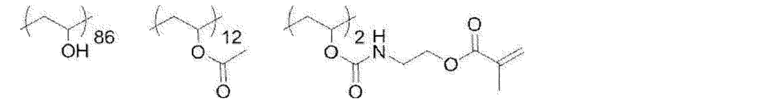
Modified polyvinyl alcohol:
(3)位相差層と選択反射層と偏光変換層との積層体の作製
(3-1)位相差層の作製
配向膜を形成したセルロースアシレートフィルムを、支持体(透明基材)として用いた。
支持体のうち配向膜の面に、支持体の長辺方向を基準に時計回りに45°回転させた方向にラビング処理を施した。具体的には、レーヨン布を用い、圧力:0.1kgf(0.98N)、回転数:1000rpm(revolutions per minute)、搬送速度:10m/min、回数:1往復の条件で行った。 (3) Preparation of Laminate of Retardation Layer, Selective Reflection Layer, and Polarization Conversion Layer (3-1) Preparation of Retardation Layer A cellulose acylate film having an orientation film formed thereon is used as a support (transparent substrate). board.
The orientation film surface of the support was rubbed in a direction rotated clockwise by 45° with respect to the long side direction of the support. Specifically, rayon cloth was used, pressure: 0.1 kgf (0.98 N), number of revolutions: 1000 rpm (revolutions per minute), conveying speed: 10 m/min, number of reciprocations: 1.
支持体上の配向膜のラビングした表面に、上記で調製した位相差層形成用塗布液をワイヤーバーを用いて塗布した後、乾燥させた。
次いで、50℃のホットプレート上に置き、酸素濃度1000ppm以下の環境で、フュージョンUVシステムズ社製の無電極ランプ「Dバルブ」(60mW/cm2)によって6秒間、紫外線を照射し、液晶相を固定した。これによりして、所望の正面位相差、すなわち、所望のリタデーションとなるように厚さを調整した位相差層を得た。
作製した位相差層のリタデーションをAxoScan(Axometrics社製、商品名)で測定したところ、126nmであった。 The rubbed surface of the alignment film on the support was coated with the above-prepared coating solution for forming a retardation layer using a wire bar, and then dried.
Next, it is placed on a hot plate at 50° C. and irradiated with ultraviolet rays for 6 seconds by an electrodeless lamp “D bulb” (60 mW/cm 2 ) manufactured by Fusion UV Systems in an environment with an oxygen concentration of 1000 ppm or less to convert the liquid crystal phase. Fixed. As a result, a retardation layer having a thickness adjusted to provide a desired frontal retardation, that is, a desired retardation, was obtained.
When the retardation of the produced retardation layer was measured by AxoScan (manufactured by Axometrics, trade name), it was 126 nm.
(3-2)選択反射層の作製
得られた位相差層の表面に、上記で調製したコレステリック液晶層(B1)形成用塗布液を、乾燥後の膜の厚さが後記表3に記載の膜厚になるようにワイヤーバーを用いて室温にて塗布して塗布層を得た。
塗布層を室温で30秒間乾燥させた後、85℃の雰囲気で2分間加熱した。その後、酸素濃度1000ppm以下の環境で、60℃でフュージョン社製のDバルブ(60mW/cm2のランプ)によって、出力60%で6~12秒間、紫外線を照射し、コレステリック液晶相を固定して、後記表3に記載の膜厚のコレステリック液晶層B1を得た。
次に、得られたコレステリック液晶層B1の表面に、コレステリック液晶層G1、及び、コレステリック液晶層R1を、後記表3に記載の膜厚となるようにしてこの順に積層し、位相差層の上に3層のコレステリック液晶層が積層されてなる積層体を得た。
なお、各コレステリック液晶層G1及びR1は、上記コレステリック液晶層B1の作製において、コレステリック液晶層(B1)形成用塗布液に代えて、対応する各コレステリック液晶層(G1及びR1)形成用塗布液を用いた以外は同様にして、1層ずつ作製した。 (3-2) Preparation of selective reflection layer On the surface of the obtained retardation layer, the coating liquid for forming the cholesteric liquid crystal layer (B1) prepared above is applied, and the thickness of the film after drying is shown in Table 3 below. A coating layer was obtained by coating at room temperature using a wire bar so as to obtain a film thickness.
After drying the coating layer at room temperature for 30 seconds, it was heated in an atmosphere of 85° C. for 2 minutes. After that, in an environment with an oxygen concentration of 1000 ppm or less, ultraviolet light is irradiated at 60° C. for 6 to 12 seconds with a D bulb (60 mW/cm 2 lamp) manufactured by Fusion Co., Ltd. at an output of 60% to fix the cholesteric liquid crystal phase. , to obtain a cholesteric liquid crystal layer B1 having a film thickness shown in Table 3 below.
Next, on the surface of the obtained cholesteric liquid crystal layer B1, a cholesteric liquid crystal layer G1 and a cholesteric liquid crystal layer R1 are laminated in this order so as to have the film thicknesses shown in Table 3 below, and on the retardation layer A laminate was obtained in which three layers of cholesteric liquid crystal layers were laminated on each other.
The cholesteric liquid crystal layers G1 and R1 are formed by using the corresponding cholesteric liquid crystal layer (G1 and R1) forming coating liquids instead of the cholesteric liquid crystal layer (B1) forming coating liquids in the preparation of the cholesteric liquid crystal layer B1. One layer at a time was prepared in the same manner except that the layer was used.
(3―3)偏光変換層の作製
次に、得られた積層体のうちコレステリック液晶層の最表面に、上記で調製した偏光変換層形成用塗布液を、膜厚1.7μmとなるように塗布して、偏光変換層(ツイスト層)を形成した。なお、偏光変換層の形成は、上述したコレステリック液晶層の作製において、コレステリック液晶層形成用塗布液に代えて偏光変換層形成用塗布液を用いた以外は同様にして作製した。
得られた偏光変換層は、選択反射中心波長λ10000nm、ピッチ数0.265のツイスト層であった。
このようにして、支持体(透明基材)上に、位相差層、選択反射層及び偏光変換層がこの順に積層されてなる積層体(この積層体を「P偏光反射フィルム」とも称す。)を作製した。 (3-3) Preparation of Polarization Conversion Layer Next, the coating solution for forming the polarization conversion layer prepared above was applied to the outermost surface of the cholesteric liquid crystal layer in the obtained laminate so as to have a thickness of 1.7 μm. By coating, a polarization conversion layer (twisted layer) was formed. The polarization conversion layer was formed in the same manner as in the preparation of the cholesteric liquid crystal layer described above, except that the coating liquid for forming the polarization conversion layer was used instead of the coating liquid for forming the cholesteric liquid crystal layer.
The resulting polarization conversion layer was a twisted layer with a selective reflection center wavelength of λ10000 nm and a pitch number of 0.265.
Thus, a laminate (this laminate is also referred to as a "P-polarized reflective film") in which the retardation layer, the selective reflection layer and the polarization conversion layer are laminated in this order on the support (transparent substrate). was made.
<1-2>選択反射層(誘電体多層膜)からなるP偏光反射フィルムの作製
特表平9-506837号公報に記載された方法に基づき、以下のようにして、直選択反射層(誘電体多層膜)からなるP偏光反射フィルムを作製した。 <1-2> Preparation of P-polarized reflective film composed of selective reflection layer (dielectric multilayer film) Based on the method described in Japanese Patent Application Laid-Open No. 9-506837, a direct selective reflection layer (dielectric A P-polarized reflective film consisting of a multilayer film) was produced.
特表平9-506837号公報に記載された方法に基づき、以下のようにして、直選択反射層(誘電体多層膜)からなるP偏光反射フィルムを作製した。 <1-2> Preparation of P-polarized reflective film composed of selective reflection layer (dielectric multilayer film) Based on the method described in Japanese Patent Application Laid-Open No. 9-506837, a direct selective reflection layer (dielectric A P-polarized reflective film consisting of a multilayer film) was produced.
2,6-ポリエチレンナフタレート(PEN)、及び、ナフタレート70モル%とテレフタレート30モル%とのコポリエステル(coPEN)を、ジオールとしてエチレングリコールを用いて、標準ポリエステル樹脂合成釜においてそれぞれ合成した。
得られたPEN及びcoPENの単層フィルムを押出成型し、約150℃で、延伸比5:1で延伸し、約230℃で30秒間、熱処理した。この延伸熱処理の結果、PENフィルムの遅相軸(配向軸)に関する屈折率は約1.86、横断軸に関する屈折率は1.64となり、coPENフィルムは等方性であり、屈折率は約1.64となることを確認した。 2,6-polyethylene naphthalate (PEN) and a copolyester of 70 mol % naphthalate and 30 mol % terephthalate (coPEN) were each synthesized in a standard polyester resin synthesis reactor using ethylene glycol as the diol.
The resulting monolayer films of PEN and coPEN were extruded, stretched at a draw ratio of 5:1 at about 150°C, and heat treated at about 230°C for 30 seconds. As a result of this stretching heat treatment, the PEN film has a refractive index of about 1.86 with respect to the slow axis (orientation axis) and a refractive index of 1.64 with respect to the transverse axis. 0.64.
次に、延伸比を調整することにより、PENフィルムの遅相軸に関する屈折率は約1.71、横断軸に関する屈折率は1.64となり、coPENフィルムは等方性であり、屈折率は約1.64となることを確認した。すなわち、光学異方性層であるPENフィルムの遅相軸方向の屈折率と、光学等方性層であるcoPENフィルムの屈折率との差Δnは0.07である。
Then, by adjusting the draw ratio, the PEN film has a refractive index about 1.71 for the slow axis and a refractive index about 1.64 for the transverse axis, and the coPEN film is isotropic, with a refractive index of about It was confirmed to be 1.64. That is, the difference Δn between the refractive index in the slow axis direction of the PEN film, which is the optically anisotropic layer, and the refractive index of the coPEN film, which is the optically isotropic layer, is 0.07.
続いて、PENおよびcoPENを同時押し出しして得られる積層体を、延伸し、熱処理することにより、P偏光反射フィルムを作製した。このP偏光反射フィルムの厚さは約18.6μmであり、下記表2のP偏光反射層(1)~(6)をこの順に有する。各P偏光反射層は、各P偏光反射層の列に示す膜厚のPENとcoPENとを交互に16層ずつ有する層である。
具体的には、特表平9-506837号公報の実施例1に記載の条件と同様にして、標準押出ダイを装着した32スロット供給ブロックを用いて、下記表2のP偏光反射層(1)~(6)に対応する延伸前の各積層体を、所望の選択反射中心波長(5°)の光学的4分の1波長厚さになる様にPEN及びcoPENの押出速度を調製してそれぞれ作製した後、これらを全て積層した積層体について、約150℃において5:1の延伸比で1軸延伸を行い、延伸した積層体を、エアーオーブン内において、約230℃で30秒間、熱処理して、P偏光反射フィルムを作製した。
なお、表2に記載の選択反射中心波長は、後述の[評価α]選択反射層の反射スペクトルの測定により測定した値である。 Subsequently, a laminate obtained by coextrusion of PEN and coPEN was stretched and heat-treated to produce a P-polarized reflective film. This P-polarized reflective film has a thickness of about 18.6 μm and has P-polarized reflective layers (1) to (6) in Table 2 below in this order. Each P-polarized reflective layer is a layer having 16 layers of PEN and coPEN alternately having the film thickness shown in the row of each P-polarized reflective layer.
Specifically, using a 32-slot feed block equipped with a standard extrusion die, the P-polarized reflective layer (1 ) to (6), the extrusion speed of PEN and coPEN is adjusted so that each laminate before stretching has an optical quarter-wave thickness of the desired selective reflection center wavelength (5 °). After each preparation, the laminate obtained by laminating all of these was uniaxially stretched at about 150°C with a draw ratio of 5:1, and the stretched laminate was heat-treated in an air oven at about 230°C for 30 seconds. Then, a P-polarized reflective film was produced.
The selective reflection central wavelengths listed in Table 2 are values measured by measuring the reflection spectrum of the [Evaluation α] selective reflection layer described later.

〔2〕ウィンドシールドガラスの作製
<2-1>コレステリック液晶層からなる選択反射層を有するウィンドシールドガラスの作製
上記で作製した、支持体(透明基材)、位相差層、選択反射層、及び、偏光変換層がこの順に積層されてなる積層体を用い、第1のガラス板、中間膜、偏光変換層、選択反射層(コレステリック液晶層)、位相差層、支持体(透明基材)、ヒートシール層、及び、第2のガラス板がこの順に積層されてなる積層体を作製した。
なお、上記の積層体におけるヒートシール層は、コレステリック液晶層からなる選択反射層の支持体(透明基材)側にヒートシール層形成用塗布液をワイヤーバーを用いて塗布後、乾燥させて50℃にて1分間加熱処理を行うことにより、厚み1μmのヒートシール層を形成した。
得られた積層体を90℃、10kPa(0.1気圧)下で一時間保持した後に、オートクレーブ(栗原製作所製)にて115℃、1.3MPa(13気圧)で20分間加熱して気泡を除去し、コレステリック液晶層からなる選択反射層を有するウィンドシールドガラスAを得た。 [2] Preparation of windshield glass <2-1> Preparation of windshield glass having a selective reflection layer composed of a cholesteric liquid crystal layer The support (transparent substrate), the retardation layer, the selective reflection layer, and , using a laminate in which polarization conversion layers are laminated in this order, a first glass plate, an intermediate film, a polarization conversion layer, a selective reflection layer (cholesteric liquid crystal layer), a retardation layer, a support (transparent substrate), A laminate was produced by laminating the heat seal layer and the second glass plate in this order.
The heat-seal layer in the above laminate is obtained by applying a heat-seal layer-forming coating liquid to the support (transparent substrate) side of the selective reflection layer made of the cholesteric liquid crystal layer using a wire bar and then drying it for 50 minutes. A heat seal layer having a thickness of 1 µm was formed by heat-treating at °C for 1 minute.
After holding the obtained laminate at 90° C. and 10 kPa (0.1 atmosphere) for 1 hour, it was heated in an autoclave (manufactured by Kurihara Seisakusho) at 115° C. and 1.3 MPa (13 atmospheres) for 20 minutes to remove air bubbles. It was removed to obtain a windshield glass A having a selective reflection layer consisting of a cholesteric liquid crystal layer.
<2-2>誘電体多層膜からなる選択反射層を有するウィンドシールドガラスの作製
上記で作製した誘電体多層膜からなるP偏光反射フィルムを用い、第2のガラス板、中間膜、選択反射層(誘電体多層膜)、中間膜、及び、第1のガラス板がこの順に積層されてなる積層体を作製した。得られた積層体を90℃、10kPa(0.1気圧)下で一時間保持した後に、オートクレーブ(栗原製作所製)にて115℃、1.3MPa(13気圧)で20分間加熱して気泡を除去し、ウィンドシールドガラスBを得た。
なお、P偏光反射フィルムにおけるP偏光反射層(1)が第2のガラス板側となり、P偏光反射層(6)が第1のガラス板側になるようにして積層した。 <2-2> Preparation of windshield glass having a selective reflection layer made of a dielectric multilayer film Using the P-polarized reflection film made of the dielectric multilayer film prepared above, a second glass plate, an intermediate film, and a selective reflection layer are formed. (dielectric multilayer film), an intermediate film, and a first glass plate were laminated in this order to produce a laminate. After holding the obtained laminate at 90° C. and 10 kPa (0.1 atmosphere) for 1 hour, it was heated in an autoclave (manufactured by Kurihara Seisakusho) at 115° C. and 1.3 MPa (13 atmospheres) for 20 minutes to remove air bubbles. It was removed to obtain windshield glass B.
The P-polarized light reflective layer (1) of the P-polarized light reflective film was placed on the second glass plate side, and the P-polarized light reflective layer (6) was placed on the first glass plate side.
上記ウィンドシールドガラスは、上記第1のガラス板及び第2のガラス板と同じ形状に、各層をカッティングして使用した。
上記ウィンドシールドガラスの作製に用いたガラス板、中間膜、ヒートシール層形成用塗布液は、それぞれ下記の通りである。
第1のガラス板及び第2のガラス板として、縦120mm×横100mm、厚さ2mmのガラス板(セントラル硝子社製、FL2、可視光線透過率90%)を使用した。
また、中間膜として、積水化学社製の厚さ0.38mmのPVB(ポリビニルブチラール)フィルムを使用した。
また、ヒートシール層の作製には、下記成分を下記に示す組成比となるように混合、調製した、ヒートシール層形成用塗布液を使用した。
(ヒートシール層形成用塗布液)
・PVBシート片(積水化学社製、エスレックフィルム) 5.0質量部
・メタノール 90.25質量部
・ブタノール 4.75質量部 The windshield glass was used by cutting each layer into the same shape as the first glass plate and the second glass plate.
The glass plate, the intermediate film, and the coating solution for forming the heat seal layer used for the production of the windshield glass are as follows.
As the first glass plate and the second glass plate, glass plates having a length of 120 mm, a width of 100 mm, and a thickness of 2 mm (FL2, visible light transmittance of 90%, manufactured by Central Glass Co., Ltd.) were used.
A 0.38 mm-thick PVB (polyvinyl butyral) film manufactured by Sekisui Chemical Co., Ltd. was used as an intermediate film.
Also, for the production of the heat seal layer, a heat seal layer-forming coating liquid prepared by mixing the following components so as to have the composition ratio shown below was used.
(Coating liquid for forming heat seal layer)
・PVB sheet piece (manufactured by Sekisui Chemical Co., Ltd., S-lec film) 5.0 parts by mass ・Methanol 90.25 parts by mass ・Butanol 4.75 parts by mass
下記表3に、ウィンドシールドガラスA及びBにおける選択反射層に係る構成をまとめて示す。なお、後述のHUDシステムの設計においては、各ウィンドシールドガラスにおける第2のガラス板側に画像表示光が入射するように配置して使用した。
Table 3 below summarizes the configurations related to the selective reflection layers in the windshield glasses A and B. In the design of the HUD system, which will be described later, each windshield glass is arranged so that the image display light is incident on the second glass plate side.
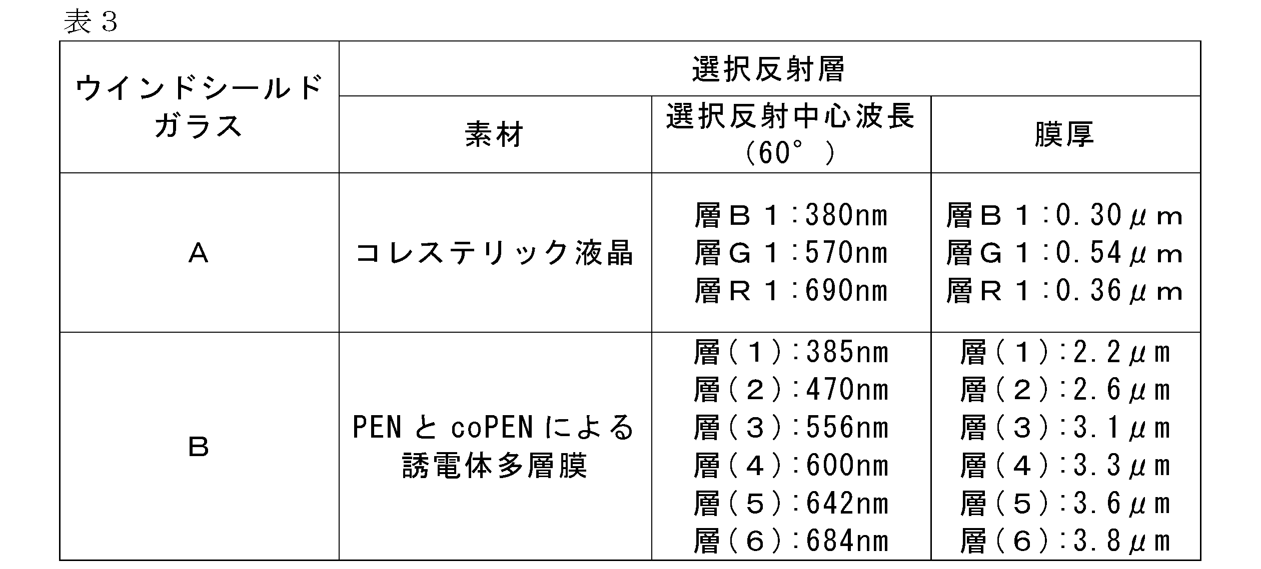
〔3〕正の回折反射素子の作製
<3-1>反射型の液晶回折素子の作製
支持体上に形成した下塗り層上に配向膜を形成し、この配向膜にレーザー光を照射し、2つのレーザー光の交差角を変化させることにより干渉パターン(表面周期構造)を制御し、硬化させた。得られた光配向膜の上に液晶層を形成することにより、反射型の液晶回折素子を作製した。
具体的には、国際公開第2019/131966号の実施例2に記載の反射型の液晶回折素子の作製において、下記表4に示す所望の回折反射が得られる様に、国際公開第2019/131966号の図5に示す露光装置によって配向膜を露光する際の2つのレーザー光の交差角を変更した以外は同様にして、B反射層、G反射層及びR反射層がこの順に、接着剤(綜研化学社製、商品名:SKダイン2075)で張り合わされてなる、反射型の液晶回折素子を作製した。
なお、表4に記載の選択反射中心波長は、後述の[評価α]選択反射層の反射スペクトルの測定により測定した値であり、1周期とは、液晶化合物由来の光学軸が180°回転する長さを意味する。 [3] Fabrication of Positive Diffractive Reflective Element <3-1> Fabrication of Reflective Liquid Crystal Diffractive Element An alignment film is formed on an undercoat layer formed on a support. The interference pattern (surface periodic structure) was controlled and cured by changing the crossing angle of the two laser beams. A reflective liquid crystal diffraction element was produced by forming a liquid crystal layer on the obtained photo-alignment film.
Specifically, in the preparation of the reflective liquid crystal diffraction element described in Example 2 of International Publication No. 2019/131966, the desired diffraction reflection shown in Table 4 below is obtained. The B reflective layer, the G reflective layer and the R reflective layer are formed in this order in the same manner except that the crossing angle of the two laser beams when the alignment film is exposed by the exposure apparatus shown in FIG. A reflective liquid crystal diffraction element was produced by laminating with Soken Kagaku Co., Ltd., trade name: SK Dyne 2075).
The selective reflection center wavelengths listed in Table 4 are values measured by measuring the reflection spectrum of the [Evaluation α] selective reflection layer described later, and one cycle means that the optical axis derived from the liquid crystal compound rotates 180°. means length.

上記のようにして作製した反射型の液晶回折素子は、反射に偏光特性があり、円偏光を回折反射する。このため、後述のHUDシステムの設計においては、反射型の液晶回折素子におけるR反射層側を1/4波長板(帝人社製、商品名:ピュアエースWR-S、ポリカーボネートフィルム、正面リタデーションが126nm)と貼合せ、この1/4波長板側に画像表示装置からの光が入射するようにして配置することにより、P偏光を反射する回折反射素子として使用した。
The reflective liquid crystal diffraction element manufactured as described above has polarization characteristics in reflection, and diffracts and reflects circularly polarized light. For this reason, in the design of the HUD system described later, the R reflective layer side of the reflective liquid crystal diffraction element is a 1/4 wavelength plate (manufactured by Teijin, trade name: Pure Ace WR-S, polycarbonate film, front retardation is 126 nm ), and arranged so that the light from the image display device is incident on the quarter-wave plate side, thereby using as a diffraction reflection element for reflecting P-polarized light.
<3-2>反射型のホログラム素子の作製
感光性材料である重クロム酸ゼラチン対して、レーザー光をビームスプリッターにより2つに分離し、この分離した2つのレーザー光を用い、物体光の振幅及び位相の情報を、参照光との干渉パターン(周期的な屈折率分布)として作り、感光性材料に屈折率分布ができたところで硬化し、下記表5に示す所望の回折反射を示す体積型の反射ホログラム素子を作製した。得られた体積型の反射ホログラム素子においては、その表面の屈折率分布の周期が回折格子となる。 <3-2> Fabrication of reflective hologram element A laser beam is split into two beams by a beam splitter on gelatin bichromate, which is a photosensitive material. And the phase information is produced as an interference pattern (periodic refractive index distribution) with the reference light, and the photosensitive material is cured when the refractive index distribution is formed, and the volume type exhibits the desired diffraction reflection shown in Table 5 below. A reflection hologram element was produced. In the obtained volume-type reflection hologram element, the period of the refractive index distribution on the surface becomes a diffraction grating.
感光性材料である重クロム酸ゼラチン対して、レーザー光をビームスプリッターにより2つに分離し、この分離した2つのレーザー光を用い、物体光の振幅及び位相の情報を、参照光との干渉パターン(周期的な屈折率分布)として作り、感光性材料に屈折率分布ができたところで硬化し、下記表5に示す所望の回折反射を示す体積型の反射ホログラム素子を作製した。得られた体積型の反射ホログラム素子においては、その表面の屈折率分布の周期が回折格子となる。 <3-2> Fabrication of reflective hologram element A laser beam is split into two beams by a beam splitter on gelatin bichromate, which is a photosensitive material. And the phase information is produced as an interference pattern (periodic refractive index distribution) with the reference light, and the photosensitive material is cured when the refractive index distribution is formed, and the volume type exhibits the desired diffraction reflection shown in Table 5 below. A reflection hologram element was produced. In the obtained volume-type reflection hologram element, the period of the refractive index distribution on the surface becomes a diffraction grating.

上記のようにして作製した体積型の反射ホログラム素子は、反射に偏光特性を持たず、無偏光を回折反射する。
The volume-type reflection hologram element produced as described above does not have polarization characteristics for reflection, and diffracts and reflects non-polarized light.
〔4〕1/2波長板の作製
2枚の1/4波長板(帝人社製、商品名:ピュアエースWR-S、ポリカーボネートフィルム、正面リタデーションが126nm)をOCAテープ(日栄化工社製、商品名:MHM-UVC15、厚さ15μm)を用いて貼合し、1/2波長板を作製した。
後述のHUDシステムの設計においては、透過光が所望の偏光になる様に、1/2波長板を回転させて遅相軸の方向を合せて配置して使用した。 [4] Preparation of 1/2 wavelength plate Two 1/4 wavelength plates (manufactured by Teijin, product name: Pure Ace WR-S, polycarbonate film, front retardation 126 nm) OCA tape (manufactured by Nichiei Kako, product (name: MHM-UVC15, thickness 15 μm)) to produce a half-wave plate.
In the design of the HUD system described later, the half-wave plate was rotated to match the direction of the slow axis and used so that the transmitted light would have the desired polarization.
〔5〕負の透過型光学素子の作製
<5-1>透過型の液晶回折素子の作製
支持体上に形成した下塗り層上に配向膜を形成し、この配向膜にレーザー光を照射し、2つのレーザー光の交差角を変化させることにより干渉パターン(表面周期構造)を制御し、硬化させた。得られた光配向膜の上に、棒状液晶を捩らず(カイラル剤を配合せず)に液晶層を形成することにより、透過型の液晶回折素子を作製した。
具体的には、国際公開第2020/022513号の実施例2に記載の透過型の光学異方性部材(透過型の液晶回折素子)の作製に従って、透過型の液晶回折素子を作製した。なお、液晶化合物由来の光学軸が180°回転する長さ(1周期)は、素子の中心部では約10μmであり、素子の端部では約1μmとなるように設計した。
後述のHUDシステムの設計においては、上記で作製した透過型の液晶回折素子をそのまま、液晶層側に画像表示装置からの光が入射するようにして配置して使用した。 [5] Production of Negative Transmission Type Optical Element <5-1> Production of Transmission Type Liquid Crystal Diffractive Element The interference pattern (surface periodic structure) was controlled by changing the crossing angle of the two laser beams to effect curing. A transmissive liquid crystal diffraction element was produced by forming a liquid crystal layer on the obtained photo-alignment film without twisting the rod-like liquid crystal (without adding a chiral agent).
Specifically, a transmission-type liquid crystal diffraction element was produced according to the production of a transmission-type optically anisotropic member (transmission-type liquid crystal diffraction element) described in Example 2 of WO2020/022513. It should be noted that the length (one cycle) over which the optical axis derived from the liquid crystal compound rotates by 180° was designed to be about 10 µm at the center of the device and about 1 µm at the edge of the device.
In the design of the HUD system described later, the transmissive liquid crystal diffraction element manufactured above was used as it was arranged so that the light from the image display device was incident on the liquid crystal layer side.
<5-2>透過型のホログラム素子の作製
上記<3-2>反射型のホログラム素子の作製において、透過型となるように干渉パターンを調製した以外は同様にして、体積型の透過ホログラム素子を作製した。得られた体積型の反射ホログラム素子においては、その表面の屈折率分布の周期が回折格子となる。 <5-2> Fabrication of transmission hologram element <3-2> Fabrication of reflection type hologram element, except that the interference pattern is prepared so as to be a transmission type, in the same manner as above, to obtain a volume transmission hologram element. was made. In the obtained volume-type reflection hologram element, the period of the refractive index distribution on the surface becomes a diffraction grating.
上記<3-2>反射型のホログラム素子の作製において、透過型となるように干渉パターンを調製した以外は同様にして、体積型の透過ホログラム素子を作製した。得られた体積型の反射ホログラム素子においては、その表面の屈折率分布の周期が回折格子となる。 <5-2> Fabrication of transmission hologram element <3-2> Fabrication of reflection type hologram element, except that the interference pattern is prepared so as to be a transmission type, in the same manner as above, to obtain a volume transmission hologram element. was made. In the obtained volume-type reflection hologram element, the period of the refractive index distribution on the surface becomes a diffraction grating.
<5-3>凹レンズ
ウインドシールガラスのサイズ、ウィンドシールドガラスと虚像表示装置との距離、HUDシステムに用いられるその他の光学部材に合わせて、必要な曲率の凹レンズを、通常の方法で作製した。 <5-3> Concave Lens A concave lens having a necessary curvature was produced by a normal method according to the size of the windshield glass, the distance between the windshield glass and the virtual image display device, and other optical members used in the HUD system.
ウインドシールガラスのサイズ、ウィンドシールドガラスと虚像表示装置との距離、HUDシステムに用いられるその他の光学部材に合わせて、必要な曲率の凹レンズを、通常の方法で作製した。 <5-3> Concave Lens A concave lens having a necessary curvature was produced by a normal method according to the size of the windshield glass, the distance between the windshield glass and the virtual image display device, and other optical members used in the HUD system.
[ヘッドアップディスプレイシステム(HUDシステム)の設計]
上記で作製したウィンドシールドガラス、正の回折反射素子、1/2波長板及び負の透過型光学素子と下記画像表示装置を用いて、表6に示すHUDシステムNo.101~107及びc11を設計した。
HUDシステムNo.101は図1に示す構成となるように、HUDシステムNo.102~104は図2に示す構成となるように、HUDシステムNo.105~107は図3に示す構成となるようにして、それぞれ配置した。なお、HUDシステムNo.104については、図2に示す構成において、ヒートシール層に代えて中間膜を配した構成となっている。これらのHUDシステムNo.101~107は本発明の虚像表示装置を備えたHUDシステムである。
一方、表6に示すHUDシステムNo.c11は、上記で作製した正の回折反射素子及び負の透過型光学素子と下記画像表示装置とガラスとを用いて設計した、比較のための虚像表示装置を備えたHUDシステムである。HUDシステムNo.c11は、図3において、1/2波長板5A及び5Bを有さず、ウィンドシールドガラス24に代えてガラスを用いた以外は同様の構成となるようにして配置した。 [Design of head-up display system (HUD system)]
Using the windshield glass, positive diffractive reflective element, half-wave plate and negative transmissive optical element prepared above and the following image display device, HUD system No. 1 shown in Table 6 was used. 101-107 and c11 were designed.
HUD system no. 101 designates HUD system No. 1 so as to have the configuration shown in FIG. 102 to 104 are configured as shown in FIG. 105 to 107 were arranged so as to have the configuration shown in FIG. Note that the HUD system No. 104 has a configuration in which an intermediate film is arranged in place of the heat seal layer in the configuration shown in FIG. These HUD system nos. 101 to 107 are HUD systems equipped with the virtual image display device of the present invention.
On the other hand, HUD system No. shown in Table 6. c11 is a HUD system equipped with a virtual image display device for comparison, which was designed using the positive diffractive reflective element and the negative transmissive optical element fabricated above, the image display device described below, and glass. HUD system no. c11 has the same configuration as in FIG.
画像表示装置としては、ライトフィールドディスプレイを使用した。
また、画像表示装置の出射光の偏光として、直線偏光であって、かつ、S偏光から10°程偏光の方位を回転したものを使用した。
なお、No.101~107のHUDシステムにおいては、正の回折反射素子に入射される光が回折効率の良いS偏光となり、ウィンドシールドガラスに入射する際にはP偏光になるように、配置角度等を調整した。
No.c11のHUDシステム等のウィンドシールドガラスがくさび型ガラスであって、S偏光を反射する場合にも、上記のS偏光から10°程偏光の方位を回転した直線偏光を使用することにより、偏光サングラスを着用した状態でも、わずかでもHUD画像を見える様に設計されることがある。そのため、No.c11のHUDシステムにおいては、上記の様なHUDシステムを再現し、正の回折反射素子に対してS偏光から10°程偏光の方位を回転した直線偏光が入射し、S偏光から10°程偏光の方位を回転した直線偏光がガラスに入射するように、配置角度等を調整した。 A light field display was used as an image display device.
In addition, as the polarized light emitted from the image display device, linearly polarized light whose direction of polarization is rotated by about 10° from S-polarized light is used.
In addition, No. In the HUD systems 101 to 107, the arrangement angle etc. were adjusted so that the light incident on the positive diffractive reflection element becomes S-polarized light with good diffraction efficiency, and becomes P-polarized light when incident on the windshield glass. .
No. Even if the windshield glass of the c11 HUD system is a wedge-shaped glass and reflects S-polarized light, polarized sunglasses can be obtained by using linearly polarized light whose orientation is rotated by about 10° from the S-polarized light. It may be designed so that the HUD image can be seen, even if only slightly, while wearing the . Therefore, No. In the HUD system of c11, the above HUD system is reproduced, and linearly polarized light whose direction of polarization is rotated by about 10° from S-polarized light is incident on the positive diffractive reflection element, and polarized light is polarized by about 10° from S-polarized light The arrangement angle and the like were adjusted so that the linearly polarized light whose azimuth was rotated was incident on the glass.
以下のようにして、輝度、偏光サングラス着用時の輝度、及び、色収差の評価を、ウィンドシールドガラスから1m離れた位置(図1~3における観察者Dの位置関係に相当)を観察点として目視で行った。これらの結果をまとめて後記表6に示す。
Visually evaluate the luminance, luminance when wearing polarized sunglasses, and chromatic aberration in the following manner, using a position 1 m away from the windshield glass (equivalent to the positional relationship of observer D in FIGS. 1 to 3) as an observation point. I went with These results are collectively shown in Table 6 below.
[評価α]選択反射層の反射スペクトルの測定
作製したウィンドシールドガラスのうち、第1のガラス板側の裏面に黒色PET(ポリエチレンテレフタレート)フィルム(光吸収体)を貼り合わせた。
分光光度計(日本分光株式会社製、商品名:V-670)を用いて、ウィンドシールドガラスの第2のガラス板から、ウィンドシールドガラス表面の法線方向に対し所望の角度の方向からP偏光又はS偏光をそれぞれ入射し、波長300~800nmの帯域におけるP偏光及びS偏光の反射スペクトルをそれぞれ測定した。測定したP偏光の反射スペクトルとS偏光の反射スペクトルの平均値(平均の反射スペクトル)を求めた。
本発明において、選択反射中心波長(60°)は、ウィンドシールドガラス表面の法線方向に対し60°の角度で光入射して測定した反射スペクトルに基づき算出し、選択反射中心波長(5°)は、ウィンドシールドガラス表面の法線方向に対し5°の角度で光入射して測定した反射スペクトルに基づき算出した値を意味する。
なお、P偏光の反射スペクトルとS偏光の反射スペクトルの平均値は、自然光を入射した際の反射スペクトルと同義である。 [Evaluation α] Measurement of Reflection Spectrum of Selective Reflection Layer A black PET (polyethylene terephthalate) film (light absorber) was attached to the rear surface of the first glass plate of the prepared windshield glass.
Using a spectrophotometer (manufactured by JASCO Corporation, trade name: V-670), from the second glass plate of the windshield glass, P-polarized light is emitted from the direction of a desired angle with respect to the normal direction of the windshield glass surface. Alternatively, S-polarized light was incident, and reflection spectra of P-polarized light and S-polarized light were measured in a wavelength band of 300 to 800 nm. An average value (average reflection spectrum) of the measured P-polarized reflection spectrum and S-polarized reflection spectrum was obtained.
In the present invention, the selective reflection central wavelength (60°) is calculated based on the reflection spectrum measured by light incident at an angle of 60° with respect to the normal direction of the windshield glass surface, and the selective reflection central wavelength (5°) means a value calculated based on a reflection spectrum measured by light incident at an angle of 5° with respect to the normal direction of the windshield glass surface.
The average value of the P-polarized reflection spectrum and the S-polarized reflection spectrum is synonymous with the reflection spectrum when natural light is incident.
[評価1]輝度の評価
黒地に白色文字の画像を画像表示装置により表示し、目視で観察した文字の見え方を下記評価基準に当てはめ、輝度を評価した。
- 評価基準(輝度) -
A:文字は晴天時の屋外で可読、かつ、室内照明下で可読。
A-:文字は晴天時の屋外でやや難読、かつ、室内照明下で可読。
B:文字は晴天時の屋外でやや難読、かつ、室内照明下でやや難読。
C:文字は屋外で難読、かつ、室内照明下でやや難読。 [Evaluation 1] Evaluation of Brightness An image of white characters was displayed on a black background using an image display device, and the appearance of the characters visually observed was applied to the following evaluation criteria to evaluate the brightness.
- Evaluation criteria (luminance) -
A: Characters are readable outdoors in fine weather and readable under indoor lighting.
A- : Characters are somewhat difficult to read outdoors in fine weather, and readable under indoor lighting.
B: Characters are slightly illegible outdoors in fine weather and somewhat illegible under indoor lighting.
C: Letters are illegible outdoors and somewhat illegible under indoor lighting.
[評価2]偏光サングラス着用時の輝度の評価
黒地に白色文字を画像表示装置により表示し、偏光サングラスを着用した状態で目視で観察した文字の見え方を下記評価基準に当てはめ、偏光サングラス着用時の輝度を評価した。
本試験においては、評価「A」~「B」が合格レベルである。
- 評価基準(偏光サングラス着用時の輝度) -
A:文字は晴天時の屋外で可読、かつ、室内照明下で可読。
A-:文字は晴天時の屋外でやや難読、かつ、室内照明下で可読。
B:文字は晴天時の屋外でやや難読、かつ、室内照明下でやや難読。
C:文字は屋外で見えず、かつ、室内照明下で見えない。 [Evaluation 2] Evaluation of brightness when wearing polarized sunglasses Display white characters on a black background using an image display device, and apply the appearance of the characters visually observed while wearing polarized sunglasses to the following evaluation criteria, when wearing polarized sunglasses were evaluated for brightness.
In this test, evaluations "A" to "B" are pass levels.
- Evaluation criteria (luminance when wearing polarized sunglasses) -
A: Characters are readable outdoors in fine weather and readable under indoor lighting.
A- : Characters are somewhat difficult to read outdoors in fine weather, and readable under indoor lighting.
B: Characters are slightly illegible outdoors in fine weather and somewhat illegible under indoor lighting.
C: Letters are invisible outdoors and invisible under indoor lighting.
[評価3]色収差の評価
黒地に建物の写真を画像表示装置により表示し、目視で観察した色ずれ(すなわち、赤、青及び緑の画像の位置ずれ)を下記評価基準に当てはめ、色収差を評価した。
本試験においては、評価「A」及び「B」が色収差が良好であり、好ましいレベルである。
- 評価基準(色収差) -
A:色ずれはほとんどわからない。
B:建物の端部でわずかに色ずれが見える。
C:色ずれが顕著に見える。 [Evaluation 3] Evaluation of Chromatic Aberration A photograph of a building is displayed on a black background using an image display device, and the visually observed color shift (that is, position shift of red, blue and green images) is applied to the following evaluation criteria to evaluate chromatic aberration. bottom.
In this test, the evaluations "A" and "B" are favorable levels of chromatic aberration.
- Evaluation criteria (chromatic aberration) -
A: Almost no color shift is observed.
B: Slight color shift can be seen at the edge of the building.
C: Color misregistration is conspicuous.
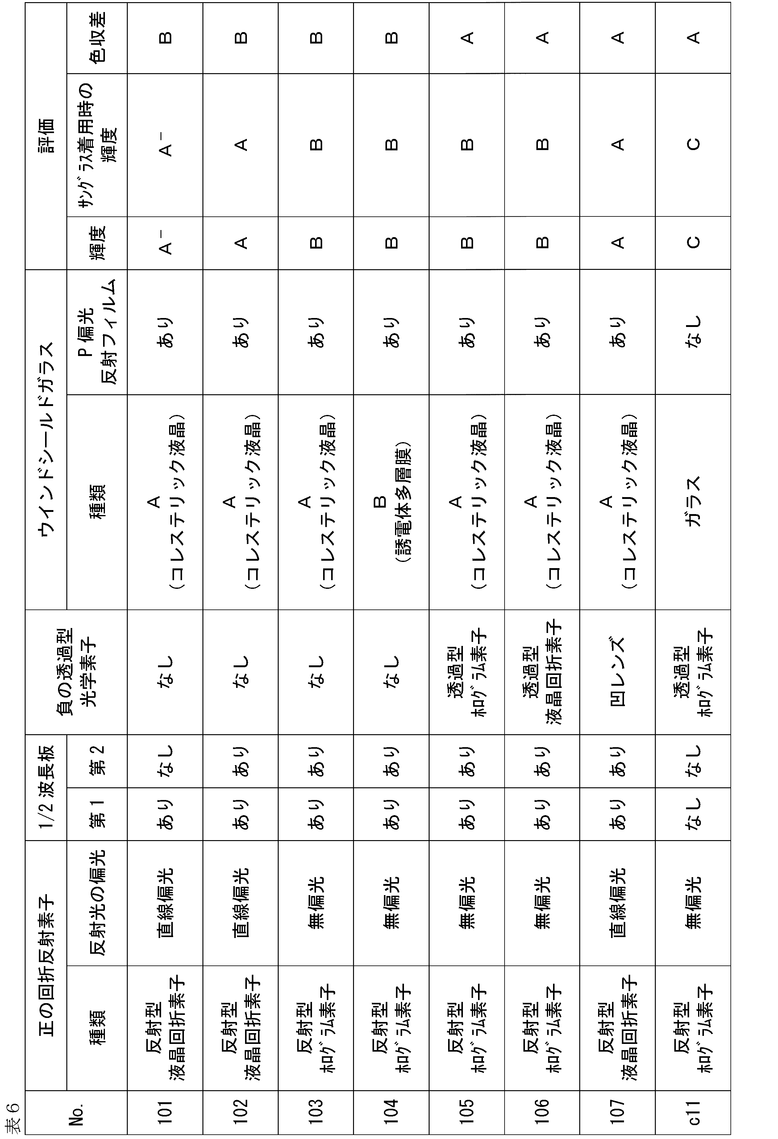
(表の注)
ウィンドシールドガラス、正の回折反射素子、1/2波長板及び負の透過型光学素子は、それぞれ上述で作製した通りである。
正の回折反射素子のうち反射型液晶回折素子の反射光の偏光は、1/4波長板を重ねて用いているため直線偏光となる。
1/2波長板のうち、第1の欄に記載の1/2波長板は、投映画像光を投映部に導光する光路上、光学パワーが正の回折反射素子とウィンドシールドガラスとの間に位置するようにして配置する。一方、第2の欄に記載の1/2波長板は、投映画像光を投映部に導光する光路上、画像表示装置と光学パワーが負の透過型光学素子との間、または、負の透過型光学素子を有しない場合には画像表示装置と正の回折反射素子との間に位置するようにして配置する。 (Note to table)
The windshield glass, positive diffractive reflective element, half-wave plate and negative transmissive optical element were each fabricated as described above.
Polarization of the reflected light from the reflective liquid crystal diffraction element, which is one of the positive diffraction reflection elements, is linearly polarized because the 1/4 wavelength plate is superimposed thereon.
Of the half-wave plates, the half-wave plate described in the first column is placed between the diffraction reflective element with positive optical power and the windshield glass on the optical path that guides the projection image light to the projection unit. Place it so that it is positioned at On the other hand, the half-wave plate described in the second column is placed between the image display device and the transmissive optical element with negative optical power, or on the optical path for guiding the projected image light to the projection unit. If no transmissive optical element is provided, it is positioned between the image display device and the positive diffractive reflective element.
表6の結果から、以下のことがわかる。
特許文献1に記載されるように、本発明で規定する1/2波長板を備えない虚像表示装置であって、画像表示装置からの投映画像光を光学パワーが正の回折反射素子により回折して投映部にS偏光の画像表示光を入射するNo.c11のHUDシステムにおける虚像表示装置では、S偏光反射機能を備えるウィンドシールドガラスと組み合わせて用いた場合、投映される文字は屋外で難読、かつ、室内照明下でやや難読であり、サングラス着用時には屋外及び室内照明下のいずれも見えず、輝度に劣っていた。
これに対して、本発明で規定する1/2波長板を備え、画像表示装置からの投映画像光を光学パワーが正の回折反射素子により回折して投映部にP偏光の画像表示光が入射するNo.101~107のHUDシステムにおける虚像表示装置では、P偏光反射機能を備えるウィンドシールドガラスと組み合わせて用いた場合、投映される文字は、サングラスの着用の有無に関わらず読むことが可能であり(評価1及び2における輝度の評価がいずれも「A」~「B」)、No.c11のHUDシステムにおける虚像表示装置に対して、優れた輝度を示していた。
また、本発明の虚像表示装置を備えたHUDシステムNo.101~107は、色収差についても良好なレベルを示していた。 The results in Table 6 show the following.
As described in Patent Document 1, there is provided a virtual image display device without a half-wave plate defined in the present invention, in which projection image light from an image display device is diffracted by a diffraction reflection element having a positive optical power. No. 1, which makes S-polarized image display light incident on the projection unit. In the virtual image display device in the c11 HUD system, when used in combination with a windshield glass equipped with an S-polarization reflection function, the projected characters are difficult to read outdoors and somewhat difficult to read under indoor lighting. and under indoor lighting, the brightness was poor.
On the other hand, the 1/2 wavelength plate specified in the present invention is provided, and the projected image light from the image display device is diffracted by the diffraction reflection element having a positive optical power, and the P-polarized image display light is incident on the projection unit. No. to do 101 to 107, when used in combination with a windshield glass having a P-polarized reflection function, the projected characters can be read regardless of whether sunglasses are worn (evaluation 1 and 2 are both rated as "A" to "B"); It showed excellent brightness for the virtual image display in the HUD system of c11.
Also, a HUD system No. 1 equipped with the virtual image display device of the present invention. 101 to 107 also showed good levels of chromatic aberration.
特許文献1に記載されるように、本発明で規定する1/2波長板を備えない虚像表示装置であって、画像表示装置からの投映画像光を光学パワーが正の回折反射素子により回折して投映部にS偏光の画像表示光を入射するNo.c11のHUDシステムにおける虚像表示装置では、S偏光反射機能を備えるウィンドシールドガラスと組み合わせて用いた場合、投映される文字は屋外で難読、かつ、室内照明下でやや難読であり、サングラス着用時には屋外及び室内照明下のいずれも見えず、輝度に劣っていた。
これに対して、本発明で規定する1/2波長板を備え、画像表示装置からの投映画像光を光学パワーが正の回折反射素子により回折して投映部にP偏光の画像表示光が入射するNo.101~107のHUDシステムにおける虚像表示装置では、P偏光反射機能を備えるウィンドシールドガラスと組み合わせて用いた場合、投映される文字は、サングラスの着用の有無に関わらず読むことが可能であり(評価1及び2における輝度の評価がいずれも「A」~「B」)、No.c11のHUDシステムにおける虚像表示装置に対して、優れた輝度を示していた。
また、本発明の虚像表示装置を備えたHUDシステムNo.101~107は、色収差についても良好なレベルを示していた。 The results in Table 6 show the following.
As described in Patent Document 1, there is provided a virtual image display device without a half-wave plate defined in the present invention, in which projection image light from an image display device is diffracted by a diffraction reflection element having a positive optical power. No. 1, which makes S-polarized image display light incident on the projection unit. In the virtual image display device in the c11 HUD system, when used in combination with a windshield glass equipped with an S-polarization reflection function, the projected characters are difficult to read outdoors and somewhat difficult to read under indoor lighting. and under indoor lighting, the brightness was poor.
On the other hand, the 1/2 wavelength plate specified in the present invention is provided, and the projected image light from the image display device is diffracted by the diffraction reflection element having a positive optical power, and the P-polarized image display light is incident on the projection unit. No. to do 101 to 107, when used in combination with a windshield glass having a P-polarized reflection function, the projected characters can be read regardless of whether sunglasses are worn (
Also, a HUD system No. 1 equipped with the virtual image display device of the present invention. 101 to 107 also showed good levels of chromatic aberration.
本発明をその実施態様とともに説明したが、我々は特に指定しない限り我々の発明を説明のどの細部においても限定しようとするものではなく、添付の請求の範囲に示した発明の精神と範囲に反することなく幅広く解釈されるべきであると考える。
While we have described our invention in conjunction with embodiments thereof, we do not intend to limit our invention in any detail to the description unless specified otherwise, which is contrary to the spirit and scope of the invention as set forth in the appended claims. I think it should be interpreted broadly.
本願は、2021年11月5日に日本国で特許出願された特願2021-181368に基づく優先権を主張するものであり、これはここに参照してその内容を本明細書の記載の一部として取り込む。
This application claims priority based on Japanese Patent Application No. 2021-181368 filed in Japan on November 5, 2021, the contents of which are incorporated herein by reference. taken in as a part.
1 虚像表示装置
2 画像表示装置
3 正の回折反射素子
5A、5B 1/2波長板
7 負の透過型光学素子
10 P偏光反射フィルム
10A P偏光反射フィルム
10B P偏光反射フィルム
11 選択反射層
12 コレステリック液晶層
12R 光の入射角60°における選択反射中心波長λRを有するコレステリック液晶層
12G 光の入射角60°における選択反射中心波長λGを有するコレステリック液晶層
12B 光の入射角60°における選択反射中心波長λBを有するコレステリック液晶層
13R 光の入射角60°における選択反射中心波長λRを有する第1積層部
13G 光の入射角60°における選択反射中心波長λGを有する第2積層部
13B 光の入射角60°における選択反射中心波長λBを有する第3積層部
13Ra、13Ga、13Ba 光学異方性層
13Rb、13Gb、13Bb 光学等方性層
14 偏光変換層
16 位相差層
18 透明基材
20 ヘッドアップディスプレイシステム(HUDシステム)
24、24A、24B ウィンドシールドガラス
28 第2のガラス板
30 第1のガラス板
36 中間膜
38 接着剤層(ヒートシール層)
D 観察者
L 直線偏光
P P偏光
S S偏光
ne1 光学異方性層の遅相軸方向の屈折率
no1 光学異方性層の遅相軸と直交する方向の屈折率
no2 光学等方性層の屈折率 1 virtualimage display device 2 image display device 3 positive diffraction reflective elements 5A and 5B half-wave plate 7 negative transmissive optical element 10 P-polarized reflective film 10A P-polarized reflective film 10B P-polarized reflective film 11 selective reflection layer 12 cholesteric Liquid crystal layer 12R Cholesteric liquid crystal layer 12G having a selective reflection central wavelength λ R at a light incident angle of 60° Cholesteric liquid crystal layer 12G having a selective reflection central wavelength λ G at a light incident angle of 60° Cholesteric liquid crystal layer 12B Selective reflection at a light incident angle of 60° A cholesteric liquid crystal layer 13R having a central wavelength λ B A first laminated portion 13G having a selective reflection central wavelength λ R at a light incident angle of 60° A second laminated portion 13B having a selective reflection central wavelength λ G at a light incident angle of 60° Third laminated portion having a selective reflection central wavelength λ B at an incident angle of light of 60° 13Ra, 13Ga, 13Ba Optically anisotropic layers 13Rb, 13Gb, 13Bb Optically isotropic layer 14 Polarization conversion layer 16 Retardation layer 18 Transparent base Material 20 Head-up display system (HUD system)
24, 24A,24B windshield glass 28 second glass plate 30 first glass plate 36 intermediate film 38 adhesive layer (heat seal layer)
D Observer L Linearly polarized light P P polarized light S S polarized light n e1 Refractive index in the slow axis direction of the optically anisotropic layer n o1 Refractive index in the direction perpendicular to the slow axis of the optically anisotropic layer no2 Optically isotropic refractive index of the layer
2 画像表示装置
3 正の回折反射素子
5A、5B 1/2波長板
7 負の透過型光学素子
10 P偏光反射フィルム
10A P偏光反射フィルム
10B P偏光反射フィルム
11 選択反射層
12 コレステリック液晶層
12R 光の入射角60°における選択反射中心波長λRを有するコレステリック液晶層
12G 光の入射角60°における選択反射中心波長λGを有するコレステリック液晶層
12B 光の入射角60°における選択反射中心波長λBを有するコレステリック液晶層
13R 光の入射角60°における選択反射中心波長λRを有する第1積層部
13G 光の入射角60°における選択反射中心波長λGを有する第2積層部
13B 光の入射角60°における選択反射中心波長λBを有する第3積層部
13Ra、13Ga、13Ba 光学異方性層
13Rb、13Gb、13Bb 光学等方性層
14 偏光変換層
16 位相差層
18 透明基材
20 ヘッドアップディスプレイシステム(HUDシステム)
24、24A、24B ウィンドシールドガラス
28 第2のガラス板
30 第1のガラス板
36 中間膜
38 接着剤層(ヒートシール層)
D 観察者
L 直線偏光
P P偏光
S S偏光
ne1 光学異方性層の遅相軸方向の屈折率
no1 光学異方性層の遅相軸と直交する方向の屈折率
no2 光学等方性層の屈折率 1 virtual
24, 24A,
D Observer L Linearly polarized light P P polarized light S S polarized light n e1 Refractive index in the slow axis direction of the optically anisotropic layer n o1 Refractive index in the direction perpendicular to the slow axis of the optically anisotropic layer no2 Optically isotropic refractive index of the layer
Claims (13)
- 輸送機に搭載されるように構成され、投映部にP偏光の画像表示光が入射するように構成された虚像表示装置であって、
投映画像光を出射する画像表示装置を有し、該投映画像光を前記投映部に導光する光路上に、前記画像表示装置側から順に、光学パワーが正の回折反射素子と、正面リタデーションが200nm~400nmの1/2波長板とを有する、虚像表示装置。 A virtual image display device configured to be mounted on a transport aircraft and configured so that P-polarized image display light is incident on a projection unit,
An image display device for emitting projection image light, and a diffractive reflection element with positive optical power and a front retardation element are arranged in order from the image display device on an optical path for guiding the projection image light to the projection unit. A virtual image display device having a half-wave plate of 200 nm to 400 nm. - 前記光路上、前記の光学パワーが正の回折反射素子と前記画像表示装置との間に、正面リタデーションが200nm~400nmの1/2波長板を有する、請求項1に記載の虚像表示装置。 2. The virtual image display device according to claim 1, further comprising a half-wave plate having a front retardation of 200 nm to 400 nm on the optical path and between the diffraction reflective element having positive optical power and the image display device.
- 前記の光学パワーが正の回折反射素子が、感光材料を固定した屈折率分布を持つ反射型のホログラム素子である、請求項1又は2に記載の虚像表示装置。 The virtual image display device according to claim 1 or 2, wherein the diffractive reflective element with positive optical power is a reflective hologram element having a refractive index distribution in which a photosensitive material is fixed.
- 前記の光学パワーが正の回折反射素子が、配向膜と液晶層とを有し、該配向膜の周期パターンに応じた液晶配向パターンを有し、入射した光を回折して反射する機能を有する回折素子である、請求項1又は2に記載の虚像表示装置。 The diffractive reflective element having a positive optical power has an alignment film and a liquid crystal layer, has a liquid crystal alignment pattern corresponding to the periodic pattern of the alignment film, and has a function of diffracting and reflecting incident light. 3. The virtual image display device according to claim 1, which is a diffraction element.
- 前記光路上、前記の光学パワーが正の回折反射素子と前記画像表示装置との間に、光学パワーが負の透過型光学素子を有する、請求項1~4のいずれか1項に記載の虚像表示装置。 5. The virtual image according to any one of claims 1 to 4, further comprising a transmissive optical element having negative optical power, on said optical path, between said diffraction reflective element having positive optical power and said image display device. display device.
- 前記の光学パワーが負の透過型光学素子が、感光材料を固定した屈折率分布を持つ透過型のホログラム素子である、請求項5に記載の虚像表示装置。 The virtual image display device according to claim 5, wherein the transmission type optical element having negative optical power is a transmission type hologram element having a refractive index distribution in which a photosensitive material is fixed.
- 前記の光学パワーが負の透過型光学素子が、配向膜と液晶層とを有し、該配向膜の周期パターンに応じた液晶配向パターンを有し、入射した光を回折して透過する機能を有する回折素子である、請求項5に記載の虚像表示装置。 The transmissive optical element having a negative optical power has an alignment film and a liquid crystal layer, has a liquid crystal alignment pattern corresponding to the periodic pattern of the alignment film, and functions to diffract and transmit incident light. 6. The virtual image display device according to claim 5, which is a diffraction element having a
- 前記の光学パワーが負の透過型光学素子が、前記投映画像光を屈折するレンズである、請求項5に記載の虚像表示装置。 The virtual image display device according to claim 5, wherein the transmissive optical element having negative optical power is a lens that refracts the projected image light.
- 前記画像表示装置が、ライトフィールドディスプレイである、請求項1~8のいずれか1項に記載の虚像表示装置。 The virtual image display device according to any one of claims 1 to 8, wherein the image display device is a light field display.
- 第1のガラス板とP偏光反射フィルムと第2のガラス板を有するウィンドシールドガラスと、請求項1~9のいずれか1項に記載の虚像表示装置とを有するヘッドアップディスプレイシステム。 A head-up display system comprising a windshield glass having a first glass plate, a P-polarized reflective film, and a second glass plate, and the virtual image display device according to any one of claims 1 to 9.
- 前記P偏光反射フィルムが、コレステリック液晶からなる層を有する、請求項10に記載のヘッドアップディスプレイシステム。 The head-up display system according to claim 10, wherein the P-polarized reflective film has a layer made of cholesteric liquid crystal.
- 前記P偏光反射フィルムが、光学異方性層と光学等方性層とを積層してなる層を有する、請求項10に記載のヘッドアップディスプレイシステム。 The head-up display system according to claim 10, wherein the P-polarized reflective film has a layer formed by laminating an optically anisotropic layer and an optically isotropic layer.
- 請求項10~12のいずれか1項に記載のヘッドアップディスプレイシステムを備えた輸送機。 A transport equipped with the head-up display system according to any one of claims 10-12.
Applications Claiming Priority (2)
| Application Number | Priority Date | Filing Date | Title |
|---|---|---|---|
| JP2021-181368 | 2021-11-05 | ||
| JP2021181368 | 2021-11-05 |
Publications (1)
| Publication Number | Publication Date |
|---|---|
| WO2023080115A1 true WO2023080115A1 (en) | 2023-05-11 |
Family
ID=86241113
Family Applications (1)
| Application Number | Title | Priority Date | Filing Date |
|---|---|---|---|
| PCT/JP2022/040748 WO2023080115A1 (en) | 2021-11-05 | 2022-10-31 | Virtual image display device, head-up display system, and transport machine |
Country Status (1)
| Country | Link |
|---|---|
| WO (1) | WO2023080115A1 (en) |
Citations (7)
| Publication number | Priority date | Publication date | Assignee | Title |
|---|---|---|---|---|
| JP2006512622A (en) * | 2002-12-31 | 2006-04-13 | スリーエム イノベイティブ プロパティズ カンパニー | Head-up display with polarized light source and wide-angle p-polarized reflective polarizer |
| WO2009014231A1 (en) * | 2007-07-25 | 2009-01-29 | Sumitomo Chemical Company, Limited | Liquid crystal display device |
| JP2017015778A (en) * | 2015-06-26 | 2017-01-19 | 株式会社デンソー | Head-up display device |
| JP2019144415A (en) * | 2018-02-21 | 2019-08-29 | 矢崎総業株式会社 | Projection device and display device for vehicle |
| US20200012099A1 (en) * | 2017-02-23 | 2020-01-09 | Lg Electronics Inc. | Head up display for vehicle |
| WO2020184714A1 (en) * | 2019-03-13 | 2020-09-17 | 富士フイルム株式会社 | Projection image displaying member, windshield glass, and head-up display system |
| JP2021162703A (en) * | 2020-03-31 | 2021-10-11 | 日本精機株式会社 | Head-up display device and head-up display system |
-
2022
- 2022-10-31 WO PCT/JP2022/040748 patent/WO2023080115A1/en unknown
Patent Citations (7)
| Publication number | Priority date | Publication date | Assignee | Title |
|---|---|---|---|---|
| JP2006512622A (en) * | 2002-12-31 | 2006-04-13 | スリーエム イノベイティブ プロパティズ カンパニー | Head-up display with polarized light source and wide-angle p-polarized reflective polarizer |
| WO2009014231A1 (en) * | 2007-07-25 | 2009-01-29 | Sumitomo Chemical Company, Limited | Liquid crystal display device |
| JP2017015778A (en) * | 2015-06-26 | 2017-01-19 | 株式会社デンソー | Head-up display device |
| US20200012099A1 (en) * | 2017-02-23 | 2020-01-09 | Lg Electronics Inc. | Head up display for vehicle |
| JP2019144415A (en) * | 2018-02-21 | 2019-08-29 | 矢崎総業株式会社 | Projection device and display device for vehicle |
| WO2020184714A1 (en) * | 2019-03-13 | 2020-09-17 | 富士フイルム株式会社 | Projection image displaying member, windshield glass, and head-up display system |
| JP2021162703A (en) * | 2020-03-31 | 2021-10-11 | 日本精機株式会社 | Head-up display device and head-up display system |
Similar Documents
| Publication | Publication Date | Title |
|---|---|---|
| US11947109B2 (en) | Projection image-displaying member, windshield glass, and head-up display system | |
| US11314087B2 (en) | Projection image-displaying member, windshield glass, and head-up display system | |
| US11892627B2 (en) | Projection image display member, windshield glass, and head-up display system | |
| JP7382392B2 (en) | Projection display components, windshield glass, and head-up display systems | |
| WO2018084076A1 (en) | Windshield glass, head-up display system, and half-mirror film | |
| JP2018081296A (en) | Windshield glass, head-up display system, and half mirror film | |
| US20220221718A1 (en) | Head-up display projector | |
| US20230314669A1 (en) | Reflection film, windshield glass, and head-up display system | |
| JP7260449B2 (en) | Projected image display materials, windshield glass and head-up display systems | |
| US11860361B2 (en) | Reflection film, windshield glass, and head-up display system | |
| JP2019012211A (en) | Half-mirror for projected image display, windshield glass and head-up display system | |
| US20220214544A1 (en) | Projection image displaying member, windshield glass, and head-up display system | |
| JP7260715B2 (en) | Windshield glass and head-up display system | |
| WO2023080115A1 (en) | Virtual image display device, head-up display system, and transport machine | |
| WO2023054324A1 (en) | Head-up display system and transport | |
| WO2023080116A1 (en) | Reflection film, windshield glass, head-up display system, and transport machine having said head-up display system | |
| JP6676015B2 (en) | Manufacturing method of laminated glass | |
| JP2021056321A (en) | Reflective member for projectors and head-up display projector |
Legal Events
| Date | Code | Title | Description |
|---|---|---|---|
| 121 | Ep: the epo has been informed by wipo that ep was designated in this application |
Ref document number: 22889935 Country of ref document: EP Kind code of ref document: A1 |