WO2021199743A1 - 表示装置 - Google Patents
表示装置 Download PDFInfo
- Publication number
- WO2021199743A1 WO2021199743A1 PCT/JP2021/005733 JP2021005733W WO2021199743A1 WO 2021199743 A1 WO2021199743 A1 WO 2021199743A1 JP 2021005733 W JP2021005733 W JP 2021005733W WO 2021199743 A1 WO2021199743 A1 WO 2021199743A1
- Authority
- WO
- WIPO (PCT)
- Prior art keywords
- thickness
- connecting portion
- display device
- straight
- portions
- Prior art date
- Legal status (The legal status is an assumption and is not a legal conclusion. Google has not performed a legal analysis and makes no representation as to the accuracy of the status listed.)
- Ceased
Links
Images


Classifications
-
- G—PHYSICS
- G09—EDUCATION; CRYPTOGRAPHY; DISPLAY; ADVERTISING; SEALS
- G09F—DISPLAYING; ADVERTISING; SIGNS; LABELS OR NAME-PLATES; SEALS
- G09F9/00—Indicating arrangements for variable information in which the information is built-up on a support by selection or combination of individual elements
-
- H—ELECTRICITY
- H05—ELECTRIC TECHNIQUES NOT OTHERWISE PROVIDED FOR
- H05K—PRINTED CIRCUITS; CASINGS OR CONSTRUCTIONAL DETAILS OF ELECTRIC APPARATUS; MANUFACTURE OF ASSEMBLAGES OF ELECTRICAL COMPONENTS
- H05K7/00—Constructional details common to different types of electric apparatus
- H05K7/20—Modifications to facilitate cooling, ventilating, or heating
- H05K7/20954—Modifications to facilitate cooling, ventilating, or heating for display panels
- H05K7/20972—Forced ventilation, e.g. on heat dissipaters coupled to components
-
- B—PERFORMING OPERATIONS; TRANSPORTING
- B29—WORKING OF PLASTICS; WORKING OF SUBSTANCES IN A PLASTIC STATE IN GENERAL
- B29C—SHAPING OR JOINING OF PLASTICS; SHAPING OF MATERIAL IN A PLASTIC STATE, NOT OTHERWISE PROVIDED FOR; AFTER-TREATMENT OF THE SHAPED PRODUCTS, e.g. REPAIRING
- B29C45/00—Injection moulding, i.e. forcing the required volume of moulding material through a nozzle into a closed mould; Apparatus therefor
- B29C45/0046—Details relating to the filling pattern or flow paths or flow characteristics of moulding material in the mould cavity
-
- G—PHYSICS
- G06—COMPUTING OR CALCULATING; COUNTING
- G06F—ELECTRIC DIGITAL DATA PROCESSING
- G06F1/00—Details not covered by groups G06F3/00 - G06F13/00 and G06F21/00
- G06F1/16—Constructional details or arrangements
- G06F1/1601—Constructional details related to the housing of computer displays, e.g. of CRT monitors, of flat displays
-
- G—PHYSICS
- G06—COMPUTING OR CALCULATING; COUNTING
- G06F—ELECTRIC DIGITAL DATA PROCESSING
- G06F1/00—Details not covered by groups G06F3/00 - G06F13/00 and G06F21/00
- G06F1/16—Constructional details or arrangements
- G06F1/20—Cooling means
-
- H—ELECTRICITY
- H04—ELECTRIC COMMUNICATION TECHNIQUE
- H04N—PICTORIAL COMMUNICATION, e.g. TELEVISION
- H04N5/00—Details of television systems
- H04N5/64—Constructional details of receivers, e.g. cabinets or dust covers
-
- H—ELECTRICITY
- H05—ELECTRIC TECHNIQUES NOT OTHERWISE PROVIDED FOR
- H05K—PRINTED CIRCUITS; CASINGS OR CONSTRUCTIONAL DETAILS OF ELECTRIC APPARATUS; MANUFACTURE OF ASSEMBLAGES OF ELECTRICAL COMPONENTS
- H05K5/00—Casings, cabinets or drawers for electric apparatus
- H05K5/02—Details
- H05K5/0213—Venting apertures; Constructional details thereof
-
- H—ELECTRICITY
- H05—ELECTRIC TECHNIQUES NOT OTHERWISE PROVIDED FOR
- H05K—PRINTED CIRCUITS; CASINGS OR CONSTRUCTIONAL DETAILS OF ELECTRIC APPARATUS; MANUFACTURE OF ASSEMBLAGES OF ELECTRICAL COMPONENTS
- H05K5/00—Casings, cabinets or drawers for electric apparatus
- H05K5/02—Details
- H05K5/0217—Mechanical details of casings
-
- H—ELECTRICITY
- H05—ELECTRIC TECHNIQUES NOT OTHERWISE PROVIDED FOR
- H05K—PRINTED CIRCUITS; CASINGS OR CONSTRUCTIONAL DETAILS OF ELECTRIC APPARATUS; MANUFACTURE OF ASSEMBLAGES OF ELECTRICAL COMPONENTS
- H05K5/00—Casings, cabinets or drawers for electric apparatus
- H05K5/02—Details
- H05K5/03—Covers
-
- H—ELECTRICITY
- H05—ELECTRIC TECHNIQUES NOT OTHERWISE PROVIDED FOR
- H05K—PRINTED CIRCUITS; CASINGS OR CONSTRUCTIONAL DETAILS OF ELECTRIC APPARATUS; MANUFACTURE OF ASSEMBLAGES OF ELECTRICAL COMPONENTS
- H05K7/00—Constructional details common to different types of electric apparatus
- H05K7/14—Mounting supporting structure in casing or on frame or rack
- H05K7/1417—Mounting supporting structure in casing or on frame or rack having securing means for mounting boards, plates or wiring boards
-
- H—ELECTRICITY
- H05—ELECTRIC TECHNIQUES NOT OTHERWISE PROVIDED FOR
- H05K—PRINTED CIRCUITS; CASINGS OR CONSTRUCTIONAL DETAILS OF ELECTRIC APPARATUS; MANUFACTURE OF ASSEMBLAGES OF ELECTRICAL COMPONENTS
- H05K7/00—Constructional details common to different types of electric apparatus
- H05K7/20—Modifications to facilitate cooling, ventilating, or heating
- H05K7/20009—Modifications to facilitate cooling, ventilating, or heating using a gaseous coolant in electronic enclosures
- H05K7/20127—Natural convection
-
- B—PERFORMING OPERATIONS; TRANSPORTING
- B29—WORKING OF PLASTICS; WORKING OF SUBSTANCES IN A PLASTIC STATE IN GENERAL
- B29L—INDEXING SCHEME ASSOCIATED WITH SUBCLASS B29C, RELATING TO PARTICULAR ARTICLES
- B29L2031/00—Other particular articles
- B29L2031/34—Electrical apparatus, e.g. sparking plugs or parts thereof
- B29L2031/3475—Displays, monitors, TV-sets, computer screens
-
- H—ELECTRICITY
- H05—ELECTRIC TECHNIQUES NOT OTHERWISE PROVIDED FOR
- H05K—PRINTED CIRCUITS; CASINGS OR CONSTRUCTIONAL DETAILS OF ELECTRIC APPARATUS; MANUFACTURE OF ASSEMBLAGES OF ELECTRICAL COMPONENTS
- H05K7/00—Constructional details common to different types of electric apparatus
- H05K7/20—Modifications to facilitate cooling, ventilating, or heating
- H05K7/20954—Modifications to facilitate cooling, ventilating, or heating for display panels
Definitions
- This technology relates to a technology for a display device having a structure formed by injection molding.
- Some display devices represented by television have a structure formed by injection molding.
- a back cover that is a part of the outer housing may be formed by injection molding.
- the back cover is formed with a plurality of holes for sucking and exhausting air in order to cool the heat generated inside the outer housing (see, for example, Patent Document 1).
- the portions having such a plurality of holes are formed in a grid pattern.
- weld lines may be formed at the confluence of the molten resins. Since the portion where the weld line is formed has a lower strength than the other portions, the occurrence of the weld line causes cracks and defects. For example, if a product is cracked or chipped in an impact test, countermeasures are required.
- This technology was made in view of such problems, and aims to improve the strength in the part where holes are formed.
- three directions orthogonal to each other are the first direction, the second direction, and the third direction, respectively, and a plurality of straight lines extending in the first direction and separated from each other in the second direction.
- a portion and a connecting portion for connecting each part of two adjacent straight portions in the second direction are provided, and the straight portion and the connecting portion are integrally formed by injection molding, and the straight portion is formed by injection molding. It has a base portion extending in the first direction and a pair of projecting portions projecting from both ends of the base portion in the second direction in the third direction, and the connecting portion has two adjacent portions having both ends adjacent to each other. It is continuous with each tip of the protruding portion in the straight portion. As a result, holes are formed between the straight portions.
- the flow rate of the molten resin when forming the base portion during injection molding is made faster than the flow rate of the molten resin when forming the connecting portion. Therefore, a confluence point (weld line) of the molten resin separated by the holes is likely to be formed at the connecting portion.
- a plurality of the connecting portions in the above-mentioned display device may be provided apart from each other in the first direction. As a result, the strength of the straight portion can be improved.
- the thickness t2 of the connecting portion in the third direction may satisfy the following equation. (T1 / t2) 3 > a / b As a result, a weld line is likely to be formed at the connecting portion.
- the pitch width a may be made larger than the length b.
- the space surrounded by the straight portion and the connecting portion is made into an elongated hole.
- the thickness t1 may be made larger than the thickness t2.
- the flow velocity of the molten resin when forming the connecting portion is made slower than the flow velocity of the molten resin when forming the base portion of the straight portion.
- the thickness t1 may be made larger than the thickness t3 of the protruding portion in the second direction.
- the flow velocity of the molten resin when forming the protruding portion is made slower than the flow velocity of the molten resin when forming the base of the straight portion.
- the thickness t2 and the thickness t3 may have the same thickness. As a result, the thickness of either the connecting portion or the protruding portion does not have to be excessively thinned.
- the outer surfaces of the straight line portion on both sides of the display device in the above-mentioned display device in the second direction may be formed as inclined surfaces that approach each other in the second direction as at least a part thereof separates from the connecting portion in the third direction. ..
- the cross-sectional area of the space in which the continuous portion between the base portion and the protruding portion is formed in the mold used for injection molding is reduced, and the molten resin is less likely to flow into the protruding portion.
- a back cover arranged behind the display panel is provided.
- the straight portion and the connecting portion may be provided on the back cover.
- a weld line is likely to be formed at the connecting portion in the back cover.
- the base portion of the above-mentioned display device may be located on the outer surface side of the connecting portion.
- the connecting portion where the weld line is likely to be formed is located closer to the internal space side of the display device than the base portion.
- a space surrounded by the adjacent straight line portions and the adjacent connecting portions in the first direction may be formed as intake / exhaust holes.
- FIG. 3 is an end view taken along the line AA of FIG. It is the schematic which shows the state which the back cover is elastically deformed by applying the impact to the outer surface of the back cover. It is an end view in line BB of FIG. FIG. 3 is an end view taken along the line CC of FIG. It is a back view which shows the process which the back cover is formed by a molten resin.
- FIG. 5 is an end view taken along line FF of FIG. Continuing from FIG. 8, it is a back view which shows the process which the back cover is formed by a molten resin.
- FIG. 3 is an end view taken along the line AA of FIG. It is the schematic which shows the state which the back cover is elastically deformed by applying the impact to the outer surface of the back cover. It is an end view in line BB of FIG. FIG. 3 is an end view taken along the line CC of FIG. It is a back view which shows the process which the back cover is formed by a molten resin.
- FIG. 5 is an end view
- FIG. 5 is an end view taken along line FF of FIG. Continuing from FIG. 10, it is a back view which shows the process which the back cover is formed by a molten resin. It is an end view on the FF line of FIG. Continuing from FIG. 12, it is a rear view which shows the process which the back cover is formed by a molten resin.
- FIG. 6 is an end view taken along line FF of FIG. It is an end view which shows the thickness of the base part, the thickness of a protruding part, and the thickness of a connecting part. It is an end view for demonstrating the example which considered the time when the molten resin flows in the protrusion. It is the schematic for showing the dimensional example. It is sectional drawing and end view which show the linear part and the connecting part in the modification. It is a figure which shows that one end of a connecting part is formed as a connecting part.
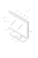
- the configuration of the display device 1 of the present technology will be described with reference to FIGS. 1 and 2.
- the display device 1 is, for example, a device such as a television device or a monitor device that displays images or images.
- the display device 1 includes a display unit 2 having a substantially rectangular shape, a support unit 3 attached to the rear surface portion of the display unit 2 and extending in the vertical direction, and a display unit 2 and a support unit 3 to which a lower end portion of the support unit 3 is attached. It is provided with a pedestal 4 having a horizontally flat shape in order to stabilize the posture of the pedestal.
- the front-back direction will be described with the user side viewing the image (image) displayed on the display device 1 as the front. Further, the direction of gravity may be described as the vertical direction, and the horizontal direction may be described as the horizontal direction. As for the left-right direction, the direction seen from the back side of the display device 1 shall be used.
- the "first direction”, “second direction”, and “third direction” referred to in the claims are the above-mentioned vertical direction, horizontal direction, and front-rear direction, respectively.
- these directions correspond to the opening directions of the intake / exhaust holes described later.
- the first direction is the vertical direction.
- the first direction is the front-rear direction
- the second direction is the left-right direction
- the third direction is the up-down direction. It should be noted that these directions are for convenience of explanation only, and are not limited to these directions regarding the implementation of the present technology.
- the display unit 2 has an outer housing portion 5 in which each part such as an electronic circuit for displaying an image or the like is housed and has an opening opened in front, and an opening of the outer housing portion 5 on which an image or the like is displayed. It is provided with a display panel 6 arranged so that an image or the like can be seen from the front through the display panel 6.
- the outer housing portion 5 includes, for example, a bezel 7 formed as a front portion, a back cover 8 formed as a rear portion and located behind the display panel 6, and various controls (not shown).
- the bezel 7 has an upper surface portion 9 that faces in the vertical direction and extends in the left-right direction, and a pair of side surface portions 10 and 10 that are continuous in the left and right ends of the upper surface portion 9 and extend in the vertical direction.
- a lower surface portion 11 having both end portions continuous with the lower end portions of the pair of side surface portions 10 and 10 and a frame-shaped portion 12 formed in a frame shape facing the front and rear are provided.
- the outer peripheral portion of the frame-shaped portion 12 is continuous with the front end portions of the upper surface portion 9, the side surface portions 10, 10 and the lower surface portion 11.
- the back cover 8 is a resin member formed in a plate shape facing forward and backward by injection molding, and is attached to the rear end portion of the bezel 7 from the rear.
- the back cover 8 is provided with an intake hole for taking in air into the internal space and an exhaust hole for discharging air from the internal space.
- the heat discharged from the substrate or the like arranged inside the display unit 2 is cooled by these intake holes and exhaust holes.
- These intake holes and exhaust holes will be collectively referred to as intake / exhaust holes 13.
- a plurality of intake / exhaust holes 13 are provided in the back cover 8 as holes opened rearward, holes opened downward, holes opened upward, and holes opened laterally. Alternatively, not only the intake / exhaust holes 13 opened in these directions but also the intake / exhaust holes 13 opened in diagonal directions may be used.
- the portion where the plurality of intake / exhaust holes 13 are formed is provided in a lattice shape.
- the intake / exhaust holes 13 may be provided in the bezel 7.
- the intake / exhaust holes 13 shown in FIG. 2 exemplify those formed as holes that open rearward in the back cover 8 and those formed as holes that open downward in the lower surface portion 11 of the bezel 7.
- the intake / exhaust holes 13 opened behind the back cover 8 will be described.
- Various shapes of the plurality of intake / exhaust holes 13 can be considered, but in this example, the intake / exhaust holes 13 having an elongated shape in the vertical direction are taken as an example.
- the display panel 6 has a laminated structure composed of a diffusion plate, an optical sheet, a wiring layer, and the like.
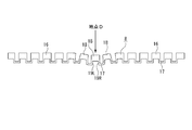
- the back cover 8 has a predetermined portion including a central portion 14 in which a plurality of intake / exhaust holes 13 are formed and an outer peripheral portion 15 as other portions.
- a portion of the outer peripheral portion 15 other than the outermost edge portion 15a includes a plurality of straight line portions 16 extending in the vertical direction and separated from each other in the horizontal direction, and a connecting portion 17 located between the straight line portions 16. .. A recess opened rearward is formed between the adjacent straight portions 16 and 16.
- the straight portion 16 includes a base portion 18 having a substantially rectangular parallelepiped shape extending in the vertical direction and a pair of projecting portions 19 and 19 having a substantially rectangular parallelepiped shape extending forward from both left and right ends of the base portion 18 and extending in the vertical direction.
- the protruding portion 19 protruding from the left end of the base 18 is referred to as a protruding portion 19L
- the protruding portion 19 protruding from the right end is referred to as a protruding portion 19R.
- the left and right protruding portions are simply described as the protruding portions 19.
- the left and right ends of the connecting portion 17 are continuous with the tip portion 20 of the protruding portion 19R of the straight portion 16 and the tip portion 20 of the protruding portion 19L of the adjacent straight portion 16.
- the rear surface of the base 18 is formed as a part of the outer surface 21 of the display device 1.
- the outer surface 21 is subjected to, for example, a surface treatment for eliminating unevenness to make it smooth, a textured treatment for forming unevenness, and the like.
- the outer surface 21 is also a portion to which an impact is applied in the impact test. Further, the outer surface 21 is regarded as one of the parts to which an impact by a user or the like is easily applied after commercialization.
- the back cover 8 has an uneven horizontal cross-sectional shape (bellows shape) due to the straight portion 16 and the connecting portion 17.
- the adjacent bases 18 and 18 approach each other and a pair of protrusions of the straight portion 16
- Each part of the back cover 8 is deformed so that the gap between the parts 19L and 19R is widened.
- the central portion 14 of the back cover 8 includes a plurality of straight portions 16 provided apart from each other in the left-right direction, and a plurality of connecting portions 22 provided apart from each other in the vertical direction. That is, a plurality of connecting portions 22 and 22 are provided between the two adjacent straight portions 16 and 16, so that the strength of the straight portions 16 is improved.
- the connecting portion 22 has the same shape as the connecting portion 17 in the horizontal cross section. That is, the connecting portion 22 has a rectangular parallelepiped shape extending in the left-right direction, and both left and right ends are continuous with the tip portion 20 of the protruding portion 19L of the straight portion 16 adjacent to the tip portion 20 of the protruding portion 19R of the straight portion 16, respectively. Has been done.
- the plurality of connecting portions 22 are provided apart from each other in the vertical direction.
- a space surrounded by straight portions 16 and 16 adjacent to each other in the left-right direction and connecting portions 22 and 22 adjacent to each other in the vertical direction is formed as intake / exhaust holes 13.
- the intake / exhaust holes 13 can release heat generated from an electronic substrate or the like arranged inside the outer housing portion 5 to the outside. Therefore, good heat dissipation in the display device 1 can be ensured.
- the space surrounded by the straight portions 16 and 16 adjacent to each other in the left-right direction, the ends of the connecting portions 17, and the connecting portion 22 is also referred to as an intake / exhaust hole 13.
- the thickness of the base 18 in the front-rear direction is defined as the thickness t1.
- the thickness of the connecting portion 22 in the front-rear direction is defined as the thickness t2.
- the thickness of the protruding portion 19 in the left-right direction is defined as the thickness t3.
- the pitch width of the connecting portions 22 and 22 in the vertical direction is defined as the pitch width a.
- the length of the connecting portion 22 in the left-right direction is defined as the length b.
- the thickness t1 is larger than the thickness t2 and the thickness t3. Further, the thickness t2 and the thickness t3 have the same size. Further, the pitch width a is larger than the length b. The conditions under which these thicknesses and lengths should be satisfied will be described later.
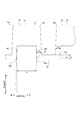
- back cover molding process in injection molding As described above, the back cover 8 is formed by injection molding using a molten resin. The process of forming each part of the back cover 8 by injection molding will be described below in chronological order (see FIGS. 8 to 15).
- FIG. 8 is a diagram showing a state in which the molten resin PL has flowed in from the inflow position E in order to form the illustrated portion of the back cover 8.
- the inflow position E is, for example, the portion shown in FIG. 8 that is closest to the gate (not shown).
- the inflow position E shown in FIG. 8 is just an example, and can be arbitrarily set depending on the position of the gate provided on the back cover 8. Further, the number of inflow positions E does not have to be one, and a plurality of inflow positions E may be provided.
- the position of the gate when the back cover 8 is formed by injection molding may be provided at any place. Further, the number of gates may be one or a plurality.
- the molten resin PL is flowed ahead of the space forming the straight portion 16B in the space forming the straight portion 16A closer to the inflow position E.
- the thickness t1 of the base 18 in the front-rear direction is larger than the thickness t3 of the protrusion 19 in the left-right direction. Therefore, the speed at which the molten resin PL flows in the front-rear direction in the space where the protrusion 19 is formed is faster than the speed at which the molten resin PL flows in the vertical direction in the space where the base 18 is formed. As a result, there is a state in which the molten resin has flowed into the base 18 and the molten resin has not flowed into the protruding portion 19. Therefore, the time required for the molten resin PL to reach the space forming the connecting portion 22 can be delayed, and the weld line W can be easily formed in the connecting portion 22.
- the molten resin PL is flowed from the space forming the straight line portion 16A to the space forming the connecting portion 22 through the space forming the protruding portion 19R, and is straight. It is flowed from the space forming the base 18 of the portion 16B toward the space forming the protruding portion 19L.
- the molten resin PL is flowed from the space forming the straight portion 16A to the space forming the connecting portion 22, and also forms the connecting portion 22 from the space forming the protruding portion 19L. It is flowed toward the space to be used.
- the molten resin PLs are merged in the space forming the connecting portion 22. Therefore, the weld line W of the molten resin PL is formed in the space forming the connecting portion 22.
- the thickness t1 of the base portion 18 in the front-rear direction is larger than the thickness t2 of the connecting portion 22 in the front-rear direction. Therefore, the speed at which the molten resin PL flows in the left-right direction in the space forming the connecting portion 22 (see FIGS. 13 and 15) is the speed at which the molten resin PL flows in the vertical direction in the space forming the base portion 18 (FIGS. 12 and 14). See) is slower than. Therefore, the weld line W can be easily formed on the connecting portion 22.
- the thickness t2 of the connecting portion 22 in the front-rear direction and the thickness t3 of the protruding portion 19 in the left-right direction may be the same.
- the strength of the reduced thickness portion is reduced, and breakage or cracking is likely to occur.
- the connecting portion 22 and the protruding portion 19 have a certain thickness as compared with the case where only one of the thicknesses t2 and t3 is reduced. be able to. Therefore, the flow rate of the molten resin PL when forming the protruding portion 19 and the connecting portion 22 can be slowed down while ensuring the strength of the protruding portion 19 and the connecting portion 22, and the durability of the back cover 8 can be improved. Can be done.
- the base portion 18 is located on the outer surface side (rear side) of the connecting portion 22.
- the connecting portion 22 in which the weld line W is likely to be formed is located closer to the internal space side of the display device 1 than the straight portion 16. Therefore, since it is difficult for an impact to be applied to the connecting portion 22 on which the weld line W is likely to be formed, damage or cracking due to the weld line W is unlikely to occur, and the durability of the back cover 8 can be improved.
- the base portion 18 is the outer surface 21 of the display device 1, an impact may be applied to the base portion 18 in the impact test. In such a case, since the weld line W is not formed on the base 18, it is easy to pass the impact test and no countermeasure is required. Therefore, it is possible to suppress the occurrence of unnecessary man-hours.
- the flow rate of the molten resin PL during injection molding depends on the magnitude of the pressure loss generated when the molten resin PL flows inside the mold. Specifically, the larger the pressure loss, the lower the flow velocity.
- the pressure loss ⁇ P is calculated by the following equation (1).
- ⁇ represents the viscosity of the molten resin PL.
- L indicates the flow distance.
- Q indicates the flow rate of the molten resin PL.
- w indicates the width of the flow path through which the molten resin PL flows.
- t indicates the thickness of the flow path.
- the molten resin PL forming the straight portion 16 (straight portion 16A in FIG. 9) forms the adjacent straight portion 22 before the connecting portion 22 is formed. It is required that the molten resin PL flowing through 16 (straight line portion 16B in FIG. 9) finishes forming the base portion 18.
- the time for forming the base portion 18 of the straight line portion 16 over the pitch width a needs to be shorter than the time for forming the connecting portion 22 over the length b.
- the pressure loss ⁇ P1 of the molten resin PL when the base portion 18 of the straight portion 16 is formed over the pitch width a can be expressed by the following equation (2) (see FIG. 16).
- the pressure loss ⁇ P2 when the molten resin PL flows from one end to the other end of the connecting portion 22 can be expressed by the following equation (3) (see FIG. 16).
- the connecting portion 22 is connected from the base portion 18 of the adjacent straight portions 16.
- the molten resin PL flows into the. Therefore, since the weld line W is not formed on the straight portion 16, the strength of the straight portion 16 can be improved.
- variable t1 is the thickness of the base 18 in the front-rear direction, and is naturally determined by the design in consideration of the strength and weight of the back cover 8.
- value of the variable a is the pitch width in the vertical direction of the connecting portions 22 and 22, and is naturally determined in consideration of the size of the intake / exhaust holes 13.
- value of the variable b is the length of the connecting portion 22 in the left-right direction, and is naturally determined in consideration of the size of the intake / exhaust holes 13.
- the value of the variable t2 is derived from the equation (4) as a value less than a predetermined value based on the values of the variables t1, a, and b.
- variable t2 In order to form the weld line W on the connecting portion 22, the variable t2 needs to be less than a predetermined value in order to satisfy the equation (4), but on the other hand, considering the durability of the back cover 8 and the like, the connecting portion The thickness t2 in the front-rear direction of 22 cannot be set to an excessively small value, and it is desirable that the variable t2 be made as large as possible.
- the conditions for increasing the value of the thickness t2 will be described below.
- the weld line W is formed on the connecting portion 22 in order to secure the high strength of the back cover 8, but the weld line 19 or the connecting portion 22 which is a portion other than the base 18 is welded. It is also permissible for the line W to be formed, and even when the weld line W is formed on the protruding portion 19, it is possible to secure sufficient strength of the back cover 8, and the weld line W is formed on the protruding portion 19.
- the value of the variable t2 can be increased as follows.
- the pressure loss of the molten resin PL when forming the protruding portion 19 of the straight portion 16 and the pressure of the molten resin PL when forming the connecting portion 22 The total value of the loss ⁇ P2 may be larger than the pressure loss ⁇ P1.
- a path through which the molten resin PL flows from the space forming the protruding portion 19R of the straight portion 16A through the space forming the connecting portion 22 to the space forming the protruding portion 19L of the straight portion 16B is provided.
- the pressure loss ⁇ P3 of the molten resin PL flowing in the path G may be larger than the pressure loss ⁇ P1.
- the strength of the reduced thickness portion may be excessively reduced. It is desirable that the thickness t2 of the connecting portion 22 in the front-rear direction and the thickness t3 of the protruding portion 19 in the left-right direction be the same.
- the pressure loss ⁇ P3 when the thickness t2 and the thickness t3 are the same value is expressed by the following equation.
- Equation (7) indicates that (t1 / t2) may have a smaller value than Equation (4). Therefore, it is possible to make t2 a larger value than the equation (4) by the equation (7).
- the thickness t2 of the protruding portion 19 and the connecting portion 22 can be made thicker, so that the strength of the protruding portion 19 and the connecting portion 22 can be improved.
- the molten resin PL when forming the base portion 18 of the straight line portion 16A forms the projecting portion 19R and the connecting portion 22, and then the straight lines adjacent to each other before forming the projecting portion 19L of the adjacent straight line portion 16B.
- the molten resin PL flows from the base 18 of the portion 16B into the protruding portion 19L.
- the molten resin PL that flows from the space forming the adjacent straight portions 16 to the space forming the connecting portion 22 located between them is merged at the connecting portion 22 or the protruding portion 19. NS. Therefore, since the weld line W is not formed on the straight portion 16, the strength of the straight portion 16 can be further improved.
- the pitch width a of the connecting portion 22 is made larger than the length b of the connecting portion 22, the space surrounded by the straight portion 16 and the connecting portion 22 is formed as an elongated intake / exhaust hole 13. Therefore, it is possible to suppress the intrusion of fingers, foreign substances, etc. into the inside of the display device 1 from the elongated intake / exhaust holes 13.
- condition of the thickness t2 can be relaxed by using a variable other than the thickness t2 as a constant
- the condition of the variable other than the thickness t2 can be relaxed by changing the combination of the variables to be a constant.
- FIG. 18 shows a dimensional example of each portion of the straight portion 16 and the connecting portion 22.
- the left and right ends of the rear end of the base 18 are formed as corners 18a, respectively.
- the inner ends of the tip portions 20 and 20 of the protrusions 19L and 19R are formed as internal angle portions 20a and 20a, respectively.
- the distance d between the protruding portion 19L protruding from one base 18 and the portion continuous with the base 18 in the protruding portion 19R is 2.3 times or more the thickness t2 of the connecting portion 22 and the thickness t3 of the protruding portion 19. It is desirable to be done.
- the thickness t2 of the connecting portion 22 and the thickness t3 of the protruding portion 19 it is difficult to form the thickness t2 of the connecting portion 22 and the thickness t3 of the protruding portion 19 to be less than 1 mm in view of ease of injection molding. Therefore, for example, assuming that the thickness t2 of the connecting portion 22 and the thickness t3 of the protruding portion 19 are 1 mm, it is desirable that the distance d be 2.1 mm or more. As a result, the speed of the molten resin when forming the projecting portion 19 and the connecting portion 22 is sufficiently slower than the speed of the molten resin PL when forming the base portion 18, and the weld line W is formed in a portion other than the base portion 18. It becomes easier to do.
- corner portion 18a and the inner corner portion 20a are subjected to R chamfering in order to prevent chipping and the like. It is desirable that the corner portion 18a is subjected to, for example, R chamfering with a radius of 0.5 mm to 1 mm, and the inner corner portion 20a is subjected to, for example, R chamfering with a radius of 0.3 mm.
- the corners at both ends of the rear end of the connecting portion 22 are set to 180 degrees or more, and chipping or the like is unlikely to occur, so that it is not necessary to perform R chamfering.
- the corners provided at the continuous portion of the base portion 18 and the protruding portion 19 are set to 180 degrees or more, it is not necessary to perform R chamfering.
- the angle r formed by the protruding portion 19 in the extending direction and the front-rear direction is larger than 0 degrees.
- the angle r is, for example, 0.5 degrees or more.
- the maximum value of the pitch width a in the vertical direction of the connecting portion 22 is set to a predetermined value or less so that the strength of the straight portion 16 does not decrease. Further, from the viewpoint of heat exhaust efficiency, it is desirable that the pitch width a is set to a predetermined value or more. For example, the pitch width is 3 mm or more and 30 mm or less.
- the length b of the connecting portion 22 in the left-right direction be set to a predetermined value or less in order to prevent fingers or the like from entering through the intake / exhaust holes 13. Further, from the viewpoint of heat exhaust efficiency, it is desirable that the length b is set to a predetermined value or more.
- the length b is 1 mm or more and 30 mm or less.
- the thickness t1 of the base 18 in the front-rear direction is preferably set to a predetermined value or more from the viewpoint of ease of injection molding. Further, it is desirable that the thickness t1 is set to a predetermined value or less from the viewpoint of weight and cost. For example, the thickness t1 is 0.5 mm or more and 4 mm or less.
- the thickness t2 of the connecting portion 22 in the front-rear direction is preferably set to a predetermined value or more from the viewpoint of ease of injection molding. Further, it is desirable that the thickness t2 is set to be equal to or less than a predetermined position from the viewpoint of weight and cost. For example, the thickness t2 is 0.5 mm or more and 4 mm or less.
- the relationship between the thicknesses t1 and t2 is important. That is, it is desirable that the above equations (4) and (7) are set so as to satisfy the conditions that the thickness t1 and the thickness t2 are 0.5 mm or more and 4 mm or less, respectively.
- the straight portion 16 in this example is a straight portion 16C in which an inclined surface is formed on a part of the base portion 18. Specifically, it will be described with reference to FIG.
- FIG. 19 shows one straight line portion 16C and a plurality of connecting portions 22 extending in the left-right direction from the straight line portion 16C. Further, FIG. 19 shows a cross-sectional view of the straight line portion 16C and the connecting portion 22, and an end view of a plane H orthogonal to the vertical direction as an end view of a portion where the connecting portion 22 is not located.
- the straight portion 16C has a base portion 18C and protrusions 19L and 19R.
- the base portion 18C is composed of a projecting portion 24 formed as a rear portion and a base portion 25 formed as a portion in front of the projecting portion 24.
- the projecting portion 24 has a rectangular horizontal cross-sectional shape
- the base portion 25 has an equilateral trapezoidal horizontal cross-sectional shape and is wider in the left-right direction than the projecting portion 24.
- the outer surfaces of the base portion 25 in the left-right direction are formed as inclined surfaces 26, 26 that approach each other as they approach the protruding portion 24.
- the angle of the corner portion 27 of the portion where the rear surface of the base portion 25 and the inclined surface 26 are continuous is made larger than the right angle, and the corner portion 27 is less likely to be chipped. Be crushed.
- the molten resin PL is less likely to flow from the base portion 18C of the straight portion 16C into the protruding portions 19L and 19R. That is, the time required for the molten resin PL to reach the connecting portion 22 is lengthened, and the weld line W is more likely to be formed in the connecting portion 22. Further, in the mold release process of injection molding, the molded product and the mold can be easily separated, and the work efficiency can be improved.
- the inclined surface 26 is provided only in the portion of the straight line portion 16 that is continuous with the connecting portion 22 and the portion in the vicinity thereof, and as shown in the end view of FIG. 19, the inclined surface 26 is provided between the adjacent connecting portions 22, 22. It is not formed in the part.
- the portion near the connecting portion 22 is formed as a wide portion 28 having a wide width in the left-right direction, and the other portion is formed as a narrow portion 29 having a width narrower in the left-right direction than the wide portion 28. Has been done.
- the narrow portion 29 is formed as compared with the case where the narrow portion 29 is not formed. Drift velocity is slowed down. Therefore, the time until the molten resin PL flows into the wide portion 28 formed in the vicinity of the connecting portion 22 is lengthened, and the possibility that the weld line W is formed in the connecting portion 22 can be increased.
- the edge portion of the intake / exhaust hole 13 may be formed as the connecting portion 22 in the connecting portion 17.
- all the intake / exhaust holes 13 are formed by a set of straight portions 16 and 16 adjacent to each other in the left-right direction and a set of connecting portions 22 and 22 adjacent to each other in the vertical direction. That is, the various actions and effects described above and described later also apply to the intake / exhaust holes 13'formed by the pair of straight portions 16, 16 and one end portion in the vertical direction of the connecting portion 17 and the connecting portion 22. Become.
- the display device 1 is provided with the back cover 8 having the intake / exhaust holes 13 formed therein.
- the intake / exhaust holes are provided in the back cover, the side cover, etc. of the outer housing of other electronic devices and the like. 13 may be formed.
- a personal computer is provided with various substrates or devices such as a motherboard arranged in an internal space and an outer housing
- intake / exhaust holes 13 having the above-mentioned characteristics are formed on the back surface and side surfaces of the outer housing. You may.
- the holes formed by the straight line portion and the connecting portion are not limited to the intake / exhaust holes, and the present technology can be applied to various structures formed in a grid pattern by injection molding in the display device 1.
- the connecting portion 17 is formed on the outer peripheral portion 15 of the back cover 8 is shown above, the present technology can be applied to a configuration in which the connecting portion 17 is not formed on the outer peripheral portion 15. be.
- the three directions orthogonal to each other are the first direction (vertical direction), the second direction (horizontal direction), and the third direction (front-back direction), respectively.
- a plurality of straight lines 16 (16A, 16B, 16C) extending in the first direction (vertical direction) and separated from each other in the second direction (horizontal direction), and a second direction (horizontal direction).
- a connecting portion 22 for connecting a part of each of two adjacent straight portions 16 (16A, 16B, 16C) is provided.
- the straight portion 16 (16A, 16B, 16C) and the connecting portion 22 are integrally formed by injection molding, and the straight portion 16 (16A, 16B, 16C) is a base portion 18 (18C) extending in the first direction (vertical direction). ), And a pair of projecting portions 19 (19L, 19R) projecting from both ends in the second direction (left-right direction) of the base portion 18 (18C) in the third direction (front-rear direction), and the connecting portion 22. Is continuous with each tip portion 20 of the protruding portion 19 (19L, 19R) of the two straight portions 16 (16A, 16B, 16C) whose both ends are adjacent to each other.
- the straight portion 16 (16A, 16B, 16C) and the continuous portion of the connecting portion 22 have a zigzag shape (bellows shape) in which the portions having a U-shaped cross section are alternately combined, the base portion 18 (18C) is formed. ), Tensile stress is unlikely to occur in the connecting portion 22, and cracks and breaks are unlikely to occur in the connecting portion 22. Therefore, the number of back covers 8 that fall off due to the impact test is reduced, and no countermeasure is required.
- the present technology can also adopt the following configurations.
- the three directions orthogonal to each other are the first direction, the second direction, and the third direction, respectively.
- a plurality of straight portions extending in the first direction and separated from each other in the second direction,
- a connecting portion for connecting a part of each of the two adjacent straight portions in the second direction is provided.
- the straight portion and the connecting portion are integrally formed by injection molding.
- the straight line portion has a base portion extending in the first direction and a pair of projecting portions projecting from both ends of the base portion in the second direction in the third direction.
- the connecting portion is a display device whose both ends are continuous with each tip of the protruding portion in the two adjacent straight portions.
Landscapes
- Engineering & Computer Science (AREA)
- Microelectronics & Electronic Packaging (AREA)
- Physics & Mathematics (AREA)
- Theoretical Computer Science (AREA)
- Thermal Sciences (AREA)
- General Engineering & Computer Science (AREA)
- General Physics & Mathematics (AREA)
- Human Computer Interaction (AREA)
- Manufacturing & Machinery (AREA)
- Mechanical Engineering (AREA)
- Signal Processing (AREA)
- Multimedia (AREA)
- Computer Hardware Design (AREA)
- Moulds For Moulding Plastics Or The Like (AREA)
- Devices For Indicating Variable Information By Combining Individual Elements (AREA)
- Injection Moulding Of Plastics Or The Like (AREA)
- Casings For Electric Apparatus (AREA)
- Cooling Or The Like Of Electrical Apparatus (AREA)
Priority Applications (8)
| Application Number | Priority Date | Filing Date | Title |
|---|---|---|---|
| CN202511084613.2A CN120877604A (zh) | 2020-03-31 | 2021-02-16 | 显示装置 |
| CN202180024169.9A CN115380317B (zh) | 2020-03-31 | 2021-02-16 | 显示装置 |
| EP21781373.2A EP4129619B1 (en) | 2020-03-31 | 2021-02-16 | Display device |
| JP2022511639A JP7706441B2 (ja) | 2020-03-31 | 2021-02-16 | 表示装置 |
| EP25163720.3A EP4559656A3 (en) | 2020-03-31 | 2021-02-16 | Display device |
| US17/910,177 US12200879B2 (en) | 2020-03-31 | 2021-02-16 | Display device |
| US18/968,158 US20250176117A1 (en) | 2020-03-31 | 2024-12-04 | Display device |
| JP2025111547A JP2025129279A (ja) | 2020-03-31 | 2025-07-01 | 表示装置 |
Applications Claiming Priority (2)
| Application Number | Priority Date | Filing Date | Title |
|---|---|---|---|
| JP2020-065174 | 2020-03-31 | ||
| JP2020065174 | 2020-03-31 |
Related Child Applications (2)
| Application Number | Title | Priority Date | Filing Date |
|---|---|---|---|
| US17/910,177 A-371-Of-International US12200879B2 (en) | 2020-03-31 | 2021-02-16 | Display device |
| US18/968,158 Continuation US20250176117A1 (en) | 2020-03-31 | 2024-12-04 | Display device |
Publications (1)
| Publication Number | Publication Date |
|---|---|
| WO2021199743A1 true WO2021199743A1 (ja) | 2021-10-07 |
Family
ID=77930261
Family Applications (1)
| Application Number | Title | Priority Date | Filing Date |
|---|---|---|---|
| PCT/JP2021/005733 Ceased WO2021199743A1 (ja) | 2020-03-31 | 2021-02-16 | 表示装置 |
Country Status (5)
| Country | Link |
|---|---|
| US (2) | US12200879B2 (https=) |
| EP (2) | EP4129619B1 (https=) |
| JP (2) | JP7706441B2 (https=) |
| CN (2) | CN120877604A (https=) |
| WO (1) | WO2021199743A1 (https=) |
Citations (6)
| Publication number | Priority date | Publication date | Assignee | Title |
|---|---|---|---|---|
| JPS4991204U (https=) * | 1972-11-27 | 1974-08-07 | ||
| US20050157457A1 (en) * | 2004-01-19 | 2005-07-21 | Kwey-Hyun Kim | Display apparatus and method of making the same |
| US20070127208A1 (en) * | 2005-12-05 | 2007-06-07 | Dong-Hyok Shin | Heat-radiating structure and plasma display device including the same |
| JP2011095772A (ja) | 2011-01-21 | 2011-05-12 | Nec Infrontia Corp | 画像表示装置 |
| JP2013134418A (ja) * | 2011-12-27 | 2013-07-08 | Sanyo Electric Co Ltd | 表示装置 |
| JP2014228802A (ja) * | 2013-05-24 | 2014-12-08 | 船井電機株式会社 | 表示装置 |
Family Cites Families (16)
| Publication number | Priority date | Publication date | Assignee | Title |
|---|---|---|---|---|
| US5547272A (en) * | 1995-04-24 | 1996-08-20 | At&T Global Information Solutions Company | Modular cabinet bezel |
| US6373697B1 (en) * | 1999-06-28 | 2002-04-16 | Sun Microsystems, Inc. | Computer system housing and configuration |
| US6477055B1 (en) * | 2000-10-18 | 2002-11-05 | Compaq Information Technologies Group, L.P. | System for reducing airflow obstruction in a low profile processor-based device |
| JP2003215702A (ja) * | 2002-01-23 | 2003-07-30 | Seiko Epson Corp | プロジェクタ |
| US6826057B1 (en) * | 2002-09-24 | 2004-11-30 | Emc Corporation | Electronic cabinet panel with improved latching mechanism |
| JP2006106272A (ja) * | 2004-10-04 | 2006-04-20 | Sony Corp | 表示装置 |
| JP4808973B2 (ja) * | 2005-02-02 | 2011-11-02 | パナソニック株式会社 | 平面型表示装置 |
| JP3115625U (ja) * | 2005-08-09 | 2005-11-10 | 船井電機株式会社 | 放熱孔を有する電気機器キャビネット |
| EP4270935A3 (en) * | 2007-09-28 | 2024-01-24 | Maxell, Ltd. | Image displaying apparatus |
| JP2009098310A (ja) * | 2007-10-15 | 2009-05-07 | Hitachi Displays Ltd | 液晶表示装置 |
| US20120236499A1 (en) * | 2009-12-03 | 2012-09-20 | Panasonic Corporation | Radiation unit of electronic device and electronic device using same |
| US20130163200A1 (en) * | 2011-12-27 | 2013-06-27 | Sanyo Electric Co., Ltd. | Display Device |
| JP2013247641A (ja) * | 2012-05-29 | 2013-12-09 | Panasonic Corp | 画像表示装置 |
| EP3088942B1 (en) * | 2014-06-18 | 2021-03-03 | Keewin Display Co.,Ltd. | Display module heat dissipation structure |
| KR102560667B1 (ko) * | 2018-07-23 | 2023-07-27 | 엘지전자 주식회사 | 디스플레이 디바이스 |
| CN209840038U (zh) * | 2019-07-06 | 2019-12-24 | 中山市洲和照明电器有限公司 | 一种通风结构的冷锻一体成型轨道灯散热筒 |
-
2021
- 2021-02-16 CN CN202511084613.2A patent/CN120877604A/zh active Pending
- 2021-02-16 EP EP21781373.2A patent/EP4129619B1/en active Active
- 2021-02-16 CN CN202180024169.9A patent/CN115380317B/zh active Active
- 2021-02-16 WO PCT/JP2021/005733 patent/WO2021199743A1/ja not_active Ceased
- 2021-02-16 EP EP25163720.3A patent/EP4559656A3/en active Pending
- 2021-02-16 US US17/910,177 patent/US12200879B2/en active Active
- 2021-02-16 JP JP2022511639A patent/JP7706441B2/ja active Active
-
2024
- 2024-12-04 US US18/968,158 patent/US20250176117A1/en active Pending
-
2025
- 2025-07-01 JP JP2025111547A patent/JP2025129279A/ja active Pending
Patent Citations (6)
| Publication number | Priority date | Publication date | Assignee | Title |
|---|---|---|---|---|
| JPS4991204U (https=) * | 1972-11-27 | 1974-08-07 | ||
| US20050157457A1 (en) * | 2004-01-19 | 2005-07-21 | Kwey-Hyun Kim | Display apparatus and method of making the same |
| US20070127208A1 (en) * | 2005-12-05 | 2007-06-07 | Dong-Hyok Shin | Heat-radiating structure and plasma display device including the same |
| JP2011095772A (ja) | 2011-01-21 | 2011-05-12 | Nec Infrontia Corp | 画像表示装置 |
| JP2013134418A (ja) * | 2011-12-27 | 2013-07-08 | Sanyo Electric Co Ltd | 表示装置 |
| JP2014228802A (ja) * | 2013-05-24 | 2014-12-08 | 船井電機株式会社 | 表示装置 |
Also Published As
| Publication number | Publication date |
|---|---|
| JP7706441B2 (ja) | 2025-07-11 |
| EP4129619A1 (en) | 2023-02-08 |
| EP4559656A3 (en) | 2025-11-05 |
| US20230100766A1 (en) | 2023-03-30 |
| EP4129619A4 (en) | 2023-09-13 |
| EP4129619B1 (en) | 2025-04-09 |
| JPWO2021199743A1 (https=) | 2021-10-07 |
| CN115380317A (zh) | 2022-11-22 |
| US20250176117A1 (en) | 2025-05-29 |
| CN115380317B (zh) | 2025-08-22 |
| CN120877604A (zh) | 2025-10-31 |
| JP2025129279A (ja) | 2025-09-04 |
| US12200879B2 (en) | 2025-01-14 |
| EP4559656A2 (en) | 2025-05-28 |
Similar Documents
| Publication | Publication Date | Title |
|---|---|---|
| US9974207B2 (en) | Electronic apparatus | |
| TWI422319B (zh) | 導風罩及電子裝置 | |
| CN104819438A (zh) | 背板、胶铁一体结构、背光模组和显示装置 | |
| JP2007047998A (ja) | 電子部品冷却構造及び情報処理装置 | |
| WO2021129609A1 (zh) | Led箱体、led箱体的制造方法及led显示屏 | |
| TWI669049B (zh) | 電子機器 | |
| KR101419636B1 (ko) | 히트 싱크 및 그 제조 방법 | |
| CN116234362A (zh) | 显示模组和显示装置 | |
| WO2021199743A1 (ja) | 表示装置 | |
| US20140193999A1 (en) | Connector and integrally molded product | |
| CN103687449B (zh) | 电子设备和数据中心 | |
| CN118012239A (zh) | 电子设备的冷却装置 | |
| WO2020098380A1 (zh) | 背板、背光模组及显示装置 | |
| CN104185356B (zh) | 光模块散热系统 | |
| US20160357058A1 (en) | Curved display device | |
| TW201401989A (zh) | 伺服器機架 | |
| JP7762640B2 (ja) | 電子機器の冷却装置 | |
| CN113311529B (zh) | 导光板及背光模组 | |
| KR102168824B1 (ko) | 전자 기기 | |
| CN102414867A (zh) | 电池组 | |
| JP2011023441A (ja) | 通気部材、筐体、電子機器および表示装置 | |
| JP2010016248A (ja) | 電子機器の冷却装置 | |
| CN115851143B (zh) | 贴合结构 | |
| JP2020096019A (ja) | 電子装置 | |
| KR101375578B1 (ko) | 멀티 디스플레이 |
Legal Events
| Date | Code | Title | Description |
|---|---|---|---|
| 121 | Ep: the epo has been informed by wipo that ep was designated in this application |
Ref document number: 21781373 Country of ref document: EP Kind code of ref document: A1 |
|
| ENP | Entry into the national phase |
Ref document number: 2022511639 Country of ref document: JP Kind code of ref document: A |
|
| NENP | Non-entry into the national phase |
Ref country code: DE |
|
| ENP | Entry into the national phase |
Ref document number: 2021781373 Country of ref document: EP Effective date: 20221031 |
|
| WWG | Wipo information: grant in national office |
Ref document number: 2021781373 Country of ref document: EP |
|
| WWG | Wipo information: grant in national office |
Ref document number: 202180024169.9 Country of ref document: CN |