EP4129619B1 - Display device - Google Patents
Display device Download PDFInfo
- Publication number
- EP4129619B1 EP4129619B1 EP21781373.2A EP21781373A EP4129619B1 EP 4129619 B1 EP4129619 B1 EP 4129619B1 EP 21781373 A EP21781373 A EP 21781373A EP 4129619 B1 EP4129619 B1 EP 4129619B1
- Authority
- EP
- European Patent Office
- Prior art keywords
- connecting portion
- thickness
- display device
- portions
- linear
- Prior art date
- Legal status (The legal status is an assumption and is not a legal conclusion. Google has not performed a legal analysis and makes no representation as to the accuracy of the status listed.)
- Active
Links
Images


Classifications
-
- G—PHYSICS
- G09—EDUCATION; CRYPTOGRAPHY; DISPLAY; ADVERTISING; SEALS
- G09F—DISPLAYING; ADVERTISING; SIGNS; LABELS OR NAME-PLATES; SEALS
- G09F9/00—Indicating arrangements for variable information in which the information is built-up on a support by selection or combination of individual elements
-
- H—ELECTRICITY
- H05—ELECTRIC TECHNIQUES NOT OTHERWISE PROVIDED FOR
- H05K—PRINTED CIRCUITS; CASINGS OR CONSTRUCTIONAL DETAILS OF ELECTRIC APPARATUS; MANUFACTURE OF ASSEMBLAGES OF ELECTRICAL COMPONENTS
- H05K7/00—Constructional details common to different types of electric apparatus
- H05K7/20—Modifications to facilitate cooling, ventilating, or heating
- H05K7/20954—Modifications to facilitate cooling, ventilating, or heating for display panels
- H05K7/20972—Forced ventilation, e.g. on heat dissipaters coupled to components
-
- B—PERFORMING OPERATIONS; TRANSPORTING
- B29—WORKING OF PLASTICS; WORKING OF SUBSTANCES IN A PLASTIC STATE IN GENERAL
- B29C—SHAPING OR JOINING OF PLASTICS; SHAPING OF MATERIAL IN A PLASTIC STATE, NOT OTHERWISE PROVIDED FOR; AFTER-TREATMENT OF THE SHAPED PRODUCTS, e.g. REPAIRING
- B29C45/00—Injection moulding, i.e. forcing the required volume of moulding material through a nozzle into a closed mould; Apparatus therefor
- B29C45/0046—Details relating to the filling pattern or flow paths or flow characteristics of moulding material in the mould cavity
-
- G—PHYSICS
- G06—COMPUTING OR CALCULATING; COUNTING
- G06F—ELECTRIC DIGITAL DATA PROCESSING
- G06F1/00—Details not covered by groups G06F3/00 - G06F13/00 and G06F21/00
- G06F1/16—Constructional details or arrangements
- G06F1/1601—Constructional details related to the housing of computer displays, e.g. of CRT monitors, of flat displays
-
- G—PHYSICS
- G06—COMPUTING OR CALCULATING; COUNTING
- G06F—ELECTRIC DIGITAL DATA PROCESSING
- G06F1/00—Details not covered by groups G06F3/00 - G06F13/00 and G06F21/00
- G06F1/16—Constructional details or arrangements
- G06F1/20—Cooling means
-
- H—ELECTRICITY
- H04—ELECTRIC COMMUNICATION TECHNIQUE
- H04N—PICTORIAL COMMUNICATION, e.g. TELEVISION
- H04N5/00—Details of television systems
- H04N5/64—Constructional details of receivers, e.g. cabinets or dust covers
-
- H—ELECTRICITY
- H05—ELECTRIC TECHNIQUES NOT OTHERWISE PROVIDED FOR
- H05K—PRINTED CIRCUITS; CASINGS OR CONSTRUCTIONAL DETAILS OF ELECTRIC APPARATUS; MANUFACTURE OF ASSEMBLAGES OF ELECTRICAL COMPONENTS
- H05K5/00—Casings, cabinets or drawers for electric apparatus
- H05K5/02—Details
- H05K5/0213—Venting apertures; Constructional details thereof
-
- H—ELECTRICITY
- H05—ELECTRIC TECHNIQUES NOT OTHERWISE PROVIDED FOR
- H05K—PRINTED CIRCUITS; CASINGS OR CONSTRUCTIONAL DETAILS OF ELECTRIC APPARATUS; MANUFACTURE OF ASSEMBLAGES OF ELECTRICAL COMPONENTS
- H05K5/00—Casings, cabinets or drawers for electric apparatus
- H05K5/02—Details
- H05K5/0217—Mechanical details of casings
-
- H—ELECTRICITY
- H05—ELECTRIC TECHNIQUES NOT OTHERWISE PROVIDED FOR
- H05K—PRINTED CIRCUITS; CASINGS OR CONSTRUCTIONAL DETAILS OF ELECTRIC APPARATUS; MANUFACTURE OF ASSEMBLAGES OF ELECTRICAL COMPONENTS
- H05K5/00—Casings, cabinets or drawers for electric apparatus
- H05K5/02—Details
- H05K5/03—Covers
-
- H—ELECTRICITY
- H05—ELECTRIC TECHNIQUES NOT OTHERWISE PROVIDED FOR
- H05K—PRINTED CIRCUITS; CASINGS OR CONSTRUCTIONAL DETAILS OF ELECTRIC APPARATUS; MANUFACTURE OF ASSEMBLAGES OF ELECTRICAL COMPONENTS
- H05K7/00—Constructional details common to different types of electric apparatus
- H05K7/14—Mounting supporting structure in casing or on frame or rack
- H05K7/1417—Mounting supporting structure in casing or on frame or rack having securing means for mounting boards, plates or wiring boards
-
- H—ELECTRICITY
- H05—ELECTRIC TECHNIQUES NOT OTHERWISE PROVIDED FOR
- H05K—PRINTED CIRCUITS; CASINGS OR CONSTRUCTIONAL DETAILS OF ELECTRIC APPARATUS; MANUFACTURE OF ASSEMBLAGES OF ELECTRICAL COMPONENTS
- H05K7/00—Constructional details common to different types of electric apparatus
- H05K7/20—Modifications to facilitate cooling, ventilating, or heating
- H05K7/20009—Modifications to facilitate cooling, ventilating, or heating using a gaseous coolant in electronic enclosures
- H05K7/20127—Natural convection
-
- B—PERFORMING OPERATIONS; TRANSPORTING
- B29—WORKING OF PLASTICS; WORKING OF SUBSTANCES IN A PLASTIC STATE IN GENERAL
- B29L—INDEXING SCHEME ASSOCIATED WITH SUBCLASS B29C, RELATING TO PARTICULAR ARTICLES
- B29L2031/00—Other particular articles
- B29L2031/34—Electrical apparatus, e.g. sparking plugs or parts thereof
- B29L2031/3475—Displays, monitors, TV-sets, computer screens
-
- H—ELECTRICITY
- H05—ELECTRIC TECHNIQUES NOT OTHERWISE PROVIDED FOR
- H05K—PRINTED CIRCUITS; CASINGS OR CONSTRUCTIONAL DETAILS OF ELECTRIC APPARATUS; MANUFACTURE OF ASSEMBLAGES OF ELECTRICAL COMPONENTS
- H05K7/00—Constructional details common to different types of electric apparatus
- H05K7/20—Modifications to facilitate cooling, ventilating, or heating
- H05K7/20954—Modifications to facilitate cooling, ventilating, or heating for display panels
Definitions
- the present technology relates to a technology for a display device having a structure formed by injection molding.
- Some display devices typified by televisions have a structure formed by injection molding.
- a back cover which is a part of an outer casing is formed by injection molding in some cases.
- a plurality of holes for intake and exhaust of air is formed to cool heat generated inside the outer casing (see, for example, Patent Document 1).
- Such a portion having the plurality of holes is formed in a lattice shape.
- Patent Document 2 describes a heat-radiating structure and a plasma display device that incorporates this structure.
- Patent Document 2 primarily focuses on enhancing heat dissipation efficiency. It describes a heat-radiating structure featuring an uneven shape in a chassis base bed and a heat sink installed on a cover plate, facilitating heat radiation from both sides of the cover plate.
- This structure includes a signal transmission unit with an integrated circuit, a chassis supporting this unit, and a cover plate with a formed heat sink.
- Patent Document 2 addresses issues with heat dissipation in plasma display devices, particularly those with plastic chassis bases that impede effective heat radiation.
- Patent Document 3 describes a display device with a particular focus on its intake and exhaust mechanisms. It details the structure and functionality of an intake side lid body, which is integral to the device's ventilation system.
- Patent Document 3 emphasizes features like locking mechanisms, and the arrangement of intake ports to prevent the intrusion of foreign matter and water, ensuring the device's protection and efficient operation, especially in outdoor environments.
- the lattice-shaped portion is formed by injection molding, the dividing and joining of a molten resin occur. In some cases, a weld line is formed at the junction of the molten resin.
- the present technology has been made in view of such a problem, and an object thereof is to improve a strength in a portion where a hole is formed.
- a display device includes: a plurality of linear portions that, when three directions orthogonal to each other are a first direction, a second direction, and a third direction, extends in the first direction and is positioned apart from each other in the second direction; and a connecting portion that connects respective parts of two linear portions adjacent to each other in the second direction.
- the linear portion and the connecting portion are integrally formed by injection molding, the linear portion has a base extending in the first direction and a pair of protrusions protruding in the third direction from both end portions of the base in the second direction, and both end portions of the connecting portion are continuous to respective tip portions of the protrusions of the two adjacent linear portions.
- the pitch width a may be larger than the length b.
- the flow speed of the molten resin at the time of forming the protrusion is made slower than the flow speed of the molten resin at the time of forming the base of the linear portion.
- the weld line is easily formed in the connecting portion in the back cover.
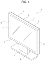
- the display device 1 is a device, such as a television device or a monitor device, on which a video or an image is displayed.
- the display device 1 includes a display unit 2 having a substantially rectangular shape, a support unit 3 attached to a rear surface portion of the display unit 2 and extending in an up-down direction, and a pedestal portion 4 to which a lower end portion of the support unit 3 is attached and which has a flat shape in a horizontal direction in order to stabilize postures of the display unit 2 and the support unit 3.
- a front-rear direction will be described with a user side viewing a video (image) shown on the display device 1 as a front side. Furthermore, in some cases, a gravity direction is described as the up-down direction, and the horizontal direction is described as a left-right direction. Note that, as the left-right direction, a direction viewed from the back surface side of the display device 1 is used.
- a "first direction”, a “second direction”, and a “third direction” in the claims are the up-down direction, the left-right direction, and the front-rear direction described above, respectively.
- these directions are set according to the opening direction of an intake and exhaust hole described later.
- the first direction is the up-down direction.
- the first direction is the front-rear direction
- the second direction is the left-right direction
- the third direction is the up-down direction.
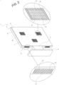
- the display unit 2 includes an outer casing portion 5 in which each unit such as an electronic circuit for displaying an image and the like is housed and which has an opening opened forward, and a display panel 6 on which the image and the like are displayed and which is disposed such that the image and the like can be seen from the front through the opening of the outer casing portion 5.
- the outer casing portion 5 includes, for example, a bezel 7 formed as a front side portion, a back cover 8 formed as a rear side portion and positioned behind the display panel 6, and various operators (not illustrated).
- the back cover 8 is a resin member which is formed in a plate shape facing the front-rear direction by injection molding, and is attached to the rear end portion of the bezel 7 from the rear side.
- a plurality of intake and exhaust holes 13 is provided as a hole opened rearward, a hole opened downward, a hole opened upward, and a hole opened sideways in the back cover 8.
- the intake and exhaust holes 13 opened in an oblique direction may be used.
- a portion where the plurality of intake and exhaust holes 13 is formed is provided in a lattice shape.
- the intake and exhaust holes 13 may be provided in the bezel 7.
- the intake and exhaust holes 13 illustrated in Fig. 2 are exemplified as holes which are formed in the back cover 8 to be opened rearward and holes which are formed in the lower surface portion 11 of the bezel 7 to be opened downward.
- the intake and exhaust holes 13 opened to the rear side of the back cover 8 will be described.
- Various shapes of the plurality of intake and exhaust holes 13 can be considered, but in this example, the intake and exhaust holes 13 having an elongated shape in the up-down direction are taken as an example.
- the display panel 6 has a laminated structure including a diffusion plate, an optical sheet, a wiring layer, and the like.
- a predetermined portion of the back cover 8 includes a central portion 14 in which the plurality of intake and exhaust holes 13 is formed and an outer peripheral portion 15 which is the other portion.
- a portion of the outer peripheral portion 15 excluding an outermost edge portion 15a includes a plurality of linear portions 16 extending in the up-down direction and positioned to be apart from each other in the left-right direction and a connection portion 17 positioned between the linear portions 16.
- a recess opened rearward is formed between the adjacent linear portions 16 and 16.
- the linear portion 16 includes a base 18 extending in the up-down direction and having a substantially rectangular parallelepiped shape, and a pair of protrusions 19 and 19 protruding forward from both left and right end portions of the base 18 and having a substantially rectangular parallelepiped shape extending in the up-down direction.
- connection portion 17 Both left and right end portions of the connection portion 17 are respectively continuous with a tip portion 20 of the protrusion 19R of the linear portion 16 and a tip portion 20 of the protrusion 19L of the linear portion 16 adjacent to each other.
- the rear surface of the base 18 is formed as a part of the outer surface 21 of the display device 1.
- the outer surface 21 is subjected to, for example, surface processing for smoothing by eliminating irregularities, emboss processing for forming irregularities, and the like. Furthermore, the outer surface 21 is also a portion to which an impact is applied in an impact test. Moreover, the outer surface 21 is one of portions to which an impact from a user or the like is likely to be applied after commercialization.
- the horizontal cross-sectional shape is formed to have an uneven shape (bellows shape) by the linear portion 16 and the connection portion 17.
- each portion of the back cover 8 is deformed such that the adjacent bases 18 and 18 approach each other and a gap between the pair of protrusions 19L and 19R of the linear portion 16 widens.
- the impact applied to the back cover 8 is absorbed by the distortion before being transmitted to the connection portion 17 and the protrusion 19, and thus a large stress is not generated in the connection portion 17 and the protrusion 19.
- the central portion 14 of the back cover 8 includes the plurality of linear portions 16 provided apart from each other in the left-right direction and a plurality of connecting portions 22 provided apart from each other in the up-down direction. That is, the plurality of connecting portions 22 and 22 is provided between two adjacent linear portions 16 and 16, and the strength of the linear portion 16 is improved.
- the connecting portion 22 has a shape similar to the connection portion 17 in the horizontal cross section. That is, the connecting portion 22 has a rectangular parallelepiped shape extending in the left-right direction, and both left and right end portions thereof are respectively continuous with the tip portion 20 of the protrusion 19R of the linear portion 16 and the tip portion 20 of the protrusion 19L of the linear portion 16 which are adjacent to each other.
- the plurality of connecting portions 22 is provided to be apart from each other in the up-down direction.
- a space surrounded by the linear portions 16 and 16 adjacent to each other in the left-right direction and the connecting portions 22 and 22 adjacent to each other in the up-down direction is formed as the intake and exhaust hole 13. Heat generated from an electronic substrate or the like disposed inside the outer casing portion 5 can be released to the outside through the intake and exhaust holes 13. Therefore, excellent heat dissipation can be secured in the display device 1.
- the thickness t1 is larger than the thickness t2 and the thickness t3. Furthermore, the thickness t2 and the thickness t3 are the same.
- the pitch width a is larger than the length b.
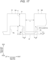
- Fig. 8 is a diagram illustrating a state where a molten resin PL flows in from an inflow position E to form the illustrated portion in the back cover 8.
- the inflow position E is, for example, a portion closest to a gate (not illustrated) in the portion illustrated in Fig. 8 .
- the inflow position E illustrated in Fig. 8 is merely an example, and can be arbitrarily set according to the position of the gate provided in the back cover 8.
- the number of inflow positions E is not necessarily one, and a plurality of inflow positions E may be provided.
- the thickness t1 of the base 18 in the front-rear direction is larger than the thickness t3 of the protrusion 19 in the left-right direction. Therefore, a speed at which the molten resin PL flows in the front-rear direction in a space where the protrusion 19 is made faster than a speed at which the molten resin PL flows in the up-down direction in a space where the base 18 is formed. Therefore, there is a state where the molten resin flows into the base 18 and the molten resin does not flow into the protrusion 19. Therefore, the time until the molten resin PL reaches a space forming the connecting portion 22 can be delayed, and a weld line W can be easily formed in the connecting portion 22.
- the weld line W can be easily formed in the connecting portion 22.
- the connecting portion 22 and the protrusion 19 can be formed to have a certain thickness as compared with a case where only one of the thicknesses t2 and t3 is reduced. Therefore, the flow rate of the molten resin PL at the time of forming the protrusion 19 and the connecting portion 22 can be reduced while securing the strength of the protrusion 19 and the connecting portion 22, and the durability of the back cover 8 can be improved.
- the flow rate of the molten resin PL during injection molding corresponds to the magnitude of the pressure loss generated when the molten resin PL flows inside the mold. Specifically, the flow rate decreases as the pressure loss increases.
- the time for forming the base 18 of the linear portion 16 over the pitch width a needs to be shorter than the time for forming the connecting portion 22 over the length b.
- a pressure loss ⁇ P1 of the molten resin PL when the base 18 of the linear portion 16 is formed over the pitch width a can be expressed by following Expression (2) (see Fig. 16 ).
- ⁇ P 1 12 ⁇ aQ / w ⁇ t 1 3
- a pressure loss ⁇ P2 when the molten resin PL flows from one end to the other end of the connecting portion 22 can be expressed by following Expression (3) (see Fig. 16 ).
- ⁇ P 2 12 ⁇ bQ / w ⁇ t 2 3
- the pressure loss ⁇ P1 is required to be smaller than the pressure loss ⁇ P2.
- the molten resin PL flows into the connecting portion 22 from the bases 18 of the adjacent linear portions 16 before the molten resin PL at the time of forming the base 18 forms the entire connecting portion 22. Therefore, the weld line W is not formed in the linear portion 16, and thus the strength of the linear portion 16 can be improved.
- the value of the variable t2 is derived as a value less than a predetermined value from Expression (4).
- variable t2 In order to form the weld line W in the connecting portion 22, the variable t2 needs to be less than the predetermined value in order to satisfy Expression (4), but on the other hand, in consideration of the durability of the back cover 8 and the like, the thickness t2 of the connecting portion 22 in the front-rear direction cannot be made excessively small, and the variable t2 is desirably made as large as possible.
- the weld line W in the connecting portion 22 in order to secure the high strength of the back cover 8, but it is also allowable to form the weld line W in the protrusion 19 or the connecting portion 22 which is a portion other than the base 18. It is possible to secure the sufficient strength of the back cover 8 even in a case where the weld line W is formed in the protrusion 19, and it is possible to increase the value of the variable t2 as follows by relaxing Expression (4) which is a condition for forming the weld line W in the protrusion 19 to a condition for forming the weld line W in the protrusion 19 or the connecting portion 22.
- the thickness t2 of the connecting portion 22 in the front-rear direction and the thickness t3 of the protrusion 19 in the left-right direction have the same thickness.
- ⁇ P3 12 ⁇ b ′ Q / w ⁇ t 2 3
- b' is a path length of the path G and can be expressed by following Expression (6).
- Expression (7) indicates that (t1/t2) may be a smaller value. Therefore, it is possible to set t2 to a larger value than that in Expression (4) by Expression (7).
- the thickness t2 of the protrusion 19 and the connecting portion 22 can be further increased, so that the strength of the protrusion 19 and the connecting portion 22 can be improved. Furthermore, during injection molding, after the molten resin PL when forming the base 18 of the linear portion 16A forms the protrusion 19R and the connecting portion 22, the molten resin PL flows from the base 18 of the adjacent linear portion 16B into the protrusion 19L before forming the protrusion 19L of the adjacent linear portion 16B.
- the pitch width a of the connecting portion 22 is made to be larger than the length b of the connecting portion 22, the space surrounded by the linear portion 16 and the connecting portion 22 is formed as an elongated intake and exhaust hole 13. Therefore, it is possible to suppress intrusion of a finger, a foreign substance, or the like into the display device 1 from the elongated intake and exhaust hole 13.
- condition of the thickness t2 can be relaxed using a variable other than the thickness t2 as a constant, but the condition of the variable other than the thickness t2 can be relaxed by changing the combination of variables to be constant.
- Fig. 18 illustrates exemplary dimensions of the linear portion 16 and the connecting portion 22.
- the left and right end portions of the rear end portion of the base 18 are formed as corner portions 18a, respectively. Furthermore, the inner end portions of the tip portions 20 and 20 of the protrusions 19L and 19R are formed as inner corner portions 20a and 20a, respectively.
- a distance d between the portions, which are continuous with the base 18, of the protrusion 19L and the protrusion 19R protruding from one base 18 is desirably made to a value equal to or more than 2.3 times the thickness t2 of the connecting portion 22 and the thickness t3 of the protrusion 19.
- the thickness t2 of the connecting portion 22 and the thickness t3 of the protrusion 19 are difficult to form to less than 1 mm in view of ease of injection molding.
- the distance d is desirably 2.1 mm or more.
- the speed of the molten resin at the time of forming the protrusion 19 and the connecting portion 22 is sufficiently slower than the speed of the molten resin PL at the time of forming the base 18, and the weld line W is easily formed in a portion other than the base 18.
- corner portions at both ends of the rear end portion of the connecting portion 22 are formed to have 180 degrees or more, and chipping and the like hardly occur, so that it is not necessary to perform the R chamfering.
- the maximum value of the pitch width a of the connecting portion 22 in the up-down direction is desirably set to a predetermined value or less such that the strength of the linear portion 16 is not reduced. Furthermore, from the viewpoint of exhaust heat efficiency, the pitch width a is desirably set to a predetermined value or more. For example, the pitch width is 3 mm or more and 30 mm or less.
- the length b of the connecting portion 22 in the left-right direction is desirably set to a predetermined value or less in order to prevent entry of a finger or the like through the intake and exhaust hole 13. Furthermore, from the viewpoint of exhaust heat efficiency, the length b is desirably set to a predetermined value or more. For example, the length b is 1 mm or more and 30 mm or less.
- the thickness t2 of the connecting portion 22 in the front-rear direction is desirably set to a predetermined value or more from the viewpoint of ease of injection molding. Furthermore, the thickness t2 is desirably set to a predetermined position or less from the viewpoint of weight and cost. For example, the thickness t2 is 0.5 mm or more and 4 mm or less.
- the relationship between the thicknesses t1 and t2 is important. That is, it is desirable that the thicknesses t1 and t2 are set to satisfy above Expressions (4) and (7) while satisfying the condition of 0.5 mm or more and 4 mm or less, respectively.
- the linear portion 16 in this example is a linear portion 16C in which an inclined surface is formed in a part of the base 18.
- Fig. 19 illustrates one linear portion 16C and a plurality of connecting portions 22 extending from the linear portion 16C in the left-right direction. Furthermore, Fig. 19 illustrates a cross-sectional view of the linear portion 16C and the connecting portion 22, and an end view in a plane H orthogonal to the up-down direction as an end view of a portion where the connecting portion 22 is not positioned.
- the linear portion 16C has a base 18C and the protrusions 19L and 19R.
- the base 18C includes a protruding portion 24 which is a rear portion and a base portion 25 which is a portion in front of the protruding portion 24.
- the outer surfaces of the base portion 25 in the left-right direction are formed as inclined surfaces 26 and 26 which approach each other as approaching the protruding portion 24.
- the angle of the corner portion 27 at the portion where the rear surface of the base portion 25 and the inclined surface 26 are continuous is made larger than the right angle, and the corner portion 27 is made difficult to be chipped.
- the molten resin PL it is difficult for the molten resin PL to flow from the base 18C of the linear portion 16C to the protrusions 19L and 19R. That is, the time required for the molten resin PL to reach the connecting portion 22 is lengthened, and the weld line W is more easily formed in the connecting portion 22. Furthermore, in the mold releasing process of the injection molding, the molded product and the mold can be easily separated, and a work efficiency can be improved.
- the inclined surface 26 is provided only in a portion of the linear portion 16 continuous with the connecting portion 22 and a portion in the vicinity thereof, and is not formed in a portion between the adjacent connecting portions 22 and 22 as illustrated in the end view of Fig. 19 .
- the protrusions 19L and 19R are formed such that a portion in the vicinity of the connecting portion 22 is a wide portion 28 having a wide width in the left-right direction, and the other portion is a narrow portion 29 having a narrower width in the left-right direction than the wide portion 28.
- the flow rate at the time of forming the narrow portion 29 is reduced as compared with a case where the narrow portion 29 is not formed. Therefore, the time until the molten resin PL flows into the wide portion 28 which is a portion in the vicinity of the connecting portion 22 is lengthened, and the possibility that the weld line W is formed in the connecting portion 22 can be increased.
- the edge portion of the intake and exhaust hole 13 in the connection portion 17 may be formed as the connecting portion 22.
- every intake and exhaust hole 13 is formed by a pair of linear portions 16 and 16 adjacent to each other in the left-right direction and a pair of connecting portions 22 and 22 adjacent to each other in the up-down direction. That is, various functions and effects described above and later also apply to an intake and exhaust hole 13' formed by the pair of linear portions 16 and 16, one end portion of the connection portion 17 in the up-down direction, and the connecting portion 22.
- the intake and exhaust hole 13 may be formed in a back cover, a side cover, or the like in an outer casing of another electronic device or the like.
- the intake and exhaust hole 13 having the above-described features may be formed on the back surface and the side surface of the outer casing.
- the hole formed by the linear portion and the connecting portion is not limited to the intake and exhaust hole, and the present technology can be applied to various structures formed in a lattice shape by injection molding in the display device 1.
- the connection portion 17 is formed on the outer peripheral portion 15 of the back cover 8 has been described above, the present technology can also be applied to a configuration in which the connection portion 17 is not formed on the outer peripheral portion 15.
- the back cover 8 of the display device 1 includes the plurality of linear portions 16 (16A, 16B, 16C) extending in the first direction (up-down direction) and positioned apart in the second direction (left-right direction), and the connecting portion 22 connecting respective parts of two linear portions 16 (16A, 16B, 16C) adjacent to each other in the second direction (left-right direction).
- the linear portion 16 (16A, 16B, 16C) and the connecting portion 22 are integrally formed by injection molding
- the linear portion 16 (16A, 16B, 16C) has the base 18 (18C) extending in the first direction (up-down direction) and the pair of protrusions 19 (19L, 19R) protruding in the third direction (front-rear direction) from both end portions of the base 18 (18C) in the second direction (left-right direction)
- both end portions of the connecting portion 22 are continuous to respective tip portions 20 of the protrusions 19 (19L, 19R) of two adjacent linear portions 16 (16A, 16B, 16C).
- a hole (intake and exhaust hole 13) is formed between the linear portions 16 (16A, 16B, 16C). Furthermore, the flow rate of the molten resin PL at the time of forming the base 18 (18C) during injection molding is made higher than the flow rate of the molten resin PL at the time of forming the connecting portion 22. Therefore, the junction (weld line W) of the molten resin PL divided by the hole (intake and exhaust hole 13) is easily formed in the connecting portion 22.
- the strength of the base 18 (18C) can be improved.
- zigzag shape (bellows shape) is formed in which portions having a U-shaped cross section in the continuous portion of the linear portion 16 (16A, 16B, 16C) and the connecting portion 22 are combined alternately with each other, a tensile stress is less likely to occur in the connecting portion 22 in a case where an impact is applied to the base 18 (18C), and cracks and fractures are less likely to occur in the connecting portion 22. Therefore, the number of the back covers 8 failing the impact test is reduced, and a countermeasure is unnecessary.
Landscapes
- Engineering & Computer Science (AREA)
- Microelectronics & Electronic Packaging (AREA)
- Physics & Mathematics (AREA)
- Theoretical Computer Science (AREA)
- Thermal Sciences (AREA)
- General Engineering & Computer Science (AREA)
- General Physics & Mathematics (AREA)
- Human Computer Interaction (AREA)
- Manufacturing & Machinery (AREA)
- Mechanical Engineering (AREA)
- Signal Processing (AREA)
- Multimedia (AREA)
- Computer Hardware Design (AREA)
- Moulds For Moulding Plastics Or The Like (AREA)
- Devices For Indicating Variable Information By Combining Individual Elements (AREA)
- Injection Moulding Of Plastics Or The Like (AREA)
- Casings For Electric Apparatus (AREA)
- Cooling Or The Like Of Electrical Apparatus (AREA)
Priority Applications (1)
| Application Number | Priority Date | Filing Date | Title |
|---|---|---|---|
| EP25163720.3A EP4559656A3 (en) | 2020-03-31 | 2021-02-16 | Display device |
Applications Claiming Priority (2)
| Application Number | Priority Date | Filing Date | Title |
|---|---|---|---|
| JP2020065174 | 2020-03-31 | ||
| PCT/JP2021/005733 WO2021199743A1 (ja) | 2020-03-31 | 2021-02-16 | 表示装置 |
Related Child Applications (1)
| Application Number | Title | Priority Date | Filing Date |
|---|---|---|---|
| EP25163720.3A Division EP4559656A3 (en) | 2020-03-31 | 2021-02-16 | Display device |
Publications (3)
| Publication Number | Publication Date |
|---|---|
| EP4129619A1 EP4129619A1 (en) | 2023-02-08 |
| EP4129619A4 EP4129619A4 (en) | 2023-09-13 |
| EP4129619B1 true EP4129619B1 (en) | 2025-04-09 |
Family
ID=77930261
Family Applications (2)
| Application Number | Title | Priority Date | Filing Date |
|---|---|---|---|
| EP21781373.2A Active EP4129619B1 (en) | 2020-03-31 | 2021-02-16 | Display device |
| EP25163720.3A Pending EP4559656A3 (en) | 2020-03-31 | 2021-02-16 | Display device |
Family Applications After (1)
| Application Number | Title | Priority Date | Filing Date |
|---|---|---|---|
| EP25163720.3A Pending EP4559656A3 (en) | 2020-03-31 | 2021-02-16 | Display device |
Country Status (5)
| Country | Link |
|---|---|
| US (2) | US12200879B2 (https=) |
| EP (2) | EP4129619B1 (https=) |
| JP (2) | JP7706441B2 (https=) |
| CN (2) | CN120877604A (https=) |
| WO (1) | WO2021199743A1 (https=) |
Family Cites Families (22)
| Publication number | Priority date | Publication date | Assignee | Title |
|---|---|---|---|---|
| JPS4991204U (https=) * | 1972-11-27 | 1974-08-07 | ||
| US5547272A (en) * | 1995-04-24 | 1996-08-20 | At&T Global Information Solutions Company | Modular cabinet bezel |
| US6373697B1 (en) * | 1999-06-28 | 2002-04-16 | Sun Microsystems, Inc. | Computer system housing and configuration |
| US6477055B1 (en) * | 2000-10-18 | 2002-11-05 | Compaq Information Technologies Group, L.P. | System for reducing airflow obstruction in a low profile processor-based device |
| JP2003215702A (ja) * | 2002-01-23 | 2003-07-30 | Seiko Epson Corp | プロジェクタ |
| US6826057B1 (en) * | 2002-09-24 | 2004-11-30 | Emc Corporation | Electronic cabinet panel with improved latching mechanism |
| KR100595446B1 (ko) | 2004-01-19 | 2006-07-03 | 삼성전자주식회사 | 디스플레이장치 |
| JP2006106272A (ja) * | 2004-10-04 | 2006-04-20 | Sony Corp | 表示装置 |
| JP4808973B2 (ja) * | 2005-02-02 | 2011-11-02 | パナソニック株式会社 | 平面型表示装置 |
| JP3115625U (ja) * | 2005-08-09 | 2005-11-10 | 船井電機株式会社 | 放熱孔を有する電気機器キャビネット |
| KR100741089B1 (ko) * | 2005-12-05 | 2007-07-20 | 삼성에스디아이 주식회사 | 방열구조 및 이를 구비한 플라즈마 디스플레이 장치 |
| EP4270935A3 (en) * | 2007-09-28 | 2024-01-24 | Maxell, Ltd. | Image displaying apparatus |
| JP2009098310A (ja) * | 2007-10-15 | 2009-05-07 | Hitachi Displays Ltd | 液晶表示装置 |
| US20120236499A1 (en) * | 2009-12-03 | 2012-09-20 | Panasonic Corporation | Radiation unit of electronic device and electronic device using same |
| JP4797213B2 (ja) | 2011-01-21 | 2011-10-19 | Necインフロンティア株式会社 | 画像表示装置 |
| US20130163200A1 (en) * | 2011-12-27 | 2013-06-27 | Sanyo Electric Co., Ltd. | Display Device |
| JP2013134418A (ja) * | 2011-12-27 | 2013-07-08 | Sanyo Electric Co Ltd | 表示装置 |
| JP2013247641A (ja) * | 2012-05-29 | 2013-12-09 | Panasonic Corp | 画像表示装置 |
| JP6236876B2 (ja) * | 2013-05-24 | 2017-11-29 | 船井電機株式会社 | 表示装置 |
| EP3088942B1 (en) * | 2014-06-18 | 2021-03-03 | Keewin Display Co.,Ltd. | Display module heat dissipation structure |
| KR102560667B1 (ko) * | 2018-07-23 | 2023-07-27 | 엘지전자 주식회사 | 디스플레이 디바이스 |
| CN209840038U (zh) * | 2019-07-06 | 2019-12-24 | 中山市洲和照明电器有限公司 | 一种通风结构的冷锻一体成型轨道灯散热筒 |
-
2021
- 2021-02-16 CN CN202511084613.2A patent/CN120877604A/zh active Pending
- 2021-02-16 EP EP21781373.2A patent/EP4129619B1/en active Active
- 2021-02-16 CN CN202180024169.9A patent/CN115380317B/zh active Active
- 2021-02-16 WO PCT/JP2021/005733 patent/WO2021199743A1/ja not_active Ceased
- 2021-02-16 EP EP25163720.3A patent/EP4559656A3/en active Pending
- 2021-02-16 US US17/910,177 patent/US12200879B2/en active Active
- 2021-02-16 JP JP2022511639A patent/JP7706441B2/ja active Active
-
2024
- 2024-12-04 US US18/968,158 patent/US20250176117A1/en active Pending
-
2025
- 2025-07-01 JP JP2025111547A patent/JP2025129279A/ja active Pending
Also Published As
| Publication number | Publication date |
|---|---|
| JP7706441B2 (ja) | 2025-07-11 |
| EP4129619A1 (en) | 2023-02-08 |
| EP4559656A3 (en) | 2025-11-05 |
| US20230100766A1 (en) | 2023-03-30 |
| EP4129619A4 (en) | 2023-09-13 |
| JPWO2021199743A1 (https=) | 2021-10-07 |
| WO2021199743A1 (ja) | 2021-10-07 |
| CN115380317A (zh) | 2022-11-22 |
| US20250176117A1 (en) | 2025-05-29 |
| CN115380317B (zh) | 2025-08-22 |
| CN120877604A (zh) | 2025-10-31 |
| JP2025129279A (ja) | 2025-09-04 |
| US12200879B2 (en) | 2025-01-14 |
| EP4559656A2 (en) | 2025-05-28 |
Similar Documents
| Publication | Publication Date | Title |
|---|---|---|
| KR101281974B1 (ko) | 냉각 구조를 갖는 휴대용 단말기 | |
| US7649738B2 (en) | Electronic device | |
| US8125778B2 (en) | Device for air-cooling electronic apparatus | |
| KR101588989B1 (ko) | 차량용 언더 플로어 장치의 냉각 장치 | |
| CN101763148B (zh) | 电子设备和制造电子设备的方法 | |
| US20120262878A1 (en) | Electronic apparatus | |
| JP2007047998A (ja) | 電子部品冷却構造及び情報処理装置 | |
| KR101419636B1 (ko) | 히트 싱크 및 그 제조 방법 | |
| US8807634B2 (en) | Cowl-top cover crossmember having stepped portions | |
| EP4129619B1 (en) | Display device | |
| US9058159B2 (en) | Electronic device with air guiding duct | |
| US8009411B2 (en) | Electronic device | |
| US8974913B2 (en) | Chassis for electronic apparatus | |
| US6297444B1 (en) | Fixing device | |
| KR101388859B1 (ko) | 방수 구조를 가지는 전자 제품 | |
| US9746703B2 (en) | Panel assembly | |
| JP2011023441A (ja) | 通気部材、筐体、電子機器および表示装置 | |
| TWI872767B (zh) | 風扇組件、散熱模組及電子裝置 | |
| JP2012089594A (ja) | 車載用電子装置 | |
| KR20040052425A (ko) | 컴퓨터의 중앙처리장치용 냉각 장치 | |
| KR20080095185A (ko) | 방열 부품 및 전자 기기 | |
| KR200307396Y1 (ko) | 컴퓨터의 중앙처리장치용 냉각 장치 | |
| US7221566B1 (en) | System for cooling a processor while reducing air flow noise | |
| TWM674314U (zh) | 風扇固定架及風扇模組 | |
| JP2015067108A (ja) | 車両用フロントフード |
Legal Events
| Date | Code | Title | Description |
|---|---|---|---|
| STAA | Information on the status of an ep patent application or granted ep patent |
Free format text: STATUS: THE INTERNATIONAL PUBLICATION HAS BEEN MADE |
|
| PUAI | Public reference made under article 153(3) epc to a published international application that has entered the european phase |
Free format text: ORIGINAL CODE: 0009012 |
|
| STAA | Information on the status of an ep patent application or granted ep patent |
Free format text: STATUS: REQUEST FOR EXAMINATION WAS MADE |
|
| 17P | Request for examination filed |
Effective date: 20221031 |
|
| AK | Designated contracting states |
Kind code of ref document: A1 Designated state(s): AL AT BE BG CH CY CZ DE DK EE ES FI FR GB GR HR HU IE IS IT LI LT LU LV MC MK MT NL NO PL PT RO RS SE SI SK SM TR |
|
| DAV | Request for validation of the european patent (deleted) | ||
| DAX | Request for extension of the european patent (deleted) | ||
| A4 | Supplementary search report drawn up and despatched |
Effective date: 20230811 |
|
| RIC1 | Information provided on ipc code assigned before grant |
Ipc: H05K 7/20 20060101ALN20230807BHEP Ipc: G06F 1/20 20060101ALN20230807BHEP Ipc: G06F 1/16 20060101ALN20230807BHEP Ipc: B29L 31/34 20060101ALN20230807BHEP Ipc: B29C 45/00 20060101ALI20230807BHEP Ipc: H05K 5/02 20060101ALI20230807BHEP Ipc: H04N 5/64 20060101ALI20230807BHEP Ipc: G09F 9/00 20060101ALI20230807BHEP Ipc: B29C 45/26 20060101AFI20230807BHEP |
|
| RAP1 | Party data changed (applicant data changed or rights of an application transferred) |
Owner name: SATURN LICENSING LLC |
|
| GRAP | Despatch of communication of intention to grant a patent |
Free format text: ORIGINAL CODE: EPIDOSNIGR1 |
|
| STAA | Information on the status of an ep patent application or granted ep patent |
Free format text: STATUS: GRANT OF PATENT IS INTENDED |
|
| RIC1 | Information provided on ipc code assigned before grant |
Ipc: H05K 7/20 20060101ALN20241106BHEP Ipc: G06F 1/20 20060101ALN20241106BHEP Ipc: G06F 1/16 20060101ALN20241106BHEP Ipc: B29L 31/34 20060101ALN20241106BHEP Ipc: B29C 45/00 20060101ALI20241106BHEP Ipc: H05K 5/02 20060101ALI20241106BHEP Ipc: H04N 5/64 20060101ALI20241106BHEP Ipc: G09F 9/00 20060101ALI20241106BHEP Ipc: B29C 45/26 20060101AFI20241106BHEP |
|
| INTG | Intention to grant announced |
Effective date: 20241115 |
|
| P01 | Opt-out of the competence of the unified patent court (upc) registered |
Free format text: CASE NUMBER: APP_1400/2025 Effective date: 20250109 |
|
| GRAS | Grant fee paid |
Free format text: ORIGINAL CODE: EPIDOSNIGR3 |
|
| GRAA | (expected) grant |
Free format text: ORIGINAL CODE: 0009210 |
|
| STAA | Information on the status of an ep patent application or granted ep patent |
Free format text: STATUS: THE PATENT HAS BEEN GRANTED |
|
| AK | Designated contracting states |
Kind code of ref document: B1 Designated state(s): AL AT BE BG CH CY CZ DE DK EE ES FI FR GB GR HR HU IE IS IT LI LT LU LV MC MK MT NL NO PL PT RO RS SE SI SK SM TR |
|
| REG | Reference to a national code |
Ref country code: GB Ref legal event code: FG4D |
|
| REG | Reference to a national code |
Ref country code: CH Ref legal event code: EP |
|
| REG | Reference to a national code |
Ref country code: DE Ref legal event code: R096 Ref document number: 602021028981 Country of ref document: DE |
|
| REG | Reference to a national code |
Ref country code: IE Ref legal event code: FG4D |
|
| REG | Reference to a national code |
Ref country code: NL Ref legal event code: FP |
|
| REG | Reference to a national code |
Ref country code: AT Ref legal event code: MK05 Ref document number: 1783179 Country of ref document: AT Kind code of ref document: T Effective date: 20250409 |
|
| PG25 | Lapsed in a contracting state [announced via postgrant information from national office to epo] |
Ref country code: PT Free format text: LAPSE BECAUSE OF FAILURE TO SUBMIT A TRANSLATION OF THE DESCRIPTION OR TO PAY THE FEE WITHIN THE PRESCRIBED TIME-LIMIT Effective date: 20250811 Ref country code: FI Free format text: LAPSE BECAUSE OF FAILURE TO SUBMIT A TRANSLATION OF THE DESCRIPTION OR TO PAY THE FEE WITHIN THE PRESCRIBED TIME-LIMIT Effective date: 20250409 Ref country code: ES Free format text: LAPSE BECAUSE OF FAILURE TO SUBMIT A TRANSLATION OF THE DESCRIPTION OR TO PAY THE FEE WITHIN THE PRESCRIBED TIME-LIMIT Effective date: 20250409 |
|
| REG | Reference to a national code |
Ref country code: LT Ref legal event code: MG9D |
|
| PG25 | Lapsed in a contracting state [announced via postgrant information from national office to epo] |
Ref country code: GR Free format text: LAPSE BECAUSE OF FAILURE TO SUBMIT A TRANSLATION OF THE DESCRIPTION OR TO PAY THE FEE WITHIN THE PRESCRIBED TIME-LIMIT Effective date: 20250710 Ref country code: NO Free format text: LAPSE BECAUSE OF FAILURE TO SUBMIT A TRANSLATION OF THE DESCRIPTION OR TO PAY THE FEE WITHIN THE PRESCRIBED TIME-LIMIT Effective date: 20250709 |
|
| PG25 | Lapsed in a contracting state [announced via postgrant information from national office to epo] |
Ref country code: PL Free format text: LAPSE BECAUSE OF FAILURE TO SUBMIT A TRANSLATION OF THE DESCRIPTION OR TO PAY THE FEE WITHIN THE PRESCRIBED TIME-LIMIT Effective date: 20250409 |
|
| PG25 | Lapsed in a contracting state [announced via postgrant information from national office to epo] |
Ref country code: BG Free format text: LAPSE BECAUSE OF FAILURE TO SUBMIT A TRANSLATION OF THE DESCRIPTION OR TO PAY THE FEE WITHIN THE PRESCRIBED TIME-LIMIT Effective date: 20250409 |
|
| PG25 | Lapsed in a contracting state [announced via postgrant information from national office to epo] |
Ref country code: HR Free format text: LAPSE BECAUSE OF FAILURE TO SUBMIT A TRANSLATION OF THE DESCRIPTION OR TO PAY THE FEE WITHIN THE PRESCRIBED TIME-LIMIT Effective date: 20250409 |
|
| PG25 | Lapsed in a contracting state [announced via postgrant information from national office to epo] |
Ref country code: AT Free format text: LAPSE BECAUSE OF FAILURE TO SUBMIT A TRANSLATION OF THE DESCRIPTION OR TO PAY THE FEE WITHIN THE PRESCRIBED TIME-LIMIT Effective date: 20250409 |
|
| PG25 | Lapsed in a contracting state [announced via postgrant information from national office to epo] |
Ref country code: RS Free format text: LAPSE BECAUSE OF FAILURE TO SUBMIT A TRANSLATION OF THE DESCRIPTION OR TO PAY THE FEE WITHIN THE PRESCRIBED TIME-LIMIT Effective date: 20250709 |
|
| PG25 | Lapsed in a contracting state [announced via postgrant information from national office to epo] |
Ref country code: IS Free format text: LAPSE BECAUSE OF FAILURE TO SUBMIT A TRANSLATION OF THE DESCRIPTION OR TO PAY THE FEE WITHIN THE PRESCRIBED TIME-LIMIT Effective date: 20250809 |
|
| PG25 | Lapsed in a contracting state [announced via postgrant information from national office to epo] |
Ref country code: LV Free format text: LAPSE BECAUSE OF FAILURE TO SUBMIT A TRANSLATION OF THE DESCRIPTION OR TO PAY THE FEE WITHIN THE PRESCRIBED TIME-LIMIT Effective date: 20250409 |
|
| REG | Reference to a national code |
Ref country code: DE Ref legal event code: R097 Ref document number: 602021028981 Country of ref document: DE |
|
| PG25 | Lapsed in a contracting state [announced via postgrant information from national office to epo] |
Ref country code: DK Free format text: LAPSE BECAUSE OF FAILURE TO SUBMIT A TRANSLATION OF THE DESCRIPTION OR TO PAY THE FEE WITHIN THE PRESCRIBED TIME-LIMIT Effective date: 20250409 Ref country code: SM Free format text: LAPSE BECAUSE OF FAILURE TO SUBMIT A TRANSLATION OF THE DESCRIPTION OR TO PAY THE FEE WITHIN THE PRESCRIBED TIME-LIMIT Effective date: 20250409 |
|
| PG25 | Lapsed in a contracting state [announced via postgrant information from national office to epo] |
Ref country code: CZ Free format text: LAPSE BECAUSE OF FAILURE TO SUBMIT A TRANSLATION OF THE DESCRIPTION OR TO PAY THE FEE WITHIN THE PRESCRIBED TIME-LIMIT Effective date: 20250409 |
|
| PG25 | Lapsed in a contracting state [announced via postgrant information from national office to epo] |
Ref country code: EE Free format text: LAPSE BECAUSE OF FAILURE TO SUBMIT A TRANSLATION OF THE DESCRIPTION OR TO PAY THE FEE WITHIN THE PRESCRIBED TIME-LIMIT Effective date: 20250409 |
|
| PG25 | Lapsed in a contracting state [announced via postgrant information from national office to epo] |
Ref country code: SK Free format text: LAPSE BECAUSE OF FAILURE TO SUBMIT A TRANSLATION OF THE DESCRIPTION OR TO PAY THE FEE WITHIN THE PRESCRIBED TIME-LIMIT Effective date: 20250409 |
|
| PG25 | Lapsed in a contracting state [announced via postgrant information from national office to epo] |
Ref country code: IT Free format text: LAPSE BECAUSE OF FAILURE TO SUBMIT A TRANSLATION OF THE DESCRIPTION OR TO PAY THE FEE WITHIN THE PRESCRIBED TIME-LIMIT Effective date: 20250409 |
|
| PLBE | No opposition filed within time limit |
Free format text: ORIGINAL CODE: 0009261 |
|
| STAA | Information on the status of an ep patent application or granted ep patent |
Free format text: STATUS: NO OPPOSITION FILED WITHIN TIME LIMIT |
|
| REG | Reference to a national code |
Ref country code: CH Ref legal event code: L10 Free format text: ST27 STATUS EVENT CODE: U-0-0-L10-L00 (AS PROVIDED BY THE NATIONAL OFFICE) Effective date: 20260218 |
|
| PGFP | Annual fee paid to national office [announced via postgrant information from national office to epo] |
Ref country code: NL Payment date: 20260220 Year of fee payment: 6 |
|
| 26N | No opposition filed |
Effective date: 20260112 |
|
| PGFP | Annual fee paid to national office [announced via postgrant information from national office to epo] |
Ref country code: GB Payment date: 20260223 Year of fee payment: 6 |
|
| PGFP | Annual fee paid to national office [announced via postgrant information from national office to epo] |
Ref country code: DE Payment date: 20260220 Year of fee payment: 6 |
|
| PGFP | Annual fee paid to national office [announced via postgrant information from national office to epo] |
Ref country code: FR Payment date: 20260224 Year of fee payment: 6 |