WO2021199252A1 - 電力変換装置 - Google Patents
電力変換装置 Download PDFInfo
- Publication number
- WO2021199252A1 WO2021199252A1 PCT/JP2020/014762 JP2020014762W WO2021199252A1 WO 2021199252 A1 WO2021199252 A1 WO 2021199252A1 JP 2020014762 W JP2020014762 W JP 2020014762W WO 2021199252 A1 WO2021199252 A1 WO 2021199252A1
- Authority
- WO
- WIPO (PCT)
- Prior art keywords
- power conversion
- vehicle
- conversion device
- housing
- heat
- Prior art date
- Legal status (The legal status is an assumption and is not a legal conclusion. Google has not performed a legal analysis and makes no representation as to the accuracy of the status listed.)
- Ceased
Links
Images





Classifications
-
- H—ELECTRICITY
- H02—GENERATION; CONVERSION OR DISTRIBUTION OF ELECTRIC POWER
- H02M—APPARATUS FOR CONVERSION BETWEEN AC AND AC, BETWEEN AC AND DC, OR BETWEEN DC AND DC, AND FOR USE WITH MAINS OR SIMILAR POWER SUPPLY SYSTEMS; CONVERSION OF DC OR AC INPUT POWER INTO SURGE OUTPUT POWER; CONTROL OR REGULATION THEREOF
- H02M7/00—Conversion of AC power input into DC power output; Conversion of DC power input into AC power output
- H02M7/003—Constructional details, e.g. physical layout, assembly, wiring or busbar connections
-
- H—ELECTRICITY
- H02—GENERATION; CONVERSION OR DISTRIBUTION OF ELECTRIC POWER
- H02M—APPARATUS FOR CONVERSION BETWEEN AC AND AC, BETWEEN AC AND DC, OR BETWEEN DC AND DC, AND FOR USE WITH MAINS OR SIMILAR POWER SUPPLY SYSTEMS; CONVERSION OF DC OR AC INPUT POWER INTO SURGE OUTPUT POWER; CONTROL OR REGULATION THEREOF
- H02M7/00—Conversion of AC power input into DC power output; Conversion of DC power input into AC power output
- H02M7/42—Conversion of DC power input into AC power output without possibility of reversal
- H02M7/44—Conversion of DC power input into AC power output without possibility of reversal by static converters
- H02M7/48—Conversion of DC power input into AC power output without possibility of reversal by static converters using discharge tubes with control electrode or semiconductor devices with control electrode
- H02M7/53—Conversion of DC power input into AC power output without possibility of reversal by static converters using discharge tubes with control electrode or semiconductor devices with control electrode using devices of a triode or transistor type requiring continuous application of a control signal
- H02M7/537—Conversion of DC power input into AC power output without possibility of reversal by static converters using discharge tubes with control electrode or semiconductor devices with control electrode using devices of a triode or transistor type requiring continuous application of a control signal using semiconductor devices only, e.g. single switched pulse inverters
-
- H—ELECTRICITY
- H02—GENERATION; CONVERSION OR DISTRIBUTION OF ELECTRIC POWER
- H02M—APPARATUS FOR CONVERSION BETWEEN AC AND AC, BETWEEN AC AND DC, OR BETWEEN DC AND DC, AND FOR USE WITH MAINS OR SIMILAR POWER SUPPLY SYSTEMS; CONVERSION OF DC OR AC INPUT POWER INTO SURGE OUTPUT POWER; CONTROL OR REGULATION THEREOF
- H02M7/00—Conversion of AC power input into DC power output; Conversion of DC power input into AC power output
- H02M7/42—Conversion of DC power input into AC power output without possibility of reversal
- H02M7/44—Conversion of DC power input into AC power output without possibility of reversal by static converters
- H02M7/48—Conversion of DC power input into AC power output without possibility of reversal by static converters using discharge tubes with control electrode or semiconductor devices with control electrode
- H02M7/53—Conversion of DC power input into AC power output without possibility of reversal by static converters using discharge tubes with control electrode or semiconductor devices with control electrode using devices of a triode or transistor type requiring continuous application of a control signal
- H02M7/537—Conversion of DC power input into AC power output without possibility of reversal by static converters using discharge tubes with control electrode or semiconductor devices with control electrode using devices of a triode or transistor type requiring continuous application of a control signal using semiconductor devices only, e.g. single switched pulse inverters
- H02M7/5387—Conversion of DC power input into AC power output without possibility of reversal by static converters using discharge tubes with control electrode or semiconductor devices with control electrode using devices of a triode or transistor type requiring continuous application of a control signal using semiconductor devices only, e.g. single switched pulse inverters in a bridge configuration
-
- H—ELECTRICITY
- H05—ELECTRIC TECHNIQUES NOT OTHERWISE PROVIDED FOR
- H05K—PRINTED CIRCUITS; CASINGS OR CONSTRUCTIONAL DETAILS OF ELECTRIC APPARATUS; MANUFACTURE OF ASSEMBLAGES OF ELECTRICAL COMPONENTS
- H05K7/00—Constructional details common to different types of electric apparatus
- H05K7/14—Mounting supporting structure in casing or on frame or rack
- H05K7/1422—Printed circuit boards receptacles, e.g. stacked structures, electronic circuit modules or box like frames
- H05K7/1427—Housings
- H05K7/1432—Housings specially adapted for power drive units or power converters
-
- H—ELECTRICITY
- H05—ELECTRIC TECHNIQUES NOT OTHERWISE PROVIDED FOR
- H05K—PRINTED CIRCUITS; CASINGS OR CONSTRUCTIONAL DETAILS OF ELECTRIC APPARATUS; MANUFACTURE OF ASSEMBLAGES OF ELECTRICAL COMPONENTS
- H05K7/00—Constructional details common to different types of electric apparatus
- H05K7/20—Modifications to facilitate cooling, ventilating, or heating
- H05K7/2029—Modifications to facilitate cooling, ventilating, or heating using a liquid coolant with phase change in electronic enclosures
- H05K7/20336—Heat pipes, e.g. wicks or capillary pumps
-
- H—ELECTRICITY
- H05—ELECTRIC TECHNIQUES NOT OTHERWISE PROVIDED FOR
- H05K—PRINTED CIRCUITS; CASINGS OR CONSTRUCTIONAL DETAILS OF ELECTRIC APPARATUS; MANUFACTURE OF ASSEMBLAGES OF ELECTRICAL COMPONENTS
- H05K7/00—Constructional details common to different types of electric apparatus
- H05K7/20—Modifications to facilitate cooling, ventilating, or heating
- H05K7/2089—Modifications to facilitate cooling, ventilating, or heating for power electronics, e.g. for inverters for controlling motor
- H05K7/209—Heat transfer by conduction from internal heat source to heat radiating structure
-
- H—ELECTRICITY
- H05—ELECTRIC TECHNIQUES NOT OTHERWISE PROVIDED FOR
- H05K—PRINTED CIRCUITS; CASINGS OR CONSTRUCTIONAL DETAILS OF ELECTRIC APPARATUS; MANUFACTURE OF ASSEMBLAGES OF ELECTRICAL COMPONENTS
- H05K7/00—Constructional details common to different types of electric apparatus
- H05K7/20—Modifications to facilitate cooling, ventilating, or heating
- H05K7/2089—Modifications to facilitate cooling, ventilating, or heating for power electronics, e.g. for inverters for controlling motor
- H05K7/20936—Liquid coolant with phase change
-
- H—ELECTRICITY
- H02—GENERATION; CONVERSION OR DISTRIBUTION OF ELECTRIC POWER
- H02P—CONTROL OR REGULATION OF ELECTRIC MOTORS, ELECTRIC GENERATORS OR DYNAMO-ELECTRIC CONVERTERS; CONTROLLING TRANSFORMERS, REACTORS OR CHOKE COILS
- H02P27/00—Arrangements or methods for the control of AC motors characterised by the kind of supply voltage
- H02P27/04—Arrangements or methods for the control of AC motors characterised by the kind of supply voltage using variable-frequency supply voltage, e.g. inverter or converter supply voltage
- H02P27/06—Arrangements or methods for the control of AC motors characterised by the kind of supply voltage using variable-frequency supply voltage, e.g. inverter or converter supply voltage using DC to AC converters or inverters
Definitions
- This disclosure relates to a power conversion device.
- Some power converters mounted on vehicles have a cooling device that is thermally connected to the electronic components that are heating elements in order to prevent damage to the electronic components due to heat generated during energization.
- the cooling device cools the electronic components by dissipating the heat transferred from the electronic components to the traveling wind generated by the traveling of the vehicle.
- An example of this type of power conversion device is disclosed in Patent Document 1.
- the power conversion device disclosed in Patent Document 1 has a cooling device mounted under the floor of a railroad vehicle and mounted on a side surface intersecting in the direction of sleepers.
- the present disclosure has been made in view of the above circumstances, and an object of the present disclosure is to provide a power conversion device having high cooling efficiency.
- the power conversion device of the present disclosure includes a power conversion unit, a housing, a heat receiving block, and at least one heat pipe.
- the power conversion unit converts the supplied electric power into electric power for supplying the load, and supplies the converted electric power to the load.
- the housing houses the electronic components of the power converter and has an opening at the top in the vertical direction.
- the housing is installed on the roof of the vehicle.
- Electronic components are attached to one main surface of the heat receiving block.
- the heat receiving block is attached to the housing and closes the opening.
- At least one heat pipe is attached to the other main surface of the heat receiving block, extends in a direction away from the heat receiving block, and is filled with a refrigerant.
- the heat pipe of the power conversion device according to the present disclosure is provided on the roof of the vehicle, it is possible to efficiently transfer the heat generated by the electronic components to the running wind. As a result, it is possible to improve the cooling performance of the power conversion device.
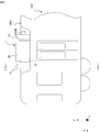
- FIG. 6 is a cross-sectional view taken along the line BB of the power conversion device according to the second embodiment.
- FIG. 8 is a cross-sectional view taken along the line CC of FIG. 8 of the wind guide member according to the third embodiment.
- FIG. 11 is a cross-sectional view taken along the line DD of FIG. 11 of a second modification of the power conversion device according to the embodiment.
- the power conversion device according to the first embodiment will be described by taking as an example a self-cooling power conversion device mounted on the roof of a railroad vehicle and cooling electronic components by using running wind.
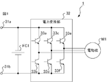
- the power conversion device 1 shown in FIG. 1 converts DC power supplied from a power source (not shown) into three-phase AC power for supplying to the motor M1 which is a load, and supplies the three-phase AC power to the motor M1.
- the power supply is, for example, a current collector that acquires electric power from an overhead wire.
- the electric motor M1 is, for example, a three-phase induction motor.
- the power conversion device 1 is composed of a primary terminal 31a connected to a power supply, a grounded primary terminal 31b, a filter capacitor FC1 having both ends connected to the primary terminals 31a and 31b to remove ripples, and a power supply. It includes a power conversion unit 32 that converts the supplied DC power into three-phase AC power and supplies it to the electric motor M1.
- the power conversion unit 32 includes switching elements 33a and 33b corresponding to the U phase, switching elements 33c and 33d corresponding to the V phase, and switching elements 33e and 33f corresponding to the W phase.
- a switching control unit (not shown) switches the switching elements 33a-33f on and off, so that the power conversion unit 32 converts the DC power supplied from the power source into three-phase AC power and supplies it to the motor M1.
- the power conversion device 1 is provided on the roof 100a of the vehicle 100 as shown in FIG. Specifically, the power conversion device 1 is attached to the upper end of the roof 100a in the vertical direction with the vehicle 100 positioned horizontally.
- the X-axis indicates the traveling direction of the vehicle 100. In other words, the vehicle 100 travels in the positive X-axis direction or the negative X-axis direction.
- the Y-axis indicates the width direction of the vehicle 100, in other words, the sleeper direction.
- the Z-axis is orthogonal to each of the X-axis and the Y-axis. In the state where the vehicle 100 is positioned horizontally, the Z axis indicates the vertical direction.
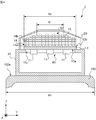
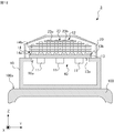
- the power conversion device 1 includes a housing 10 attached to the roof 100a of the vehicle 100 and accommodating an electronic component 11 described later, a cooling device 12 attached to the housing 10, a cooling device 12 described later, and a cover 20 covering the cooling device 12.
- the electronic component 11 indicates an arbitrary heating element such as a switching element 33a-33f, a diode, or a thyristor included in the power conversion unit 32 of FIG.
- the housing 10 accommodates the electronic component 11 and has an opening 10a at the upper part in the vertical direction.
- the opening 10a is closed by the heat receiving block 13 of the cooling device 12 described later. By closing the opening 10a with the heat receiving block 13, it is possible to prevent air, moisture, dust, and the like from flowing into the housing 10.
- the housing 10 has an opening 10a penetrating the housing 10 in the Z-axis direction in a state where the vehicle 100 is positioned horizontally.
- the housing 10 is detachably attached to the roof 100a in the vertical direction while the vehicle 100 is positioned horizontally. If the housing 10 is removable in the vertical direction, it is not necessary to remove the electronic devices located around the power conversion device 1 when the housing 10 is removed from the roof 100a for maintenance work of the power conversion device 1. , Easy to remove. Similarly, when the housing 10 is attached to the roof 100a, it is not necessary to remove the electronic devices located around the power conversion device 1, and the installation work of the housing 10 becomes easy.
- the electronic component 11 is attached to the first main surface 13a of the heat receiving block 13 included in the cooling device 12. Although the details will be described later, the electronic component 11 generates heat when energized and transfers the heat to the heat receiving block 13.
- the cooling device 12 includes a heat receiving block 13 to which the electronic component 11 is attached, and at least one heat pipe 14 which is partially attached to the heat receiving block 13 and extends in a direction away from the heat receiving block 13. A refrigerant is sealed inside each heat pipe 14.
- the cooling device 12 further preferably includes at least one fin 15 attached to the outer surface of the heat pipe 14.
- the cooling device 12 includes a heat receiving block 13, at least one heat pipe 14, and at least one fin 15.
- the unit 40 including the cooling device 12 and the electronic component 11 attached to the heat receiving block 13 of the cooling device 12 is detachable in the vertical direction while the vehicle 100 is positioned horizontally. It is preferably attached to 10.
- the unit 40 includes a heat receiving block 13, at least one heat pipe 14, at least one fin 15, and an electronic component 11 attached to the heat receiving block 13. If the unit 40 can be attached and detached in the vertical direction, it is not necessary to remove the electronic devices located around the power conversion device 1 when removing the unit 40 from the housing 10 for maintenance work of the unit 40. Becomes easier. Similarly, when the unit 40 is attached to the housing 10, it is not necessary to remove the electronic devices located around the power conversion device 1, and the attachment work of the unit 40 becomes easy.
- the upper end of the cooling device 12 in the vertical direction is higher than the upper end of the electronic device located around the power conversion device 1 in a state where the vehicle 100 is located horizontally.
- the heat receiving block 13 has a first main surface 13a and a second main surface 13b that face each other in the extending direction of the Z axis.
- the electronic component 11 is attached to the first main surface 13a.
- a heat pipe 14 is attached to the second main surface 13b. Specifically, the heat pipe 14 is inserted and fixed in the groove formed in the second main surface 13b. Further, the heat receiving block 13 is attached to the housing 10 to close the opening 10a.
- the heat receiving block 13 is made of a material having high thermal conductivity, for example, a metal such as copper or aluminum.
- the heat pipe 14 is inserted into a groove formed in the second main surface 13b of the heat receiving block 13 and attached to the heat receiving block 13. Then, the heat pipe 14 transfers the heat transferred from the electronic component 11 via the heat receiving block 13 to the traveling wind A1 described later generated by the traveling of the vehicle 100.
- the thermal conductivity of the heat pipe 14 is, for example, 5000 W / m ⁇ K, which is a sufficiently large value. Therefore, the heat pipe 14 can efficiently transfer the heat to the surrounding air by quickly transferring the heat transferred from one end fixed to the heat receiving block 13 toward the other end.
- Each heat pipe 14 has a mother pipe 14a and a plurality of branch pipes 14b communicating with the mother pipe 14a. Specifically, each heat pipe 14 has a mother pipe 14a and four branch pipes 14b.
- the mother tube 14a is inserted into a groove formed in the second main surface 13b of the heat receiving block 13, and is fixed to the heat receiving block 13 by an arbitrary fixing method such as adhesion with an adhesive or soldering.
- the mother tube 14a is fixed to the heat receiving block 13 in a partially exposed state.
- the mother tube 14a is made of a material having high thermal conductivity, for example, a metal such as copper or aluminum.
- the branch pipe 14b is fixed to the mother pipe 14a by welding, soldering, etc., and communicates with the mother pipe 14a. Further, the branch pipe 14b extends in a direction away from the heat receiving block 13, specifically, in a direction away from the second main surface 13b. In the first embodiment, the branch pipe 14b extends in the extension direction of the Z axis.
- the branch pipe 14b is made of a material having high thermal conductivity, for example, a metal such as copper or aluminum.
- each heat pipe 14 is filled with a refrigerant.
- the refrigerant exists in a gas-liquid two-phase state.
- the refrigerant is a substance that is vaporized by the heat transmitted from the electronic component 11 and liquefied by radiating heat to the air around the cooling device 12 via the heat pipe 14 and the fin 15 described later, for example, water.
- Each fin 15 is attached to the outer surface of the heat pipe 14. Specifically, the fin 15 has a through hole and is fixed to the branch pipe 14b in a state where the branch pipe 14b is passed through the through hole.
- the fin 15 is made of a material having high thermal conductivity, for example, a metal such as copper or aluminum.
- each fin 15 is formed of a flat plate member, arranged at intervals in the extending direction of the Z axis, and fixed to the branch pipe 14b.
- the cover 20 is attached to the housing 10 and covers the cooling device 12.
- the cover 20 has an arbitrary shape and an arbitrary number of ventilation ports 20a on two surfaces intersecting in the traveling direction of the vehicle 100. Specifically, the cover 20 has ventilation ports 20a penetrating the cover 20 in the X-axis direction on two surfaces orthogonal to the X-axis.
- a mechanism for cooling the electronic component 11 in the power conversion device 1 having the above configuration will be described.
- the electric power conversion unit 32 When the electric power conversion unit 32 is energized and the electronic component 11 generates heat while the vehicle 100 is traveling, heat is transferred from the electronic component 11 to the refrigerant via the heat receiving block 13 and the mother pipe 14a. As a result, the temperature of the refrigerant rises and a part of the refrigerant vaporizes.
- the vaporized refrigerant flows from the mother pipe 14a into the inside of the branch pipe 14b through one end of the branch pipe 14b, and further moves inside the branch pipe 14b toward the other end of the branch pipe 14b. In other words, the vaporized refrigerant moves in the Z-axis positive direction inside the heat pipe 14.
- the traveling wind A1 generated by the traveling of the vehicle 100 flows into the inside of the cover 20 from one ventilation port 20a of the cover 20.
- the traveling wind A1 is a ventilation port formed on one surface of the cover 20. It flows into the inside of the cover 20 from 20a.
- the traveling wind A1 flowing into the inside of the cover 20 flows in the negative direction of the X-axis while contacting the cooling device 12, specifically, the branch pipe 14b and the fin 15. Then, the traveling wind A1 flows out of the cover 20 from the ventilation port 20a formed on the other surface of the cover 20.
- the refrigerant moves inside the branch pipe 14b toward the other end of the branch pipe 14b, heat is transferred from the refrigerant to the traveling wind A1 via the branch pipe 14b and the fins 15. As the refrigerant dissipates heat, the temperature of the refrigerant drops. As a result, the refrigerant liquefies. The liquefied refrigerant flows toward one end of the branch pipe 14b and returns to the mother pipe 14a. In other words, the liquefied refrigerant flows inside the branch pipe 14b in the negative direction of the Z axis and returns to the mother pipe 14a.
- the refrigerant that has been liquefied and returned to the mother pipe 14a transfers heat from the electronic component 11 via the heat receiving block 13, it vaporizes again, flows into the branch pipe 14b, and moves toward the other end of the branch pipe 14b, in other words. Then, it moves in the positive direction of the Z axis.
- the refrigerant repeatedly vaporizes and liquefies as described above and circulates, the heat generated in the electronic component 11 is dissipated to the traveling wind A1 and the electronic component 11 is cooled.
- the electronic component 11 when the electronic component 11 generates heat and heat is transferred from the electronic component 11 to the refrigerant through the heat receiving block 13 and the mother pipe 14a, a temperature difference occurs in the unvaporized refrigerant, that is, the refrigerant in the liquid state. , Convection occurs. Due to convection, the heat transferred from the electronic component 11 is diffused and transferred in the X-axis direction, so that the electronic component 11 is efficiently cooled. The electronic component 11 is cooled by the circulation and convection of the refrigerant described above.
- the branch pipe 14b is extended as long as possible within the range of the vehicle gauge.
- the vehicle gauge indicates a cross section orthogonal to the traveling direction of the vehicle 100, that is, the maximum dimension of the vehicle 100 in the YZ plane. In other words, the vehicle 100 and the equipment mounted on the vehicle 100 are located within the vehicle gauge in the YZ plane.
- the vehicle gauge in the Z-axis direction may differ depending on the position in the Y-axis direction.
- the vehicle gauge in the Z-axis direction corresponds to the maximum dimension of the vehicle 100 in the Z-axis direction on the YZ plane.
- the maximum height of the vehicle 100 at the center in the Y-axis direction is larger than the maximum height of the vehicle 100 at the end in the Y-axis direction.
- the vertical upper end of the branch pipe 14b located at the center in the Y-axis direction is located higher than the vertical upper end of the branch pipe 14b located at the end in the Y-axis direction. Just do it.
- the branch pipe 14b can be extended as long as possible within the range of the vehicle gauge, and the cooling efficiency of the power conversion device 1 is improved.
- the fin 15 is expanded as much as possible within the range of the vehicle gauge.
- the vehicle gauge in the Y-axis direction may vary depending on the position in the Z-axis direction.
- the vehicle gauge in the Y-axis direction corresponds to the maximum dimension of the vehicle 100 in the Y-axis direction on the YZ plane.
- the width of the vehicle gauge in the Y-axis direction becomes narrower as the position in the Z-axis direction becomes higher.
- the length W1 of the fin 15 located in the upper part in the vertical direction in the Y-axis direction may be shorter than the length W2 in the Y-axis direction of the fin 15 located in the lower part in the vertical direction.
- the fins 15 can be expanded as much as possible within the range of the vehicle gauge, and the cooling efficiency of the power conversion device 1 is improved.
- the cover 20 has a shape in line with the vehicle gauge in order to extend the branch pipe 14b as long as possible or to expand the fins 15 as much as possible within the range of the vehicle gauge.
- the downstream temperature is higher than the upstream temperature.
- the cooling efficiency of the heat pipe 14 located in the rear of the vehicle 100 in the traveling direction is lower than the cooling efficiency of the heat pipe 14 located in the front of the vehicle 100 in the traveling direction. Therefore, a temperature difference may occur in the electronic component 11 depending on the position where the heat receiving block 13 is attached. Therefore, it is preferable that the mother pipe 14a extends in the direction in which the traveling wind A1 flows, that is, in the X-axis direction.
- the heat transferred from the electronic component 11 is diffused and transmitted in the X-axis direction by convection of the refrigerant in the liquid state, so that the electronic component 11 The occurrence of temperature difference is suppressed.
- each fin 15 extends along the direction in which the traveling wind A1 flows, that is, the X-axis direction.
- the traveling wind A1 flowing in from the ventilation port 20a smoothly flows along the fins 15, so that the cooling efficiency of the power conversion device 1 is improved.
- the main surface of each fin 15 extends along the X-axis direction, and each fin 15 is positioned horizontally while the vehicle 100 is positioned horizontally.
- the ratio of the length of at least one of the fins 15 in the Y-axis direction to the vehicle body width W3 of the vehicle 100 described later is preferably equal to or more than the threshold value.
- the threshold value may be determined according to the cooling performance required for the cooling device 12, and is, for example, 0.5.
- the length W2 of the lower fin 15 in the vertical direction in the Y-axis direction accounts for 0.5 or more of the vehicle body width W3 of the vehicle 100.
- the size of the fins 15 can be adjusted to the side surface of the conventional power conversion device mounted under the floor of the railway vehicle. It can be made larger than the fins of the provided cooling device. By enlarging the fin 15, heat can be transferred to the traveling wind A1 more efficiently. As a result, the cooling efficiency of the power conversion device 1 becomes higher than the cooling efficiency of the conventional power conversion device.
- the Y-axis of the fin 15 is used. If the length in the direction is increased, the length of the fin 15 in the X-axis direction can be shortened. If the length of the fins 15 in the X-axis direction, that is, in the direction in which the traveling wind A1 flows is shortened, the pressure loss becomes small, and more traveling wind A1 can be passed between the fins 15. As a result, it is possible to improve the cooling efficiency of the power conversion device 1 by using the fins 15 having the same area of the main surface as the conventional fins.
- the power conversion device 1 is installed on the roof 100a of the vehicle 100 and extends in a direction away from the heat receiving block 13 that closes the opening 10a formed in the upper portion of the housing 10 in the vertical direction.
- the heat pipe 14 and the fins 15 attached to the heat pipe 14 are provided.
- the number of motor vehicles equipped with electric motors is small, in other words, in the case of centralized formation, electric motors with high output are adopted, so power is supplied to the electric motors.
- the output of the power converter is also increased, and the amount of heat generated is increased.
- a blower was used to forcibly supply wind to cool the power converter.
- the electronic component 11 of the power conversion device 1 is cooled by using the traveling wind A1 without using a fan, a blower, or the like. Is possible.
- the power conversion device 1 may be provided at a location other than the upper end of the roof 100a of the vehicle 100 in the vertical direction.
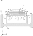
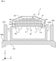
- the power conversion device 1 provided in the accommodating portion 100b provided on the roof 100a of the vehicle 100 will be described in the second embodiment.
- the accommodating portion 100b formed integrally with the roof 100a will be taken as an example, and the accommodating portion 100b accommodating the power conversion device 1 and the power conversion device 1 will be described.
- the roof 100a of the vehicle 100 is formed with a housing portion 100b, which is a recess in which the upper portion in the vertical direction is open.
- the accommodating portion 100b has an open upper surface in the vertical direction in a state where the vehicle 100 is positioned horizontally.
- the accommodating portion 100b accommodates the housing 10 of the power conversion device 1.
- the bottom surface of the housing 10 is attached to the bottom surface of the accommodating portion 100b.
- the mechanism for cooling the components of the power conversion device 1 and the electronic component 11 is the same as that of the first embodiment.
- At least one of the upper ends of the heat pipe 14 in the vertical direction is located higher than the upper end of the roof 100a in the vertical direction when the vehicle 100 is located horizontally.
- the upper end of each heat pipe 14 in the vertical direction is located higher than the upper end of the roof 100a in the vertical direction. Therefore, even if the power conversion device 1 is provided in the accommodating portion 100b, the traveling wind A1 can come into contact with each heat pipe 14, and the electronic component 11 can be cooled.
- At least one of the fins 15 is located higher than the upper end of the roof 100a in the vertical direction in a state where the vehicle 100 is positioned horizontally. As shown in FIGS. 6 and 7, in the second embodiment, each fin 15 is located higher than the upper end of the roof 100a in the vertical direction. Therefore, even if the power conversion device 1 is provided in the accommodating portion 100b, the traveling wind A1 can come into contact with each fin 15, and the electronic component 11 can be cooled.
- the power conversion device 1 can cool the electronic component 11 even if it is installed in the accommodating portion 100b formed on the roof 100a of the vehicle 100.
- the power conversion device 1 can be arranged on the roof 100a and the electronic component 11 can be cooled. Become.
- the power conversion device 1 includes a wind guide member 21 provided at a position adjacent to the outer surface of the housing 10 intersecting the traveling direction of the vehicle 100, that is, the X-axis direction.
- the wind guide member 21 guides the traveling wind A1 to the cooling device 12.
- the air guide member 21 guides the traveling wind A1 to the heat pipe 14 and the fins 15 through the ventilation port 20a formed in the cover 20.
- the two wind guide members 21 are arranged side by side in the X-axis direction with the housing 10 interposed therebetween.
- the wind guide member 21 has the shape of a cylinder whose penetrating direction is along the X-axis direction and whose side surfaces are notched.
- 9 is a cross-sectional view taken along the line CC of FIG. Specifically, the wind guide member 21 has the shape of a square cylinder with a notched side surface.
- the wind guide member 21 is attached to the roof 100a so that the notched portion of the cylinder faces the roof 100a.
- the wind guide member 21 is attached to the bottom surface of the accommodating portion 100b in which the cut portion of the cylinder is formed on the roof 100a.
- the air guide member 21 is attached to the roof 100a to form a ventilation path 21a that guides the traveling wind A1 to the cooling device 12 with the roof 100a.
- the ventilation member 21 forms a ventilation passage 21a conducting in the X-axis direction in order to guide the traveling wind A1 to the heat pipe 14 and the fins 15 through the ventilation port 20a formed in the cover 20.
- the area of the end face of the ventilation passage 21a formed by the ventilation member 21 near the housing 10 is smaller than the area of the end face of the ventilation passage 21a far from the housing 10. In this case, the traveling wind A1 flowing along the roof 100a can be efficiently guided to the heat pipe 14 and the fins 15.
- the traveling wind A1 can be efficiently guided to the cooling device 12.
- the power conversion device 1 may include two wind guide members 21 provided side by side in the X-axis direction with the housing 10 sandwiched therein.
- the wind guide member 21 may be provided at the upper end of the roof 100a in the vertical direction while the vehicle 100 is located horizontally.
- the power supplied to the power converter 1 is not limited to DC power.
- the power conversion device 1 may be a converter that converts AC power into DC power.
- the power supplied by the power converter 1 to the load is not limited to the three-phase AC power.
- the power converter 1 may supply DC power to a load that is a DC motor.
- the motor M1 is not limited to the three-phase induction motor, but may be a synchronous motor, a DC motor, or the like. Further, the power conversion device 1 is not limited to the self-cooling type power conversion device that supplies power to the electric motor M1. As an example, the load supplied by the power conversion device 1 is an arbitrary electronic device that consumes electric power, such as a lighting device and an air conditioning device.
- the power conversion device 1 is not limited to a railroad vehicle, and can be mounted on an arbitrary moving body such as a trolleybus or a tram in which a running wind A1 is generated.
- the shape of the housing 10 is arbitrary as long as it accommodates the electronic component 11 inside and can be attached to the roof 100a.
- the vertical upper surface of the housing 10 may be tilted with respect to the horizontal plane with the vehicle 100 positioned horizontally.
- the housing 10 has an upper surface inclined toward the front in the traveling direction of the vehicle. As a result, the running wind A1 can be efficiently brought into contact with the heat pipe 14 and the fins 15.
- the heat receiving block 13 may be formed of a single plate-shaped member or may be formed by combining a plurality of plate-shaped members. By forming the heat receiving block 13 with a single plate-shaped member, the manufacturing process of the power conversion device 1 can be simplified, and the airtightness of the housing 10 can be improved.
- the shape of the heat pipe 14 is arbitrary as long as it is a shape that enables the electronic component 11 to be cooled by the circulation of the refrigerant sealed inside.
- the power conversion device 2 shown in FIG. 10 includes a heat pipe 22 bent in an L shape. A part of the heat pipe 22 extends in the X-axis direction, and the other part extends in the Z-axis direction.
- the power conversion device 2 may be provided in the accommodating portion 100b formed on the roof 100a, as in the second embodiment.
- the shape of the heat pipe 14 may be U-shaped or annular.
- the shape of the cross section orthogonal to the stretching direction of the heat pipe 14 is not limited to a circular shape, and may be a flat shape.
- the shape of the cross section of the mother pipe 14a and the branch pipe 14b orthogonal to the extending direction may be circular or flat.
- the flat shape is a shape obtained by deforming a part of the width of the circle to be narrower than the original circle, and includes an ellipse, a streamlined shape, an oval, and the like.
- the oval means a shape in which the outer edges of circles having the same diameter are connected by a straight line.
- the heat pipe 14 may communicate with the groove formed in the heat receiving block 13.
- the heat pipe 14 may have a tubular shape with one end closed.
- the number of heat pipes 14 is not limited to the above example, and is arbitrary.
- the number of mother pipes 14a and the number of branch pipes 14b attached to each mother pipe 14a are not limited to the above examples, and are arbitrary.
- the positions of the upper ends of the heat pipes 14 in the vertical direction may be different as shown in the embodiment, or may be the same as each other.
- the number of fins 15 is not limited to the above example and is arbitrary.
- the length of the width of the fins 15 in the Y-axis direction may be different as shown in the embodiment, or may be the same as each other.
- the shape of the fin 15 is not limited to the above example, and is arbitrary.
- the fin 15 may be formed of a flat plate member or a bent plate-shaped member as shown in the embodiment.
- the fins 15 formed of one plate-shaped member are arranged side by side in the Z-axis direction.
- the shape of the fins 15 is not limited to the above example, and each fin 15 may be formed of a plurality of plate-shaped members.
- the cooling device 12 included in the power conversion device 3 shown in FIG. 12, which is a cross-sectional view taken along the line DD of FIGS. 11 and 11, has a plurality of fins 23.
- Each fin 23 is formed of flat plate members 23a and 23b.
- Each fin 15 may be formed of the same member as each other, or at least one of the fins 15 may be formed of a member different from the other fins 15.
- the thermal conductivity of at least one of the fins 15 is different from the thermal conductivity of the other fins 15.
- the thermal conductivity of the fins 15 located in the upper part in the vertical direction is preferably higher than the thermal conductivity of the fins 15 located in the lower part in the vertical direction.
- the upper fin 15 in the vertical direction may be formed of copper
- the lower fin 15 in the vertical direction may be formed of aluminum.
- the fin 15 located at the upper part in the vertical direction can easily come into contact with the traveling wind A1 even if other equipment is provided around the power conversion device 1. Therefore, by increasing the thermal conductivity of the fins 15 located at the upper part in the vertical direction, it is possible to improve the cooling efficiency of the power conversion device 1.
- the shape of the cover 20 is arbitrary as long as it covers the cooling device 12 and allows the running wind A1 to flow into the inside.
- the cover 20 may have a curved upper surface in the vertical direction.
- the cover 20 may have a flat upper surface in the vertical direction.
- the cover 20 preferably has a shape that maximizes the internal space within the range of the vehicle gauge.
- the shape of the air guide member 21 is not limited to the square cylinder whose side surface is cut out, and is arbitrary as long as it can guide the traveling wind A1 to the cooling device 12.
- the air guide member 21 may have a cylindrical shape with a notched side surface.
- the wind guide member 21 may have the shape of a cylinder having a part of the side surface attached to the roof 100a and having a polygonal cross section.
- the wind guide member 21 may be provided separately from each of the housing 10 and the cover 20, or may be provided in contact with at least one of the housing 10 and the cover 20. You may.
- the number of wind guide members 21 is arbitrary.
- one wind guide member 21 may be provided in front of the traveling direction of the vehicle.
- the switching elements 33a-33f may be formed of a wide bandgap semiconductor.
- Wide bandgap semiconductors include, for example, silicon carbide, gallium nitride based materials, or diamond.
- the opening surface of the accommodating portion 100b may be positioned horizontally or may be inclined with respect to the horizontal plane in a state where the vehicle 100 is positioned horizontally.
- the accommodating portion 100b may be formed separately from the roof 100a.
- the accommodating portion 100b may be a pair of roof coverings 100c facing each other in the width direction.
- the main surfaces of the pair of roof covers 100c face each other in the width direction.
- each of the pair of roof covers 100c may be a plate-shaped member having a flat main surface or a plate-shaped member having a curved main surface.
- the power conversion device 1-3 may further include a sealing member that surrounds the opening 10a and abuts on each of the housing 10 and the heat receiving block 13. By providing the sealing member, the airtightness of the housing 10 is enhanced.
- 1,2,3 power converter 10 housing, 10a opening, 11 electronic parts, 12 cooling device, 13 heat receiving block, 13a first main surface, 13b second main surface, 14,22 heat pipe, 14a mother tube , 14b branch pipe, 15, 23 fins, 20 cover, 20a ventilation port, 21 ventilation member, 21a ventilation path, 23a, 23b flat plate member, 31a, 31b primary terminal, 32 power converter, 33a, 33b, 33c, 33d, 33e, 33f switching element, 40 units, 100 vehicles, 100a roof, 100b housing, 100c roof cover, A1 running wind, FC1 filter capacitor, M1 electric power, W1, W2 length, W3 body width.
Landscapes
- Engineering & Computer Science (AREA)
- Microelectronics & Electronic Packaging (AREA)
- Physics & Mathematics (AREA)
- Thermal Sciences (AREA)
- Power Engineering (AREA)
- Cooling Or The Like Of Electrical Apparatus (AREA)
- Inverter Devices (AREA)
- Electric Propulsion And Braking For Vehicles (AREA)
Priority Applications (5)
| Application Number | Priority Date | Filing Date | Title |
|---|---|---|---|
| JP2022512973A JP7134376B2 (ja) | 2020-03-31 | 2020-03-31 | 電力変換装置 |
| US17/800,036 US12250796B2 (en) | 2020-03-31 | 2020-03-31 | Power conversion device |
| EP20929607.8A EP4131767B1 (en) | 2020-03-31 | 2020-03-31 | Power conversion device |
| PCT/JP2020/014762 WO2021199252A1 (ja) | 2020-03-31 | 2020-03-31 | 電力変換装置 |
| CN202090001127.4U CN218788733U (zh) | 2020-03-31 | 2020-03-31 | 功率转换装置 |
Applications Claiming Priority (1)
| Application Number | Priority Date | Filing Date | Title |
|---|---|---|---|
| PCT/JP2020/014762 WO2021199252A1 (ja) | 2020-03-31 | 2020-03-31 | 電力変換装置 |
Publications (1)
| Publication Number | Publication Date |
|---|---|
| WO2021199252A1 true WO2021199252A1 (ja) | 2021-10-07 |
Family
ID=77928225
Family Applications (1)
| Application Number | Title | Priority Date | Filing Date |
|---|---|---|---|
| PCT/JP2020/014762 Ceased WO2021199252A1 (ja) | 2020-03-31 | 2020-03-31 | 電力変換装置 |
Country Status (5)
| Country | Link |
|---|---|
| US (1) | US12250796B2 (https=) |
| EP (1) | EP4131767B1 (https=) |
| JP (1) | JP7134376B2 (https=) |
| CN (1) | CN218788733U (https=) |
| WO (1) | WO2021199252A1 (https=) |
Cited By (5)
| Publication number | Priority date | Publication date | Assignee | Title |
|---|---|---|---|---|
| JPWO2023199445A1 (https=) * | 2022-04-13 | 2023-10-19 | ||
| EP4424539A4 (en) * | 2021-10-29 | 2024-12-11 | Mitsubishi Electric Corporation | ELECTRONIC DEVICE |
| US20250040103A1 (en) * | 2022-01-26 | 2025-01-30 | Mitsubishi Electric Corporation | Electronic device |
| JP7750454B1 (ja) * | 2024-09-19 | 2025-10-07 | 三菱電機株式会社 | 駆動装置 |
| WO2026062917A1 (ja) * | 2024-09-19 | 2026-03-26 | 三菱電機株式会社 | 駆動装置 |
Citations (5)
| Publication number | Priority date | Publication date | Assignee | Title |
|---|---|---|---|---|
| JPH07142655A (ja) * | 1993-11-12 | 1995-06-02 | Fuji Electric Co Ltd | ヒートパイプ冷却体 |
| JP2003079164A (ja) * | 2001-08-31 | 2003-03-14 | Toshiba Transport Eng Inc | 電力変換装置 |
| JP2011050166A (ja) | 2009-08-27 | 2011-03-10 | Hitachi Ltd | 電力変換装置 |
| JP2011259536A (ja) * | 2010-06-07 | 2011-12-22 | Hitachi Ltd | 冷却装置,電力変換装置,鉄道車両 |
| JP2017039481A (ja) * | 2015-08-21 | 2017-02-23 | 株式会社東芝 | 電力変換装置及び鉄道車両 |
Family Cites Families (3)
| Publication number | Priority date | Publication date | Assignee | Title |
|---|---|---|---|---|
| JP4098534B2 (ja) * | 2002-02-28 | 2008-06-11 | 三菱電機株式会社 | 移動体用冷却装置 |
| US20100000804A1 (en) * | 2008-07-02 | 2010-01-07 | Ming-Hsiang Yeh | Solar vehicle |
| JP6888468B2 (ja) * | 2017-08-01 | 2021-06-16 | 富士電機株式会社 | 鉄道車両用電力変換装置 |
-
2020
- 2020-03-31 EP EP20929607.8A patent/EP4131767B1/en active Active
- 2020-03-31 JP JP2022512973A patent/JP7134376B2/ja active Active
- 2020-03-31 WO PCT/JP2020/014762 patent/WO2021199252A1/ja not_active Ceased
- 2020-03-31 CN CN202090001127.4U patent/CN218788733U/zh active Active
- 2020-03-31 US US17/800,036 patent/US12250796B2/en active Active
Patent Citations (5)
| Publication number | Priority date | Publication date | Assignee | Title |
|---|---|---|---|---|
| JPH07142655A (ja) * | 1993-11-12 | 1995-06-02 | Fuji Electric Co Ltd | ヒートパイプ冷却体 |
| JP2003079164A (ja) * | 2001-08-31 | 2003-03-14 | Toshiba Transport Eng Inc | 電力変換装置 |
| JP2011050166A (ja) | 2009-08-27 | 2011-03-10 | Hitachi Ltd | 電力変換装置 |
| JP2011259536A (ja) * | 2010-06-07 | 2011-12-22 | Hitachi Ltd | 冷却装置,電力変換装置,鉄道車両 |
| JP2017039481A (ja) * | 2015-08-21 | 2017-02-23 | 株式会社東芝 | 電力変換装置及び鉄道車両 |
Non-Patent Citations (1)
| Title |
|---|
| See also references of EP4131767A4 |
Cited By (8)
| Publication number | Priority date | Publication date | Assignee | Title |
|---|---|---|---|---|
| EP4424539A4 (en) * | 2021-10-29 | 2024-12-11 | Mitsubishi Electric Corporation | ELECTRONIC DEVICE |
| US20250040103A1 (en) * | 2022-01-26 | 2025-01-30 | Mitsubishi Electric Corporation | Electronic device |
| JPWO2023199445A1 (https=) * | 2022-04-13 | 2023-10-19 | ||
| WO2023199445A1 (ja) * | 2022-04-13 | 2023-10-19 | 三菱電機株式会社 | 電子機器 |
| JP7665100B2 (ja) | 2022-04-13 | 2025-04-18 | 三菱電機株式会社 | 電子機器 |
| EP4509380A4 (en) * | 2022-04-13 | 2025-06-04 | Mitsubishi Electric Corporation | ELECTRONIC DEVICE |
| JP7750454B1 (ja) * | 2024-09-19 | 2025-10-07 | 三菱電機株式会社 | 駆動装置 |
| WO2026062917A1 (ja) * | 2024-09-19 | 2026-03-26 | 三菱電機株式会社 | 駆動装置 |
Also Published As
| Publication number | Publication date |
|---|---|
| US20230073236A1 (en) | 2023-03-09 |
| CN218788733U (zh) | 2023-04-04 |
| EP4131767B1 (en) | 2026-02-25 |
| EP4131767A4 (en) | 2023-05-31 |
| EP4131767A1 (en) | 2023-02-08 |
| JPWO2021199252A1 (https=) | 2021-10-07 |
| JP7134376B2 (ja) | 2022-09-09 |
| US12250796B2 (en) | 2025-03-11 |
Similar Documents
| Publication | Publication Date | Title |
|---|---|---|
| JP7134376B2 (ja) | 電力変換装置 | |
| JP2000092819A (ja) | 半導体冷却装置 | |
| EP2825011A2 (en) | Traction converter and railway vehicle | |
| EP3546272A1 (en) | Power conversion device for railway vehicle | |
| JP2011259536A (ja) | 冷却装置,電力変換装置,鉄道車両 | |
| US20190148259A1 (en) | Power converter and power converter for railroad vehicle | |
| CN112153854A (zh) | 功率模块用冷板及电机控制器 | |
| JP7408017B2 (ja) | 電子機器 | |
| JP7050996B2 (ja) | 冷却装置および電力変換装置 | |
| GB2523625A (en) | Power conversion device and railway vehicle equipped with the same | |
| CN221930483U (zh) | 电子设备 | |
| JP6837565B2 (ja) | 鉄道車両の電力変換装置および電力変換装置を搭載した鉄道車両 | |
| JP2007043064A (ja) | パワーモジュールの冷却装置 | |
| JP2020171196A (ja) | 鉄道車両の電力変換装置 | |
| JP7520259B2 (ja) | 電子機器 | |
| JP3244143U (ja) | 電力変換装置 | |
| JP7199574B2 (ja) | 冷却装置および電力変換装置 | |
| JP7446528B2 (ja) | 車載機器 | |
| JP2018037557A (ja) | 電力変換装置および電力変換装置を搭載した鉄道車両 | |
| JP4549086B2 (ja) | 鉄道車両用走行風冷却装置 | |
| JP7408031B2 (ja) | 電子機器 | |
| JP2791270B2 (ja) | 半導体冷却器 | |
| JP7665100B2 (ja) | 電子機器 | |
| JP5494637B2 (ja) | パワーモジュールの冷却装置 | |
| JP7154296B2 (ja) | 車両用電力変換装置 |
Legal Events
| Date | Code | Title | Description |
|---|---|---|---|
| 121 | Ep: the epo has been informed by wipo that ep was designated in this application |
Ref document number: 20929607 Country of ref document: EP Kind code of ref document: A1 |
|
| ENP | Entry into the national phase |
Ref document number: 2022512973 Country of ref document: JP Kind code of ref document: A |
|
| NENP | Non-entry into the national phase |
Ref country code: DE |
|
| ENP | Entry into the national phase |
Ref document number: 2020929607 Country of ref document: EP Effective date: 20221031 |
|
| WWG | Wipo information: grant in national office |
Ref document number: 17800036 Country of ref document: US |
|
| WWG | Wipo information: grant in national office |
Ref document number: 2020929607 Country of ref document: EP |