WO2021193416A1 - 光学積層体および物品 - Google Patents
光学積層体および物品 Download PDFInfo
- Publication number
- WO2021193416A1 WO2021193416A1 PCT/JP2021/011337 JP2021011337W WO2021193416A1 WO 2021193416 A1 WO2021193416 A1 WO 2021193416A1 JP 2021011337 W JP2021011337 W JP 2021011337W WO 2021193416 A1 WO2021193416 A1 WO 2021193416A1
- Authority
- WO
- WIPO (PCT)
- Prior art keywords
- value
- optical laminate
- incident
- light
- layer
- Prior art date
- Legal status (The legal status is an assumption and is not a legal conclusion. Google has not performed a legal analysis and makes no representation as to the accuracy of the status listed.)
- Ceased
Links
Images


Classifications
-
- G—PHYSICS
- G02—OPTICS
- G02B—OPTICAL ELEMENTS, SYSTEMS OR APPARATUS
- G02B1/00—Optical elements characterised by the material of which they are made; Optical coatings for optical elements
- G02B1/10—Optical coatings produced by application to, or surface treatment of, optical elements
- G02B1/11—Anti-reflection coatings
-
- B—PERFORMING OPERATIONS; TRANSPORTING
- B32—LAYERED PRODUCTS
- B32B—LAYERED PRODUCTS, i.e. PRODUCTS BUILT-UP OF STRATA OF FLAT OR NON-FLAT, e.g. CELLULAR OR HONEYCOMB, FORM
- B32B7/00—Layered products characterised by the relation between layers; Layered products characterised by the relative orientation of features between layers, or by the relative values of a measurable parameter between layers, i.e. products comprising layers having different physical, chemical or physicochemical properties; Layered products characterised by the interconnection of layers
- B32B7/02—Physical, chemical or physicochemical properties
- B32B7/023—Optical properties
-
- G—PHYSICS
- G02—OPTICS
- G02B—OPTICAL ELEMENTS, SYSTEMS OR APPARATUS
- G02B1/00—Optical elements characterised by the material of which they are made; Optical coatings for optical elements
- G02B1/10—Optical coatings produced by application to, or surface treatment of, optical elements
- G02B1/11—Anti-reflection coatings
- G02B1/113—Anti-reflection coatings using inorganic layer materials only
- G02B1/115—Multilayers
-
- G—PHYSICS
- G02—OPTICS
- G02B—OPTICAL ELEMENTS, SYSTEMS OR APPARATUS
- G02B1/00—Optical elements characterised by the material of which they are made; Optical coatings for optical elements
- G02B1/10—Optical coatings produced by application to, or surface treatment of, optical elements
- G02B1/14—Protective coatings, e.g. hard coatings
-
- G—PHYSICS
- G02—OPTICS
- G02F—OPTICAL DEVICES OR ARRANGEMENTS FOR THE CONTROL OF LIGHT BY MODIFICATION OF THE OPTICAL PROPERTIES OF THE MEDIA OF THE ELEMENTS INVOLVED THEREIN; NON-LINEAR OPTICS; FREQUENCY-CHANGING OF LIGHT; OPTICAL LOGIC ELEMENTS; OPTICAL ANALOGUE/DIGITAL CONVERTERS
- G02F1/00—Devices or arrangements for the control of the intensity, colour, phase, polarisation or direction of light arriving from an independent light source, e.g. switching, gating or modulating; Non-linear optics
- G02F1/01—Devices or arrangements for the control of the intensity, colour, phase, polarisation or direction of light arriving from an independent light source, e.g. switching, gating or modulating; Non-linear optics for the control of the intensity, phase, polarisation or colour
- G02F1/13—Devices or arrangements for the control of the intensity, colour, phase, polarisation or direction of light arriving from an independent light source, e.g. switching, gating or modulating; Non-linear optics for the control of the intensity, phase, polarisation or colour based on liquid crystals, e.g. single liquid crystal display cells
- G02F1/133—Constructional arrangements; Operation of liquid crystal cells; Circuit arrangements
- G02F1/1333—Constructional arrangements; Manufacturing methods
- G02F1/1335—Structural association of cells with optical devices, e.g. polarisers or reflectors
- G02F1/133502—Antiglare, refractive index matching layers
-
- G—PHYSICS
- G09—EDUCATION; CRYPTOGRAPHY; DISPLAY; ADVERTISING; SEALS
- G09F—DISPLAYING; ADVERTISING; SIGNS; LABELS OR NAME-PLATES; SEALS
- G09F9/00—Indicating arrangements for variable information in which the information is built-up on a support by selection or combination of individual elements
-
- G—PHYSICS
- G02—OPTICS
- G02B—OPTICAL ELEMENTS, SYSTEMS OR APPARATUS
- G02B1/00—Optical elements characterised by the material of which they are made; Optical coatings for optical elements
- G02B1/10—Optical coatings produced by application to, or surface treatment of, optical elements
- G02B1/18—Coatings for keeping optical surfaces clean, e.g. hydrophobic or photo-catalytic films
Definitions
- the present invention relates to optical laminates and articles.
- the present application claims priority under Japanese Patent Application No. 2020-051220 filed in Japan on March 23, 2020 and Japanese Patent Application No. 2021-0439315 filed in Japan on March 17, 2021. The contents are used here.
- Image display devices such as flat panel displays (FPDs) are widely used in mobile phones, smartphones, car navigation devices, and the like.
- FPDs flat panel displays
- a conventional image display device it is required to make it difficult to visually recognize color unevenness due to a viewing angle.
- Color unevenness is a phenomenon in which the tint (chromaticity) looks different depending on the viewing angle.
- Patent Document 1 states that when light A having a wavelength of 380 nm to 780 nm by a standard light source D65 is incident at an incident angle of 5 °, the visual sensitivity reflectance is 0.5% or less, and the incident angle of the light A is 0.5% or less.
- An antireflection film is described in which the ratio of the difference between the maximum value and the minimum value of (b * value difference / a * value difference) is 2 or more.
- the optical laminate such as the antireflection film installed on the image display device does not easily color the reflected light reflected by the image display device on which it is installed. Further, as the optical laminate, it is preferable that color unevenness is not visually recognized even if the viewing angle of the image display device on which the optical laminate is installed is changed.
- color unevenness may be visually recognized by changing the viewing angle of the image display device on which the laminated body is installed. Therefore, in the conventional optical laminate installed on the image display device, it is difficult to color the reflected light reflected by the image display device, and color unevenness occurs even if the viewing angle of the image display device is changed. It is required to make it difficult to see.
- the present invention has been made in view of the above circumstances, and is an optical laminate provided in an article, which makes it difficult to color the reflected light reflected by the article, and makes it difficult for color unevenness to be visually recognized even if the viewing angle of the article is changed.
- the purpose is to provide.
- Another object of the present invention is to provide an article in which the optical laminate of the present invention is provided, the reflected light is less likely to be colored, and color unevenness is less likely to be visually recognized even if the viewing angle is changed.
- the present invention proposes the following means.
- the transparent base material, the hard coat layer, and the antireflection layer are laminated in this order.
- the antireflection layer is composed of a laminate in which a low refractive index material layer and a high refractive index material layer made of a material having a higher refractive index than the low refractive index material layer are alternately laminated.
- the a * and b * values of the reflected light in the CIE-Lab color system when light having a wavelength of 380 nm to 780 nm from the standard light source D65 is incidentally satisfy the following (condition A) to (condition C).
- Optical laminate Optical laminate.
- the a * value and b * value of the reflected light in the CIE-Lab color system when light having a wavelength of 380 nm to 780 nm is incident by the standard light source D65 is the above (condition A). Due to the synergistic effect of satisfying (Condition C), it is difficult to color the reflected light reflected by the article, and it is difficult to visually recognize the color unevenness even if the viewing angle of the article is changed. Further, since the article of the present invention includes the optical laminate of the present invention, the reflected light from the article is less likely to be colored, and uneven color is less likely to be visually recognized even if the viewing angle is changed.
- FIG. 1 is a schematic cross-sectional view showing an example of the optical laminate of the present invention.
- FIG. 2 shows the CIE- of the reflected light when light having a wavelength of 380 nm to 780 nm by the standard light source D65 is incident on the optical laminate shown in FIG. 1 using the L * a * b * color space chromaticity diagram. It is a figure for demonstrating a * value and b * value in a Lab color system.
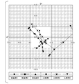
- FIG. 3 shows that light is incident on the surfaces of the optical laminates of Examples 1 to 3 and Comparative Examples 1 to 3 at incident angles of 5 °, 10 °, 20 °, 30 °, 40 °, and 50 °.
- FIG. 4 is an enlarged graph showing the central portion of the graph of FIG.
- FIG. 5 is a photograph of a test piece when light is incident on the surface of each optical laminate at incident angles of 5 °, 10 °, 20 °, 30 °, and 40 °.
- the present inventors have conducted intensive studies as shown below.
- the present inventors have been able to visually recognize an article in order to obtain an optical laminate in which the reflected light reflected by the article provided with the optical laminate is difficult to be colored and color unevenness is hardly visually recognized even if the viewing angle of the article is changed. Focusing on the relationship between the angle and the chromaticity (saturation and hue) of the reflected light, we made extensive studies.
- the present inventors have found that not only the saturation of the reflected light but also the change in the hue of the reflected light by changing the viewing angle has a great influence on the visibility of the color unevenness. Then, the present inventors sufficiently reduce the saturation of the reflected light when light having an incident angle of 30 ° to 40 ° is incident on the surface, and the incident angle is within the range of 5 ° to 30 °. It was found that by reducing the change in hue of the reflected light when light is incident, color unevenness is less likely to be visually recognized even if the viewing angle of the article is changed.
- the present inventors have incidented the saturation of the reflected light when light having an incident angle of 30 ° to 40 ° is incident on the surface, and the light within the range of the incident angle of 5 ° to 30 °.
- the saturation of the reflected light when the light is incident at an incident angle of 5 ° is higher than that when the light is incident at an incident angle of 30 ° to 40 °. It was found that even if it is large, it is difficult to visually recognize the coloring of the reflected light reflected on the article.
- the present inventors consider the reflected light when the light is incident on the surface at an incident angle of 30 ° to 40 ° and when the light is incident at an incident angle of 5 °.
- the chromaticity range and the change in the hue of the reflected light when light in the range of the incident angle of 5 ° to 30 ° was incident on the surface were repeatedly studied.
- the a * value and b * value of the reflected light in the CIE-Lab color system when light having a wavelength of 380 nm to 780 nm by the standard light source D65 is incident satisfies the following (condition A) to (condition C). It has been found that an optical laminate may be used.
- FIG. 1 is a schematic cross-sectional view showing an example of the optical laminate of the present invention.
- a transparent base material 2 a hard coat layer 3, an antireflection layer 4 (laminate), and an antifouling layer 5 are laminated in this order.
- the optical laminate 1 shown in FIG. 1 is provided in an article (not shown). Examples of the article include those provided with the optical laminate 1 on the surface of an image display device (not shown).
- FIG. 2 describes the a * value and the b * value of the reflected light in the CIE-Lab color system when light having a wavelength of 380 nm to 780 nm is incident on the optical laminate shown in FIG. 1 by the standard light source D65.
- the a * value and the b * value indicate the chromaticity, and the larger the absolute value of the a * value and the b * value is, the larger the saturation is. That is, in FIG. 2, the larger the absolute value of the a * value and the b * value is, the more vivid the color is, and the smaller the absolute value of the a * value and the b * value is, the more vivid the color is. , A color close to achromatic.
- the coordinates of + a * are the hues in the red direction
- the coordinates of -a * are the hues in the green direction
- the coordinates of + b * are the hues in the yellow direction
- the coordinates of -b * are the hues in the blue direction.
- the third quadrant (-a * , -b * ) corresponds to red to orange to yellow, yellow to yellowish green to green, green to bluish green to blue, and blue to purple to red.
- the hue of the reflected light changes to another quadrant depending on the incident angle (when a quadrant straddle occurs), the hue changes significantly, so that color unevenness becomes easily visible. It is preferable that the hue quadrant of the reflected light does not change depending on the incident angle, in other words, the hue of the reflected light stays within the same quadrant depending on the incident angle.
- the a * value and b * value of the reflected light in the CIE-Lab color system when light having a wavelength of 380 nm to 780 nm is incident from the standard light source D65 are as described above (condition A). )-(Condition C) is satisfied.
- Each of the above conditions (Condition A) to (Condition C) applies to the transparent base material 2 forming the optical laminate 1, the hard coat layer 3, the antireflection layer 4, and the antifouling layer 5. It can be adjusted by appropriately selecting the material and thickness.
- the a * value and b * value of the reflected light when light is incident on the surface of the optical laminate 1 at an incident angle of 30 ° to 40 ° are absolute values, respectively. 3 or less (in the region indicated by reference numeral A in FIG. 2) (condition A). Therefore, in the optical laminate 1 of the present embodiment, the saturation of the reflected light when light is incident at an incident angle of 30 ° to 40 ° is sufficiently small, and color unevenness due to changing the viewing angle of the article is visually recognized. It is hard to be done.
- the a * value and the b * value described above are preferably 2.5 or less in absolute value, respectively.
- the color unevenness caused by changing the viewing angle of the article becomes the optical laminate 1 that is more difficult to be visually recognized. If either one or both of the above a * and b * values exceeds 3 in absolute value, the saturation of the reflected light when light is incident at an incident angle of 30 ° to 40 ° is high. Therefore, color unevenness due to changing the viewing angle of the article becomes easy to be visually recognized.
- the optical laminate 1 shown in FIG. 1 has a * value and b * value of reflected light when light is incident on the surface of the optical laminate 1 at incident angles of 5 °, 10 °, 20 °, and 30 °.
- condition B ⁇ Maximum value of (
- is a numerical value corresponding to the hue of the reflected light.
- is less than 1.0 emits light at an incident angle of 5 ° to 30 °.
- the hue change of the reflected light is small when it is made to move. That is, the reflected light when the light is incident at an incident angle of 5 ° to 30 ° has similar hues. Therefore, in the optical laminate 1 of the present embodiment, the hue change of the reflected light due to the change in the viewing angle of the article is small, and the color unevenness is hard to be visually recognized.
- the hue change of the reflected light due to the change in the viewing angle of the article is large, so that the color unevenness is easily recognized.
- is preferably 0.5 or less, and more preferably 0.3 or less.
- the optical laminate 1 of the present embodiment satisfies the above (condition A) and (condition B), the saturation of the reflected light when light is incident at an incident angle of 30 ° to 40 ° is sufficiently small (FIG. In No. 2, the hue change of the reflected light when light is incident at an incident angle of 5 ° to 30 ° (within the region indicated by reference numeral A) is sufficiently small (satisfies the equation (B1)).
- the chromaticity (saturation and hue) of the reflected light of the optical laminate 1 changes continuously by changing the viewing angle of the article. Therefore, the optical laminate 1 satisfying the above (condition A) and (condition B) has, for example, the reflected light having a similar hue when light having an incident angle of 5 ° to 30 ° is continuously incident.
- the optical laminate 1 of the present embodiment has a sufficiently small saturation of reflected light when light is incident at an incident angle of 30 ° to 40 ° (condition A), and therefore, when the incident angle is 30 ° to 40 °. Even if the hue of the reflected light is different when the incident angle is 5 ° to 30 °, it is difficult to visually recognize the color unevenness. Therefore, in the optical laminate 1 of the present embodiment, color unevenness due to changing the viewing angle of the article is less likely to be visually recognized.
- one or both of the a * value and the b * value of the reflected light when light is incident on the surface of the optical laminate 1 at an incident angle of 5 ° is an absolute value of 5.
- the a * value and the b * value are in the range of 15 or less in absolute value (condition C).
- reference numeral C indicates a region in which the a * value and the b * value are 5 or more and 15 or less in absolute value.
- the above a * value and b * value are preferably 10 or less in absolute value, respectively. In this case, the colored light reflected on the article becomes the optical laminate 1 which is more difficult to see.
- the saturation of the reflected light when light is incident at an incident angle of 5 ° is an incident angle of 30. Even when light is incident at ° to 40 ° (inside the region indicated by reference numeral A in FIG. 2) and outside (for example, in the region indicated by reference numeral C in FIG. 2), it is reflected by the article. It is difficult to see the coloring of the reflected light. However, if either one or both of the above a * and b * values exceeds 15 in absolute value, the saturation of the reflected light when light is incident at an incident angle of 5 ° is large, and therefore the saturation of the reflected light is large. The coloring of the reflected light reflected on the article becomes easy to see.
- one or both of the a * value and the b * value of the reflected light when light is incident on the surface of the optical laminate 1 at an incident angle of 5 ° is absolute.
- the value is in the range of 5 or more (condition C). Therefore, for example, it is compared with the case where the a * value and the b * value of the reflected light when the light is incident at an incident angle of 5 ° are less than 3 (within the region indicated by the reference numeral A in FIG. 2).
- the material and thickness of each layer forming the optical laminate 1 and the choice of manufacturing method are increased, and the optical laminate 1 can be easily and efficiently manufactured.
- one or both of the above a * value and b * value may be 8 or more in absolute value.
- the material and thickness of each layer forming the optical laminate 1 and the selection of the manufacturing method are increased, and the manufacturing can be performed more easily and efficiently.
- the optical laminate 1 shown in FIG. 1 has a * values and b * values of reflected light in the CIE-Lab color system when the optical laminate 1 is incident on the surface of the optical laminate 1 at an incident angle of 5 ° to 25 °.
- the values are within the same quadrant on the a * b * plane (La * b * chromaticity diagram) (condition E). Therefore, for example, when the display device provided with the optical laminate of the present invention is provided on the center console of an automobile or on the front ceiling of the rear seat, the hue changes when visually recognized from the rear seat. There are few, and it is most suitable for these applications.
- the optical laminate 1 shown in FIG. 1 has an a * value of reflected light when light is incident on the surface of the optical laminate 1 at incident angles of 5 °, 10 °, 20 °, 30 °, and 40 °. It is preferable that the b * value satisfies the following formula (D1) (condition D). ⁇ Maximum value of (
- is less than 1.5 emits light at an incident angle of 5 ° to 40 °.
- the hue change of the reflected light is small when it is made to move. That is, the reflected light when the light is incident at an incident angle of 5 ° to 40 ° has similar hues. Therefore, in the optical laminate 1 of the present embodiment, the hue change of the reflected light due to the change in the viewing angle of the article is small, and the color unevenness is more difficult to be visually recognized.
- the a * value and b * value of the reflected light when light is incident on the surface of the optical laminate 1 at incident angles of 5 °, 10 °, 20 °, 30 °, and 40 ° are given by the following equation (D2). ) Is preferably satisfied, and more preferably the following formula (D3) is satisfied.
- the optical laminate 1 satisfies the formula (D2) or the formula (D3), the hue change of the reflected light due to the change in the viewing angle of the article becomes even smaller, and the color unevenness due to the change in the viewing angle of the article becomes even smaller. However, the optical laminate 1 is even more difficult to see.
- the transparent base material 2 As the transparent base material 2 forming the optical laminate 1 shown in FIG. 1, a known one can be used.
- the transparent base material 2 is made of a transparent material capable of transmitting light in the visible light region.
- the "transparent material” means a material having a light transmittance of 80% or more in the visible light region.
- a plastic film can be used as the transparent base material 2, for example.
- examples thereof include polyvinylidene chloride resin, polystyrene resin, polyvinyl alcohol resin, polyarylate resin, and polyphenylene sulfide resin.
- the material of the plastic film it is preferable to use any one or more selected from polyester resin, acetate resin, polycarbonate resin, and polyolefin resin, and in particular, triacetyl cellulose (TAC). ) Is preferably used.
- TAC triacetyl cellulose
- the transparent base material 2 may include a reinforcing material as long as the optical characteristics are not impaired.
- the reinforcing material include cellulose nanofibers and nanosilica.
- an inorganic material such as a glass film may be used as the transparent base material 2.
- a film to which an optical function and / or a physical function is imparted may be used, if necessary.
- the film having an optical function and / or a physical function include a polarizing plate film, a retardation compensation film, a heat ray blocking film, a conductive film, and a brightness improving film.
- a film having an optical function and / or a physical function may be used, for example, having a function such as an antistatic function.
- the thickness of the transparent substrate 2 is, for example, preferably 25 ⁇ m or more, and more preferably 40 ⁇ m or more.
- the thickness of the transparent base material 2 is 25 ⁇ m or more, wrinkles are less likely to occur even if stress is applied to the optical laminate 1, which is preferable.
- the thickness of the transparent base material 2 is 25 ⁇ m or more, wrinkles are less likely to occur in the transparent base material 2 even if the hard coat layer 3 is formed on the transparent base material 2 when the optical laminate 1 is manufactured. Can be manufactured with good yield.
- the thickness of the transparent base material 2 is 25 ⁇ m or more, when the optical laminate 1 is manufactured, the optical laminate 1 in the middle of production is less likely to curl and is easy to handle, which is preferable.
- the thickness of the transparent substrate 2 is, for example, preferably 300 ⁇ m or less, and more preferably 250 ⁇ m or less.
- the thickness of the transparent base material 2 is 300 ⁇ m or less, it is possible to prevent the transparent base material 2 from being hindered in thinning and weight reduction due to the thick thickness of the transparent base material 2.
- the optical laminate 1 can be efficiently manufactured by using the transparent base material 2 wound in a roll shape.
- the thickness of the transparent base material 2 is 300 ⁇ m or less, water and organic substances are less likely to be generated from the transparent base material 2 when the hard coat layer 3 is formed on the transparent base material 2, and the production can be performed with good yield.
- the method for producing the transparent base material 2 is not particularly limited, and the transparent substrate 2 can be produced by a known production method.
- a surface-treated transparent substrate 2 may be used.
- the surface treatment method include sputtering, corona discharge, ultraviolet irradiation, electron beam irradiation, etching treatment such as chemical conversion and oxidation, and undercoating treatment.
- a transparent base material 2 having good adhesion to the hard coat layer 3 can be obtained. Be done.
- the surface of the transparent base material 2 may be washed, if necessary, before the hard coat layer 3 is formed on the transparent base material 2.
- the method for cleaning the surface of the transparent substrate 2 include solvent cleaning and ultrasonic cleaning. Cleaning the transparent base material 2 is preferable because the surface of the transparent base material 2 can be dust-removed and the surface is cleaned.
- Hard coat layer As the hard coat layer 3, known ones can be used, and examples thereof include those containing a binder resin and a filler.
- the hard coat layer 3 may contain a known material such as a leveling agent, if necessary, in addition to the binder resin and the filler.
- the binder resin contained in the hard coat layer 3 it is preferable to use a transparent material.
- the binder resin for example, an ionizing radiation curable resin, a thermoplastic resin, a thermosetting resin, or the like can be used. Only one kind of binder resin may be used, or two or more kinds of binder resins may be mixed and used.
- the ionizing radiation curable resin examples include ethyl (meth) acrylate, ethylhexyl (meth) acrylate, styrene, methylstyrene, N-vinylpyrrolidone, urethane acrylate, polyethylene glycol diacrylate, pentaerythritol triacrylate (PETA), and dipenta.
- ethyl (meth) acrylate ethylhexyl (meth) acrylate
- styrene methylstyrene
- N-vinylpyrrolidone urethane acrylate
- polyethylene glycol diacrylate pentaerythritol triacrylate
- PETA pentaerythritol triacrylate
- dipenta examples thereof include erythritol hexaacrylate (DPHA) and pentaerythritol tetraacrylate (PETTA).
- ionizing radiation curable resin a resin obtained by modifying the above-mentioned compound with PO (propylene oxide), EO (ethylene oxide), CL (caprolactone) or the like may be used.
- PO propylene oxide
- EO ethylene oxide
- CL caprolactone
- (meth) acrylate means methacrylate and / or acrylate.
- the hard coat layer 3 may contain a known ionizing radiation curing initiator.
- the ionizing radiation curable resin contains an ultraviolet curable resin such as (meth) acrylate, it preferably contains an ultraviolet curable initiator such as hydroxy-cyclohexyl-phenyl-ketone.
- thermoplastic resin examples include styrene resin, (meth) acrylic resin, vinyl acetate resin, vinyl ether resin, halogen-containing resin, alicyclic olefin resin, polycarbonate resin, polyester resin, and polyamide resin. , Cellulose derivatives, silicone resins and the like.
- thermosetting resin examples include phenol resin, urea resin, diallyl phthalate resin, melamine resin, guanamine resin, unsaturated polyester resin, polyurethane resin, epoxy resin, aminoalkyd resin, melamine-urea cocondensation resin, and silicon resin.
- thermosetting resin examples include polysiloxane resins (including so-called silsesquioxane such as cage-like and ladder-like).
- Various fillers contained in the hard coat layer 3 can be selected depending on the use of the optical laminate 1 from the viewpoints of antiglare property, adhesion to the antireflection layer 4 described later, and antiblocking property.
- known particles such as silica (Si oxide) particles, alumina (aluminum oxide) particles, and organic fine particles can be used.
- organic fine particles made of an acrylic resin or the like as the filler.
- the particle size of the organic fine particles is preferably 10 ⁇ m or less, more preferably 5 ⁇ m or less, and particularly preferably 3 ⁇ m or less.
- silica particles is preferably 800 nm or less, and particularly preferably 100 nm or less.
- the thickness of the hard coat layer 3 is, for example, preferably 0.5 ⁇ m or more, and more preferably 1 ⁇ m or more.
- the thickness of the hard coat layer 3 is preferably 100 ⁇ m or less.
- the hard coat layer 3 may be composed of a single layer, or may be a stack of a plurality of layers.
- the method for producing the hard coat layer 3 is not particularly limited, and the hard coat layer 3 can be produced by a known production method.
- the hard coat layer 3 can be manufactured by a coating method.
- the coating method include a method in which a coating liquid obtained by dissolving and / or dispersing the material to be the hard coat layer 3 in a solvent is applied onto the transparent substrate 2 by a known method and cured. ..
- a known solvent can be used and can be appropriately determined depending on the material to be the hard coat layer 3.
- the antireflection layer 4 is formed from a laminate in which low refractive index material layers 4a and 4c and high refractive index material layers 4b made of a material having a higher refractive index than low refractive index material layers 4a and 4c are alternately laminated. Become.
- the antireflection layer 4 diffuses the light incident on the optical laminate 1 from the antifouling layer 5 side.
- the optical laminate 1 functions as an antireflection film that prevents light incident on the optical laminate 1 from the antifouling layer 5 side from being emitted in one direction as reflected light.
- the low refractive index material layer 4a arranged in contact with the hard coat layer 3 has the antireflection layer 4 and the hard coat layer 3. It has a function as an adhesion layer for adhesion. Further, in the optical laminate 1 shown in FIG. 1, a low refractive index material layer 4c is arranged in contact with the antifouling layer 5 on the surface of the antireflection layer 4 opposite to the hard coat layer 3.
- the antireflection layer 4 has a low refractive index material layer 4a, a high refractive index material layer 4b, a low refractive index material layer 4c, and a high refractive index in order from the hard coat layer 3 side.
- a laminated body in which five layers of the material layer 4b and the low refractive index material layer 4c are laminated is taken as an example.
- the number of layers of the low refractive index material layers 4a and 4c forming the antireflection layer 4 and the high refractive index material layer 4b is not limited to five, and may be less than five or five. It may be super-layered, and can be appropriately determined according to the optical characteristics required for the antireflection layer 4.
- the plurality of low refractive index material layers 4a and 4c all have the same refractive index. Alternatively, some or all of them may have different refractive indexes.
- the laminate forming the antireflection layer 4 includes two or more high refractive index material layers 4b, the plurality of high refractive index material layers 4b may all have the same refractive index. Some or all of the refractive indexes may be different.
- the refractive index of the low refractive index material layers 4a and 4c is preferably 1.20 to 1.60, and more preferably 1.30 to 1.50.
- the low refractive index material layers 4a and 4c preferably contain SiO 2 (Si oxide) as a main component.
- the low refractive index material layers 4a and 4c may be composed of only Si oxide, or may be different from Si oxide in a range of 50% by mass or less, preferably 10% by mass or less. It may contain elements.
- Na may be contained in order to improve the durability of the low refractive index material layers 4a and 4c, and Zr, Al, in order to improve the hardness of the low refractive index material layers 4a and 4c. It may contain one or more elements selected from N.
- the refractive index of the high refractive index material layer 4b is preferably 2.00 to 2.60, and more preferably 2.10 to 2.45.
- the high refractive index material layer 4b include niobium pentoxide (Nb 2 O 5 , refractive index 2.33), titanium oxide (TiO 2 , refractive index 2.33 to 2.55), and tungsten oxide (WO 3 , Refractive index 2.2), cerium oxide (CeO 2 , refractive index 2.2), tantalum pentoxide (Ta 2 O 5 , refractive index 2.16), zinc oxide (ZnO, refractive index 2.1), indium oxide Examples thereof include those made of tin (ITO, refractive index 2.06), and those made of niobium pentoxide are preferable.
- the film thicknesses of the low refractive index material layers 4a and 4c and the high refractive index material layer 4b constituting the antireflection layer 4 can be appropriately determined according to the optical characteristics required for the antireflection layer 4.
- the film thicknesses of the low refractive index material layers 4a and 4c and the high refractive index material layer 4b may all be the same, or some or all of them may be different from each other.
- the film thickness of the low refractive index material layers 4a and 4c can be, for example, 1 nm or more and 200 nm or less.
- the plurality of low refractive index material layers 4a and 4c may all have the same film thickness, or a part or a part thereof. All film thicknesses may be different.
- the film thickness of the high refractive index material layer 4b can be, for example, 1 nm or more and 200 nm or less.
- the plurality of high refractive index material layers 4b may all have the same film thickness, or a part or all of the film thickness. May be different.
- the thickness of the low refractive index material layers 4a and 4c and the high refractive index material layer 4b is, for example, 30 to 120 nm in order from the hard coat layer 3 side, and the high refractive index material layers 4a and 10 to 50 nm. It can be 4b, a low refractive index material layer 4c of 30 to 120 nm, a high refractive index material layer 4b of 50 to 200 nm, and a low refractive index material layer 4c of 50 to 200 nm.
- the method for producing the antireflection layer 4 is not particularly limited, and the antireflection layer 4 can be produced by a known production method.
- the antireflection layer 4 is formed on, for example, a hard coat layer 3 by a sputtering method to obtain a low refractive index material layer 4a, a high refractive index material layer 4b, a low refractive index material layer 4c, a high refractive index material layer 4b, and a low refractive index. It can be produced by the method of forming the material layer 4c in this order.
- the low refractive index material layers 4a and 4c and the high refractive index material layer 4b are formed by a sputtering method, they are denser than those formed by a general vacuum vapor deposition method or a coating method. It will be something like that. As a result, the optical laminate 1 having good durability and having a water vapor permeability of 1.0 g / m 2 / day or less is obtained.
- the antifouling layer 5 is provided on the surface of the antireflection layer 4 opposite to the hard coat layer 3, if necessary.
- the antifouling layer 5 prevents the optical laminate 1 from being soiled and suppresses the antireflection layer 4 from being worn.
- the antifouling layer 5 preferably contains a fluorine-based compound.
- a fluorine-based compound for example, a compound composed of a fluorine-modified organic group and a reactive silyl group such as alkoxysilane is preferably used. Examples of such a compound include perfluorodecyltriethoxysilane (FDTS).
- FDTS perfluorodecyltriethoxysilane
- Examples of commercially available products suitable as materials for the antifouling layer 5 include Optool DSX (manufactured by Daikin Industries, Ltd.) and KY-1203 (manufactured by Shin-Etsu Chemical Co., Ltd.).
- the antifouling layer 5 contains a light stabilizer, an ultraviolet absorber, a colorant, an antistatic agent, a lubricant, a leveling agent, an antifoaming agent, an antioxidant, a flame retardant, an infrared absorber, and a surfactant, if necessary. Additives such as may be included.
- the thickness of the antifouling layer 5 can be, for example, 1 to 20 nm, preferably 3 to 10 nm.
- the method for producing the antifouling layer 5 is not particularly limited, and the antifouling layer 5 can be produced by a known production method, and is appropriately selected in consideration of the required durability and cost.
- the antifouling layer 5 can be produced by a coating method or a vapor deposition method. Examples of the coating method include a method in which a coating liquid in which a material to be an antifouling layer 5 is dissolved in a solvent is applied onto the antireflection layer 4 by a known method and dried.
- the antifouling layer 5 is formed by the vapor deposition method, for example, it is denser and has excellent adhesion to the antireflection layer 4 as compared with the antifouling layer formed by the coating method. Therefore, the antifouling layer 5 formed by the vapor deposition method has high wear resistance.
- one or more layers may be provided on the surface of the transparent base material 2 opposite to the antireflection layer 3, if necessary.
- An adhesive layer for adhering the optical laminate 1 to another member such as the surface of an image display device may be provided on the surface of the transparent base material 2 opposite to the antireflection layer 3.
- the pressure-sensitive adhesive layer and other optical films may be laminated in this order. Examples of other optical films include a polarizing film, a retardation compensation film, a 1/2 wave plate, and a 1/4 wave plate. Further, the other optical film described above may be formed in contact with the surface of the transparent base material 2 opposite to the antireflection layer 3.
- the transparent base material 2, the hard coat layer 3, and the antireflection layer 4 are laminated in this order, and the antireflection layer 4 includes the low refractive index material layers 4a and 4c. It is composed of a laminated body in which high refractive index material layers 4b made of a material having a higher refractive index than low refractive index material layers 4a and 4c are alternately laminated.
- the a * value and the b * value of the reflected light in the CIE-Lab color system when light having a wavelength of 380 nm to 780 nm is incident by the standard light source D65 are the above (conditions). A)-(Condition C) are satisfied.
- the optical laminate 1 of the present embodiment due to the synergistic effect of satisfying the above (condition A) to (condition C), it is difficult to color the reflected light reflected by the article and the article is visually recognized. Even if the angle is changed, color unevenness becomes difficult to see.
- the article of the present embodiment includes the optical laminate 1 of the present embodiment.
- the optical laminate 1 may be provided on the surface of the image display device.
- the image display device include a flat panel display (FPD) such as a liquid crystal display panel and an organic electroluminescence (EL) display panel.
- FPD flat panel display
- EL organic electroluminescence
- Examples of the surface of the image display device to which the optical laminate 1 of the present embodiment is attached include a mobile phone screen, a smartphone screen, a tablet terminal screen, a personal computer display, a navigation system screen, and an operation of a game machine.
- Examples include screens of information input terminals such as screens, operation screens of operation support devices such as aircraft and trains, and lightning display boards.
- the image display device to which the optical laminate 1 is attached is preferably an image display device that can be visually recognized at various viewing angles when used, and in particular, a navigation system screen, a mobile phone screen, or a smartphone. It is preferably a screen.
- the article of the present embodiment is not limited to the one in which the optical laminate 1 is provided on the surface of the image display device.
- a window glass, goggles, a light receiving surface of a solar cell, a glass table surface, an instrument panel, an optical sensor surface, a helmet visor, a mirror, a head-mounted display, etc. on which the optical laminate 1 of the present embodiment is provided on the surface.
- the surface provided with the optical laminate 1 may be flat or curved.
- the article of the present embodiment includes the optical laminate 1 of the present embodiment, the reflected light from the article is less likely to be colored, and uneven color is less likely to be visually recognized even if the viewing angle is changed.
- the article of the present embodiment has the optical laminate 1 provided on the surface of the image display device, the reflected light from the image display device is less likely to be colored, and color unevenness is visually recognized even if the viewing angle is changed. It is difficult to do and is preferable.
- the optical laminate 1 shown in FIG. 1 was produced by the method shown below. First, as the transparent base material 2, a film made of triacetyl cellulose (TAC) having a thickness of 80 ⁇ m was prepared. Then, a hard coat layer 3 having a thickness of 5 ⁇ m made of the materials shown in Table 1 was formed on the transparent base material 2.
- TAC triacetyl cellulose
- CHC shown in Table 1 was formed by a method in which a coating liquid having the composition shown in Table 2 was applied onto a transparent substrate 2 using a bar coater, irradiated with ultraviolet rays, photopolymerized, and cured.
- AG-HC shown in Table 1 is obtained by applying a coating liquid having the composition shown in Table 3 on a transparent substrate 2 using a bar coater, and irradiating with ultraviolet rays to photopolymerize and cure the coating liquid. Formed.
- the antireflection layer 4 (laminated body) is formed on the hard coat layer 3 by a reactive sputtering method using a Si target and an Nb target as sputtering targets and a mixed gas of Ar gas and O 2 gas.
- the hard coat layer 3 has the film thickness shown in Table 1, the low refractive index material layer 4a (first layer) made of Si oxide that may be oxygen deficient, and the film thickness shown in Table 1.
- the high refractive index material layer 4b (fourth layer) made of Nb 2 O 5 having Nb 2 O 5 and the low refractive index material layer 4c (fifth layer) made of SiO 2 having the film thickness shown in Table 1 are repeated in this order. A film was formed.
- the coating liquid was applied onto the antireflection layer 4 using a coil bar (product name: No. 579, rod No. 9, manufactured by Yasuda Seiki Seisakusho Co., Ltd.) so that the film thickness of the coating film was 10 ⁇ m.
- the antifouling layer 5 having a film thickness of 10 nm was formed by a method of drying at 80 ° C. for 2 minutes.
- As the coating solution 0 is an alkoxysilane compound (trade name: Optool DSX, manufactured by Daikin Industries, Ltd.) having a perfluoropolyether group in a fluorine solvent (trade name: Florinate FC-3283: manufactured by 3M Japan Co., Ltd.). A solution containing 1% by mass was used.
- Comparative Example 2 The optical laminate of Comparative Example 2 was produced by performing the steps up to the formation of the antireflection layer 4 in the same manner as in Examples 1 to 3, Comparative Example 1, and Comparative Example 3.
- Comparative Example 4 In the production of the optical laminate of Comparative Example 4, a film made of triacetyl cellulose (TAC) having a thickness of 80 ⁇ m was prepared as the transparent base material 2, and a high refractive index layer and a low refractive index layer were coated on the base material. Formed by law.
- TAC triacetyl cellulose
- the solid content is a substance other than the solvent in the coating liquid, and here, it is a photopolymerizable prepolymer such as dipentaerythritol hexaacrylate, antimony pentoxide, and an initiator.
- This coating liquid for a high refractive index layer is applied to the surface of a triacetyl cellulose film (thickness 80 ⁇ m) which is a transparent base material by a gravure method so as to have a drying thickness of 4 ⁇ m, and dried in an oven at 80 ° C. for 1 minute and 30 seconds. After that, it was cured by irradiating a 160 W high-pressure mercury lamp from a distance of 18 cm for 3 seconds to form a high refractive index layer.
- This high refractive index layer also functions as a hard coat layer.
- a low refractive index coating agent (polymerizable composition) was prepared by adding 8% by weight of the agent and 1.5% by weight of a modified silicone compound (functional group equivalent: 3900 g / mol).
- a low refractive index coating agent was dissolved and dispersed in n-butanol as a solvent to prepare a coating liquid for a low refractive index layer having a solid content (low refractive index coating agent) of 3.0% by weight.
- a coating solution for a low refractive index layer is applied to the surface of the high refractive index layer using a gravure method so as to have a dry film thickness of 100 nm to form a coating layer, and after drying in an oven at 80 ° C. for 1 minute and 30 seconds, In a nitrogen atmosphere (oxygen concentration 1000 ppm), the coating layer was cured by irradiating light from a high-pressure mercury lamp at a distance of 18 cm from a 160 W high-pressure mercury lamp for 3 seconds to form a low refractive index layer. An antireflection film of No. 4 was obtained.
- Comparative Example 5 The optical laminate of Comparative Example 5 was obtained by the production method described in JP-A-2019-70756.
- the incident light was incident at 5 °, and the chromaticity of the reflected light was calculated from the reflected spectrum using a calculation formula. As the chromaticity, the a * value and the b * value in the CIE-Lab color system were calculated. The results are shown in Table 1. Further, Examples 1 to 3 and Comparative Examples 1 to 3 are also shown in FIGS. 3 and 4.
- the incident angles of 10 °, 20 °, 25 °, and 30 ° are the same as when the light is incident on the surface of the optical laminate at an incident angle of 5 °.
- the chromaticity of the reflected light was calculated by incident light at 40 ° and 50 °.
- Table 1 Further, Examples 1 to 3 and Comparative Examples 1 to 3 are shown in FIGS. 3 and 4.
- FIG. 3 shows that light is incident on the surfaces of the optical laminates of Examples 1 to 3 and Comparative Examples 1 to 3 at incident angles of 5 °, 10 °, 20 °, 30 °, 40 °, and 50 °. It is a graph which showed the chromaticity of the reflected light when it was made.
- FIG. 4 is an enlarged graph showing the central portion of the graph of FIG. In FIG. 4, the number written in the vicinity of the point on the coordinates is the incident angle (°) corresponding to the point on the coordinates.
- Martens hardness measurement Using a Fisher picodenter HM-500 and a Vickers indenter, the Martens hardness under a pushing load of 0.1 mN was measured. Then, it was evaluated according to the following criteria. "standard” ⁇ : 1000 (N / mm 2 ) or more. X: Less than 1000 (N / mm 2).
- Step wool sliding performance test Using a friction tester type I conforming to JIS L0849, the friction body was reciprocated horizontally along the surface of the optical laminate (test piece) of Example 1 and Comparative Example 2 to obtain a test piece. Steel wool (# 0000 manufactured by Bonstar Co., Ltd.) was used as the friction body. The test settings were a load of 1000 g / cm 2 , a stroke of 75 mm, a speed of 150 mm / s, and it was tested whether or not scratches were formed when sliding with 10 reciprocating steel wool (SW). Then, it was evaluated according to the following criteria. ⁇ : When there is no scratch. ⁇ : When scratches occur.
- the optical laminates of Examples 1 to 3 satisfying the above-mentioned (Condition A) to (Condition D) are illuminated at an incident angle of 5 ° to 40 °.
- the change in hue of the reflected light was small when the light was incident.
- the optical laminates of Examples 1 to 3 have similar hues in the reflected light when light having an incident angle of 5 ° to 40 ° is continuously incident. It was confirmed that the saturation tends to decrease as the incident angle increases. Further, as shown in Table 1, the results of visual evaluation of the optical laminates of Examples 1 to 3 were " ⁇ ".
- Examples 1 to 3 satisfy (Condition E) in addition to satisfying (Condition A) to (Condition D). That is, in Examples 1 to 3, the a * value and b * value in the CIE-Lab color system of the reflected light when incident at an incident angle of 5 ° to 25 ° do not change to different quadrants and are within the same quadrant. Stay in. This means, for example, when the display device provided with the optical laminates of Examples 1 to 3 is provided on the center console of an automobile or on the front ceiling of the rear seats, the color tone when visually recognized from the rear seats. It shows that there is little change and it is suitable for such applications.
- the optical laminates of Comparative Examples 1 to 3 that do not satisfy any one or more of the above-mentioned conditions (Condition A) to (Condition C) are as shown in Tables 1, 3 and 4.
- the hue change of the reflected light when light was incident at an incident angle of 5 ° to 40 ° was large.
- the optical laminates of Comparative Examples 1 to 3 had a visual evaluation result of "x".
- the purple hue is visually recognized at the incident angles of 5 ° and 10 °
- the yellow-green hue is visually recognized at the incident angles of 20 ° and 30 °
- a green hue is visually recognized. That is, in the optical laminate of Comparative Example 2, the hues of the colors visually recognized are different between the incident angles of 5 ° and 10 °, the incident angles of 20 ° and 30 °, and the incident angles of 40 °.
- a blue hue is visually recognized at an incident angle of 5 ° and 10 °
- a purple hue is visually recognized at an incident angle of 20 °
- a reddish purple color is visually recognized at an incident angle of 30 ° and 40 °. Hue is visible. That is, in the optical laminate of Comparative Example 3, the hues of the colors visually recognized are different between the incident angles of 5 ° and 10 °, the incident angles of 20 °, and the incident angles of 30 ° and 40 °, respectively.
- an antireflection layer was prepared by coating to obtain an optical laminate.
- an antireflection layer was prepared by sputtering, and an antifouling layer was formed on the antireflection layer to obtain optics. It was found that the hardness was remarkably lowered as compared with Examples 1 to 3 and Comparative Examples 1 to 3 in which the laminated body was obtained. This is because the inorganic thin film is formed by sputtering, so that a film that is denser and harder than the coating method is formed.
- the steel wool sliding performance test it was found that in Comparative Example 4 and Comparative Example 5, the steel wool sliding resistance was lower than that in Examples 1 to 3 and Comparative Examples 1 to 3.
Landscapes
- Physics & Mathematics (AREA)
- General Physics & Mathematics (AREA)
- Optics & Photonics (AREA)
- Chemical & Material Sciences (AREA)
- Nonlinear Science (AREA)
- Inorganic Chemistry (AREA)
- Crystallography & Structural Chemistry (AREA)
- Mathematical Physics (AREA)
- Chemical Kinetics & Catalysis (AREA)
- Engineering & Computer Science (AREA)
- Theoretical Computer Science (AREA)
- Laminated Bodies (AREA)
- Surface Treatment Of Optical Elements (AREA)
- Liquid Crystal (AREA)
- Devices For Indicating Variable Information By Combining Individual Elements (AREA)
Priority Applications (7)
| Application Number | Priority Date | Filing Date | Title |
|---|---|---|---|
| CN202180002823.6A CN113728251B (zh) | 2020-03-23 | 2021-03-19 | 光学层叠体和物品 |
| EP21774108.1A EP4130806B1 (en) | 2020-03-23 | 2021-03-19 | Optical laminate and article |
| US17/597,216 US12558870B2 (en) | 2020-03-23 | 2021-03-19 | Optical laminate and article |
| KR1020227029449A KR102687832B1 (ko) | 2020-03-23 | 2021-03-19 | 광학 적층체 및 물품 |
| CN202211244870.4A CN115437041B (zh) | 2020-03-23 | 2021-03-19 | 光学层叠体和物品 |
| KR1020217032252A KR102439066B1 (ko) | 2020-03-23 | 2021-03-19 | 광학 적층체 및 물품 |
| EP25214701.2A EP4670963A3 (en) | 2020-03-23 | 2021-03-19 | Optical laminate and article |
Applications Claiming Priority (4)
| Application Number | Priority Date | Filing Date | Title |
|---|---|---|---|
| JP2020051220 | 2020-03-23 | ||
| JP2020-051220 | 2020-03-23 | ||
| JP2021043915A JP6956909B2 (ja) | 2020-03-23 | 2021-03-17 | 光学積層体および物品 |
| JP2021-043915 | 2021-03-17 |
Publications (1)
| Publication Number | Publication Date |
|---|---|
| WO2021193416A1 true WO2021193416A1 (ja) | 2021-09-30 |
Family
ID=77886539
Family Applications (1)
| Application Number | Title | Priority Date | Filing Date |
|---|---|---|---|
| PCT/JP2021/011337 Ceased WO2021193416A1 (ja) | 2020-03-23 | 2021-03-19 | 光学積層体および物品 |
Country Status (7)
| Country | Link |
|---|---|
| US (1) | US12558870B2 (https=) |
| EP (2) | EP4130806B1 (https=) |
| JP (3) | JP6956909B2 (https=) |
| KR (2) | KR102687832B1 (https=) |
| CN (2) | CN115437041B (https=) |
| TW (2) | TWI787766B (https=) |
| WO (1) | WO2021193416A1 (https=) |
Cited By (6)
| Publication number | Priority date | Publication date | Assignee | Title |
|---|---|---|---|---|
| WO2023176654A1 (ja) * | 2022-03-14 | 2023-09-21 | 日東電工株式会社 | 表示システムおよび積層フィルム |
| WO2023176657A1 (ja) * | 2022-03-14 | 2023-09-21 | 日東電工株式会社 | 表示システムおよび積層フィルム |
| WO2023176656A1 (ja) * | 2022-03-14 | 2023-09-21 | 日東電工株式会社 | レンズ部および積層フィルム |
| WO2023176655A1 (ja) * | 2022-03-14 | 2023-09-21 | 日東電工株式会社 | レンズ部および積層フィルム |
| JP2024095083A (ja) * | 2022-12-28 | 2024-07-10 | 日東電工株式会社 | レンズ部および積層フィルム |
| KR20240144313A (ko) | 2023-02-02 | 2024-10-02 | 가부시키가이샤 도판 도모에가와 옵티컬 필름 | 반사 방지 필름, 이것을 사용한 편광판 및 표시 장치 |
Families Citing this family (5)
| Publication number | Priority date | Publication date | Assignee | Title |
|---|---|---|---|---|
| JP6956909B2 (ja) * | 2020-03-23 | 2021-11-02 | デクセリアルズ株式会社 | 光学積層体および物品 |
| US11971567B2 (en) * | 2020-10-21 | 2024-04-30 | Dai Nippon Printing Co., Ltd. | Optical film, polarizing plate, image display device, and optical film selection method |
| CN117672078A (zh) * | 2022-08-29 | 2024-03-08 | 瀚宇彩晶股份有限公司 | 反射式显示装置 |
| CN117665979A (zh) * | 2022-09-06 | 2024-03-08 | 康宁公司 | 用于空接面显示器应用的半透明抗反射组件 |
| JP2024064509A (ja) * | 2022-10-28 | 2024-05-14 | 東山フイルム株式会社 | 反射防止フィルム |
Citations (8)
| Publication number | Priority date | Publication date | Assignee | Title |
|---|---|---|---|---|
| WO2013140811A1 (ja) * | 2012-03-23 | 2013-09-26 | 凸版印刷株式会社 | 反射防止フィルム |
| JP2014167621A (ja) * | 2013-01-29 | 2014-09-11 | Nitto Denko Corp | 反射防止フィルムおよびその製造方法 |
| JP2018536177A (ja) * | 2015-09-14 | 2018-12-06 | コーニング インコーポレイテッド | 高光線透過性かつ耐擦傷性反射防止物品 |
| JP2019028364A (ja) | 2017-08-02 | 2019-02-21 | 日東電工株式会社 | 反射防止フィルム |
| JP2019070756A (ja) | 2017-10-10 | 2019-05-09 | グンゼ株式会社 | 反射防止フィルム |
| JP2019215458A (ja) * | 2018-06-13 | 2019-12-19 | Agc株式会社 | 光学積層体 |
| JP2020051220A (ja) | 2018-09-28 | 2020-04-02 | Toto株式会社 | 排水システム |
| JP2021043915A (ja) | 2019-09-13 | 2021-03-18 | 富士通株式会社 | 情報処理装置、情報処理プログラム、及び情報処理方法 |
Family Cites Families (18)
| Publication number | Priority date | Publication date | Assignee | Title |
|---|---|---|---|---|
| US20040005482A1 (en) * | 2001-04-17 | 2004-01-08 | Tomio Kobayashi | Antireflection film and antireflection layer-affixed plastic substrate |
| US20050207016A1 (en) * | 2004-03-15 | 2005-09-22 | Fuji Photo Film Co., Ltd. | Antireflection film, polarizing plate and liquid crystal display |
| JP2005275225A (ja) | 2004-03-26 | 2005-10-06 | Konica Minolta Opto Inc | 反射防止フィルム、偏光板及び画像表示装置 |
| US7692855B2 (en) * | 2006-06-28 | 2010-04-06 | Essilor International Compagnie Generale D'optique | Optical article having a temperature-resistant anti-reflection coating with optimized thickness ratio of low index and high index layers |
| JP5076729B2 (ja) * | 2007-08-20 | 2012-11-21 | 凸版印刷株式会社 | 反射防止フィルム及びそれを用いた偏光板 |
| KR101181564B1 (ko) * | 2009-09-22 | 2012-09-10 | (주)엘지하우시스 | 신규한 유-무기 실리카 입자, 이의 제조방법 및 이를 포함하는 하드 코팅 조성물 |
| KR101526649B1 (ko) * | 2012-11-21 | 2015-06-05 | (주)엘지하우시스 | 하드코팅층을 포함하는 광특성이 우수한 반사방지 필름 |
| CN105359005B (zh) * | 2013-07-05 | 2018-01-12 | 埃西勒国际通用光学公司 | 包括在可见光区具有极低反射的抗反射涂层的光学制品 |
| JP2015160926A (ja) * | 2014-02-28 | 2015-09-07 | 富士フイルム株式会社 | 水性組成物、ハードコートフィルム、積層フィルム、透明導電性フィルム、およびタッチパネル |
| US9335444B2 (en) * | 2014-05-12 | 2016-05-10 | Corning Incorporated | Durable and scratch-resistant anti-reflective articles |
| JP6561519B2 (ja) | 2015-03-20 | 2019-08-21 | 大日本印刷株式会社 | 反射防止フィルム、該反射防止フィルムを用いた表示装置、及び反射防止フィルムの選択方法 |
| JP6558007B2 (ja) | 2015-03-20 | 2019-08-14 | 大日本印刷株式会社 | 反射防止フィルム、該反射防止フィルムを用いた表示装置、及び反射防止フィルムの選択方法 |
| WO2017200042A1 (ja) | 2016-05-20 | 2017-11-23 | 大日本印刷株式会社 | 光学積層体、及び、画像表示装置 |
| JP6746410B2 (ja) * | 2016-07-13 | 2020-08-26 | 大日本印刷株式会社 | 光学積層体 |
| WO2019169293A1 (en) | 2018-03-02 | 2019-09-06 | Corning Incorporated | Anti-reflective coatings and articles and methods of forming the same |
| WO2019230625A1 (ja) | 2018-06-01 | 2019-12-05 | 住友化学株式会社 | 偏光フィルムおよびその製造方法、偏光板ならびに表示装置 |
| JP6956909B2 (ja) * | 2020-03-23 | 2021-11-02 | デクセリアルズ株式会社 | 光学積層体および物品 |
| JP7042895B1 (ja) * | 2020-11-27 | 2022-03-28 | デクセリアルズ株式会社 | 光学積層体および物品 |
-
2021
- 2021-03-17 JP JP2021043915A patent/JP6956909B2/ja active Active
- 2021-03-19 KR KR1020227029449A patent/KR102687832B1/ko active Active
- 2021-03-19 CN CN202211244870.4A patent/CN115437041B/zh active Active
- 2021-03-19 WO PCT/JP2021/011337 patent/WO2021193416A1/ja not_active Ceased
- 2021-03-19 CN CN202180002823.6A patent/CN113728251B/zh active Active
- 2021-03-19 KR KR1020217032252A patent/KR102439066B1/ko active Active
- 2021-03-19 US US17/597,216 patent/US12558870B2/en active Active
- 2021-03-19 EP EP21774108.1A patent/EP4130806B1/en active Active
- 2021-03-19 EP EP25214701.2A patent/EP4670963A3/en active Pending
- 2021-03-23 TW TW110110383A patent/TWI787766B/zh active
- 2021-03-23 TW TW112102731A patent/TWI873518B/zh active
- 2021-10-04 JP JP2021163707A patent/JP7626690B2/ja active Active
-
2025
- 2025-01-21 JP JP2025008690A patent/JP2025061562A/ja active Pending
Patent Citations (8)
| Publication number | Priority date | Publication date | Assignee | Title |
|---|---|---|---|---|
| WO2013140811A1 (ja) * | 2012-03-23 | 2013-09-26 | 凸版印刷株式会社 | 反射防止フィルム |
| JP2014167621A (ja) * | 2013-01-29 | 2014-09-11 | Nitto Denko Corp | 反射防止フィルムおよびその製造方法 |
| JP2018536177A (ja) * | 2015-09-14 | 2018-12-06 | コーニング インコーポレイテッド | 高光線透過性かつ耐擦傷性反射防止物品 |
| JP2019028364A (ja) | 2017-08-02 | 2019-02-21 | 日東電工株式会社 | 反射防止フィルム |
| JP2019070756A (ja) | 2017-10-10 | 2019-05-09 | グンゼ株式会社 | 反射防止フィルム |
| JP2019215458A (ja) * | 2018-06-13 | 2019-12-19 | Agc株式会社 | 光学積層体 |
| JP2020051220A (ja) | 2018-09-28 | 2020-04-02 | Toto株式会社 | 排水システム |
| JP2021043915A (ja) | 2019-09-13 | 2021-03-18 | 富士通株式会社 | 情報処理装置、情報処理プログラム、及び情報処理方法 |
Non-Patent Citations (1)
| Title |
|---|
| See also references of EP4130806A4 |
Cited By (6)
| Publication number | Priority date | Publication date | Assignee | Title |
|---|---|---|---|---|
| WO2023176654A1 (ja) * | 2022-03-14 | 2023-09-21 | 日東電工株式会社 | 表示システムおよび積層フィルム |
| WO2023176657A1 (ja) * | 2022-03-14 | 2023-09-21 | 日東電工株式会社 | 表示システムおよび積層フィルム |
| WO2023176656A1 (ja) * | 2022-03-14 | 2023-09-21 | 日東電工株式会社 | レンズ部および積層フィルム |
| WO2023176655A1 (ja) * | 2022-03-14 | 2023-09-21 | 日東電工株式会社 | レンズ部および積層フィルム |
| JP2024095083A (ja) * | 2022-12-28 | 2024-07-10 | 日東電工株式会社 | レンズ部および積層フィルム |
| KR20240144313A (ko) | 2023-02-02 | 2024-10-02 | 가부시키가이샤 도판 도모에가와 옵티컬 필름 | 반사 방지 필름, 이것을 사용한 편광판 및 표시 장치 |
Also Published As
| Publication number | Publication date |
|---|---|
| EP4670963A2 (en) | 2025-12-31 |
| KR20210134762A (ko) | 2021-11-10 |
| JP2022002903A (ja) | 2022-01-11 |
| KR20220146474A (ko) | 2022-11-01 |
| JP7626690B2 (ja) | 2025-02-04 |
| JP2021152654A (ja) | 2021-09-30 |
| CN113728251A (zh) | 2021-11-30 |
| TW202200364A (zh) | 2022-01-01 |
| EP4670963A3 (en) | 2026-03-11 |
| TWI873518B (zh) | 2025-02-21 |
| US20220244429A1 (en) | 2022-08-04 |
| CN115437041A (zh) | 2022-12-06 |
| CN115437041B (zh) | 2025-11-25 |
| EP4130806A1 (en) | 2023-02-08 |
| EP4130806B1 (en) | 2025-12-24 |
| KR102439066B1 (ko) | 2022-09-01 |
| JP6956909B2 (ja) | 2021-11-02 |
| TW202528133A (zh) | 2025-07-16 |
| EP4130806A4 (en) | 2024-04-24 |
| US12558870B2 (en) | 2026-02-24 |
| KR102687832B1 (ko) | 2024-07-24 |
| JP2025061562A (ja) | 2025-04-10 |
| TW202321027A (zh) | 2023-06-01 |
| TWI787766B (zh) | 2022-12-21 |
| CN113728251B (zh) | 2022-10-28 |
Similar Documents
| Publication | Publication Date | Title |
|---|---|---|
| JP6956909B2 (ja) | 光学積層体および物品 | |
| KR102315469B1 (ko) | 하드 코트 필름, 광학 적층체 및 화상 표시 장치 | |
| JP2019032524A (ja) | 反射防止フィルム | |
| KR102773816B1 (ko) | 광학 적층체 및 물품 | |
| KR102887447B1 (ko) | 광학 적층체 및 물품 | |
| US12619009B2 (en) | Optical laminate and article | |
| TWI922207B (zh) | 光學積層體及物品 | |
| WO2025243974A1 (ja) | 光学積層体及び物品 |
Legal Events
| Date | Code | Title | Description |
|---|---|---|---|
| ENP | Entry into the national phase |
Ref document number: 20217032252 Country of ref document: KR Kind code of ref document: A |
|
| 121 | Ep: the epo has been informed by wipo that ep was designated in this application |
Ref document number: 21774108 Country of ref document: EP Kind code of ref document: A1 |
|
| NENP | Non-entry into the national phase |
Ref country code: DE |
|
| ENP | Entry into the national phase |
Ref document number: 2021774108 Country of ref document: EP Effective date: 20221024 |
|
| WWG | Wipo information: grant in national office |
Ref document number: 2021774108 Country of ref document: EP |
|
| WWG | Wipo information: grant in national office |
Ref document number: 17597216 Country of ref document: US |