WO2021192541A1 - 二次電池用電極およびその製造方法 - Google Patents
二次電池用電極およびその製造方法 Download PDFInfo
- Publication number
- WO2021192541A1 WO2021192541A1 PCT/JP2021/001563 JP2021001563W WO2021192541A1 WO 2021192541 A1 WO2021192541 A1 WO 2021192541A1 JP 2021001563 W JP2021001563 W JP 2021001563W WO 2021192541 A1 WO2021192541 A1 WO 2021192541A1
- Authority
- WO
- WIPO (PCT)
- Prior art keywords
- binder
- sheet
- electrode mixture
- positive electrode
- core material
- Prior art date
- Legal status (The legal status is an assumption and is not a legal conclusion. Google has not performed a legal analysis and makes no representation as to the accuracy of the status listed.)
- Ceased
Links
Images

Classifications
-
- H—ELECTRICITY
- H01—ELECTRIC ELEMENTS
- H01M—PROCESSES OR MEANS, e.g. BATTERIES, FOR THE DIRECT CONVERSION OF CHEMICAL ENERGY INTO ELECTRICAL ENERGY
- H01M4/00—Electrodes
- H01M4/02—Electrodes composed of, or comprising, active material
- H01M4/62—Selection of inactive substances as ingredients for active masses, e.g. binders, fillers
- H01M4/621—Binders
- H01M4/622—Binders being polymers
- H01M4/623—Binders being polymers fluorinated polymers
-
- H—ELECTRICITY
- H01—ELECTRIC ELEMENTS
- H01M—PROCESSES OR MEANS, e.g. BATTERIES, FOR THE DIRECT CONVERSION OF CHEMICAL ENERGY INTO ELECTRICAL ENERGY
- H01M4/00—Electrodes
- H01M4/02—Electrodes composed of, or comprising, active material
- H01M4/04—Processes of manufacture in general
- H01M4/0402—Methods of deposition of the material
- H01M4/0404—Methods of deposition of the material by coating on electrode collectors
-
- H—ELECTRICITY
- H01—ELECTRIC ELEMENTS
- H01M—PROCESSES OR MEANS, e.g. BATTERIES, FOR THE DIRECT CONVERSION OF CHEMICAL ENERGY INTO ELECTRICAL ENERGY
- H01M4/00—Electrodes
- H01M4/02—Electrodes composed of, or comprising, active material
- H01M4/04—Processes of manufacture in general
- H01M4/043—Processes of manufacture in general involving compressing or compaction
-
- H—ELECTRICITY
- H01—ELECTRIC ELEMENTS
- H01M—PROCESSES OR MEANS, e.g. BATTERIES, FOR THE DIRECT CONVERSION OF CHEMICAL ENERGY INTO ELECTRICAL ENERGY
- H01M4/00—Electrodes
- H01M4/02—Electrodes composed of, or comprising, active material
- H01M4/04—Processes of manufacture in general
- H01M4/0471—Processes of manufacture in general involving thermal treatment, e.g. firing, sintering, backing particulate active material, thermal decomposition, pyrolysis
-
- H—ELECTRICITY
- H01—ELECTRIC ELEMENTS
- H01M—PROCESSES OR MEANS, e.g. BATTERIES, FOR THE DIRECT CONVERSION OF CHEMICAL ENERGY INTO ELECTRICAL ENERGY
- H01M4/00—Electrodes
- H01M4/02—Electrodes composed of, or comprising, active material
- H01M4/13—Electrodes for accumulators with non-aqueous electrolyte, e.g. for lithium-accumulators; Processes of manufacture thereof
- H01M4/139—Processes of manufacture
-
- H—ELECTRICITY
- H01—ELECTRIC ELEMENTS
- H01M—PROCESSES OR MEANS, e.g. BATTERIES, FOR THE DIRECT CONVERSION OF CHEMICAL ENERGY INTO ELECTRICAL ENERGY
- H01M4/00—Electrodes
- H01M4/02—Electrodes composed of, or comprising, active material
- H01M2004/021—Physical characteristics, e.g. porosity, surface area
-
- Y—GENERAL TAGGING OF NEW TECHNOLOGICAL DEVELOPMENTS; GENERAL TAGGING OF CROSS-SECTIONAL TECHNOLOGIES SPANNING OVER SEVERAL SECTIONS OF THE IPC; TECHNICAL SUBJECTS COVERED BY FORMER USPC CROSS-REFERENCE ART COLLECTIONS [XRACs] AND DIGESTS
- Y02—TECHNOLOGIES OR APPLICATIONS FOR MITIGATION OR ADAPTATION AGAINST CLIMATE CHANGE
- Y02E—REDUCTION OF GREENHOUSE GAS [GHG] EMISSIONS, RELATED TO ENERGY GENERATION, TRANSMISSION OR DISTRIBUTION
- Y02E60/00—Enabling technologies; Technologies with a potential or indirect contribution to GHG emissions mitigation
- Y02E60/10—Energy storage using batteries
Definitions
- the present disclosure relates to an electrode for a secondary battery and a method for manufacturing the same, and more particularly to an electrode suitable for a non-aqueous electrolyte secondary battery such as a lithium ion battery and a method for manufacturing the electrode.
- Electrodes of non-aqueous electrolyte secondary batteries such as lithium ion batteries are generally manufactured by a wet method in which an electrode mixture slurry containing an active material, a binder, etc. is applied to the surface of a core material which is a metal leaf. ..
- a drying step of volatilizing and removing the solvent contained in the coating film is required, and migration in which the binder moves during drying of the coating film is likely to occur.
- migration of the binder occurs, the amount of the binder increases on the surface side of the coating film (electrode mixture layer) rather than on the core material side, and the distribution of the binder in the thickness direction of the electrode mixture layer becomes biased. Occurs.
- Patent Document 1 describes a method of manufacturing an electrode by supplying powder of an electrode mixture to the surface of a core material and depositing it, and pressurizing the deposited layer in the thickness direction while heating it. .. Further, a method has also been proposed in which the electrode mixture is rolled and formed into a sheet, and then the electrode mixture sheet is attached to the core material.
- the powdered binder When a slurry containing a binder is used in the production of the electrode, the powdered binder is dissolved in the solvent of the slurry, so that the binder exhibits binding properties, and the binder exhibits the binding property. Adhesion within the layer and between the mixture layer and the core material can be ensured. However, as described above, it is necessary to volatilize and remove the solvent contained in the coating film, which makes it difficult to save labor in processes and equipment.
- the electrode for a secondary battery according to the present disclosure includes a core material and an electrode mixture sheet bonded to the surface of the core material, and the electrode mixture sheet is a fibrous first bond to an active material.
- the second binder contains a material and a particle-like second binder, and the second binder is characterized by containing vinylidene fluoride as a main component and having a volume-based median diameter of 50 ⁇ m or less.
- the method for producing an electrode for a secondary battery according to the present disclosure is a particle-shaped first binder containing an active material, a fibrous first binder, and vinylidene fluoride as main components, and having a volume-based median diameter of 50 ⁇ m or less. 2
- the binder is mixed without using a solvent to prepare an electrode mixture having a solid content concentration of substantially 100%, and the electrode mixture is rolled and formed into a sheet to form an electrode mixture.
- a sheet is produced, and the laminate of the electrode mixture sheet and the core material is hot-pressed to join the electrode mixture sheet to the surface of the core material.
- an electrode for a secondary battery manufactured by a dry method which has a strong bonding force of the electrode mixture sheet to the core material and a high peeling strength of the electrode mixture sheet. ..
- FIG. 1 is a diagram showing a manufacturing process of an electrode which is an example of an embodiment.
- FIG. 2 is a diagram showing a manufacturing process of an electrode which is an example of the embodiment.
- FIG. 3 is a cross-sectional view of an electrode which is an example of the embodiment.
- FIG. 4 is a cross-sectional view of an electrode which is another example of the embodiment.
- the electrode for a secondary battery according to the present disclosure is suitable for a non-aqueous electrolyte secondary battery such as a lithium ion battery, but it can also be applied to an aqueous battery containing an aqueous electrolyte.
- a positive electrode for a non-aqueous electrolyte secondary battery will be described as an example.
- FIG. 1 and 2 are diagrams schematically showing a manufacturing process of the positive electrode 10 which is an example of the embodiment
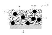
- FIG. 3 is a cross-sectional view of the positive electrode 10.
- the positive electrode active material 21 in the manufacturing process of the positive electrode 10, the positive electrode active material 21 (see FIG. 3) and the binder are dry-mixed without using a solvent, and the solid content concentration is substantially 100%.
- the positive electrode mixture 20 of the above is produced.
- the dry mixing is a method in which the positive electrode active material 21 and the binder are mixed in a state where the solid content concentration is substantially 100% without using a solvent. It is also possible to add a positive electrode active material, a conductive material other than the binder, and the like at the time of dry mixing. Even when a material other than the positive electrode active material and the binder is added, the solid content concentration in the dry mixture is substantially 100%.
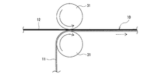
- the positive electrode mixture sheet 12 is produced by rolling the positive electrode mixture 20 and forming it into a sheet. Then, as shown in FIG. 2, the laminate of the core material 11 and the positive electrode mixture sheet 12 is hot-pressed to join the positive electrode mixture sheet 12 to the surface of the core material 11.
- the positive electrode 10 in which the positive electrode mixture layer made of the positive electrode mixture sheet 12 is provided on the surface of the core material 11 is manufactured.
- the positive electrode mixture sheet 12 includes a fibrous first binder 22 and a particle second binder 23.
- the positive electrode 10 includes a core material 11 and a positive electrode mixture sheet 12 bonded to the surface of the core material 11.
- the positive electrode mixture sheet 12 is preferably provided on both sides of the core material 11.
- the positive electrode mixture sheet 12 includes a positive electrode active material 21, a fibrous first binder 22, and a particle-like second binder 23.
- the positive electrode 10 may be a long electrode plate constituting a wound electrode body, or a rectangular electrode plate constituting a laminated electrode body.
- the positive electrode 10 is manufactured by sticking the positive electrode mixture sheet 12 to the core material 11 and then cutting the positive electrode 10 into a predetermined shape and dimensions.
- a metal foil having a thickness of 5 to 20 ⁇ m is used for the core material 11.
- An example of the metal foil constituting the core material 11 is a metal foil containing aluminum, preferably aluminum as a main component (a component having the highest mass ratio), and iron, manganese, copper, magnesium, zirconium, and silicon. , Chromium, titanium, and an aluminum alloy foil containing at least one metal selected from nickel.
- the positive electrode mixture sheet 12 is provided on the surface of the core material 11 and constitutes the mixture layer of the positive electrode 10.
- the positive electrode mixture sheet 12 contains the fibrous first binder 22 and the particulate second binder 23 as binders, and is, for example, 30 to 120 ⁇ m, preferably 50 to 100 ⁇ m. Has thickness.
- the fibrous first binder 22 the positive electrode mixture 20 can be rolled and formed into a sheet. Further, by using the second binder 23 together, the bonding force of the positive electrode mixture sheet 12 to the core material 11 is improved.
- the positive electrode mixture sheet 12 preferably contains the conductive material 24 in order to improve the electron conductivity.
- the conductive material 24 include carbon materials such as carbon black, acetylene black, ketjen black, and graphite.
- the content of the conductive material 24 is, for example, 0.5 to 5% by mass with respect to the mass of the positive electrode mixture sheet 12.
- An example of the volume-based median diameter (D50) of the conductive material 24 is 0.05 to 1 ⁇ m.
- the positive electrode mixture sheet 12 is composed mainly of the positive electrode active material 21.
- the content of the positive electrode active material 21 is preferably 85 to 99% by mass, more preferably 90 to 98% by mass, based on the mass of the positive electrode mixture sheet 12.
- the D50 of the positive electrode active material 21 is, for example, 1 to 30 ⁇ m, preferably 2 to 15 ⁇ m, and more preferably 3 to 15 ⁇ m.
- the positive electrode active material 21 and the conductive material 24 D50 are measured using a laser diffraction type particle size distribution measuring device (manufactured by HORIBA, Ltd., LA-920) using water as a dispersion medium.
- a lithium transition metal composite oxide is generally used as the positive electrode active material 21.
- Metal elements contained in the lithium transition metal composite oxide include Ni, Co, Mn, Al, B, Mg, Ti, V, Cr, Fe, Cu, Zn, Ga, Sr, Zr, Nb, In and Sn. , Ta, W and the like. Above all, it is preferable to contain at least one of Ni, Co and Mn.
- suitable composite oxides include lithium transition metal composite oxides containing Ni, Co and Mn, and lithium transition metal composite oxides containing Ni, Co and Al.
- the first binder 22 adheres to the particle surface of the positive electrode active material 21 and is entangled with the positive electrode active material 21. In other words, the positive electrode active material 21 is held by the first binder 22 that exists in a mesh shape, and the sheet shape is maintained.
- the first binder 22 is obtained, for example, by fibrillating PTFE particles containing polytetrafluoroethylene (PTFE) as a main component.
- the first binder 22 may be composed of only PTFE, or may contain a resin component other than PTFE as long as the object of the present disclosure is not impaired.
- the content of the first binder 22 is, for example, 0.05 to 10% by mass, preferably 0.1 to 8% by mass, and more preferably 0.2 to 0.2 to the mass of the positive electrode mixture sheet 12. It is 5% by mass.
- the second binder 23 contains polyvinylidene fluoride (PVdF) as a main component, and has a volume-based median diameter (D50) of 50 ⁇ m or less.
- the D50 of the second binder 23 is measured using a laser diffraction type particle size distribution measuring device using water as a dispersion medium, similarly to the positive electrode active material 21 and the like.
- PVdF is not fibrillated in the process of producing the positive electrode mixture 20, and the state of particles is maintained.
- the second binder 23 may be composed of only PVdF, and may contain a resin component other than PVdF as long as the object of the present disclosure is not impaired.
- the second binder 23 will be described as being PVdF particles.
- PVdF particles having a D50 of 50 ⁇ m or less are used as the second binder 23.
- the bonding strength of the positive electrode mixture sheet 12 to the core material 11 is specifically improved, and the positive electrode mixture sheet 12 The peel strength is greatly improved. Even if PVdF particles having a D50 of more than 50 ⁇ m are used, the effect of improving the bonding force is not substantially obtained, and the peel strength hardly changes as compared with the case where only the first binder 22 is used as the binder. ..
- the D50 of the second binder 23 is more preferably 40 ⁇ m or less, and particularly preferably 30 ⁇ m or less.
- the lower limit of D50 is not particularly limited, but is preferably 0.1 ⁇ m, more preferably 0.5 ⁇ m, and particularly preferably 1 ⁇ m.
- An example of a suitable range of D50 for the second binder 23 is 0.5-40 ⁇ m, or 1-30 ⁇ m. In this case, the bonding force of the positive electrode mixture sheet 12 with respect to the core material 11 is more remarkably improved.
- the D50 of the second binder 23 can be controlled within a target range by, for example, adjusting the polymerization conditions of PVdF and pulverizing the polymerized PVdF.
- the content of the second binder 23 is preferably less than the content of the first binder 22.
- the first binder 22: the second binder 23 1.5: 1 to 10: 1, or 2: 1 to 8: 1, or 3: 1 to 7: 1.
- the content of the second binder 23 is, for example, 0.1 to 5% by mass, preferably 0.2 to 4% by mass, and more preferably 0.5 to 0.5% by mass with respect to the mass of the positive electrode mixture sheet 12. It is 3% by mass. In this case, the peel strength of the positive electrode mixture sheet 12 can be efficiently improved while suppressing the increase in the electrode plate resistance.
- the positive electrode active material 21 may be embedded in the core material 11.
- the maximum biting depth D of the positive electrode active material 21 is, for example, 30% or more of the thickness of the core material 11, and as a specific example, 6 ⁇ m or more.
- the biting depth D of the positive electrode active material 21 means a length along the thickness direction of the core material 11 from the surface of the core material 11 to the most bitten portion of the positive electrode active material 21.
- the bite depth D can be measured by observing the cross section of the positive electrode 10 using SEM.
- the maximum biting depth D can be controlled by, for example, the softening temperature of the core material 11, the heating temperature in the heat pressing step described later, and the pressing pressure.
- the content of the second binder 23 in the first region is defined.
- the difference (ab) between (a) and the content (b) of the second binder 23 in the second region is preferably within the range of ⁇ 5%.
- the contents (a) and (b) may be substantially the same.
- the second binder 23 is not unevenly distributed on a part of the positive electrode mixture sheet 12, but is evenly present on the entire sheet. Such a uniform distribution of the binder can be realized by a dry method in which migration of the binder does not occur.
- the difference (A) between the content (A) of the first binder 22 in the first region and the content (B) of the first binder 22 in the second region. -B) is preferably in the range of ⁇ 5%.
- the concentration distribution of PVdF particles in the positive electrode mixture sheet 12 is measured by the following method. (1) The positive electrode is immersed in an alkaline solution to polyene PVdF in the positive electrode mixture sheet. (2) PVdF in the positive electrode mixture sheet treated in (1) is dyed with bromine Br. (3) The cross section of the positive electrode containing the stained PVdF is measured with an electron probe microanalyzer (EPMA) to obtain the concentration distribution of Br, which is used as the concentration distribution of PVdF.
- EPMA electron probe microanalyzer
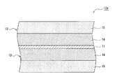
- FIG. 4 is a cross-sectional view of the positive electrode mixture sheet 13 which is another example of the embodiment.
- the positive electrode mixture sheet 13 includes a first sheet 14 including a positive electrode active material 21, a first binder 22, a second binder 23, and a conductive material 24, and a positive electrode active material 21. It has a multi-layer structure including a first binder 22 and a second sheet 15 including a conductive material 24 and substantially no second binder 23, and from the core material 11 side, the first sheet 14 , The second sheet 15 is arranged in this order. According to the positive electrode mixture sheet 13, the peel strength of the positive electrode mixture sheet 13 can be efficiently improved while suppressing an increase in electrode plate resistance.
- Both the first sheet 14 and the second sheet 15 are preferably produced by a dry method, and are bonded before the heat pressing step or the heat pressing described later to form a positive electrode mixture sheet 13.
- the thickness of each sheet is not particularly limited, and each sheet may have substantially the same thickness.
- the thickness of the first sheet 14 may be thinner than the thickness of the second sheet 15.
- the thickness of the second sheet 15 may be thinner than the thickness of the first sheet 14.
- An example of the thickness of each sheet is 30 to 60 ⁇ m.
- the content of each component in the first sheet 14 is, for example, the same as in the case of the positive electrode mixture sheet 12. Since the second sheet 15 does not substantially contain the second binder 23, the content of at least one of the positive electrode active material 21, the first binder 22, and the conductive material 24 is compared with that of the first sheet 14. Can be increased.
- the negative electrode includes a core material made of metal foil and a negative electrode mixture layer provided on the surface of the core material. Copper foil is generally used as the core material of the negative electrode.
- a conventionally known electrode plate manufactured by a wet method may be used, or a electrode plate provided with a negative electrode mixture sheet manufactured by a dry method may be used.
- the negative electrode may include a fibrous first binder and a negative electrode mixture sheet containing a particle-like second binder, and may have the same configuration as the above-mentioned positive electrode 10.
- the negative electrode active material for example, natural graphite such as scaly graphite, massive graphite, earthy graphite, carbon-based active material such as artificial graphite such as massive artificial graphite (MAG) and graphitized mesophase carbon microbeads (MCMB) are used. Be done. Further, as the negative electrode active material, a Si-based active material that alloys with lithium may be used. Since the carbon-based active material has higher electron conductivity than the positive electrode active material 21, the negative electrode does not have to contain the conductive material 24.
- natural graphite such as scaly graphite, massive graphite, earthy graphite
- carbon-based active material such as artificial graphite such as massive artificial graphite (MAG) and graphitized mesophase carbon microbeads (MCMB) are used. Be done.
- a Si-based active material that alloys with lithium may be used. Since the carbon-based active material has higher electron conductivity than the positive electrode active material 21, the negative electrode does not have to contain
- the non-aqueous electrolyte secondary battery which is an example of the embodiment, includes an electrode body in which the above-mentioned positive electrode 10 and the negative electrode are laminated via a separator, a non-aqueous electrolyte, and an exterior body for accommodating them.
- the electrode body may be either a wound type electrode body or a laminated type electrode body.
- Examples of the exterior body include a cylindrical outer can, a square outer can, a coin-shaped outer can, and an outer body made of an aluminum laminated sheet.
- the non-aqueous electrolyte contains a non-aqueous solvent and an electrolyte salt dissolved in the non-aqueous solvent.
- the non-aqueous solvent for example, esters, ethers, nitriles, amides, and a mixed solvent of two or more of these are used.
- the non-aqueous solvent may contain a halogen substituent in which at least a part of hydrogen in these solvents is substituted with a halogen atom such as fluorine.
- the electrolyte salt for example, a lithium salt such as LiPF 6 is used.
- the electrolyte is not limited to the liquid electrolyte, and may be a solid electrolyte.
- the positive electrode active material 21, PTFE particles, PVdF particles (second binder 23), and the conductive material 24 are charged into the mixer 40. Then, while fibrillating the PTFE particles, these materials are mixed to prepare an electrode mixture 20 (hereinafter, this step is referred to as a "first step").
- the electrode mixture sheet 20 is produced by rolling the electrode mixture 20 into a sheet shape (hereinafter, this step is referred to as a “second step”). ..
- This manufacturing process is a dry method in which the electrode 10 is manufactured using the electrode mixture 20 having a solid content concentration of substantially 100%.
- the PTFE particles for example, particles having a D50 of 5 to 100 ⁇ m are used.
- the mixing treatment can be performed in a short time with a relatively low shearing force, the positive electrode active material 21 has less particle cracking, the constituent materials have good dispersibility, and the positive electrode mixture sheet 12 having high breaking strength is obtained.
- the PTFE particles are fibrillated in the first step to become the fibrous first binder 22.
- PVdF particles having a D50 of 50 ⁇ m or less, preferably 0.5 to 40 ⁇ m or 1 to 30 ⁇ m are used. PVdF is not fibrillated in the first step and maintains the particle shape and D50 before mixing.
- a mechanical stirring type mixer Although a conventionally known device can be used for the mixer 40, it is preferable to use a mechanical stirring type mixer.
- a suitable mixer 40 include a cutter mill, a pin mill, a bead mill, and a fine particle compounding device (shearing between a rotor having a special shape that rotates at high speed inside a tank and a collision plate), which are devices capable of applying a mechanical shearing force.
- a device that produces force a granulator, a twin-screw extrusion kneader, a kneader such as a planetary mixer, and the like.
- a cutter mill, a fine particle compounding device, a granulator, or a twin-screw extrusion kneader is preferable.
- the electrode mixture 20 is rolled using two rolls 30 and formed into a sheet shape.
- the two rolls 30 are arranged with a predetermined gap and rotate in the same direction.
- the electrode mixture 20 is compressed by the two rolls 30 and stretched into a sheet shape.
- the two rolls 30, for example, have the same roll diameter.
- the obtained electrode mixture sheet 12 may be passed through the gap between the two rolls 30 a plurality of times, or may be stretched once or more using other rolls having different roll diameters, peripheral speeds, gaps, and the like. Alternatively, the roll may be heated to heat press the electrode mixture sheet 12.
- the thickness of the electrode mixture sheet 12 can be controlled by, for example, the gap between the two rolls 30, the peripheral speed, the number of stretching treatments, and the like.
- the peripheral speed ratio of the two rolls 30 is preferably 2.5 times or more, and may be 3 times or more.
- the peripheral speed ratio of the two rolls 30 is, for example, 1: 3.
- FIG. 2 shows a state in which the electrode mixture sheet 12 is bonded to only one surface of the core material 11, but it is preferable that the electrode mixture sheet 12 is bonded to both surfaces of the core material 11.
- the two electrode mixture sheets 12 may be bonded to both sides of the core material 11 at the same time, and after one sheet is bonded to one surface of the core material 11, the other sheet is bonded to the other surface. May be good.
- the electrode mixture sheet 12 is attached to the surface of the core material 11 using two rolls 31.
- the two rolls 31 have, for example, the same roll diameter, are arranged with a predetermined gap, and rotate in the same direction at the same peripheral speed. It is preferable that the two rolls 31 are heated to a predetermined temperature and applied a predetermined pressure.
- the electrode 10 manufactured through the above steps has a positive electrode mixture sheet 12 having a high peel strength that is firmly bonded to the core material 11 as shown in Examples described later.
- Example 1 [Preparation of positive electrode mixture]
- a mixer (Osaka Chemical Co., Ltd., Wonder Crusher) containing a positive electrode active material, PTFE particles having a D50 of 10 ⁇ m, PVdF particles having a D50 of 25 ⁇ m, and acetylene black at a mass ratio of 100: 4: 0.8: 0.9. ) was used for mixing.
- the PTFE particles were fibrillated, and a positive electrode mixture in which the active material, fibrous PTFE, PVdF particles, and acetylene black were uniformly dispersed was obtained.
- the obtained positive electrode mixture has a solid content concentration of 100%.
- the obtained positive electrode mixture was passed between two rolls and rolled to prepare a positive electrode mixture sheet.
- the peripheral speed ratio of the two rolls was set to 1: 3, and stretching treatment was performed a plurality of times to adjust the thickness of the positive electrode mixture sheet to 130 ⁇ m.
- the obtained positive electrode mixture sheet is placed on the surface of the core material, and the laminate of the positive electrode mixture sheet and the core material is hot-pressed (press pressure: 0.2 [press pressure: 0.2] using two rolls heated to 200 ° C. t / cm]).
- press pressure 0.2 [press pressure: 0.2] using two rolls heated to 200 ° C. t / cm]
- a positive electrode in which the positive electrode mixture sheet was firmly bonded to the surface of the core material was obtained.
- An aluminum alloy foil having a thickness of 15 ⁇ m was used as the core material.
- the peel strength of the positive electrode mixture sheet was evaluated by the following method, and the evaluation results are shown in Table 1 together with D50 of PVdF particles (second binder).
- Example 2 A positive electrode was prepared in the same manner as in Example 1 except that PVdF particles having a D50 of 10 ⁇ m were used as the second binder, and the peel strength was evaluated.
- a positive electrode was prepared in the same manner as in Example 1 except that the second binder was not used, and the peel strength was evaluated.
- Example 2 A positive electrode was prepared in the same manner as in Example 1 except that PVdF particles having a D50 of 150 ⁇ m were used as the second binder, and the peel strength was evaluated.
- the positive electrodes of the examples have significantly higher peel strength than the positive electrodes of the comparative examples, and it can be seen that the positive electrode mixture sheet is strongly bonded to the core material.
- the positive electrode of Comparative Example 2 had the same peel strength as the positive electrode of Comparative Example 1 which did not contain PVdF particles even though it contained PVdF particles as the second binder. That is, the D50 of the second binder has a great influence on the peel strength of the positive electrode mixture sheet.
- the particle size of the PVdF particles is large, the PVdF particles do not melt in a short heat pressing process and cannot exhibit sufficient adhesive force, and even if they do melt, they have a very large particle size with respect to the active material particles.
- the amount of addition is small, it is considered that a sufficient adhesion area with the active material particles cannot be secured, which is a factor that the peel strength is not improved.
- the peel strength of the positive electrode mixture sheet is specifically improved only when the second binder whose D50 is adjusted to a predetermined range is used together with the fibrous first binder.
- Table 1 the evaluation results using the second binder having a D50 of 10 ⁇ m and 25 ⁇ m are shown. High peel strength can be obtained when the D50 is 50 ⁇ m or less, preferably in the range of 1 to 30 ⁇ m.
- Positive electrode 11 Core material 12, 13 Positive electrode mixture sheet 14 First sheet 15 Second sheet 20 Positive electrode mixture 21 Positive electrode active material 22 First binder 23 Second binder 24 Conductive material 30, 31 Roll 40 Mixer
Landscapes
- Chemical & Material Sciences (AREA)
- Chemical Kinetics & Catalysis (AREA)
- Electrochemistry (AREA)
- General Chemical & Material Sciences (AREA)
- Engineering & Computer Science (AREA)
- Manufacturing & Machinery (AREA)
- Materials Engineering (AREA)
- Battery Electrode And Active Subsutance (AREA)
- Secondary Cells (AREA)
Priority Applications (4)
| Application Number | Priority Date | Filing Date | Title |
|---|---|---|---|
| EP21776906.6A EP4131458A4 (en) | 2020-03-24 | 2021-01-19 | Electrode for secondary batteries and method for producing same |
| US17/911,507 US12555793B2 (en) | 2020-03-24 | 2021-01-19 | Electrode for secondary batteries and method for producing same |
| CN202180021893.6A CN115336030A (zh) | 2020-03-24 | 2021-01-19 | 二次电池用电极及其制造方法 |
| JP2022509312A JPWO2021192541A1 (https=) | 2020-03-24 | 2021-01-19 |
Applications Claiming Priority (2)
| Application Number | Priority Date | Filing Date | Title |
|---|---|---|---|
| JP2020-052754 | 2020-03-24 | ||
| JP2020052754 | 2020-03-24 |
Publications (1)
| Publication Number | Publication Date |
|---|---|
| WO2021192541A1 true WO2021192541A1 (ja) | 2021-09-30 |
Family
ID=77890100
Family Applications (1)
| Application Number | Title | Priority Date | Filing Date |
|---|---|---|---|
| PCT/JP2021/001563 Ceased WO2021192541A1 (ja) | 2020-03-24 | 2021-01-19 | 二次電池用電極およびその製造方法 |
Country Status (5)
| Country | Link |
|---|---|
| US (1) | US12555793B2 (https=) |
| EP (1) | EP4131458A4 (https=) |
| JP (1) | JPWO2021192541A1 (https=) |
| CN (1) | CN115336030A (https=) |
| WO (1) | WO2021192541A1 (https=) |
Cited By (17)
| Publication number | Priority date | Publication date | Assignee | Title |
|---|---|---|---|---|
| WO2023167296A1 (ja) * | 2022-03-02 | 2023-09-07 | ダイキン工業株式会社 | 二次電池用合剤、二次電池用合剤シート、二次電池用合剤シートの製造方法及び二次電池 |
| JP2024036847A (ja) * | 2022-09-06 | 2024-03-18 | トヨタ自動車株式会社 | リチウムイオン電池 |
| WO2024154806A1 (ja) | 2023-01-18 | 2024-07-25 | ダイキン工業株式会社 | 電気化学デバイス用合剤自立膜、電極、及び、電気化学デバイス |
| WO2024154777A1 (ja) | 2023-01-18 | 2024-07-25 | ダイキン工業株式会社 | 電気化学デバイス用合剤、電気化学デバイス用合剤シート、電極、及び、電気化学デバイス |
| WO2024154803A1 (ja) | 2023-01-18 | 2024-07-25 | ダイキン工業株式会社 | テトラフルオロエチレン系ポリマー組成物、電気化学デバイス用バインダー、電極合剤、電極、及び、二次電池 |
| WO2024154810A1 (ja) | 2023-01-18 | 2024-07-25 | ダイキン工業株式会社 | テトラフルオロエチレン系ポリマー組成物、電気化学デバイス用バインダー、電極合剤、電極、及び、二次電池 |
| WO2024154807A1 (ja) | 2023-01-18 | 2024-07-25 | ダイキン工業株式会社 | テトラフルオロエチレン系ポリマー組成物、電気化学デバイス用バインダー、電極合剤、電極、及び、二次電池 |
| WO2024154773A1 (ja) | 2023-01-18 | 2024-07-25 | ダイキン工業株式会社 | テトラフルオロエチレン系ポリマー組成物、電気化学デバイス用バインダー、電極合剤、電極、及び、二次電池 |
| WO2024154786A1 (ja) | 2023-01-18 | 2024-07-25 | ダイキン工業株式会社 | 電気化学デバイス用合剤、電気化学デバイス用合剤シート、電極、及び、電気化学デバイス |
| WO2024154809A1 (ja) | 2023-01-18 | 2024-07-25 | ダイキン工業株式会社 | フッ素系ポリマー組成物、電気化学デバイス用バインダー、電極合剤、電極、及び、二次電池 |
| WO2024154805A1 (ja) | 2023-01-18 | 2024-07-25 | ダイキン工業株式会社 | テトラフルオロエチレン系ポリマー組成物、固体二次電池用バインダー、電解質層用合剤、電極合剤、電極、及び、固体二次電池 |
| JP2024533404A (ja) * | 2021-10-05 | 2024-09-12 | エルジー エナジー ソリューション リミテッド | 電極、これを含む二次電池、及びこの製造方法 |
| WO2025005273A1 (ja) | 2023-06-30 | 2025-01-02 | ダイキン工業株式会社 | ポリテトラフルオロエチレン組成物、電気化学デバイス用バインダー、電極合剤、電極、及び、二次電池 |
| WO2025005277A1 (ja) | 2023-06-30 | 2025-01-02 | ダイキン工業株式会社 | ポリテトラフルオロエチレン、電気化学デバイス用バインダー、電極合剤、電極、及び、二次電池 |
| JP2025504009A (ja) * | 2022-01-28 | 2025-02-06 | エルジー エナジー ソリューション リミテッド | 二次電池 |
| KR20250127336A (ko) | 2023-01-18 | 2025-08-26 | 다이킨 고교 가부시키가이샤 | 테트라플루오로에틸렌계 폴리머, 전기 화학 디바이스용 바인더, 전극 합제, 전극, 및 이차 전지 |
| KR102957153B1 (ko) * | 2021-10-05 | 2026-04-24 | 주식회사 엘지에너지솔루션 | 전극, 이를 포함하는 이차전지, 및 이의 제조 방법 |
Families Citing this family (5)
| Publication number | Priority date | Publication date | Assignee | Title |
|---|---|---|---|---|
| JP7668475B2 (ja) * | 2020-03-11 | 2025-04-25 | パナソニックIpマネジメント株式会社 | 電極の製造方法および電極合材 |
| EP4120383A4 (en) * | 2020-03-11 | 2024-07-31 | Panasonic Intellectual Property Management Co., Ltd. | ELECTRODE FOR SECONDARY BATTERY AND PRODUCTION METHOD THEREFOR |
| CN117638066A (zh) * | 2022-08-16 | 2024-03-01 | 通用汽车环球科技运作有限责任公司 | 用于厚电极的结晶材料添加剂 |
| CN117497684A (zh) * | 2023-10-30 | 2024-02-02 | 惠州亿纬锂能股份有限公司 | 一种纤维化蓬松粉体及其制备方法和锂离子电池 |
| EP4567909A1 (en) * | 2023-10-30 | 2025-06-11 | Eve Energy Co., Ltd. | Fibrillated fluffy power, method of manufacturing the same, and lithium-ion battery technical field |
Citations (9)
| Publication number | Priority date | Publication date | Assignee | Title |
|---|---|---|---|---|
| JPH117952A (ja) * | 1997-06-05 | 1999-01-12 | Alcatel Alsthom Co General Electricite | ペースト式ニッケル電極 |
| JPH11273665A (ja) * | 1998-03-26 | 1999-10-08 | Sanyo Electric Co Ltd | 非水電解液電池およびその製造方法 |
| JP2000149954A (ja) * | 1998-11-11 | 2000-05-30 | Sanyo Electric Co Ltd | 非水電解液電池およびその製造方法 |
| JP2001307716A (ja) * | 2000-02-16 | 2001-11-02 | Nisshinbo Ind Inc | 多層電極構造体、それを用いた電池、電気二重層キャパシター及びそれらの製造方法 |
| JP2011258333A (ja) * | 2010-06-07 | 2011-12-22 | Asahi Glass Co Ltd | 二次電池用電極コンポジットの製造方法、二次電池用電極および二次電池 |
| JP2013065478A (ja) | 2011-09-19 | 2013-04-11 | Toyota Motor Corp | リチウムイオン二次電池の製造方法 |
| WO2015107896A1 (ja) * | 2014-01-16 | 2015-07-23 | 日本ゼオン株式会社 | 二次電池電極用バインダー組成物、二次電池電極用スラリー組成物、二次電池用電極および二次電池 |
| JP2019216101A (ja) * | 2014-04-18 | 2019-12-19 | マックスウェル テクノロジーズ インコーポレイテッド | エネルギー貯蔵装置の乾式電極とその製造方法 |
| US20200028156A1 (en) * | 2018-02-06 | 2020-01-23 | Navitas Systems, Llc | Dry process formation of solid state lithium ion cell |
Family Cites Families (18)
| Publication number | Priority date | Publication date | Assignee | Title |
|---|---|---|---|---|
| JP3067544B2 (ja) * | 1994-10-05 | 2000-07-17 | 松下電器産業株式会社 | リチウム二次電池用正極およびその製造法 |
| US5952123A (en) * | 1995-07-04 | 1999-09-14 | Matsushita Electric Industrial Co., Ltd. | Electrode plates for lead-acid battery and their manufacturing method |
| JPH10188992A (ja) * | 1996-12-24 | 1998-07-21 | Sony Corp | 非水電解液電池 |
| DE60128411T2 (de) | 2000-02-16 | 2008-01-17 | Nisshinbo Industries, Inc. | Mehrschichtelektrodenstruktur und Verfahren für ihre Herstellung |
| TW550848B (en) * | 2001-02-16 | 2003-09-01 | Nisshin Spinning | Multi-layered electrode structural body, cell using same, dual-layer capacitor and manufacturing method for same |
| JP3813455B2 (ja) | 2001-03-22 | 2006-08-23 | 三洋電機株式会社 | 電気エネルギー蓄積デバイスの製造方法 |
| JP4233276B2 (ja) * | 2002-06-27 | 2009-03-04 | 三井・デュポンフロロケミカル株式会社 | 電極材料用結着剤 |
| JP2005063825A (ja) * | 2003-08-13 | 2005-03-10 | Nippon Zeon Co Ltd | 非水電解質二次電池正極用スラリー組成物 |
| JP2005174631A (ja) * | 2003-12-09 | 2005-06-30 | Matsushita Electric Ind Co Ltd | 非水電解質二次電池用正極板および非水電解質二次電池 |
| JP5315595B2 (ja) * | 2005-09-15 | 2013-10-16 | 日産自動車株式会社 | 電池用電極およびその製造方法 |
| WO2013148051A1 (en) * | 2012-03-30 | 2013-10-03 | Linda Zhong | Electrode for energy storage devices and method for making same |
| US20150147660A1 (en) | 2013-11-26 | 2015-05-28 | Samsung Electronics Co., Ltd. | All solid secondary battery and method of preparing all solid secondary battery |
| JP6262503B2 (ja) * | 2013-11-26 | 2018-01-17 | 三星電子株式会社Samsung Electronics Co.,Ltd. | 全固体二次電池および全固体二次電池の製造方法 |
| JP6338104B2 (ja) * | 2014-08-06 | 2018-06-06 | 株式会社豊田自動織機 | リチウムイオン二次電池用正極およびその製造方法ならびにリチウムイオン二次電池およびその製造方法 |
| CN104530276B (zh) | 2014-12-30 | 2017-09-29 | 山东华夏神舟新材料有限公司 | 一种锂电池粘结剂专用聚偏氟乙烯的制备方法 |
| JP7029922B2 (ja) * | 2017-10-10 | 2022-03-04 | 日産自動車株式会社 | 非水電解質二次電池用電極の製造方法 |
| CN109004171A (zh) * | 2018-02-26 | 2018-12-14 | 宁德新能源科技有限公司 | 一种正极极片和锂离子电池 |
| KR20250096871A (ko) * | 2018-05-02 | 2025-06-27 | 테슬라, 인크. | 규소 함유 건식 애노드 필름용 조성물 및 방법 |
-
2021
- 2021-01-19 JP JP2022509312A patent/JPWO2021192541A1/ja active Pending
- 2021-01-19 EP EP21776906.6A patent/EP4131458A4/en active Pending
- 2021-01-19 WO PCT/JP2021/001563 patent/WO2021192541A1/ja not_active Ceased
- 2021-01-19 CN CN202180021893.6A patent/CN115336030A/zh active Pending
- 2021-01-19 US US17/911,507 patent/US12555793B2/en active Active
Patent Citations (9)
| Publication number | Priority date | Publication date | Assignee | Title |
|---|---|---|---|---|
| JPH117952A (ja) * | 1997-06-05 | 1999-01-12 | Alcatel Alsthom Co General Electricite | ペースト式ニッケル電極 |
| JPH11273665A (ja) * | 1998-03-26 | 1999-10-08 | Sanyo Electric Co Ltd | 非水電解液電池およびその製造方法 |
| JP2000149954A (ja) * | 1998-11-11 | 2000-05-30 | Sanyo Electric Co Ltd | 非水電解液電池およびその製造方法 |
| JP2001307716A (ja) * | 2000-02-16 | 2001-11-02 | Nisshinbo Ind Inc | 多層電極構造体、それを用いた電池、電気二重層キャパシター及びそれらの製造方法 |
| JP2011258333A (ja) * | 2010-06-07 | 2011-12-22 | Asahi Glass Co Ltd | 二次電池用電極コンポジットの製造方法、二次電池用電極および二次電池 |
| JP2013065478A (ja) | 2011-09-19 | 2013-04-11 | Toyota Motor Corp | リチウムイオン二次電池の製造方法 |
| WO2015107896A1 (ja) * | 2014-01-16 | 2015-07-23 | 日本ゼオン株式会社 | 二次電池電極用バインダー組成物、二次電池電極用スラリー組成物、二次電池用電極および二次電池 |
| JP2019216101A (ja) * | 2014-04-18 | 2019-12-19 | マックスウェル テクノロジーズ インコーポレイテッド | エネルギー貯蔵装置の乾式電極とその製造方法 |
| US20200028156A1 (en) * | 2018-02-06 | 2020-01-23 | Navitas Systems, Llc | Dry process formation of solid state lithium ion cell |
Non-Patent Citations (1)
| Title |
|---|
| See also references of EP4131458A4 |
Cited By (28)
| Publication number | Priority date | Publication date | Assignee | Title |
|---|---|---|---|---|
| JP2024533404A (ja) * | 2021-10-05 | 2024-09-12 | エルジー エナジー ソリューション リミテッド | 電極、これを含む二次電池、及びこの製造方法 |
| KR102957153B1 (ko) * | 2021-10-05 | 2026-04-24 | 주식회사 엘지에너지솔루션 | 전극, 이를 포함하는 이차전지, 및 이의 제조 방법 |
| EP4391102A4 (en) * | 2021-10-05 | 2025-07-02 | Lg Energy Solution Ltd | ELECTRODE, SECONDARY BATTERY COMPRISING SAME AND METHOD FOR MANUFACTURING SAME |
| US12603291B2 (en) | 2022-01-28 | 2026-04-14 | Lg Energy Solution, Ltd. | Secondary battery |
| US12580197B2 (en) | 2022-01-28 | 2026-03-17 | Lg Energy Solution, Ltd. | Secondary battery |
| JP2025504009A (ja) * | 2022-01-28 | 2025-02-06 | エルジー エナジー ソリューション リミテッド | 二次電池 |
| JP2023129368A (ja) * | 2022-03-02 | 2023-09-14 | ダイキン工業株式会社 | 二次電池用合剤、二次電池用合剤シート、二次電池用合剤シートの製造方法及び二次電池 |
| JP7364972B2 (ja) | 2022-03-02 | 2023-10-19 | ダイキン工業株式会社 | 二次電池用合剤、二次電池用合剤シート、二次電池用合剤シートの製造方法及び二次電池 |
| EP4489138A4 (en) * | 2022-03-02 | 2026-02-25 | Daikin Ind Ltd | SECONDARY BATTERY MIX, SECONDARY BATTERY MIX SHEET, METHOD FOR MANUFACTURING SECONDARY BATTERY MIX SHEET AND SECONDARY BATTERY |
| WO2023167296A1 (ja) * | 2022-03-02 | 2023-09-07 | ダイキン工業株式会社 | 二次電池用合剤、二次電池用合剤シート、二次電池用合剤シートの製造方法及び二次電池 |
| JP2024036847A (ja) * | 2022-09-06 | 2024-03-18 | トヨタ自動車株式会社 | リチウムイオン電池 |
| JP7771900B2 (ja) | 2022-09-06 | 2025-11-18 | トヨタ自動車株式会社 | リチウムイオン電池 |
| KR20250129810A (ko) | 2023-01-18 | 2025-08-29 | 다이킨 고교 가부시키가이샤 | 전기 화학 디바이스용 합제 자립막, 전극, 및 전기 화학 디바이스 |
| KR20250128385A (ko) | 2023-01-18 | 2025-08-27 | 다이킨 고교 가부시키가이샤 | 테트라플루오로에틸렌계 폴리머 조성물, 전기 화학 디바이스용 바인더, 전극 합제, 전극, 및 이차 전지 |
| WO2024154806A1 (ja) | 2023-01-18 | 2024-07-25 | ダイキン工業株式会社 | 電気化学デバイス用合剤自立膜、電極、及び、電気化学デバイス |
| WO2024154777A1 (ja) | 2023-01-18 | 2024-07-25 | ダイキン工業株式会社 | 電気化学デバイス用合剤、電気化学デバイス用合剤シート、電極、及び、電気化学デバイス |
| WO2024154809A1 (ja) | 2023-01-18 | 2024-07-25 | ダイキン工業株式会社 | フッ素系ポリマー組成物、電気化学デバイス用バインダー、電極合剤、電極、及び、二次電池 |
| WO2024154786A1 (ja) | 2023-01-18 | 2024-07-25 | ダイキン工業株式会社 | 電気化学デバイス用合剤、電気化学デバイス用合剤シート、電極、及び、電気化学デバイス |
| KR20250127336A (ko) | 2023-01-18 | 2025-08-26 | 다이킨 고교 가부시키가이샤 | 테트라플루오로에틸렌계 폴리머, 전기 화학 디바이스용 바인더, 전극 합제, 전극, 및 이차 전지 |
| WO2024154805A1 (ja) | 2023-01-18 | 2024-07-25 | ダイキン工業株式会社 | テトラフルオロエチレン系ポリマー組成物、固体二次電池用バインダー、電解質層用合剤、電極合剤、電極、及び、固体二次電池 |
| KR20250129106A (ko) | 2023-01-18 | 2025-08-28 | 다이킨 고교 가부시키가이샤 | 테트라플루오로에틸렌계 폴리머 조성물, 고체 이차 전지용 바인더, 전해질층용 합제, 전극 합제, 전극, 및 고체 이차 전지 |
| WO2024154773A1 (ja) | 2023-01-18 | 2024-07-25 | ダイキン工業株式会社 | テトラフルオロエチレン系ポリマー組成物、電気化学デバイス用バインダー、電極合剤、電極、及び、二次電池 |
| KR20250129778A (ko) | 2023-01-18 | 2025-08-29 | 다이킨 고교 가부시키가이샤 | 불소계 폴리머 조성물, 전기 화학 디바이스용 바인더, 전극 합제, 전극, 및 이차 전지 |
| WO2024154807A1 (ja) | 2023-01-18 | 2024-07-25 | ダイキン工業株式会社 | テトラフルオロエチレン系ポリマー組成物、電気化学デバイス用バインダー、電極合剤、電極、及び、二次電池 |
| WO2024154810A1 (ja) | 2023-01-18 | 2024-07-25 | ダイキン工業株式会社 | テトラフルオロエチレン系ポリマー組成物、電気化学デバイス用バインダー、電極合剤、電極、及び、二次電池 |
| WO2024154803A1 (ja) | 2023-01-18 | 2024-07-25 | ダイキン工業株式会社 | テトラフルオロエチレン系ポリマー組成物、電気化学デバイス用バインダー、電極合剤、電極、及び、二次電池 |
| WO2025005277A1 (ja) | 2023-06-30 | 2025-01-02 | ダイキン工業株式会社 | ポリテトラフルオロエチレン、電気化学デバイス用バインダー、電極合剤、電極、及び、二次電池 |
| WO2025005273A1 (ja) | 2023-06-30 | 2025-01-02 | ダイキン工業株式会社 | ポリテトラフルオロエチレン組成物、電気化学デバイス用バインダー、電極合剤、電極、及び、二次電池 |
Also Published As
| Publication number | Publication date |
|---|---|
| US12555793B2 (en) | 2026-02-17 |
| US20230108728A1 (en) | 2023-04-06 |
| EP4131458A4 (en) | 2024-07-24 |
| EP4131458A1 (en) | 2023-02-08 |
| CN115336030A (zh) | 2022-11-11 |
| JPWO2021192541A1 (https=) | 2021-09-30 |
Similar Documents
| Publication | Publication Date | Title |
|---|---|---|
| WO2021192541A1 (ja) | 二次電池用電極およびその製造方法 | |
| JP7742563B2 (ja) | 二次電池用電極およびその製造方法 | |
| JP7668475B2 (ja) | 電極の製造方法および電極合材 | |
| JP7804875B2 (ja) | 電極の製造方法 | |
| JP7716672B2 (ja) | Ptfe粉末、電極の製造方法、及び電極 | |
| JP7766284B2 (ja) | 電極、及び電極の製造方法 | |
| WO2023119814A1 (ja) | 電極、非水電解質二次電池、および電極の製造方法 | |
| JP7833660B2 (ja) | 電極 | |
| CN118891742A (zh) | 电极、非水电解质二次电池和电极的制造方法 | |
| JP7745184B2 (ja) | 電極、及び電極の製造方法 | |
| JP7833659B2 (ja) | 電極 | |
| EP4254540A1 (en) | Electrode and method for producing electrode | |
| WO2025164452A1 (ja) | 電極 | |
| CN116472620A (zh) | 电极以及电极的制造方法 | |
| CN120642071A (zh) | 电极的制造方法、电极和非水电解质二次电池 |
Legal Events
| Date | Code | Title | Description |
|---|---|---|---|
| 121 | Ep: the epo has been informed by wipo that ep was designated in this application |
Ref document number: 21776906 Country of ref document: EP Kind code of ref document: A1 |
|
| ENP | Entry into the national phase |
Ref document number: 2022509312 Country of ref document: JP Kind code of ref document: A |
|
| NENP | Non-entry into the national phase |
Ref country code: DE |
|
| ENP | Entry into the national phase |
Ref document number: 2021776906 Country of ref document: EP Effective date: 20221024 |
|
| WWG | Wipo information: grant in national office |
Ref document number: 17911507 Country of ref document: US |