WO2021192537A1 - 自動分析システム - Google Patents
自動分析システム Download PDFInfo
- Publication number
- WO2021192537A1 WO2021192537A1 PCT/JP2021/001437 JP2021001437W WO2021192537A1 WO 2021192537 A1 WO2021192537 A1 WO 2021192537A1 JP 2021001437 W JP2021001437 W JP 2021001437W WO 2021192537 A1 WO2021192537 A1 WO 2021192537A1
- Authority
- WO
- WIPO (PCT)
- Prior art keywords
- calibration
- quality control
- list
- analysis system
- request
- Prior art date
- Legal status (The legal status is an assumption and is not a legal conclusion. Google has not performed a legal analysis and makes no representation as to the accuracy of the status listed.)
- Ceased
Links
Images


Classifications
-
- G—PHYSICS
- G01—MEASURING; TESTING
- G01N—INVESTIGATING OR ANALYSING MATERIALS BY DETERMINING THEIR CHEMICAL OR PHYSICAL PROPERTIES
- G01N35/00—Automatic analysis not limited to methods or materials provided for in any single one of groups G01N1/00 - G01N33/00; Handling materials therefor
- G01N35/00584—Control arrangements for automatic analysers
- G01N35/00594—Quality control, including calibration or testing of components of the analyser
- G01N35/00613—Quality control
-
- G—PHYSICS
- G01—MEASURING; TESTING
- G01N—INVESTIGATING OR ANALYSING MATERIALS BY DETERMINING THEIR CHEMICAL OR PHYSICAL PROPERTIES
- G01N35/00—Automatic analysis not limited to methods or materials provided for in any single one of groups G01N1/00 - G01N33/00; Handling materials therefor
- G01N35/02—Automatic analysis not limited to methods or materials provided for in any single one of groups G01N1/00 - G01N33/00; Handling materials therefor using a plurality of sample containers moved by a conveyor system past one or more treatment or analysis stations
- G01N35/025—Automatic analysis not limited to methods or materials provided for in any single one of groups G01N1/00 - G01N33/00; Handling materials therefor using a plurality of sample containers moved by a conveyor system past one or more treatment or analysis stations having a carousel or turntable for reaction cells or cuvettes
-
- G—PHYSICS
- G01—MEASURING; TESTING
- G01N—INVESTIGATING OR ANALYSING MATERIALS BY DETERMINING THEIR CHEMICAL OR PHYSICAL PROPERTIES
- G01N35/00—Automatic analysis not limited to methods or materials provided for in any single one of groups G01N1/00 - G01N33/00; Handling materials therefor
- G01N35/00584—Control arrangements for automatic analysers
- G01N35/00594—Quality control, including calibration or testing of components of the analyser
- G01N35/00693—Calibration
-
- G—PHYSICS
- G01—MEASURING; TESTING
- G01N—INVESTIGATING OR ANALYSING MATERIALS BY DETERMINING THEIR CHEMICAL OR PHYSICAL PROPERTIES
- G01N35/00—Automatic analysis not limited to methods or materials provided for in any single one of groups G01N1/00 - G01N33/00; Handling materials therefor
- G01N35/00584—Control arrangements for automatic analysers
- G01N35/00722—Communications; Identification
- G01N2035/00891—Displaying information to the operator
- G01N2035/0091—GUI [graphical user interfaces]
-
- G—PHYSICS
- G01—MEASURING; TESTING
- G01N—INVESTIGATING OR ANALYSING MATERIALS BY DETERMINING THEIR CHEMICAL OR PHYSICAL PROPERTIES
- G01N35/00—Automatic analysis not limited to methods or materials provided for in any single one of groups G01N1/00 - G01N33/00; Handling materials therefor
- G01N35/02—Automatic analysis not limited to methods or materials provided for in any single one of groups G01N1/00 - G01N33/00; Handling materials therefor using a plurality of sample containers moved by a conveyor system past one or more treatment or analysis stations
- G01N35/04—Details of the conveyor system
- G01N2035/0401—Sample carriers, cuvettes or reaction vessels
- G01N2035/0412—Block or rack elements with a single row of samples
-
- G—PHYSICS
- G01—MEASURING; TESTING
- G01N—INVESTIGATING OR ANALYSING MATERIALS BY DETERMINING THEIR CHEMICAL OR PHYSICAL PROPERTIES
- G01N35/00—Automatic analysis not limited to methods or materials provided for in any single one of groups G01N1/00 - G01N33/00; Handling materials therefor
- G01N35/02—Automatic analysis not limited to methods or materials provided for in any single one of groups G01N1/00 - G01N33/00; Handling materials therefor using a plurality of sample containers moved by a conveyor system past one or more treatment or analysis stations
- G01N35/04—Details of the conveyor system
- G01N2035/0439—Rotary sample carriers, i.e. carousels
- G01N2035/0443—Rotary sample carriers, i.e. carousels for reagents
-
- G—PHYSICS
- G01—MEASURING; TESTING
- G01N—INVESTIGATING OR ANALYSING MATERIALS BY DETERMINING THEIR CHEMICAL OR PHYSICAL PROPERTIES
- G01N35/00—Automatic analysis not limited to methods or materials provided for in any single one of groups G01N1/00 - G01N33/00; Handling materials therefor
- G01N35/02—Automatic analysis not limited to methods or materials provided for in any single one of groups G01N1/00 - G01N33/00; Handling materials therefor using a plurality of sample containers moved by a conveyor system past one or more treatment or analysis stations
- G01N35/04—Details of the conveyor system
- G01N2035/0474—Details of actuating means for conveyors or pipettes
- G01N2035/0491—Position sensing, encoding; closed-loop control
- G01N2035/0493—Locating samples; identifying different tube sizes
Definitions
- the present invention relates to an automatic analysis system for analyzing a sample, and particularly to calibration and quality control.
- the automatic analysis system is used to measure the concentration of specific components contained in samples such as blood and urine. More specifically, the absorbance and the amount of luminescence of the reaction solution obtained by reacting the sample and the reagent are measured, and the concentration of the specific component is calculated from the measurement results such as the absorbance and the amount of luminescence and the calibration curve.
- a calibration curve is created by performing a calibration, which is a measurement using multiple standards of known concentration. In addition, as an accuracy control of the automatic analysis system, it is confirmed that the change over time of the calibration curve is within the control range. It is desirable that calibration and quality control work be performed efficiently.
- Patent Document 1 discloses an automatic analyzer that displays the measurement status of each standard solution used for calibration item by item in order to enable efficient calibration work.
- Patent Document 1 it may take time to confirm in each process of calibration or quality control. More specifically, it may be necessary to check a plurality of screens in order to confirm the content of the calibration or quality control request, the preparation status, and the obtained result.
- an object of the present invention is to provide an automatic analyzer that shortens the confirmation time in calibration or quality control.
- the present invention is configured to perform an analysis for deriving the properties of the sample based on the relative relationship between the measured values of the standard sample whose properties are known and the measured values of the sample.
- An automatic analysis system including an analyzer and a display device for displaying information related to calibration or quality control performed on the analyzer using the standard sample, wherein the display device is the same.
- a request list containing request information relating to at least one request for calibration and the quality control, and preparation information relating to the preparation of the standard sample used for at least one of the calibration and the quality control in response to the request.
- the preparation list is configured to display at least one of the prepared preparation lists including, and the prepared sample associates the name of the standard sample with the in-rack position number assigned to the position of the rack in which the standard sample is installed.
- a blank is displayed in the column of the standard sample corresponding to the position number in the rack where the standard sample should not be installed.
- the automatic analysis system of the present invention has an analysis device and a display device.
- the analyzer is configured to perform an analysis to derive the properties of the sample based on the relative relationship between the measured values of the standard sample whose properties are known and the measured values of the sample.
- the display device displays information related to calibration or quality control performed using the standard sample to the analyzer.
- the display device includes a request list including request information related to at least one of the calibration and the quality control request, and the standard sample used for at least one of the calibration and the quality control in response to the request.
- a request list including request information related to at least one of the calibration and the quality control request, and the standard sample used for at least one of the calibration and the quality control in response to the request.
- At least one of the preparation list including the preparation information related to the preparation of the above and the result list including the result information related to the result of at least one of the calibration and the quality control being executed in response to the request is displayed.
- the automatic analysis system having such a configuration, at least one of the request list, the preparation list, and the result list for calibration or quality control is displayed, so that each process of request, preparation, and result can be displayed.
- the time required for confirmation can be shortened.
- the configuration of the automatic analysis system 100 will be described with reference to FIG.
- the automatic analysis system 100 of FIG. 1 includes a communication device 110, an operation unit PC 111, a communication device 130, an information management PC 112, a wireless communication device 113, and a mobile terminal 114 together with one automatic analysis device 101.
- the operation unit PC 111 has a fixed monitor device 115 for displaying information in the automatic analyzer 101.
- the operation unit PC 111 is, for example, a desktop computer, and controls the automatic analyzer 101 via a communication device 110 such as a hub.
- the information management PC 112 is, for example, a desktop computer, is connected to the communication device 110 via the communication device 130, and acquires information such as a device status in the operation unit PC 111 via the communication device 110.
- the mobile terminal 114 is a terminal carried and used by an operator, for example, a smartphone, a tablet terminal, a notebook PC, or the like, and wirelessly communicates with an information management PC 112 via a wireless communication device 113 such as a wireless LAN router to operate the mobile terminal 114. Display the information acquired from the unit PC111.
- the number of mobile terminals 114 connected to the wireless communication device 113 is not limited as long as it is one or more.
- the operator can remotely manage the information of the automatic analyzer 101 through the mobile terminal 114 while checking the information displayed on the mobile terminal 114.
- the automatic analyzer 101 includes a sample input unit 104, a sample transport unit 105, a sample analysis unit 106a, 106b, 106c, a sample storage unit 109, and the like.
- the number of sample analysis units included in the automatic analyzer 101 is not limited to three as illustrated in FIG. 1, and may be one or more.
- the sample cup 102 into which samples such as blood and urine provided by the patient and standard samples used for calibration and quality control are dispensed is loaded on the sample rack 103.
- the sample rack 103 on which the sample cup 102 is loaded is charged into the sample charging unit 104.
- the sample transport unit 105 transports the sample rack 103 toward the sample storage unit 109.
- the sample analysis units 106a, 106b, and 106c are connected to the sample transfer unit 105, and the sample is measured in the process of transfer.
- the sample analysis unit 106a includes a reaction disk 120a, a sample dispensing unit 121a, a reagent disk 108a, a reagent dispensing unit 122a, and a photometric unit 123a.
- the reagent disk 108a houses a reagent container 107 containing a reagent to be reacted with the sample.
- the sample analysis units 106b and 106c also have the same configuration as the sample analysis unit 106a, and the reaction disks 120b and 120c, the sample dispensing units 121b and 121c, the reagent disks 108b and 108c, the reagent dispensing units 122b and 122c, and the photometric unit 123b. , 123c.
- the sample transported by the sample transport unit 105 is dispensed to the reaction disk 120a by, for example, the sample dispensing unit 121a included in the sample analysis unit 106a.
- the reagent enclosed in the reagent disk 108a is dispensed into the reaction disk 120a into which the sample is dispensed by the reagent dispensing unit 122a, and the sample and the reagent are reacted.
- the absorbance and scattered light intensity of the reaction solution obtained by the reaction are measured by the photometric unit 123a.
- the absorbance measured by the photometric unit 123a is converted into the concentration of a specific component in the sample based on the relative relationship between the measured value of the standard sample and the measured value of the sample, for example, the calibration curve.
- a calibration curve is created by performing a calibration, which is a measurement using multiple standards of known concentration. Further, the accuracy control of the automatic analysis system 100 is executed by confirming that the change with time of the calibration curve is within the control range.
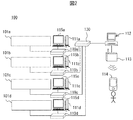
- the configuration of the automatic analysis system 100 including a plurality of automatic analyzers 101a, 101b, 101c, and 101d will be described with reference to FIG.
- the automatic analysis system 100 of FIG. 2 includes a communication device 130, an information management PC 112, a wireless communication device 113, and a mobile terminal 114, and each of the four automatic analysis devices 101a to 101d has a communication device 110a to 110d and an operation unit PC111a. ⁇ 111d, connected to fixed monitor devices 115a ⁇ 115d.
- the information management PC 112 is connected to the automatic analyzers 101a to 101d and the operation units PC111a to 111d via the communication devices 130 and the communication devices 110a to 110d.
- the number of automatic analyzers 101 connected via the communication device 130 is not limited as long as it is one or more, and the configuration, model, and the like may be different when there are a plurality of automatic analyzers 101.
- the information management PC 112 collects information on the communication devices 130 and the automatic analyzers 101a to 101d connected via the communication devices 110a to 110d.
- the mobile terminal 114 wirelessly communicates with the information management PC 112 via the wireless communication device 113, and displays the information acquired from the operation units PC 111a to 111d.
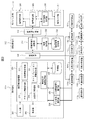
- the functional configurations of the operation units PC 111a to 111d, the information management PC 112, and the mobile terminal 114 included in the automatic analysis system 100 illustrated in FIG. 2 will be described with reference to FIG. Since the operation units PC111a to 111d have the same functional configuration, the operation units PC111a will be illustrated, and the operation units PC111b to 111d will be omitted.
- the operation unit PC111a communicates with the automatic analyzer 101a via the communication device 110a to control the operations of the sample input unit 104, the sample transfer unit 105, the sample analysis unit 106a, 106b, 106c, the sample storage unit 109, and the like.
- the operation unit PC111a includes an input unit 201, a display unit 202, a device information management unit 203, an analysis unit communication unit 204, an information management PC communication unit 205, and a storage unit 206.
- the display unit 202 is, for example, a monitor device or the like.
- the input unit 201 may be, for example, a mouse or a keyboard, and when the display unit 202 is a touch panel, it may be a GUI (Graphical User Interface) displayed on the touch panel.
- GUI Graphic User Interface
- a screen created based on the information or the like input using the input unit 201 is displayed on the display unit 202.
- the device information management unit 203 includes an alarm information management unit 221, a reagent information management unit 222, a measurement end management unit 223, a calibration information management unit 224, a quality control information management unit 225, and the like.
- the alarm information management unit 221 stores the information related to the abnormality in the storage unit 206 in order to notify the display unit 202 and the mobile terminal 114 of the abnormality emitted from the automatic analyzer 101a.
- the reagent information management unit 222 manages information on reagents such as reagent containers 107 stored in reagent disks 108a, 108b, and 108c.
- the information managed by the reagent information management unit 222 includes the reagent corresponding to the analysis item, the remaining amount of the reagent contained in each reagent container 107, and the case where a plurality of reagent containers 107 are installed for one analysis item. Priority of use, reagent expiration date, etc. are included.
- the measurement end management unit 223 monitors whether or not the measurement result of the sample is output from the automatic analyzer 101a, and stores the information related to the end of the measurement of the sample in order to notify the mobile terminal 114 when the measurement result is output. Stored in part 206.
- the measurement result output from the automatic analyzer 101a includes not only the measurement result of the sample provided by the patient but also the measurement result of the standard sample used for calibration and quality control.
- the calibration information management unit 224 manages information related to the calibration executed by the automatic analyzer 101a.
- the information managed by the calibration information management unit 224 includes the standard sample corresponding to the analysis item of the calibration, the information related to the sample rack 103 on which the sample cup 102 to which the standard sample is dispensed is loaded, and the information of the calibration. It includes information on the resulting calibration curve and calibration factors.
- the quality control information management unit 225 manages information related to quality control executed by the automatic analyzer 101a.
- the information managed by the quality control information management unit 225 includes the standard sample corresponding to the analysis item of the quality control, the information related to the sample rack 103 on which the sample cup 102 to which the standard sample is dispensed is loaded, and the information of the quality control. Information related to the result is included.
- the communication unit 204 of the analysis unit controls communication with the automatic analysis device 101a, creates a communication text transmitted to the automatic analysis device 101a, for example, a text requesting an analysis item, and a communication text received from the automatic analysis device 101a. Distribute information.
- the information management PC 112 has an information management PC communication unit 231, an information management unit 232, and an information management storage unit 233.
- the information management PC communication unit 231 controls wireless communication with the mobile terminal 114, creates a communication text transmitted to the mobile terminal 114, and distributes information of the communication text received from the mobile terminal 114 to the operation unit PC 111a. Send information.
- the information management unit 232 stores the identification information of the automatic analyzers 101a to 101d, for example, the IP address, etc. in the information management storage unit 233. Further, the information management unit 232 performs communication such as acquisition of device information to the relevant automatic analyzer through the information management PC communication unit 231 according to the content of the instruction from the mobile terminal 114.
- the mobile terminal 114 has a terminal display unit 208, a terminal communication unit 209, a terminal information management unit 210, a terminal input unit 211, and the like.
- the mobile terminal 114 acquires information from the automatic analyzers 101a to 101d and operates the automatic analyzers 101a to 101d by communicating with the operation units PCs 111a to 111d via the wireless communication device 113 and the information management PC 112. ..
- the terminal communication unit 209 controls communication with the information management PC 112 and the operation units PC 111a to 111d, creates a communication text transmitted to the information management PC 112, distributes information of the communication text received from the information management PC 112, and the like. ..
- the terminal information management unit 210 displays a screen created based on the information received by the terminal communication unit 209 on the terminal display unit 208, or transmits information input to the terminal input unit 211 to the terminal communication unit 209. do.
- the terminal display unit 208 is a touch panel, and the terminal input unit 211 is a GUI displayed on the touch panel.
- the terminal display unit 208 displays a screen related to calibration and quality control, and the displayed screen is switched based on the information input to the terminal input unit 211.
- the screen related to calibration and quality control is, for example, a screen including a request list, a preparation list, and a result list.
- the request list is a list including request information which is information related to the request for calibration or quality control, and will be described later with reference to FIGS. 5A and 5B.
- the preparation list is a list including preparation information which is information related to the preparation of a standard sample used in response to a request for calibration or quality control, and will be described later with reference to FIGS. 6A and 6B.
- the standard sample used for calibration is called a standard solution, and the standard sample used for quality control is called a control.
- the result list is a list including result information which is information related to the result of performing calibration or quality control in response to the request, and will be described later with reference to FIGS. 7A and 7B.
- the information management unit 232, the communication device 130, and the information management PC communication unit 231 shown in FIG. 3 include these as a set outside the information management PC 112 (for example, operation units PC111a, 111b, ..., And so on. It may be provided in the automatic analyzer 101a, 101b, ..., Etc.). In that case, the communication device 130 does not perform data communication, but transfers data inside the device or functional portion provided with the set.
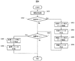
- the information management unit 232 acquires the information of the automatic analyzer 101 according to the content of the instruction from the mobile terminal 114.
- the acquired information may be read from the information management storage unit 233, or may be received from the outside via the information management PC communication unit 231.
- the information management unit 232 determines whether or not the information acquired in S401 includes an item related to a request for calibration or quality control. If the item related to the request is included, the process proceeds to S403, and if it is not included, the process proceeds to S407.
- the information management unit 232 extracts the data for the request list from the information acquired in S401.
- the data for the calibration request list includes the item name of the calibration, the position where the reagent used for calibration is installed, the method of executing the calibration, and even if the usage status of the reagent is further included. good.
- the data for the quality control request list includes the item name of the quality control and the position where the reagent used for the quality control is installed, and may further include the factor of the request.
- the information management unit 232 creates a request list using the data extracted in S403.
- the created request list is displayed on, for example, the terminal display unit 208.
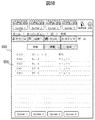
- the calibration request list screen 500 which is an example of the screen including the calibration request list, will be described with reference to FIG. 5A.
- connection device display units 501a to 501d On the calibration request list screen 500, connection device display units 501a to 501d, screen transition tabs 503, list tab 504, calibration request list 505, and device switching buttons 506a to 506d are displayed.
- connection device display units 501a to 501d are buttons corresponding to the automatic analysis devices 101a to 101d included in the automatic analysis system 100, respectively, and indicate which information in the automatic analysis devices 101a to 101d is displayed.
- the display of the information of System1 in the four automatic analyzers 101a to 101d is indicated by a downward triangle arranged below the connection device display units 501a to 501d.
- At least one automatic analyzer 101 may be displayed on the connection device display unit 501, and the number is not limited.
- FIG. 5A exemplifies an alarm notification icon 511, a reagent remaining amount shortage notification icon 512, a standard sample measurement end notification icon 513, and an emergency sample measurement end notification icon 514.
- the display of the alarm notification icon 511, the reagent remaining amount shortage notification icon 512, the standard sample measurement end notification icon 513, and the emergency sample measurement end notification icon 514 is controlled by the terminal information management unit 210.
- the alarm notification icon 511 is an icon indicating that an abnormality has occurred in the automatic analyzer 101, and blinks or discolors according to the content notified from the alarm information management unit 221. For example, when there are two levels of abnormality, "Caution” and "Stop”, the alarm notification icon 511 turns yellow at the "Caution” level and blinks red at the "Stop” level. When a plurality of abnormalities are notified to the mobile terminal 114, the alarm notification icon 511 blinks according to the content having the highest abnormality level.
- the reagent remaining amount shortage notification icon 512 is an icon indicating that the remaining amount of the reagent contained in the reagent container 107 has become insufficient, and blinks or blinks according to the content notified from the reagent information management unit 222. It discolors. For example, when the level of insufficient remaining amount is three stages of "preparation”, “insufficient”, and “warning", the reagent remaining amount insufficient notification icon 512 changes color and blinks according to the stage. When the mobile terminal 114 is notified that the remaining amount of a plurality of reagents is insufficient, the reagent remaining amount notification icon 512 corresponding to the most urgent reagent blinks.
- the standard sample measurement end notification icon 513 is an icon indicating that the measurement related to calibration or quality control has been completed, and blinks according to the content notified from the calibration information management unit 224 or the quality control information management unit 225. Or discolor. For example, when the content notified from the calibration information management unit 224 has two stages of “success” and “failure", the standard sample measurement end notification icon 513 is blue when “success” and red when “failure”. Flashes with. When calibration of multiple analysis items is executed and "success" and "failure" are notified to the mobile terminal 114 at the same time, the notification content of "failure" is prioritized and the corresponding standard sample measurement end notification icon 513 blinks.
- the standard sample measurement end notification icon 513 is blue when it is “within the control range”. Flashes in red when "out of control”.
- the notification icon 513 flashes.
- the standard sample measurement end notification icon 513 may be divided into those for calibration and those for quality control.
- the two stages of "success” and “failure” or "within the control range” and “out of the control range” may be set to three or more levels.
- the emergency sample measurement end notification icon 514 is an icon indicating that the measurement of the emergency sample has been completed, and blinks or discolors according to the content notified from the measurement end management unit 223. Whether or not the measured sample is an emergency sample can be identified by a barcode attached to the sample rack 103 on which the sample cup 102 is loaded. That is, when the sample of the sample cup 102 loaded on the sample rack 103 to which the bar code for the emergency sample is attached is measured, the bar code is read and it is recognized that the sample is an emergency sample. When the mobile terminal 114 is notified that the measurement of the emergency sample is completed, the emergency sample measurement end notification icon 514 blinks. When the mobile terminal 114 is notified that the remaining amount of a plurality of reagents is insufficient, the reagent remaining amount notification icon 512 corresponding to the most urgent reagent blinks.
- the device switching buttons 506a to 506d are buttons for switching which information in the automatic analysis devices 101a to 101d included in the automatic analysis system 100 is to be displayed on the calibration request list screen 500. For example, if the device switching button 506b is pressed while displaying the information of System1, the information displayed on the calibration request list screen 500 is switched to the information of System2.
- the screen transition tab 503 is a tab for switching the screen displayed on the terminal display unit 208.
- the screen transition tab 503 includes, for example, an alarm tab for displaying alarm information, a reagent tab for displaying the usage status of reagents such as the remaining amount of reagent, a rack tab for displaying the status of measured samples, and a caliber tab for displaying calibration information.
- a QC tab that displays quality control information. For example, if the caliber tab is pressed while the alarm information is being displayed, the calibration information is displayed. When the caliber tab or QC tab is pressed, the list tab 504 is displayed. Further, the calib / QC tab in which the calib tab and the QC tab are integrated may be displayed.
- the list tab 504 is a tab for switching the list displayed on the terminal display unit 208.
- the list tab 504 includes, for example, a request tab for displaying a request list, a preparation tab for displaying a preparation list, and a result tab for displaying a result list. For example, if the preparation tab is pressed while the request tab of the caliber tab is displayed, the preparation list is displayed.
- the calibration request list 505 at least the item name of the calibration, the position where the reagent used for the calibration is installed, and the method of executing the calibration are displayed.
- the operator can confirm the content of the calibration request.
- the calibration request list 505 may display the usage status of the reagent.
- the operator can confirm the usage status of the reagent used for calibration.
- the reagents may be sorted at the position where the reagents are installed.
- the operator can confirm the request contents according to the arrangement of positions, so that the confirmation time can be shortened.
- the quality control request list screen 550 which is an example of the screen including the quality control request list, will be described with reference to FIG. 5B. Similar to the calibration request list screen 500, the quality control request list screen 550 displays the connection device display units 501a to 501d, the screen transition tab 503, the list tab 504, and the device switching buttons 506a to 506d, and also performs quality control.
- the request list 555 is displayed. Except for the quality control request list 555, the description is the same as in FIG. 5A, so the description thereof will be omitted.
- the quality control request list 555 at least the item name of the quality control and the position where the reagent used for the quality control is installed are displayed. By displaying the item name and position, the operator can confirm the content of the request for quality control. Further, the factor of the request may be displayed in the quality control request list 555. By displaying the cause of the request, the operator can confirm on what basis the quality control was requested. For example, if "manual" is displayed in the factor column, it can be confirmed that the quality control is requested by the operator. In addition, if the items displayed as "manual" do not include the analysis items that the operator was planning to request, the omission of the request can be noticed.
- a screen including a calibration / accuracy control request list that integrates the calibration request list 505 and the quality control request list 555 may be displayed on the terminal display unit 208.
- the calibration request items displayed in the calibration request list 505 may be displayed in the quality control request list 555.
- the information management unit 232 extracts the data for the preparation list from the information acquired in S401.
- the data for the calibration preparation list includes the rack number, which is the number assigned to the rack in which the standard solution used for calibration is installed, and each position in the rack in which the standard solution is installed.
- the rack position number and the name of the standard solution are included, and the code of the standard solution and the lot number may be further included.
- the data for the quality control preparation list includes the rack number, which is the number assigned to the rack in which the control used for quality control is installed, and the number assigned to each position in the rack in which the control is installed.
- the in-rack position number which is, the name of the control, and the code of the control and the lot number may be further included.
- the information management unit 232 creates a preparation list using the data extracted in S405.
- the created preparation list is displayed on, for example, the terminal display unit 208.
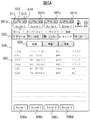
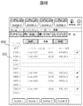
- the calibration preparation list screen 600 which is an example of the screen including the calibration preparation list, will be described with reference to FIG. 6A. Similar to the calibration request list screen 500, the calibration preparation list screen 600 displays the connection device display units 501a to 501d, the screen transition tab 503, the list tab 504, and the device switching buttons 506a to 506d, and also performs calibration.
- the preparation list 605 is displayed. Except for the calibration preparation list 605, the description is the same as in FIG. 5A, and the description thereof will be omitted.
- the calibration preparation list 605 is a rack indicating at least the position (which position in the rack) in which the standard solution used for calibration is installed for all the analysis items displayed in the calibration request list 505.
- the inner position number and the name of the standard solution are displayed in association with each other.
- the position number in the rack may be configured as a combination of, for example, a rack number (30001 or the like) and a number indicating a standard liquid arrangement position in the rack (1 to 5 or the like).
- the line of the position number in the rack where the standard liquid is not installed because it was not set in the device is displayed as a blank, and the line of the position number in the rack where the standard liquid is installed is displayed with the name of the corresponding standard liquid.
- NS the line of the position number in the rack where the standard liquid is installed because it was not set in the device.
- FIG. 6A it is shown that no standard solution is installed at position numbers 30001-3 to 30001-5, 30002-4, and 30003-1 in the rack. From such a display, the operator can determine whether or not the sample cup 102 is loaded in the sample rack 103, and misplacement of the standard liquid can be suppressed.
- the standard solution code and lot number may be displayed on the calibration preparation list 605. By displaying the standard solution code and lot number, the standard solution can be uniquely determined. Further, a check box may be displayed in the calibration preparation list 605. The check box may be used, for example, to prevent forgetting to take out the standard solution, and is checked when the standard solution is taken out from the refrigerator in which the standard solution is stored. It should be noted that the sorting by the standard liquid name may be performed by pressing the sort button displayed in the standard liquid name column and having an upward triangular shape. By sorting by the standard liquid name, the operator can confirm the request contents according to the order of the standard liquid names, so that the confirmation time can be shortened.
- the quality control preparation list screen 650 which is an example of the screen including the quality control preparation list, will be described with reference to FIG. 6B. Similar to the calibration request list screen 500, the quality control preparation list screen 650 displays the connection device display units 501a to 501d, the screen transition tab 503, the list tab 504, and the device switching buttons 506a to 506d, and also performs quality control.
- the preparation list 655 is displayed. Except for the quality control preparation list 655, the description is the same as in FIG. 5A, and the description thereof will be omitted.
- the quality control preparation list 655 shows at least the position (which position in the rack) in which the control used for quality control is installed for all the analysis items displayed in the quality control request list 555.
- the position number and the control name are displayed in association with each other.
- the position number in the rack may be configured as a combination of, for example, a rack number (20001 or the like) and a number indicating a control arrangement position in the rack (1 to 5 or the like).
- the line of the position number in the rack where the control is not installed because it was not set in the device is displayed as a blank, and the name of the corresponding control is displayed in the line of the position number in the rack where the control is installed.
- FIG. 6B it is shown that no controls are installed at position numbers 20001-3 to 20001-5, 20002-4, and 20003-1 in the rack. With such a display, the operator can determine whether or not the sample cup 102 is loaded in the sample rack 103, and misplacement of the control can be suppressed.
- control code and lot number may be displayed on the quality control preparation list 655.
- the control can be uniquely determined by displaying the control code and lot number.
- a check box may be displayed in the quality control preparation list 655.
- a screen including a calibration / accuracy control preparation list that integrates the calibration preparation list 605 and the quality control preparation list 655 may be displayed on the terminal display unit 208.
- the information management unit 232 determines whether or not the information acquired in S401 includes the result information of calibration or quality control. If the result information is included, the process proceeds to S408, and if it is not included, the process flow ends.
- the information management unit 232 extracts the data for the result list from the information acquired in S401.
- the data for the calibration result list includes the item name of the calibration, the position where the reagent used for the calibration is installed, the result of the calibration, the usage status of the reagent, and the standard solution. Name, code, lot number may be further included.
- the data for the quality control result list includes the quality control item name, the position where the reagents used for quality control are installed, the result of the quality control execution, and the control name, code, and lot number. May be further included.
- the information management unit 232 creates a result list using the data extracted in S408.
- the created result list is displayed on, for example, the terminal display unit 208.
- the calibration result list screen 700 which is an example of the screen including the calibration result list, will be described with reference to FIG. 7A. Similar to the calibration request list screen 500, the calibration result list screen 700 displays the connection device display units 501a to 501d, the screen transition tab 503, the list tab 504, and the device switching buttons 506a to 506d, and also performs calibration. The result list 705 is displayed. Except for the calibration result list 705, the description is the same as in FIG. 5A, and the description thereof will be omitted.
- the calibration result list 705 at least the item name of the calibration, the position where the reagent used for the calibration is installed, and the result of the calibration are displayed.
- the calibration for example, "success" or "failure” which is the content notified from the calibration information management unit 224 is displayed.
- the operator can grasp the result of the calibration executed in response to the request. Instead of displaying "failure", the cause of failure, for example, "insufficient reagent" may be displayed.
- the name, code, and lot number of the standard solution may be displayed in the calibration result list 705.
- the calibration result list 705 may display a ">" link for calling up the detailed result. By pressing the ">" link, a screen for displaying the detailed calibration result is called. The screen for displaying the detailed calibration result will be described later with reference to FIGS. 8A, 8B, and 9.
- the quality control result list screen 750 which is an example of the screen including the quality control result list, will be described with reference to FIG. 7B. Similar to the calibration request list screen 500, the quality control result list screen 750 displays the connection device display units 501a to 501d, the screen transition tab 503, the list tab 504, and the device switching buttons 506a to 506d, and also performs quality control.
- the result list 755 is displayed. Except for the quality control result list 755, the description is the same as in FIG. 5A, and the description thereof will be omitted.
- the quality control result list 755 At least the item name of the quality control, the position where the reagent used for the quality control is installed, and the result of the quality control being executed are displayed. As a result of the calibration being executed, for example, "within the control range” or "out of the control range", which is the content notified from the quality control information management unit 225, is displayed. By displaying the item name, position, and execution result, the operator can grasp the result of the quality control executed in response to the request.
- control name, code, and lot number may be displayed in the quality control result list 755.
- the control can be uniquely determined by displaying the control code and lot number.
- a ">" link for calling the detailed result may be displayed in the quality control result list 755. The screen for displaying the detailed result of the quality control will be described later with reference to FIGS. 10A and 10B.
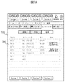
- the colorimetric calibration detailed result screen 800 which is an example of the screen including the detailed calibration result, will be described with reference to FIG. 8A.
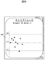
- the colorimetric caliber trace button 801 is a button for displaying the caliber trace graph 806 exemplified in FIG. 8B.
- the vertical axis is the measured value and the horizontal axis is the number of measurements.
- the measured value on the vertical axis of the caliber trace graph 806 has a different unit for each item.
- the caliber trace graph 806 may be displayed so that the operator can confirm it regardless of whether the mobile terminal 114 is in landscape orientation or portrait orientation.
- the calibration curve button 802 is a button for displaying a calibration curve graph in which the vertical axis is the absorbance and the horizontal axis is the concentration of a specific component contained in the sample.
- the colorimetric caliber factor 803 is a coefficient calculated from the absorbance obtained by measuring a standard solution for calibration. The coefficients include S1Abs, K, A, B, C, L, H, I, and these coefficients are used to prepare the calibration curve. L is a coefficient indicating the degree of turbidity of serum, H is a coefficient indicating the degree of hemolysis of serum, and I is a coefficient indicating the degree of yellowness of serum.
- the display of the colorimetric caliber factor 803 is indispensable.
- Reagent information 804 for colorimetry is information related to reagents used for measuring colorimetric items, and positions, lots, and sequences are associated with each reagent number R1 or R3. It is preferable that the reagent information 804 for colorimetry is displayed.
- the standard liquid information 805 for colorimetry is information related to the standard liquid used for measuring the colorimetric item, and the rack number, the position number in the rack, the code, and the lot are associated with each standard liquid name.
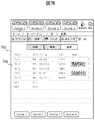
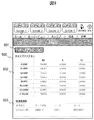
- the electrolyte calibration detailed result screen 900 which is an example of the screen including the detailed calibration result, will be described with reference to FIG.
- the electrolyte calib trace button 901 the electrolyte caliber factor 902, and the electrolyte standard liquid information 903 are displayed.
- the electrolyte caliber trace button 901 is a button for displaying a caliber trace graph in which the vertical axis represents the measured value and the horizontal axis represents the number of measurements.
- the electrolyte caliber factor 902 is a coefficient used for creating a calibration curve for ISE (Ion Selective Electrode), and is an IS. EMF, S1. EMF, S2. EMF, S3. EMF, SLOPE, IS. CONC, S3. CONC, C.I. VALUE is included.
- IS. EMF is the internal electromotive force, S1. EMF is the electromotive force of a low-concentration standard solution, S2. EMF is the electromotive force of a high-concentration standard solution, S3. EMF is the electromotive force of an intermediate concentration standard solution.
- SLOPE is the slope value
- IS. CONC is the concentration of the internal standard solution
- S3. CONC is the measured concentration of the intermediate concentration standard solution, C.I.
- the VALUE is a correction factor. Labeling of the electrolyte caliber factor 902 is mandatory.
- the electrolyte standard solution information 903 is information related to the standard solution used for measuring the electrolyte item, and the rack number, the position number in the rack, the code, and the lot are associated with each standard solution name.
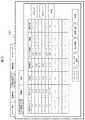
- the accuracy control detailed result screen 1000 which is an example of the screen including the detailed result of the quality control, will be described with reference to FIG. 10A.
- the daily chart button 1001 On the quality control detailed result screen 1000, the daily chart button 1001, the daily difference chart button 1002, the measured value 1003, the reagent information 1004, and the control information 1005 are displayed.
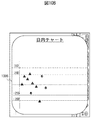
- the diurnal chart button 1001 is a button for displaying the diurnal chart 1006 illustrated in FIG. 10B.
- the daily chart 1006 is a graph in which the vertical axis represents the measured value with respect to the control range and the horizontal axis represents the number of measurements, and is used for confirming the transition of the measured value within the day.
- the measured value for the control range which is the vertical axis of the daily chart 1006, is displayed as a value for the standard deviation SD (Standard Deviation) of the control range when the average value of the control range is set to 0.
- the daily difference chart button 1002 is a button for displaying the daily difference chart in which the daily difference chart 1006 is accumulated day by day and the daily difference data is graphed.
- the daily chart 1006 and the daily difference chart may be displayed so that the operator can confirm them regardless of whether the mobile terminal 114 is in landscape orientation or portrait orientation.
- the measured value 1003 is data related to the result of executing the quality control, and includes the measurement result, the upper limit value, the lower limit value, and the control SD.
- the measurement result is a measured value measured by executing quality control, and it is confirmed that it is within the control range defined by the upper limit value and the lower limit value.
- the management SD is the standard deviation of the permissible variation of the control.
- the display of the measured value 1003 is indispensable.
- Reagent information 1004 is information related to reagents used for quality control, and positions, lots, and sequences are associated with each reagent number R1 or R3. Reagent information 1004 is preferably displayed.
- the control information 1005 is information related to the control used for quality control, and the rack number, the position number in the rack, the code, and the lot are associated with each control name.
- At least one of a request list, a preparation list, and a result list including information related to calibration or quality control is displayed on the mobile terminal 114.
- the display of information related to calibration or quality control is not limited to the mobile terminal 114, and may be a fixed monitor device 115.
- An example of a screen displayed on the fixed monitor device 115 will be described with reference to FIGS. 11 to 13.
- FIG. 11 is an example of the routine operation monitor screen 1101 in which the information necessary for the routine work performed by the operator is displayed.
- the routine operation monitor screen 1101 the standard solution required for each analysis item is displayed. That is, although the routine operation monitor screen 1101 is suitable for checking each analysis item, all analysis items must be checked in order to check the standard solution required for each analyzer.
- the calibration preparation list screen 600 shown in FIG. 6A the standard liquids required for each analyzer are collectively displayed, so that the time required for confirming the calibration preparation can be shortened.
- FIG. 12 is an example of the calibration monitor screen 1201 that displays general information related to calibration.
- the calibration monitor screen 1201 is suitable for confirming general information related to calibration, for example, in order to confirm an item requested by an operator, the operator must extract the corresponding item.
- the quality control request list screen 550 illustrated in FIG. 5B only the items requested by the operator are displayed, so that the time required for confirming the quality control request can be shortened.
- FIG. 13 is an example of the calibration result monitor screen 1301 that displays the result of the calibration of the analysis items displayed on the calibration monitor screen 1201.
- the calibration result monitor screen 1301 is suitable for confirming all the results of performing the calibration, for example, in order to analyze the factors when the calibration fails, the displayed information must be reviewed.
- the reagent information 804 for color matching and the standard solution information 805 for color matching are displayed on the colorimetric calibration detailed result screen 800 shown in FIG. 8A, the reagent and the standard solution are the causes of failure. You can quickly determine whether or not it is.
- 100 Automatic analysis system
- 101 Automatic analyzer
- 102 Specimen cup
- 103 Specimen rack
- 104 Specimen loading unit
- 105 Specimen transport unit
- 106 Specimen analysis unit
- 107 Reagent container
- 108 Reagent disk
- 109 Specimen storage unit
- 110 Communication device
- 111 Operation unit PC
- 112 Information management PC
- 113 Wireless communication device
- 114 Mobile terminal
- 115 Fixed monitor device
- 120 Reaction disk
- 121 Sample dispensing Unit
- 122 Reagent dispensing unit
- 123 Photometric unit
- 130 Communication equipment
- 201 Input unit
- 202 Display unit
- 203 Equipment information management unit
- 204 Analysis unit communication unit
- 205 Information management PC Communication unit
- 206 Storage unit
- 208 Terminal display unit
- 209 Terminal communication unit
- 210 Terminal information management unit
- 211 Terminal input unit
- 221 Alarm information management unit
- 222 Reagent information management unit
Landscapes
- Chemical & Material Sciences (AREA)
- Biochemistry (AREA)
- Physics & Mathematics (AREA)
- Health & Medical Sciences (AREA)
- Life Sciences & Earth Sciences (AREA)
- Analytical Chemistry (AREA)
- General Health & Medical Sciences (AREA)
- General Physics & Mathematics (AREA)
- Immunology (AREA)
- Pathology (AREA)
- Engineering & Computer Science (AREA)
- Quality & Reliability (AREA)
- Chemical Kinetics & Catalysis (AREA)
- Automatic Analysis And Handling Materials Therefor (AREA)
Priority Applications (4)
| Application Number | Priority Date | Filing Date | Title |
|---|---|---|---|
| JP2022509309A JP7386321B2 (ja) | 2020-03-23 | 2021-01-18 | 自動分析システム |
| CN202180020871.8A CN115298550A (zh) | 2020-03-23 | 2021-01-18 | 自动分析系统 |
| US17/911,162 US20230107051A1 (en) | 2020-03-23 | 2021-01-18 | Automatic Analysis System |
| EP21775637.8A EP4130748A4 (en) | 2020-03-23 | 2021-01-18 | AUTOMATIC ANALYSIS SYSTEM |
Applications Claiming Priority (2)
| Application Number | Priority Date | Filing Date | Title |
|---|---|---|---|
| JP2020-050598 | 2020-03-23 | ||
| JP2020050598 | 2020-03-23 |
Publications (1)
| Publication Number | Publication Date |
|---|---|
| WO2021192537A1 true WO2021192537A1 (ja) | 2021-09-30 |
Family
ID=77891367
Family Applications (1)
| Application Number | Title | Priority Date | Filing Date |
|---|---|---|---|
| PCT/JP2021/001437 Ceased WO2021192537A1 (ja) | 2020-03-23 | 2021-01-18 | 自動分析システム |
Country Status (5)
| Country | Link |
|---|---|
| US (1) | US20230107051A1 (enExample) |
| EP (1) | EP4130748A4 (enExample) |
| JP (1) | JP7386321B2 (enExample) |
| CN (1) | CN115298550A (enExample) |
| WO (1) | WO2021192537A1 (enExample) |
Cited By (2)
| Publication number | Priority date | Publication date | Assignee | Title |
|---|---|---|---|---|
| CN114579018A (zh) * | 2022-03-04 | 2022-06-03 | 中元汇吉生物技术股份有限公司 | 图形化显示装置、方法、设备及计算机可读存储介质 |
| WO2025225236A1 (ja) * | 2024-04-24 | 2025-10-30 | 株式会社日立ハイテク | 電解質分析装置、及び電解質分析装置の結果表示方法 |
Families Citing this family (3)
| Publication number | Priority date | Publication date | Assignee | Title |
|---|---|---|---|---|
| CN117741170B (zh) * | 2024-02-19 | 2024-05-24 | 深圳市帝迈生物技术有限公司 | 质控品实验项目登记方法及检测控制方法 |
| CN117783564B (zh) * | 2024-02-19 | 2024-05-28 | 深圳市帝迈生物技术有限公司 | 通道设置方法及样本实验项目登记方法 |
| CN117783565B (zh) * | 2024-02-19 | 2024-05-24 | 深圳市帝迈生物技术有限公司 | 通道设置方法及样本实验项目登记方法 |
Citations (4)
| Publication number | Priority date | Publication date | Assignee | Title |
|---|---|---|---|---|
| JP2007078375A (ja) * | 2005-09-12 | 2007-03-29 | Hitachi High-Technologies Corp | 自動分析装置 |
| JP2010151707A (ja) * | 2008-12-26 | 2010-07-08 | Hitachi High-Technologies Corp | 自動分析装置、その支援システム |
| JP2018080957A (ja) * | 2016-11-15 | 2018-05-24 | 日本電子株式会社 | 自動分析装置及びプログラム |
| WO2018168432A1 (ja) * | 2017-03-14 | 2018-09-20 | 株式会社日立ハイテクノロジーズ | 自動分析システム |
Family Cites Families (6)
| Publication number | Priority date | Publication date | Assignee | Title |
|---|---|---|---|---|
| DE69837230T2 (de) * | 1997-04-10 | 2007-12-20 | Hitachi, Ltd. | Automatische Analysevorrichtung |
| JP5191664B2 (ja) | 2007-01-09 | 2013-05-08 | ベックマン コールター, インコーポレイテッド | 分析装置 |
| JP5501205B2 (ja) * | 2010-12-09 | 2014-05-21 | 株式会社日立ハイテクノロジーズ | 自動分析システム |
| US20140252079A1 (en) * | 2013-03-11 | 2014-09-11 | Promega Corporation | Analyzer with machine readable protocol prompting |
| JP6496828B2 (ja) | 2015-08-27 | 2019-04-10 | 株式会社日立ハイテクノロジーズ | 自動分析装置 |
| EP3553530B1 (en) * | 2018-04-10 | 2023-09-20 | Jeol Ltd. | Automatic analyzer and program |
-
2021
- 2021-01-18 US US17/911,162 patent/US20230107051A1/en active Pending
- 2021-01-18 EP EP21775637.8A patent/EP4130748A4/en active Pending
- 2021-01-18 JP JP2022509309A patent/JP7386321B2/ja active Active
- 2021-01-18 CN CN202180020871.8A patent/CN115298550A/zh active Pending
- 2021-01-18 WO PCT/JP2021/001437 patent/WO2021192537A1/ja not_active Ceased
Patent Citations (4)
| Publication number | Priority date | Publication date | Assignee | Title |
|---|---|---|---|---|
| JP2007078375A (ja) * | 2005-09-12 | 2007-03-29 | Hitachi High-Technologies Corp | 自動分析装置 |
| JP2010151707A (ja) * | 2008-12-26 | 2010-07-08 | Hitachi High-Technologies Corp | 自動分析装置、その支援システム |
| JP2018080957A (ja) * | 2016-11-15 | 2018-05-24 | 日本電子株式会社 | 自動分析装置及びプログラム |
| WO2018168432A1 (ja) * | 2017-03-14 | 2018-09-20 | 株式会社日立ハイテクノロジーズ | 自動分析システム |
Non-Patent Citations (1)
| Title |
|---|
| See also references of EP4130748A4 * |
Cited By (2)
| Publication number | Priority date | Publication date | Assignee | Title |
|---|---|---|---|---|
| CN114579018A (zh) * | 2022-03-04 | 2022-06-03 | 中元汇吉生物技术股份有限公司 | 图形化显示装置、方法、设备及计算机可读存储介质 |
| WO2025225236A1 (ja) * | 2024-04-24 | 2025-10-30 | 株式会社日立ハイテク | 電解質分析装置、及び電解質分析装置の結果表示方法 |
Also Published As
| Publication number | Publication date |
|---|---|
| JPWO2021192537A1 (enExample) | 2021-09-30 |
| EP4130748A1 (en) | 2023-02-08 |
| US20230107051A1 (en) | 2023-04-06 |
| EP4130748A4 (en) | 2024-03-27 |
| CN115298550A (zh) | 2022-11-04 |
| JP7386321B2 (ja) | 2023-11-24 |
Similar Documents
| Publication | Publication Date | Title |
|---|---|---|
| WO2021192537A1 (ja) | 自動分析システム | |
| US8524153B2 (en) | Quality control system | |
| JP4558017B2 (ja) | 自動分析装置および自動分析装置の使用方法 | |
| JP4832121B2 (ja) | 分析システム | |
| US20180128741A1 (en) | Automatic analyzer | |
| US6984527B2 (en) | Automated quality control protocols in a multi-analyzer system | |
| EP2068153B1 (en) | Automatic analyzer | |
| CN101498735B (zh) | 自动分析装置 | |
| US20080219887A1 (en) | Automatic analyzer | |
| EP3422015B1 (en) | Automated analysis device | |
| JP7219760B2 (ja) | 自動分析装置 | |
| WO2013065528A1 (ja) | 自動分析システム | |
| CN101393227B (zh) | 标本分析仪及标本分析方法 | |
| JP2011191204A (ja) | 臨床検査装置、臨床検査情報管理システム、及びコンピュータプログラム | |
| WO2018168431A1 (ja) | 自動分析システム | |
| US20220034923A1 (en) | Automatic analyzer | |
| CN109387648B (zh) | 自动分析系统 | |
| JP2012032188A (ja) | 自動分析システム | |
| JP2005274469A (ja) | 分析装置 | |
| CN114910655A (zh) | 样本检验系统、样本分析仪、样本分析仪管理系统及方法 | |
| JPH11108938A (ja) | 自動分析装置 | |
| US20250224412A1 (en) | Automatic analysis system and mobile terminal | |
| Sunheimer et al. | 5 ANALYSIS: CLINICAL LABORATORY |
Legal Events
| Date | Code | Title | Description |
|---|---|---|---|
| 121 | Ep: the epo has been informed by wipo that ep was designated in this application |
Ref document number: 21775637 Country of ref document: EP Kind code of ref document: A1 |
|
| ENP | Entry into the national phase |
Ref document number: 2022509309 Country of ref document: JP Kind code of ref document: A |
|
| NENP | Non-entry into the national phase |
Ref country code: DE |
|
| ENP | Entry into the national phase |
Ref document number: 2021775637 Country of ref document: EP Effective date: 20221024 |