WO2021192531A1 - 回転電機の固定子の製造方法、回転電機の固定子、及び回転電機 - Google Patents
回転電機の固定子の製造方法、回転電機の固定子、及び回転電機 Download PDFInfo
- Publication number
- WO2021192531A1 WO2021192531A1 PCT/JP2021/001187 JP2021001187W WO2021192531A1 WO 2021192531 A1 WO2021192531 A1 WO 2021192531A1 JP 2021001187 W JP2021001187 W JP 2021001187W WO 2021192531 A1 WO2021192531 A1 WO 2021192531A1
- Authority
- WO
- WIPO (PCT)
- Prior art keywords
- varnish
- stator
- coil
- electric machine
- rotary electric
- Prior art date
- Legal status (The legal status is an assumption and is not a legal conclusion. Google has not performed a legal analysis and makes no representation as to the accuracy of the status listed.)
- Ceased
Links
Images


Classifications
-
- H—ELECTRICITY
- H02—GENERATION; CONVERSION OR DISTRIBUTION OF ELECTRIC POWER
- H02K—DYNAMO-ELECTRIC MACHINES
- H02K15/00—Processes or apparatus specially adapted for manufacturing, assembling, maintaining or repairing of dynamo-electric machines
- H02K15/12—Impregnating, moulding insulation, heating or drying of windings, stators, rotors or machines
-
- H—ELECTRICITY
- H02—GENERATION; CONVERSION OR DISTRIBUTION OF ELECTRIC POWER
- H02K—DYNAMO-ELECTRIC MACHINES
- H02K1/00—Details of the magnetic circuit
- H02K1/06—Details of the magnetic circuit characterised by the shape, form or construction
- H02K1/12—Stationary parts of the magnetic circuit
- H02K1/16—Stator cores with slots for windings
-
- H—ELECTRICITY
- H02—GENERATION; CONVERSION OR DISTRIBUTION OF ELECTRIC POWER
- H02K—DYNAMO-ELECTRIC MACHINES
- H02K3/00—Details of windings
- H02K3/30—Windings characterised by the insulating material
-
- H—ELECTRICITY
- H02—GENERATION; CONVERSION OR DISTRIBUTION OF ELECTRIC POWER
- H02K—DYNAMO-ELECTRIC MACHINES
- H02K3/00—Details of windings
- H02K3/32—Windings characterised by the shape, form or construction of the insulation
- H02K3/34—Windings characterised by the shape, form or construction of the insulation between conductors or between conductor and core, e.g. slot insulation
- H02K3/345—Windings characterised by the shape, form or construction of the insulation between conductors or between conductor and core, e.g. slot insulation between conductor and core, e.g. slot insulation
-
- H—ELECTRICITY
- H02—GENERATION; CONVERSION OR DISTRIBUTION OF ELECTRIC POWER
- H02K—DYNAMO-ELECTRIC MACHINES
- H02K3/00—Details of windings
- H02K3/46—Fastening of windings on the stator or rotor structure
- H02K3/50—Fastening of winding heads, equalising connectors, or connections thereto
-
- Y—GENERAL TAGGING OF NEW TECHNOLOGICAL DEVELOPMENTS; GENERAL TAGGING OF CROSS-SECTIONAL TECHNOLOGIES SPANNING OVER SEVERAL SECTIONS OF THE IPC; TECHNICAL SUBJECTS COVERED BY FORMER USPC CROSS-REFERENCE ART COLLECTIONS [XRACs] AND DIGESTS
- Y02—TECHNOLOGIES OR APPLICATIONS FOR MITIGATION OR ADAPTATION AGAINST CLIMATE CHANGE
- Y02T—CLIMATE CHANGE MITIGATION TECHNOLOGIES RELATED TO TRANSPORTATION
- Y02T10/00—Road transport of goods or passengers
- Y02T10/60—Other road transportation technologies with climate change mitigation effect
- Y02T10/64—Electric machine technologies in electromobility
Definitions
- the present invention relates to a method for manufacturing a stator of a rotary electric machine.
- stator that houses the coil in the slot formed in the circumferential direction.
- the coil housed in the slot is fixed by a varnish.
- Patent Document 1 Japanese Patent Application Laid-Open No. 2008-109732
- the stator core is held in a posture in which the coil end of the coil mounted on the stator core is up and down, and the coil is held.
- the varnish is injected from the upper surface of the upper coil end protruding from the upper end surface of the stator core, and the varnish impregnating and flowing down from the upper side of the upper coil end protrudes from the lower end surface of the stator core of the coil.
- the varnish is impregnated to the vicinity of the position where gelation started in the first supply step, and then gelation occurs.
- a varnish treatment method is described, which comprises a second supply step of supplying the varnish by controlling the supply amount so as to start (see, for example, claim 1).
- a typical example of the invention disclosed in the present application is as follows. That is, it is a method of manufacturing a stator of a rotary electric machine in which a coil is wound around a stator core, and the coil is arranged on the outermost outer circumference or the innermost outer circumference of a coil end portion in which the coil protrudes from the stator core.
- a second varnish step of forming the second varnish portion is provided so as to provide a non-existing region where the varnish is not applied between the first varnish portion and the second varnish portion.
- FIG. 5 is a cross-sectional view taken along the line AA of the rotary electric machine shown in FIG. It is a perspective view of a stator. It is a schematic diagram of the segment of the stator coil shown in FIG. It is a figure which shows the varnish process. It is a perspective view of the stator coated with varnish. It is a perspective view of the stator coated with varnish. It is the figure which looked at the coil end of the stator coated with varnish from the side.
- the rotary electric machine of this embodiment uses a flat wire capable of miniaturization and high output, it is a rotary electric machine suitable for use in traveling an automobile.
- Vehicles that use a rotary electric machine include a hybrid type electric vehicle (HEV) that has both an engine and a rotary electric machine, and an electric vehicle (EV) that runs only on the rotary electric machine without using an engine.
- HEV hybrid type electric vehicle
- EV electric vehicle
- the rotary electric machine described can be applied to any type. In the following, a rotary electric machine used in a hybrid type automobile will be described as an example.
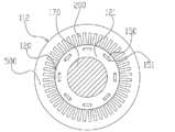
- FIG. 1 is a cross-sectional view of a rotary electric machine 100 according to an embodiment of the present invention.
- the rotary electric machine 100 is a three-phase electric motor with a built-in permanent magnet.
- the rotary electric machine 100 operates as an electric machine in which the stator 120 rotates when the stator coil 110 is wound around the stator core (stator core) 111 and a three-phase AC current is supplied to the stator coil 110.
- the rotary electric machine 100 When the rotary electric machine 100 is driven by the engine, it operates as a generator that generates three-phase alternating current. That is, the above functions can be selectively used depending on the traveling state of the automobile.
- the rotary electric machine 100 has a housing 130 and a stator 112 fixed to the housing 130.
- the stator 112 has a stator coil 110 and a stator core 111 as described above.
- a rotor 120 is rotatably arranged via a gap 140.
- the rotor 120 includes a rotor core 121, a permanent magnet 150, and a non-magnetic backing plate 160.
- the rotor core 121 is fixed to a columnar shaft 170.
- the axial direction of the shaft 170 is referred to as “axial direction”
- the direction of rotation around the axial center is referred to as “circumferential direction”
- the radial direction centered on the axial center is referred to as “diameter direction”.
- the housing 130 has an end bracket 180 provided with bearings 10A and 10B, and the shaft 170 is rotatably held by these bearings 10A and 10B.
- the shaft 170 is provided with a resolver 190 that detects the position of the pole of the rotor 120 and the rotation speed.
- FIG. 2 is a cross-sectional view taken along the line AA of the rotary electric machine 100 shown in FIG.
- the description of the housing 130 and the stator coil 110 is omitted.
- a plurality of slots 200 extending in the axial direction are arranged at equal intervals in the circumferential direction.
- the number of slots 200 is, for example, 48 in this embodiment.
- the stator coil 110 is housed in the slot 200.
- insulating paper (so-called slot liner) is arranged in each slot 200.
- the insulating paper is arranged between the stator coils 110 inserted into the slot 200 and between the stator coil 110 and the inner surface of the slot 200, and is arranged between the stator coils 110 or between the stator coil 110 and the slot 200.
- the insulation withstand voltage between the inner surface and the inner surface is improved.
- the insulating paper is, for example, an insulating sheet of heat-resistant polyamide paper, and has a thickness of about 0.1 to 0.5 mm.
- rectangular parallelepiped magnet insertion holes are arranged at equal intervals in the circumferential direction in the vicinity of the outer peripheral portion.
- Permanent magnets 150 are embedded in each magnet insertion hole and fixed with an adhesive or the like.
- the circumferential width of the magnet insertion hole is formed to be larger than the circumferential width of the permanent magnet 150, and magnetic voids 151 are formed on both sides of the permanent magnet 150.
- the magnetic void 151 may be embedded with an adhesive, or may be integrally solidified with the permanent magnet 150 with a resin.
- the magnetization direction of the permanent magnet 150 is in the radial direction, and the direction of the magnetization direction is reversed for each field magnetic pole. That is, if the surface on the stator side of the permanent magnet 150 for forming a certain magnetic pole is the north pole and the surface on the shaft side is the south pole, the surface on the stator side of the permanent magnet 150 forming the adjacent magnetic pole is Is the south pole, and the surface on the shaft side is the north pole.
- eight permanent magnets 150 are magnetized and arranged so that the magnetization direction changes alternately for each magnetic pole at equal intervals in the circumferential direction, and the rotor 120 forms eight poles.
- the permanent magnet 150 may be embedded in the magnet insertion hole of the rotor core 121 after being magnetized, or may be inserted into the magnet insertion hole of the rotor core 121 before being magnetized, and then magnetized by applying a strong magnetic field. You may try to do it.
- the magnetized permanent magnet 150 has a strong magnetic force, and if the magnet is magnetized before fixing the permanent magnet 150 to the stator 112, it is strong between the permanent magnet 150 and the rotor iron core 121 when the permanent magnet 150 is fixed. A suction force is generated, and this suction force hinders the work. Further, due to the strong attractive force, dust such as iron powder may adhere to the permanent magnet 150. Therefore, it is desirable to magnetize the permanent magnet 150 after inserting it into the magnet insertion hole of the rotor core 121 in order to improve the productivity of the rotary electric machine 100.
- FIG. 3 is a perspective view of the stator 112.
- the stator 112 is fixed to the inner peripheral side of the housing 130 and has a cylindrical stator core 111 and a stator coil 110 mounted on the stator core 111.
- a U-shaped coil end 110a of a plurality of stator coils 110 is formed at one end of the stator core 111 in the axial direction.
- a welded side coil end 110b in which welded portions of the stator coils 110 are arranged in a circle is formed.
- the coil end 110b on the welding side is welded by, for example, TIG (Tungsten Inert Gas).
- TIG Transmission Inert Gas
- the stator core 111 is made of laminated electromagnetic steel plate (for example, silicon steel plate) 500, and the electromagnetic steel plate 500 has a thickness of about 0.05 to 1 mm, is formed by punching or etching, and is laminated. After that, it is fixed by welding. The electromagnetic steel sheets 500 laminated by this welding are joined to suppress deformation of the electrical steel sheets 500 due to a tightening force at the time of press fitting into the housing 130.
- laminated electromagnetic steel plate for example, silicon steel plate
- the electromagnetic steel plate 500 has a thickness of about 0.05 to 1 mm, is formed by punching or etching, and is laminated. After that, it is fixed by welding.
- the electromagnetic steel sheets 500 laminated by this welding are joined to suppress deformation of the electrical steel sheets 500 due to a tightening force at the time of press fitting into the housing 130.
- the stator core 111 is fitted and fixed to the inside of the above-mentioned cylindrical housing 130 by shrink fitting.
- a stator core 111 is first arranged, and a housing 130 whose inner diameter has been expanded by thermal expansion by heating in advance is fitted into the stator core 111.
- the housing 130 is cooled to shrink the inner diameter, and the outer peripheral portion of the stator core 111 is tightened by the heat shrinkage.
- the stator core 111 is set so that the inner diameter dimension of the housing 130 is smaller than the outer diameter dimension of the stator core 111 by a predetermined value so that the stator core 111 does not slip with respect to the housing 130 due to the reaction of the torque of the stator 112 during operation. Set. As a result, the stator core 111 is firmly fixed in the housing 130 by shrink fitting. The difference between the outer diameter of the stator core 111 and the inner diameter of the housing 130 at room temperature is called the tightening allowance, and by setting this tightening allowance assuming the maximum torque of the rotary electric machine 100, the housing 130 is tightened to a predetermined degree.
- the stator core 111 can be held by force.
- the stator core 111 is not limited to the case where it is fitted and fixed by shrink fitting, and may be fitted and fixed to the housing 130 by press fitting.
- FIG. 4 is a schematic view of a segment of the stator coil 110 shown in FIG.
- a flat wire is used for the stator coil 110, and the stator coil 110 is wound in a distributed winding manner.
- a surface coating such as polyimide-based, polyester-based, polyesterimide-based, or polyamide-imide-based is provided on the flat wire, but in this embodiment, the material and surface shape of the coil surface are not limited.
- the distributed winding is a winding method in which the stator coil 110 is housed in slots 200 that are separated from each other across a plurality of slots 200.
- the present invention can also be applied to a stator 112 having a stator coil 110 of centralized winding instead of distributed winding.
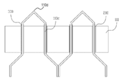
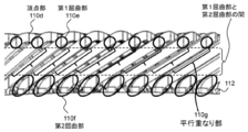
- a flat wire having a rectangular cross section is formed into a U shape by bending it in the direction of the rotation axis at the apex 110d in advance by using foam molding or the like, and the stator coil 110 is formed into a slot 200 provided with insulating paper 300. It is inserted in the direction, and the straight portion of the U-shaped portion is inserted into two spaced slots 200 straddling the plurality of slots 200. As shown in FIGS. 7 and 8, the stator coil 110 on the coil end 110a side is close to the apex 110d of the stator coil 110 formed in a U shape, and is between the apex 110d and the stator core 111.
- the stator coil 110 is located between the first bent portion 110e located directly above the portion where the stator coil 110 extends diagonally (parallel overlapping portion 110 g), the stator core 111, and the apex portion 110d and the stator core 111.
- a second bent portion 110f located immediately below the portion where 110 extends diagonally (parallel overlapping portion 110 g) is formed.
- the linear conductor portion 110c protruding on the opposite side in the axial direction of the stator core 111 is twist-molded, and the end portion thereof is welded to the end portion of another stator coil 110 similarly twist-molded.
- stator coil 110 may be formed into a U shape using a mold, or after the stator coil 110 is inserted into the slot 200. It may be molded into a U shape.
- the stator coil 110 is fixed to the insulating paper 300 by a varnish in the slot 200, and the surface of the coil is protected by the insulating paper 300. Further, the insulating paper 300 is fixed to the stator core 111 by a varnish. As a result, reduction or tearing of the thickness due to damage to the surface coating of the insulating paper 300 and the flat wire generated by vibration during rotation of the rotary electric machine 100 is prevented, and deterioration of the insulating property of the rotary electric machine 100 is prevented.
- the varnish not only fixes the stator coil 110 and the stator core 111 via the insulating paper 300, but also functions of heat drawing to guide the heat generated in the stator coil 110 to the stator core 111.
- the portion of the stator coil 110 protruding from the stator core 111 is fixed to the adjacent stator coil 110 by a varnish to suppress the vibration of the stator coil 110 during rotation of the rotary electric machine 100.
- the varnish is liquid and has polyester type, epoxy type, etc., and may be a one-component type or a two-component mixed system.
- the varnish is preferably a heat-curable type that hardens by heating, but may be a room temperature-curable type.
- the varnish may be applied to both the coil end 110a and the welding side coil end 110b, but may be applied only to one of the coil ends 110a and 110b.
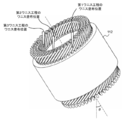
- FIG. 5 is a diagram showing a varnish process of this embodiment, and shows a perspective view of the stator 112.
- the stator 112 in which the stator coil 110 is inserted in the slot 200 is heated before applying the varnish.
- the stator 112 may be heated or the varnish may be heated, but preferably, the stator 112 is heated before the varnish is applied.
- a certain amount of varnish is dropped at a target position using a dispenser, a liquid phase pump, a spray nozzle, or the like, and the dropped varnish is applied to the stator coil 110.
- the term "dripping" in the present specification and claims means that the varnish discharged by the coating device drips toward the stator coil 110, and the varnish particles drip discontinuously or continuously. It may drip. In addition, the size of the varnish particles does not matter.
- the "dropping position” is a position where the varnish discharged by the coating device first comes into contact with the stator coil 110.
- "dropping" is the position of the coating device and the stator coil. Since it is performed a plurality of times with different relative positional relationships, there are also a plurality of "dropping positions".
- the varnish step includes a first varnish step of applying varnish to a position close to the stator core 111 of the stator coil 110 connected to the coil in the slot 200 to form a first varnish portion, and a first varnish.
- the process includes a second varnish step of applying a varnish to a position farther from the stator core 111 (for example, near the apex 110d) to form a second varnish portion. As a result, a non-existent region where no varnish is applied is formed between the first varnish portion and the second varnish portion.
- the varnish hanging on the stator coil 110 moves on the surface of the stator coil 110, but at that time, the varnish comes off from the stator coil 110 and hangs down, and the hanging varnish falls on the stator core 111. It may adhere to the adhesion prohibition area of the stator core 111.
- the adhesion prohibition area of the stator core 111 For example, on the outer peripheral side of the stator 112, when varnish adheres to the outer surface of the stator core 111, which is an adhesion prohibition area, the outer diameter of the stator 112 becomes partially large, and the stator 112 is attached to the housing 130. It disappears.
- the position where the varnish is applied to the stator coil 110 is set to a position close to the stator core 111, so that the amount of movement of the varnish on the coil surface is reduced and the varnish comes off from the stator coil 110. Reduce risk.
- the first varnish portion is formed with the dropping position of the varnish of the stator coil 110 on the outermost periphery as a position close to the stator core 111, and the dropping position of the varnish of the stator coil 110 other than the outermost periphery is set as the apex portion.
- the second varnish portion is formed at a position close to 110d (for example, a portion where a slope is formed by the stator coil 110 slightly below the apex portion 110d).
- Each varnish process is performed in the order of the first varnish process and the second varnish process.
- the varnish applied to the stator coil 110 penetrates the core through the stator coil 110.
- the varnish adheres to the adhesion prohibited area. Therefore, in a state where the varnish has not penetrated into the slot 200, the varnish is applied to the outermost circumference as the first varnish step.
- the permeability of the varnish is better than that after applying the varnish to the other stator coils 110, and the varnish penetrates from the slot 200. It is possible to prevent the overflow of the varnish and suppress the occurrence of defective products.
- the stator 112 may be arranged vertically with its axis, but it is preferable to arrange the stator 112 at an angle and rotate it about the axis from the viewpoint of accessibility of the dropping device.
- the inclination ⁇ 1 of the stator 112 in the first varnish step may be larger than the inclination ⁇ 2 of the stator 112 in the second varnish step.
- the inclination ⁇ of the stator 112 in each varnish step is defined by the angle formed by the axial direction of the stator 112 and the dropping direction (vertical direction) of the varnish.
- the varnish flows down the mesh portion of the stator coil 110. Therefore, when the stator 112 is tilted to the same degree as in the first varnish step, the varnish does not easily penetrate into the slot 200, and the varnish becomes the stator core. It does not reach the inside of 111. Therefore, it is desirable that the inclination of the stator 112 in each varnish step is ⁇ 1> ⁇ 2.
- a varnish is applied to the inner peripheral side of the stator coil 110 at a position closer to the stator core 111 than the second varnish portion to form the third varnish portion.
- a third varnish step of forming may be provided.
- the varnish drips on the inner peripheral side of the stator coil 110, there is a high risk of adhering to the stator core 111. Therefore, when the varnish moves the stator coil 110, the varnish is placed at a position close to the stator core 111 on the inner peripheral side of the stator coil 110 so that the varnish does not come off the stator coil 110 and hang down on the stator core 111. Apply. By doing so, the amount of movement of the varnish on the coil surface can be reduced, the risk of the varnish coming off the stator coil 110 can be reduced, and sufficient varnish permeates into the slot 200 to ensure that the stator coil 110 is secured. Can stick.
- the varnish was applied to the outer peripheral side in the first varnish step, but the varnish may be applied to the inner peripheral side. That is, when the third varnish step is not included, the varnish is dropped on the inner peripheral side in the first varnish step, and the varnish is dropped near the apex 110d in the second varnish step. When the third varnish step is included, the varnish is dropped on the inner peripheral side in the first varnish step, the varnish is dropped near the apex 110d in the second varnish step, and the varnish is dropped on the outer peripheral side in the first varnish step. do.
- the varnish step should be performed in the order of the first varnish step, the second varnish step, and the third varnish step, in the order of the first varnish step, the third varnish step, and the second varnish step. You may go with.
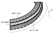
- FIGS. 6 and 7 are perspective views of the stator 112 coated with the varnish of the present embodiment
- FIG. 8 is the stator 112 coated with the varnish of the present embodiment. It is the figure which looked at the coil end 110a of the above from the side.
- the stator coil 110 mounted on the stator 112 is fixed to the stator core 111 by a varnish.
- the portion of the stator coil 110 that protrudes from the end face of the stator core 111 is a portion of the stator coil 110 that is close to the stator core 111 and has a varnish attached to the first varnish portion and above the first varnish portion.
- a second varnish portion to which the varnish is attached and a non-existent region to which the varnish is not attached are provided between the first varnish portion and the second varnish portion.
- the varnish adheres to the adhesion prohibition area provided on the stator core 111 it becomes a defective product.
- the moving distance of the varnish of the outermost coil on the coil surface is short. Therefore, it is possible to prevent the varnish from dripping and suppress the occurrence of defective products.
- the non-existent region to which the varnish is not attached is formed between the first bent portion 110e and the second bent portion 110f.
- the varnish dropped on the apex portion 110d may stay at the first bent portion 110e of the stator coil 110, and the retained varnish may hang down from the first bent portion 110e and adhere to the stator core 111.
- the second bent portion 110f is close to the stator core 111 and the stretching direction is changed by the second bent portion 110f so that the stator coil 110 is accommodated in the slot 200, the stator core 111 is more than the second bent portion 110f.
- the gap between the stator coils 110 adjacent to each other in the circumferential direction becomes large, and a space is created.
- the varnish when the varnish is dropped on the stator core 111 side of the second bent portion 110f, the dropped varnish falls into the space between the stator coils 110 and adheres to the adhesion prohibition area of the stator core 111. , It becomes a defective product. Therefore, the portion below the second bent portion 110f is not suitable as the varnish dropping position. Therefore, by providing the lower end of the first varnish portion and the upper end of the second varnish portion between the first bent portion 110e and the second bent portion 110f of the stator coil 110, the varnish stays in the stator coil 110. It can be suppressed, and the risk of the varnish hanging from the stator coil 110 adhering to the stator core 111 can be reduced.
- the varnish flowing along the stator coil 110 hangs down and the varnish reaches the end of the stator core 111. Adhesion can be suppressed.
- the upper end portion of the first varnish portion is a parallel overlapping portion 110 g in which the stator 112 is viewed from the direction perpendicular to the axis and the adjacent stator coils 110 are arranged in parallel.
- the first varnish portion is formed so that the upper end is arranged.
- the stator coils 110 may be arranged so as to overlap in parallel with a gap.
- the varnish is dropped onto the coil of the rotating stator core 111. At this time, since the varnish accumulated in the first bent portion 110e hangs down, the varnish dropping position is set to a position closer to the stator core 111 than the first bent portion 110e.
- the stator is dropped by dropping the varnish on the parallel overlapping portion 110 g in which the adjacent coils form a parallel gap between the first bent portion 110e and the second bent portion 110f.
- the varnish flowing along the coil 110 hangs down to prevent adhesion to the stator core 111.
- the present invention is not limited to the above-described embodiment, and includes various modifications and equivalent configurations within the scope of the appended claims.
- the above-described examples have been described in detail in order to explain the present invention in an easy-to-understand manner, and the present invention is not necessarily limited to those having all the described configurations.
- a part of the configuration of one embodiment may be replaced with the configuration of another embodiment.
- the configuration of another embodiment may be added to the configuration of one embodiment.
- other configurations may be added / deleted / replaced with respect to a part of the configurations of each embodiment.
Landscapes
- Engineering & Computer Science (AREA)
- Power Engineering (AREA)
- Manufacturing & Machinery (AREA)
- Manufacture Of Motors, Generators (AREA)
- Insulation, Fastening Of Motor, Generator Windings (AREA)
Priority Applications (3)
| Application Number | Priority Date | Filing Date | Title |
|---|---|---|---|
| CN202180014263.6A CN115088166A (zh) | 2020-03-25 | 2021-01-15 | 旋转电机的定子的制造方法、旋转电机的定子以及旋转电机 |
| JP2022509306A JP7308351B2 (ja) | 2020-03-25 | 2021-01-15 | 回転電機の固定子の製造方法、回転電機の固定子、及び回転電機 |
| US17/798,777 US12231009B2 (en) | 2020-03-25 | 2021-01-15 | Method for manufacturing stator of rotating electric machine, stator of rotating electric machine, and rotating electric machine |
Applications Claiming Priority (2)
| Application Number | Priority Date | Filing Date | Title |
|---|---|---|---|
| JP2020-055135 | 2020-03-25 | ||
| JP2020055135 | 2020-03-25 |
Publications (1)
| Publication Number | Publication Date |
|---|---|
| WO2021192531A1 true WO2021192531A1 (ja) | 2021-09-30 |
Family
ID=77891365
Family Applications (1)
| Application Number | Title | Priority Date | Filing Date |
|---|---|---|---|
| PCT/JP2021/001187 Ceased WO2021192531A1 (ja) | 2020-03-25 | 2021-01-15 | 回転電機の固定子の製造方法、回転電機の固定子、及び回転電機 |
Country Status (4)
| Country | Link |
|---|---|
| US (1) | US12231009B2 (enExample) |
| JP (1) | JP7308351B2 (enExample) |
| CN (1) | CN115088166A (enExample) |
| WO (1) | WO2021192531A1 (enExample) |
Families Citing this family (2)
| Publication number | Priority date | Publication date | Assignee | Title |
|---|---|---|---|---|
| US20240339902A1 (en) * | 2023-04-04 | 2024-10-10 | Ford Global Technologies, Llc | Method of varnish trickling to improve emachine durability |
| CN119324611B (zh) * | 2024-11-05 | 2025-06-24 | 苏州精源自动化设备有限公司 | 一种定子滴漆机及多角度倾斜的轮毂电机定子的滴漆方法 |
Citations (3)
| Publication number | Priority date | Publication date | Assignee | Title |
|---|---|---|---|---|
| WO2005027320A1 (ja) * | 2003-09-10 | 2005-03-24 | Aisin Aw Co., Ltd. | 回転電機製造装置及び回転電機製造方法 |
| JP2010178554A (ja) * | 2009-01-30 | 2010-08-12 | Nissan Motor Co Ltd | ステータコアのワニス含浸方法 |
| JP2016116260A (ja) * | 2014-12-11 | 2016-06-23 | トヨタ自動車株式会社 | ステータコアとコイルとを備えたステータの製造方法 |
Family Cites Families (6)
| Publication number | Priority date | Publication date | Assignee | Title |
|---|---|---|---|---|
| JPH10146028A (ja) * | 1996-11-13 | 1998-05-29 | Toyota Motor Corp | モータコイルの製造方法 |
| JP4872594B2 (ja) | 2006-10-23 | 2012-02-08 | トヨタ自動車株式会社 | ワニス処理方法 |
| JP6142561B2 (ja) * | 2013-02-12 | 2017-06-07 | 日産自動車株式会社 | ステータコイルへのワニスの含浸方法及び含浸装置並びにステータコイル |
| JP5962607B2 (ja) * | 2013-07-23 | 2016-08-03 | トヨタ自動車株式会社 | 回転電機ステータ及びその製造方法 |
| JP2017041916A (ja) * | 2014-01-07 | 2017-02-23 | 日立オートモティブシステムズ株式会社 | 回転電機の固定子、これを備えた回転電機、及びこれらの製造方法 |
| JP2020010558A (ja) * | 2018-07-11 | 2020-01-16 | アイシン・エィ・ダブリュ株式会社 | ステータの製造方法 |
-
2021
- 2021-01-15 JP JP2022509306A patent/JP7308351B2/ja active Active
- 2021-01-15 WO PCT/JP2021/001187 patent/WO2021192531A1/ja not_active Ceased
- 2021-01-15 CN CN202180014263.6A patent/CN115088166A/zh active Pending
- 2021-01-15 US US17/798,777 patent/US12231009B2/en active Active
Patent Citations (3)
| Publication number | Priority date | Publication date | Assignee | Title |
|---|---|---|---|---|
| WO2005027320A1 (ja) * | 2003-09-10 | 2005-03-24 | Aisin Aw Co., Ltd. | 回転電機製造装置及び回転電機製造方法 |
| JP2010178554A (ja) * | 2009-01-30 | 2010-08-12 | Nissan Motor Co Ltd | ステータコアのワニス含浸方法 |
| JP2016116260A (ja) * | 2014-12-11 | 2016-06-23 | トヨタ自動車株式会社 | ステータコアとコイルとを備えたステータの製造方法 |
Also Published As
| Publication number | Publication date |
|---|---|
| JPWO2021192531A1 (enExample) | 2021-09-30 |
| US20230109194A1 (en) | 2023-04-06 |
| US12231009B2 (en) | 2025-02-18 |
| CN115088166A (zh) | 2022-09-20 |
| JP7308351B2 (ja) | 2023-07-13 |
Similar Documents
| Publication | Publication Date | Title |
|---|---|---|
| JP6122148B2 (ja) | 回転電機 | |
| US7683516B2 (en) | Production method for rotating electric machine and stator coils, and electric power steering motor | |
| JP5937701B2 (ja) | 回転機及び電動車両 | |
| JP3651491B2 (ja) | モータのコイル端末固定方法 | |
| JP6402257B2 (ja) | 固定子コイル、これを備えた固定子、およびこれを備えた回転電機 | |
| KR101677074B1 (ko) | 전기 기계 | |
| JP6616362B2 (ja) | ブラシレスモータ及び固定子の巻線方法 | |
| CN113258704A (zh) | 线圈骨架、定子铁芯及分布绕组径向间隙型旋转电机 | |
| JP2003032939A (ja) | 電動機 | |
| CN103795194B (zh) | 旋转电机的定子制造方法 | |
| JP2002272046A (ja) | 回転電機の固定子及びその製造方法 | |
| EP3840186A1 (en) | Rotating electric machine | |
| EP3790170A1 (en) | Rotating machine and insulator | |
| WO2021192531A1 (ja) | 回転電機の固定子の製造方法、回転電機の固定子、及び回転電機 | |
| CN103580328A (zh) | 转子、旋转电机和转子的制造方法 | |
| JP7061194B2 (ja) | 回転電機の固定子及びその製造方法 | |
| CN108028564A (zh) | 转子、配备转子的旋转电机、以及转子的制造方法 | |
| JPH1175334A (ja) | 車両用交流発電機の固定子及びその分解方法 | |
| JP2023104065A (ja) | バスバーユニット | |
| JP7324874B2 (ja) | 回転電機の固定子、回転電機用絶縁部材、及び回転電機 | |
| JP6279122B1 (ja) | 回転電機 | |
| JPH07135745A (ja) | 電動機のコア | |
| JP2005176463A (ja) | モータ | |
| JP2024154667A (ja) | 固定子の製造方法 | |
| JP6001447B2 (ja) | 結線構造、回転機、電動車両及び結線方法 |
Legal Events
| Date | Code | Title | Description |
|---|---|---|---|
| 121 | Ep: the epo has been informed by wipo that ep was designated in this application |
Ref document number: 21774394 Country of ref document: EP Kind code of ref document: A1 |
|
| ENP | Entry into the national phase |
Ref document number: 2022509306 Country of ref document: JP Kind code of ref document: A |
|
| NENP | Non-entry into the national phase |
Ref country code: DE |
|
| 122 | Ep: pct application non-entry in european phase |
Ref document number: 21774394 Country of ref document: EP Kind code of ref document: A1 |