WO2021192531A1 - Method for manufacturing stator for dynamo-electric machine, stator for dynamo-electric machine, and dynamo-electric machine - Google Patents
Method for manufacturing stator for dynamo-electric machine, stator for dynamo-electric machine, and dynamo-electric machine Download PDFInfo
- Publication number
- WO2021192531A1 WO2021192531A1 PCT/JP2021/001187 JP2021001187W WO2021192531A1 WO 2021192531 A1 WO2021192531 A1 WO 2021192531A1 JP 2021001187 W JP2021001187 W JP 2021001187W WO 2021192531 A1 WO2021192531 A1 WO 2021192531A1
- Authority
- WO
- WIPO (PCT)
- Prior art keywords
- varnish
- stator
- coil
- electric machine
- rotary electric
- Prior art date
Links
Images


Classifications
-
- H—ELECTRICITY
- H02—GENERATION; CONVERSION OR DISTRIBUTION OF ELECTRIC POWER
- H02K—DYNAMO-ELECTRIC MACHINES
- H02K15/00—Methods or apparatus specially adapted for manufacturing, assembling, maintaining or repairing of dynamo-electric machines
- H02K15/12—Impregnating, heating or drying of windings, stators, rotors or machines
-
- H—ELECTRICITY
- H02—GENERATION; CONVERSION OR DISTRIBUTION OF ELECTRIC POWER
- H02K—DYNAMO-ELECTRIC MACHINES
- H02K1/00—Details of the magnetic circuit
- H02K1/06—Details of the magnetic circuit characterised by the shape, form or construction
- H02K1/12—Stationary parts of the magnetic circuit
- H02K1/16—Stator cores with slots for windings
-
- H—ELECTRICITY
- H02—GENERATION; CONVERSION OR DISTRIBUTION OF ELECTRIC POWER
- H02K—DYNAMO-ELECTRIC MACHINES
- H02K3/00—Details of windings
- H02K3/30—Windings characterised by the insulating material
-
- H—ELECTRICITY
- H02—GENERATION; CONVERSION OR DISTRIBUTION OF ELECTRIC POWER
- H02K—DYNAMO-ELECTRIC MACHINES
- H02K3/00—Details of windings
- H02K3/32—Windings characterised by the shape, form or construction of the insulation
- H02K3/34—Windings characterised by the shape, form or construction of the insulation between conductors or between conductor and core, e.g. slot insulation
- H02K3/345—Windings characterised by the shape, form or construction of the insulation between conductors or between conductor and core, e.g. slot insulation between conductor and core, e.g. slot insulation
-
- H—ELECTRICITY
- H02—GENERATION; CONVERSION OR DISTRIBUTION OF ELECTRIC POWER
- H02K—DYNAMO-ELECTRIC MACHINES
- H02K3/00—Details of windings
- H02K3/46—Fastening of windings on the stator or rotor structure
- H02K3/50—Fastening of winding heads, equalising connectors, or connections thereto
-
- Y—GENERAL TAGGING OF NEW TECHNOLOGICAL DEVELOPMENTS; GENERAL TAGGING OF CROSS-SECTIONAL TECHNOLOGIES SPANNING OVER SEVERAL SECTIONS OF THE IPC; TECHNICAL SUBJECTS COVERED BY FORMER USPC CROSS-REFERENCE ART COLLECTIONS [XRACs] AND DIGESTS
- Y02—TECHNOLOGIES OR APPLICATIONS FOR MITIGATION OR ADAPTATION AGAINST CLIMATE CHANGE
- Y02T—CLIMATE CHANGE MITIGATION TECHNOLOGIES RELATED TO TRANSPORTATION
- Y02T10/00—Road transport of goods or passengers
- Y02T10/60—Other road transportation technologies with climate change mitigation effect
- Y02T10/64—Electric machine technologies in electromobility
Definitions
- the present invention relates to a method for manufacturing a stator of a rotary electric machine.
- stator that houses the coil in the slot formed in the circumferential direction.
- the coil housed in the slot is fixed by a varnish.
- Patent Document 1 Japanese Patent Application Laid-Open No. 2008-109732
- the stator core is held in a posture in which the coil end of the coil mounted on the stator core is up and down, and the coil is held.
- the varnish is injected from the upper surface of the upper coil end protruding from the upper end surface of the stator core, and the varnish impregnating and flowing down from the upper side of the upper coil end protrudes from the lower end surface of the stator core of the coil.
- the varnish is impregnated to the vicinity of the position where gelation started in the first supply step, and then gelation occurs.
- a varnish treatment method is described, which comprises a second supply step of supplying the varnish by controlling the supply amount so as to start (see, for example, claim 1).
- a typical example of the invention disclosed in the present application is as follows. That is, it is a method of manufacturing a stator of a rotary electric machine in which a coil is wound around a stator core, and the coil is arranged on the outermost outer circumference or the innermost outer circumference of a coil end portion in which the coil protrudes from the stator core.
- a second varnish step of forming the second varnish portion is provided so as to provide a non-existing region where the varnish is not applied between the first varnish portion and the second varnish portion.
- FIG. 5 is a cross-sectional view taken along the line AA of the rotary electric machine shown in FIG. It is a perspective view of a stator. It is a schematic diagram of the segment of the stator coil shown in FIG. It is a figure which shows the varnish process. It is a perspective view of the stator coated with varnish. It is a perspective view of the stator coated with varnish. It is the figure which looked at the coil end of the stator coated with varnish from the side.
- the rotary electric machine of this embodiment uses a flat wire capable of miniaturization and high output, it is a rotary electric machine suitable for use in traveling an automobile.
- Vehicles that use a rotary electric machine include a hybrid type electric vehicle (HEV) that has both an engine and a rotary electric machine, and an electric vehicle (EV) that runs only on the rotary electric machine without using an engine.
- HEV hybrid type electric vehicle
- EV electric vehicle
- the rotary electric machine described can be applied to any type. In the following, a rotary electric machine used in a hybrid type automobile will be described as an example.
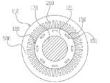
- FIG. 1 is a cross-sectional view of a rotary electric machine 100 according to an embodiment of the present invention.
- the rotary electric machine 100 is a three-phase electric motor with a built-in permanent magnet.
- the rotary electric machine 100 operates as an electric machine in which the stator 120 rotates when the stator coil 110 is wound around the stator core (stator core) 111 and a three-phase AC current is supplied to the stator coil 110.
- the rotary electric machine 100 When the rotary electric machine 100 is driven by the engine, it operates as a generator that generates three-phase alternating current. That is, the above functions can be selectively used depending on the traveling state of the automobile.
- the rotary electric machine 100 has a housing 130 and a stator 112 fixed to the housing 130.
- the stator 112 has a stator coil 110 and a stator core 111 as described above.
- a rotor 120 is rotatably arranged via a gap 140.
- the rotor 120 includes a rotor core 121, a permanent magnet 150, and a non-magnetic backing plate 160.
- the rotor core 121 is fixed to a columnar shaft 170.
- the axial direction of the shaft 170 is referred to as “axial direction”
- the direction of rotation around the axial center is referred to as “circumferential direction”
- the radial direction centered on the axial center is referred to as “diameter direction”.
- the housing 130 has an end bracket 180 provided with bearings 10A and 10B, and the shaft 170 is rotatably held by these bearings 10A and 10B.
- the shaft 170 is provided with a resolver 190 that detects the position of the pole of the rotor 120 and the rotation speed.
- FIG. 2 is a cross-sectional view taken along the line AA of the rotary electric machine 100 shown in FIG.
- the description of the housing 130 and the stator coil 110 is omitted.
- a plurality of slots 200 extending in the axial direction are arranged at equal intervals in the circumferential direction.
- the number of slots 200 is, for example, 48 in this embodiment.
- the stator coil 110 is housed in the slot 200.
- insulating paper (so-called slot liner) is arranged in each slot 200.
- the insulating paper is arranged between the stator coils 110 inserted into the slot 200 and between the stator coil 110 and the inner surface of the slot 200, and is arranged between the stator coils 110 or between the stator coil 110 and the slot 200.
- the insulation withstand voltage between the inner surface and the inner surface is improved.
- the insulating paper is, for example, an insulating sheet of heat-resistant polyamide paper, and has a thickness of about 0.1 to 0.5 mm.
- rectangular parallelepiped magnet insertion holes are arranged at equal intervals in the circumferential direction in the vicinity of the outer peripheral portion.
- Permanent magnets 150 are embedded in each magnet insertion hole and fixed with an adhesive or the like.
- the circumferential width of the magnet insertion hole is formed to be larger than the circumferential width of the permanent magnet 150, and magnetic voids 151 are formed on both sides of the permanent magnet 150.
- the magnetic void 151 may be embedded with an adhesive, or may be integrally solidified with the permanent magnet 150 with a resin.
- the magnetization direction of the permanent magnet 150 is in the radial direction, and the direction of the magnetization direction is reversed for each field magnetic pole. That is, if the surface on the stator side of the permanent magnet 150 for forming a certain magnetic pole is the north pole and the surface on the shaft side is the south pole, the surface on the stator side of the permanent magnet 150 forming the adjacent magnetic pole is Is the south pole, and the surface on the shaft side is the north pole.
- eight permanent magnets 150 are magnetized and arranged so that the magnetization direction changes alternately for each magnetic pole at equal intervals in the circumferential direction, and the rotor 120 forms eight poles.
- the permanent magnet 150 may be embedded in the magnet insertion hole of the rotor core 121 after being magnetized, or may be inserted into the magnet insertion hole of the rotor core 121 before being magnetized, and then magnetized by applying a strong magnetic field. You may try to do it.
- the magnetized permanent magnet 150 has a strong magnetic force, and if the magnet is magnetized before fixing the permanent magnet 150 to the stator 112, it is strong between the permanent magnet 150 and the rotor iron core 121 when the permanent magnet 150 is fixed. A suction force is generated, and this suction force hinders the work. Further, due to the strong attractive force, dust such as iron powder may adhere to the permanent magnet 150. Therefore, it is desirable to magnetize the permanent magnet 150 after inserting it into the magnet insertion hole of the rotor core 121 in order to improve the productivity of the rotary electric machine 100.
- FIG. 3 is a perspective view of the stator 112.
- the stator 112 is fixed to the inner peripheral side of the housing 130 and has a cylindrical stator core 111 and a stator coil 110 mounted on the stator core 111.
- a U-shaped coil end 110a of a plurality of stator coils 110 is formed at one end of the stator core 111 in the axial direction.
- a welded side coil end 110b in which welded portions of the stator coils 110 are arranged in a circle is formed.
- the coil end 110b on the welding side is welded by, for example, TIG (Tungsten Inert Gas).
- TIG Transmission Inert Gas
- the stator core 111 is made of laminated electromagnetic steel plate (for example, silicon steel plate) 500, and the electromagnetic steel plate 500 has a thickness of about 0.05 to 1 mm, is formed by punching or etching, and is laminated. After that, it is fixed by welding. The electromagnetic steel sheets 500 laminated by this welding are joined to suppress deformation of the electrical steel sheets 500 due to a tightening force at the time of press fitting into the housing 130.
- laminated electromagnetic steel plate for example, silicon steel plate
- the electromagnetic steel plate 500 has a thickness of about 0.05 to 1 mm, is formed by punching or etching, and is laminated. After that, it is fixed by welding.
- the electromagnetic steel sheets 500 laminated by this welding are joined to suppress deformation of the electrical steel sheets 500 due to a tightening force at the time of press fitting into the housing 130.
- the stator core 111 is fitted and fixed to the inside of the above-mentioned cylindrical housing 130 by shrink fitting.
- a stator core 111 is first arranged, and a housing 130 whose inner diameter has been expanded by thermal expansion by heating in advance is fitted into the stator core 111.
- the housing 130 is cooled to shrink the inner diameter, and the outer peripheral portion of the stator core 111 is tightened by the heat shrinkage.
- the stator core 111 is set so that the inner diameter dimension of the housing 130 is smaller than the outer diameter dimension of the stator core 111 by a predetermined value so that the stator core 111 does not slip with respect to the housing 130 due to the reaction of the torque of the stator 112 during operation. Set. As a result, the stator core 111 is firmly fixed in the housing 130 by shrink fitting. The difference between the outer diameter of the stator core 111 and the inner diameter of the housing 130 at room temperature is called the tightening allowance, and by setting this tightening allowance assuming the maximum torque of the rotary electric machine 100, the housing 130 is tightened to a predetermined degree.
- the stator core 111 can be held by force.
- the stator core 111 is not limited to the case where it is fitted and fixed by shrink fitting, and may be fitted and fixed to the housing 130 by press fitting.
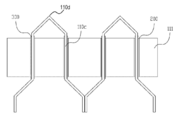
- FIG. 4 is a schematic view of a segment of the stator coil 110 shown in FIG.
- a flat wire is used for the stator coil 110, and the stator coil 110 is wound in a distributed winding manner.
- a surface coating such as polyimide-based, polyester-based, polyesterimide-based, or polyamide-imide-based is provided on the flat wire, but in this embodiment, the material and surface shape of the coil surface are not limited.
- the distributed winding is a winding method in which the stator coil 110 is housed in slots 200 that are separated from each other across a plurality of slots 200.
- the present invention can also be applied to a stator 112 having a stator coil 110 of centralized winding instead of distributed winding.
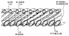
- a flat wire having a rectangular cross section is formed into a U shape by bending it in the direction of the rotation axis at the apex 110d in advance by using foam molding or the like, and the stator coil 110 is formed into a slot 200 provided with insulating paper 300. It is inserted in the direction, and the straight portion of the U-shaped portion is inserted into two spaced slots 200 straddling the plurality of slots 200. As shown in FIGS. 7 and 8, the stator coil 110 on the coil end 110a side is close to the apex 110d of the stator coil 110 formed in a U shape, and is between the apex 110d and the stator core 111.
- the stator coil 110 is located between the first bent portion 110e located directly above the portion where the stator coil 110 extends diagonally (parallel overlapping portion 110 g), the stator core 111, and the apex portion 110d and the stator core 111.
- a second bent portion 110f located immediately below the portion where 110 extends diagonally (parallel overlapping portion 110 g) is formed.
- the linear conductor portion 110c protruding on the opposite side in the axial direction of the stator core 111 is twist-molded, and the end portion thereof is welded to the end portion of another stator coil 110 similarly twist-molded.
- stator coil 110 may be formed into a U shape using a mold, or after the stator coil 110 is inserted into the slot 200. It may be molded into a U shape.
- the stator coil 110 is fixed to the insulating paper 300 by a varnish in the slot 200, and the surface of the coil is protected by the insulating paper 300. Further, the insulating paper 300 is fixed to the stator core 111 by a varnish. As a result, reduction or tearing of the thickness due to damage to the surface coating of the insulating paper 300 and the flat wire generated by vibration during rotation of the rotary electric machine 100 is prevented, and deterioration of the insulating property of the rotary electric machine 100 is prevented.
- the varnish not only fixes the stator coil 110 and the stator core 111 via the insulating paper 300, but also functions of heat drawing to guide the heat generated in the stator coil 110 to the stator core 111.
- the portion of the stator coil 110 protruding from the stator core 111 is fixed to the adjacent stator coil 110 by a varnish to suppress the vibration of the stator coil 110 during rotation of the rotary electric machine 100.
- the varnish is liquid and has polyester type, epoxy type, etc., and may be a one-component type or a two-component mixed system.
- the varnish is preferably a heat-curable type that hardens by heating, but may be a room temperature-curable type.
- the varnish may be applied to both the coil end 110a and the welding side coil end 110b, but may be applied only to one of the coil ends 110a and 110b.
- FIG. 5 is a diagram showing a varnish process of this embodiment, and shows a perspective view of the stator 112.
- the stator 112 in which the stator coil 110 is inserted in the slot 200 is heated before applying the varnish.
- the stator 112 may be heated or the varnish may be heated, but preferably, the stator 112 is heated before the varnish is applied.
- a certain amount of varnish is dropped at a target position using a dispenser, a liquid phase pump, a spray nozzle, or the like, and the dropped varnish is applied to the stator coil 110.
- the term "dripping" in the present specification and claims means that the varnish discharged by the coating device drips toward the stator coil 110, and the varnish particles drip discontinuously or continuously. It may drip. In addition, the size of the varnish particles does not matter.
- the "dropping position” is a position where the varnish discharged by the coating device first comes into contact with the stator coil 110.
- "dropping" is the position of the coating device and the stator coil. Since it is performed a plurality of times with different relative positional relationships, there are also a plurality of "dropping positions".
- the varnish step includes a first varnish step of applying varnish to a position close to the stator core 111 of the stator coil 110 connected to the coil in the slot 200 to form a first varnish portion, and a first varnish.
- the process includes a second varnish step of applying a varnish to a position farther from the stator core 111 (for example, near the apex 110d) to form a second varnish portion. As a result, a non-existent region where no varnish is applied is formed between the first varnish portion and the second varnish portion.
- the varnish hanging on the stator coil 110 moves on the surface of the stator coil 110, but at that time, the varnish comes off from the stator coil 110 and hangs down, and the hanging varnish falls on the stator core 111. It may adhere to the adhesion prohibition area of the stator core 111.
- the adhesion prohibition area of the stator core 111 For example, on the outer peripheral side of the stator 112, when varnish adheres to the outer surface of the stator core 111, which is an adhesion prohibition area, the outer diameter of the stator 112 becomes partially large, and the stator 112 is attached to the housing 130. It disappears.
- the position where the varnish is applied to the stator coil 110 is set to a position close to the stator core 111, so that the amount of movement of the varnish on the coil surface is reduced and the varnish comes off from the stator coil 110. Reduce risk.
- the first varnish portion is formed with the dropping position of the varnish of the stator coil 110 on the outermost periphery as a position close to the stator core 111, and the dropping position of the varnish of the stator coil 110 other than the outermost periphery is set as the apex portion.
- the second varnish portion is formed at a position close to 110d (for example, a portion where a slope is formed by the stator coil 110 slightly below the apex portion 110d).
- Each varnish process is performed in the order of the first varnish process and the second varnish process.
- the varnish applied to the stator coil 110 penetrates the core through the stator coil 110.
- the varnish adheres to the adhesion prohibited area. Therefore, in a state where the varnish has not penetrated into the slot 200, the varnish is applied to the outermost circumference as the first varnish step.
- the permeability of the varnish is better than that after applying the varnish to the other stator coils 110, and the varnish penetrates from the slot 200. It is possible to prevent the overflow of the varnish and suppress the occurrence of defective products.
- the stator 112 may be arranged vertically with its axis, but it is preferable to arrange the stator 112 at an angle and rotate it about the axis from the viewpoint of accessibility of the dropping device.
- the inclination ⁇ 1 of the stator 112 in the first varnish step may be larger than the inclination ⁇ 2 of the stator 112 in the second varnish step.
- the inclination ⁇ of the stator 112 in each varnish step is defined by the angle formed by the axial direction of the stator 112 and the dropping direction (vertical direction) of the varnish.
- the varnish flows down the mesh portion of the stator coil 110. Therefore, when the stator 112 is tilted to the same degree as in the first varnish step, the varnish does not easily penetrate into the slot 200, and the varnish becomes the stator core. It does not reach the inside of 111. Therefore, it is desirable that the inclination of the stator 112 in each varnish step is ⁇ 1> ⁇ 2.
- a varnish is applied to the inner peripheral side of the stator coil 110 at a position closer to the stator core 111 than the second varnish portion to form the third varnish portion.
- a third varnish step of forming may be provided.
- the varnish drips on the inner peripheral side of the stator coil 110, there is a high risk of adhering to the stator core 111. Therefore, when the varnish moves the stator coil 110, the varnish is placed at a position close to the stator core 111 on the inner peripheral side of the stator coil 110 so that the varnish does not come off the stator coil 110 and hang down on the stator core 111. Apply. By doing so, the amount of movement of the varnish on the coil surface can be reduced, the risk of the varnish coming off the stator coil 110 can be reduced, and sufficient varnish permeates into the slot 200 to ensure that the stator coil 110 is secured. Can stick.
- the varnish was applied to the outer peripheral side in the first varnish step, but the varnish may be applied to the inner peripheral side. That is, when the third varnish step is not included, the varnish is dropped on the inner peripheral side in the first varnish step, and the varnish is dropped near the apex 110d in the second varnish step. When the third varnish step is included, the varnish is dropped on the inner peripheral side in the first varnish step, the varnish is dropped near the apex 110d in the second varnish step, and the varnish is dropped on the outer peripheral side in the first varnish step. do.
- the varnish step should be performed in the order of the first varnish step, the second varnish step, and the third varnish step, in the order of the first varnish step, the third varnish step, and the second varnish step. You may go with.
- FIGS. 6 and 7 are perspective views of the stator 112 coated with the varnish of the present embodiment
- FIG. 8 is the stator 112 coated with the varnish of the present embodiment. It is the figure which looked at the coil end 110a of the above from the side.
- the stator coil 110 mounted on the stator 112 is fixed to the stator core 111 by a varnish.
- the portion of the stator coil 110 that protrudes from the end face of the stator core 111 is a portion of the stator coil 110 that is close to the stator core 111 and has a varnish attached to the first varnish portion and above the first varnish portion.
- a second varnish portion to which the varnish is attached and a non-existent region to which the varnish is not attached are provided between the first varnish portion and the second varnish portion.
- the varnish adheres to the adhesion prohibition area provided on the stator core 111 it becomes a defective product.
- the moving distance of the varnish of the outermost coil on the coil surface is short. Therefore, it is possible to prevent the varnish from dripping and suppress the occurrence of defective products.
- the non-existent region to which the varnish is not attached is formed between the first bent portion 110e and the second bent portion 110f.
- the varnish dropped on the apex portion 110d may stay at the first bent portion 110e of the stator coil 110, and the retained varnish may hang down from the first bent portion 110e and adhere to the stator core 111.
- the second bent portion 110f is close to the stator core 111 and the stretching direction is changed by the second bent portion 110f so that the stator coil 110 is accommodated in the slot 200, the stator core 111 is more than the second bent portion 110f.
- the gap between the stator coils 110 adjacent to each other in the circumferential direction becomes large, and a space is created.
- the varnish when the varnish is dropped on the stator core 111 side of the second bent portion 110f, the dropped varnish falls into the space between the stator coils 110 and adheres to the adhesion prohibition area of the stator core 111. , It becomes a defective product. Therefore, the portion below the second bent portion 110f is not suitable as the varnish dropping position. Therefore, by providing the lower end of the first varnish portion and the upper end of the second varnish portion between the first bent portion 110e and the second bent portion 110f of the stator coil 110, the varnish stays in the stator coil 110. It can be suppressed, and the risk of the varnish hanging from the stator coil 110 adhering to the stator core 111 can be reduced.
- the varnish flowing along the stator coil 110 hangs down and the varnish reaches the end of the stator core 111. Adhesion can be suppressed.
- the upper end portion of the first varnish portion is a parallel overlapping portion 110 g in which the stator 112 is viewed from the direction perpendicular to the axis and the adjacent stator coils 110 are arranged in parallel.
- the first varnish portion is formed so that the upper end is arranged.
- the stator coils 110 may be arranged so as to overlap in parallel with a gap.
- the varnish is dropped onto the coil of the rotating stator core 111. At this time, since the varnish accumulated in the first bent portion 110e hangs down, the varnish dropping position is set to a position closer to the stator core 111 than the first bent portion 110e.
- the stator is dropped by dropping the varnish on the parallel overlapping portion 110 g in which the adjacent coils form a parallel gap between the first bent portion 110e and the second bent portion 110f.
- the varnish flowing along the coil 110 hangs down to prevent adhesion to the stator core 111.
- the present invention is not limited to the above-described embodiment, and includes various modifications and equivalent configurations within the scope of the appended claims.
- the above-described examples have been described in detail in order to explain the present invention in an easy-to-understand manner, and the present invention is not necessarily limited to those having all the described configurations.
- a part of the configuration of one embodiment may be replaced with the configuration of another embodiment.
- the configuration of another embodiment may be added to the configuration of one embodiment.
- other configurations may be added / deleted / replaced with respect to a part of the configurations of each embodiment.
Landscapes
- Engineering & Computer Science (AREA)
- Power Engineering (AREA)
- Manufacturing & Machinery (AREA)
- Manufacture Of Motors, Generators (AREA)
- Insulation, Fastening Of Motor, Generator Windings (AREA)
Abstract
Adhesion of varnish to adhesion-prohibited areas is prevented while satisfying required capabilities in relation to the varnish. A method for manufacturing a stator for a dynamo-electric machine in which a coil is wound on a stator core, said method comprising: a first varnish step in which the coil is positioned on the outermost circumference or the innermost circumference of coil end parts projecting from the stator core, and varnish is dripped onto the coil in a position near the stator core to form a first varnish section; and a second varnish step in which the varnish is dripped on a position farther from the stator core than in the first varnish step, and a second varnish section is formed so as to provide a non-present region in which varnish is not applied between the first varnish section and the second varnish section.
Description
本発明は、回転電機の固定子の製造方法に関する。
The present invention relates to a method for manufacturing a stator of a rotary electric machine.
周方向に形成されるスロットにコイルを収納した固定子がある。スロット内に収容されたコイルは、ワニスによって固定されている。
There is a stator that houses the coil in the slot formed in the circumferential direction. The coil housed in the slot is fixed by a varnish.
本技術分野の背景技術として、特開2008-109732号公報(特許文献1)がある。特開2008-109732号公報には、ステータコアに装着されたコイルにワニスを含浸させるワニス処理方法において、前記ステータコアに装着されたコイルのコイルエンドが上下になる姿勢で前記ステータコアを保持し、前記コイルのうち前記ステータコアの上側端面から突出する上側コイルエンドの上面からワニスを注入し、前記上側コイルエンドの上から下へ含浸流下するワニスが、前記コイルのうち前記ステータコアの下側端面から突出する下側コイルエンドの外部に達するより前にゲル化するように供給量を制御しながら前記ワニスを供給する第1供給工程と、前記第1供給工程で最後に供給されたワニスがゲル化する時間以上の間隔をおいて前記コイルが装着された前記ステータコアを反転させる反転工程と、前記反転工程の後に、前記第1供給工程でゲル化が始まった位置付近まで前記ワニスを含浸させてからゲル化が始まるように供給量を制御して前記ワニスを供給する第2供給工程とを含むことを特徴とするワニス処理方法が記載されている(例えば、請求項1参照)。
As a background technology in this technical field, there is Japanese Patent Application Laid-Open No. 2008-109732 (Patent Document 1). According to Japanese Patent Application Laid-Open No. 2008-109732, in a varnish treatment method for impregnating a coil mounted on a stator core with varnish, the stator core is held in a posture in which the coil end of the coil mounted on the stator core is up and down, and the coil is held. Of the above, the varnish is injected from the upper surface of the upper coil end protruding from the upper end surface of the stator core, and the varnish impregnating and flowing down from the upper side of the upper coil end protrudes from the lower end surface of the stator core of the coil. The first supply step of supplying the varnish while controlling the supply amount so as to gel before reaching the outside of the side coil end, and the time or more for the varnish last supplied in the first supply step to gel. After the reversing step of reversing the stator core to which the coil is mounted and the reversing step, the varnish is impregnated to the vicinity of the position where gelation started in the first supply step, and then gelation occurs. A varnish treatment method is described, which comprises a second supply step of supplying the varnish by controlling the supply amount so as to start (see, for example, claim 1).
このような回転電機では、固定子の製造工程において、コイルに塗布したワニスが固定子の付着禁止エリアに付着して不良品となる問題がある。一方で、付着禁止エリアに付着しないようにワニスの量を減少させると、ワニスによるコイルと絶縁紙の固定、またワニスによる絶縁紙とコアを固定させる固定力が低下することにより、モータ回転時にコイルや絶縁紙が振動によって損傷して絶縁性が低下することでモータの破損や発火が生じるリスクがある。
In such a rotary electric machine, there is a problem that the varnish applied to the coil adheres to the adhesion prohibition area of the stator and becomes a defective product in the stator manufacturing process. On the other hand, if the amount of varnish is reduced so as not to adhere to the adhesion prohibited area, the fixing force of the varnish to fix the coil and the insulating paper and the varnish to fix the insulating paper and the core are reduced, so that the coil during motor rotation There is a risk that the motor may be damaged or ignited due to damage to the insulating paper or the insulating paper due to vibration and deterioration of the insulating property.
このため、十分な量のワニスをスロットに注入してワニスに対する要求性能を満たしつつ、ワニスが付着禁止エリアに付着しないという製品の要求品質を満たす固定子の製造方法が求められている。
Therefore, there is a demand for a stator manufacturing method that satisfies the required performance of the varnish by injecting a sufficient amount of varnish into the slot and the required quality of the product that the varnish does not adhere to the adhesion prohibited area.
本願において開示される発明の代表的な一例を示せば以下の通りである。すなわち、固定子コアにコイルが巻回される回転電機の固定子の製造方法であって、前記コイルが前記固定子コアから突出しているコイルエンド部のうち、最外周又は最内周に配置され、前記固定子コアに近接した位置のコイルにワニスを滴下して第1ワニス部を形成する第1ワニス工程と、前記第1ワニス工程より前記固定子コアから遠い位置にワニスを滴下して、前記第1ワニス部と第2ワニス部の間にワニスが塗布されていない非存在領域を設けるように、第2ワニス部を形成する第2ワニス工程と、を備える。
A typical example of the invention disclosed in the present application is as follows. That is, it is a method of manufacturing a stator of a rotary electric machine in which a coil is wound around a stator core, and the coil is arranged on the outermost outer circumference or the innermost outer circumference of a coil end portion in which the coil protrudes from the stator core. A first varnish step of dropping a varnish onto a coil at a position close to the stator core to form a first varnish portion, and a varnish being dropped at a position farther from the stator core than the first varnish step. A second varnish step of forming the second varnish portion is provided so as to provide a non-existing region where the varnish is not applied between the first varnish portion and the second varnish portion.
本発明によれば、付着禁止エリアへのワニスの付着を防止できる。前述した以外の課題、構成及び効果は、以下の実施例の説明によって明らかにされる。
According to the present invention, it is possible to prevent the varnish from adhering to the adhesion prohibited area. Issues, configurations and effects other than those mentioned above will be clarified by the description of the following examples.
[回転電機] まず始めに、本実施例の回転電機の概略を説明する。本実施例の回転電機は、小型化・高出力化が可能な平角線を用いることから自動車の走行に使用するのが好適な回転電機である。回転電機を使用する自動車には、エンジンと回転電機の両方を備えるハイブリッドタイプの電気自動車(HEV)と、エンジンを用いないで回転電機のみで走行する電気自動車(EV)とがあるが、以下に説明する回転電機はいずれのタイプにも適用できる。以下では、ハイブリッドタイプの自動車に用いられる回転電機を例に説明する。
[Rotary electric machine] First, the outline of the rotary electric machine of this embodiment will be described. Since the rotary electric machine of this embodiment uses a flat wire capable of miniaturization and high output, it is a rotary electric machine suitable for use in traveling an automobile. Vehicles that use a rotary electric machine include a hybrid type electric vehicle (HEV) that has both an engine and a rotary electric machine, and an electric vehicle (EV) that runs only on the rotary electric machine without using an engine. The rotary electric machine described can be applied to any type. In the following, a rotary electric machine used in a hybrid type automobile will be described as an example.
図1は、本発明の実施例の回転電機100の断面図である。この回転電機100は、永久磁石内蔵型の三相電機モータである。回転電機100は、固定子コイル110が固定子鉄心(固定子コア)111に巻回され、固定子コイル110に三相交流電流が供給されると回転子120が回転する電動機として作動する。またエンジンによって回転電機100が駆動されると、三相交流を発電する発電機として作動する。つまり、自動車の走行状態によって、上記機能を選択的に利用することができる。
FIG. 1 is a cross-sectional view of a rotary electric machine 100 according to an embodiment of the present invention. The rotary electric machine 100 is a three-phase electric motor with a built-in permanent magnet. The rotary electric machine 100 operates as an electric machine in which the stator 120 rotates when the stator coil 110 is wound around the stator core (stator core) 111 and a three-phase AC current is supplied to the stator coil 110. When the rotary electric machine 100 is driven by the engine, it operates as a generator that generates three-phase alternating current. That is, the above functions can be selectively used depending on the traveling state of the automobile.
図1に示すように、回転電機100は、ハウジング130と、ハウジング130に固定されている固定子112を有する。固定子112は前述のように固定子コイル110と固定子鉄心111を有している。固定子鉄心111の内側には、回転子120が空隙140を介して回転自在に配設されている。回転子120は回転子鉄心121と永久磁石150と、非磁性体の当て板160とを備えている。回転子鉄心121は円柱状のシャフト170に固定されている。なお、以下の記載では、シャフト170の軸心方向を「軸方向」、軸心を中心として回転する方向を「周方向」、軸心を中心とした放射方向を「径方向」と称する。
As shown in FIG. 1, the rotary electric machine 100 has a housing 130 and a stator 112 fixed to the housing 130. The stator 112 has a stator coil 110 and a stator core 111 as described above. Inside the stator core 111, a rotor 120 is rotatably arranged via a gap 140. The rotor 120 includes a rotor core 121, a permanent magnet 150, and a non-magnetic backing plate 160. The rotor core 121 is fixed to a columnar shaft 170. In the following description, the axial direction of the shaft 170 is referred to as "axial direction", the direction of rotation around the axial center is referred to as "circumferential direction", and the radial direction centered on the axial center is referred to as "diameter direction".
ハウジング130は、軸受10A、10Bが設けられたエンドブラケット180を有し、シャフト170はこれらの軸受10A、10Bにより回転自在に保持されている。シャフト170には、回転子120の極の位置や回転速度を検出するレゾルバ190が設けられている。
The housing 130 has an end bracket 180 provided with bearings 10A and 10B, and the shaft 170 is rotatably held by these bearings 10A and 10B. The shaft 170 is provided with a resolver 190 that detects the position of the pole of the rotor 120 and the rotation speed.
図2は図1に示す回転電機100のA-A線断面図である。なお、図2ではハウジング130、固定子コイル110の記載を省略している。固定子鉄心111には、軸方向に伸びる複数のスロット200が、周方向に等間隔に配置されている。スロット200の数は、たとえば本実施例では48個である。スロット200には固定子コイル110が収容される。
FIG. 2 is a cross-sectional view taken along the line AA of the rotary electric machine 100 shown in FIG. In FIG. 2, the description of the housing 130 and the stator coil 110 is omitted. In the stator core 111, a plurality of slots 200 extending in the axial direction are arranged at equal intervals in the circumferential direction. The number of slots 200 is, for example, 48 in this embodiment. The stator coil 110 is housed in the slot 200.
なお、各スロット200内には、図示していないが絶縁紙(いわゆるスロットライナー)が配置されている。絶縁紙は、スロット200に挿入される固定子コイル110の相互間および固定子コイル110とスロット200の内面との間に配設されて、固定子コイル110間や固定子コイル110とスロット200の内面との間の絶縁耐圧を向上している。なお、絶縁紙は、例えば耐熱ポリアミド紙の絶縁シートであり、厚さは0.1~0.5mm程度である。
Although not shown, insulating paper (so-called slot liner) is arranged in each slot 200. The insulating paper is arranged between the stator coils 110 inserted into the slot 200 and between the stator coil 110 and the inner surface of the slot 200, and is arranged between the stator coils 110 or between the stator coil 110 and the slot 200. The insulation withstand voltage between the inner surface and the inner surface is improved. The insulating paper is, for example, an insulating sheet of heat-resistant polyamide paper, and has a thickness of about 0.1 to 0.5 mm.
回転子鉄心121には、直方体形状の磁石挿入孔が外周部近傍において周方向に等間隔で配置されている。各磁石挿入孔には、永久磁石150が埋め込まれ、接着剤などで固定されている。磁石挿入孔の円周方向の幅は、永久磁石150の円周方向の幅よりも大きく形成されており、永久磁石150の両側には磁気的空隙151が形成されている。この磁気的空隙151は接着剤を埋め込んでもいいし、樹脂で永久磁石150と一体に固めてもよい。
In the rotor core 121, rectangular parallelepiped magnet insertion holes are arranged at equal intervals in the circumferential direction in the vicinity of the outer peripheral portion. Permanent magnets 150 are embedded in each magnet insertion hole and fixed with an adhesive or the like. The circumferential width of the magnet insertion hole is formed to be larger than the circumferential width of the permanent magnet 150, and magnetic voids 151 are formed on both sides of the permanent magnet 150. The magnetic void 151 may be embedded with an adhesive, or may be integrally solidified with the permanent magnet 150 with a resin.
永久磁石150の磁化方向は径方向を向いており、界磁極ごとに磁化方向の向きが反転している。すなわち、ある磁極を形成するための永久磁石150の固定子側の面がN極、シャフト側の面がS極であったならば、隣の磁極を形成する永久磁石150の固定子側の面はS極、シャフト側の面はN極となっている。本実施形態では、8個の永久磁石150が円周方向に等間隔で磁極毎に交互に磁化方向が変わるように磁化されて配置されており、回転子120は8極を形成している。
The magnetization direction of the permanent magnet 150 is in the radial direction, and the direction of the magnetization direction is reversed for each field magnetic pole. That is, if the surface on the stator side of the permanent magnet 150 for forming a certain magnetic pole is the north pole and the surface on the shaft side is the south pole, the surface on the stator side of the permanent magnet 150 forming the adjacent magnetic pole is Is the south pole, and the surface on the shaft side is the north pole. In the present embodiment, eight permanent magnets 150 are magnetized and arranged so that the magnetization direction changes alternately for each magnetic pole at equal intervals in the circumferential direction, and the rotor 120 forms eight poles.
なお、永久磁石150は、磁化したあとに回転子鉄心121の磁石挿入孔に埋め込んでもよいし、磁化する前に回転子鉄心121の磁石挿入孔に挿入し、その後に強力な磁界を与えて磁化するようにしてもよい。
The permanent magnet 150 may be embedded in the magnet insertion hole of the rotor core 121 after being magnetized, or may be inserted into the magnet insertion hole of the rotor core 121 before being magnetized, and then magnetized by applying a strong magnetic field. You may try to do it.
ただし、磁化後の永久磁石150は、磁力が強力であり、固定子112に永久磁石150を固定する前に磁石を着磁すると、永久磁石150の固定時に回転子鉄心121との間に強力な吸引力が生じ、この吸引力が作業の妨げになる。また、強力な吸引力により、永久磁石150に鉄粉などのごみが付着する恐れがある。そのため、永久磁石150を回転子鉄心121の磁石挿入孔に挿入したあとに磁化するほうが、回転電機100の生産性を向上するうえで望ましい。
However, the magnetized permanent magnet 150 has a strong magnetic force, and if the magnet is magnetized before fixing the permanent magnet 150 to the stator 112, it is strong between the permanent magnet 150 and the rotor iron core 121 when the permanent magnet 150 is fixed. A suction force is generated, and this suction force hinders the work. Further, due to the strong attractive force, dust such as iron powder may adhere to the permanent magnet 150. Therefore, it is desirable to magnetize the permanent magnet 150 after inserting it into the magnet insertion hole of the rotor core 121 in order to improve the productivity of the rotary electric machine 100.
[回転電機の固定子] 図3は、固定子112の斜視図である。固定子112はハウジング130の内周側に固定され、円筒状の固定子鉄心111と、この固定子鉄心111に装着される固定子コイル110とを有している。固定子鉄心111の軸方向一方の端部には、複数の固定子コイル110のU字形状をなすコイルエンド110aが形成される。一方、固定子鉄心111の反対側の端部には、固定子コイル110同士の溶接部分が円状に並んだ溶接側コイルエンド110bが形成される。溶接側コイルエンド110bは、例えばTIG(Tungsten Inert Gas)によって溶接されている。なお、図3において、出力取出し線の図示は省略した。
[Stator of rotary electric machine] FIG. 3 is a perspective view of the stator 112. The stator 112 is fixed to the inner peripheral side of the housing 130 and has a cylindrical stator core 111 and a stator coil 110 mounted on the stator core 111. A U-shaped coil end 110a of a plurality of stator coils 110 is formed at one end of the stator core 111 in the axial direction. On the other hand, at the end on the opposite side of the stator core 111, a welded side coil end 110b in which welded portions of the stator coils 110 are arranged in a circle is formed. The coil end 110b on the welding side is welded by, for example, TIG (Tungsten Inert Gas). In FIG. 3, the output take-out line is not shown.
固定子鉄心111は、固定子鉄心111は積層された電磁鋼板(例えばケイ素鋼板)500からなり、電磁鋼板500は厚さが0.05~1mm程度で打ち抜き加工又はエッチング加工で成形され、積層された後に溶接によって固定される。この溶接によって積層された電磁鋼板500は接合され、ハウジング130への圧入時の締付力による電磁鋼板500の変形を抑制する。
In the stator core 111, the stator core 111 is made of laminated electromagnetic steel plate (for example, silicon steel plate) 500, and the electromagnetic steel plate 500 has a thickness of about 0.05 to 1 mm, is formed by punching or etching, and is laminated. After that, it is fixed by welding. The electromagnetic steel sheets 500 laminated by this welding are joined to suppress deformation of the electrical steel sheets 500 due to a tightening force at the time of press fitting into the housing 130.
固定子鉄心111は、上述した円筒状のハウジング130の内側に焼嵌めにより嵌合固定される。具体的な組立て方としては、例えば、先ず固定子鉄心111を配置しておき、この固定子鉄心111に、あらかじめ加熱して熱膨張により内径を広げておいたハウジング130を嵌め込む。次に、ハウジング130を冷却して内径を収縮させることで、その熱収縮により固定子鉄心111の外周部を締め付ける。
The stator core 111 is fitted and fixed to the inside of the above-mentioned cylindrical housing 130 by shrink fitting. As a specific assembly method, for example, a stator core 111 is first arranged, and a housing 130 whose inner diameter has been expanded by thermal expansion by heating in advance is fitted into the stator core 111. Next, the housing 130 is cooled to shrink the inner diameter, and the outer peripheral portion of the stator core 111 is tightened by the heat shrinkage.
固定子鉄心111は、運転時における固定子112のトルクによる反作用によってハウジング130に対して空転しないように、ハウジング130の内径寸法を固定子鉄心111の外径寸法よりも所定値だけ小さくなるように設定する。その結果、焼嵌め嵌合により固定子鉄心111がハウジング130内に強固に固定される。常温における固定子鉄心111の外径とハウジング130の内径との差は締め代と呼ばれ、この締め代を回転電機100の最大トルクを想定して設定することで、ハウジング130は所定の締付力により固定子鉄心111を保持することができる。なお、固定子鉄心111は焼嵌めにより嵌合固定する場合に限定されることはなく、圧入によりハウジング130に嵌合固定することとしてもよい。
The stator core 111 is set so that the inner diameter dimension of the housing 130 is smaller than the outer diameter dimension of the stator core 111 by a predetermined value so that the stator core 111 does not slip with respect to the housing 130 due to the reaction of the torque of the stator 112 during operation. Set. As a result, the stator core 111 is firmly fixed in the housing 130 by shrink fitting. The difference between the outer diameter of the stator core 111 and the inner diameter of the housing 130 at room temperature is called the tightening allowance, and by setting this tightening allowance assuming the maximum torque of the rotary electric machine 100, the housing 130 is tightened to a predetermined degree. The stator core 111 can be held by force. The stator core 111 is not limited to the case where it is fitted and fixed by shrink fitting, and may be fitted and fixed to the housing 130 by press fitting.
[固定子コイル] 次に、固定子コイル110について説明する。図4は図3に示す固定子コイル110のセグメントの模式図である。本実施例では、固定子コイル110には平角線が用いられ、固定子コイル110は分布巻の方式で巻かれている。平角線には、ポリイミド系、ポリエステル系、ポリエステルイミド系、ポリアミドイミド系などの表面被覆が設けられるが、本実施例では、コイル表面の材質や表面形状は問わない。分布巻とは、複数のスロット200を跨いで離間したスロット200に固定子コイル110が収納される巻線方式である。なお、本発明は、分布巻きではなく集中巻の固定子コイル110を有する固定子112にも適用可能である。
[Stator coil] Next, the stator coil 110 will be described. FIG. 4 is a schematic view of a segment of the stator coil 110 shown in FIG. In this embodiment, a flat wire is used for the stator coil 110, and the stator coil 110 is wound in a distributed winding manner. A surface coating such as polyimide-based, polyester-based, polyesterimide-based, or polyamide-imide-based is provided on the flat wire, but in this embodiment, the material and surface shape of the coil surface are not limited. The distributed winding is a winding method in which the stator coil 110 is housed in slots 200 that are separated from each other across a plurality of slots 200. The present invention can also be applied to a stator 112 having a stator coil 110 of centralized winding instead of distributed winding.
断面が矩形状の平角線を、予めフォーム成形などを用いて、頂点部110dで回転軸方向に屈曲してU字形状に成形し、その固定子コイル110を絶縁紙300が設けられたスロット200方向に挿入し、U字部の直線部を複数のスロット200を跨ぐ離間した二つのスロット200に挿入している。コイルエンド110a側の固定子コイル110には、図7、図8に示すように、U字形状に成形された固定子コイル110の頂点部110dに近く、頂点部110dと固定子鉄心111の間で固定子コイル110が斜めに延伸する部分(平行重なり部110g)の直上に位置する第1屈曲部110eと、固定子鉄心111に近く、頂点部110dと固定子鉄心111の間で固定子コイル110が斜めに延伸する部分(平行重なり部110g)の直下に位置する第2屈曲部110fとが形成される。
A flat wire having a rectangular cross section is formed into a U shape by bending it in the direction of the rotation axis at the apex 110d in advance by using foam molding or the like, and the stator coil 110 is formed into a slot 200 provided with insulating paper 300. It is inserted in the direction, and the straight portion of the U-shaped portion is inserted into two spaced slots 200 straddling the plurality of slots 200. As shown in FIGS. 7 and 8, the stator coil 110 on the coil end 110a side is close to the apex 110d of the stator coil 110 formed in a U shape, and is between the apex 110d and the stator core 111. The stator coil 110 is located between the first bent portion 110e located directly above the portion where the stator coil 110 extends diagonally (parallel overlapping portion 110 g), the stator core 111, and the apex portion 110d and the stator core 111. A second bent portion 110f located immediately below the portion where 110 extends diagonally (parallel overlapping portion 110 g) is formed.
その後、固定子鉄心111の軸方向反対側に突出した直線導体部110cを捻り成形し、その端部を同様に捻り成形した他の固定子コイル110の端部と溶接する。このように複数の固定子コイル110を固定子鉄心111のスロット200に挿入し、それらを接続することで1つの相巻線が形成される。
After that, the linear conductor portion 110c protruding on the opposite side in the axial direction of the stator core 111 is twist-molded, and the end portion thereof is welded to the end portion of another stator coil 110 similarly twist-molded. By inserting the plurality of stator coils 110 into the slots 200 of the stator core 111 and connecting them in this way, one phase winding is formed.
上述した固定子コイル110の成形方法は一例を述べただけであり、固定子コイル110は型を用いてU字形状に成形してもよいし、固定子コイル110をスロット200に挿入したのちにU字形状に成形してもよい。
The method for forming the stator coil 110 described above is only an example, and the stator coil 110 may be formed into a U shape using a mold, or after the stator coil 110 is inserted into the slot 200. It may be molded into a U shape.
固定子コイル110は、スロット200内でワニスによって絶縁紙300と固着し、絶縁紙300によってコイルの表面が保護される。また絶縁紙300は、ワニスによって固定子鉄心111に固着される。これにより回転電機100の回転時の振動によって発生する絶縁紙300および平角線の表面被覆の損傷による厚みの減少や破れが防止され、回転電機100の絶縁性の低下が防止される。ワニスは、絶縁紙300を介して、固定子コイル110と固定子鉄心111を固定するだけでなく、固定子コイル110に発生した熱を固定子鉄心111に誘導する熱引きの機能も果たす。
The stator coil 110 is fixed to the insulating paper 300 by a varnish in the slot 200, and the surface of the coil is protected by the insulating paper 300. Further, the insulating paper 300 is fixed to the stator core 111 by a varnish. As a result, reduction or tearing of the thickness due to damage to the surface coating of the insulating paper 300 and the flat wire generated by vibration during rotation of the rotary electric machine 100 is prevented, and deterioration of the insulating property of the rotary electric machine 100 is prevented. The varnish not only fixes the stator coil 110 and the stator core 111 via the insulating paper 300, but also functions of heat drawing to guide the heat generated in the stator coil 110 to the stator core 111.
固定子コイル110の固定子鉄心111から突出した部分は、ワニスによって隣接する固定子コイル110と固着され、回転電機100の回転時の固定子コイル110の振動を抑制している。
The portion of the stator coil 110 protruding from the stator core 111 is fixed to the adjacent stator coil 110 by a varnish to suppress the vibration of the stator coil 110 during rotation of the rotary electric machine 100.
ワニスは、液体性状で、ポリエステル系、エポキシ系などがあり、1液系でも2液混合系でもよい。また、ワニスは、加熱して固まる加熱硬化型が望ましいが、常温硬化型でもよい。
The varnish is liquid and has polyester type, epoxy type, etc., and may be a one-component type or a two-component mixed system. The varnish is preferably a heat-curable type that hardens by heating, but may be a room temperature-curable type.
ワニスは、コイルエンド110a及び溶接側コイルエンド110bの両方に塗布するとよいが、一方のコイルエンド110a、110bのみに塗布してもよい。
The varnish may be applied to both the coil end 110a and the welding side coil end 110b, but may be applied only to one of the coil ends 110a and 110b.
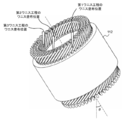
[ワニス工程] 図5は、本実施例のワニス工程を示す図であり、固定子112の斜視図を示す。
[Varnish process] FIG. 5 is a diagram showing a varnish process of this embodiment, and shows a perspective view of the stator 112.
スロット200内に固定子コイル110が挿入された固定子112は、ワニスを塗布する前に加熱される。なお、固定子112を加熱しても、ワニスを加熱してもよいが、望ましくは、固定子112を加熱してからワニスを塗布する。本実施例のワニス工程では、ディスペンサ、液相ポンプ、スプレーノズル等を用いて、狙った位置に定量のワニスを滴下して、滴下したワニスを固定子コイル110に塗布する。本明細書及び特許請求の範囲における「滴下」の語は、塗布装置が吐出したワニスが固定子コイル110に向けて滴り落ちることを意味し、ワニスの粒が非連続で滴り落ちたり、連続で滴り落ちてもよい。また、ワニスの粒子の大きさも問わない。また、「滴下位置」は、塗布装置が吐出したワニスが固定子コイル110に最初に接触する位置であり、通常は、一つの固定子112において、「滴下」は塗布装置と固定子コイルとの相対的位置関係を変えて複数回行われるので、「滴下位置」も複数個所存在する。
The stator 112 in which the stator coil 110 is inserted in the slot 200 is heated before applying the varnish. The stator 112 may be heated or the varnish may be heated, but preferably, the stator 112 is heated before the varnish is applied. In the varnish step of this embodiment, a certain amount of varnish is dropped at a target position using a dispenser, a liquid phase pump, a spray nozzle, or the like, and the dropped varnish is applied to the stator coil 110. The term "dripping" in the present specification and claims means that the varnish discharged by the coating device drips toward the stator coil 110, and the varnish particles drip discontinuously or continuously. It may drip. In addition, the size of the varnish particles does not matter. Further, the "dropping position" is a position where the varnish discharged by the coating device first comes into contact with the stator coil 110. Normally, in one stator 112, "dropping" is the position of the coating device and the stator coil. Since it is performed a plurality of times with different relative positional relationships, there are also a plurality of "dropping positions".
具体的には、ワニス工程は、スロット200内のコイルに繋がる固定子コイル110の固定子鉄心111に近い位置にワニスを塗布して第1ワニス部を形成する第1ワニス工程と、第1ワニス工程よりも固定子鉄心111から遠い位置(例えば、頂点部110d付近)にワニスを塗布して第2ワニス部を形成する第2ワニス工程とを含む。その結果、第1ワニス部と第2ワニス部の間にワニスが塗布されていない非存在領域が形成される。
Specifically, the varnish step includes a first varnish step of applying varnish to a position close to the stator core 111 of the stator coil 110 connected to the coil in the slot 200 to form a first varnish portion, and a first varnish. The process includes a second varnish step of applying a varnish to a position farther from the stator core 111 (for example, near the apex 110d) to form a second varnish portion. As a result, a non-existent region where no varnish is applied is formed between the first varnish portion and the second varnish portion.
ワニス工程において、固定子コイル110に垂れたワニスは固定子コイル110の表面上を移動するが、その際にワニスが固定子コイル110から外れて垂れ、垂れたワニスが固定子鉄心111に落下して固定子鉄心111の付着禁止エリアに付着することがある。
例えば、固定子112の外周側では、付着禁止エリアである固定子鉄心111の外側面にワニスが付着すると、固定子112の外径が部分的に大きくなり、固定子112がハウジング130に取り付けられなくなる。また、固定子112の内周側では、付着禁止エリアである固定子鉄心111の内側面にワニスが付着すると、固定子112の内側に取り付けられる回転子120と干渉して、回転子120を正しい位置に配置できなくなり、回転に支障や不良が生じる。これを防止するために、固定子コイル110へワニスを塗布する位置を固定子鉄心111に近い位置にすることで、ワニスのコイル表面上の移動量を低減し、ワニスが固定子コイル110から外れるリスクを低減する。具体的には、最外周の固定子コイル110のワニスの滴下位置を固定子鉄心111に近い位置として第1ワニス部を形成し、最外周以外の固定子コイル110のワニスの滴下位置を頂点部110dに近い位置(例えば、頂点部110dより少し下の固定子コイル110によって斜面が形成される部分)として第2ワニス部を形成する。第1ワニス工程のワニス滴下位置を第2ワニス工程のワニス滴下位置より固定子鉄心111に近い位置にすることによって、第2ワニス部より固定子鉄心111に近い位置に第1ワニス部が設けられる。よって、ワニスの移動量を低減し、ワニスが固定子コイル110から外れるリスクを低減でき、さらに、スロット200内に十分なワニスが浸透し、固定子コイル110を確実に固着できる。 In the varnish process, the varnish hanging on thestator coil 110 moves on the surface of the stator coil 110, but at that time, the varnish comes off from the stator coil 110 and hangs down, and the hanging varnish falls on the stator core 111. It may adhere to the adhesion prohibition area of the stator core 111.
For example, on the outer peripheral side of thestator 112, when varnish adheres to the outer surface of the stator core 111, which is an adhesion prohibition area, the outer diameter of the stator 112 becomes partially large, and the stator 112 is attached to the housing 130. It disappears. Further, on the inner peripheral side of the stator 112, if varnish adheres to the inner surface of the stator core 111, which is an adhesion prohibition area, it interferes with the rotor 120 attached to the inside of the stator 112, and the rotor 120 is correct. It becomes impossible to place it in the position, and the rotation is hindered or defective. In order to prevent this, the position where the varnish is applied to the stator coil 110 is set to a position close to the stator core 111, so that the amount of movement of the varnish on the coil surface is reduced and the varnish comes off from the stator coil 110. Reduce risk. Specifically, the first varnish portion is formed with the dropping position of the varnish of the stator coil 110 on the outermost periphery as a position close to the stator core 111, and the dropping position of the varnish of the stator coil 110 other than the outermost periphery is set as the apex portion. The second varnish portion is formed at a position close to 110d (for example, a portion where a slope is formed by the stator coil 110 slightly below the apex portion 110d). By setting the varnish dropping position in the first varnish step closer to the stator core 111 than the varnish dropping position in the second varnish step, the first varnish portion is provided at a position closer to the stator core 111 than the second varnish portion. .. Therefore, the amount of movement of the varnish can be reduced, the risk of the varnish coming off the stator coil 110 can be reduced, and moreover, sufficient varnish permeates into the slot 200, and the stator coil 110 can be reliably fixed.
例えば、固定子112の外周側では、付着禁止エリアである固定子鉄心111の外側面にワニスが付着すると、固定子112の外径が部分的に大きくなり、固定子112がハウジング130に取り付けられなくなる。また、固定子112の内周側では、付着禁止エリアである固定子鉄心111の内側面にワニスが付着すると、固定子112の内側に取り付けられる回転子120と干渉して、回転子120を正しい位置に配置できなくなり、回転に支障や不良が生じる。これを防止するために、固定子コイル110へワニスを塗布する位置を固定子鉄心111に近い位置にすることで、ワニスのコイル表面上の移動量を低減し、ワニスが固定子コイル110から外れるリスクを低減する。具体的には、最外周の固定子コイル110のワニスの滴下位置を固定子鉄心111に近い位置として第1ワニス部を形成し、最外周以外の固定子コイル110のワニスの滴下位置を頂点部110dに近い位置(例えば、頂点部110dより少し下の固定子コイル110によって斜面が形成される部分)として第2ワニス部を形成する。第1ワニス工程のワニス滴下位置を第2ワニス工程のワニス滴下位置より固定子鉄心111に近い位置にすることによって、第2ワニス部より固定子鉄心111に近い位置に第1ワニス部が設けられる。よって、ワニスの移動量を低減し、ワニスが固定子コイル110から外れるリスクを低減でき、さらに、スロット200内に十分なワニスが浸透し、固定子コイル110を確実に固着できる。 In the varnish process, the varnish hanging on the
For example, on the outer peripheral side of the
各ワニス工程は、第1ワニス工程、第2ワニス工程の順で行われる。固定子コイル110に塗布されたワニスは固定子コイル110を伝ってコアに浸透する。最外周のコイルからワニスが固定子鉄心111に垂れると、付着禁止エリアにワニスが付着する。このため、スロット200内へワニスが浸透していない状態で、第1ワニス工程として、最外周にワニス塗布をする。固定子鉄心111にワニスが浸透していない状態で最外周にワニス塗布をすることによって、他の固定子コイル110にワニスを塗布した後に塗布するよりも、ワニスの浸透性が良く、スロット200からのワニスの溢れを防止でき、不良品の発生を抑制できる。
Each varnish process is performed in the order of the first varnish process and the second varnish process. The varnish applied to the stator coil 110 penetrates the core through the stator coil 110. When the varnish hangs down from the outermost coil to the stator core 111, the varnish adheres to the adhesion prohibited area. Therefore, in a state where the varnish has not penetrated into the slot 200, the varnish is applied to the outermost circumference as the first varnish step. By applying the varnish to the outermost periphery in a state where the varnish has not penetrated into the stator core 111, the permeability of the varnish is better than that after applying the varnish to the other stator coils 110, and the varnish penetrates from the slot 200. It is possible to prevent the overflow of the varnish and suppress the occurrence of defective products.
本実施例のワニス工程の間、固定子112は軸が垂直に配置してもよいが、滴下装置のアクセス性から固定子112を傾けて配置して、軸を中心に回転させるとよい。特に、第1ワニス工程における固定子112の傾きθ1は、第2ワニス工程における固定子112の傾きθ2より大きくするとよい。なお、各ワニス工程における固定子112の傾きθは、固定子112の軸方向とワニスの滴下方向(鉛直方向)とが成す角で定義し、傾きθ=0では、軸方向が鉛直で、固定子鉄心111の端面が水平となる。
During the varnishing process of this embodiment, the stator 112 may be arranged vertically with its axis, but it is preferable to arrange the stator 112 at an angle and rotate it about the axis from the viewpoint of accessibility of the dropping device. In particular, the inclination θ1 of the stator 112 in the first varnish step may be larger than the inclination θ2 of the stator 112 in the second varnish step. The inclination θ of the stator 112 in each varnish step is defined by the angle formed by the axial direction of the stator 112 and the dropping direction (vertical direction) of the varnish. When the inclination θ = 0, the axial direction is vertical and fixed. The end face of the child core 111 becomes horizontal.
第2ワニス工程では、ワニスは固定子コイル110の網目部分を流下するので、固定子112を第1ワニス工程と同程度に傾けると、ワニスがスロット200内に浸透しにくく、ワニスが固定子鉄心111の内部にまで到達しない。よって、各ワニス工程における固定子112の傾きはθ1>θ2とすることが望ましい。
In the second varnish step, the varnish flows down the mesh portion of the stator coil 110. Therefore, when the stator 112 is tilted to the same degree as in the first varnish step, the varnish does not easily penetrate into the slot 200, and the varnish becomes the stator core. It does not reach the inside of 111. Therefore, it is desirable that the inclination of the stator 112 in each varnish step is θ1> θ2.
また、図示したように第1ワニス工程及び第2ワニス工程に加え、第2ワニス部より固定子鉄心111に近い位置で固定子コイル110の内周側にワニスを塗布して第3ワニス部を形成する第3ワニス工程を設けてもよい。
Further, as shown in the figure, in addition to the first varnish step and the second varnish step, a varnish is applied to the inner peripheral side of the stator coil 110 at a position closer to the stator core 111 than the second varnish portion to form the third varnish portion. A third varnish step of forming may be provided.
固定子コイル110の内周側において、塗布されたワニスが垂れると固定子鉄心111に付着するリスクが高い。そのため、ワニスが固定子コイル110を移動する際に、固定子コイル110から外れて固定子鉄心111に垂れないように、固定子コイル110の内周側では固定子鉄心111に近い位置にワニスを塗布する。そうすることで、コイル表面上のワニスの移動量を低減し、ワニスが固定子コイル110から外れるリスクを低減でき、さらに、スロット200内に十分なワニスが浸透し、固定子コイル110を確実に固着できる。
If the applied varnish drips on the inner peripheral side of the stator coil 110, there is a high risk of adhering to the stator core 111. Therefore, when the varnish moves the stator coil 110, the varnish is placed at a position close to the stator core 111 on the inner peripheral side of the stator coil 110 so that the varnish does not come off the stator coil 110 and hang down on the stator core 111. Apply. By doing so, the amount of movement of the varnish on the coil surface can be reduced, the risk of the varnish coming off the stator coil 110 can be reduced, and sufficient varnish permeates into the slot 200 to ensure that the stator coil 110 is secured. Can stick.
以上の説明では、第1ワニス工程において外周側にワニスを塗布したが、内周側にワニスを塗布してもよい。すなわち、第3ワニス工程を含まない場合、第1ワニス工程において内周側にワニスを滴下し、第2ワニス工程において頂点部110d付近にワニスを滴下する。また、第3ワニス工程を含む場合、第1ワニス工程において内周側にワニスを滴下し、第2ワニス工程において頂点部110d付近にワニスを滴下し、第1ワニス工程において外周側にワニスを滴下する。
In the above description, the varnish was applied to the outer peripheral side in the first varnish step, but the varnish may be applied to the inner peripheral side. That is, when the third varnish step is not included, the varnish is dropped on the inner peripheral side in the first varnish step, and the varnish is dropped near the apex 110d in the second varnish step. When the third varnish step is included, the varnish is dropped on the inner peripheral side in the first varnish step, the varnish is dropped near the apex 110d in the second varnish step, and the varnish is dropped on the outer peripheral side in the first varnish step. do.
第3ワニス工程を含めた場合のワニス工程は、第1ワニス工程、第2ワニス工程、第3ワニス工程の順で行うとよく、第1ワニス工程、第3ワニス工程、第2ワニス工程の順で行ってもよい。
When the third varnish step is included, the varnish step should be performed in the order of the first varnish step, the second varnish step, and the third varnish step, in the order of the first varnish step, the third varnish step, and the second varnish step. You may go with.
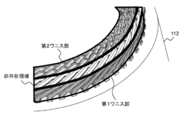
[固定子に塗布されたワニス] 図6、図7は、本実施例のワニスが塗布された固定子112の斜視図であり、図8は、本実施例のワニスが塗布された固定子112のコイルエンド110aを側方から見た図である。
[Varnish applied to the stator] FIGS. 6 and 7 are perspective views of the stator 112 coated with the varnish of the present embodiment, and FIG. 8 is the stator 112 coated with the varnish of the present embodiment. It is the figure which looked at the coil end 110a of the above from the side.
図6に示すように、固定子112に実装される固定子コイル110は、ワニスによって固定子鉄心111に固定される。固定子コイル110の固定子鉄心111の端面から突出した部分は、固定子コイル110の固定子鉄心111に近い部分でワニスが付着している第1ワニス部と、第1ワニス部よりも上部にワニスが付着している第2ワニス部と、第1ワニス部と第2ワニス部との間でワニスが付着していない非存在領域とが設けられている。
As shown in FIG. 6, the stator coil 110 mounted on the stator 112 is fixed to the stator core 111 by a varnish. The portion of the stator coil 110 that protrudes from the end face of the stator core 111 is a portion of the stator coil 110 that is close to the stator core 111 and has a varnish attached to the first varnish portion and above the first varnish portion. A second varnish portion to which the varnish is attached and a non-existent region to which the varnish is not attached are provided between the first varnish portion and the second varnish portion.
前述したように、固定子鉄心111に設けられた付着禁止エリアにワニスが付着すると、不良品となるが、図示した固定子112では、最外周コイルのワニスのコイル表面上での移動距離が短くなり、ワニスの垂れを防止し、不良品の発生を抑制できる。
As described above, if the varnish adheres to the adhesion prohibition area provided on the stator core 111, it becomes a defective product. However, in the illustrated stator 112, the moving distance of the varnish of the outermost coil on the coil surface is short. Therefore, it is possible to prevent the varnish from dripping and suppress the occurrence of defective products.
また、図6、図7、図8に示すように、ワニスが付着していない非存在領域は、第1屈曲部110eと第2屈曲部110fの間に形成される。頂点部110dに滴下されたワニスは固定子コイル110の第1屈曲部110eで滞留し、滞留したワニスが第1屈曲部110eから垂れて、固定子鉄心111に付着することがある。また、第2屈曲部110fは固定子鉄心111に近く、固定子コイル110がスロット200に収容されるように第2屈曲部110fで延伸方向を変えるため、第2屈曲部110fより固定子鉄心111側では周方向に隣接する固定子コイル110の間の隙間が大きくなり空間が生じる。そのため、第2屈曲部110fよりも固定子鉄心111側にワニスを滴下すると、滴下されたワニスが固定子コイル110の間の空間に落下して、固定子鉄心111の付着禁止エリアに付着して、不良品となる。このため、第2屈曲部110fより下側はワニス滴下位置として適切ではない。このため、固定子コイル110の第1屈曲部110eと第2屈曲部110fの間に第1ワニス部の下端と第2ワニス部の上端を設けることによって、固定子コイル110へのワニスの滞留を抑制でき、固定子コイル110から垂れたワニスが固定子鉄心111へ付着するリスクを低減できる。
Further, as shown in FIGS. 6, 7, and 8, the non-existent region to which the varnish is not attached is formed between the first bent portion 110e and the second bent portion 110f. The varnish dropped on the apex portion 110d may stay at the first bent portion 110e of the stator coil 110, and the retained varnish may hang down from the first bent portion 110e and adhere to the stator core 111. Further, since the second bent portion 110f is close to the stator core 111 and the stretching direction is changed by the second bent portion 110f so that the stator coil 110 is accommodated in the slot 200, the stator core 111 is more than the second bent portion 110f. On the side, the gap between the stator coils 110 adjacent to each other in the circumferential direction becomes large, and a space is created. Therefore, when the varnish is dropped on the stator core 111 side of the second bent portion 110f, the dropped varnish falls into the space between the stator coils 110 and adheres to the adhesion prohibition area of the stator core 111. , It becomes a defective product. Therefore, the portion below the second bent portion 110f is not suitable as the varnish dropping position. Therefore, by providing the lower end of the first varnish portion and the upper end of the second varnish portion between the first bent portion 110e and the second bent portion 110f of the stator coil 110, the varnish stays in the stator coil 110. It can be suppressed, and the risk of the varnish hanging from the stator coil 110 adhering to the stator core 111 can be reduced.
また、第1ワニス部の上端部が第1屈曲部110eと第2屈曲部110fの間に設けられるので、固定子コイル110を伝って流れるワニスが垂れて固定子鉄心111の端部へワニスが付着するのを抑制できる。第1ワニス工程では、第1屈曲部110eより固定子鉄心111に近く(図において下側で)、第2屈曲部110fより頂点部110dに近い(図において上側の)位置、すなわち、第1屈曲部110eと第2屈曲部110fの間にワニスを塗布する。このため、第1屈曲部110eと第2屈曲部110fの間に第1ワニス部の上端部が設けられ、垂れたワニスの固定子鉄心111の端部への付着を抑制できる。
Further, since the upper end of the first varnish portion is provided between the first bent portion 110e and the second bent portion 110f, the varnish flowing along the stator coil 110 hangs down and the varnish reaches the end of the stator core 111. Adhesion can be suppressed. In the first varnish step, the position closer to the stator core 111 than the first bent portion 110e (lower side in the figure) and closer to the apex 110d than the second bent portion 110f (upper side in the figure), that is, the first bending. Varnish is applied between the portion 110e and the second bent portion 110f. Therefore, the upper end portion of the first varnish portion is provided between the first bent portion 110e and the second bent portion 110f, and the adhesion of the hanging varnish to the end portion of the stator core 111 can be suppressed.
また、図8に示すように、第1ワニス部の上端部は、固定子112を軸と垂直な方向から見て、隣接する固定子コイル110が平行に重なって配置される平行重なり部110gに上端が配置されるように、第1ワニス部が形成される。この平行重なり部110gでは、固定子コイル110が隙間をあけて平行に重なって配置されるとよい。第1ワニス工程において、ワニスは回転する固定子鉄心111のコイル上に滴下する。このとき、第1屈曲部110eで滞留したワニスが垂れるので、ワニス滴下位置は第1屈曲部110eより固定子鉄心111に近い位置としている。また、隣りあう固定子コイル110同士が離れていると、滴下したワニスがその隙間に落下して、付着禁止エリアに付着することがある。このため、第1ワニス工程では、第1屈曲部110eと第2屈曲部110fの間において、隣り合うコイルが平行な隙間を形成している平行重なり部110gにワニスを滴下することで、固定子コイル110を伝って流れるワニスが垂れて固定子鉄心111への付着を防止する。
Further, as shown in FIG. 8, the upper end portion of the first varnish portion is a parallel overlapping portion 110 g in which the stator 112 is viewed from the direction perpendicular to the axis and the adjacent stator coils 110 are arranged in parallel. The first varnish portion is formed so that the upper end is arranged. In the parallel overlapping portion 110g, the stator coils 110 may be arranged so as to overlap in parallel with a gap. In the first varnish step, the varnish is dropped onto the coil of the rotating stator core 111. At this time, since the varnish accumulated in the first bent portion 110e hangs down, the varnish dropping position is set to a position closer to the stator core 111 than the first bent portion 110e. Further, if the stator coils 110 that are adjacent to each other are separated from each other, the dropped varnish may fall into the gap and adhere to the adhesion prohibited area. Therefore, in the first varnish step, the stator is dropped by dropping the varnish on the parallel overlapping portion 110 g in which the adjacent coils form a parallel gap between the first bent portion 110e and the second bent portion 110f. The varnish flowing along the coil 110 hangs down to prevent adhesion to the stator core 111.
なお、本発明は前述した実施例に限定されるものではなく、添付した特許請求の範囲の趣旨内における様々な変形例及び同等の構成が含まれる。例えば、前述した実施例は本発明を分かりやすく説明するために詳細に説明したものであり、必ずしも説明した全ての構成を備えるものに本発明は限定されない。また、ある実施例の構成の一部を他の実施例の構成に置き換えてもよい。また、ある実施例の構成に他の実施例の構成を加えてもよい。
また、各実施例の構成の一部について、他の構成の追加・削除・置換をしてもよい。 The present invention is not limited to the above-described embodiment, and includes various modifications and equivalent configurations within the scope of the appended claims. For example, the above-described examples have been described in detail in order to explain the present invention in an easy-to-understand manner, and the present invention is not necessarily limited to those having all the described configurations. Further, a part of the configuration of one embodiment may be replaced with the configuration of another embodiment. Further, the configuration of another embodiment may be added to the configuration of one embodiment.
In addition, other configurations may be added / deleted / replaced with respect to a part of the configurations of each embodiment.
10A、10B 軸受
100 回転電機
110 固定子コイル
110a、110b コイルエンド
110c 直線導体部
110d 頂点部
110e 第1屈曲部
110f 第2屈曲部
110g 平行重なり部
111 固定子鉄心
112 固定子
120 回転子
121 回転子鉄心
130 ハウジング
140 空隙
150 永久磁石
151 磁気的空隙
160 当て板
170 シャフト
180 エンドブラケット
190 レゾルバ
200 スロット
300 絶縁紙
500 電磁鋼板 10A,10B Bearing 100 Rotator coil 110a, 110b Coil end 110c Straight conductor part 110d Top part 110e First bending part 110f Second bending part 110g Parallel overlapping part 111 Stator Iron core 112 Stator 120 Rotor 121 Rotor Iron core 130 Housing 140 Void 150 Permanent magnet 151 Magnetic void 160 Back plate 170 Shaft 180 End bracket 190 Resolver 200 Slot 300 Insulating paper 500 Electromagnetic steel plate
100 回転電機
110 固定子コイル
110a、110b コイルエンド
110c 直線導体部
110d 頂点部
110e 第1屈曲部
110f 第2屈曲部
110g 平行重なり部
111 固定子鉄心
112 固定子
120 回転子
121 回転子鉄心
130 ハウジング
140 空隙
150 永久磁石
151 磁気的空隙
160 当て板
170 シャフト
180 エンドブラケット
190 レゾルバ
200 スロット
300 絶縁紙
500 電磁鋼板 10A,
Claims (12)
- 固定子コアにコイルが巻回される回転電機の固定子の製造方法であって、
前記コイルが前記固定子コアから突出しているコイルエンド部のうち、最外周又は最内周に配置され、前記固定子コアに近接した位置のコイルにワニスを滴下して第1ワニス部を形成する第1ワニス工程と、
前記第1ワニス工程より前記固定子コアから遠い位置にワニスを滴下して、前記第1ワニス部と第2ワニス部の間にワニスが塗布されていない非存在領域を設けるように、第2ワニス部を形成する第2ワニス工程と、を備える回転電機の固定子の製造方法。 It is a method of manufacturing a stator of a rotary electric machine in which a coil is wound around a stator core.
The coil is arranged on the outermost or innermost circumference of the coil end portion protruding from the stator core, and a varnish is dropped onto the coil at a position close to the stator core to form a first varnish portion. The first varnish process and
The second varnish is dropped from the first varnish step to a position farther from the stator core so as to provide a non-existing region where the varnish is not applied between the first varnish portion and the second varnish portion. A method for manufacturing a stator of a rotating electric machine, comprising a second varnishing step of forming a portion. - 請求項1に記載の回転電機の固定子の製造方法であって、
前記第2ワニス工程は、前記第1ワニス工程の後に実施される回転電機の固定子の製造方法。 The method for manufacturing a stator of a rotary electric machine according to claim 1.
The second varnish step is a method for manufacturing a stator of a rotary electric machine, which is carried out after the first varnish step. - 請求項1に記載の回転電機の固定子の製造方法であって、
前記第1ワニス工程におけるワニスの滴下方向と前記固定子の軸がなす角度は、前記第2ワニス工程におけるワニスの滴下方向と前記固定子の軸がなす角度より大きい回転電機の固定子の製造方法。 The method for manufacturing a stator of a rotary electric machine according to claim 1.
A method for manufacturing a stator of a rotary electric machine, in which the angle formed by the dropping direction of the varnish and the shaft of the stator in the first varnish step is larger than the angle formed by the dropping direction of the varnish and the shaft of the stator in the second varnish step. .. - 請求項1に記載の回転電機の固定子の製造方法であって、
前記コイルエンド部のうち前記第1ワニス部が設けられていない最外周又は最内周に配置されたコイルの、前記第2ワニス部より前記固定子コアに近接した位置にワニスを滴下して第3ワニス部を形成する第3ワニス工程を備える回転電機の固定子の製造方法。 The method for manufacturing a stator of a rotary electric machine according to claim 1.
A varnish is dropped from the second varnish portion to a position closer to the stator core of the coil arranged on the outermost or innermost circumference of the coil end portion where the first varnish portion is not provided. 3 A method for manufacturing a stator of a rotary electric machine, which comprises a third varnish step for forming a varnish portion. - 請求項1に記載の回転電機の固定子の製造方法であって、
前記コイルは、回転軸方向に屈曲する頂点部と、前記頂点部に近く、前記コイルが斜めに延伸する部分の直上に位置する第1屈曲部と、前記固定子コアから突出した後に前記コイルが斜めに延伸する部分の直下に位置する第2屈曲部と、を有し、
前記第1ワニス工程では、前記第1屈曲部と前記第2屈曲部との間に前記第1ワニス部の上端が設けられるように、ワニスを滴下する回転電機の固定子の製造方法。 The method for manufacturing a stator of a rotary electric machine according to claim 1.
The coil has an apex portion that bends in the direction of the rotation axis, a first bent portion that is close to the apex portion and is located directly above a portion where the coil extends diagonally, and the coil that protrudes from the stator core. It has a second bent portion located directly below the portion extending diagonally, and has.
In the first varnish step, a method for manufacturing a stator of a rotary electric machine for dropping varnish so that the upper end of the first varnish portion is provided between the first bent portion and the second bent portion. - 請求項5に記載の回転電機の固定子の製造方法であって、
前記第1ワニス工程では、軸方向と垂直な方向から見た場合に隣接する前記コイルが平行に重なって配置される位置に、前記第1ワニス部の上端が位置するように、ワニスを滴下する回転電機の固定子の製造方法。 The method for manufacturing a stator of a rotary electric machine according to claim 5.
In the first varnish step, the varnish is dropped so that the upper end of the first varnish portion is located at a position where the adjacent coils are arranged so as to overlap in parallel when viewed from a direction perpendicular to the axial direction. A method for manufacturing a stator for a rotary electric machine. - 回転電機の固定子であって、
複数のスロットが形成される固定子コアと、
径方向に並べて配置され、前記スロットに収納されるコイルと、を備え、
前記コイルは、
前記スロットから突出したコイルエンド部のうち、最外周又は最内周に配置されたコイルの前記固定子コアに近接した位置にワニスを滴下して形成される第1ワニス部と、
前記固定子コアから遠い位置にワニスを滴下して形成される第2ワニス部と、
前記第1ワニス部と前記第2ワニス部の間にワニスが塗布されていない非存在領域と、を有する回転電機の固定子。 It is a stator of a rotary electric machine,
With a stator core in which multiple slots are formed,
A coil that is arranged side by side in the radial direction and is housed in the slot is provided.
The coil is
A first varnish portion formed by dropping a varnish at a position close to the stator core of a coil arranged on the outermost circumference or the innermost circumference of the coil end portion protruding from the slot.
A second varnish portion formed by dropping a varnish at a position far from the stator core, and
A stator of a rotary electric machine having a non-existing region where no varnish is applied between the first varnish portion and the second varnish portion. - 請求項7に記載の回転電機の固定子であって、
前記コイルは、回転軸方向に屈曲する頂点部と、前記頂点部に近く、前記コイルが斜めに延伸する部分の直上に位置する第1屈曲部と、前記固定子コアから突出した後に前記コイルが斜めに延伸する部分の直下に位置する第2屈曲部と、を有し、
前記第1屈曲部は、前記非存在領域内に設けられる回転電機の固定子。 The stator of the rotary electric machine according to claim 7.
The coil has an apex portion that bends in the direction of the rotation axis, a first bent portion that is close to the apex portion and is located directly above a portion where the coil extends diagonally, and the coil that protrudes from the stator core. It has a second bent portion located directly below the portion extending diagonally, and has.
The first bent portion is a stator of a rotary electric machine provided in the non-existing region. - 請求項7に記載の回転電機の固定子であって、
前記コイルは、前記コイルエンド部のうち前記第1ワニス部が設けられていない最外周又は最内周に配置されたコイルの、前記第2ワニス部より前記固定子コアに近接した位置にワニスを滴下して形成される第3ワニス部を有する回転電機の固定子。 The stator of the rotary electric machine according to claim 7.
The coil has a varnish at a position closer to the stator core than the second varnish portion of the coil arranged on the outermost or innermost circumference of the coil end portion where the first varnish portion is not provided. A stator of a rotary electric machine having a third varnish portion formed by dropping. - 請求項7に記載の回転電機の固定子であって、
前記コイルは、回転軸方向に屈曲する頂点部と、前記頂点部に近く、前記コイルが斜めに延伸する部分の直上に位置する第1屈曲部と、前記固定子コアから突出した後に前記コイルが斜めに延伸する部分の直下に位置する第2屈曲部と、を有し、
前記第1ワニス部の上端が前記第1屈曲部と前記第2屈曲部との間に位置する回転電機の固定子。 The stator of the rotary electric machine according to claim 7.
The coil has an apex portion that bends in the direction of the rotation axis, a first bent portion that is close to the apex portion and is located directly above a portion where the coil extends diagonally, and the coil that protrudes from the stator core. It has a second bent portion located directly below the portion extending diagonally, and has.
A stator of a rotary electric machine in which the upper end of the first varnish portion is located between the first bent portion and the second bent portion. - 請求項7に記載の回転電機の固定子であって、
前記第1ワニス部の上端は、軸方向と垂直な方向から見た場合に、隣接する前記コイルが平行に重なって配置される回転電機の固定子。 The stator of the rotary electric machine according to claim 7.
The upper end of the first varnish portion is a stator of a rotary electric machine in which adjacent coils are arranged so as to overlap in parallel when viewed from a direction perpendicular to the axial direction. - 請求項7から11のいずれか一つに記載の固定子を有する回転電機。 A rotary electric machine having the stator according to any one of claims 7 to 11.
Priority Applications (3)
| Application Number | Priority Date | Filing Date | Title |
|---|---|---|---|
| JP2022509306A JP7308351B2 (en) | 2020-03-25 | 2021-01-15 | Method for manufacturing stator for rotating electrical machine, stator for rotating electrical machine, and rotating electrical machine |
| US17/798,777 US20230109194A1 (en) | 2020-03-25 | 2021-01-15 | Method for manufacturing stator of rotating electric machine, stator of rotating electric machine, and rotating electric machine |
| CN202180014263.6A CN115088166A (en) | 2020-03-25 | 2021-01-15 | Method for manufacturing stator of rotating electrical machine, and rotating electrical machine |
Applications Claiming Priority (2)
| Application Number | Priority Date | Filing Date | Title |
|---|---|---|---|
| JP2020-055135 | 2020-03-25 | ||
| JP2020055135 | 2020-03-25 |
Publications (1)
| Publication Number | Publication Date |
|---|---|
| WO2021192531A1 true WO2021192531A1 (en) | 2021-09-30 |
Family
ID=77891365
Family Applications (1)
| Application Number | Title | Priority Date | Filing Date |
|---|---|---|---|
| PCT/JP2021/001187 WO2021192531A1 (en) | 2020-03-25 | 2021-01-15 | Method for manufacturing stator for dynamo-electric machine, stator for dynamo-electric machine, and dynamo-electric machine |
Country Status (4)
| Country | Link |
|---|---|
| US (1) | US20230109194A1 (en) |
| JP (1) | JP7308351B2 (en) |
| CN (1) | CN115088166A (en) |
| WO (1) | WO2021192531A1 (en) |
Citations (3)
| Publication number | Priority date | Publication date | Assignee | Title |
|---|---|---|---|---|
| WO2005027320A1 (en) * | 2003-09-10 | 2005-03-24 | Aisin Aw Co., Ltd. | Device and method for manufacture of rotating electric machine |
| JP2010178554A (en) * | 2009-01-30 | 2010-08-12 | Nissan Motor Co Ltd | Method of impregnating stator core with varnish |
| JP2016116260A (en) * | 2014-12-11 | 2016-06-23 | トヨタ自動車株式会社 | Method for manufacturing stator comprising stator core and coil |
Family Cites Families (2)
| Publication number | Priority date | Publication date | Assignee | Title |
|---|---|---|---|---|
| JP5962607B2 (en) * | 2013-07-23 | 2016-08-03 | トヨタ自動車株式会社 | Rotating electrical machine stator and manufacturing method thereof |
| JP2020010558A (en) * | 2018-07-11 | 2020-01-16 | アイシン・エィ・ダブリュ株式会社 | Manufacturing method of stator |
-
2021
- 2021-01-15 JP JP2022509306A patent/JP7308351B2/en active Active
- 2021-01-15 WO PCT/JP2021/001187 patent/WO2021192531A1/en active Application Filing
- 2021-01-15 CN CN202180014263.6A patent/CN115088166A/en active Pending
- 2021-01-15 US US17/798,777 patent/US20230109194A1/en active Pending
Patent Citations (3)
| Publication number | Priority date | Publication date | Assignee | Title |
|---|---|---|---|---|
| WO2005027320A1 (en) * | 2003-09-10 | 2005-03-24 | Aisin Aw Co., Ltd. | Device and method for manufacture of rotating electric machine |
| JP2010178554A (en) * | 2009-01-30 | 2010-08-12 | Nissan Motor Co Ltd | Method of impregnating stator core with varnish |
| JP2016116260A (en) * | 2014-12-11 | 2016-06-23 | トヨタ自動車株式会社 | Method for manufacturing stator comprising stator core and coil |
Also Published As
| Publication number | Publication date |
|---|---|
| CN115088166A (en) | 2022-09-20 |
| JP7308351B2 (en) | 2023-07-13 |
| JPWO2021192531A1 (en) | 2021-09-30 |
| US20230109194A1 (en) | 2023-04-06 |
Similar Documents
| Publication | Publication Date | Title |
|---|---|---|
| JP6122148B2 (en) | Rotating electric machine | |
| US7683516B2 (en) | Production method for rotating electric machine and stator coils, and electric power steering motor | |
| JP3651491B2 (en) | Motor coil terminal fixing method | |
| KR101677074B1 (en) | Electric machine | |
| JP6616362B2 (en) | Brushless motor and stator winding method | |
| WO2017038310A1 (en) | Stator coil, stator equipped with same, and rotary electric machine equipped with this stator | |
| JP2002272046A (en) | Stator of rotating electric machine, and manufacturing method of the same | |
| JP2003032939A (en) | Electric motor | |
| CN103795194B (en) | The manufacturing method for stators of electric rotating machine | |
| CN108028564A (en) | The manufacture method of rotor, the electric rotating machine for being equipped with rotor and rotor | |
| EP3840186A1 (en) | Rotating electric machine | |
| JP7061194B2 (en) | Stator of rotary electric machine and its manufacturing method | |
| EP3790170A1 (en) | Rotating machine and insulator | |
| WO2021192531A1 (en) | Method for manufacturing stator for dynamo-electric machine, stator for dynamo-electric machine, and dynamo-electric machine | |
| JPH1175334A (en) | Stator of ac generator for vehicle and dismantling method therefor | |
| JP6279122B1 (en) | Rotating electric machine | |
| JPH07135745A (en) | Core of motor | |
| US20230045248A1 (en) | Stator of rotating electrical machine, insulating member for rotating electrical machine, and rotating electrical machine | |
| JP2005176463A (en) | Motor | |
| US20220344981A1 (en) | Laminated core of electric machine, electric machine, method for manufacturing laminated core of electric machine, and method for manufacturing electric machine | |
| JP2023104065A (en) | busbar unit | |
| CN111953114A (en) | Stator, motor, and air blower | |
| JP2020005356A (en) | Rotary electric machine stator and rotary electric machine | |
| JP2014131429A (en) | Wire connection structure, rotary machine, electric vehicle, and wire connecting method |
Legal Events
| Date | Code | Title | Description |
|---|---|---|---|
| 121 | Ep: the epo has been informed by wipo that ep was designated in this application |
Ref document number: 21774394 Country of ref document: EP Kind code of ref document: A1 |
|
| ENP | Entry into the national phase |
Ref document number: 2022509306 Country of ref document: JP Kind code of ref document: A |
|
| NENP | Non-entry into the national phase |
Ref country code: DE |
|
| 122 | Ep: pct application non-entry in european phase |
Ref document number: 21774394 Country of ref document: EP Kind code of ref document: A1 |