WO2021187085A1 - 制御装置 - Google Patents
制御装置 Download PDFInfo
- Publication number
- WO2021187085A1 WO2021187085A1 PCT/JP2021/007883 JP2021007883W WO2021187085A1 WO 2021187085 A1 WO2021187085 A1 WO 2021187085A1 JP 2021007883 W JP2021007883 W JP 2021007883W WO 2021187085 A1 WO2021187085 A1 WO 2021187085A1
- Authority
- WO
- WIPO (PCT)
- Prior art keywords
- amount
- excess
- reforming catalyst
- control device
- water vapor
- Prior art date
- Legal status (The legal status is an assumption and is not a legal conclusion. Google has not performed a legal analysis and makes no representation as to the accuracy of the status listed.)
- Ceased
Links
Images

Classifications
-
- C—CHEMISTRY; METALLURGY
- C01—INORGANIC CHEMISTRY
- C01B—NON-METALLIC ELEMENTS; COMPOUNDS THEREOF; METALLOIDS OR COMPOUNDS THEREOF NOT COVERED BY SUBCLASS C01C
- C01B3/00—Hydrogen; Gaseous mixtures containing hydrogen; Separation of hydrogen from mixtures containing it; Purification of hydrogen; Reversible storage of hydrogen
- C01B3/02—Production of hydrogen; Production of gaseous mixtures containing hydrogen
- C01B3/32—Production of hydrogen; Production of gaseous mixtures containing hydrogen by reaction of gaseous or liquid organic compounds with gasifying agents, e.g. water, carbon dioxide or air
- C01B3/34—Production of hydrogen; Production of gaseous mixtures containing hydrogen by reaction of gaseous or liquid organic compounds with gasifying agents, e.g. water, carbon dioxide or air by reaction of hydrocarbons with gasifying agents
- C01B3/38—Production of hydrogen; Production of gaseous mixtures containing hydrogen by reaction of gaseous or liquid organic compounds with gasifying agents, e.g. water, carbon dioxide or air by reaction of hydrocarbons with gasifying agents using catalysts
-
- F—MECHANICAL ENGINEERING; LIGHTING; HEATING; WEAPONS; BLASTING
- F02—COMBUSTION ENGINES; HOT-GAS OR COMBUSTION-PRODUCT ENGINE PLANTS
- F02B—INTERNAL-COMBUSTION PISTON ENGINES; COMBUSTION ENGINES IN GENERAL
- F02B51/00—Other methods of operating engines involving pretreating of, or adding substances to, combustion air, fuel, or fuel-air mixture of the engines
- F02B51/02—Other methods of operating engines involving pretreating of, or adding substances to, combustion air, fuel, or fuel-air mixture of the engines involving catalysts
-
- F—MECHANICAL ENGINEERING; LIGHTING; HEATING; WEAPONS; BLASTING
- F02—COMBUSTION ENGINES; HOT-GAS OR COMBUSTION-PRODUCT ENGINE PLANTS
- F02D—CONTROLLING COMBUSTION ENGINES
- F02D19/00—Controlling engines characterised by their use of non-liquid fuels, pluralities of fuels, or non-fuel substances added to the combustible mixtures
- F02D19/02—Controlling engines characterised by their use of non-liquid fuels, pluralities of fuels, or non-fuel substances added to the combustible mixtures peculiar to engines working with gaseous fuels
-
- F—MECHANICAL ENGINEERING; LIGHTING; HEATING; WEAPONS; BLASTING
- F02—COMBUSTION ENGINES; HOT-GAS OR COMBUSTION-PRODUCT ENGINE PLANTS
- F02D—CONTROLLING COMBUSTION ENGINES
- F02D19/00—Controlling engines characterised by their use of non-liquid fuels, pluralities of fuels, or non-fuel substances added to the combustible mixtures
- F02D19/06—Controlling engines characterised by their use of non-liquid fuels, pluralities of fuels, or non-fuel substances added to the combustible mixtures peculiar to engines working with pluralities of fuels, e.g. alternatively with light and heavy fuel oil, other than engines indifferent to the fuel consumed
- F02D19/08—Controlling engines characterised by their use of non-liquid fuels, pluralities of fuels, or non-fuel substances added to the combustible mixtures peculiar to engines working with pluralities of fuels, e.g. alternatively with light and heavy fuel oil, other than engines indifferent to the fuel consumed simultaneously using pluralities of fuels
-
- F—MECHANICAL ENGINEERING; LIGHTING; HEATING; WEAPONS; BLASTING
- F02—COMBUSTION ENGINES; HOT-GAS OR COMBUSTION-PRODUCT ENGINE PLANTS
- F02D—CONTROLLING COMBUSTION ENGINES
- F02D21/00—Controlling engines characterised by their being supplied with non-airborne oxygen or other non-fuel gas
- F02D21/06—Controlling engines characterised by their being supplied with non-airborne oxygen or other non-fuel gas peculiar to engines having other non-fuel gas added to combustion air
- F02D21/08—Controlling engines characterised by their being supplied with non-airborne oxygen or other non-fuel gas peculiar to engines having other non-fuel gas added to combustion air the other gas being the exhaust gas of engine
-
- F—MECHANICAL ENGINEERING; LIGHTING; HEATING; WEAPONS; BLASTING
- F02—COMBUSTION ENGINES; HOT-GAS OR COMBUSTION-PRODUCT ENGINE PLANTS
- F02D—CONTROLLING COMBUSTION ENGINES
- F02D45/00—Electrical control not provided for in groups F02D41/00 - F02D43/00
-
- F—MECHANICAL ENGINEERING; LIGHTING; HEATING; WEAPONS; BLASTING
- F02—COMBUSTION ENGINES; HOT-GAS OR COMBUSTION-PRODUCT ENGINE PLANTS
- F02M—SUPPLYING COMBUSTION ENGINES IN GENERAL WITH COMBUSTIBLE MIXTURES OR CONSTITUENTS THEREOF
- F02M26/00—Engine-pertinent apparatus for adding exhaust gases to combustion-air, main fuel or fuel-air mixture, e.g. by exhaust gas recirculation [EGR] systems
- F02M26/02—EGR systems specially adapted for supercharged engines
- F02M26/04—EGR systems specially adapted for supercharged engines with a single turbocharger
- F02M26/05—High pressure loops, i.e. wherein recirculated exhaust gas is taken out from the exhaust system upstream of the turbine and reintroduced into the intake system downstream of the compressor
-
- F—MECHANICAL ENGINEERING; LIGHTING; HEATING; WEAPONS; BLASTING
- F02—COMBUSTION ENGINES; HOT-GAS OR COMBUSTION-PRODUCT ENGINE PLANTS
- F02M—SUPPLYING COMBUSTION ENGINES IN GENERAL WITH COMBUSTIBLE MIXTURES OR CONSTITUENTS THEREOF
- F02M26/00—Engine-pertinent apparatus for adding exhaust gases to combustion-air, main fuel or fuel-air mixture, e.g. by exhaust gas recirculation [EGR] systems
- F02M26/13—Arrangement or layout of EGR passages, e.g. in relation to specific engine parts or for incorporation of accessories
- F02M26/36—Arrangement or layout of EGR passages, e.g. in relation to specific engine parts or for incorporation of accessories with means for adding fluids other than exhaust gas to the recirculation passage; with reformers
-
- F—MECHANICAL ENGINEERING; LIGHTING; HEATING; WEAPONS; BLASTING
- F02—COMBUSTION ENGINES; HOT-GAS OR COMBUSTION-PRODUCT ENGINE PLANTS
- F02M—SUPPLYING COMBUSTION ENGINES IN GENERAL WITH COMBUSTIBLE MIXTURES OR CONSTITUENTS THEREOF
- F02M27/00—Apparatus for treating combustion-air, fuel, or fuel-air mixture, by catalysts, electric means, magnetism, rays, sound waves, or the like
- F02M27/02—Apparatus for treating combustion-air, fuel, or fuel-air mixture, by catalysts, electric means, magnetism, rays, sound waves, or the like by catalysts
-
- Y—GENERAL TAGGING OF NEW TECHNOLOGICAL DEVELOPMENTS; GENERAL TAGGING OF CROSS-SECTIONAL TECHNOLOGIES SPANNING OVER SEVERAL SECTIONS OF THE IPC; TECHNICAL SUBJECTS COVERED BY FORMER USPC CROSS-REFERENCE ART COLLECTIONS [XRACs] AND DIGESTS
- Y02—TECHNOLOGIES OR APPLICATIONS FOR MITIGATION OR ADAPTATION AGAINST CLIMATE CHANGE
- Y02T—CLIMATE CHANGE MITIGATION TECHNOLOGIES RELATED TO TRANSPORTATION
- Y02T10/00—Road transport of goods or passengers
- Y02T10/10—Internal combustion engine [ICE] based vehicles
- Y02T10/12—Improving ICE efficiencies
-
- Y—GENERAL TAGGING OF NEW TECHNOLOGICAL DEVELOPMENTS; GENERAL TAGGING OF CROSS-SECTIONAL TECHNOLOGIES SPANNING OVER SEVERAL SECTIONS OF THE IPC; TECHNICAL SUBJECTS COVERED BY FORMER USPC CROSS-REFERENCE ART COLLECTIONS [XRACs] AND DIGESTS
- Y02—TECHNOLOGIES OR APPLICATIONS FOR MITIGATION OR ADAPTATION AGAINST CLIMATE CHANGE
- Y02T—CLIMATE CHANGE MITIGATION TECHNOLOGIES RELATED TO TRANSPORTATION
- Y02T10/00—Road transport of goods or passengers
- Y02T10/10—Internal combustion engine [ICE] based vehicles
- Y02T10/30—Use of alternative fuels, e.g. biofuels
Definitions
- This disclosure relates to a control device for a vehicle.
- the amount of reformed gas produced is calculated based on the pressure difference between the pressure when the fuel is reformed and the pressure when the fuel is not reformed. It describes what to do. According to such a method, it is possible to detect a decrease in the amount of reformed gas produced due to deterioration of the reforming catalyst without using a special sensor such as a hydrogen sensor.
- the amount of reformed gas produced in the reforming catalyst changes according to the amount of water vapor reaching the reforming catalyst.
- the amount of water vapor varies depending on various factors such as the amount of water contained in the fuel and the humidity in the air existing around the vehicle.
- An object of the present disclosure is to provide a control device capable of sufficiently securing the amount of reformed gas produced.
- the control device is a control device for vehicles.
- the vehicle is provided with a reforming catalyst for generating hydrogen by a fuel reforming reaction at a position in the middle of an EGR flow path for recirculating exhaust gas toward an internal combustion engine.
- This control device determines the flow rate of the exhaust gas supplied from the EGR flow path to the internal combustion engine based on the judgment result of the excess / deficiency determination unit that determines the excess / deficiency of the amount of steam reaching the reforming catalyst and the excess / deficiency determination unit. It is provided with an adjustment unit for adjustment.
- the flow rate of the exhaust gas supplied from the EGR flow path to the internal combustion engine is adjusted based on the excess or deficiency of the amount of water vapor reaching the reforming catalyst, and as a result, it is modified together with the exhaust gas.
- the amount of water vapor reaching the quality catalyst can be adjusted.
- the amount of steam that reaches the reforming catalyst can be maintained at an appropriate amount, and the amount of reformed gas produced can be sufficiently secured.
- a control device capable of sufficiently securing the amount of reformed gas produced is provided.
- FIG. 1 is a diagram schematically showing a configuration of a control device according to the first embodiment and a configuration of a vehicle on which the control device is mounted.
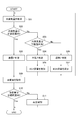
- FIG. 2 is a flowchart showing a flow of processing executed by the control device according to the first embodiment.
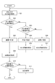
- FIG. 3 is a flowchart showing a flow of processing executed by the control device according to the second embodiment.
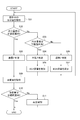
- FIG. 4 is a flowchart showing a flow of processing executed by the control device according to the second embodiment.
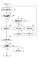
- FIG. 5 is a flowchart showing a flow of processing executed by the control device according to the fourth embodiment.
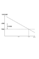
- FIG. 6 is a diagram showing the relationship between the S / C of the gas reaching the reforming catalyst and the catalyst bed temperature.
- the control device 10 is mounted on the vehicle MV and is configured as a device for performing various controls on the vehicle MV. Prior to the description of the control device 10, the configuration of the vehicle MV will be described first.
- the vehicle MV includes an internal combustion engine EG, an intake pipe 100, an exhaust pipe 200, and an EGR pipe 300.
- the internal combustion engine EG is a so-called engine.
- the internal combustion engine EG generates the driving force required for traveling the vehicle MV by burning the fuel inside the cylinder.
- the internal combustion engine EG has a plurality of cylinders, but only one of them is shown in FIG.
- Each cylinder of the internal combustion engine EG is provided with an injector IJ1 for injecting and supplying fuel.
- the injector IJ1 is an on-off valve that opens and closes in response to an external signal. The opening / closing operation of the injector IJ1 is controlled by the control device 10.
- the vehicle MV is equipped with a fuel tank FT for storing fuel.
- the fuel tank FT is provided with a feed pump (not shown) for pressurizing and delivering fuel.
- the injector IJ1 When the injector IJ1 is opened, the fuel pressurized by the feed pump is directly injected into the cylinder of the internal combustion engine EG.
- the fuel from the injector IJ1 is directly injected into the cylinder as described above.
- the injector IJ1 may be provided in the intake pipe 100 described later, and the fuel may be injected inside the intake pipe 100. Further, both an injector for injecting fuel into the cylinder and an injector for injecting fuel into the intake pipe 100 may be provided.
- the intake pipe 100 is a pipe for supplying the air (that is, outside air) taken in from the outside of the vehicle MV to the internal combustion engine EG.
- the intake pipe 100 is provided with an air cleaner AC, a compressor 131, an intercooler IC, a throttle valve TV, and an intake manifold IM in this order from the upstream side along the air flow direction.
- the air cleaner AC is for removing foreign matter from the air with a filter.
- the air cleaner AC has a built-in temperature sensor 120 for measuring the temperature of air. A signal indicating the temperature measured by the temperature sensor 120 is input to the control device 10.
- a humidity sensor 110 for measuring the humidity of air is provided at a position upstream of the air cleaner AC, specifically, at a position near an air intake port (not shown) provided in the vehicle MV. ing.
- a signal indicating the humidity measured by the humidity sensor 110 is input to the control device 10.
- the position where the humidity sensor 110 is provided may be a position in the middle of the intake pipe 100, for example, a position between the air cleaner AC and the compressor 131. Since the humidity sensor 110 is a sensor for measuring the humidity of the air taken into the vehicle MV, that is, the amount of water in the atmosphere, it can also be called a "moisture sensor".
- the compressor 131 is a part of the turbocharger TC, which is a supercharger, and is for compressing air and sending it to the downstream side.
- the turbocharger TC has the above-mentioned compressor 131 and a turbine 132. When the turbine 132 arranged in the exhaust pipe 200 is rotated by the flow of the exhaust gas, the compressor 131 is also rotated at the same time, so that air is sent out toward the internal combustion engine EG.
- the intercooler IC is a heat exchanger for cooling the air compressed by the operation of the compressor 131 and having a high temperature by exchanging heat with the cooling water.
- the throttle valve TV is a valve for adjusting the flow rate of air supplied from the intake pipe 100 to the internal combustion engine.
- the opening degree of the throttle valve TV is adjusted by the control device 10 according to the amount of depression of the accelerator pedal (not shown) provided on the vehicle MV.
- the intake manifold IM branches the downstream portion of the intake pipe 100 into a plurality of pipes in order to connect the intake pipe 100 to each cylinder of the internal combustion engine EG.
- the exhaust pipe 200 is a pipe for guiding the exhaust gas generated by the combustion of the internal combustion engine EG to the outside of the vehicle MV and discharging it.
- the exhaust pipe 200 is provided with a turbine 132 and a purification device TWC in this order from the upstream side along the flow direction of the exhaust gas.
- Turbine 132 is a part of turbocharger TC as mentioned above.
- the turbine 132 is rotated by the flow of exhaust gas in the exhaust pipe 200, and rotates the compressor 131 of the turbocharger TC.
- the exhaust pipe 200 is provided with a bypass pipe 201 for passing the exhaust gas by bypassing the turbine 132.
- a wastegate valve WG is provided at a position in the middle of the bypass pipe 201.
- the wastegate valve WG is a valve for adjusting the flow rate of air supercharged to the internal combustion engine EG by changing the amount of exhaust gas flowing through the bypass pipe 201.
- the opening degree of the wastegate valve WG is adjusted by the control device 10.
- Purification device TWC is a device for purifying harmful substances such as nitrogen oxides and carbon monoxide contained in exhaust gas with an internal three-way catalyst.
- the EGR pipe 300 is a pipe for returning a part of the exhaust gas passing through the exhaust pipe 200 to the intake pipe 100 and supplying it to the internal combustion engine EG again.
- One end of the EGR pipe 300 is connected to a position of the exhaust pipe 200 on the upstream side of the turbine 132 along the flow direction of the exhaust gas.
- the other end of the EGR pipe 300 is connected to the intake pipe 100 at a position downstream of the throttle valve TV along the air flow direction.
- the flow path formed inside the EGR pipe corresponds to an "EGR flow path" for recirculating the exhaust gas toward the internal combustion engine EG.
- the EGR pipe 300 may be connected at a position different from the above.
- one end of the EGR pipe 300 may be connected to a position downstream of the purification device TWC, and the other end of the EGR pipe 300 may be connected to a position upstream of the compressor 131 of the turbocharger TC. .. That is, the EGR pipe 300 may be connected so as to return a part of the exhaust gas after passing through the purification device TWC to the upstream side of the compressor 131.
- the EGR pipe 300 is provided with an injector IJ2, a mixer MX, a reformer RF, an EGR cooler EC, and an EGR valve EV in this order from the upstream side along the flow direction of the exhaust gas.
- the reformer RF is for generating a reforming gas such as hydrogen at a position in the middle of the EGR pipe 300, that is, a position in the middle of the EGR flow path, and supplying this to the internal combustion engine EG together with the exhaust gas. ..
- the reforming catalyst CT is housed inside the reformer RF.
- the reformed catalyst CT is, for example, one in which a catalyst metal such as nickel is supported on a base material made of alumina or the like.
- the hydrocarbon and water supplied from the EGR pipe 300 come into contact with the reforming catalyst CT to cause a steam reforming reaction, and a reforming gas composed of hydrogen and carbon monoxide is generated.
- the steam reforming reaction is ideally represented by the following formula (1). C 7 H 14 + 7H 2 O ⁇ 14H 2 + 7CO ⁇ (1)
- the vehicle MV is provided with an injector IJ2 as a supply source of hydrocarbons.
- the injector IJ2 is an on-off valve having the same configuration as the injector IJ1 described above.
- the injector IJ2 is provided in the EGR pipe 300 at a position on the upstream side of the reformer RF along the flow direction of the exhaust gas. The opening / closing operation of the injector IJ2 is controlled by the control device 10.
- the fuel When the fuel is injected from the injector IJ2, the fuel is mixed with the exhaust gas when passing through the mixer MX arranged on the downstream side, and then supplied to the reformer RF, and the steam reforming reaction is carried out as described above. It is offered to.
- the fuel injected from the injector IJ2 is stored in the fuel tank FT in the same manner as the fuel injected from the injector IJ1.
- the water required for the steam reforming reaction is mainly generated by the combustion of fuel in the internal combustion engine EG.
- the combustion reaction by the internal combustion engine EG is represented by the following equation (2). C 7 H 14 + 10.5O 2 ⁇ 7H 2 O + 7CO 2 ⁇ (2)
- the water represented by the first item on the right side of the formula (2) is supplied to the reformer RF together with the exhaust gas through the EGR pipe 300, and is subjected to the steam reforming reaction as described above. Therefore, as the amount of combustion in the internal combustion engine EG increases, the amount of water vapor that reaches the reforming catalyst CT through the EGR pipe 300 increases accordingly.
- the steam reforming reaction is an endothermic reaction as is well known. Therefore, in order for the steam reforming reaction to occur continuously, heat must be continuously supplied to the reforming catalyst CT. Therefore, in the vehicle MV, the reformer RF is provided at a position in the middle of the exhaust pipe 200, and the reforming catalyst CT is heated by the exhaust gas passing through the exhaust pipe 200. That is, the high-temperature exhaust gas passing through the exhaust pipe 200 is used as a heat source for maintaining the steam reforming reaction.
- the vehicle MV equipped with the control device 10 is reformed to generate hydrogen by the fuel reforming reaction at a position in the middle of the EGR flow path for recirculating the exhaust gas toward the internal combustion engine EG.
- a catalyst CT is provided.
- a to h in the formula (3) represent arbitrary numerical values.
- the water shown in the second term on the left side of the formula (3) was contained not only in the water generated by the combustion reaction in the formula (2), but also in the water contained in the air passing through the intake pipe 100 and in the fuel. It is the sum of water. For example, if the humidity of the air becomes high and the amount of water reaching the reforming catalyst CT becomes too large, a part of the water does not participate in the steam reforming reaction and is discharged from the reformer RF to the downstream side. The Rukoto.
- the third term on the right side of the formula (3) indicates the water discharged in this way.
- the carbon dioxide shown in the third term on the left side of the formula (3) is the carbon dioxide generated by the combustion reaction of the formula (2) reaching the reformer RF from the internal combustion engine EG through the EGR pipe 300. .. As the amount of carbon dioxide increases, the amount of carbon dioxide emitted from the reformer RF to the downstream side also increases.
- the fourth term on the right side of the equation (3) indicates the carbon dioxide emitted in this way.
- C n H m shown in the fifth term on the right side of the formula (3) represents a hydrocarbon produced as a by-product of the steam reforming reaction.
- Such hydrocarbons are generated when the amount of water, which is a material for steam reforming, is not appropriate and becomes excessive or insufficient. Such hydrocarbons cause so-called “carbon precipitation” and deteriorate the performance of the reforming catalyst CT.
- this "appropriate amount range” means steam such that the S / C value, which is the molar ratio of carbon and steam contained in the raw material of the steam reforming reaction, is 1.0 to 1.2. It is set as a range of quantities.
- the above-mentioned upper limit value and lower limit value of S / C are merely examples.
- the control device 10 controls the amount of water vapor reaching the reforming catalyst CT to be an appropriate amount, and the specific contents thereof will be described later.
- the EGR cooler EC is a heat exchanger for cooling the exhaust gas passing through the EGR pipe 300 by heat exchange with the cooling water.
- the EGR cooler EC is provided in the EGR pipe 300 at a position downstream of the reformer RF along the flow direction of the exhaust gas.
- the EGR valve EV is a valve for adjusting the flow rate of the exhaust gas passing through the EGR pipe 300.
- the EGR valve EV is provided in the EGR pipe 300 at a position on the downstream side of the EGR cooler EC along the flow direction of the exhaust gas.
- the EGR valve EV is configured as an electric valve capable of changing its opening degree in response to an external signal.
- the opening degree of the EGR valve EV is adjusted by the control device 10.
- the position where the EGR valve EV is provided may be a position different from the above.
- the EGR valve EV may be provided in the EGR pipe 300 at a position on the upstream side of the reformer RF along the flow direction of the exhaust gas.
- the fuel tank FT is provided with a water content sensor 410.
- the water content sensor 410 is a sensor for measuring the amount of water contained in the fuel stored in the fuel tank FT.
- the signal indicating the water content measured by the water content sensor 410 is input to the control device 10.
- a temperature sensor 310 is provided in the EGR pipe 300 at a position near the connection portion with the exhaust pipe 200.
- the temperature sensor 310 is a sensor for measuring the temperature of the exhaust gas at the position.
- a signal indicating the temperature measured by the temperature sensor 310 is input to the control device 10.
- a steam sensor 320 is provided in the EGR pipe 300 at a position on the upstream side of the reformer RF and the injector IJ2 along the direction in which the exhaust gas flows.
- the water vapor sensor 320 is a sensor for measuring the amount of water vapor contained in the exhaust gas at the position.
- a signal indicating the amount of water vapor measured by the water vapor sensor 320 is input to the control device 10.
- the amount of water vapor measured by the steam sensor 320 can be referred to as "the amount of water vapor reaching the reforming catalyst CT".
- a temperature sensor 330 is provided in the EGR pipe 300 at a position near the inlet of the reformer RF.
- the temperature sensor 330 is a sensor for measuring the temperature of the exhaust gas at the position.
- a signal indicating the temperature measured by the temperature sensor 330 is input to the control device 10.
- a temperature sensor 340 is provided inside the reformer RF.
- the temperature sensor 340 is a sensor for directly measuring the temperature of the base material of the reforming catalyst CT, that is, the catalyst bed temperature of the reforming catalyst CT.
- the signal indicating the catalyst bed temperature measured by the temperature sensor 340 is input to the control device 10.
- a temperature sensor 350 is provided in the EGR pipe 300 at a position near the outlet of the reformer RF.
- the temperature sensor 350 is a sensor for measuring the temperature of the exhaust gas at the position.
- a signal indicating the temperature measured by the temperature sensor 350 is input to the control device 10.
- a hydrogen concentration sensor 360 is provided in the EGR pipe 300 at a position downstream of the EGR valve EV along the direction in which the exhaust gas flows.
- the hydrogen concentration sensor 360 is a sensor for measuring the concentration of hydrogen contained in the exhaust gas at the position.
- the signal indicating the hydrogen concentration measured by the hydrogen concentration sensor 360 is input to the control device 10.
- An A / F sensor 210 is provided at a position of the exhaust pipe 200 between the turbine 132 and the reformer RF along the direction in which the exhaust gas flows.
- the A / F sensor 210 is a sensor for measuring the air-fuel ratio of the exhaust gas at the position.
- the signal indicating the air-fuel ratio measured by the A / F sensor 210 is input to the control device 10.
- the configuration of the control device 10 will be described with reference to FIG.
- the control device 10 is a computer system having a CPU, ROM, RAM, and the like, and is configured as a device for controlling the vehicle MV.
- the control device 10 not only controls the opening degree of the EGR valve EV, which will be described later, but also controls the ignition timing in the internal combustion engine EG, and controls the fuel from the injectors IJ1 and IJ2. It also controls to adjust the injection amount.
- the control device 10 may be configured as a dedicated device for only controlling the opening degree of the EGR valve EV. In this case, the ignition timing of the internal combustion engine EG is controlled by the engine ECU separately mounted on the vehicle MV.
- the control device 10 includes an excess / deficiency determination unit 11 and an adjustment unit 12 as block elements representing its function.
- the excess / deficiency determination unit 11 is a portion that performs a process of determining excess / deficiency of the amount of water vapor reaching the reforming catalyst CT. The specific determination method will be described later.
- the adjusting unit 12 is a unit that adjusts the flow rate of the exhaust gas supplied from the EGR flow path to the internal combustion engine EG based on the determination result of the excess / deficiency determination unit 11.
- the "flow rate of exhaust gas supplied from the EGR flow path to the internal combustion engine EG" is also referred to as "EGR flow rate” below.
- the adjusting unit 12 performs a process of reducing the opening degree of the EGR valve EV so that the EGR flow rate becomes smaller. I do.
- the EGR flow rate becomes smaller, the amount of water vapor generated in the combustion reaction of the formula (2) becomes smaller, so that the amount of water vapor reaching the reforming catalyst CT decreases.
- the adjusting unit 12 increases the opening degree of the EGR valve EV so as to increase the EGR flow rate. Perform processing. As a result, when the EGR flow rate increases, the amount of water vapor generated in the combustion reaction of the formula (2) increases, so that the amount of water vapor reaching the reforming catalyst CT increases.
- the amount of water vapor reaching the reforming catalyst CT from the EGR pipe 300 is increased from the lower limit value (1.0 in the present embodiment) to the upper limit value (1 in the present embodiment) of the S / C. It is possible to put it in an appropriate amount range that fits in the range of .2).
- a process of acquiring the amount of water vapor reaching the reforming catalyst CT is performed.
- the amount of water vapor measured by the steam sensor 320 is acquired as the amount of water vapor reaching the reforming catalyst CT.
- step S02 it is determined whether or not the amount of water vapor acquired in step S01 is within a predetermined range.
- This predetermined range is the amount of water vapor such that the S / C of the gas reaching the reforming catalyst CT falls within the range from the lower limit value (1.0 in the present embodiment) to the upper limit value (1.2 in the present embodiment). It is set in advance as an appropriate amount range of. If the amount of water vapor is within the predetermined range, the process proceeds to step S06. In step S08, the excess / deficiency determination unit 11 determines that the amount of water vapor reaching the reforming catalyst CT is an appropriate amount, that is, that the amount of water vapor is not excessive or deficient. After that, the process proceeds to step S09, which will be described later.
- step S02 determines whether or not the amount of water vapor acquired in step S01 is less than the lower limit of the predetermined range. If the amount of water vapor is less than the lower limit, the process proceeds to step S04. In step S04, the excess / deficiency determination unit 11 determines that the amount of water vapor reaching the reforming catalyst CT is insufficient.
- step S05 the adjusting unit 12 performs a process of increasing the opening degree of the EGR valve EV so that the EGR flow rate increases more than before.
- the S / C is an appropriate amount in the range of the lower limit value (1.0 in the present embodiment) to the upper limit value (1.2 in the present embodiment). It will be closer to the range.
- step S03 If it is determined in step S03 that the amount of water vapor is not less than the lower limit, the process proceeds to step S06.
- the transition to step S06 means that the amount of water vapor acquired in step S01 exceeds the upper limit of the appropriate amount range. Therefore, in step S06, the excess / deficiency determination unit 11 determines that the amount of water vapor reaching the reforming catalyst CT is excessive.
- step S07 following step S06 the adjusting unit 12 performs a process of reducing the opening degree of the EGR valve EV so that the EGR flow rate is reduced more than before.
- the amount of water vapor reaching the reforming catalyst CT is reduced, and the S / C is an appropriate amount in the range of the lower limit value (1.0 in the present embodiment) to the upper limit value (1.2 in the present embodiment). It will be closer to the range.
- the EGR flow rate is adjusted by the adjusting unit 12 regardless of whether the amount of water vapor reaching the reforming catalyst CT is insufficient or excessive, and the amount of water vapor approaches the appropriate amount range. It becomes. Therefore, finally, the process proceeds to step S08, and it is determined that the amount of water vapor reaching the reforming catalyst CT is an appropriate amount.
- step S09 following step S08 a process of acquiring the reforming amount is performed.
- the value of the hydrogen concentration measured by the hydrogen concentration sensor 360 is acquired as a value indicating the reformed amount.
- step S10 it is determined whether or not the reforming amount acquired in step S09 is within a predetermined target range.
- This "target range” is the range of the reforming amount obtained when the reforming catalyst CT is not deteriorated and the amounts of hydrocarbons and steam which are the raw materials of the steam reforming reaction are appropriate. Is set in advance. In the target range, both the upper limit value and the lower limit value may be set, but only the lower limit value may be set.
- step S11 When the reforming amount is within the target range, the series of processes shown in FIG. 2 is completed. If the reforming amount is out of the target range, the process proceeds to step S11.
- step S11 reproduction control is performed.
- the "regeneration control” is a control for regenerating the reforming catalyst CT by burning and removing the carbon precipitated in the reforming catalyst CT.
- the temperature of the exhaust gas may be raised by adjusting the ignition timing or the like, and the high temperature exhaust gas may be sent to the reformer RF.
- the control device 10 adjusts the flow rate of the exhaust gas supplied from the EGR flow path to the internal combustion engine EG (that is, the EGR flow rate) based on the determination result of the excess / deficiency determination unit 11.
- the adjusting unit 12 is provided.
- the amount of steam that reaches the reforming catalyst CT together with the exhaust gas can be maintained at an appropriate amount, and the amount of reformed gas generated can be sufficiently secured.
- the amount of hydrocarbon generated shown in the fifth item on the right side of the formula (3) is suppressed, deterioration of the reforming catalyst CT due to carbon precipitation can be suppressed.
- the excess / deficiency determination unit 11 reaches the reforming catalyst CT based on the amount of water vapor acquired in step S01, that is, the amount of water vapor measured by the water vapor sensor 320 provided in the vehicle MV. It is configured to determine the excess or deficiency of the amount. Since the amount of water vapor is directly measured by the water vapor sensor 320, the EGR flow rate can be appropriately adjusted based on the accurate amount of water vapor.
- the second embodiment will be described. This embodiment is different from the first embodiment in the content of the processing executed by the control device 10. In the following, the points different from the first embodiment will be mainly described, and the points common to the first embodiment will be omitted as appropriate.
- the process shown in FIG. 3 is executed by the control device 10 according to the present embodiment in place of the process shown in FIG.
- the process shown in FIG. 3 corresponds to the process shown in FIG. 2 in which steps S01, S02, and S03 are replaced with steps S21, S22, and S23, respectively.
- the moisture content in the atmosphere is calculated and acquired based on the value indicating the humidity measured by the humidity sensor 110 (moisture content sensor).
- the amount of water in the atmosphere can be calculated by converting the measured value of the humidity sensor 110 based on the atmospheric temperature, the EGR flow rate, and the like at that time.
- the value indicating the humidity measured by the humidity sensor 110 may be converted into a value indicating the amount of water, such as the number of moles, and obtained.
- step S22 following step S21, first, the difference in water content is calculated.
- the "moisture content difference” referred to here is a value obtained by subtracting a preset value as the moisture content in the atmosphere at the time of adaptation from the moisture content acquired in step S21.
- step S22 it is determined whether or not the difference in water content calculated as described above is within a predetermined range.
- This predetermined range is the amount of water such that the S / C of the gas reaching the reforming catalyst CT falls within the range from the lower limit value (1.0 in the present embodiment) to the upper limit value (1.2 in the present embodiment). It is set in advance as an appropriate range of the difference.
- the process proceeds to step S08 described above.
- step S22 If it is determined in step S22 that the difference in water content is out of the predetermined range, the process proceeds to step S23.
- step S23 it is determined whether or not the difference in water content calculated in step S22 is less than the lower limit of the predetermined range. If the difference in water content is less than the lower limit, the process proceeds to step S04.
- step S04 as in the case of the first embodiment, the excess / deficiency determination unit 11 determines that the amount of steam reaching the reforming catalyst CT is insufficient.
- step S23 If it is determined in step S23 that the difference in water content is not less than the lower limit, the process proceeds to step S06.
- the transition to step S06 means that the difference in water content calculated in step S22 exceeds the upper limit of the appropriate range. Therefore, in step S06, as in the case of the first embodiment, the excess / deficiency determination unit 11 determines that the amount of steam reaching the reforming catalyst CT is excessive.
- the excess / deficiency determination unit 11 in the present embodiment determines the excess / deficiency of the amount of water vapor reaching the reforming catalyst CT based on the amount of water measured by the humidity sensor 110 which is a water content sensor. It is configured in. As described above, even in the configuration in which the amount of water vapor is acquired indirectly instead of directly, the same effect as that described in the first embodiment is obtained.
- the amount of increase in EGR flow rate in step S05 and the amount of decrease in EGR flow rate in step S07 may be appropriately set according to the value of the difference in water content calculated in step S22. Further, while directly detecting or calculating the S / C value in the EGR gas, the amount of increase in the EGR flow rate in step S05 and the amount of decrease in the EGR flow rate in step S07 so that the value falls within a predetermined target range. May be set each time.
- the third embodiment will be described. This embodiment is different from the first embodiment in the content of the processing executed by the control device 10. In the following, the points different from the first embodiment will be mainly described, and the points common to the first embodiment will be omitted as appropriate.
- the process shown in FIG. 4 is executed by the control device 10 according to the present embodiment in place of the process shown in FIG.
- the process shown in FIG. 4 corresponds to the process shown in FIG. 2 in which steps S01, S02, and S03 are replaced with steps S31, S32, and S33, respectively.
- a process of acquiring the amount of water contained in the fuel of the fuel tank FT is performed.
- a value indicating the water content measured by the water content sensor 410 is acquired as the water content contained in the fuel.
- step S32 following step S31, first, the difference in water content is calculated.
- the "moisture content difference" referred to here is a value obtained by subtracting a preset value as the water content contained in the fuel of the fuel tank FT at the time of conformity from the water content acquired in step S31. ..
- step S32 it is determined whether or not the water content difference calculated as described above is within a predetermined range.
- This predetermined range is the amount of water such that the S / C of the gas reaching the reforming catalyst CT falls within the range from the lower limit value (1.0 in the present embodiment) to the upper limit value (1.2 in the present embodiment). It is set in advance as an appropriate range of the difference.
- the process proceeds to step S08 described above.
- step S32 If it is determined in step S32 that the difference in water content is out of the predetermined range, the process proceeds to step S33.
- step S33 it is determined whether or not the difference in water content calculated in step S32 is less than the lower limit of the predetermined range. If the difference in water content is less than the lower limit, the process proceeds to step S04.
- step S04 as in the case of the first embodiment, the excess / deficiency determination unit 11 determines that the amount of steam reaching the reforming catalyst CT is insufficient.
- step S33 If it is determined in step S33 that the difference in water content is not less than the lower limit, the process proceeds to step S06.
- the transition to step S06 means that the difference in water content calculated in step S32 exceeds the upper limit of the appropriate range. Therefore, in step S06, as in the case of the first embodiment, the excess / deficiency determination unit 11 determines that the amount of steam reaching the reforming catalyst CT is excessive.
- the excess / deficiency determination unit 11 in the present embodiment is based on the amount of water measured by the water content sensor 410, that is, the amount of water contained in the fuel, and the excess / deficiency of the amount of water vapor reaching the reforming catalyst CT. Is configured to determine. Even in such a configuration, the same effect as that described in the first embodiment is obtained.
- the amount of increase in EGR flow rate in step S05 and the amount of decrease in EGR flow rate in step S07 may be appropriately set according to the value of the difference in water content calculated in step S32. Further, while directly detecting or calculating the S / C value in the EGR gas, the amount of increase in the EGR flow rate in step S05 and the amount of decrease in the EGR flow rate in step S07 so that the value falls within a predetermined target range. May be set each time.
- the "fuel” in the above “moisture content in the fuel” may be the fuel supplied to both the injector IJ1 and the injector IJ2 as in the present embodiment, but is supplied to either one of them. Fuel may be used.
- the water content sensor 410 may be provided at a position in the fuel supply path near the injector IJ2.
- the fourth embodiment will be described. This embodiment is different from the first embodiment in the content of the processing executed by the control device 10. In the following, the points different from the first embodiment will be mainly described, and the points common to the first embodiment will be omitted as appropriate.
- the process shown in FIG. 5 is executed by the control device 10 according to the present embodiment in place of the process shown in FIG.
- the process shown in FIG. 5 corresponds to the process shown in FIG. 2 in which steps S01, S02, and S03 are replaced with steps S41, S42, and S43, respectively.
- a process of acquiring the catalyst bed temperature of the reforming catalyst CT is performed.
- the temperature measured by the temperature sensor 340 is acquired as it is as the catalyst bed temperature.
- step S42 it is determined whether or not the catalyst bed temperature acquired in step S41 is within a predetermined range.
- This predetermined range is a catalyst bed such that the S / C of the gas reaching the reforming catalyst CT falls within the range from the lower limit value (1.0 in the present embodiment) to the upper limit value (1.2 in the present embodiment). It is set in advance as an appropriate range of temperature.
- FIG. 6 is a graph showing the relationship between the S / C (horizontal axis) of the gas reaching the reforming catalyst CT and the catalyst bed temperature (vertical axis) of the reforming catalyst CT.
- the catalyst bed temperature when the S / C value becomes 1.0 is set as the upper limit value of the above-mentioned predetermined range, and the S / C value is 1.
- the catalyst bed temperature at the time of .2 is set as the lower limit value of the above-mentioned predetermined range. Therefore, if the catalyst bed temperature is controlled to be within the above-mentioned predetermined range, the S / C value is in the range of the lower limit value (1.0 in the present embodiment) to the upper limit value (1.2 in the present embodiment). Therefore, the amount of reformed gas produced can be sufficiently secured.
- step S42 of FIG. 5 when the catalyst bed temperature is within a predetermined range, the process proceeds to step S08 described above. On the other hand, if it is determined that the catalyst bed temperature is out of the predetermined range, the process proceeds to step S43.
- step S43 it is determined whether or not the catalyst bed temperature acquired in step S41 is less than the lower limit of the predetermined range. If the catalyst bed temperature is less than the lower limit, the process proceeds to step S06.
- the transition to step S06 means that the amount of water vapor is excessive, and as a result, the catalyst bed temperature is too low. Therefore, in step S06, as in the case of the first embodiment, the excess / deficiency determination unit 11 determines that the amount of steam reaching the reforming catalyst CT is excessive.
- step S43 If it is determined in step S43 that the catalyst bed temperature is not less than the lower limit, the process proceeds to step S04.
- the transition to step S04 means that the amount of water vapor is insufficient, and as a result, the catalyst bed temperature has become too high. Therefore, in step S04, as in the case of the first embodiment, the excess / deficiency determination unit 11 determines that the amount of steam reaching the reforming catalyst CT is insufficient.
- the excess / deficiency determination unit 11 in the present embodiment is configured to determine the excess / deficiency of the amount of water vapor reaching the reforming catalyst CT based on the catalyst bed temperature measured by the temperature sensor 340. There is. Even in such a configuration, the same effect as that described in the first embodiment is obtained.
- the catalyst bed temperature used for the above determination may be directly measured by the temperature sensor 340 as in the present embodiment, but is indirectly measured by another temperature sensor. It may be.
- the temperature measured by any one of the temperature sensor 310, the temperature sensor 330, and the temperature sensor 350 is the temperature of the exhaust gas passing through the EGR pipe 300 and affects the catalyst bed temperature. Therefore, in step S41, the temperature acquired by any of these temperature sensors is acquired as the catalyst bed temperature as it is, or the temperature obtained by converting using a predetermined relational expression is acquired as the catalyst bed temperature. Therefore, the same control as described above can be performed.
- the water content sensor 410 provided in the fuel tank FT can be deleted in examples other than the third embodiment.
- the controls and methods described in the present disclosure are provided by configuring a processor and memory programmed to perform one or more functions embodied by a computer program. It may be realized by a computer.
- the control device and control method described in the present disclosure may be realized by a dedicated computer provided by configuring a processor including one or more dedicated hardware logic circuits.
- the control device and control method described in the present disclosure comprises a combination of a processor and memory programmed to perform one or more functions and a processor including one or more hardware logic circuits. It may be realized by one or more dedicated computers.
- the computer program may be stored on a computer-readable non-transitional tangible recording medium as an instruction executed by the computer.
- the dedicated hardware logic circuit and the hardware logic circuit may be realized by a digital circuit including a plurality of logic circuits or an analog circuit.
Landscapes
- Engineering & Computer Science (AREA)
- Chemical & Material Sciences (AREA)
- Combustion & Propulsion (AREA)
- Mechanical Engineering (AREA)
- General Engineering & Computer Science (AREA)
- Chemical Kinetics & Catalysis (AREA)
- Organic Chemistry (AREA)
- Oil, Petroleum & Natural Gas (AREA)
- Health & Medical Sciences (AREA)
- General Health & Medical Sciences (AREA)
- Inorganic Chemistry (AREA)
- Hydrogen, Water And Hydrids (AREA)
- Exhaust-Gas Circulating Devices (AREA)
- Output Control And Ontrol Of Special Type Engine (AREA)
- Combined Controls Of Internal Combustion Engines (AREA)
Abstract
車両(MV)は、排ガスを内燃機関(EG)に向けて再循環させるEGR流路の途中となる位置に、燃料改質反応によって水素を発生させるための改質触媒(CT)が設けられたものである。車両用の制御装置(10)は、前記改質触媒に到達する水蒸気量の過不足を判定する過不足判定部(11)と、前記過不足判定部の判定結果に基づいて、前記EGR流路から内燃機関に供給される排ガスの流量を調整する調整部(12)と、を備える。
Description
本出願は、2020年3月18日に出願された日本国特許出願2020-048282号に基づくものであって、その優先権の利益を主張するものであり、その特許出願の全ての内容が、参照により本明細書に組み込まれる。
本開示は、車両用の制御装置に関する。
近年、EGR流路の途中となる位置に改質触媒を配置し、当該改質触媒によって水素等を発生させる構成の車両について検討が進められている。このような構成の車両では、改質触媒において水素等の改質ガスを生じさせることにより、内燃機関に供給されるガスの燃焼性が高められるので、燃費性能を向上させることができる。
下記特許文献1には、燃料の改質が行われているときの圧力と、燃料の改質が行われていないときの圧力と、の圧力差に基づいて、改質ガスの生成量を算出することについて記載されている。このような方法によれば、改質触媒の劣化に伴う改質ガスの生成量の低下を、水素センサのような特殊なセンサを用いることなく検知することが可能となる。
改質触媒における改質ガスの生成量は、改質触媒に到達する水蒸気量に応じて変化する。この水蒸気量は、燃料に含まれている水分量や、車両の周囲に存在する空気中の湿度等、さまざまな要因により変動する。
しかしながら、上記特許文献1に記載されている方法では、改質触媒の劣化の程度を検知することはできるのであるが、燃料の改質が行われている途中のタイミングにおいて、水蒸気量の変動に伴う改質ガスの生成量の変化を検知することはできない。このため、改質ガスの生成量を十分に確保することができない場合があると考えられる。
本開示は、改質ガスの生成量を十分に確保することのできる制御装置、を提供することを目的とする。
本開示に係る制御装置は、車両用の制御装置である。当該車両は、排ガスを内燃機関に向けて再循環させるEGR流路の途中となる位置に、燃料改質反応によって水素を発生させるための改質触媒が設けられたものである。この制御装置は、改質触媒に到達する水蒸気量の過不足を判定する過不足判定部と、過不足判定部の判定結果に基づいて、EGR流路から内燃機関に供給される排ガスの流量を調整する調整部と、を備える。
このような構成の制御装置によれば、改質触媒に到達する水蒸気量の過不足に基づいて、EGR流路から内燃機関に供給される排ガスの流量を調整し、その結果として、排ガスと共に改質触媒に到達する水蒸気の量を調整することができる。これにより、改質触媒に到達する水蒸気量を適量に保ち、改質ガスの生成量を十分に確保することが可能となる。
本開示によれば、改質ガスの生成量を十分に確保することのできる制御装置が提供される。
以下、添付図面を参照しながら本実施形態について説明する。説明の理解を容易にするため、各図面において同一の構成要素に対しては可能な限り同一の符号を付して、重複する説明は省略する。
第1実施形態について説明する。本実施形態に係る制御装置10は、車両MVに搭載され、当該車両MVにおいて種々の制御を行うための装置として構成されている。制御装置10の説明に先立ち、車両MVの構成について先ず説明する。
図1に示されるように、車両MVは、内燃機関EGと、吸気配管100と、排気配管200と、EGR配管300と、を備えている。
内燃機関EGは所謂エンジンである。内燃機関EGは、気筒の内部で燃料を燃焼させることにより、車両MVの走行に必要な駆動力を発生させる。尚、内燃機関EGは複数の気筒を有しているのであるが、図1においてはそのうちの一つのみが示されている。
内燃機関EGのそれぞれの気筒には、燃料を噴射して供給するためのインジェクタIJ1が設けられている。インジェクタIJ1は、外部からの信号に応じて開閉する開閉弁である。インジェクタIJ1の開閉動作は制御装置10により制御される。
車両MVには、燃料を貯えておくための燃料タンクFTが搭載されている。燃料タンクFTには、燃料を加圧して送り出すための不図示のフィードポンプが設けられている。インジェクタIJ1が開状態になると、フィードポンプにより加圧されていた燃料が内燃機関EGの気筒内に直接噴射される。
尚、本実施形態では、インジェクタIJ1からの燃料は上記のように気筒内に直接噴射される。このような態様に替えて、インジェクタIJ1が後述の吸気配管100に設けられており、吸気配管100の内側において燃料が噴射されるような態様であってもよい。また、気筒内に燃料を噴射するためのインジェクタと、吸気配管100内に燃料を噴射するためのインジェクタと、の両方が設けられているような態様であってもよい。
吸気配管100は、車両MVの外部から取り込まれた空気(つまり外気)を内燃機関EGに供給するための配管である。吸気配管100には、空気の流れ方向に沿った上流側から順に、エアクリーナACと、コンプレッサ131と、インタークーラーICと、スロットルバルブTVと、インテークマニホールドIMと、が設けられている。
エアクリーナACは、フィルタによって空気から異物を除去するためのものである。エアクリーナACには、空気の温度を測定するための温度センサ120が内蔵されている。温度センサ120によって測定された温度を示す信号は、制御装置10へと入力される。
エアクリーナACよりも上流側の位置、具体的には、車両MVに設けられた空気の取り込み口(不図示)の近傍となる位置には、空気の湿度を測定するための湿度センサ110が設けられている。湿度センサ110によって測定された湿度を示す信号は、制御装置10へと入力される。尚、湿度センサ110が設けられている位置は、吸気配管100の途中となる位置、例えば、エアクリーナACとコンプレッサ131との間となる位置であってもよい。湿度センサ110は、車両MVに取り込まれる空気の湿度、すなわち、大気中の水分量を測定するためのセンサであるから、「水分量センサ」ともいうことができる。
コンプレッサ131は、過給装置であるターボチャージャーTCの一部であって、空気を圧縮して下流側へと送り出すためのものである。ターボチャージャーTCは、上記のコンプレッサ131と、タービン132とを有している。排気配管200に配置されたタービン132が、排ガスの流れによって回転すると、これと共にコンプレッサ131も回転することにより、内燃機関EGに向けて空気が送り出される。
インタークーラーICは、コンプレッサ131の動作により圧縮され高温となった空気を、冷却水との熱交換によって冷却するための熱交換器である。
スロットルバルブTVは、吸気配管100から内燃機関に供給される空気の流量を調整するためのバルブである。スロットルバルブTVの開度は、車両MVに設けられた不図示のアクセルペダルの踏み込み量等に応じて、制御装置10により調整される。
インテークマニホールドIMは、内燃機関EGの各気筒に対して吸気配管100を接続するために、吸気配管100の下流側部分を複数の配管に分岐させるものである。
排気配管200は、内燃機関EGの燃焼で生じた排ガスを、車両MVの外部へと導いて排出するための配管である。排気配管200には、排ガスの流れ方向に沿った上流側から順に、タービン132と、浄化装置TWCと、が設けられている。
タービン132は、先に述べたようにターボチャージャーTCの一部である。タービン132は、排気配管200における排ガスの流れによって回転し、ターボチャージャーTCのコンプレッサ131を回転させる。排気配管200には、タービン132を迂回して排ガスを流すためのバイパス管201が設けられている。また、バイパス管201の途中となる位置にはウェイストゲートバルブWGが設けられている。ウェイストゲートバルブWGは、バイパス管201を流れる排ガスの量を変化することで、内燃機関EGに過給される空気の流量を調整するためのバルブである。ウェイストゲートバルブWGの開度は制御装置10によって調整される。
浄化装置TWCは、排ガスに含まれる窒素酸化物や一酸化炭素などの有害物質を、内部の三元触媒によって浄化するための装置である。
EGR配管300は、排気配管200を通る排ガスの一部を、吸気配管100に戻して再び内燃機関EGに供給するための配管である。EGR配管300の一端は、排気配管200のうち、排ガスの流れ方向に沿ってタービン132よりも上流側となる位置に接続されている。EGR配管300の他端は、吸気配管100のうち、空気の流れ方向に沿ってスロットルバルブTVよりも下流側となる位置に接続されている。このようなEGR配管の内側に形成される流路は、排ガスを内燃機関EGに向けて再循環させるための「EGR流路」に該当する。
尚、EGR配管300は、上記と異なる位置に接続されていてもよい。例えば、EGR配管300の一端を、浄化装置TWCよりも下流側となる位置に接続し、EGR配管300の他端を、ターボチャージャーTCのコンプレッサ131よりも上流側となる位置に接続してもよい。つまり、浄化装置TWCを通過した後の排ガスの一部を、コンプレッサ131の上流側に戻すように、EGR配管300が接続されていてもよい。
EGR配管300には、排ガスの流れ方向に沿った上流側から順に、インジェクタIJ2と、ミキサMXと、改質器RFと、EGRクーラーECと、EGRバルブEVと、が設けられている。
改質器RFは、EGR配管300の途中となる位置、すなわちEGR流路の途中となる位置において水素等の改質ガスを発生させ、これを排ガスと共に内燃機関EGに供給するためのものである。改質器RFの内側には改質触媒CTが収容されている。改質触媒CTは、例えば、アルミナ等からなる基材にニッケル等の触媒金属を担持させたものである。改質器RFでは、EGR配管300から供給される炭化水素及び水が、改質触媒CTに触れることによって水蒸気改質反応が生じ、水素及び一酸化炭素からなる改質ガスが生成される。水蒸気改質反応は、理想的には以下のような式(1)で表されるものである。
C7H14+7H2O→14H2+7CO・・・(1)
C7H14+7H2O→14H2+7CO・・・(1)
式(1)の左辺に示されるように、水蒸気改質反応を生じさせるためには、炭化水素と水とが改質触媒CTに供給される必要がある。車両MVには、炭化水素の供給源としてインジェクタIJ2が設けられている。インジェクタIJ2は、先に述べたインジェクタIJ1と同様の構成を有する開閉弁である。インジェクタIJ2は、EGR配管300のうち、排ガスの流れ方向に沿って改質器RFよりも上流側となる位置に設けられている。インジェクタIJ2の開閉動作は制御装置10により制御される。
インジェクタIJ2から燃料が噴射されると、当該燃料は、下流側に配置されたミキサMXを通過する際において排ガスと混合された後、改質器RFに供給され、上記のように水蒸気改質反応に供される。尚、インジェクタIJ2から噴射される燃料は、インジェクタIJ1から噴射される燃料と同様に、燃料タンクFTに貯えられていたものである。
水蒸気改質反応に必要な水は、主に、内燃機関EGにおける燃料の燃焼により生じたものである。内燃機関EGによる燃焼反応は、以下の式(2)で表されるものである。
C7H14+10.5O2→7H2O+7CO2・・・(2)
C7H14+10.5O2→7H2O+7CO2・・・(2)
式(2)の右辺第1項で示される水が、排ガスと共にEGR配管300を通って改質器RFに供給され、上記のように水蒸気改質反応に供される。このため、内燃機関EGおける燃焼量が増加すると、それに伴って、EGR配管300を通り改質触媒CTに到達する水蒸気量は増加する。
水蒸気改質反応は、よく知られているように吸熱反応である。このため、水蒸気改質反応を継続的に生じさせるためには、改質触媒CTに熱を供給し続けなければならない。そこで、車両MVでは、改質器RFが排気配管200の途中となる位置に設けられており、排気配管200を通る排ガスにより、改質触媒CTが加熱される。つまり、排気配管200を通る高温の排ガスが、水蒸気改質反応を維持するための熱源として利用される。
以上のように、制御装置10が搭載される車両MVは、排ガスを内燃機関EGに向けて再循環させるEGR流路の途中となる位置に、燃料改質反応によって水素を発生させるための改質触媒CTが設けられたものとなっている。
ところで、改質触媒CTで生じる水蒸気改質反応は、式(1)で表される理想的な形で生じることは稀であり、改質触媒CTに到達する水分量や二酸化炭素の量等に応じて、以下の式(3)で表される形で生じることが多い。
aC7H14+bH2O+cCO2→dH2+eCO+fH2O+gCO2+hCnHm・・・(3)
aC7H14+bH2O+cCO2→dH2+eCO+fH2O+gCO2+hCnHm・・・(3)
式(3)におけるa乃至hは任意の数値を表す。式(3)の左辺第2項に示される水分は、式(2)の燃焼反応により生じた水だけでなく、吸気配管100を通る空気に含まれていた水分や、燃料に含まれていた水分をも合算したものである。例えば当該空気の湿度が高くなる等により、改質触媒CTに到達する水分が多くなり過ぎると、その一部は水蒸気改質反応には供されず、改質器RFから下流側へと排出されることとなる。式(3)の右辺第3項は、このように排出される水分を示している。
式(3)の左辺第3項に示される二酸化炭素は、式(2)の燃焼反応により生じた二酸化炭素が、内燃機関EGからEGR配管300を通って改質器RFに到達したものである。この二酸化炭素が多くなると、改質器RFから下流側へと排出される二酸化炭素も多くなる。式(3)の右辺第4項は、このように排出される二酸化炭素を示している。
式(3)の右辺第5項に示される「CnHm」は、水蒸気改質反応の副生成物として生じた炭化水素を表している。このような炭化水素は、水蒸気改質の材料である水分が適量とはならず、過剰又は不足となった場合において生じるものである。このような炭化水素は、所謂「炭素析出」の原因となり、改質触媒CTの性能を低下させるものである。
式(3)の水蒸気改質反応において、水素及び一酸化炭素からなる改質ガスの生成量を十分に確保するためには、改質触媒CTに到達する水分量すなわち水蒸気量を、適量範囲に収めることが好ましい。この「適量範囲」とは、本実施形態では、水蒸気改質反応の原料に含まれる炭素と水蒸気とのモル比であるS/Cの値が、1.0から1.2となるような水蒸気量の範囲として設定されている。尚、上記のようなS/Cの上限値及び下限値の各値は、あくまで一例である。S/Cの値が下限値(本実施形態では1.0)を下回ると、原料となる水蒸気量の不足に伴い、生成される改質ガスが減少してしまう。また、S/Cの値が上限値(本実施形態では1.2)を上回ると、改質触媒CTの触媒床温度が低下し、やはり生成される改質ガスが減少してしまう。本実施形態に係る制御装置10は、改質触媒CTに到達する水蒸気量を適量とするための制御を行うのであるが、その具体的な内容については後に説明する。
EGRクーラーECは、EGR配管300を通る排ガスを、冷却水との熱交換によって冷却するための熱交換器である。EGRクーラーECは、EGR配管300のうち、排ガスの流れ方向に沿って改質器RFよりも下流側となる位置に設けられている。
EGRバルブEVは、EGR配管300を通る排ガスの流量を調整するためのバルブである。EGRバルブEVは、EGR配管300のうち、排ガスの流れ方向に沿ってEGRクーラーECよりも下流側となる位置に設けられている。EGRバルブEVは、外部からの信号に応じてその開度を変化させることのできる電動のバルブとして構成されている。EGRバルブEVの開度は、制御装置10によって調整される。尚、EGRバルブEVが設けられている位置は、上記とは異なる位置であってもよい。例えば、EGR配管300のうち、排ガスの流れ方向に沿って改質器RFよりも上流側となる位置に、EGRバルブEVが設けられていてもよい。
車両MVのその他の構成について説明する。燃料タンクFTには、水分量センサ410が設けられている。水分量センサ410は、燃料タンクFTに貯えられている燃料に含まれる水分量、を測定するためのセンサである。水分量センサ410によって測定された水分量を示す信号は、制御装置10へと入力される。
EGR配管300のうち、排気配管200との接続部近傍となる位置には、温度センサ310が設けられている。温度センサ310は、当該位置における排ガスの温度を測定するためのセンサである。温度センサ310によって測定された温度を示す信号は、制御装置10へと入力される。
EGR配管300のうち、排ガスの流れる方向に沿って改質器RF及びインジェクタIJ2よりも上流側となる位置には、水蒸気センサ320が設けられている。水蒸気センサ320は、当該位置において排ガスに含まれる水蒸気量を測定するためのセンサである。水蒸気センサ320によって測定された水蒸気量を示す信号は、制御装置10へと入力される。水蒸気センサ320によって測定される水蒸気量は、「改質触媒CTに到達する水蒸気量」ということができる。
EGR配管300のうち、改質器RFの入口近傍となる位置には、温度センサ330が設けられている。温度センサ330は、当該位置における排ガスの温度を測定するためのセンサである。温度センサ330によって測定された温度を示す信号は、制御装置10へと入力される。
改質器RFの内部には、温度センサ340が設けられている。温度センサ340は、改質触媒CTの基材の温度、すなわち改質触媒CTの触媒床温度を直接測定するためのセンサである。温度センサ340によって測定された触媒床温度を示す信号は、制御装置10へと入力される。
EGR配管300のうち、改質器RFの出口近傍となる位置には、温度センサ350が設けられている。温度センサ350は、当該位置における排ガスの温度を測定するためのセンサである。温度センサ350によって測定された温度を示す信号は、制御装置10へと入力される。
EGR配管300のうち、排ガスの流れる方向に沿ってEGRバルブEVよりも下流側となる位置には、水素濃度センサ360が設けられている。水素濃度センサ360は、当該位置において排ガスに含まれる水素の濃度を測定するためのセンサである。水素濃度センサ360によって測定された水素濃度を示す信号は、制御装置10へと入力される。
排気配管200のうち、排ガスの流れる方向に沿ってタービン132と改質器RFとの間となる位置には、A/Fセンサ210が設けられている。A/Fセンサ210は、当該位置における排ガスの空燃比を測定するためのセンサである。A/Fセンサ210によって測定された空燃比を示す信号は、制御装置10へと入力される。
引き続き図1を参照しながら、制御装置10の構成について説明する。制御装置10は、CPU、ROM、RAM等を有するコンピュータシステムであって、車両MVの制御を行うための装置として構成されている。
尚、本実施形態においては、制御装置10は、後に説明するEGRバルブEVの開度を調整する制御だけでなく、例えば、内燃機関EGにおける着火タイミングの制御や、インジェクタIJ1、IJ2からの燃料の噴射量を調整する制御なども行う。このような態様に替えて、制御装置10が、EGRバルブEVの開度を調整する制御のみを行うための専用の装置として構成されていてもよい。この場合、内燃機関EGにおける着火タイミングの制御等は、車両MVに別途搭載されるエンジンECUにより行われることとなる。
制御装置10は、その機能を表すブロック要素として、過不足判定部11と、調整部12と、を備えている。
過不足判定部11は、改質触媒CTに到達する水蒸気量の過不足を判定する処理を行う部分である。具体的な判定方法については後に説明する。
調整部12は、過不足判定部11の判定結果に基づいて、EGR流路から内燃機関EGに供給される排ガスの流量を調整する処理を行う部分である。「EGR流路から内燃機関EGに供給される排ガスの流量」のことを、以下では「EGR流量」とも称する。
例えば、改質触媒CTに到達する水蒸気量が過剰であると判定された場合には、調整部12は、EGR流量が小さくなるように、EGRバルブEVの開度をそれまでよりも小さくする処理を行う。これによりEGR流量が小さくなると、式(2)の燃焼反応で生じる水蒸気量が小さくなるので、改質触媒CTに到達する水蒸気量は減少する。
また、改質触媒CTに到達する水蒸気量が不足していると判定された場合には、調整部12は、EGR流量が大きくなるように、EGRバルブEVの開度をそれまでよりも大きくする処理を行う。これによりEGR流量が大きくなると、式(2)の燃焼反応で生じる水蒸気量が大きくなるので、改質触媒CTに到達する水蒸気量は増加する。
以上のような処理が行われることで、EGR配管300から改質触媒CTに到達する水蒸気量を、S/Cが下限値(本実施形態では1.0)から上限値(本実施形態では1.2)の範囲に収まるような適量範囲に収めることが可能となる。
制御装置10によって実行される具体的な処理の流れについて、図2のフローチャートを参照しながら説明する。図2に示される一連の処理は、所定の制御周期が経過する毎に、制御装置10によって繰り返し実行されるものである。
当該処理の最初のステップS01では、改質触媒CTに到達する水蒸気量を取得する処理が行われる。本実施形態では、水蒸気センサ320によって測定された水蒸気量が、改質触媒CTに到達する水蒸気量として取得される。
ステップS01に続くステップS02では、ステップS01で取得された水蒸気量が、所定範囲内に収まっているか否かが判定される。この所定範囲とは、改質触媒CTに到達するガスのS/Cが下限値(本実施形態では1.0)から上限値(本実施形態では1.2)の範囲に収まるような水蒸気量の適量範囲として、予め設定されたものである。水蒸気量が所定範囲に収まっている場合には、ステップS06に移行する。ステップS08では、改質触媒CTに到達する水蒸気量が適量であるとの判定、すなわち、水蒸気量に過不足が生じていないとの判定が、過不足判定部11によって行われる。その後、後述のステップS09に移行する。
ステップS02において、水蒸気量が所定範囲を外れていると判定された場合には、ステップS03に移行する。ステップS03では、ステップS01で取得された水蒸気量が、所定範囲の下限値未満であるか否かが判定される。水蒸気量が下限値未満である場合にはステップS04に移行する。ステップS04では、改質触媒CTに到達する水蒸気量が不足しているとの判定が、過不足判定部11によって行われる。
ステップS04に続くステップS05では、EGR流量がそれまでよりも増加するよう、EGRバルブEVの開度を大きくする処理が、調整部12によって行われる。これにより、改質触媒CTに到達する水蒸気量は増加し、S/Cが下限値(本実施形態では1.0)から上限値(本実施形態では1.2)の範囲となるような適量範囲に近づくこととなる。その後は、ステップS01以降の処理が再度実行される。
ステップS03において、水蒸気量が下限値未満ではないと判定された場合には、ステップS06に移行する。ステップS06に移行したということは、ステップS01で取得された水蒸気量が、適量範囲の上限値を超えているということである。このため、ステップS06では、改質触媒CTに到達する水蒸気量が過剰であるとの判定が、過不足判定部11によって行われる。
ステップS06に続くステップS07では、EGR流量がそれまでよりも減少するよう、EGRバルブEVの開度を小さくする処理が、調整部12によって行われる。これにより、改質触媒CTに到達する水蒸気量は減少し、S/Cが下限値(本実施形態では1.0)から上限値(本実施形態では1.2)の範囲となるような適量範囲に近づくこととなる。その後は、ステップS01以降の処理が再度実行される。
上記のように、改質触媒CTに到達する水蒸気量が不足している場合及び過剰となっている場合のいずれにおいても、調整部12によってEGR流量が調整され、水蒸気量は適量範囲に近づくこととなる。このため、最終的にはステップS08に移行し、改質触媒CTに到達する水蒸気量が適量であるとの判定がなされる。
ステップS08に続くステップS09では、改質量を取得する処理が行われる。本実施形態では、水素濃度センサ360によって測定された水素濃度の値が、改質量を示す値として取得される。
ステップS09に続くステップS10では、ステップS09で取得された改質量が、所定の目標範囲内に収まっているか否かが判定される。この「目標範囲」は、改質触媒CTに劣化が生じておらず、且つ、水蒸気改質反応の原料となる炭化水素及び水蒸気の量が適量となっている場合、において得られる改質量の範囲として、予め設定されたものである。尚、目標範囲は、その上限値及び下限値の両方が設定されていてもよいのであるが、その下限値のみが設定されていてもよい。
改質量が目標範囲に収まっている場合には、図2に示される一連の処理を終了する。改質量が目標範囲を外れていた場合には、ステップS11に移行する。
ステップS11に移行した場合には、適切な量の原料が改質触媒CTに供給されているにもかかわらず、改質量が目標範囲を外れているということである。この場合、改質触媒CTにおいて、炭素析出による劣化が生じている可能性が高い。そこで、ステップS11では再生制御が行われる。「再生制御」とは、改質触媒CTに析出している炭素を燃焼させ除去することにより、改質触媒CTを再生させる制御である。このような再生制御としては、例えば、点火タイミングの調整等により排ガスの温度を上昇させ、高温の排ガスを改質器RFに送り込む制御を行えばよい。
以上に述べたように、本実施形態に係る制御装置10は、過不足判定部11の判定結果に基づいて、EGR流路から内燃機関EGに供給される排ガスの流量(つまりEGR流量)を調整する調整部12を備える。これにより、排ガスと共に改質触媒CTに到達する水蒸気量を適量に保ち、改質ガスの生成量を十分に確保することが可能となる。また、式(3)の右辺第5項に示される炭化水素の発生量が抑制されるので、炭素析出に伴う改質触媒CTの劣化を抑制することもできる。
本実施形態に係る過不足判定部11は、ステップS01で取得された水蒸気量、すなわち、車両MVに設けられた水蒸気センサ320によって測定された水蒸気量に基づいて、改質触媒CTに到達する水蒸気量の過不足を判定するように構成されている。水蒸気センサ320によって水蒸気量が直接測定されるので、正確な水蒸気量に基づいてEGR流量を適切に調整することができる。
第2実施形態について説明する。本実施形態は、制御装置10によって実行される処理の内容において第1実施形態と異なっている。以下では、第1実施形態と異なる点について主に説明し、第1実施形態と共通する点については適宜説明を省略する。
図3に示される処理は、本実施形態に係る制御装置10により、図2に示される処理に替えて実行されるものである。図3に示される処理は、図2に示される処理のうちステップS01、S02、S03を、それぞれステップS21、S22、S23に置き換えたものに該当する。
最初のステップS21では、大気中の水分量を取得する処理が行われる。本実施形態では、湿度センサ110(水分量センサ)によって測定された湿度を示す値に基づいて、大気中の水分量が算出され取得される。例えば、湿度センサ110の測定値を、そのときの大気温度やEGR流量等に基づいて換算することにより、大気中の水分量を算出することができる。湿度センサ110によって測定された湿度を示す値を、例えばモル数のような、水分量を示す値に換算して取得することとしてもよい。
ステップS21に続くステップS22では、先ず、水分量差が算出される。ここでいう「水分量差」とは、ステップS21で取得された水分量から、適合時における大気中の水分量として予め設定された値を差し引いて得られる値のことである。ステップS22では、上記のように算出された水分量差が所定範囲内に収まっているか否かが判定される。この所定範囲とは、改質触媒CTに到達するガスのS/Cが下限値(本実施形態では1.0)から上限値(本実施形態では1.2)の範囲に収まるような水分量差の適正範囲として、予め設定されたものである。水分量差が所定範囲に収まっている場合には、先に述べたステップS08に移行する。
ステップS22において、水分量差が所定範囲を外れていると判定された場合には、ステップS23に移行する。ステップS23では、ステップS22で算出された水分量差が、所定範囲の下限値未満であるか否かが判定される。水分量差が下限値未満である場合にはステップS04に移行する。ステップS04では、第1実施形態の場合と同様に、改質触媒CTに到達する水蒸気量が不足しているとの判定が、過不足判定部11によって行われる。
ステップS23において、水分量差が下限値未満ではないと判定された場合には、ステップS06に移行する。ステップS06に移行したということは、ステップS22で算出された水分量差が、適正範囲の上限値を超えているということである。このため、ステップS06では、第1実施形態の場合と同様に、改質触媒CTに到達する水蒸気量が過剰であるとの判定が、過不足判定部11によって行われる。
以上のように、本実施形態における過不足判定部11は、水分量センサである湿度センサ110によって測定された水分量に基づいて、改質触媒CTに到達する水蒸気量の過不足を判定するように構成されている。このように、水蒸気量を直接ではなく間接的に取得する構成においても、第1実施形態で説明したものと同様の効果を奏する。
尚、ステップS05におけるEGR流量の増加量、及びステップS07におけるEGR流量の減少量は、ステップS22で算出された水分量差の値に応じて、適宜設定されることとしてもよい。また、EGRガス中のS/Cの値を直接検知又は算出しながら、当該値が所定の目標範囲に収まるように、ステップS05におけるEGR流量の増加量、及びステップS07におけるEGR流量の減少量、を都度設定することとしてもよい。
第3実施形態について説明する。本実施形態は、制御装置10によって実行される処理の内容において第1実施形態と異なっている。以下では、第1実施形態と異なる点について主に説明し、第1実施形態と共通する点については適宜説明を省略する。
図4に示される処理は、本実施形態に係る制御装置10により、図2に示される処理に替えて実行されるものである。図4に示される処理は、図2に示される処理のうちステップS01、S02、S03を、それぞれステップS31、S32、S33に置き換えたものに該当する。
最初のステップS31では、燃料タンクFTの燃料に含まれる水分量を取得する処理が行われる。本実施形態では、水分量センサ410によって測定された水分量を示す値が、燃料に含まれる水分量として取得される。
ステップS31に続くステップS32では、先ず、水分量差が算出される。ここでいう「水分量差」とは、ステップS31で取得された水分量から、適合時において燃料タンクFTの燃料に含まれる水分量として予め設定された値を差し引いて得られる値のことである。ステップS32では、上記のように算出された水分量差が所定範囲内に収まっているか否かが判定される。この所定範囲とは、改質触媒CTに到達するガスのS/Cが下限値(本実施形態では1.0)から上限値(本実施形態では1.2)の範囲に収まるような水分量差の適正範囲として、予め設定されたものである。水分量差が所定範囲に収まっている場合には、先に述べたステップS08に移行する。
ステップS32において、水分量差が所定範囲を外れていると判定された場合には、ステップS33に移行する。ステップS33では、ステップS32で算出された水分量差が、所定範囲の下限値未満であるか否かが判定される。水分量差が下限値未満である場合にはステップS04に移行する。ステップS04では、第1実施形態の場合と同様に、改質触媒CTに到達する水蒸気量が不足しているとの判定が、過不足判定部11によって行われる。
ステップS33において、水分量差が下限値未満ではないと判定された場合には、ステップS06に移行する。ステップS06に移行したということは、ステップS32で算出された水分量差が、適正範囲の上限値を超えているということである。このため、ステップS06では、第1実施形態の場合と同様に、改質触媒CTに到達する水蒸気量が過剰であるとの判定が、過不足判定部11によって行われる。
以上のように、本実施形態における過不足判定部11は、水分量センサ410によって測定された水分量、すなわち燃料に含まれる水分量に基づいて、改質触媒CTに到達する水蒸気量の過不足を判定するように構成されている。このような構成においても、第1実施形態で説明したものと同様の効果を奏する。
尚、ステップS05におけるEGR流量の増加量、及びステップS07におけるEGR流量の減少量は、ステップS32で算出された水分量差の値に応じて、適宜設定されることとしてもよい。また、EGRガス中のS/Cの値を直接検知又は算出しながら、当該値が所定の目標範囲に収まるように、ステップS05におけるEGR流量の増加量、及びステップS07におけるEGR流量の減少量、を都度設定することとしてもよい。
尚、上記の「燃料に含まれる水分量」における「燃料」は、本実施形態のように、インジェクタIJ1及びインジェクタIJ2の両方に供給される燃料であってもよいが、いずれか一方に供給される燃料であってもよい。例えば、燃料供給路のうちインジェクタIJ2の近傍となる位置に、水分量センサ410が設けられているような態様であってもよい。
第4実施形態について説明する。本実施形態は、制御装置10によって実行される処理の内容において第1実施形態と異なっている。以下では、第1実施形態と異なる点について主に説明し、第1実施形態と共通する点については適宜説明を省略する。
図5に示される処理は、本実施形態に係る制御装置10により、図2に示される処理に替えて実行されるものである。図5に示される処理は、図2に示される処理のうちステップS01、S02、S03を、それぞれステップS41、S42、S43に置き換えたものに該当する。
最初のステップS41では、改質触媒CTの触媒床温度を取得する処理が行われる。本実施形態では、温度センサ340によって測定された温度が、そのまま触媒床温度として取得される。
ここで、改質触媒CTに到達する水蒸気量と、触媒床温度との関係について説明する。改質触媒CTに到達する水蒸気量が多くなると、式(3)の右辺3項及び第4項に示される水蒸気量及び二酸化炭素量がいずれも増加する。これらは、いずれもEGR配管300を通って内燃機関EGに到達するので、その量が増加するほど内燃機関EGにおける燃焼温度を低下させる。
つまり、改質触媒CTに到達する水蒸気量が多くなるほど、内燃機関EGにおける燃焼温度は低下するので、その結果として触媒床温度も低下することとなる。逆に、改質触媒CTに到達する水蒸気量が少なくなるほど、内燃機関EGにおける燃焼温度は上昇するので、その結果として触媒床温度も上昇することとなる。このように、改質触媒CTに到達する水蒸気量と、改質触媒CTの触媒床温度との間には一定の相関がある。
ステップS41に続くステップS42では、ステップS41で取得されたま触媒床温度が、所定範囲内に収まっているか否かが判定される。この所定範囲とは、改質触媒CTに到達するガスのS/Cが下限値(本実施形態では1.0)から上限値(本実施形態では1.2)の範囲に収まるような触媒床温度の適正範囲として、予め設定されたものである。
図6に示されるのは、改質触媒CTに到達するガスのS/C(横軸)と、改質触媒CTの触媒床温度(縦軸)との関係を示すグラフである。同図に示されるように、本実施形態では、S/Cの値が1.0となるときの触媒床温度が、上記所定範囲の上限値として設定されており、S/Cの値が1.2となるときの触媒床温度が、上記所定範囲の下限値として設定されている。このため、触媒床温度を上記所定範囲に収めるような制御を行えば、S/Cの値は下限値(本実施形態では1.0)から上限値(本実施形態では1.2)の範囲に収まるので、改質ガスの生成量は十分に確保されることとなる。
図5のステップS42において、触媒床温度が所定範囲に収まっている場合には、先に述べたステップS08に移行する。一方、触媒床温度が所定範囲を外れていると判定された場合には、ステップS43に移行する。ステップS43では、ステップS41で取得された触媒床温度が、所定範囲の下限値未満であるか否かが判定される。触媒床温度が下限値未満である場合にはステップS06に移行する。ステップS06に移行したということは、水蒸気量が過剰になっており、その結果として触媒床温度が低くなり過ぎてしまっているということである。このため、ステップS06では、第1実施形態の場合と同様に、改質触媒CTに到達する水蒸気量が過剰であるとの判定が、過不足判定部11によって行われる。
ステップS43において、触媒床温度が下限値未満ではないと判定された場合には、ステップS04に移行する。ステップS04に移行したということは、水蒸気量が不足しており、その結果として触媒床温度が高くなり過ぎてしまっているということである。このため、ステップS04では、第1実施形態の場合と同様に、改質触媒CTに到達する水蒸気量が不足しているとの判定が、過不足判定部11によって行われる。
以上のように、本実施形態における過不足判定部11は、温度センサ340によって測定された触媒床温度に基づいて、改質触媒CTに到達する水蒸気量の過不足を判定するように構成されている。このような構成においても、第1実施形態で説明したものと同様の効果を奏する。
尚、上記判定に用いられる触媒床温度は、本実施形態のように温度センサ340によって直接的に測定されたものであってもよいのであるが、他の温度センサによって間接的に測定されたものであってもよい。例えば、温度センサ310、温度センサ330、温度センサ350のいずれかによって測定された温度は、EGR配管300を通る排ガスの温度であって、触媒床温度に影響を与えるものである。このため、ステップS41では、これらの温度センサのうちいずれかで取得された温度を、そのまま触媒床温度として取得するか、もしくは所定の関係式を用いて変換したものを触媒床温度として取得することにより、上記と同様の制御を行うことができる。
以上に説明した各実施形態では、図1に示される構成のうち、不要となる構成を適宜削除することも可能である。例えば、燃料タンクFTに設けられる水分量センサ410は、第3実施形態以外の例においては削除することも可能である。
以上、具体例を参照しつつ本実施形態について説明した。しかし、本開示はこれらの具体例に限定されるものではない。これら具体例に、当業者が適宜設計変更を加えたものも、本開示の特徴を備えている限り、本開示の範囲に包含される。前述した各具体例が備える各要素およびその配置、条件、形状などは、例示したものに限定されるわけではなく適宜変更することができる。前述した各具体例が備える各要素は、技術的な矛盾が生じない限り、適宜組み合わせを変えることができる。
本開示に記載の制御装置及び制御方法は、コンピュータプログラムにより具体化された1つ又は複数の機能を実行するようにプログラムされたプロセッサ及びメモリを構成することによって提供された1つ又は複数の専用コンピュータにより、実現されてもよい。本開示に記載の制御装置及び制御方法は、1つ又は複数の専用ハードウェア論理回路を含むプロセッサを構成することによって提供された専用コンピュータにより、実現されてもよい。本開示に記載の制御装置及び制御方法は、1つ又は複数の機能を実行するようにプログラムされたプロセッサ及びメモリと1つ又は複数のハードウェア論理回路を含むプロセッサとの組み合わせにより構成された1つ又は複数の専用コンピュータにより、実現されてもよい。コンピュータプログラムは、コンピュータにより実行されるインストラクションとして、コンピュータ読み取り可能な非遷移有形記録媒体に記憶されていてもよい。専用ハードウェア論理回路及びハードウェア論理回路は、複数の論理回路を含むデジタル回路、又はアナログ回路により実現されてもよい。
Claims (5)
- 車両(MV)用の制御装置(10)であって、
前記車両は、排ガスを内燃機関(EG)に向けて再循環させるEGR流路の途中となる位置に、燃料改質反応によって水素を発生させるための改質触媒(CT)が設けられたものであり、
前記改質触媒に到達する水蒸気量の過不足を判定する過不足判定部(11)と、
前記過不足判定部の判定結果に基づいて、前記EGR流路から内燃機関に供給される排ガスの流量を調整する調整部(12)と、を備える制御装置。 - 前記車両には、前記改質触媒に到達する水蒸気量を測定するための水蒸気センサ(320)が設けられており、
前記過不足判定部は、前記水蒸気センサによって測定された水蒸気量に基づいて、前記改質触媒に到達する水蒸気量の過不足を判定する、請求項1に記載の制御装置。 - 前記車両には、大気中の水分量を測定するための水分量センサ(110)が設けられており、
前記過不足判定部は、前記水分量センサによって測定された水分量に基づいて、前記改質触媒に到達する水蒸気量の過不足を判定する、請求項1に記載の制御装置。 - 前記車両には、燃料に含まれる水分量を測定するための水分量センサ(410)が設けられており、
前記過不足判定部は、前記水分量センサによって測定された水分量に基づいて、前記改質触媒に到達する水蒸気量の過不足を判定する、請求項1に記載の制御装置。 - 前記車両には、前記改質触媒の触媒床温度を直接的又は間接的に測定するための温度センサ(310、330、340、350)が設けられており、
前記過不足判定部は、前記温度センサによって測定された前記触媒床温度に基づいて、前記改質触媒に到達する水蒸気量の過不足を判定する、請求項1に記載の制御装置。
Applications Claiming Priority (2)
| Application Number | Priority Date | Filing Date | Title |
|---|---|---|---|
| JP2020-048282 | 2020-03-18 | ||
| JP2020048282A JP2021148055A (ja) | 2020-03-18 | 2020-03-18 | 制御装置 |
Publications (1)
| Publication Number | Publication Date |
|---|---|
| WO2021187085A1 true WO2021187085A1 (ja) | 2021-09-23 |
Family
ID=77768129
Family Applications (1)
| Application Number | Title | Priority Date | Filing Date |
|---|---|---|---|
| PCT/JP2021/007883 Ceased WO2021187085A1 (ja) | 2020-03-18 | 2021-03-02 | 制御装置 |
Country Status (2)
| Country | Link |
|---|---|
| JP (1) | JP2021148055A (ja) |
| WO (1) | WO2021187085A1 (ja) |
Citations (5)
| Publication number | Priority date | Publication date | Assignee | Title |
|---|---|---|---|---|
| JP2002039022A (ja) * | 2000-07-28 | 2002-02-06 | Nissan Motor Co Ltd | 燃料改質ガスエンジンの改質ガス供給装置 |
| JP2013231360A (ja) * | 2012-04-27 | 2013-11-14 | Nippon Soken Inc | 内燃機関の燃料改質装置 |
| JP2015166592A (ja) * | 2014-02-17 | 2015-09-24 | 株式会社デンソー | 内燃機関の燃料改質装置 |
| JP2016070100A (ja) * | 2014-09-26 | 2016-05-09 | ヤンマー株式会社 | エンジン |
| US20190345901A1 (en) * | 2018-05-10 | 2019-11-14 | Hyundai Motor Company | Fuel injection control method of fuel reformer and fuel reforming system |
-
2020
- 2020-03-18 JP JP2020048282A patent/JP2021148055A/ja active Pending
-
2021
- 2021-03-02 WO PCT/JP2021/007883 patent/WO2021187085A1/ja not_active Ceased
Patent Citations (5)
| Publication number | Priority date | Publication date | Assignee | Title |
|---|---|---|---|---|
| JP2002039022A (ja) * | 2000-07-28 | 2002-02-06 | Nissan Motor Co Ltd | 燃料改質ガスエンジンの改質ガス供給装置 |
| JP2013231360A (ja) * | 2012-04-27 | 2013-11-14 | Nippon Soken Inc | 内燃機関の燃料改質装置 |
| JP2015166592A (ja) * | 2014-02-17 | 2015-09-24 | 株式会社デンソー | 内燃機関の燃料改質装置 |
| JP2016070100A (ja) * | 2014-09-26 | 2016-05-09 | ヤンマー株式会社 | エンジン |
| US20190345901A1 (en) * | 2018-05-10 | 2019-11-14 | Hyundai Motor Company | Fuel injection control method of fuel reformer and fuel reforming system |
Also Published As
| Publication number | Publication date |
|---|---|
| JP2021148055A (ja) | 2021-09-27 |
Similar Documents
| Publication | Publication Date | Title |
|---|---|---|
| JP4225322B2 (ja) | 内燃機関の排気還流装置 | |
| US7261098B2 (en) | System and method for adjusting the exhaust gas recirculation rate in an internal combustion engine | |
| US7281518B1 (en) | Method and system of diesel engine setpoint compensation for transient operation of a heavy duty diesel engine | |
| US20100212611A1 (en) | Internal combustion engine | |
| US20060130464A1 (en) | Method and system for controlling fuel included within exhaust gases to facilitate regeneration of a particulate filter | |
| JP2010048104A (ja) | エンジン | |
| JP2013231360A (ja) | 内燃機関の燃料改質装置 | |
| JP2004092520A (ja) | 内燃機関の排気リフォーマシステム | |
| CN106255819B (zh) | 排气再循环控制装置及排气再循环控制方法 | |
| KR101427968B1 (ko) | 엔진의 제어방법 | |
| JP2009144657A (ja) | 内燃機関の制御装置 | |
| JP2016130185A (ja) | 燃料改質装置 | |
| KR20190130093A (ko) | 연료 개질기의 연료 분사 제어 방법 및 연료 개질 시스템 | |
| JP4888307B2 (ja) | 内燃機関 | |
| WO2021187085A1 (ja) | 制御装置 | |
| JP5206558B2 (ja) | 排気ガス改質システム | |
| JP4506335B2 (ja) | 内燃機関及び内燃機関の運転制御装置 | |
| JP2006046274A (ja) | 内燃機関及び内燃機関の運転制御装置 | |
| JP4736931B2 (ja) | 内燃機関の排気還流装置 | |
| JP4905385B2 (ja) | 燃料改質装置付き内燃機関 | |
| JP4867886B2 (ja) | 排気ガス改質装置 | |
| JP2009144612A (ja) | 内燃機関の燃料改質装置 | |
| JP2006132355A (ja) | 内燃機関及び内燃機関の運転制御装置 | |
| JP2009150268A (ja) | 燃料改質装置 | |
| JP2009185739A (ja) | 燃料改質装置 |
Legal Events
| Date | Code | Title | Description |
|---|---|---|---|
| 121 | Ep: the epo has been informed by wipo that ep was designated in this application |
Ref document number: 21771980 Country of ref document: EP Kind code of ref document: A1 |
|
| NENP | Non-entry into the national phase |
Ref country code: DE |
|
| 122 | Ep: pct application non-entry in european phase |
Ref document number: 21771980 Country of ref document: EP Kind code of ref document: A1 |