WO2021187047A1 - コネクタ - Google Patents
コネクタ Download PDFInfo
- Publication number
- WO2021187047A1 WO2021187047A1 PCT/JP2021/007251 JP2021007251W WO2021187047A1 WO 2021187047 A1 WO2021187047 A1 WO 2021187047A1 JP 2021007251 W JP2021007251 W JP 2021007251W WO 2021187047 A1 WO2021187047 A1 WO 2021187047A1
- Authority
- WO
- WIPO (PCT)
- Prior art keywords
- housing
- rotating member
- guide portion
- peripheral surface
- cam
- Prior art date
- Legal status (The legal status is an assumption and is not a legal conclusion. Google has not performed a legal analysis and makes no representation as to the accuracy of the status listed.)
- Ceased
Links
Images

Classifications
-
- H—ELECTRICITY
- H01—ELECTRIC ELEMENTS
- H01R—ELECTRICALLY-CONDUCTIVE CONNECTIONS; STRUCTURAL ASSOCIATIONS OF A PLURALITY OF MUTUALLY-INSULATED ELECTRICAL CONNECTING ELEMENTS; COUPLING DEVICES; CURRENT COLLECTORS
- H01R13/00—Details of coupling devices of the kinds covered by groups H01R12/70 or H01R24/00 - H01R33/00
- H01R13/62—Means for facilitating engagement or disengagement of coupling parts or for holding them in engagement
- H01R13/629—Additional means for facilitating engagement or disengagement of coupling parts, e.g. aligning or guiding means, levers, gas pressure electrical locking indicators, manufacturing tolerances
- H01R13/631—Additional means for facilitating engagement or disengagement of coupling parts, e.g. aligning or guiding means, levers, gas pressure electrical locking indicators, manufacturing tolerances for engagement only
-
- H—ELECTRICITY
- H01—ELECTRIC ELEMENTS
- H01R—ELECTRICALLY-CONDUCTIVE CONNECTIONS; STRUCTURAL ASSOCIATIONS OF A PLURALITY OF MUTUALLY-INSULATED ELECTRICAL CONNECTING ELEMENTS; COUPLING DEVICES; CURRENT COLLECTORS
- H01R13/00—Details of coupling devices of the kinds covered by groups H01R12/70 or H01R24/00 - H01R33/00
- H01R13/46—Bases; Cases
- H01R13/516—Means for holding or embracing insulating body, e.g. casing, hoods
-
- H—ELECTRICITY
- H01—ELECTRIC ELEMENTS
- H01R—ELECTRICALLY-CONDUCTIVE CONNECTIONS; STRUCTURAL ASSOCIATIONS OF A PLURALITY OF MUTUALLY-INSULATED ELECTRICAL CONNECTING ELEMENTS; COUPLING DEVICES; CURRENT COLLECTORS
- H01R13/00—Details of coupling devices of the kinds covered by groups H01R12/70 or H01R24/00 - H01R33/00
- H01R13/62—Means for facilitating engagement or disengagement of coupling parts or for holding them in engagement
- H01R13/623—Casing or ring with helicoidal groove
-
- H—ELECTRICITY
- H01—ELECTRIC ELEMENTS
- H01R—ELECTRICALLY-CONDUCTIVE CONNECTIONS; STRUCTURAL ASSOCIATIONS OF A PLURALITY OF MUTUALLY-INSULATED ELECTRICAL CONNECTING ELEMENTS; COUPLING DEVICES; CURRENT COLLECTORS
- H01R13/00—Details of coupling devices of the kinds covered by groups H01R12/70 or H01R24/00 - H01R33/00
- H01R13/62—Means for facilitating engagement or disengagement of coupling parts or for holding them in engagement
- H01R13/629—Additional means for facilitating engagement or disengagement of coupling parts, e.g. aligning or guiding means, levers, gas pressure electrical locking indicators, manufacturing tolerances
- H01R13/62905—Additional means for facilitating engagement or disengagement of coupling parts, e.g. aligning or guiding means, levers, gas pressure electrical locking indicators, manufacturing tolerances comprising a camming member
-
- H—ELECTRICITY
- H01—ELECTRIC ELEMENTS
- H01R—ELECTRICALLY-CONDUCTIVE CONNECTIONS; STRUCTURAL ASSOCIATIONS OF A PLURALITY OF MUTUALLY-INSULATED ELECTRICAL CONNECTING ELEMENTS; COUPLING DEVICES; CURRENT COLLECTORS
- H01R13/00—Details of coupling devices of the kinds covered by groups H01R12/70 or H01R24/00 - H01R33/00
- H01R13/62—Means for facilitating engagement or disengagement of coupling parts or for holding them in engagement
- H01R13/629—Additional means for facilitating engagement or disengagement of coupling parts, e.g. aligning or guiding means, levers, gas pressure electrical locking indicators, manufacturing tolerances
- H01R13/62905—Additional means for facilitating engagement or disengagement of coupling parts, e.g. aligning or guiding means, levers, gas pressure electrical locking indicators, manufacturing tolerances comprising a camming member
- H01R13/62927—Comprising supplementary or additional locking means
-
- H—ELECTRICITY
- H01—ELECTRIC ELEMENTS
- H01R—ELECTRICALLY-CONDUCTIVE CONNECTIONS; STRUCTURAL ASSOCIATIONS OF A PLURALITY OF MUTUALLY-INSULATED ELECTRICAL CONNECTING ELEMENTS; COUPLING DEVICES; CURRENT COLLECTORS
- H01R13/00—Details of coupling devices of the kinds covered by groups H01R12/70 or H01R24/00 - H01R33/00
- H01R13/64—Means for preventing incorrect coupling
Definitions
- This disclosure relates to connectors.
- Patent Document 1 discloses a connector in which the operating force required for mating is reduced.
- This connector is configured by rotatably attaching a lever to the housing.
- a rotational force is applied to the operating portion of the lever with the cam groove of the lever and the cam follower of the mating connector engaged. Then, the operating force to be applied to the lever is reduced by the boosting action based on the lever principle.
- the connector of the present disclosure has been completed based on the above circumstances, and an object thereof is to realize space saving.
- This disclosure is 1st housing and A second housing that can be fitted with the first housing, A guide function unit that enables the first housing and the second housing to approach and separate from each other in a state in which they cannot rotate relative to each other.
- a rotating member that surrounds the first housing and the second housing and is rotatable about an axis parallel to the fitting direction of the first housing and the second housing. As the rotating member rotates relative to the first housing and the second housing, the cam functioning portion that brings the first housing closer to the second housing is provided.
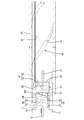
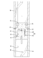
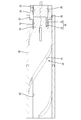
- FIG. 1 is a cross-sectional view showing a state in which the first housing and the second housing have started to be fitted in the connector of the first embodiment.
- FIG. 2 is a cross-sectional view showing a state in which the first housing and the second housing are being fitted.
- FIG. 3 is a cross-sectional view showing a state in which the first housing and the second housing have been fitted.
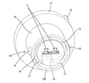
- FIG. 4 is a perspective view of the first housing as viewed obliquely from the rear.
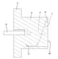
- FIG. 5 is a cross-sectional view of the first housing.
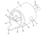
- FIG. 6 is a perspective view of the second housing as viewed diagonally from the front.
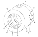
- FIG. 7 is a perspective view of the rotating member as viewed diagonally from the front.
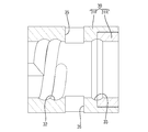
- FIG. 8 is a cross-sectional view of the rotating member.
- FIG. 9 is a perspective view of the operating member viewed diagonally from the front.
- the connectors of the present disclosure are (1) A guide function unit that enables the first housing, the second housing that can be fitted to the first housing, and the first housing and the second housing to approach and separate from each other in a state in which they cannot rotate relative to each other.
- a rotating member that surrounds the first housing and the second housing and is rotatable about an axis parallel to the fitting direction of the first housing and the second housing, and the rotating member is the first housing. It also includes a cam functioning unit that brings the first housing closer to the second housing as it rotates relative to the second housing.
- the connector of the present disclosure can realize space saving.
- the guide function portion is configured by fitting the first guide portion formed in the first housing and the second guide portion formed in the second housing. According to this configuration, the number of parts can be reduced as compared with the case where the guide function unit is a separate part from the first housing and the second housing.
- one of the first guide portion and the second guide portion is a protruding guide portion, and the protruding guide portion of the first housing and the second housing is A spiral guide portion is formed in the housing on the non-formed side, and the first guide portion and the second guide portion are brought into contact with each other by sliding the protruding guide portion on the guide portion. It is preferable that the relative rotation is performed so as to have a positional relationship of fitting. According to this configuration, even if the first guide portion and the second guide portion are displaced in the circumferential direction in the process of bringing the first housing and the second housing close to each other, the spiral guide portion causes the first guide portion and the second guide portion to be displaced from each other.
- the second guide portion can be fitted.
- the cam functional unit has a spiral cam groove formed on one of the inner peripheral surface of the rotating member and the outer peripheral surface of the first housing. It is preferable to have a cam follower formed on the inner peripheral surface of the rotating member and the other peripheral surface of the outer peripheral surface of the first housing and sliding along the cam groove. According to this configuration, since the cam function portion is formed by the rotating member and the first housing, the number of parts is increased as compared with the case where the cam function portion is a separate part from the rotating member and the first housing. Can be reduced.
- the rotating member and the second housing are formed with a holding portion that holds the second housing in a state in which the second housing is not displaced relative to the rotating member in a direction away from the first housing. Is preferable. According to this configuration, when the rotating member is displaced relative to the axial direction while rotating relative to the first housing, the second housing is integrally displaced with the rotating member and is displaced in the axial direction. As a result, the second housing fits with the first housing.
- the rotating member is formed with an opening penetrating from the outer peripheral surface to the inner peripheral surface of the rotating member. According to this configuration, the fitted state of the first housing and the second housing can be visually confirmed from the outside of the rotating member.
- a cylindrical operating member that cannot rotate relative to the first housing and the second housing and has a spiral drive groove formed on the inner peripheral surface is provided. It is preferable that a driven projection that slides on the drive groove is formed on the outer peripheral surface of the rotating member. According to this configuration, when the operating member is displaced relative to the rotating member in the axial direction, the rotating member is rotationally driven, and the first housing and the second housing are fitted or separated from each other. Since the moving direction of the operating member is the axial direction, no space is required for operating the operating member on the outer peripheral side of the first housing and the second housing.
- Example 1 embodying the connector of the present disclosure will be described with reference to FIGS. 1 to 9. It should be noted that the present invention is not limited to these examples, and is indicated by the scope of claims, and is intended to include all modifications within the meaning and scope equivalent to the scope of claims.
- the left side in FIGS. 1 to 3, 5, 6, 8 and 9 is defined as the front.
- the connector of this embodiment includes a first housing 10, a second housing 20, a rotating member 30, and an operating member 40.
- the first housing 10 and the second housing 20 are fitted by approaching each other in the axial direction with the first fitting surface 10F of the first housing 10 and the second fitting surface 20F of the second housing 20 facing each other. Will be done.
- the "fitting direction" of the first housing 10 and the second housing 20 and the "axis direction" of the first housing 10, the second housing 20, the rotating member 30, and the operating member 40 are used interchangeably.
- the first housing 10 is made of synthetic resin and has a cylindrical shape with the axis directed in the front-rear direction as a whole. Inside the first housing 10, a female first terminal fitting 11 connected to the first electric wire 12 is housed. The first electric wire 12 is led out from the front end surface of the first housing 10 to the outside of the first housing 10. The rear end surface of the first housing 10 is a first fitting surface 10F facing the second housing 20.
- a pair of guide portions 13 and one first guide portion 15 are integrally formed in the first housing 10.
- the pair of guide portions 13 have a line-symmetrical shape when the first housing 10 is viewed from the rear.
- Each guide portion 13 has a shape in which a region on the outer peripheral side of the first terminal fitting 11 is recessed in a semicircular groove shape concentric with the first housing 10.
- the inner surfaces of the pair of guide portions 13 function as spiral guide surfaces 14 inclined with respect to the axis of the first housing 10.
- the pair of guide surfaces 14 have spiral directions opposite to each other.
- the first guide portion 15 has a form in which the pair of guide surfaces 14 are recessed from the innermost end to the back (front) in parallel with the axis.
- the first guide unit 15 cooperates with the second guide unit 25 of the second housing 20, which will be described later, to form the guide function unit 45.
- a pair of protruding cam followers 16 separated at a pitch of 180 ° in the circumferential direction are formed on the outer peripheral surface of the first housing 10.
- the cam follower 16 cooperates with the cam groove 32 of the rotating member 30, which will be described later, to form the cam function portion 46.
- a flange portion 17 having a circularly enlarged diameter concentric with the first housing 10 is formed on the outer periphery of the front end portion of the first housing 10.
- a detent projection 18 is formed on the outer periphery of the flange portion 17.
- the second housing 20 is made of synthetic resin and has a cylindrical shape with the axis directed in the front-rear direction as a whole.
- a male second terminal fitting 21 connected to the second electric wire 22 is attached to the inside of the second housing 20.
- the tab 21T at the front end of the second terminal fitting 21 projects forward from the front end surface of the second housing 20.
- the second electric wire 22 is led out from the rear end surface of the second housing 20 to the outside of the second housing 20.
- the front end surface of the second housing 20 is a second fitting surface 20F facing the first housing 10.
- a pair of protruding wall portions 23 and one second guide portion 25 are integrally formed.
- the pair of protruding wall portions 23 have a line-symmetrical shape when the second housing 20 is viewed from the front.
- Each protruding wall portion 23 has a form in which a region on the outer peripheral side of the second terminal fitting 21 is projected in a semicircular shape concentric with the second housing 20.
- the protruding end faces 24 of the pair of protruding wall portions 23 form a spiral shape that is inclined with respect to the axis of the second housing 20.
- the pair of protruding end faces 24 have spiral directions opposite to each other.
- the spiral pitch of the pair of protruding end faces 24 is the same as the spiral pitch of the pair of guiding surfaces 14.
- the second guide portion 25 is in a form of protruding further forward in parallel with the axis from the foremost end portion of the pair of protruding end faces 24.
- the second guide portion 25 is a protruding guide portion.
- a pair of holding protrusions 26 separated at a pitch of 180 ° in the circumferential direction are formed on the outer peripheral surface of the second housing 20.
- the holding protrusion 26 cooperates with the holding groove 33 of the rotating member 30, which will be described later, to form the holding portion 47.
- the rotating member 30 is made of synthetic resin and has a cylindrical shape with the axis directed in the front-rear direction as a whole. As shown in FIGS. 7 and 8, the rotating member 30 is formed by combining a cylindrical front side component 31F and a cylindrical rear side component 31R coaxially and back and forth. A spiral cam groove 32 is formed on the inner peripheral surface of the front component 31F. The formation range of the cam groove 32 in the axial direction is a region extending from the front end of the rotating member 30 (front component 31F) to a position in front of the rear end of the rotating member 30 (front component 31F).
- the front end of the cam groove 32 is opened on the front end surface of the rotating member 30 as an inlet for allowing the cam follower 16 of the first housing 10 to enter the cam groove 32.
- the spiral pitch of the cam groove 32 is set to a dimension smaller than the spiral pitch of the drive groove 41 of the operating member 40, which will be described later. As shown in FIG. 1, the cam groove 32 cooperates with the cam follower 16 of the first housing 10 described above to form the cam function unit 46.
- a holding groove 33 is formed in a region of the inner peripheral surface of the rotating member 30 behind the cam groove 32.
- the holding groove 33 is not spiral, but forms a perfect circle on a virtual plane orthogonal to the axis.
- the holding groove 33 is composed of a notch having a quarter arc cross section formed on the inner circumference of the rear end portion of the front component 31F and a notch having a quarter arc cross section formed on the inner circumference of the front end portion of the rear component 31R. There is.
- the holding groove 33 cooperates with the holding protrusion 26 of the second housing 20 to form the holding portion 47.
- a pair of driven protrusions 34 separated at a pitch of 180 ° in the circumferential direction are formed on the outer peripheral surface of the rotating member 30.
- the driven protrusion 34 cooperates with the drive groove 41 of the operating member 40 described later to form the rotational force transmission unit 48.
- a pair of openings 35 are formed in the rotating member 30.
- the opening 35 has a form of penetrating from the outer peripheral surface to the inner peripheral surface of the rotating member 30. In the axial direction, the opening 35 is arranged between the cam groove 32 and the holding groove 33.
- the first fitting surface 10F of the first housing 10 and the second fitting surface 20F of the second housing 20 abut between the cam groove 32 and the holding groove 33.
- the operating member 40 has a cylindrical shape with its axis oriented in the front-rear direction as a whole.
- a spiral drive groove 41 is formed on the inner peripheral surface of the operating member 40.
- the spiral pitch of the drive groove 41 is set to a dimension larger than the spiral pitch of the cam groove 32 of the rotating member 30.
- the front end of the drive groove 41 is open to the front end surface of the operating member 40.
- One detent groove 42 is formed on the inner peripheral surface of the operating member 40.
- the front end of the detent groove 42 is open to the front end surface of the operating member 40.
- the detent groove 42 extends in a straight line parallel to the axis.
- the second housing 20 and the rotating member 30 are assembled.
- the front part 31F and the rear part 31R are separated, the front part 31F is fitted from the front to the outer circumference of the first housing 10, and the rear part 31R is rearward to the outer circumference of the first housing 10. Fit out from.
- the holding groove 33 is formed, and at the same time, the holding projection 26 is fitted into the holding groove 33.
- the holding projection 26 is caught in the holding groove 33, so that the relative displacement of the second housing 20 and the rotating member 30 in the axial direction (both front and rear directions) is impossible. become.
- the holding projection 26 and the holding groove 33 are in sliding contact with each other so that the second housing 20 and the rotating member 30 can rotate relatively.
- the first housing 10 and the rotating member 30 are assembled.
- the rear end portion of the first housing 10 is inserted into the rotating member 30 from the front of the rotating member 30.
- the cam follower 16 of the second housing 20 is made to enter the front end portion of the cam groove 32.
- the first housing 10 and the second housing 20 are not fitted, and the first guide portion 15 and the second guide portion 25 are also not fitted.
- the first housing 10, the second housing 20, and the rotating member 30 are assembled.
- the front end portion of the operating member 40 is fitted onto the rear end portion of the rotating member 30, and the driven protrusion 34 enters the front end portion of the drive groove 41. Let me. Next, the detent projection 18 of the first housing 10 is fitted to the front end of the detent groove 42. In this state, the relative rotation of the first housing 10 and the second housing 20 with respect to the operating member 40 becomes impossible, but the operating member 40 is relatively displaced forward in the axial direction with respect to the first housing 10 and the second housing 20. Can be done.
- the first housing 10 and the operating member 40 are brought closer to each other in the axial direction without relative rotation.
- the drive groove 41 of the operating member 40 and the driven projection 34 of the rotating member 30 slide, so that the rotating member 30 rotates relative to the first housing 10 and the second housing 20 due to the inclination of the drive groove 41.
- frictional resistance is generated due to the sliding between the cam groove 32 and the cam follower 16, but since the spiral pitch of the drive groove 41 is larger than the spiral pitch of the cam groove 32, it is applied to the operating member 40 in the axial direction. Even if the operating force is small, the rotating member 30 can be reliably rotated.
- the connector of the first embodiment includes a first housing 10, a second housing 20 that can be fitted with the first housing 10, a guide function portion 45, a rotating member 30, and a cam function portion 46.
- the guide function portion 45 is a functional portion that enables the first housing 10 and the second housing 20 to approach and separate from each other in a state in which they cannot rotate relative to each other.
- the rotating member 30 surrounds the first housing 10 and the second housing 20. The rotating member 30 can rotate about an axis parallel to the fitting direction of the first housing 10 and the second housing 20. In short, the rotating member 30 is rotatable about an axis.
- the cam function unit 46 brings the first housing 10 and the second housing 20 closer to each other as the rotating member 30 rotates relative to the first housing 10 and the second housing 20.
- the connector of the present disclosure can realize space saving.
- the guide function portion 45 is configured by fitting the first guide portion 15 formed in the first housing 10 and the second guide portion 25 formed in the second housing 20.
- the first guide portion 15 constituting the guide function portion 45 is integrally formed with the first housing 10
- the second guide portion 25 constituting the guide function portion 45 is integrally formed with the second housing 20. Therefore, as compared with the case where the guide function unit 45 is a separate component from the first housing 10 and the second housing 20, the connector of this embodiment can reduce the number of components.
- the second guide portion 25 is a protruding guide portion.
- a spiral guide portion 13 is formed in the second housing 20 on the side of the first housing 10 and the second housing 20 on which the protruding guide portion (second guide portion 25) is not formed.
- the first guide portion 15 and the second guide portion 25 are brought into sliding contact with the guide portion 13 in a protruding guide portion (second guide portion 25) so as to rotate relative to each other so as to be in a positional relationship of fitting with each other. It has become.
- the front end of the second guide portion 25 is in sliding contact with the spiral guide portion 13. Since the second guide portion 25 is guided to approach the first guide portion 15 by this sliding contact, the first guide portion 15 and the second guide portion 25 can be securely fitted.
- the cam function unit 46 includes a spiral cam groove 32 formed on the inner peripheral surface of the rotating member 30, and a cam follower 16 formed on the outer peripheral surface of the first housing 10.
- the cam follower 16 slides along the cam groove 32 as the rotating member 30 and the first housing 10 rotate relative to each other.
- the cam groove 32 constituting the cam function portion 46 is integrally formed with the rotating member 30, and the cam follower 16 constituting the cam function portion 46 is integrally formed with the first housing 10. Therefore, the number of parts of the connector of this embodiment can be reduced as compared with the case where the cam function portion 46 is a separate component from the rotating member 30 and the first housing 10.
- the rotating member 30 is integrally formed with a holding groove 33 constituting the holding portion 47.
- a holding protrusion 26 forming a holding portion 47 is integrally formed in the second housing 20.
- the holding groove 33 and the holding protrusion 26 hold the second housing 20 in a state in which the second housing 20 is not displaced relative to the rotating member 30 in the direction away from the first housing 10. According to this configuration, when the rotating member 30 is relatively displaced forward in the axial direction while rotating relative to the first housing 10, the second housing 20 is integrally displaced forward in the axial direction together with the rotating member 30. .. As a result, the second housing 20 fits into the first housing 10.
- the rotating member 30 is formed with an opening 35 penetrating from the outer peripheral surface to the inner peripheral surface of the rotating member 30. According to this configuration, the fitted state of the first housing 10 and the second housing 20 can be visually confirmed from the outside of the rotating member 30.
- the connector of this embodiment is non-rotatable relative to the first housing 10 and the second housing 20, and includes a cylindrical operating member 40 having a spiral drive groove 41 formed on the inner peripheral surface.
- a driven projection 34 that slides on the drive groove 41 is formed on the outer peripheral surface of the rotating member 30.
- the present invention is not limited to the examples described in the above description and drawings, but is shown by the scope of claims.
- the present invention includes the meaning equivalent to the scope of claims and all modifications within the scope of claims, and is intended to include the following embodiments.
- the first guide portion has a concave shape and the second guide portion has a protruding shape, but the first guide portion may have a protruding shape and the second guide portion may have a concave shape.
- the guide function unit is formed in the first housing and the second housing, but the guide function unit may be a separate component from the first housing and the second housing.
- the spiral guide portion is formed in the first housing and the second housing, but the form may not have the spiral guide portion.
- the cam function portion is formed of the rotating member and the first housing, but the cam function portion may be a separate component from the rotating member and the first housing.
- the cam groove is formed on the inner peripheral surface of the rotating member and the cam follower is formed on the outer peripheral surface of the first housing.
- the cam groove is formed on the outer peripheral surface of the first housing and the cam follower is formed on the inner peripheral surface of the rotating member. It may be formed on the peripheral surface.
- the holding portion is composed of a holding groove formed on the inner peripheral surface of the rotating member and a holding protrusion formed on the outer peripheral surface of the second housing.
- the holding portion is formed on the outer peripheral surface of the second housing.
- the rotating member may be composed of a holding groove formed on the surface and a holding protrusion formed on the inner peripheral surface of the rotating member.
- the rotating member has an opening, but the rotating member may have no opening.
- the rotating member is rotated by using the operating member, but the rotating member may be directly rotated without using the operating member.
- the operating member and the first housing are fitted as a means for making the operating member relatively non-rotatable with respect to the first housing and the second housing, but the operating member and the second housing are fitted. You may let me.
- the first housing has a female terminal fitting and the second housing has a male terminal fitting, but the first housing has a male terminal fitting and the second housing has a female terminal fitting. May be good.
Landscapes
- Details Of Connecting Devices For Male And Female Coupling (AREA)
Abstract
コネクタは、第1ハウジング(10)と、第1ハウジング(10)と嵌合可能な第2ハウジング(20)と、第1ハウジング(10)と第2ハウジング(20)が相対回転不能な状態で接近・離隔することを可能にするガイド機能部(45)と、第1ハウジング(10)と第2ハウジング(20)を包囲し、第1ハウジング(10)と第2ハウジング(20)の嵌合方向と平行な軸線を中心として回転可能な回転部材(30)と、回転部材(30)が、第1ハウジング(10)及び第2ハウジング(20)に対して相対回転するのに伴い、第1ハウジング(10)と第2ハウジング(20)を接近させるカム機能部(46)と、を備えている。
Description
本開示は、コネクタに関するものである。
特許文献1には、嵌合時に必要な操作力を低減したコネクタが開示されている。このコネクタは、ハウジングにレバーを回動可能に取り付けて構成されている。コネクタを相手側コネクタと嵌合する際には、レバーのカム溝と相手側コネクタのカムフォロアとを係合させた状態で、レバーの操作部に回転力を付与する。すると、テコの原理による倍力作用によって、レバーに付与すべき操作力が低減される。
レバーは、コネクタと相手側コネクタの嵌合方向と直交する軸線を中心として回動するので、コネクタの周囲には、レバーの操作部を回動させるための円弧状のスペースが必要である。円弧状のスペースは、コネクタの外周側へ膨らむように確保しなければならないため、狭い空間内では嵌合作業を行うことが困難である。
本開示のコネクタは、上記のような事情に基づいて完成されたものであって、省スペース化を実現することを目的とする。
本開示は、
第1ハウジングと、
前記第1ハウジングと嵌合可能な第2ハウジングと、
前記第1ハウジングと前記第2ハウジングが相対回転不能な状態で接近・離隔することを可能にするガイド機能部と、
前記第1ハウジングと前記第2ハウジングを包囲し、前記第1ハウジングと前記第2ハウジングの嵌合方向と平行な軸線を中心として回転可能な回転部材と、
前記回転部材が前記第1ハウジング及び前記第2ハウジングに対して相対回転するのに伴い、前記第1ハウジングと前記第2ハウジングを接近させるカム機能部とを備えている。
第1ハウジングと、
前記第1ハウジングと嵌合可能な第2ハウジングと、
前記第1ハウジングと前記第2ハウジングが相対回転不能な状態で接近・離隔することを可能にするガイド機能部と、
前記第1ハウジングと前記第2ハウジングを包囲し、前記第1ハウジングと前記第2ハウジングの嵌合方向と平行な軸線を中心として回転可能な回転部材と、
前記回転部材が前記第1ハウジング及び前記第2ハウジングに対して相対回転するのに伴い、前記第1ハウジングと前記第2ハウジングを接近させるカム機能部とを備えている。
本開示によれば、省スペース化を実現することができる。
[本開示の実施形態の説明]
最初に本開示の実施形態を列記して説明する。
本開示のコネクタは、
(1)第1ハウジングと、前記第1ハウジングと嵌合可能な第2ハウジングと、前記第1ハウジングと前記第2ハウジングが相対回転不能な状態で接近・離隔することを可能にするガイド機能部と、前記第1ハウジングと前記第2ハウジングを包囲し、前記第1ハウジングと前記第2ハウジングの嵌合方向と平行な軸線を中心として回転可能な回転部材と、前記回転部材が前記第1ハウジング及び前記第2ハウジングに対して相対回転するのに伴い、前記第1ハウジングと前記第2ハウジングを接近させるカム機能部とを備えている。本開示の構成によれば、回転部材を回転させると、カム機能部によって第1ハウジングと第2ハウジングが接近して嵌合する。回転部材は、第1ハウジングと第2ハウジングの嵌合方向と平行な軸線を中心として回転するので、両ハウジングの外周側には、円弧状に膨らむ操作スペースを確保する必要がない。したがって、本開示のコネクタは、省スペース化を実現することができる。
最初に本開示の実施形態を列記して説明する。
本開示のコネクタは、
(1)第1ハウジングと、前記第1ハウジングと嵌合可能な第2ハウジングと、前記第1ハウジングと前記第2ハウジングが相対回転不能な状態で接近・離隔することを可能にするガイド機能部と、前記第1ハウジングと前記第2ハウジングを包囲し、前記第1ハウジングと前記第2ハウジングの嵌合方向と平行な軸線を中心として回転可能な回転部材と、前記回転部材が前記第1ハウジング及び前記第2ハウジングに対して相対回転するのに伴い、前記第1ハウジングと前記第2ハウジングを接近させるカム機能部とを備えている。本開示の構成によれば、回転部材を回転させると、カム機能部によって第1ハウジングと第2ハウジングが接近して嵌合する。回転部材は、第1ハウジングと第2ハウジングの嵌合方向と平行な軸線を中心として回転するので、両ハウジングの外周側には、円弧状に膨らむ操作スペースを確保する必要がない。したがって、本開示のコネクタは、省スペース化を実現することができる。
(2)前記ガイド機能部が、前記第1ハウジングに形成された第1ガイド部と、前記第2ハウジングに形成された第2ガイド部とを嵌合して構成されていることが好ましい。この構成によれば、ガイド機能部が第1ハウジング及び第2ハウジングとは別体の部品である場合に比べると、部品点数を削減することができる。
(3)(2)において、前記第1ガイド部と前記第2ガイド部のうち一方は、突起状のガイド部であり、前記第1ハウジングと前記第2ハウジングのうち前記突起状のガイド部が形成されていない側のハウジングには、螺旋状の誘導部が形成され、前記第1ガイド部と前記第2ガイド部は、前記誘導部に前記突起状のガイド部を摺接させることによって、互いに嵌合する位置関係となるように相対回転するようになっていることが好ましい。この構成によれば、第1ハウジングと第2ハウジングを接近させる過程で、第1ガイド部と第2ガイド部が周方向に位置ずれしていても、螺旋状の誘導部によって第1ガイド部と第2ガイド部を嵌合させることができる。
(4)(1)~(3)において、前記カム機能部が、前記回転部材の内周面と前記第1ハウジングの外周面のうち一方の周面に形成された螺旋状のカム溝と、前記回転部材の内周面と前記第1ハウジングの外周面のうち他方の周面に形成され、前記カム溝に沿って摺動するカムフォロアとを備えていることが好ましい。この構成によれば、カム機能部が回転部材と第1ハウジングとに形成されているので、カム機能部が回転部材及び第1ハウジングとは別体の部品である場合に比べると、部品点数を削減することができる。
(5)(4)において、前記回転部材と前記第2ハウジングには、前記第2ハウジングを前記回転部材に対し前記第1ハウジングから離隔する方向へ相対変位しない状態に保持する保持部が形成されていることが好ましい。この構成によれば、回転部材を、第1ハウジングに対して相対回転させながら軸線方向へ相対変位させると、第2ハウジングが回転部材と一体となって軸線方向へ変位する。これにより、第2ハウジングが第1ハウジングと嵌合する。
(6)(1)から(5)において、前記回転部材には、前記回転部材の外周面から内周面に貫通する開口部が形成されていることが好ましい。この構成よれば、第1ハウジングと第2ハウジングの嵌合状態を、回転部材の外部から目視で確認することができる。
(7)(1)から(6)において、前記第1ハウジング及び前記第2ハウジングに対して相対回転不能であり、内周面に螺旋状の駆動溝が形成された筒状の操作部材を備え、前記回転部材の外周面には、前記駆動溝と摺動する従動突起が形成されていることが好ましい。この構成によれば、操作部材を回転部材に対して軸線方向に相対変位させると、回転部材が回転駆動され、第1ハウジングと第2ハウジングが嵌合又は離隔する。操作部材の移動方向は軸線方向なので、第1ハウジング及び第2ハウジングの外周側には、操作部材を操作するためのスペースが不要である。
[本開示の実施形態の詳細]
[実施例1]
本開示のコネクタを具体化した実施例1を、図1~図9を参照して説明する。なお、本発明はこれらの例示に限定されるものではなく、特許請求の範囲によって示され、特許請求の範囲と均等の意味および範囲内でのすべての変更が含まれることが意図される。本実施例1において、前後の方向については、図1~3,5,6,8,9における左方を前方と定義する。
[実施例1]
本開示のコネクタを具体化した実施例1を、図1~図9を参照して説明する。なお、本発明はこれらの例示に限定されるものではなく、特許請求の範囲によって示され、特許請求の範囲と均等の意味および範囲内でのすべての変更が含まれることが意図される。本実施例1において、前後の方向については、図1~3,5,6,8,9における左方を前方と定義する。
図1~3に示すように、本実施例のコネクタは、第1ハウジング10と、第2ハウジング20と、回転部材30と、操作部材40とを備えている。第1ハウジング10と第2ハウジング20は、第1ハウジング10の第1嵌合面10Fと第2ハウジング20の第2嵌合面20Fとを対向させた状態で軸線方向に接近することによって嵌合される。以下、第1ハウジング10と第2ハウジング20の「嵌合方向」と、第1ハウジング10、第2ハウジング20、回転部材30及び操作部材40の「軸線方向」は同義で用いる。
第1ハウジング10は、合成樹脂製であり、全体として軸線を前後方向に向けた円柱形をなす。第1ハウジング10の内部には、第1電線12に接続された雌形の第1端子金具11が収容されている。第1電線12は、第1ハウジング10の前端面から第1ハウジング10の外部へ導出されている。第1ハウジング10の後端面は、第2ハウジング20と対向する第1嵌合面10Fとなっている。
図4,5に示すように、第1ハウジング10には、一対の誘導部13と、1つの第1ガイド部15が一体に形成されている。一対の誘導部13は、第1ハウジング10を後方から見た背面視において、線対称の形状である。各誘導部13は、第1端子金具11よりも外周側の領域を第1ハウジング10と同心の半円形の溝状に凹ませた形態である。一対の誘導部13の奥面は、第1ハウジング10の軸線に対して傾斜した螺旋状の誘導面14として機能する。一対の誘導面14は、螺旋の向きが互いに逆向きである。
第1ガイド部15は、一対の誘導面14における最も奥側の端部から、さらに奥方(前方)へ軸線と平行に凹ませた形態である。第1ガイド部15は、後述する第2ハウジング20の第2ガイド部25と協動して、ガイド機能部45を構成する。
図4に示すように、第1ハウジング10の外周面には、周方向において180°ピッチで離隔した一対の突起状のカムフォロア16が形成されている。カムフォロア16は、後述する回転部材30のカム溝32と協動してカム機能部46を構成する。第1ハウジング10の前端部外周には、第1ハウジング10と同心の円形状に拡径した形態のフランジ部17が形成されている。フランジ部17の外周には、回り止め突起18が形成されている。
第2ハウジング20は、合成樹脂製であり、全体として軸線を前後方向に向けた円柱形をなす。図1に示すように、第2ハウジング20の内部には、第2電線22に接続された雄形の第2端子金具21が取り付けられている。図6に示すように、第2端子金具21の前端のタブ21Tは、第2ハウジング20の前端面から前方へ突出している。第2電線22は、第2ハウジング20の後端面から第2ハウジング20の外部へ導出されている。第2ハウジング20の前端面は、第1ハウジング10と対向する第2嵌合面20Fとなっている。
第2ハウジング20には、一対の突壁部23と、1つの第2ガイド部25が一体に形成されている。一対の突壁部23は、第2ハウジング20を前方から見た正面視において、線対称の形状である。各突壁部23は、第2端子金具21よりも外周側の領域を第2ハウジング20と同心の半円形に突出させた形態である。一対の突壁部23の突出端面24は、第2ハウジング20の軸線に対して傾斜した螺旋状をなしている。一対の突出端面24は、螺旋の向きが互いに逆向きである。一対の突出端面24の螺旋ピッチは、一対の誘導面14の螺旋ピッチと同じである。
第2ガイド部25は、一対の突出端面24における最前端部から、さらに前方へ軸線と平行に突出した形態である。第2ガイド部25は突起状のガイド部である。第2ハウジング20の外周面には、周方向において180°ピッチで離隔した一対の保持突起26が形成されている。保持突起26は、後述する回転部材30の保持溝33と協動して保持部47を構成する。
回転部材30は、合成樹脂製であり、全体として軸線を前後方向に向けた円柱形をなす。図7,8に示すように、回転部材30は、円筒形の前側部品31Fと円筒形の後側部品31Rとを、同軸状にかつ前後に合体して構成されている。前側部品31Fの内周面には、螺旋状のカム溝32が形成されている。軸線方向におけるカム溝32の形成範囲は、回転部材30(前側部品31F)の前端から、回転部材30(前側部品31F)の後端よりも前方の位置に至る領域である。カム溝32の前端は、回転部材30の前端面において、第1ハウジング10のカムフォロア16をカム溝32に進入させるための入口として開口している。カム溝32の螺旋ピッチは、後述する操作部材40の駆動溝41の螺旋ピッチより小さい寸法に設定されている。図1に示すように、カム溝32は、前述の第1ハウジング10のカムフォロア16と協動してカム機能部46を構成する。
回転部材30の内周面のうちカム溝32よりも後方の領域には、保持溝33が形成されている。保持溝33は、螺旋状ではなく、軸線と直交する仮想平面上で真円をなす。保持溝33は、前側部品31Fの後端部内周に形成した四半円弧形断面の切欠部と、後側部品31Rの前端部内周に形成した四半円弧形断面の切欠部とによって構成されている。保持溝33は、前述の第2ハウジング20の保持突起26と協動して保持部47を構成する。
回転部材30の外周面には、周方向において180°ピッチで離隔した一対の従動突起34が形成されている。従動突起34は、後述する操作部材40の駆動溝41と協動して回転力伝達部48を構成する。回転部材30には、一対の開口部35が形成されている。開口部35は、回転部材30の外周面から内周面まで貫通した形態である。軸線方向において、開口部35は、カム溝32と保持溝33との間に配されている。カム溝32と保持溝33との間では、第1ハウジング10の第1嵌合面10Fと第2ハウジング20の第2嵌合面20Fとが突き当たるようになっている。
操作部材40は、全体として軸線を前後方向に向けた円柱形をなす。操作部材40の内周面には、螺旋状の駆動溝41が形成されている。駆動溝41の螺旋ピッチは、回転部材30のカム溝32の螺旋ピッチよりも大きい寸法に設定されている。駆動溝41の前端は、操作部材40の前端面に開口している。操作部材40の内周面には、1本の回り止め溝42が形成されている。回り止め溝42の前端は、操作部材40の前端面に開口している。回り止め溝42は、軸線と平行に一直線状に延びている。
次に、本実施例のコネクタにおいて第1ハウジング10と第2ハウジング20を嵌合するための作業手順を説明する。まず、第2ハウジング20と回転部材30とを組み付ける。組付けに際しては、前側部品31Fと後側部品31Rを分離し、前側部品31Fを第1ハウジング10の外周に対し前方から外嵌するとともに、後側部品31Rを第1ハウジング10の外周に対し後方から外嵌する。前側部品31Fと後側部品31Rを合体させると、保持溝33が構成されると同時に、保持溝33に保持突起26が嵌合される。以上によって、回転部材30と第2ハウジング20との組付けが完了する。
回転部材30と第2ハウジング20とが組み付けられた状態では、保持突起26が保持溝33に引っ掛かることによって、第2ハウジング20と回転部材30との軸線方向(前後両方向)への相対変位が不能になる。保持突起26と保持溝33とが摺接することによって、第2ハウジング20と回転部材30とが相対的に回転し得るようになっている。
次に、第1ハウジング10と回転部材30とを組み付ける。組付けに際しては、回転部材30に対し、回転部材30の前方から第1ハウジング10の後端部を挿入する。このとき、第2ハウジング20のカムフォロア16をカム溝32の前端部に進入させる。この時点では、第1ハウジング10と第2ハウジング20は未嵌合であり、第1ガイド部15と第2ガイド部25も未嵌合である。以上により、第1ハウジング10と第2ハウジング20と回転部材30とが組み付けられる。
第1ハウジング10と第2ハウジング20と回転部材30を組み付けた後は、操作部材40の前端部を回転部材30の後端部に外嵌し、従動突起34を駆動溝41の前端部に進入させる。次に、第1ハウジング10の回り止め突起18を回り止め溝42の前端部に嵌合する。この状態では、操作部材40に対する第1ハウジング10及び第2ハウジング20の相対回転が不能になるが、第1ハウジング10及び第2ハウジング20に対して操作部材40を軸線方向前方へ相対変位させることができる。
この後、第1ハウジング10と操作部材40を、相対回転させずに軸線方向に接近させる。すると、操作部材40の駆動溝41と回転部材30の従動突起34が摺動するので、駆動溝41の傾斜によって、回転部材30が第1ハウジング10及び第2ハウジング20に対して相対的に回転駆動される。このとき、カム溝32とカムフォロア16との摺動に起因する摩擦抵抗が生じるが、駆動溝41の螺旋ピッチは、カム溝32の螺旋ピッチよりも大きいので、操作部材40に付与する軸線方向の操作力が小さくても、確実に回転部材30を回転させることができる。
回転部材30が相対回転すると、カム溝32とカムフォロア16が摺動し、カム溝32の傾斜によって、回転部材30と第1ハウジング10とが軸線方向に相対変位する。このとき、第1ハウジング10に対する回転部材30の相対変位方向は、前方である。回転部材30と第2ハウジング20は、保持溝33と保持突起26との嵌合によって一体的に移動する。したがって、操作部材40と第1ハウジング10を接近させると、第1ハウジング10と第2ハウジング20が接近して嵌合される。
本実施例1のコネクタは、第1ハウジング10と、第1ハウジング10と嵌合可能な第2ハウジング20と、ガイド機能部45と、回転部材30と、カム機能部46とを備えている。ガイド機能部45は、第1ハウジング10と第2ハウジング20が相対回転不能な状態で接近・離隔することを可能にする機能部位である。回転部材30は、第1ハウジング10と第2ハウジング20を包囲する。回転部材30は、第1ハウジング10と第2ハウジング20の嵌合方向と平行な軸線を中心として回転可能である。端的には、回転部材30は軸線周りに回転可能である。カム機能部46は、回転部材30が、第1ハウジング10及び第2ハウジング20に対して相対回転するのに伴い、第1ハウジング10と第2ハウジング20を接近させる。
この構成によれば、回転部材30を回転させると、カム機能部46によって第1ハウジング10と第2ハウジング20が接近して嵌合する。回転部材30は、第1ハウジング10と第2ハウジング20の嵌合方向と平行な軸線を中心として回転するので、両ハウジングの外周側には、円弧状に膨らむ操作スペースを確保する必要がない。したがって、本開示のコネクタは、省スペース化を実現することができる。
ガイド機能部45は、第1ハウジング10に形成された第1ガイド部15と、第2ハウジング20に形成された第2ガイド部25とを嵌合して構成されている。ガイド機能部45を構成する第1ガイド部15は第1ハウジング10に一体に形成され、ガイド機能部45を構成する第2ガイド部25は第2ハウジング20に一体に形成されている。したがって、ガイド機能部45が第1ハウジング10及び第2ハウジング20とは別体の部品である場合に比べると、本実施例のコネクタは、部品点数を削減することができる。
第1ガイド部15と第2ガイド部25のうち第2ガイド部25は、突起状のガイド部である。第1ハウジング10と第2ハウジング20のうち突起状のガイド部(第2ガイド部25)が形成されていない側の第2ハウジング20には、螺旋状の誘導部13が形成されている。第1ガイド部15と第2ガイド部25は、誘導部13に突起状のガイド部(第2ガイド部25)を摺接させることによって、互いに嵌合する位置関係となるように相対回転するようになっている。
この構成によれば、第1ハウジング10と第2ハウジング20を接近させる過程で、第1ガイド部15と第2ガイド部25が周方向に位置ずれしていても、第2ガイド部25の前端部が螺旋状の誘導部13に摺接する。この摺接によって、第2ガイド部25が第1ガイド部15に接近するように誘導されるので、第1ガイド部15と第2ガイド部25を確実に嵌合させることができる。
カム機能部46は、回転部材30の内周面に形成された螺旋状のカム溝32と、第1ハウジング10の外周面に形成されたカムフォロア16とを備えて構成されている。カムフォロア16は、回転部材30と第1ハウジング10が相対回転するのに伴い、カム溝32に沿って摺動する。カム機能部46を構成するカム溝32が回転部材30に一体に形成され、カム機能部46を構成するカムフォロア16が第1ハウジング10に一体に形成されている。したがって、カム機能部46が回転部材30及び第1ハウジング10とは別体の部品である場合に比べると、本実施例のコネクタは、部品点数を削減することができる。
回転部材30には、保持部47を構成する保持溝33が一体に形成されている。第2ハウジング20には、保持部47を構成する保持突起26が一体に形成されている。保持溝33と保持突起26は、第2ハウジング20を回転部材30に対して第1ハウジング10から離隔する方向へ相対変位しない状態に保持する。この構成によれば、回転部材30を、第1ハウジング10に対して相対回転させながら軸線方向前方へ相対変位させると、第2ハウジング20を回転部材30と一体となって軸線方向前方へ変位する。これにより、第2ハウジング20が第1ハウジング10と嵌合する。
回転部材30には、回転部材30の外周面から内周面に貫通する開口部35が形成されている。この構成よれば、第1ハウジング10と第2ハウジング20の嵌合状態を、回転部材30の外部から目視で確認することができる。
本実施例のコネクタは、第1ハウジング10及び第2ハウジング20に対して相対回転不能であり、内周面に螺旋状の駆動溝41が形成された筒状の操作部材40を備えている。回転部材30の外周面には、駆動溝41と摺動する従動突起34が形成されている。この構成によれば、操作部材40を回転部材30に対して軸線方向に相対変位させると、回転部材30が回転駆動され、第1ハウジング10と第2ハウジング20が嵌合又は離隔する。操作部材40の移動方向は軸線方向なので、第1ハウジング10及び第2ハウジング20の外周側には、操作部材40を操作するためのスペースが不要である。
[他の実施例]
本発明は、上記記述及び図面によって説明した実施例に限定されるものではなく、特許請求の範囲によって示される。本発明には、特許請求の範囲と均等の意味及び特許請求の範囲内でのすべての変更が含まれ、下記のような実施形態も含まれることが意図される。
上記実施例では、第1ガイド部を凹んだ形状とし、第2ガイド部を突出した形状としたが、第1ガイド部を突出した形状とし、第2ガイド部を凹んだ形状としてもよい。
上記実施例では、ガイド機能部を第1ハウジングと第2ハウジングとに形成したが、ガイド機能部は、第1ハウジング及び第2ハウジングとは別体の部品であってもよい。
上記実施例では、第1ハウジングと第2ハウジングに螺旋状の誘導部を形成したが、螺旋状の誘導部を有しない形態としてもよい。
上記実施例では、カム機能部を回転部材と第1ハウジングとに形成したが、カム機能部が回転部材及び第1ハウジングとは別体の部品であってもよい。
上記実施例では、カム溝を回転部材の内周面に形成し、カムフォロアを第1ハウジングの外周面に形成したが、カム溝を第1ハウジングの外周面に形成し、カムフォロアを回転部材の内周面に形成してもよい。
上記実施例では、保持部が、回転部材の内周面に形成した保持溝と、第2ハウジングの外周面に形成した保持突起とから構成されているが、保持部は、第2ハウジングの外周面に形成した保持溝と、回転部材の内周面に形成した保持突起とによって構成されていてもよい。
上記実施例では、回転部材に開口部を形成したが、回転部材は開口部を有しない形態であってもよい。
上記実施例では、操作部材を用いて回転部材を回転させたが、操作部材を用いずに、回転部材を直接回転させてもよい。
上記実施例では、第1ハウジング及び第2ハウジングに対して操作部材を相対回転不能にする手段として、操作部材と第1ハウジングとを嵌合させたが、操作部材と第2ハウジングとを嵌合させてもよい。
上記実施例では、第1ハウジングが雌端子金具を有し、第2ハウジングが雄端子金具を有するが、第1ハウジングが雄端子金具を有し、第2ハウジングが雌端子金具を有していてもよい。
本発明は、上記記述及び図面によって説明した実施例に限定されるものではなく、特許請求の範囲によって示される。本発明には、特許請求の範囲と均等の意味及び特許請求の範囲内でのすべての変更が含まれ、下記のような実施形態も含まれることが意図される。
上記実施例では、第1ガイド部を凹んだ形状とし、第2ガイド部を突出した形状としたが、第1ガイド部を突出した形状とし、第2ガイド部を凹んだ形状としてもよい。
上記実施例では、ガイド機能部を第1ハウジングと第2ハウジングとに形成したが、ガイド機能部は、第1ハウジング及び第2ハウジングとは別体の部品であってもよい。
上記実施例では、第1ハウジングと第2ハウジングに螺旋状の誘導部を形成したが、螺旋状の誘導部を有しない形態としてもよい。
上記実施例では、カム機能部を回転部材と第1ハウジングとに形成したが、カム機能部が回転部材及び第1ハウジングとは別体の部品であってもよい。
上記実施例では、カム溝を回転部材の内周面に形成し、カムフォロアを第1ハウジングの外周面に形成したが、カム溝を第1ハウジングの外周面に形成し、カムフォロアを回転部材の内周面に形成してもよい。
上記実施例では、保持部が、回転部材の内周面に形成した保持溝と、第2ハウジングの外周面に形成した保持突起とから構成されているが、保持部は、第2ハウジングの外周面に形成した保持溝と、回転部材の内周面に形成した保持突起とによって構成されていてもよい。
上記実施例では、回転部材に開口部を形成したが、回転部材は開口部を有しない形態であってもよい。
上記実施例では、操作部材を用いて回転部材を回転させたが、操作部材を用いずに、回転部材を直接回転させてもよい。
上記実施例では、第1ハウジング及び第2ハウジングに対して操作部材を相対回転不能にする手段として、操作部材と第1ハウジングとを嵌合させたが、操作部材と第2ハウジングとを嵌合させてもよい。
上記実施例では、第1ハウジングが雌端子金具を有し、第2ハウジングが雄端子金具を有するが、第1ハウジングが雄端子金具を有し、第2ハウジングが雌端子金具を有していてもよい。
10…第1ハウジング
10F…第1嵌合面
11…第1端子金具
12…第1電線
13…誘導部
14…誘導面
15…第1ガイド部
16…カムフォロア
17…フランジ部
18…回り止め突起
20…第2ハウジング
20F…第2嵌合面
21…第2端子金具
21T…タブ
22…第2電線
23…突壁部
24…突出端面
25…第2ガイド部
26…保持突起
30…回転部材
31F…前側部品
31R…後側部品
32…カム溝
33…保持溝
34…従動突起
35…開口部
40…操作部材
41…駆動溝
42…回り止め溝
45…ガイド機能部
46…カム機能部
47…保持部
48…回転力伝達部
10F…第1嵌合面
11…第1端子金具
12…第1電線
13…誘導部
14…誘導面
15…第1ガイド部
16…カムフォロア
17…フランジ部
18…回り止め突起
20…第2ハウジング
20F…第2嵌合面
21…第2端子金具
21T…タブ
22…第2電線
23…突壁部
24…突出端面
25…第2ガイド部
26…保持突起
30…回転部材
31F…前側部品
31R…後側部品
32…カム溝
33…保持溝
34…従動突起
35…開口部
40…操作部材
41…駆動溝
42…回り止め溝
45…ガイド機能部
46…カム機能部
47…保持部
48…回転力伝達部
Claims (7)
- 第1ハウジングと、
前記第1ハウジングと嵌合可能な第2ハウジングと、
前記第1ハウジングと前記第2ハウジングが相対回転不能な状態で接近・離隔することを可能にするガイド機能部と、
前記第1ハウジングと前記第2ハウジングを包囲し、前記第1ハウジングと前記第2ハウジングの嵌合方向と平行な軸線を中心として回転可能な回転部材と、
前記回転部材が前記第1ハウジング及び前記第2ハウジングに対して相対回転するのに伴い、前記第1ハウジングと前記第2ハウジングを接近させるカム機能部とを備えているコネクタ。 - 前記ガイド機能部が、
前記第1ハウジングに形成された第1ガイド部と、
前記第2ハウジングに形成された第2ガイド部とを嵌合して構成されている請求項1に記載のコネクタ。 - 前記第1ガイド部と前記第2ガイド部のうち一方は、突起状のガイド部であり、
前記第1ハウジングと前記第2ハウジングのうち前記突起状のガイド部が形成されていない側のハウジングには、螺旋状の誘導部が形成され、
前記第1ガイド部と前記第2ガイド部は、前記誘導部に前記突起状のガイド部を摺接させることによって、互いに嵌合する位置関係となるように相対回転するようになっている請求項2に記載のコネクタ。 - 前記カム機能部が、
前記回転部材の内周面と前記第1ハウジングの外周面のうち一方の周面に形成された螺旋状のカム溝と、
前記回転部材の内周面と前記第1ハウジングの外周面のうち他方の周面に形成され、前記カム溝に沿って摺動するカムフォロアとを備えている請求項1から請求項3のいずれか1項に記載のコネクタ。 - 前記回転部材と前記第2ハウジングには、前記第2ハウジングを前記回転部材に対し前記第1ハウジングから離隔する方向へ相対変位しない状態に保持する保持部が形成されている請求項4に記載のコネクタ。
- 前記回転部材には、前記回転部材の外周面から内周面に貫通する開口部が形成されている請求項1から請求項5のいずれか1項に記載のコネクタ。
- 前記第1ハウジング及び前記第2ハウジングに対して相対回転不能であり、内周面に螺旋状の駆動溝が形成された筒状の操作部材を備え、
前記回転部材の外周面には、前記駆動溝と摺動する従動突起が形成されている請求項1から請求項6のいずれか1項に記載のコネクタ。
Priority Applications (2)
| Application Number | Priority Date | Filing Date | Title |
|---|---|---|---|
| US17/911,532 US20230134481A1 (en) | 2020-03-19 | 2021-02-26 | Connector |
| CN202180021189.0A CN115298910A (zh) | 2020-03-19 | 2021-02-26 | 连接器 |
Applications Claiming Priority (2)
| Application Number | Priority Date | Filing Date | Title |
|---|---|---|---|
| JP2020048624A JP7377440B2 (ja) | 2020-03-19 | 2020-03-19 | コネクタ |
| JP2020-048624 | 2020-03-19 |
Publications (1)
| Publication Number | Publication Date |
|---|---|
| WO2021187047A1 true WO2021187047A1 (ja) | 2021-09-23 |
Family
ID=77771851
Family Applications (1)
| Application Number | Title | Priority Date | Filing Date |
|---|---|---|---|
| PCT/JP2021/007251 Ceased WO2021187047A1 (ja) | 2020-03-19 | 2021-02-26 | コネクタ |
Country Status (4)
| Country | Link |
|---|---|
| US (1) | US20230134481A1 (ja) |
| JP (1) | JP7377440B2 (ja) |
| CN (1) | CN115298910A (ja) |
| WO (1) | WO2021187047A1 (ja) |
Families Citing this family (1)
| Publication number | Priority date | Publication date | Assignee | Title |
|---|---|---|---|---|
| CN219801372U (zh) * | 2023-03-30 | 2023-10-03 | 深圳市拾力信息技术有限公司 | 一种电源插头旋转收缩结构 |
Citations (5)
| Publication number | Priority date | Publication date | Assignee | Title |
|---|---|---|---|---|
| JPH11339890A (ja) * | 1998-05-29 | 1999-12-10 | Hosiden Corp | ロック機構付きコネクタ |
| JP2006228463A (ja) * | 2005-02-15 | 2006-08-31 | Auto Network Gijutsu Kenkyusho:Kk | シールドコネクタ |
| JP2010118224A (ja) * | 2008-11-12 | 2010-05-27 | Hirose Electric Co Ltd | 誤挿入防止機能を有するコネクタ |
| WO2014103651A1 (ja) * | 2012-12-25 | 2014-07-03 | 矢崎総業株式会社 | コネクタ |
| WO2019155534A1 (ja) * | 2018-02-06 | 2019-08-15 | ウイトコオブジュピター電通株式会社 | コネクタ |
Family Cites Families (2)
| Publication number | Priority date | Publication date | Assignee | Title |
|---|---|---|---|---|
| US5662488A (en) * | 1996-10-31 | 1997-09-02 | Alden; Peter H. | Quick connect coupling system for rapidly joining connectors and/or other elongated bodies |
| US6666701B1 (en) * | 2002-07-22 | 2003-12-23 | Signet Scientific Company | Bayonet-type electrical connector assembly |
-
2020
- 2020-03-19 JP JP2020048624A patent/JP7377440B2/ja active Active
-
2021
- 2021-02-26 US US17/911,532 patent/US20230134481A1/en not_active Abandoned
- 2021-02-26 WO PCT/JP2021/007251 patent/WO2021187047A1/ja not_active Ceased
- 2021-02-26 CN CN202180021189.0A patent/CN115298910A/zh active Pending
Patent Citations (5)
| Publication number | Priority date | Publication date | Assignee | Title |
|---|---|---|---|---|
| JPH11339890A (ja) * | 1998-05-29 | 1999-12-10 | Hosiden Corp | ロック機構付きコネクタ |
| JP2006228463A (ja) * | 2005-02-15 | 2006-08-31 | Auto Network Gijutsu Kenkyusho:Kk | シールドコネクタ |
| JP2010118224A (ja) * | 2008-11-12 | 2010-05-27 | Hirose Electric Co Ltd | 誤挿入防止機能を有するコネクタ |
| WO2014103651A1 (ja) * | 2012-12-25 | 2014-07-03 | 矢崎総業株式会社 | コネクタ |
| WO2019155534A1 (ja) * | 2018-02-06 | 2019-08-15 | ウイトコオブジュピター電通株式会社 | コネクタ |
Also Published As
| Publication number | Publication date |
|---|---|
| CN115298910A (zh) | 2022-11-04 |
| US20230134481A1 (en) | 2023-05-04 |
| JP7377440B2 (ja) | 2023-11-10 |
| JP2021150163A (ja) | 2021-09-27 |
Similar Documents
| Publication | Publication Date | Title |
|---|---|---|
| US10320118B2 (en) | Connector with a latching assembly | |
| JP5370261B2 (ja) | コネクタ | |
| JP2011253655A (ja) | コネクタ | |
| US9929505B2 (en) | Connector | |
| JP2009158151A (ja) | コネクタ | |
| WO2021187047A1 (ja) | コネクタ | |
| JP6222588B1 (ja) | レバー式コネクタ | |
| JP2019129078A (ja) | レバー式コネクタ | |
| JP4904094B2 (ja) | コネクタ | |
| JP2021015706A (ja) | レバー式コネクタ | |
| WO2012176480A1 (ja) | レバー式コネクタ | |
| JP5747809B2 (ja) | レバー式コネクタ | |
| WO2023276684A1 (ja) | コネクタ | |
| CN108136813B (zh) | 复合书写用具 | |
| US12119588B2 (en) | Lever-type connector | |
| JP2004303452A (ja) | レバー式コネクタ | |
| JP2021125403A (ja) | レバー式コネクタ | |
| JP6032169B2 (ja) | コネクタの取付構造およびコネクタ | |
| JP5118561B2 (ja) | ランプソケット及び照明器具 | |
| JP3659568B2 (ja) | コネクタ | |
| JP4966090B2 (ja) | ランプソケット及び照明器具 | |
| JP2598587Y2 (ja) | レバー嵌合式コネクタ | |
| JP2021103652A (ja) | レバー式コネクタ | |
| JP4805103B2 (ja) | 回転嵌合式コネクタにおける回動部材側コネクタ | |
| JP2012234635A (ja) | コネクタ |
Legal Events
| Date | Code | Title | Description |
|---|---|---|---|
| 121 | Ep: the epo has been informed by wipo that ep was designated in this application |
Ref document number: 21769875 Country of ref document: EP Kind code of ref document: A1 |
|
| NENP | Non-entry into the national phase |
Ref country code: DE |
|
| 122 | Ep: pct application non-entry in european phase |
Ref document number: 21769875 Country of ref document: EP Kind code of ref document: A1 |