WO2021187026A1 - 装置 - Google Patents
装置 Download PDFInfo
- Publication number
- WO2021187026A1 WO2021187026A1 PCT/JP2021/006772 JP2021006772W WO2021187026A1 WO 2021187026 A1 WO2021187026 A1 WO 2021187026A1 JP 2021006772 W JP2021006772 W JP 2021006772W WO 2021187026 A1 WO2021187026 A1 WO 2021187026A1
- Authority
- WO
- WIPO (PCT)
- Prior art keywords
- wall portion
- oil
- partition wall
- inflow port
- transmission case
- Prior art date
- Legal status (The legal status is an assumption and is not a legal conclusion. Google has not performed a legal analysis and makes no representation as to the accuracy of the status listed.)
- Ceased
Links
Images












Classifications
-
- F—MECHANICAL ENGINEERING; LIGHTING; HEATING; WEAPONS; BLASTING
- F28—HEAT EXCHANGE IN GENERAL
- F28F—DETAILS OF HEAT-EXCHANGE AND HEAT-TRANSFER APPARATUS, OF GENERAL APPLICATION
- F28F9/00—Casings; Header boxes; Auxiliary supports for elements; Auxiliary members within casings
- F28F9/02—Header boxes; End plates
- F28F9/04—Arrangements for sealing elements into header boxes or end plates
-
- F—MECHANICAL ENGINEERING; LIGHTING; HEATING; WEAPONS; BLASTING
- F01—MACHINES OR ENGINES IN GENERAL; ENGINE PLANTS IN GENERAL; STEAM ENGINES
- F01M—LUBRICATING OF MACHINES OR ENGINES IN GENERAL; LUBRICATING INTERNAL COMBUSTION ENGINES; CRANKCASE VENTILATING
- F01M5/00—Heating, cooling, or controlling temperature of lubricant; Lubrication means facilitating engine starting
-
- F—MECHANICAL ENGINEERING; LIGHTING; HEATING; WEAPONS; BLASTING
- F01—MACHINES OR ENGINES IN GENERAL; ENGINE PLANTS IN GENERAL; STEAM ENGINES
- F01M—LUBRICATING OF MACHINES OR ENGINES IN GENERAL; LUBRICATING INTERNAL COMBUSTION ENGINES; CRANKCASE VENTILATING
- F01M5/00—Heating, cooling, or controlling temperature of lubricant; Lubrication means facilitating engine starting
- F01M5/002—Cooling
-
- F—MECHANICAL ENGINEERING; LIGHTING; HEATING; WEAPONS; BLASTING
- F28—HEAT EXCHANGE IN GENERAL
- F28D—HEAT-EXCHANGE APPARATUS, NOT PROVIDED FOR IN ANOTHER SUBCLASS, IN WHICH THE HEAT-EXCHANGE MEDIA DO NOT COME INTO DIRECT CONTACT
- F28D21/00—Heat-exchange apparatus not covered by any of the groups F28D1/00 - F28D20/00
-
- F—MECHANICAL ENGINEERING; LIGHTING; HEATING; WEAPONS; BLASTING
- F28—HEAT EXCHANGE IN GENERAL
- F28D—HEAT-EXCHANGE APPARATUS, NOT PROVIDED FOR IN ANOTHER SUBCLASS, IN WHICH THE HEAT-EXCHANGE MEDIA DO NOT COME INTO DIRECT CONTACT
- F28D21/00—Heat-exchange apparatus not covered by any of the groups F28D1/00 - F28D20/00
- F28D2021/0019—Other heat exchangers for particular applications; Heat exchange systems not otherwise provided for
- F28D2021/008—Other heat exchangers for particular applications; Heat exchange systems not otherwise provided for for vehicles
- F28D2021/0089—Oil coolers
-
- F—MECHANICAL ENGINEERING; LIGHTING; HEATING; WEAPONS; BLASTING
- F28—HEAT EXCHANGE IN GENERAL
- F28D—HEAT-EXCHANGE APPARATUS, NOT PROVIDED FOR IN ANOTHER SUBCLASS, IN WHICH THE HEAT-EXCHANGE MEDIA DO NOT COME INTO DIRECT CONTACT
- F28D9/00—Heat-exchange apparatus having stationary plate-like or laminated conduit assemblies for both heat-exchange media, the media being in contact with different sides of a conduit wall
-
- F—MECHANICAL ENGINEERING; LIGHTING; HEATING; WEAPONS; BLASTING
- F28—HEAT EXCHANGE IN GENERAL
- F28F—DETAILS OF HEAT-EXCHANGE AND HEAT-TRANSFER APPARATUS, OF GENERAL APPLICATION
- F28F2230/00—Sealing means
Definitions
- the present invention relates to a device having a heat exchange function.
- the oil cooler is disclosed in JP5161709B.
- This type of oil cooler is, for example, a heat exchange device used for cooling oil (fluid) used for operating or lubricating an automatic transmission.
- the oil cooler When used for cooling the oil of an automatic transmission, the oil cooler is attached to the outer periphery of the transmission case. Oil outlets and inlets are open on the outer periphery of the transmission case, and oil inlets and outlets are open on the portion of the oil cooler facing the transmission case.
- the JP5161709B employs the following configuration in order to prevent the oil discharged from the outlet on the transmission case side from flowing into the inlet on the transmission case side without passing through the oil cooler.
- the inflow port and the outlet are open on the surface facing the component to which the device is assembled.
- the inflow port is arranged so as to face the fluid outlet of the component.
- An apparatus is provided in which a partition wall for partitioning the inlet side and the outlet side is provided on the facing surface.
- FIG. 1A is a diagram illustrating the arrangement of the oil cooler in the transmission case.
- FIG. 1B is a diagram illustrating the arrangement of the oil cooler in the transmission case.
- FIG. 2A is a diagram illustrating an oil cooler mounting region in the transmission case.
- FIG. 2B is a diagram illustrating an oil cooler mounting area in the transmission case.
- FIG. 3A is a diagram illustrating a base plate of an oil cooler.
- FIG. 3B is a diagram illustrating a base plate of an oil cooler.
- FIG. 3C is a diagram illustrating a base plate of an oil cooler.
- FIG. 4A is a diagram illustrating a base plate of an oil cooler.
- FIG. 4B is a diagram illustrating a base plate of an oil cooler.
- FIG. 5A is a diagram illustrating a metal touch region when the oil cooler is assembled to the transmission case.
- FIG. 5B is a diagram illustrating a metal touch region when the oil cooler is assembled to the transmission case.
- FIG. 6A is a diagram illustrating a partition wall according to a modified example.
- FIG. 6B is a diagram illustrating a partition wall according to a modified example.
- FIG. 6C is a diagram illustrating a partition wall according to a modified example.
- FIG. 6D is a diagram illustrating a partition wall according to a modified example.
- FIG. 7A is a diagram illustrating a partition wall according to a modified example.
- FIG. 7B is a diagram illustrating a partition wall according to a modified example.
- FIG. 7C is a diagram illustrating a partition wall according to a modified example.
- FIG. 7D is a diagram illustrating a partition wall according to a modified example.
- FIG. 8A is a diagram illustrating a partition wall according to a modified example.
- FIG. 8B is a diagram illustrating a partition wall according to a modified example.
- FIG. 8C is a diagram illustrating a partition wall according to a modified example.
- FIG. 8D is a diagram illustrating a partition wall according to a modified example.
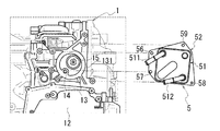
- FIG. 1A is an enlarged view of a main part for explaining the arrangement of the oil cooler 5 in the transmission case 1.
- FIG. 1B is a diagram illustrating a state in which the oil cooler 5 is removed from the transmission case 1. In FIG. 1B, hatches intersecting the oil holes 14 and 15 are added so that the positions of the oil holes 14 and 15 can be easily understood.
- a control valve CV accommodating portion 10 is provided below a transmission case 1 accommodating a transmission mechanism portion (not shown).
- the lower part of the accommodating portion 10 is open, and the lower opening of the accommodating portion 10 is closed by the oil pan 11.
- oil OL fluid
- the oil OL stored in the oil pan 11 is sucked through an oil strainer (not shown) attached to the control valve CV and supplied to the flood control circuit (not shown) in the control valve CV.
- the control valve CV regulates the pressure of the oil OL and supplies it to the transmission mechanism as hydraulic pressure for operation, while supplying a part of the sucked oil OL to the transmission mechanism to supply the rotating body, friction fastening element, etc. Lubricate and cool.
- the oil OL used for the operation, lubrication, and cooling of the transmission mechanism is returned to the oil pan 11 through the inner circumference of the transmission case 1 due to its own weight, and then is supplied to the control valve CV again. , Used for operation, lubrication, and cooling of transmission mechanisms.
- the transmission case 1 of the automatic transmission is provided with an oil cooler 5 for cooling the oil OL.
- the oil cooler 5 is provided by utilizing the accommodating portion 13 of the oil filter 4 (see FIG. 2B).
- the accommodating portion 13 is opened with an oil hole 14 serving as an oil outlet and an oil hole 15 serving as an oil inlet.
- the high-temperature oil discharged from the oil hole 14 is cooled by the oil cooler 5 and then returned to the flood control circuit side via the oil hole 15 and the oil passage in the transmission case 1. It has become.
- the accommodating portion 13 has a peripheral wall portion 131 that opens toward the outside of the transmission case 1.
- the peripheral wall portion 131 is provided close to the box portion 12 that houses the control device (ATCU) of the automatic transmission and the oil pump.
- the box portion 12 is formed so as to bulge from the outer periphery of the transmission case 1 toward the front side of the paper surface.
- the peripheral wall portion 131 is provided by utilizing the space on the side of the box portion 12, and the peripheral wall portion 131 is also formed so as to bulge toward the front side of the paper surface.
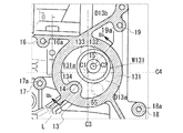
- FIG. 2A is an enlarged view of a region in which the oil cooler 5 is attached in the transmission case 1.
- FIG. 2B is a cross-sectional view of the accommodating portion 13 of the oil filter 4 cut along the line IIb-IIb in FIG. 2A.
- FIG. 2A in order to make it easy to understand the position of the surface related to the attachment of the oil cooler 5, the surface to which the base plate 52 of the oil cooler 5 is joined is shown with hatching.
- boss portions 16, 17, 18, 19 having bolt holes 16a, 17a, 18a, 19a are provided on the outside of the peripheral wall portion 131.
- the boss portions 16, 17, 18, and 19 are provided at intervals in the circumferential direction around the center line C1 of the peripheral wall portion 131 forming a circle when viewed from the opening direction of the peripheral wall portion 131.
- the boss portions 16, 17, 18, and 19 of the peripheral wall portion 131 are formed so as to project from the outer periphery of the transmission case 1 toward the front side of the paper surface.
- boss portions 16, 17, 18 and 19 are arranged one by one in each region. There is.
- a rib 134 having a substantially circular cross section is provided inside the peripheral wall portion 131.
- the rib 134 bulges from the inner circumference of the peripheral wall portion 131 toward the center line C1.
- the rib 134 is formed from the end surface 131b of the peripheral wall portion 131 to the entire length of the peripheral wall portion 131 in the height direction.
- An oil hole 14 is opened in the center of the rib 134.
- the oil hole 14 is provided along the longitudinal direction of the rib 134.
- the oil hole 14 communicates with a hydraulic control circuit (not shown) via an oil passage in the transmission case 1.
- the oil OL that has become hot by cooling the rotating body of the transmission mechanism and the like is supplied to the oil holes 14.
- the end surface 134b of the rib 134 is provided flush with the end surface 131b of the peripheral wall portion 131.
- the end surface 134b of the rib 134 and the end surface 131b of the peripheral wall portion 131 are joint surfaces with the base plate 52 (see FIG. 3B) of the oil cooler 5.
- a tubular wall portion 132 into which the oil filter 4 is fitted is provided on the side opposite to the rib 134 when viewed from the center line C1.
- a support wall portion 133 having an inner diameter larger than that of the cylinder wall portion 132 is provided concentrically with respect to the cylinder wall portion 132.
- An oil hole 15 is opened in the center of the cylinder wall portion 132.
- the oil hole 15 communicates with an oil passage (not shown) on the oil pressure control circuit side so that the oil OL that has passed through the oil filter 4 is returned to the oil pressure control circuit side (not shown) through the oil hole 15. It has become.
- the center line C2 of the tubular wall portion 132 is provided at a position offset from the center line C1 of the peripheral wall portion 131 to the peripheral wall portion 131 side (outer diameter side of the center line C1).
- the oil filter 4 fitted in the support wall portion 133 is arranged close to the inner circumference of the peripheral wall portion 131.
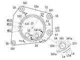
- FIG. 3A is a perspective view of the oil cooler 5 as viewed from the transmission case 1 side.
- FIG. 3B is a plan view of the base plate 52 of the oil cooler 5 as viewed from the transmission case 1 side.
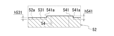
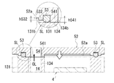
- FIG. 3C is a cross-sectional view of the base plate 52 cut along the line IIIc-IIIc in FIG. 3B. Note that FIG. 3C exaggerates the heights h531 and h541 of the inner annular wall portion 531 and the partition wall portion 541 protruding from the facing surface 52a in order to make it easier to understand the difference in height between the facing surfaces 52a. ..
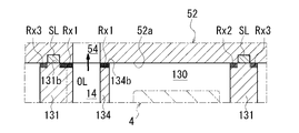
- FIG. 4A is a cross-sectional view of the base plate 52 cut along the line IVa-IVa in FIG. 3B.
- FIG. 4B is a cross-sectional view of the base plate 52 cut along the IVb-IVb line in FIG. 3B.
- H531, h532, and h541 are exaggerated.
- the oil cooler 5 is composed of a main body case 51 (case) in which a cooling water supply pipe 511 and a discharge pipe 512 are connected, and a base plate 52 provided on a surface of the main body case 51 facing the transmission case. ..
- the inside of the main body case 51 is a heat exchange portion in which the cooling water passage and the oil passage are arranged so that heat can be exchanged.
- the base plate 52 is a plate-shaped member having a size that covers the opening 131a (see FIG. 2A) of the peripheral wall portion 131 on the transmission case 1 side.
- the base plate 52 is made of a metal material having a hardness higher than that of the constituent material (aluminum alloy or the like) of the transmission case 1.
- Bolt holes 56, 57, 58, 59 are opened on the outer peripheral portion of the base plate 52.
- ring-shaped seating surfaces 561, 571, 581, 591 surrounding the bolt holes 56, 57, 58, 59 are provided.
- a ring groove 53 for accommodating the seal ring SL is provided on the facing surface 52a of the base plate 52.
- the ring groove 53 is provided in a region facing the peripheral wall portion 131 when the oil cooler 5 is assembled to the accommodating portion 13 of the oil filter 4 and fixed with the bolt B.
- the ring groove 53 is formed to have an inner diameter larger than the inner diameter D13a (see FIG. 2A) of the peripheral wall portion 131 and an outer diameter smaller than the outer diameter D13b (see FIG. 2A) of the peripheral wall portion 131.
- the inner annular wall portion 531 that surrounds the inner circumference of the ring groove 53 over the entire circumference and the outer annular wall portion 532 that surrounds the outer circumference of the ring groove 53 over the entire circumference are the paper surfaces in FIG. 3B. It is formed by bulging toward the front side.
- the height h531 of the inner annular wall portion 531 from the facing surface 52a is the same as the height h532 of the outer annular wall portion 532 from the facing surface 52a.
- the width W531 of the inner annular wall portion 531 in the radial direction of the center line C1 is the same as the width W532 of the outer annular wall portion 532 in the radial direction of the center line C1.
- the inner annular wall portion 531 and the outer annular wall portion 532 are formed with the same width W531 and 532, respectively, over the entire circumference in the circumferential direction around the center line C1.
- the width W52 from the inner circumference of the inner annular wall portion 531 to the outer circumference of the outer annular wall portion 532 is substantially the same as the radial width W131 of the peripheral wall portion 131 described above.
- the inflow port 54 of the oil OL and the discharge port 55 of the oil OL are opened at positions inscribed in the inner annular wall portion 531.
- the inflow port 54 is an inflow port of the oil OL to the heat exchange portion in the main body case 51 of the oil cooler 5.
- the discharge port 55 is a discharge port for oil OL cooled by the heat exchange section in the main body case 51.
- the inflow port 54 and the discharge port 55 are arranged close to each other on one side (lower side in FIG. 3B) of the diameter line L53 passing through the center of the ring groove 53.
- the discharge port 55 has a circular shape inscribed in the inner annular wall portion 531.
- the inflow port 54 has a circular shape having a size consistent with the oil hole 14 on the transmission case 1 side.
- the inflow port 54 is formed with an opening diameter slightly smaller than that of the discharge port 55.
- a partition wall portion 541 surrounding the inflow port 54 is formed on the facing surface 52a.
- the outer diameter side of the partition wall portion 541 when viewed from the center line C1 is formed so as to have a range overlapping with the inner annular wall portion 531.
- the height h541 of the partition wall portion 541 from the facing surface 52a is higher than the height h531 of the inner annular wall portion 531 from the facing surface 52a (see FIG. 3C).
- both side edges 541a and 541a in the circumferential direction around the center line C1 are formed in a straight line along the straight lines La and La. Both side edges 541a and 541a cross the inner annular wall portion 531 from the inner diameter side to the outer diameter side.
- the straight lines La and La are straight lines located symmetrically with a diameter line L54 passing through the center C54 of the inflow port 54 in between.
- the inner annular wall portion 531 and the outer annular wall portion 532 and the partition wall portion 541 of the facing surface 52a of the base plate 52 are formed by press molding.
- the inner annular wall portion 531 and the outer annular wall portion 532 and the partition wall portion 541 come into contact with the end surface 131b of the peripheral wall portion 131 forming the accommodating portion 13 of the oil filter 4 and the end surface 134b of the rib 134 inscribed in the peripheral wall portion 131. ..
- the peripheral wall portion 131 and the rib 134 on the transmission case 1 side are formed of an aluminum alloy, and the inner annular wall portion 531 and the outer annular wall portion 532 and the partition wall portion 541 are harder than the aluminum alloy. It is made of high metallic material. Therefore, the contact interface between the base plate 52 of the oil filter 4 and the peripheral rib 134 of the peripheral wall portion 131 is metal-sealed.
- the oil OL discharged from the discharge port 55 into the space inside the peripheral wall portion 131 is the end face 131b of the peripheral wall portion 131, the inner annular wall portion 531 and the outer annular wall portion 532. It becomes difficult to leak from the contact interface.
- the inflow port 54 on the oil cooler 5 side is arranged at a position overlapping the oil hole 14 (see FIG. 4B) on the transmission case 1 side, and the discharge port 55 on the oil cooler 5 side opens the peripheral wall portion 131. It is arranged at a position overlapping 131a (see FIG. 4A virtual line).
- the partition wall portion 541 surrounding the inflow port 54 is pressed against the end surface 134b of the rib 134 surrounding the oil hole 14 with a pressure corresponding to the fastening pressure of the bolt.
- the inner annular wall portion 531 on the inner diameter side of the ring groove 53 and the outer annular wall portion 532 on the outer diameter side are pressed against each other by the seal ring SL on the end surface 131b of the peripheral wall portion 131. Press contact is made between the inner diameter side and the outer diameter side of the formed region.
- the oil hole 14 and the inflow port 54 communicate with each other, and the contact interface between the rib 134 and the partition wall portion 541 of the base plate 52 is metal-sealed, so that the oil OL is less likely to leak from the contact interface. Therefore, it is possible to prevent the high-temperature oil OL flowing through the oil hole 14 from leaking from the contact interface between the rib 134 and the base plate 52 into the space 130 inside the peripheral wall portion 131 without flowing into the inflow port 54. As a result, it is possible to preferably prevent the oil OL from being returned from the oil hole 15 to the flood control circuit side without passing through the oil cooler 5.
- the oil hole 14 (outlet) on the transmission case 1 side and the inflow port 54 on the oil cooler 5 side are connected one-to-one between the base plate 52 on the oil cooler 5 side and the peripheral wall portion 131 on the transmission case 1 side. It is not necessary to separately arrange a plate component having a groove to be formed.
- the space 130 inside the peripheral wall portion 131 is sealed by the seal ring SL that is in pressure contact with the end surface 131b of the peripheral wall portion 131 and the metal touch areas Rx1, Rx2, and Rx3. Therefore, the oil OL is less likely to leak from the contact interface between the end surface 131b of the peripheral wall portion 131 and the base plate 52, as compared with the case where only the seal ring SL is pressed against the end surface 131b of the peripheral wall portion 131.
- FIGS. 6A to 8D are views for explaining the base plates 52A to 52L according to the modified example of the oil cooler 5.
- the inner annular wall portion 531 along the inner circumference of the ring groove 53, the outer annular wall portion 532 along the outer circumference, and the partition wall portion 541 surrounding the inflow port 54 are located on the transmission case 1 side from the facing surface 52a.
- the base plate 52 formed so as to project is illustrated.
- the partition wall portion 541 surrounding the inflow port 54 is pressed against the end surface 134b of the rib 134 on the transmission case 1 side to prevent oil OL from leaking from the contact interface between the base plate 52 and the rib 134. Therefore, the amount of oil OL flowing into the inflow port 54 was secured.
- the base plate 52 is not limited to this embodiment.
- the base plates 52A to 52H shown in FIGS. 6A-6D and 7A-7D may be used.
- the base plate 52A shown in FIG. 6A is provided with a ring-shaped partition wall portion 541A surrounding the inflow port 54 on the surface 52a facing the transmission case 1.
- the partition wall portion 541A is inscribed in the inner circumference of the ring groove 53.
- leakage of oil OL from the contact interface between the partition wall portion 541A on the facing surface 52a side and the peripheral edge of the oil hole 14 on the transmission case 1 side can be suitably suppressed, so that the oil OL can be suitably suppressed from the oil hole 14. It is possible to secure the inflow amount of the discharged oil OL to the inflow port 54.
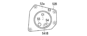
- the base plate 52B shown in FIG. 6B is provided with an arc-shaped partition wall portion 541B surrounding the peripheral region of the inflow port 54 protruding toward the front side of the paper surface on the surface 52a facing the transmission case 1.
- One end and the other end of the partition wall portion 541B reach the inner circumference of the ring groove 53. Therefore, when the base plate 52B is assembled to the transmission case 1, the seal ring SL housed in the ring groove 53 and the partition wall portion 541B form an annular wall surrounding the inflow port 54.
- a ring-shaped partition wall portion 551C surrounding the discharge port 55 is provided on the surface facing the transmission case 1 so as to bulge toward the front side of the paper surface, and the partition wall portion 551C is used for shifting. It is inserted inside the peripheral wall portion 131 on the machine case 1 side. In the case of the base plate 52C, the oil OL leaking from the contact interface between the facing surface 52a and the peripheral edge of the oil hole 14 on the transmission case 1 side to the inside of the peripheral wall portion 131 is difficult to reach the discharge port 55. ..
- the flow of the oil OL discharged from the inflow port 54 through the heat exchange portion and from the discharge port 55 is not obstructed by the oil OL leaking to the inside of the peripheral wall portion 131. If the distribution of oil OL from the discharge port 55 is hindered, the capacity of the heat exchange section is limited, which may hinder the inflow of oil OL into the inflow port 54. In the base plate 52C, the flow of the oil OL discharged from the discharge port 55 is not obstructed, and the inflow of the oil OL into the inflow port 54 is not hindered. Inflow amount can be secured.
- the base plate 52D shown in FIG. 6D is provided with an arc-shaped partition wall portion 551D surrounding the peripheral region of the discharge port 55 bulging toward the front side of the paper surface.
- One end and the other end of the partition wall portion 551D reach the inner circumference of the ring groove 53. Therefore, when the base plate 52D is assembled to the transmission case 1, the seal ring SL housed in the ring groove 53 and the partition wall portion 551D form an annular wall surrounding the discharge port 55.
- the oil OL leaking from the contact interface between the facing surface 52a and the peripheral edge of the oil hole 14 on the transmission case 1 side to the inside of the peripheral wall portion 131 is difficult to reach the discharge port 55. .. Therefore, the flow of the oil OL discharged from the inflow port 54 through the heat exchange portion and from the discharge port 55 is not significantly obstructed by the oil OL leaking to the inside of the peripheral wall portion 131. Therefore, for the reason described above, the oil OL flows from the oil hole 14. It is possible to secure the inflow amount of the discharged oil OL to the inflow port 54.
- a linear partition wall portion 521E is provided on the facing surface 52a with the transmission case 1 so as to bulge toward the front side of the paper surface.
- the partition wall portion 521E is provided across a straight line Lx connecting the centers of the inflow port 54 and the discharge port 55 to each other.
- the partition wall portion 521E extends along a straight line L passing through the center line C1 of the base plate 52E, and extends from the ring groove 53 to the vicinity of the center line C1 of the base plate 52E.
- a linear partition wall portion 521F is provided on the surface facing the transmission case 1 so as to bulge toward the front side of the paper surface.
- the partition wall portion 521F is provided across a straight line Lx connecting the centers of the inflow port 54 and the discharge port 55 to each other.
- the partition wall portion 521F extends along a straight line L passing through the center line C1 of the base plate 52E, and one end and the other end of the partition wall portion 521F in the longitudinal direction reach the ring groove 53, respectively.
- the partition walls 521E and 521F may be wavy or arcuate instead of linear.
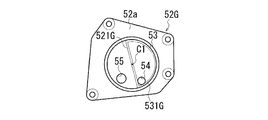
- a semicircular surrounding wall bulges toward the front side of the paper surface from the inner annular wall portion 531G along the inner circumference of the ring groove 53 and the linear partition wall portion 521G passing through the center line C1. It is formed, and the inflow port 54 is opened inside the surrounding wall.
- a semicircular surrounding wall bulges toward the front side of the paper surface from the inner annular wall portion 531H along the inner circumference of the ring groove 53 and the linear partition wall portion 521H passing through the center line C1. It is formed, and the discharge port 55 is opened inside the surrounding wall.
- the partition wall portion 541A is projected from the surface 52a facing the transmission case 1. Therefore, when only the partition wall portion 541A is provided on the facing surface 52a, the oil cooler 5 may tilt with the partition wall portion 541A as a fulcrum.
- an arc-shaped wall portion 531I along the inner circumference of the ring groove 53 is provided on the side opposite to the partition wall portion 541A when viewed from the center line C1.
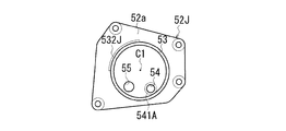
- an arc-shaped wall portion 532J along the outer periphery of the ring groove 53 is provided on the side opposite to the partition wall portion 541A when viewed from the center line C1.
- an arcuate wall portion 531K is provided at a position offset from the ring groove 53 to the inner diameter side on the side opposite to the partition wall portion 541A when viewed from the center line C1.
- an arc-shaped wall portion 532L is provided at a position offset from the ring groove 53 to the outer diameter side on the side opposite to the partition wall portion 541A when viewed from the center line C1.
- the oil cooler 5 can be suitably prevented from tilting by providing the arc-shaped wall portions 531I, 513K, 532J, and 532L separately from the partition wall portion 541A.
- these arc-shaped wall portions 531I, 513K, 532J, 532L may be used in any combination.
- the oil cooler 5 has the following configuration.
- the oil cooler 5 (device) is A main body case 51 (case) having a heat exchange part and The inflow port 54 of the oil OL (fluid) to the heat exchange part, It has an oil OL discharge port 55 from the heat exchange section.
- the inflow port 54 and the discharge port 55 are opened on the surface 52a facing the transmission case 1 to which the oil cooler 5 is assembled.
- the inflow port 54 is arranged to face the oil hole 14 which is the fluid outlet on the transmission case 1 side.
- a partition wall portion 541 (bulkhead) for partitioning the inflow port 54 side and the discharge port 55 side is provided on the facing surface 52a so as to project toward the transmission case 1 side.
- the partition wall portion 541 obstructs the flow of oil OL toward the discharge port 55 side without flowing into the inflow port 54 on the facing surface 52a. As a result, more oil OL can flow into the inflow port 54 and be supplied to the heat exchange section side, so that the oil OL can be appropriately cooled. Further, since the partition wall portion 541 can be easily formed by press molding, more oil OL can flow into the heat exchange portion side with an inexpensive configuration.
- the device is not limited to the oil cooler 5.
- the target also includes a power transmission device that transmits the output rotation of a drive source (engine, motor) and a conventionally known automatic transmission that is provided with a heat exchange unit for cooling the oil OL. Further, the power transmission device may or may not be provided with a speed change mechanism for shifting the transmitted rotation.
- partition wall that separates the inflow port 54 side and the discharge port 55 side may be as follows.
- the base plate 52E is provided from the ring groove 53 along the straight line L passing through the center line C1 of the base plate 52E while being provided across the straight line Lx connecting the centers of the inflow port 54 and the discharge port 55 to each other.
- a partition wall portion 521E (see FIG. 7A) formed so as to extend to the vicinity of the center line C1.
- a partition wall portion 521F that is provided across a straight line Lx that connects the centers of the inflow port 54 and the discharge port 55 to each other and extends along a straight line L that passes through the center line C1 of the base plate 52E.
- the partition wall is one of the following.
- a partition wall portion 541B provided around the inflow port 54 (see FIG. 6B).
- B) A partition wall portion 551D provided around the discharge port 55 (see FIG. 6D).
- Surrounding wall see Fig. 7C
- D A semi-circular surrounding wall formed of an inner annular wall portion 531H along the inner circumference of the ring groove 53 and a linear partition wall portion 521H passing through the center line C1, and the discharge port 55 is opened inside. Surrounding wall (see Fig. 7D).
- partition walls are partition walls 541 and 541A provided so as to surround the inflow port 54 (see FIGS. 3B and 6A).
- the partition wall is provided only around the discharge port 55, the movement of the oil OL from the inflow port 54 side to the discharge port 55 side can be suppressed, but the inflow amount of the oil OL discharged from the oil hole 14 to the inflow port 54 can be suppressed. It cannot be prevented from decreasing.
- the partition wall portion 541 so as to surround the inflow port 54, it is possible to secure the inflow amount of the oil OL discharged from the oil hole 14 into the inflow port 54.
- the partition walls 541 and 541A have a cylindrical shape surrounding the inflow port 54, and the partition walls 541 and 541A are oil holes which are fluid outlets when the oil cooler 5 is assembled to the transmission case 1.
- a metal touch region is formed by pressure contacting the peripheral edge of 14 over the entire circumference.
- leakage of oil OL from the contact interface between the partition walls 541 and 541A on the facing surface 52a side and the peripheral edge of the oil hole 14 on the transmission case 1 side can be suitably suppressed, so that the oil OL can be suitably suppressed from the oil hole 14. It is possible to secure the inflow amount of the discharged oil OL to the inflow port 54. Further, with an inexpensive configuration, leakage of oil OL from the contact interface can be suitably suppressed.
- a support wall (inner annular wall portion 531, outer annular wall portion 531) for preventing the oil cooler 5 from tilting with the partition wall portion 541 as a fulcrum is provided on the surface 52a of the base plate 52 of the oil cooler 5 facing the transmission case 1.
- a wall portion 532) is further provided. The inner annular wall portion 531 and the outer annular wall portion 532 project from the facing surface 52a toward the transmission case 1.
- the oil cooler 5 may tilt with the partition wall portion 541 as a fulcrum.
- a support wall inner annular wall portion 531 and outer annular wall portion 532 separately from the partition wall portion 541, it is possible to preferably prevent the oil cooler 5 from tilting.
- the support wall does not necessarily have to be annular, and may be the following support wall.
- A An arcuate wall portion 531I provided along the inner circumference of the ring groove 53 on the side opposite to the partition wall portion 541A when viewed from the center line C1 (see FIG. 8A).
- B An arc-shaped wall portion 532J provided along the outer circumference of the ring groove 53 on the side opposite to the partition wall portion 541A when viewed from the center line C1 (see FIG. 8B).
- C An arc-shaped wall portion 531K provided at a position offset from the ring groove 53 to the inner diameter side on the side opposite to the partition wall portion 541A when viewed from the center line C1 (see FIG. 8C).
- the shape of the support wall portion does not have to be an arc-shaped wall portion, and may be linear or wavy.
- a ring groove 53 for accommodating the seal ring SL is provided on the surface 52a of the main body case 51 of the oil cooler 5 facing the transmission case 1.
- the support wall is at least one of an inner annular wall portion 531 along the inner circumference of the ring groove 53 and an outer annular wall portion 532 along the outer circumference of the ring groove 53.
- the partition wall portion 541 is provided inside the ring groove 53.
- the oil cooler 5 may tilt with the partition wall portion 541 as a fulcrum. If the oil cooler 5 is tilted, the sealing performance of the sealing ring SL may be affected. With the above configuration, the support wall can prevent the oil cooler 5 from tilting, so that it is possible to preferably prevent the oil OL from leaking to the outside of the seal ring SL due to the tilting of the oil cooler 5. ..
- the inflow port 54 is opened at a position close to the ring groove, and the partition wall portion 541 is not provided at a position closer to the center of the ring groove (a position closer to the center line C1). Therefore, the partition wall portion 541 protruding from the facing surface 52a makes it easier for the oil cooler 5 to tilt. Therefore, by providing the inner annular wall portion 531 and / or the outer annular wall portion 532, the inclination of the oil cooler 5 is more preferably prevented. can.
- the height h541 of the partition wall portion 541 from the facing surface 52a is higher than the heights h531 and h532 of the support wall (inner annular wall portion 531 and outer annular wall portion 532) from the facing surface 52a.
- the metal touch region Rx1 caused by the partition wall portion 541 is surely formed at the contact interface between the base plate 52 and the peripheral wall portion 131.
- the oil hole 14 and the inflow port 54 are appropriately communicated with each other to allow more oil OL to flow. It can flow into the entrance 54.
- the present invention can also be specified as an assembly structure of the oil cooler 5 for an automatic transmission (a component to which the device is assembled).
- an oil hole 14 serving as a fluid outlet and an oil hole 15 serving as a fluid inlet are opened inside the peripheral wall portion 131, which is an area to which an oil cooler (heat exchange device) is assembled.
- Oil cooler 5 A main body case 51 having a heat exchange section and It has an oil OL (fluid) inflow port 54 to the heat exchange section, and a base plate 52 having an oil OL discharge port from the heat exchange section. In the base plate 52, the inflow port 54 and the discharge port 55 are opened on the surface 52a facing the transmission case 1.
- the inflow port 54 is arranged to face the oil hole 14 which is the fluid outlet on the transmission case 1 side.
- a partition wall portion 541 surrounding the inflow port 54 is formed so as to bulge toward the transmission case 1, and the inflow port 54 side and the discharge port 55 side of the facing surface 52a are partitioned.
- the partition wall portion 541 is pressed against the peripheral edge portion of the oil hole 14 to form a metal touch region.
Landscapes
- Engineering & Computer Science (AREA)
- Mechanical Engineering (AREA)
- General Engineering & Computer Science (AREA)
- Physics & Mathematics (AREA)
- Thermal Sciences (AREA)
- General Details Of Gearings (AREA)
- Lubrication Of Internal Combustion Engines (AREA)
- Heat-Exchange Devices With Radiators And Conduit Assemblies (AREA)
Abstract
Description
自動変速機のオイルの冷却に用いる場合には、オイルクーラは、変速機ケースの外周に付設される。
変速機ケースの外周には、オイルの出口と入口が開口しており、オイルクーラにおける変速機ケースとの対向部には、オイルの流入口と排出口が開口している。
JP5161709Bでは、変速機ケース側の出口から排出されたオイルが、オイルクーラを通らずに、変速機ケース側の入口に流入することを防ぐために、以下のような構成を採用している。
そのため、より簡単な構成で、より多くのオイル(流体)をオイルクーラ(熱交換装置)に流入させることが求められている。
熱交換部を有するケースと、
前記熱交換部への流体の流入口と、
前記熱交換部からの前記流体の排出口と、を有する装置であって、
前記ケースでは、前記装置が組み付けられる部品との対向面に、前記流入口と前記排出口が開口しており、
前記流入口は、前記部品の流体出口に対向配置されており、
前記対向面に、前記流入口側と前記排出口側とを区画する隔壁が設けられている装置が提供される。
収容部10の下部は開口しており、収容部10の下部開口は、オイルパン11により塞がれている。オイルパン11の内部には、変速機構部などの作動や潤滑、そして冷却などに用いられるオイルOL(流体)が貯留されている。
コントロールバルブCVは、オイルOLを調圧して変速機構部などに作動用の油圧として供給する一方で、吸引したオイルOLの一部を変速機構部などに供給して、回転体や摩擦締結要素などを潤滑、冷却する。
オイルクーラ5は、オイルフィルタ4(図2B参照)の収容部13を利用して設けられている。収容部13には、オイルの出口となる油孔14と、オイルの入口となる油孔15が開口している。
自動変速機では、油孔14から排出された高温のオイルが、オイルクーラ5で冷却されたのちに、油孔15と変速機ケース1内の油路を介して油圧制御回路側に戻されるようになっている。
箱部12は、変速機ケース1の外周から紙面手前側に膨出して形成されている。周壁部131は、箱部12の側方の空間を利用して設けられており、周壁部131もまた、紙面手前側に膨出して形成されている。
なお、図2Aでは、オイルクーラ5の取り付けに関わる面の位置を判り易くするために、オイルクーラ5のベースプレート52が接合される面にハッチングを付して示している。
周壁部131の開口方向から見てボス部16、17、18、19は、円形を成す周壁部131の中心線C1周りの周方向に、間隔をあけて設けられている。
中心線C1に直交すると共に互いに直交する直線C3、C4を基準として、周壁部131の外側を4つの領域に区画すると、各領域に1つずつボス部16、17、18、19が配置されている。
図2Bに示すように、リブ134は、周壁部131の端面131bから、周壁部131の高さ方向の全長に亘って形成されている。
リブ134の端面134bと周壁部131の端面131bは、オイルクーラ5のベースプレート52(図3B参照)との接合面となっている。
筒壁部132の外側には、筒壁部132よりも内径が大きい支持壁部133が、筒壁部132に対して同心に設けられている。
なお、図4A、図4Bでは、対向面52aでの高さの違いを判り易くするために、対向面52aから突出する内側環状壁部531と、外側環状壁部532と、隔壁部541の高さh531、h532、h541を誇張して示している。
本体ケース51の内部は、冷却水の通流路とオイルの通流路とが熱交換可能に配置された熱交換部となっている。
ベースプレート52における変速機ケース1との対向面52aでは、ボルト孔56、57、58、59を囲むリング状の着座面561、571、581、591が設けられている。
これにより、ボルト孔56、57、58、59を貫通して、ボス部16、17、18、19のボルト孔16a、17a、18a、19aに螺入したボルトBの締結圧が、ボス部16、17、18、19に略均等に作用する。
リング溝53は、オイルクーラ5をオイルフィルタ4の収容部13に組み付けてボルトBで固定した際に、前記した周壁部131に対向する領域に設けられている。
リング溝53は、周壁部131の内径D13a(図2A参照)よりも大きい内径、かつ、周壁部131の外径D13b(図2A参照)よりも小さい外径で形成されている。
よって、オイルクーラ5側のベースプレート52と、変速機ケース1側の周壁部131との接合面から、周壁部131の内側のオイルOLが漏出しないようになっている。
図4Aに示すように、内側環状壁部531の対向面52aからの高さh531は、外側環状壁部532の対向面52aからの高さh532と同じである。
さらに、中心線C1の径方向における内側環状壁部531の幅W531は、中心線C1の径方向における外側環状壁部532の幅W532と同じである。
内側環状壁部531の内周から外側環状壁部532外周までの幅W52は、前記した周壁部131の径方向の幅W131と略同じである。
流入口54は、オイルクーラ5の本体ケース51内の熱交換部へのオイルOLの流入口である。排出口55は、本体ケース51内の熱交換部で冷却されたオイルOLの排出口である。
排出口55は、内側環状壁部531に内接する円形を成している。流入口54は、前記した変速機ケース1側の油孔14と整合する大きさの円形を成している。流入口54は、排出口55よりも僅かに小さい開口径で形成されている。
隔壁部541の対向面52aからの高さh541は、内側環状壁部531の対向面52aからの高さh531よりも高くなっている(図3C参照)。
直線La、Laは、流入口54の中心C54を通る直径線L54を間に挟んで対称に位置する直線である。
内側環状壁部531および外側環状壁部532と、隔壁部541は、オイルフィルタ4の収容部13を形成する周壁部131の端面131bと、周壁部131に内接するリブ134の端面134bに接触する。
そのため、オイルフィルタ4のベースプレート52と、周壁部131およりリブ134との接触界面がメタルシールされる。
変速機ケース1にオイルクーラ5を組み付ける際には、ボス部16、17、18、19のボルト孔16a、17a、18a、19a(図2A参照)に、ベースプレート52のボルト孔56、57、58、59(図1B参照)が重なるようにして、変速機ケース1の周壁部131に、オイルクーラ5が重ねられる。
この状態で、ボルト孔56、57、58、59(図3B参照)を貫通して、ボス部16、17、18、19のボルト孔16a、17a、18a、19a(図2A参照)に螺入したボルトBを締め付ける。
さらにボルトを締め付けると、図4Aに示すように、リング溝53の内径側の内側環状壁部531と、外径側の外側環状壁部532が、周壁部131の端面131bにおけるシールリングSLが圧接した領域の内径側と外径側とに圧接する。
よって油孔14を流れる高温のオイルOLが、流入口54に流入せずに、リブ134とベースプレート52との接触界面から、周壁部131の内側の空間130に漏出することを防止できる。これにより、オイルOLが、オイルクーラ5を通らずに、油孔15から油圧制御回路側に戻されることを好適に防止できる。
オイルクーラ5側のベースプレート52と変速機ケース1側の周壁部131との間に、変速機ケース1側の油孔14(出口)とオイルクーラ5側の流入口54とを1対1で接続する溝を有するプレート部品を別途配置する必要もない。
前記した実施形態では、リング溝53の内周に沿う内側環状壁部531と外周に沿う外側環状壁部532と、流入口54を囲む隔壁部541とが、対向面52aから変速機ケース1側に突出して形成されたベースプレート52を例示した。
このベースプレート52では、流入口54を囲む隔壁部541が、変速機ケース1側のリブ134の端面134bに圧接することで、ベースプレート52とリブ134との接触界面からのオイルОLの漏出を阻止して、流入口54に流入するオイルОLの量を確保していた。
図6Aに示すベースプレート52Aは、変速機ケース1との対向面52aに、流入口54を囲むリング状の隔壁部541Aが設けられている。隔壁部541Aは、リング溝53の内周に内接している。
ベースプレート52Aを変速機ケース1に組み付けると、隔壁部541Aが、変速機ケース1側の油孔14の周縁に全周に亘って圧接して、メタルタッチ領域を形成する。
このベースプレート52Aの場合にも、対向面52a側の隔壁部541Aと、変速機ケース1側の油孔14の周縁との接触界面からのオイルOLの漏出を好適に抑制できるので、油孔14から排出されたオイルOLの流入口54への流入量を確保できる。
そのため、ベースプレート52Bを変速機ケース1に組み付けると、リング溝53に収容されたシールリングSLと隔壁部541Bで、流入口54を囲む環状壁が形成される。
接触界面から漏出したオイルOLの流れが妨げられると、接触界面から漏出するオイルの総量もまた抑制されるので、油孔14から排出されたオイルOLの流入口54への流入量を確保できる。
ベースプレート52Cの場合には、対向面52aと、変速機ケース1側の油孔14の周縁との接触界面から周壁部131の内側に漏出したオイルOLが、排出口55に到達し難くなっている。
そのため、流入口54から熱交換部を通って排出口55から排出されるオイルOLの流れが、周壁部131の内側に漏出したオイルOLにより阻害されない。排出口55からのオイルOLの配収が阻害されると、熱交換部の容量が限られていることから、流入口54へのオイルОLの流入に支障が生ずる可能性がある。
ベースプレート52Cでは、排出口55から排出されるオイルOLの流れが阻害されず、流入口54へのオイルОLの流入に支障が生じないので、油孔14から排出されたオイルOLの流入口54への流入量を確保できる。
そのため、ベースプレート52Dを変速機ケース1に組み付けると、リング溝53に収容されたシールリングSLと隔壁部551Dで、排出口55を囲む環状壁が形成される。
そのため、流入口54から熱交換部を通って排出口55から排出されるオイルOLの流れが、周壁部131の内側に漏出したオイルOLにより大きく阻害されないので、前記した理由により、油孔14から排出されたオイルOLの流入口54への流入量を確保できる。
なお、前記した隔壁部521E、521Fは、直線状でなく波状や弧状であっても良い。
そのため、流入口54から熱交換部を通って排出口55から排出されるオイルOLの流れが、周壁部131の内側に漏出したオイルOLにより大きく阻害されないので、前記した理由により、油孔14から排出されたオイルOLの流入口54への流入量を確保できる。
図8Aに示すベースプレート52Iでは、中心線C1から見て、隔壁部541Aとは反対側に、リング溝53の内周に沿う弧状壁部531Iが設けられている。
図8Bに示すベースプレート52Jでは、中心線C1から見て、隔壁部541Aとは反対側に、リング溝53の外周に沿う弧状壁部532Jが設けられている。
図8Cに示すベースプレート52Kでは、中心線C1から見て、隔壁部541Aとは反対側に、リング溝53から内径側にオフセットした位置に弧状壁部531Kが設けられている。
図8Dに示すベースプレート52Lでは、中心線C1から見て、隔壁部541Aとは反対側に、リング溝53から外径側にオフセットした位置に弧状壁部532Lが設けられている。
なお、これら弧状壁部531I、531K、532J、532Lは、任意に組み合わせて用いても良い。
(1)オイルクーラ5(装置)は、
熱交換部を有する本体ケース51(ケース)と、
熱交換部へのオイルOL(流体)の流入口54と、
熱交換部からのオイルOLの排出口55と、を有する。
本体ケース51では、オイルクーラ5が組み付けられる変速機ケース1との対向面52aに、流入口54と排出口55が開口している。
流入口54は、変速機ケース1側の流体出口である油孔14に対向配置されている。
対向面52aに、流入口54側と排出口55側とを区画する隔壁部541(隔壁)が、変速機ケース1側に突出して設けられている。
また、動力伝達装置は、伝達される回転を変速する変速機構を備えているものであっても、備えていないものであってもよい。
(a)流入口54と排出口55の互いの中心同士を結ぶ直線Lxを横切って設けられていると共に、ベースプレート52Eの中心線C1を通る直線Lに沿って、リング溝53から、ベースプレート52Eの中心線C1の近傍まで及んで形成された隔壁部521E(図7A参照)。
(b)流入口54と排出口55の互いの中心同士を結ぶ直線Lxを横切って設けられていると共に、ベースプレート52Eの中心線C1を通る直線Lに沿って延びる隔壁部521F。隔壁部521Fの長手方向の一端と他端は、それぞれリング溝まで達している(図7B参照)。
このように構成すると、流入口54に流入せずに排出口55側に向かうオイルOLの流れが、隔壁部521E、521Fで妨げられるので、より多くのオイルOLを流入口54に流入させて、熱交換部側に供給できる。
(a)流入口54の周辺に設けられた隔壁部541B(図6B参照)。
(b)排出口55の周辺に設けられた隔壁部551D(図6D参照)。
(c)リング溝53の内周に沿う内側環状壁部531Gと、中心線C1を通る直線状の隔壁部521Gとから形成された半円形の囲繞壁であって、内側に流入口54が開口している囲繞壁(図7C参照)。
(d)リング溝53の内周に沿う内側環状壁部531Hと、中心線C1を通る直線状の隔壁部521Hとから形成された半円形の囲繞壁であって、内側に排出口55が開口している囲繞壁(図7D参照)。
隔壁部541を、流入口54を囲むように設けることで、油孔14から排出されたオイルOLの流入口54への流入量を確保できる。
また、安価な構成で、接触界面からのオイルOLの漏出を好適に抑制できる。
内側環状壁部531と外側環状壁部532は、対向面52aから変速機ケース1側に突出している。
隔壁部541とは別に、支持壁(内側環状壁部531、外側環状壁部532)を別途設けることで、オイルクーラ5が傾くことを好適に防止できる。
(a)中心線C1から見て、隔壁部541Aとは反対側に、リング溝53の内周に沿って設けられた弧状壁部531I(図8A参照)。
(b)中心線C1から見て、隔壁部541Aとは反対側に、リング溝53の外周に沿って設けられた弧状壁部532J(図8B参照)。
(c)中心線C1から見て、隔壁部541Aとは反対側に、リング溝53から内径側にオフセットした位置に設けられた弧状壁部531K(図8C参照)。
(d)中心線C1から見て、隔壁部541Aとは反対側に、リング溝53から外径側にオフセットした位置に設けられた弧状壁部532L(図8D参照)。
(e)(a)から(d)の弧状壁部の任意の組み合わせ。
なお、支持壁部の形状は、弧状壁部である必要は無く、直線状や波状であっても良い。
支持壁は、リング溝53の内周に沿う内側環状壁部531と、リング溝53の外周に沿う外側環状壁部532のうちの少なくとも一方である。
隔壁部541は、リング溝53の内側に設けられている。
特に、流入口54は、リング溝に近接した位置に開口しており、隔壁部541は、リング溝の中央寄りの位置(中心線C1寄りの位置)に設けられていない。よって、対向面52aから突出する隔壁部541により、オイルクーラ5が傾きやすくなるので、内側環状壁部531および/または外側環状壁部532を設けることで、オイルクーラ5の傾きをより好適に阻止できる。
自動変速機の変速機ケース1では、オイルクーラ(熱交換装置)が組み付けられる領域である周壁部131の内側に、流体出口となる油孔14と、流体入口となる油孔15が開口している。
オイルクーラ5は、
熱交換部を有する本体ケース51と、
熱交換部へのオイルOL(流体)の流入口54、および熱交換部からのオイルOLの排出口と、を有するベースプレート52と、を有している。
ベースプレート52では、変速機ケース1との対向面52aに、流入口54と排出口55が開口している。
流入口54は、変速機ケース1側の流体出口である油孔14に対向配置されている。
対向面52aには、流入口54を囲む隔壁部541が変速機ケース1側に膨出して形成されて、対向面52aにおける流入口54側と排出口55側とが区画されている。
隔壁部541は、オイルクーラ5を周壁部131に組み付けた際に、油孔14の周縁部に圧接してメタルタッチ領域を形成する。
このように構成すると、対向面52a側の隔壁部541と、変速機ケース1側の油孔14の周縁部との接触界面からのオイルOLの漏出を好適に抑制できるので、油孔14から排出されたオイルOLの流入口54への流入量を確保できる。
Claims (7)
- 熱交換部を有するケースと、
前記熱交換部への流体の流入口と、
前記熱交換部からの前記流体の排出口と、を有する装置であって、
前記ケースでは、前記装置が組み付けられる部品との対向面に、前記流入口と前記排出口が開口しており、
前記流入口は、前記部品の流体出口に対向配置されており、
前記対向面に、前記流入口側と前記排出口側とを区画する隔壁が設けられている、
装置。 - 前記隔壁は、前記流入口または前記排出口の周辺に設けられている、
請求項1に記載の装置。 - 前記隔壁は、前記流入口を囲むように設けられている、
請求項1に記載の装置。 - 前記隔壁は、前記流入口を囲む筒状を成しており、前記隔壁は、前記装置を前記部品に組み付けた際に、前記流体出口の周縁に全周に亘って圧接する、
請求項1に記載の装置。 - 前記ケースにおける前記部品との対向面には、前記隔壁を支点とした前記ケースの傾きを阻止するための支持壁がさらに設けられている、
請求項2から請求項4の何れか一項に記載の装置。 - 前記ケースにおける前記部品との対向面には、シールリングを収容するリング溝が設けられており、
前記支持壁は、前記リング溝の内周に沿う内側環状壁と、前記リング溝の外周に沿う外側環状壁のうちの少なくとも一方であり、
前記隔壁は、前記リング溝の内側に設けられている、
請求項5に記載の装置。 - 前記隔壁は、前記対向面からの前記支持壁の高さよりも高い、
請求項6に記載の装置。
Priority Applications (3)
| Application Number | Priority Date | Filing Date | Title |
|---|---|---|---|
| CN202180022189.2A CN115298508A (zh) | 2020-03-16 | 2021-02-24 | 装置 |
| JP2022508161A JP7360540B2 (ja) | 2020-03-16 | 2021-02-24 | 装置 |
| US17/910,254 US12050069B2 (en) | 2020-03-16 | 2021-02-24 | Heat exchange apparatus for cooling oil |
Applications Claiming Priority (2)
| Application Number | Priority Date | Filing Date | Title |
|---|---|---|---|
| JP2020045880 | 2020-03-16 | ||
| JP2020-045880 | 2020-03-16 |
Publications (1)
| Publication Number | Publication Date |
|---|---|
| WO2021187026A1 true WO2021187026A1 (ja) | 2021-09-23 |
Family
ID=77771972
Family Applications (1)
| Application Number | Title | Priority Date | Filing Date |
|---|---|---|---|
| PCT/JP2021/006772 Ceased WO2021187026A1 (ja) | 2020-03-16 | 2021-02-24 | 装置 |
Country Status (4)
| Country | Link |
|---|---|
| US (1) | US12050069B2 (ja) |
| JP (1) | JP7360540B2 (ja) |
| CN (1) | CN115298508A (ja) |
| WO (1) | WO2021187026A1 (ja) |
Citations (4)
| Publication number | Priority date | Publication date | Assignee | Title |
|---|---|---|---|---|
| US20100206516A1 (en) * | 2007-11-06 | 2010-08-19 | Mueller-Lufft Stefan | Heat exchanger, particularly an oil cooler |
| WO2012104077A1 (en) * | 2011-02-01 | 2012-08-09 | Reinz-Dichtungs-Gmbh | Heat exchanger |
| JP2015004468A (ja) * | 2013-06-20 | 2015-01-08 | 株式会社マーレ フィルターシステムズ | オイルクーラ |
| JP2019148245A (ja) * | 2018-02-28 | 2019-09-05 | トヨタ自動車株式会社 | オイルクーラ |
Family Cites Families (27)
| Publication number | Priority date | Publication date | Assignee | Title |
|---|---|---|---|---|
| BE794794A (fr) | 1971-11-04 | 1973-05-16 | Modine Mfg Cy | Appareil echangeur de chaleur |
| US4360055A (en) | 1976-09-08 | 1982-11-23 | Modine Manufacturing Company | Heat exchanger |
| JPS6293414A (ja) * | 1985-10-18 | 1987-04-28 | Honda Motor Co Ltd | オイルフイルタ装置 |
| JPS63134268U (ja) * | 1987-02-13 | 1988-09-02 | ||
| JPH0684179U (ja) | 1993-05-11 | 1994-12-02 | 東京濾器株式会社 | オイルクーラ装置 |
| US5797450A (en) | 1996-05-02 | 1998-08-25 | Honda Giken Kogyo Kabushiki Kaisha | Oil cooler for automobiles |
| JP2807873B2 (ja) | 1996-05-02 | 1998-10-08 | 本田技研工業株式会社 | 自動車用オイルクーラ |
| JP2000204920A (ja) | 1998-11-13 | 2000-07-25 | Denso Corp | オイルク―ラの取付構造 |
| DE69914287T2 (de) | 1998-11-13 | 2004-11-18 | Denso Corp., Kariya | Befestigungsvorrichtung für Ölkühler |
| DE10005889A1 (de) * | 2000-02-10 | 2001-08-16 | Mann & Hummel Filter | Flüssigkeitskühlersystem |
| JP4519362B2 (ja) * | 2001-05-10 | 2010-08-04 | 株式会社マーレ フィルターシステムズ | フィルタ一体型オイルクーラ |
| US6450252B1 (en) * | 2001-08-15 | 2002-09-17 | Lih Yann Co., Ltd. | Oil changing unit having heat exchanger |
| CN1275016C (zh) * | 2002-06-10 | 2006-09-13 | 清华大学 | 一种多通道闭式外融冰蓄冰槽 |
| JP2004060974A (ja) | 2002-07-29 | 2004-02-26 | Calsonic Kansei Corp | オイルク−ラ |
| JP2004278985A (ja) * | 2003-03-18 | 2004-10-07 | Denso Corp | 熱交換器 |
| JP2005042991A (ja) * | 2003-07-23 | 2005-02-17 | Denso Corp | オイルクーラ |
| JP4211531B2 (ja) * | 2003-08-06 | 2009-01-21 | マツダ株式会社 | パワートレーンの制振装置 |
| DE10347181B4 (de) * | 2003-10-10 | 2005-12-22 | Modine Manufacturing Co., Racine | Wärmetauscher, insbesondere Ölkühler |
| JP5161709B2 (ja) | 2008-09-02 | 2013-03-13 | 株式会社マーレ フィルターシステムズ | オイルクーラ |
| US8911620B2 (en) * | 2010-11-29 | 2014-12-16 | Vesa S. Silegren | Universal spin-on oil filter adapter |
| JP6122266B2 (ja) * | 2012-08-27 | 2017-04-26 | 株式会社マーレ フィルターシステムズ | 熱交換器 |
| BR102013017090A2 (pt) * | 2013-07-02 | 2015-06-30 | Mahle Metal Leve Sa | Trocador de calor para alimentação de combustível em motores de combustão interna |
| JP2017116135A (ja) | 2015-12-22 | 2017-06-29 | 株式会社マーレ フィルターシステムズ | オイルクーラのオイルバイパス構造 |
| JP6671170B2 (ja) * | 2015-12-28 | 2020-03-25 | 株式会社マーレ フィルターシステムズ | 熱交換器 |
| CN205779088U (zh) * | 2016-06-11 | 2016-12-07 | 潍柴动力股份有限公司 | 机油冷却器基础总成 |
| JP2018194281A (ja) * | 2017-05-22 | 2018-12-06 | カルソニックカンセイ株式会社 | 熱交換器 |
| DE102020203892A1 (de) * | 2019-03-29 | 2020-10-01 | Dana Canada Corporation | Tauschermodul mit einem adaptermodul zum direkten anbau an einer fahrzeugkomponente |
-
2021
- 2021-02-24 CN CN202180022189.2A patent/CN115298508A/zh active Pending
- 2021-02-24 JP JP2022508161A patent/JP7360540B2/ja active Active
- 2021-02-24 WO PCT/JP2021/006772 patent/WO2021187026A1/ja not_active Ceased
- 2021-02-24 US US17/910,254 patent/US12050069B2/en active Active
Patent Citations (4)
| Publication number | Priority date | Publication date | Assignee | Title |
|---|---|---|---|---|
| US20100206516A1 (en) * | 2007-11-06 | 2010-08-19 | Mueller-Lufft Stefan | Heat exchanger, particularly an oil cooler |
| WO2012104077A1 (en) * | 2011-02-01 | 2012-08-09 | Reinz-Dichtungs-Gmbh | Heat exchanger |
| JP2015004468A (ja) * | 2013-06-20 | 2015-01-08 | 株式会社マーレ フィルターシステムズ | オイルクーラ |
| JP2019148245A (ja) * | 2018-02-28 | 2019-09-05 | トヨタ自動車株式会社 | オイルクーラ |
Also Published As
| Publication number | Publication date |
|---|---|
| CN115298508A (zh) | 2022-11-04 |
| US12050069B2 (en) | 2024-07-30 |
| US20240027145A1 (en) | 2024-01-25 |
| JPWO2021187026A1 (ja) | 2021-09-23 |
| JP7360540B2 (ja) | 2023-10-12 |
Similar Documents
| Publication | Publication Date | Title |
|---|---|---|
| JP2020101291A (ja) | 弁装置 | |
| EP1083371B1 (en) | Cylinder head gasket with gas releasing portion | |
| JP2002502945A (ja) | 内燃エンジン用のシリンダヘッドガスケット | |
| EP1923561B1 (en) | Gasket with leak conduit | |
| JP6995833B2 (ja) | 制御バルブ | |
| JP7331646B2 (ja) | バルブ装置 | |
| JP2021004670A (ja) | バルブ装置 | |
| JPH03181656A (ja) | 駆動装置 | |
| JP7360540B2 (ja) | 装置 | |
| JP7400614B2 (ja) | バルブ装置 | |
| CN105408553A (zh) | 箱体的冷却液排出结构、蓄电装置以及工程机械 | |
| WO2023182446A1 (ja) | 動力伝達装置 | |
| WO2023199894A1 (ja) | 冷却器 | |
| JP2014500927A (ja) | ロータリーピストン機械、特にロータリーエンジン | |
| EP3499097B1 (en) | Seal ring and seal structure | |
| JP7110620B2 (ja) | オイルクーラ | |
| KR101095200B1 (ko) | 내연 기관용 액체 필터 | |
| US20210095766A1 (en) | A sealing arrangement for a hydrodynamic machine for a vehicle | |
| CN117146011A (zh) | 一种控制阀 | |
| KR20180058300A (ko) | 오일 씰 링 | |
| KR102678542B1 (ko) | 밸브바디커버-atf워머 통합 모듈 | |
| JP2021148244A (ja) | 制御バルブ | |
| JP2021042890A (ja) | 熱交換器 | |
| JP6519604B2 (ja) | 変速機ブレーキ装置の摩擦板構造 | |
| JP5158532B2 (ja) | 車両用パワーユニットのケース |
Legal Events
| Date | Code | Title | Description |
|---|---|---|---|
| 121 | Ep: the epo has been informed by wipo that ep was designated in this application |
Ref document number: 21769876 Country of ref document: EP Kind code of ref document: A1 |
|
| ENP | Entry into the national phase |
Ref document number: 2022508161 Country of ref document: JP Kind code of ref document: A |
|
| WWE | Wipo information: entry into national phase |
Ref document number: 17910254 Country of ref document: US |
|
| NENP | Non-entry into the national phase |
Ref country code: DE |
|
| 122 | Ep: pct application non-entry in european phase |
Ref document number: 21769876 Country of ref document: EP Kind code of ref document: A1 |