WO2021186822A1 - 撮影装置 - Google Patents
撮影装置 Download PDFInfo
- Publication number
- WO2021186822A1 WO2021186822A1 PCT/JP2020/047117 JP2020047117W WO2021186822A1 WO 2021186822 A1 WO2021186822 A1 WO 2021186822A1 JP 2020047117 W JP2020047117 W JP 2020047117W WO 2021186822 A1 WO2021186822 A1 WO 2021186822A1
- Authority
- WO
- WIPO (PCT)
- Prior art keywords
- sub
- light source
- image
- terahertz wave
- detector
- Prior art date
- Legal status (The legal status is an assumption and is not a legal conclusion. Google has not performed a legal analysis and makes no representation as to the accuracy of the status listed.)
- Ceased
Links
Images











Classifications
-
- G—PHYSICS
- G02—OPTICS
- G02B—OPTICAL ELEMENTS, SYSTEMS OR APPARATUS
- G02B5/00—Optical elements other than lenses
- G02B5/02—Diffusing elements; Afocal elements
- G02B5/0273—Diffusing elements; Afocal elements characterized by the use
- G02B5/0284—Diffusing elements; Afocal elements characterized by the use used in reflection
-
- G—PHYSICS
- G01—MEASURING; TESTING
- G01N—INVESTIGATING OR ANALYSING MATERIALS BY DETERMINING THEIR CHEMICAL OR PHYSICAL PROPERTIES
- G01N21/00—Investigating or analysing materials by the use of optical means, i.e. using sub-millimetre waves, infrared, visible or ultraviolet light
- G01N21/17—Systems in which incident light is modified in accordance with the properties of the material investigated
- G01N21/25—Colour; Spectral properties, i.e. comparison of effect of material on the light at two or more different wavelengths or wavelength bands
- G01N21/31—Investigating relative effect of material at wavelengths characteristic of specific elements or molecules, e.g. atomic absorption spectrometry
- G01N21/35—Investigating relative effect of material at wavelengths characteristic of specific elements or molecules, e.g. atomic absorption spectrometry using infrared light
- G01N21/3581—Investigating relative effect of material at wavelengths characteristic of specific elements or molecules, e.g. atomic absorption spectrometry using infrared light using far infrared light; using Terahertz radiation
-
- G—PHYSICS
- G01—MEASURING; TESTING
- G01B—MEASURING LENGTH, THICKNESS OR SIMILAR LINEAR DIMENSIONS; MEASURING ANGLES; MEASURING AREAS; MEASURING IRREGULARITIES OF SURFACES OR CONTOURS
- G01B11/00—Measuring arrangements characterised by the use of optical techniques
- G01B11/30—Measuring arrangements characterised by the use of optical techniques for measuring roughness or irregularity of surfaces
- G01B11/303—Measuring arrangements characterised by the use of optical techniques for measuring roughness or irregularity of surfaces using photoelectric detection means
-
- G—PHYSICS
- G01—MEASURING; TESTING
- G01J—MEASUREMENT OF INTENSITY, VELOCITY, SPECTRAL CONTENT, POLARISATION, PHASE OR PULSE CHARACTERISTICS OF INFRARED, VISIBLE OR ULTRAVIOLET LIGHT; COLORIMETRY; RADIATION PYROMETRY
- G01J3/00—Spectrometry; Spectrophotometry; Monochromators; Measuring colours
- G01J3/02—Details
- G01J3/0205—Optical elements not provided otherwise, e.g. optical manifolds, diffusers, windows
-
- G—PHYSICS
- G01—MEASURING; TESTING
- G01J—MEASUREMENT OF INTENSITY, VELOCITY, SPECTRAL CONTENT, POLARISATION, PHASE OR PULSE CHARACTERISTICS OF INFRARED, VISIBLE OR ULTRAVIOLET LIGHT; COLORIMETRY; RADIATION PYROMETRY
- G01J3/00—Spectrometry; Spectrophotometry; Monochromators; Measuring colours
- G01J3/02—Details
- G01J3/0205—Optical elements not provided otherwise, e.g. optical manifolds, diffusers, windows
- G01J3/0208—Optical elements not provided otherwise, e.g. optical manifolds, diffusers, windows using focussing or collimating elements, e.g. lenses or mirrors; performing aberration correction
-
- G—PHYSICS
- G01—MEASURING; TESTING
- G01J—MEASUREMENT OF INTENSITY, VELOCITY, SPECTRAL CONTENT, POLARISATION, PHASE OR PULSE CHARACTERISTICS OF INFRARED, VISIBLE OR ULTRAVIOLET LIGHT; COLORIMETRY; RADIATION PYROMETRY
- G01J3/00—Spectrometry; Spectrophotometry; Monochromators; Measuring colours
- G01J3/02—Details
- G01J3/10—Arrangements of light sources specially adapted for spectrometry or colorimetry
- G01J3/108—Arrangements of light sources specially adapted for spectrometry or colorimetry for measurement in the infrared range
-
- G—PHYSICS
- G01—MEASURING; TESTING
- G01J—MEASUREMENT OF INTENSITY, VELOCITY, SPECTRAL CONTENT, POLARISATION, PHASE OR PULSE CHARACTERISTICS OF INFRARED, VISIBLE OR ULTRAVIOLET LIGHT; COLORIMETRY; RADIATION PYROMETRY
- G01J3/00—Spectrometry; Spectrophotometry; Monochromators; Measuring colours
- G01J3/28—Investigating the spectrum
- G01J3/42—Absorption spectrometry; Double beam spectrometry; Flicker spectrometry; Reflection spectrometry
-
- G—PHYSICS
- G01—MEASURING; TESTING
- G01S—RADIO DIRECTION-FINDING; RADIO NAVIGATION; DETERMINING DISTANCE OR VELOCITY BY USE OF RADIO WAVES; LOCATING OR PRESENCE-DETECTING BY USE OF THE REFLECTION OR RERADIATION OF RADIO WAVES; ANALOGOUS ARRANGEMENTS USING OTHER WAVES
- G01S17/00—Systems using the reflection or reradiation of electromagnetic waves other than radio waves, e.g. lidar systems
- G01S17/87—Combinations of systems using electromagnetic waves other than radio waves
-
- G—PHYSICS
- G01—MEASURING; TESTING
- G01S—RADIO DIRECTION-FINDING; RADIO NAVIGATION; DETERMINING DISTANCE OR VELOCITY BY USE OF RADIO WAVES; LOCATING OR PRESENCE-DETECTING BY USE OF THE REFLECTION OR RERADIATION OF RADIO WAVES; ANALOGOUS ARRANGEMENTS USING OTHER WAVES
- G01S17/00—Systems using the reflection or reradiation of electromagnetic waves other than radio waves, e.g. lidar systems
- G01S17/88—Lidar systems specially adapted for specific applications
- G01S17/89—Lidar systems specially adapted for specific applications for mapping or imaging
-
- G—PHYSICS
- G01—MEASURING; TESTING
- G01S—RADIO DIRECTION-FINDING; RADIO NAVIGATION; DETERMINING DISTANCE OR VELOCITY BY USE OF RADIO WAVES; LOCATING OR PRESENCE-DETECTING BY USE OF THE REFLECTION OR RERADIATION OF RADIO WAVES; ANALOGOUS ARRANGEMENTS USING OTHER WAVES
- G01S7/00—Details of systems according to groups G01S13/00, G01S15/00, G01S17/00
- G01S7/48—Details of systems according to groups G01S13/00, G01S15/00, G01S17/00 of systems according to group G01S17/00
- G01S7/481—Constructional features, e.g. arrangements of optical elements
- G01S7/4814—Constructional features, e.g. arrangements of optical elements of transmitters alone
-
- G—PHYSICS
- G01—MEASURING; TESTING
- G01N—INVESTIGATING OR ANALYSING MATERIALS BY DETERMINING THEIR CHEMICAL OR PHYSICAL PROPERTIES
- G01N22/00—Investigating or analysing materials by the use of microwaves or radio waves, i.e. electromagnetic waves with a wavelength of one millimetre or more
-
- G—PHYSICS
- G01—MEASURING; TESTING
- G01N—INVESTIGATING OR ANALYSING MATERIALS BY DETERMINING THEIR CHEMICAL OR PHYSICAL PROPERTIES
- G01N2201/00—Features of devices classified in G01N21/00
- G01N2201/06—Illumination; Optics
- G01N2201/063—Illuminating optical parts
- G01N2201/0634—Diffuse illumination
Definitions
- Patent Document 1 a photographing device for photographing an object hidden under clothes or the like and not directly visible is known (see, for example, Patent Document 1).
- a point light source that radiates an electromagnetic wave transmitted through clothes or the like toward a person and a detector that receives a reflected wave of an electromagnetic wave radiated from the point light source are provided and hidden under the person's clothes or the like.
- a photographing device for photographing an object is known.
- the electromagnetic wave transmitted through clothes and the like is mirror-reflected on the human body, metal and the like. Therefore, with the above-mentioned conventional photographing apparatus, it is possible to photograph only a region of a human body, a metal, or the like that mirror-reflects an electromagnetic wave radiated from a point light source at an angle at which the reflected wave is incident on the detector. Therefore, with the above-mentioned conventional photographing apparatus, it is difficult to photograph the shape of a human body, metal, or the like that is hidden under clothes or the like and cannot be directly visually recognized with high accuracy.
- an object of the present invention is to provide a photographing device capable of photographing the shape of an object hidden under clothes or the like and which cannot be directly visually recognized, with higher accuracy than before.
- the photographing apparatus includes a surface light source including a radiation surface that radiates a subterrahertz wave with respect to the measurement object, and a reflected wave of the subterrahertz wave radiated from the radiation surface by the measurement object.
- the surface light source includes a detector including an image sensor that receives the wave, and the surface light source diffuses and reflects one or more point light sources that emit subterahertz waves and the subterahertz waves that are emitted from the one or more point light sources. Therefore, it has a reflecting plate that generates a subterrahertz wave radiated from the radiating surface, and the reflecting surface of the reflecting plate is an uneven surface having an average length RSm of a roughness curve element of 0.3 mm or more. Is.
- the term "sub-terahertz wave” means an electromagnetic wave having a frequency of 0.08 THz or more and 1 THz or less.
- the photographing apparatus it is possible to photograph the shape of an object hidden under clothes or the like that cannot be directly visually recognized, more accurately than before.
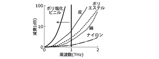
- FIG. 1 is a diagram showing the relationship between the attenuation factor and the frequency when an electromagnetic wave passes through a substance.
- FIG. 2 is a diagram showing the relationship between the wavelength of electromagnetic waves and the resolution.
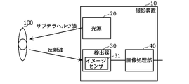
- FIG. 3 is a block diagram showing the configuration of the photographing apparatus according to the first embodiment.
- FIG. 4 is a schematic diagram showing the configuration of the light source according to the first embodiment.
- FIG. 5 is a schematic view showing a cross section of the detector according to the first embodiment receiving the reflected wave.
- FIG. 6 is a schematic view showing a cross section of a detector according to the first comparative example receiving a reflected wave.
- FIG. 7 is a schematic view showing how the photographing apparatus according to the first embodiment is installed.
- FIG. 1 is a diagram showing the relationship between the attenuation factor and the frequency when an electromagnetic wave passes through a substance.
- FIG. 2 is a diagram showing the relationship between the wavelength of electromagnetic waves and the resolution.
- FIG. 3 is a block diagram showing the configuration of the
- FIG. 8 is a block diagram showing the configuration of the photographing apparatus according to the second embodiment.
- FIG. 9 is a schematic view showing a cross section of the third detector according to the second embodiment receiving the reflected wave.
- FIG. 10 is a schematic view showing a cross section of the detector according to the second comparative example receiving the reflected wave.
- FIG. 11 is a schematic view showing a cross section of a state in which the photographing apparatus according to the second embodiment is installed.
- FIG. 12 is a flowchart of the image analysis process.
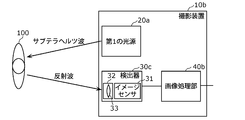
- FIG. 13 is a block diagram showing the configuration of the photographing apparatus according to the third embodiment.
- FIG. 14 is a schematic view showing how the photographing apparatus according to the third embodiment photographs an object to be measured.
- FIG. 15A is a schematic view showing how the reflecting surface of the reflector according to the comparative example reflects the sub-terahertz wave.
- FIG. 15B is a schematic view showing how the sub-terahertz wave reflected by the reflecting surface of the reflector according to the comparative example causes an interference draft.
- FIG. 15C is an enlarged cross-sectional view showing an example of the reflective surface of the reflector according to the third embodiment.
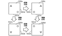
- FIG. 16A is a plan view of each of the plurality of unit regions according to the third embodiment.
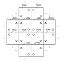
- FIG. 16B is a schematic view showing how a plurality of unit regions are arranged on the reflective surface of the reflector according to the third embodiment.
- FIG. 17 is a schematic view showing a cross section of an uneven inclined portion on the reflecting surface according to the third embodiment.
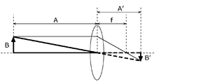
- FIG. 18A is a schematic view showing the relationship between the subject and the real image in the optical system according to the third embodiment.
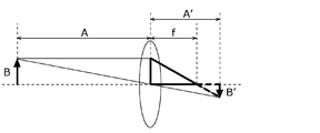
- FIG. 18B is a schematic diagram showing the relationship between the subject and the real image in the optical system according to the third embodiment.
- FIG. 18C is a schematic view showing how the points at the positions of the imaging sub-terahertz wave radiation region according to the third embodiment form an image on the image sensor.
- FIG. 18D is a schematic view showing how the points at the positions of the imaging sub-terahertz wave radiation region according to the third embodiment form an image on the image sensor.
- FIG. 19 is a schematic view showing a part of the appearance of the photographing apparatus according to the modified example.
- the inventor has diligently studied a photographing device capable of detecting a dangerous object (for example, a knife, etc.) hidden under clothes or the like in a bag or the like.
- a dangerous object for example, a knife, etc.
- the inventor examined the relationship between the attenuation factor and frequency when electromagnetic waves are transmitted through substances that are materials such as clothes and bags.
- FIG. 1 is a diagram showing the relationship between the attenuation rate and the frequency when an electromagnetic wave passes through a substance.
- electromagnetic waves having a frequency of 1 THz or less can transmit most of the substances used as materials such as clothes and bags.
- the inventor examined the frequency that realizes the resolution at which the shape of a dangerous object can be photographed.
- Equation 1 The relationship between the frequency (wavelength) of electromagnetic waves and the resolution (resolution) is expressed by (Equation 1) known as Abbe's equation.
- Equation 1 ⁇ is the resolution
- ⁇ is the wavelength of the electromagnetic wave
- NA is the numerical aperture of the lens
- n is the refractive index of the medium between the object and the lens
- ⁇ is the optical axis of the light beam incident on the lens from the object.
- Equation 2 is obtained.
- the shape of a dangerous object such as a knife can be photographed by using an electromagnetic wave having a frequency of 80 MHz (0.08 THz) or higher.
- the inventor through these studies, in order to take a picture capable of detecting a dangerous substance hidden in a bag under clothes or the like, the inventor is a sub-terahertz electromagnetic wave having a frequency of 0.08 THz or more and 1 THz or less. We found that it is appropriate to use waves.
- subterahertz waves do not adversely affect the human body. Therefore, there is no problem in using the sub-terahertz wave as an electromagnetic wave radiated toward the human body from the viewpoint of safety.
- sub-terahertz waves are specularly reflected on the human body, metals, etc.
- a point light source here, sub-terahertz waves
- the shape of the human body, the shape of metallic dangerous objects such as blades, etc. must be photographed with high accuracy. Is difficult.
- the inventor examined the shape of the light source that radiates the sub-terahertz wave.
- the light source that emits the sub-terahertz wave is a surface light source
- the inventor can irradiate the object to be imaged with the sub-terahertz wave from various angles as compared with the case of a point light source. Since it is possible, it has been found that the shape of an object that mirror-reflects a sub-terahertz wave such as a human body or metal can be imaged more accurately than before.
- the inventor came up with the following imaging device based on the above findings.
- the photographing apparatus includes a surface light source including a radiation surface that radiates a subterrahertz wave with respect to the measurement object, and a reflected wave of the subterrahertz wave radiated from the radiation surface by the measurement object.
- the surface light source includes a detector including an image sensor that receives the wave, and the surface light source diffuses and reflects one or more point light sources that emit subterahertz waves and the subterahertz waves that are emitted from the one or more point light sources. Therefore, it has a reflecting plate that generates a subterrahertz wave radiated from the radiating surface, and the reflecting surface of the reflecting plate is an uneven surface having an average length RSm of a roughness curve element of 0.3 mm or more.
- diffuse reflection means that a sub-terahertz wave incident on a reflecting surface at one incident angle from a macroscopic point of view has a structure of an uneven surface having a plurality of microscopic irregularities, so that light is reflected at a plurality of reflection angles. It means to be reflected.
- the above imaging device photographs using sub-terahertz waves radiated from a surface light source. Therefore, according to the above-mentioned photographing apparatus, it is possible to photograph the shape of an object such as a human body or metal hidden under clothes or the like with higher accuracy than before. Further, the average length RSm of the roughness curve element of the reflecting surface is equal to or larger than the wavelength of the sub-terahertz wave. Therefore, according to the above-mentioned photographing apparatus, even if the sub-terahertz wave radiated from each point light source is a coherent electromagnetic wave, the generation of interference fringes in the sub-terahertz wave radiated from the radiating surface is suppressed.
- the detector has an optical system that forms an image of the reflected wave on the image sensor, the incident pupil diameter of the optical system is ⁇ , and the distance between the radiation surface and the measurement object is b.
- the reflective surface has ( It has one or more unit regions composed of uneven surfaces containing two or more frequency components below ⁇ ⁇ b / c) / ⁇ , and the width of each of the one or more unit regions is ⁇ ⁇ b / c or more.
- the average length RSm of the roughness curve element may be less than 2 ⁇ ⁇ ⁇ b / c.
- the one or more unit areas are a plurality of units including the first unit area and the second unit area, and the first unit area and the second unit area share one side.
- the uneven shape in the first unit region and the uneven shape in the second unit region may have a line-symmetrical relationship with the one side as the target axis.
- the detector has an optical system that forms an image of the reflected wave on the image sensor, the width of the imaging range of the measurement object is a, and the distance between the measurement object and the optical system is c.
- the angle ⁇ 1 that is half the width of the intensity of the subterrahertz wave in the diffuse reflection by the reflector is It may be the above.
- the detector has an optical system that forms an image of the reflected wave on the image sensor, the width of the imaging range of the measurement object is a, and the distance between the measurement object and the optical system is c.
- the angle ⁇ 2 which is the half width of the inclination angle distribution in the unevenness of the reflection surface, is It may be the above.
- each of the embodiments shown here shows a specific example of the present disclosure. Therefore, the numerical values, shapes, components, arrangement and connection forms of the components, steps (processes), order of steps, etc. shown in the following embodiments are merely examples and do not limit the present disclosure. .. Further, each figure is a schematic view and is not necessarily exactly illustrated.
- the term plane means not only a plane that is exactly flat, but also a plane that is substantially flat.
- the term spheroidal surface means not only a surface that is exactly a spheroidal surface but also a surface that is substantially a spheroidal surface.
- the comprehensive or specific embodiment of the present disclosure may be realized by a recording medium such as a system, a method, an integrated circuit, a computer program or a computer-readable CD-ROM, and the system, the method, the integrated circuit, the computer. It may be realized by any combination of a program and a recording medium.
- FIG. 3 is a block diagram showing the configuration of the photographing apparatus 10 according to the first embodiment.
- the photographing apparatus 10 includes a light source 20, a detector 30, and an image processing unit 40.
- the light source 20 radiates a sub-terahertz wave to the object to be measured (here, the person 100).
- FIG. 4 is a schematic diagram showing the configuration of the light source 20.
- the light source 20 includes a point light source 21 and an optical element 23.
- the point light source 21 radiates a sub-terahertz wave radially in all directions around the point light source 21.
- the optical element 23 has a radiation surface 22 and generates a sub-terahertz wave radiated from the radiation surface 22 from the sub-terahertz wave radiated from the point light source 21.
- the radial surface 22 is a flat surface. Therefore, the optical element 23 functions as a surface light source that radiates a sub-terahertz wave from the plane radiation surface 22.
- the radiation surface of the sub-terahertz wave is a plane for convenience of explanation, but it may be an inner surface of a spheroid, an inner surface of a spherical surface, which will be described later, or an arbitrary curved surface.
- FIG. 5 is a schematic view showing a cross section of a light source 20 functioning as a surface light source that emits a sub-terahertz wave, and a detector 30 described later receiving a reflected wave from a measurement object.
- the optical element 23 is configured to include a diffuser plate 24, and the main plane on the front side thereof is a radiation surface 22.
- the diffuser plate 24 diffuses and transmits the sub-terahertz wave radiated from the point light source 21, thereby generating the sub-terahertz wave radiated from the radiation surface 22.
- the diffuser plate 24 has a flat plate shape parallel to the radiation surface 22 when viewed from a macro perspective. On the other hand, when viewed from a microscopic point of view, the diffuser plate 24 has minute undulations formed on the entire surface so that the transmitted sub-terahertz wave is diffused.
- the point light source 21 is arranged on the back side of the optical element 23.
- the sub-terahertz wave radiated from the point light source 21 penetrates into the inside of the optical element 23 from the main surface on the back side of the optical element 23 and reaches the diffuser plate 24.
- the sub-terahertz wave that has reached the diffuser plate 24 is diffused and transmitted through the diffuser plate 24.
- the sub-terahertz wave diffused and transmitted through the diffusion plate 24 propagates to the radiation surface 22 and is radiated to the outside from the radiation surface 22.
- the detector 30 includes an image sensor 31.
- the image sensor 31 converts the image of the sub-terahertz wave emitted from the subject into an electric signal according to its intensity. Then, the image sensor 31 generates an image based on the converted electric signal.
- imaging the fact that the image sensor 31 generates an image including an image of the subject is also referred to as “imaging”.
- the image sensor 31 Receives the reflected wave.
- the image sensor 31 receives the reflected wave from the region of the angle at which the mirror-reflected reflected wave is incident on the image sensor 31 among the body of the person 100 and the blade hidden by the person 100.
- the light source 20 functions as a surface light source that radiates a sub-terahertz wave from the radiation surface 22. Therefore, the light source 20 can irradiate the person 100 with sub-terahertz waves from various angles. Therefore, as shown in FIG. 5, the image sensor 31 reflects from a relatively wide range of the surface of the person 100, that is, the body of the person 100 and the surface of the blade hidden by the person 100. Can receive waves. Therefore, the photographing device 10 can image a relatively wide area 101 of the body of the person 100 and the surface of the blade hidden by the person 100.
- FIG. 6 shows a first image pickup device according to a first comparative example in which the optical element 23 is removed from the light source 20, that is, the first configuration in which the sub-terahertz wave radiated by the point light source 21 is radiated to the outside as it is. It is a schematic diagram which shows the cross section of the state which the detector 30 receives a reflected wave in the photographing apparatus which concerns on a comparative example.
- the photographing apparatus according to the first comparative example in the image sensor 31, the reflected wave reflected from the mirror surface of the body of the person 100 and the surface of the blade hidden by the person 100 is the image sensor 31. Only the reflected wave from the region 101a at an angle incident on the can be received. Therefore, the photographing apparatus according to the first comparative example can image only a relatively narrow range 101a of the body of the person 100 and the surface of the blade hidden by the person 100.
- the photographing device 10 according to the first embodiment can image the body of the person 100 and the shape of the blade hidden by the person 100 with higher accuracy than the photographing device according to the first comparative example.
- the detector 30 outputs the image generated by the image sensor 31 to the image processing unit 40.
- the image processing unit 40 When the image processing unit 40 receives an image from the detector 30, the image processing unit 40 outputs the received image to the outside, performs image processing on the received image, and outputs the result of the image processing to the outside.
- the image processing performed by the image processing unit 40 determines, for example, whether or not the image output from the detector 30 includes an object having a predetermined feature (for example, an object having the feature of a blade), and determines. When it is determined that an object having the characteristics of the above is included, the process may be a process of outputting a predetermined detection signal (for example, an alarm indicating that the object having the characteristics of the blade is being photographed).
- the image processing unit 40 includes, for example, a processor and a memory, and the processor may be realized by executing a program stored in the memory.
- the photographing device 10 having the above configuration is installed, for example, in a passage in an airport, near a ticket gate of a station, or the like.
- FIG. 7 is a schematic view showing how the photographing device 10 is installed in the passage in the airport.
- the photographing device 10 may be installed, for example, in which the optical element 23 and the detector 30 are embedded inside the wall of the crank-shaped passage 200 at the airport.
- the sub-terahertz wave radiated from the radiating surface 22 inside the wall passes through the wall and irradiates the person 100. Then, the reflected wave of the sub-terahertz wave reflected by the person 100 passes through the wall again and is incident on the detector 30. As a result, the photographing device 10 can photograph a dangerous object such as a knife hidden under clothes or the like by a person 100 passing through the passage 200.
- FIG. 8 is a block diagram showing the configuration of the photographing apparatus 10a according to the second embodiment.
- the light source 20 is changed to the first light source 20a and the second light source 20b from the photographing device 10 according to the first embodiment, and the detector 30 is the first detection.
- the device 30a and the second detector 30b are changed, and the image processing unit 40 is changed to the image processing unit 40a.
- the first light source 20a radiates a sub-terahertz wave to the object to be measured (here, the person 100).
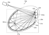
- FIG. 9 is a schematic view showing a cross section showing the configuration of the first light source 20a, how the first light source 20a functions as a surface light source, and how the first detector 30a, which will be described later, receives the reflected wave. ..
- the first light source 20a includes a point light source 21a and an optical element 23a.
- the point light source 21a radiates a sub-terahertz wave radially in all directions around the point light source 21a.
- the optical element 23a has a first radiation surface 22a, and generates a sub-terahertz wave radiated from the first radiation surface 22a from the sub-terahertz wave radiated from the point light source 21a.
- the first radial surface 22a is the inner surface of the spheroidal surface. Therefore, the optical element 23a functions as a surface light source that radiates a sub-terahertz wave from the first radiation surface 22a, which is the inner surface of the spheroidal surface.
- the optical element 23a is configured to include a reflector 24a, and the curved surface inside the optical element 23a is a first radiation surface 22a.
- the reflector 24a diffusely reflects the sub-terahertz wave radiated from the point light source 21a to generate the sub-terahertz wave radiated from the first radiation surface 22a. From a macroscopic point of view, the reflector 24a has a similar shape to the first radiation surface 22a, which is equal to or larger than the first radiation surface 22a, and the positions of the two focal points are the first radiation, respectively. It coincides with the positions of the two focal points on the surface 22a. On the other hand, when viewed from a microscopic point of view, the reflector 24a has minute undulations formed on the entire surface of the reflecting surface so that the reflected sub-terahertz wave is diffused.
- the point light source 21a is arranged at the focal point 301a of one of the two focal points of the first radiation surface 22a.
- the sub-terahertz wave radiated from the point light source 21a penetrates into the inside of the optical element 23a from the first radiation surface 22a and reaches the reflector 24a.
- the sub-terahertz wave that has reached the reflector 24a is diffusely reflected by the reflector 24a.
- the sub-terahertz wave diffusely reflected by the reflector 24a propagates to the first radiation surface 22a and is radiated to the outside from the first radiation surface 22a.
- the externally radiated sub-terahertz wave irradiates, for example, a person 100 in the vicinity of the other focal point 302a of the two focal points of the first radiation surface 22a.
- the first radiation surface 22a and the reflector 24a have different configurations, it is not necessarily limited to the example in which the first radiation surface 22a and the reflector 24a have different configurations.
- the first radiation surface 22a may be the reflection surface of the reflector 24a.
- the second light source 20b in FIG. 8 has the same function as the first light source 20a, and its shape has a mirror image relationship with the first light source 20a. Therefore, the second light source 20b is replaced with the point light source 21b from the description of the first light source 20a, except that the shape of the second light source 20b has a mirror image relationship with the first light source 20a, and the optical element 23a Is replaced with an optical element 23b, a reflecting plate 24a is replaced with a reflecting plate 24b, one focal 301a is replaced with one focal 301b, and the other focal 302a is replaced with the other focal 302b.
- the first detector 30a includes the first image sensor 31a.
- the first detector 30a is the same as the detector 30 according to the first embodiment. That is, the first image sensor 31a is the same as the image sensor 31 according to the first embodiment.
- the second detector 30b is the same as the first detector 30a. Therefore, the second detector 30b will be described by replacing the first image sensor 31a with the second image sensor 31b from the description of the first detector 30a.
- the first light source 20a functions as a surface light source that radiates a sub-terahertz wave from the first radiation surface 22a. Therefore, the first light source 20a can irradiate the person 100 near the other focal point 302a with the sub-terahertz wave from various angles. Therefore, as shown in FIG. 9, the first image sensor 31a covers a relatively wide range of the surface of the person 100, that is, the body of the person 100 and the surface of the blade hidden by the person 100. Can receive the reflected wave of. Therefore, the photographing device 10a can image a relatively wide area 102 of the body of the person 100 and the surface of the blade hidden by the person 100.
- FIG. 10 shows that the first detector 30a receives the reflected wave in the photographing apparatus according to the second comparative example in which the reflector 24a is changed from the first light source 20a to the reflector 24aa.
- the reflector 24aa has the same shape as the reflector 24a when viewed from a macroscopic viewpoint, while the reflecting surface is mirror-reflected so that the reflected subterahertz wave is mirror-reflected when viewed from a microscopic viewpoint.
- the entire surface is formed smoothly. Therefore, all the sub-terahertz waves radiated from one focal point 301a and reflected by the reflector 24aa travel toward the other focal point 302a regardless of where the reflecting plate 24aa is reflected.
- the first image sensor 31a is the body of the person 100 near the other focal point 302a and the surface of the blade hidden by the person 100.
- the photographing apparatus according to the second comparative example can image only a relatively narrow range 102a of the body of the person 100 and the surface of the blade hidden by the person 100.
- the photographing device 10a according to the second embodiment can image the body of the person 100 and the shape of the blade hidden by the person 100 with higher accuracy than the photographing device according to the second comparative example.
- the first detector 30a and the second detector 30b transmit the first image and the second image generated by the first image sensor 31a and the second image sensor 31b to the image processing unit 40a, respectively. Output.
- the image processing unit 40a When the image processing unit 40a receives the first image and the second image from the first detector 30a and the second detector 30b, respectively, the image processing unit 40a sends the received first image and the second image to the outside. At the same time as outputting, image processing is performed on the received first image and second image, and the result of the image processing is output to the outside.
- the image processing performed by the image processing unit 40a is, for example, an object having predetermined characteristics in the first image and the second image output from the first detector 30a and the second detector 30b (for example, a blade).
- an object having the above-mentioned characteristics is included, and when it is determined that at least one of the first image and the second image contains an object having a predetermined characteristic.
- It may be a process of outputting a predetermined detection signal (for example, an alarm indicating that an object having the characteristics of a blade is being photographed).
- the image processing performed by the image processing unit 40a further determines that at least one of the first image and the second image contains an object having a predetermined feature, the first image.
- the image processing unit 40a may be realized, for example, by including a processor and a memory, and the processor executing a program stored in the memory.
- the photographing device 10a having the above configuration is installed, for example, in the passage in the airport or near the ticket gate of the station.
- FIG. 11 is a schematic view showing a cross section of the photographing device 10a installed in the passage near the ticket gate of the station.
- the photographing device 10a may be installed, for example, in which the optical element 23a and the optical element 23b are embedded inside the wall of the passage 400 near the ticket gate of the station. More specifically, the photographing apparatus 10a is installed, for example, by embedding the optical element 23a inside the wall 401a which is one side wall of the passage 400, and the optical element 23b is installed in the wall 401b which is the other side wall of the passage 400. It may be embedded and installed inside the. At this time, the optical element 23a and the optical element 23b may be installed so that the other focal point 302a of the optical element 23a and the other focal point 302b of the optical element 23b substantially coincide with each other on the center line of the passage 400. desirable.
- the sub-terahertz wave radiated from the point light source 21a and the sub-terahertz wave radiated from the point light source 21b are placed in a region near the other focal point 302a and the other focal point 302b (hereinafter,). , Also referred to as the "focus area") can be irradiated from various angles. Therefore, as shown in FIG. 11, the first image sensor 31a and the second image sensor 31b included in the first detector 30a and the second detector 30b are the person 100 walking in the focal region.
- the reflected wave can be received from a relatively wide range of the surface of the person 100, that is, the body of the person 100 and the surface of the blade hidden by the person 100.
- the photographing device 10a can image a relatively wide area 103 of the body of the person 100 and the surface of the blade hidden by the person 100. Further, the first image sensor 31a and the second image sensor 31b included in the first detector 30a and the second detector 30b each receive reflected waves from the region 103 at different angles. do. Therefore, the photographing device 10a can image the body of the person 100 and the blade hidden by the person 100, which are the same subjects, from different angles.
- the photographing device 10a performs image analysis processing as an example.
- the photographing device 10a captures the first image and the second image, and based on the captured first image and the second image, an object having the characteristics of a blade is photographed. This is a process of outputting a detection signal, which is an alarm indicating that the image is running.
- FIG. 12 is a flowchart of the image analysis process performed by the photographing apparatus 10a.
- the image analysis process is started when a person invades the focal area.
- the photographing device 10a detects that the person has invaded the focal area.
- the photographing device 10a detects that a person has invaded the focal area by receiving, for example, a signal indicating that the person has invaded the focal area from an external sensor that detects that the person has invaded the focal area. You may.
- the first light source 20a and the second light source 20b radiate a sub-terahertz wave at the same timing in synchronization with each other (step S100). Further, the first detector 30a and the second detector 30b entered the focal region at the timing when the first light source 20a and the second light source 20b emit the sub-terahertz wave in synchronization with each other. An image of a person is taken (step S110). Then, the first detector 30a and the second detector 30b output the first image and the second image to the image processing unit 40a, respectively.
- the image processing unit 40a receives the output first image and the second image, and receives the first image and the second image. Is output to the outside (step S120). Then, the image processing unit 40a determines whether or not at least one of the first image and the second image includes an object having the characteristic of the blade, which is a predetermined characteristic (step S130).
- step S130 when it is not determined that at least one of the first image and the second image contains an object having a predetermined feature (step S130: No), the image processing unit 40a , The first image and the second image are comparatively brightly combined to generate a composite image, and the generated composite image is output to the outside (step S140). Then, the image processing unit 40a determines whether or not the generated composite image includes an object having the characteristic of the blade, which is a predetermined characteristic (step S150).
- step S130 when it is determined that at least one of the first image and the second image contains an object having a predetermined feature (step S130: Yes), and in the process of step S150.
- step S150: Yes the image processing unit 40a gives an alarm indicating that the object having the feature of the blade is being photographed.
- a certain detection signal is output to the outside (step S160).
- step S160 When the process of step S160 is completed and when it is not determined in the process of step S150 that the composite image contains an object having a predetermined feature (step S150: No), the photographing device 10a captures the image. End the analysis process.
- FIG. 13 is a block diagram showing the configuration of the photographing apparatus 10b according to the third embodiment.
- the second light source 20b and the second detector 30b are deleted from the photographing device 10a according to the second embodiment, and the first detector 30a is the detector. It is changed to 30c, and the image processing unit 40a is changed to the image processing unit 40b.
- the detector 30c includes an image sensor 31 and an optical system 32.
- the optical system 32 forms an image of the reflected wave of the sub-terahertz wave radiated from the first radiation surface 22a by the object to be measured (here, the person 100) on the image sensor 31.
- the optical system 32 includes at least one lens including a lens 33.
- the entrance pupil diameter of the optical system 32 is ⁇ .
- the detector 30c outputs the image generated by the image sensor 31 to the image processing unit 40b.
- the image processing unit 40b When the image processing unit 40b receives an image from the detector 30c, it outputs the received image to the outside, performs image processing on the received image, and outputs the result of the image processing to the outside.
- the image processing performed by the image processing unit 40b is the same processing as the image processing performed by the image processing unit 40 according to the first embodiment.
- the reflector 24a constituting the first light source 20a has a reflecting surface so as to diffusely reflect the sub-terahertz wave radiated from the point light source 21a when viewed from a microscopic viewpoint. Small undulations are formed on the entire surface.
- the structure of the reflective surface of the reflector 24a will be described more specifically.
- the reflecting surface of the reflector 24a is an uneven surface having an average length RSm of the roughness curve element of 0.3 mm or more.
- the wavelength of the sub-terahertz wave radiated from the point light source 21a is 0.3 mm or less. Therefore, the sub-terahertz wave radiated from the point light source 21a is diffusely reflected when it is applied to the reflecting surface which is an uneven surface having an average length RSm of the roughness curve element of 0.3 mm or more.
- the reflecting surface of the reflecting plate 24a is an uneven surface in which the average length RSm of the roughness curve element is equal to or higher than the wavelength of the sub-terahertz wave, so that the sub-terahertz wave radiated from the point light source 21a Achieves diffuse reflection.
- FIG. 14 is a schematic view showing how the photographing device 10b photographs an object to be measured.
- the photographing range 110 is an area of the surface of the object to be measured to be photographed by the photographing device 10b. As described in the second embodiment, the photographing range 110 is a region in the vicinity of the other focal point 302a (see FIG. 9 and the like) of the two focal points of the first radiation surface 22a. On the other hand, the point light source 21a is located at one of the two focal points of the first radiation surface 22a, the focal point 301a (see FIG. 9 and the like).
- the imaging sub-terahertz wave radiation region 120 is a part of the first radiation surface 22a, and is a source of the reflected light component imaged on the image sensor 31 among the reflected light by the measurement object. It is a region that radiates a sub-terahertz wave.
- the distance b is the distance between the first radiation surface 22a and the object to be measured. More specifically, the distance b is the distance between the imaging sub-terahertz wave radiation region 120 and the imaging range 110.
- the distance c is the distance between the object to be measured and the optical system 32. More specifically, the distance c is the distance between the photographing range 110 and the optical system 32.
- the width ⁇ 'of the imaged sub-terahertz wave radiation region 120 is determined by the following (Equation 3) depending on the positional relationship between the first radiation surface 22a, the object to be measured, and the optical system 32.
- FIG. 15A is a schematic view showing how the reflecting surface of the reflector according to the comparative example reflects the sub-terahertz wave.
- the radial surface according to the comparative example has a periodic structure having a pitch d.
- FIG. 15B is a schematic view showing how the sub-terahertz wave reflected by the reflecting surface of the reflector according to the comparative example causes an interference draft.
- the reflecting surface of the reflecting plate 24a in the imaging sub-terahertz wave radiation region 120 has a periodic structure consisting of only one frequency component of ⁇ '/ d in the spatial frequency region, the point light source 21a If the emitted sub-terahertz wave is a coherent sub-terahertz wave, the image formed on the image sensor 31 is relatively strongly affected by the interference draft.
- the reflective surface of the actual reflecting plate 24a has irregularities containing two or more frequency components below ⁇ '/ ⁇ in the spatial frequency region, where ⁇ is the wavelength of the sub-terahertz wave radiated from the point light source 21a. It is a face.
- the sub-terahertz wave radiated from the point light source 21a is a coherent sub-terahertz wave, the influence of the interference draft on the image of the measurement object formed on the image sensor 31 is reduced.
- FIG. 15C is an enlarged cross-sectional view showing an example of the reflective surface of the actual reflector 24a.
- the reflective surface of the reflector 24a is an uneven surface having spatial frequencies of 1 to 5 having the same intensity in the spatial frequency region.
- the reflecting surface of the reflector 24a is an uneven surface having a random shape.
- the reflective surface of the reflector 24a has a plurality of unit regions having a width of ⁇ ⁇ b / c or more.
- each unit region will be described as a region in which the shape seen from the direction perpendicular to the tangent plane of the spheroidal plane in the macro viewpoint of the reflecting surface is substantially rectangular.
- the width of the unit area means the shorter distance among the distances between the opposite sides of the substantially rectangular shape.
- FIG. 16A shows the direction perpendicular to the tangent plane of the spheroidal plane in the macroscopic viewpoint of the reflecting surface for each of the plurality of unit regions 500 (that is, the unit region 500a to the unit region 500d) of the reflecting surface of the reflecting plate 24a. It is a plan view seen from.
- the position of each tangent plane in contact with the spheroidal plane is the position of the center of the rectangle shown as the unit region 500a to the unit region 500d in FIG. 16A.
- each unit region 500 is composed of an uneven surface containing two or more frequency components below ⁇ '/ ⁇ in the spatial frequency region, where ⁇ is the wavelength of the sub-terahertz wave radiated from the point light source 21a.
- FIG. 16B is a schematic view showing how a plurality of unit regions 500 are arranged on the reflective surface of the reflector 24a.
- the unit region 500a and the unit region 500b share the side 501a in the unit region 500a and the side 501b in the unit region 500b as one side. They are placed in contact with each other on one side that they share.
- the uneven shape in the unit region 500a and the uneven shape in the unit region 500b have a line-symmetrical relationship with one side as the target axis.
- the unit region 500a and the unit region 500c share the side 502a in the unit region 500a and the side 502c in the unit region 500c as one side, and are in contact with each other on the shared one side. Be placed.
- the uneven shape in the unit region 500a and the uneven shape in the unit region 500c have a line-symmetrical relationship with one side as the target axis.
- the unit region 500b and the unit region 500d share the side 502b in the unit region 500b and the side 502d in the unit region 500d as one side, and are in contact with each other on the shared one side. Be placed.
- the uneven shape in the unit region 500b and the uneven shape in the unit region 500d have a line-symmetrical relationship with one side as the target axis.
- the unit region 500c and the unit region 500d share the side 501c in the unit region 500c and the side 501d in the unit region 500d as one side, and are in contact with each other on the shared one side. Be placed.
- the uneven shape in the unit region 500c and the uneven shape in the unit region 500d have a line-symmetrical relationship with one side as the target axis.
- the unit regions 500a to the unit region 500d are arranged without gaps on the entire reflecting surface of the reflector 24a.
- the reflecting surface of the reflecting plate 24a has a width of ⁇ '/ ⁇ in the spatial frequency region, where ⁇ is the wavelength of the sub-terahertz wave radiated from the point light source 21a in an arbitrary region having a width of ⁇ '.
- ⁇ is the wavelength of the sub-terahertz wave radiated from the point light source 21a in an arbitrary region having a width of ⁇ '.
- the angle ⁇ 1 indicates an angle that is half-width and half width of the intensity of the sub-terahertz wave in the diffuse reflection at an arbitrary position of the reflector 24a.
- the photographing range 110 is located within the range within the angle ⁇ 1. That is, the angle ⁇ 1 satisfies the following (Equation 5).
- the variation in the intensity of the sub-terahertz wave irradiated by the reflector 24a within the photographing range 110 is suppressed to 1/2 or less.
- FIG. 17 is a schematic view showing a cross section of an uneven inclined portion on the reflecting surface of the reflecting plate 24a.
- the variation in the intensity of the sub-terahertz wave irradiated by the reflector 24a within the photographing range 110 is suppressed to 1/2 or less.
- the upper limit of the average length RSm of the roughness curve element of the reflecting surface of the reflector 24a will be considered.
- 18A and 18B are schematic views showing the relationship between the subject and the real image in the optical system 32.
- the focal length f is the focal length of the optical system 32
- the distance A is the distance from the optical system 32 to the subject
- the height B is the height of the subject
- the distance A. ′ Is the distance from the optical system 32 to the real image of the subject imaged by the optical system 32
- the height B ′ is the height of the real image.
- 18C and 18D are schematic views showing how the points at the positions of the imaging sub-terahertz wave radiation region 120 form an image on the image sensor 31 by the optical system 32.
- the distance c is the distance between the imaging range 110 and the optical system 32
- the distance e is the distance between the imaging subterahertz wave radiation region 120 and the optical system 32, that is, the imaging subterahertz.
- the distance b which is the sum of the distance b and the distance c between the wave radiation region 120 and the imaging range 110
- the distance c' is the distance between the optical system 32 and the image sensor 31, and the distance e'is the imaging sub.
- the point at the position of the terahertz wave radiation region 120 is the distance between the position where the image is formed and the optical system 32
- the width ⁇ ′′ is the point at the position of the imaging sub-terahertz wave radiation region 120 formed on the image sensor 31.
- the width of the image that is, the width indicating the spread of the out-of-focus image of the point formed at the image sensor 31 at the position of the imaged sub-terahertz wave radiation region 120.
- the length P is the average length RSm of the roughness curve element of the reflecting surface of the reflecting plate 24a
- the height P ′′ is the height P of the position of the first radiation surface 22a.
- the height of the subject that is, the height of the real image of the subject, which is the average length RSm of the roughness curve elements of the reflecting surface of the reflecting plate 24a.
- the average length RSm of the roughness curve element of the reflecting surface of the reflecting plate 24a is 2 ⁇ ⁇ ⁇ b /. It turns out that it is desirable that it is less than c.
- the photographing apparatus 10a includes a first light source 20a including an optical element 23a having a first radiating surface 22a which is an inner surface of a spheroid surface, and a second light source 20a which is an inner surface of the spheroidal surface. It has been described that the configuration includes a second light source 20b including an optical element 23b having a radiation surface 22b of the above.
- the photographing apparatus according to the modified example which is another example of one aspect of the present disclosure is the inner surface of the spheroidal surface instead of the optical element 23a from the photographing apparatus 10a according to the second embodiment.
- the first light source according to the modified example in which the shape of the radiating surface 22a of 1 is changed to the inner surface of a spherical surface is provided, and instead of the optical element 23b, the shape of the second radiating surface 22b which is the inner surface of the spheroidal surface is a spherical surface. It may be modified and configured to include a second light source according to the modified example on the inner surface of the.
- FIG. 19 is a schematic view showing a part of the appearance of the photographing apparatus according to the modified example.
- the first light source 20c according to the modified example includes a point light source 21a and an optical element 23c having a first radiation surface 22c which is an inner surface of a spherical surface. Consists of.
- the point light source 21a is arranged near the center of the spherical surface.
- the second light source 20d according to the modified example includes a point light source 21b and an optical element 23d having a second radiation surface 22d which is an inner surface of a spherical surface.
- the point light source 21b is arranged near the center of the spherical surface.
- the optical element 23 has been described as being configured to include the diffuser plate 24.
- the optical element 23 may be the diffuser plate 24 itself. In this case, the surface of the diffusion plate 24 becomes the radiation surface 22.
- the optical element 23a and the optical element 23b have been described as including the reflector 24a and the reflector 24b, respectively.
- the optical element 23a and the optical element 23b may be the reflector 24a itself and the reflector 24b itself, respectively.
- the reflective surface of the reflector 24a and the reflective surface of the reflector 24b become the first radiation surface 22a and the second radiation surface 22b, respectively.
- the light source 20 includes one point light source 21.
- the number of point light sources included in the light source 20 is not necessarily limited to one, and may be plural.
- the optical element 23 generates a sub-terahertz wave radiated from the radiation surface 22 from the sub-terahertz wave radiated from these a plurality of point light sources.
- the first light source 20a and the second light source 20b include one point light source 21a and one point light source 21b, respectively.
- the number of point light sources included in the first light source 20a and the second light source 20b is not necessarily limited to one, and may be plural.
- the optical element 23a and the optical element 23b generate a sub-terahertz wave radiated from the first radiation surface 22a and the second radiation surface 22b from the sub-terahertz waves radiated from the plurality of point light sources, respectively. It will be.
- the first radiating surface 22a and the second radiating surface 22b have been described as being inner surfaces of a spheroidal surface.
- the first radiating surface 22a and the second radiating surface 22b are not necessarily limited to examples of being the inner surface of an accurate spheroid, and for example, a polyhedron composed of a large number of minute polygons approximated to the spheroid. It may be.
- each of at least one unit region 500 is a region in which the shape seen from the direction perpendicular to the tangent plane of the spheroidal plane in the macroscopic viewpoint of the reflecting surface of the reflecting plate 24a is substantially rectangular. It was explained as. However, each of the at least one unit region 500 does not necessarily have to be substantially rectangular as long as the shape can cover the entire reflective surface of the reflector 24a without a gap by the at least one unit region 500.
- each of the at least one unit region 500 may be a region in which the shape seen from the direction perpendicular to the tangent plane of the spheroidal plane in the macro viewpoint of the reflecting surface of the reflector 24a is a substantially regular hexagon. In this case, the width of the unit area is the distance between the opposite sides of the substantially regular hexagon.
- One aspect of the present disclosure may be not only the photographing apparatus according to the first to third embodiments, but also an imaging method in which a characteristic component included in the photographing apparatus is a step.
- One aspect of the present disclosure may be a program that causes a computer to perform each characteristic step included in the photographing method.
- one aspect of the present disclosure may be a computer-readable non-temporary recording medium on which such a program is recorded.
- This disclosure can be widely used in a photographing device for photographing an object.
Landscapes
- Physics & Mathematics (AREA)
- Spectroscopy & Molecular Physics (AREA)
- General Physics & Mathematics (AREA)
- Engineering & Computer Science (AREA)
- Electromagnetism (AREA)
- Remote Sensing (AREA)
- Radar, Positioning & Navigation (AREA)
- Computer Networks & Wireless Communication (AREA)
- Health & Medical Sciences (AREA)
- Biochemistry (AREA)
- Immunology (AREA)
- Pathology (AREA)
- Toxicology (AREA)
- General Health & Medical Sciences (AREA)
- Life Sciences & Earth Sciences (AREA)
- Analytical Chemistry (AREA)
- Chemical & Material Sciences (AREA)
- Optics & Photonics (AREA)
- Investigating Or Analysing Materials By Optical Means (AREA)
Priority Applications (4)
| Application Number | Priority Date | Filing Date | Title |
|---|---|---|---|
| JP2022508065A JP7645452B2 (ja) | 2020-03-18 | 2020-12-17 | 撮影装置 |
| EP20925147.9A EP4123271A4 (en) | 2020-03-18 | 2020-12-17 | PHOTOGRAPHIC DEVICE |
| CN202080098553.9A CN115280098A (zh) | 2020-03-18 | 2020-12-17 | 摄影装置 |
| US17/940,372 US12259320B2 (en) | 2020-03-18 | 2022-09-08 | Imaging device |
Applications Claiming Priority (2)
| Application Number | Priority Date | Filing Date | Title |
|---|---|---|---|
| JP2020048096 | 2020-03-18 | ||
| JP2020-048096 | 2020-03-18 |
Related Child Applications (1)
| Application Number | Title | Priority Date | Filing Date |
|---|---|---|---|
| US17/940,372 Continuation US12259320B2 (en) | 2020-03-18 | 2022-09-08 | Imaging device |
Publications (1)
| Publication Number | Publication Date |
|---|---|
| WO2021186822A1 true WO2021186822A1 (ja) | 2021-09-23 |
Family
ID=77771913
Family Applications (1)
| Application Number | Title | Priority Date | Filing Date |
|---|---|---|---|
| PCT/JP2020/047117 Ceased WO2021186822A1 (ja) | 2020-03-18 | 2020-12-17 | 撮影装置 |
Country Status (5)
| Country | Link |
|---|---|
| US (1) | US12259320B2 (https=) |
| EP (1) | EP4123271A4 (https=) |
| JP (1) | JP7645452B2 (https=) |
| CN (1) | CN115280098A (https=) |
| WO (1) | WO2021186822A1 (https=) |
Families Citing this family (1)
| Publication number | Priority date | Publication date | Assignee | Title |
|---|---|---|---|---|
| EP4123271A4 (en) * | 2020-03-18 | 2023-07-26 | Panasonic Intellectual Property Management Co., Ltd. | PHOTOGRAPHIC DEVICE |
Citations (4)
| Publication number | Priority date | Publication date | Assignee | Title |
|---|---|---|---|---|
| US5517575A (en) * | 1991-10-04 | 1996-05-14 | Ladewski; Theodore B. | Methods of correcting optically generated errors in an electro-optical gauging system |
| JP2001509269A (ja) * | 1997-01-17 | 2001-07-10 | イギリス国 | ミリメートル波撮像装置 |
| US8835849B1 (en) | 2010-02-10 | 2014-09-16 | Mvt Equity Llc | Method and apparatus for detection of concealed objects in passive thermal images using environment control |
| JP2016144164A (ja) * | 2015-02-05 | 2016-08-08 | 国立研究開発法人情報通信研究機構 | 電波反射体 |
Family Cites Families (25)
| Publication number | Priority date | Publication date | Assignee | Title |
|---|---|---|---|---|
| FI107407B (fi) * | 1997-09-16 | 2001-07-31 | Metorex Internat Oy | Alimillimetriaalloilla toimiva kuvausjärjestelmä |
| US6777684B1 (en) * | 1999-08-23 | 2004-08-17 | Rose Research L.L.C. | Systems and methods for millimeter and sub-millimeter wave imaging |
| JP2002258272A (ja) * | 2001-02-28 | 2002-09-11 | Nec Corp | 反射板並びに反射型液晶表示装置 |
| US20090240139A1 (en) * | 2008-03-18 | 2009-09-24 | Steven Yi | Diffuse Optical Tomography System and Method of Use |
| JP5291983B2 (ja) * | 2008-05-12 | 2013-09-18 | 浜松ホトニクス株式会社 | テラヘルツ波周波数分解イメージング装置 |
| US9086483B2 (en) * | 2011-03-28 | 2015-07-21 | Northrop Grumman Guidance And Electronics Company, Inc. | Systems and methods for detecting and/or identifying materials |
| US9207317B2 (en) * | 2011-04-15 | 2015-12-08 | Ariel-University Research And Development Company Ltd. | Passive millimeter-wave detector |
| US9268017B2 (en) * | 2011-07-29 | 2016-02-23 | International Business Machines Corporation | Near-field millimeter wave imaging |
| DE102012003201A1 (de) * | 2012-02-17 | 2013-08-22 | Hübner GmbH | Verfahren und Vorrichtung zur Untersuchung von Postsendungen im Hinblick auf gefährliche Inhaltsstoffe |
| JP2014029478A (ja) * | 2012-07-03 | 2014-02-13 | Canon Inc | テラヘルツ波発生素子、テラヘルツ波検出素子、及びテラヘルツ時間領域分光装置 |
| JP6290036B2 (ja) * | 2013-09-25 | 2018-03-07 | 株式会社東芝 | 検査装置及び検査システム |
| WO2015050941A1 (en) * | 2013-10-04 | 2015-04-09 | Battelle Memorial Institute | Contrast phantom for passive millimeter wave imaging systems |
| MX361644B (es) * | 2013-12-24 | 2018-12-13 | Halliburton Energy Services Inc | Monitorización en tiempo real de la fabricación de elementos computacionales integrados. |
| WO2015101921A1 (en) * | 2013-12-30 | 2015-07-09 | University Of Manitoba | Imaging using gated elements |
| JP2017009296A (ja) * | 2015-06-16 | 2017-01-12 | キヤノン株式会社 | 電磁波伝搬装置及び情報取得装置 |
| JP6778856B2 (ja) * | 2016-03-25 | 2020-11-04 | パナソニックIpマネジメント株式会社 | ミラーパネル、ミラーフィルム及び表示システム |
| US11385105B2 (en) * | 2016-04-04 | 2022-07-12 | Teledyne Flir, Llc | Techniques for determining emitted radiation intensity |
| JP6843600B2 (ja) * | 2016-11-28 | 2021-03-17 | キヤノン株式会社 | 画像取得装置、これを用いた画像取得方法及び照射装置 |
| JP6916435B2 (ja) * | 2017-01-17 | 2021-08-11 | 澁谷工業株式会社 | テラヘルツ光発生装置 |
| US10585185B2 (en) * | 2017-02-03 | 2020-03-10 | Rohde & Schwarz Gmbh & Co. Kg | Security scanning system with walk-through-gate |
| EP3613150A4 (en) * | 2017-04-20 | 2020-12-02 | The Board of Trustees of the Leland Stanford Junior University | EXPANDABLE MILLIMETRIC WAVE NETWORKS WITH LARGE OPENINGS ACHIEVED BY MILLIMETRIC WAVE DIELECTRIC WAVE GUIDES |
| CN108444913A (zh) * | 2018-01-30 | 2018-08-24 | 中国科学院上海技术物理研究所 | 基于单元胞立体相位光栅和互参考技术的THz光谱仪 |
| CA3090636A1 (en) * | 2019-08-23 | 2021-02-23 | Institut National D'optique | Terahertz illumination source for terahertz imaging |
| WO2021070428A1 (ja) | 2019-10-09 | 2021-04-15 | パナソニックIpマネジメント株式会社 | 撮影装置 |
| EP4123271A4 (en) * | 2020-03-18 | 2023-07-26 | Panasonic Intellectual Property Management Co., Ltd. | PHOTOGRAPHIC DEVICE |
-
2020
- 2020-12-17 EP EP20925147.9A patent/EP4123271A4/en not_active Withdrawn
- 2020-12-17 JP JP2022508065A patent/JP7645452B2/ja active Active
- 2020-12-17 CN CN202080098553.9A patent/CN115280098A/zh active Pending
- 2020-12-17 WO PCT/JP2020/047117 patent/WO2021186822A1/ja not_active Ceased
-
2022
- 2022-09-08 US US17/940,372 patent/US12259320B2/en active Active
Patent Citations (4)
| Publication number | Priority date | Publication date | Assignee | Title |
|---|---|---|---|---|
| US5517575A (en) * | 1991-10-04 | 1996-05-14 | Ladewski; Theodore B. | Methods of correcting optically generated errors in an electro-optical gauging system |
| JP2001509269A (ja) * | 1997-01-17 | 2001-07-10 | イギリス国 | ミリメートル波撮像装置 |
| US8835849B1 (en) | 2010-02-10 | 2014-09-16 | Mvt Equity Llc | Method and apparatus for detection of concealed objects in passive thermal images using environment control |
| JP2016144164A (ja) * | 2015-02-05 | 2016-08-08 | 国立研究開発法人情報通信研究機構 | 電波反射体 |
Non-Patent Citations (1)
| Title |
|---|
| See also references of EP4123271A4 |
Also Published As
| Publication number | Publication date |
|---|---|
| JP7645452B2 (ja) | 2025-03-14 |
| EP4123271A1 (en) | 2023-01-25 |
| US20230003643A1 (en) | 2023-01-05 |
| US12259320B2 (en) | 2025-03-25 |
| CN115280098A (zh) | 2022-11-01 |
| JPWO2021186822A1 (https=) | 2021-09-23 |
| EP4123271A4 (en) | 2023-07-26 |
Similar Documents
| Publication | Publication Date | Title |
|---|---|---|
| JP7561340B2 (ja) | 撮影装置 | |
| JP5388543B2 (ja) | 外観検査装置 | |
| US20150133765A1 (en) | Biological information acquisition apparatus | |
| US20070114418A1 (en) | Security portal with THz trans-receiver | |
| JP2000501182A (ja) | 表面を特徴づけるための方法及び装置 | |
| JP7603239B2 (ja) | 撮影装置 | |
| JPWO2021070428A5 (https=) | ||
| KR101296748B1 (ko) | 광 기반의 전자기파를 이용한 고속/고분해능 분광/영상 측정 시스템 | |
| TWI493159B (zh) | 量測高強度光束的系統與方法 | |
| WO2021186822A1 (ja) | 撮影装置 | |
| US8422007B2 (en) | Optical measurement device with reduced contact area | |
| JP2004527741A5 (https=) | ||
| CN105074430A (zh) | 成像系统 | |
| JP2001041719A (ja) | 透明材の検査装置及び検査方法並びに記憶媒体 | |
| JP3871415B2 (ja) | 分光透過率測定装置 | |
| JP7770836B2 (ja) | 撮像システム | |
| KR20240043339A (ko) | 은닉된 위험물을 탐지하는 보안검색기 | |
| JP7603240B2 (ja) | 撮影装置 | |
| JPWO2021186822A5 (https=) | ||
| KR100996293B1 (ko) | 광학 결함 검사장치 | |
| KR100749829B1 (ko) | 3차원 광측정장치 | |
| JP3040131B2 (ja) | 球体表面の傷検査装置 | |
| JPH10232119A (ja) | 光学フィルタ装置 | |
| US10656086B2 (en) | Measurement apparatus | |
| JP2022177178A (ja) | 光学検査装置及び方法 |
Legal Events
| Date | Code | Title | Description |
|---|---|---|---|
| 121 | Ep: the epo has been informed by wipo that ep was designated in this application |
Ref document number: 20925147 Country of ref document: EP Kind code of ref document: A1 |
|
| ENP | Entry into the national phase |
Ref document number: 2022508065 Country of ref document: JP Kind code of ref document: A |
|
| NENP | Non-entry into the national phase |
Ref country code: DE |
|
| ENP | Entry into the national phase |
Ref document number: 2020925147 Country of ref document: EP Effective date: 20221018 |