WO2021186783A1 - 車両動作支援制御装置、車両動作支援装置、車両動作支援制御方法およびプログラム - Google Patents
車両動作支援制御装置、車両動作支援装置、車両動作支援制御方法およびプログラム Download PDFInfo
- Publication number
- WO2021186783A1 WO2021186783A1 PCT/JP2020/040197 JP2020040197W WO2021186783A1 WO 2021186783 A1 WO2021186783 A1 WO 2021186783A1 JP 2020040197 W JP2020040197 W JP 2020040197W WO 2021186783 A1 WO2021186783 A1 WO 2021186783A1
- Authority
- WO
- WIPO (PCT)
- Prior art keywords
- moving body
- vehicle
- overtaking
- motion
- detected
- Prior art date
- Legal status (The legal status is an assumption and is not a legal conclusion. Google has not performed a legal analysis and makes no representation as to the accuracy of the status listed.)
- Ceased
Links
Images



Classifications
-
- G—PHYSICS
- G08—SIGNALLING
- G08G—TRAFFIC CONTROL SYSTEMS
- G08G1/00—Traffic control systems for road vehicles
- G08G1/16—Anti-collision systems
Definitions
- the present invention relates to a vehicle motion support control device, a vehicle motion support device, a vehicle motion support control method, and a program.
- a technique is known in which a contact danger zone is set on the side of an obstacle in front and an alarm device is activated when the intrusion of the own vehicle into the contact danger zone is detected (see, for example, Patent Document 1).
- the two-wheeled vehicle may be running while swaying.
- a pedestrian may be walking while swaying depending on the physical condition or the surrounding conditions.
- Patent Document 1 sets a predetermined dangerous area on an obstacle.
- a moving object such as a two-wheeled vehicle or a pedestrian traveling while swaying
- the response will be insufficient in the preset danger zone.
- the present disclosure has been made in view of the above, and an object of the present disclosure is to enhance safety when overtaking and overtaking a moving object.
- the vehicle motion support control device detects a moving body moving in front of the vehicle, and determines the degree of wobbling of the detected moving body in the left-right direction.
- the moving body detection unit to detect the vehicle motion detecting unit for detecting that the vehicle overtakes or overtakes the moving body detected by the moving body detecting unit, and the vehicle motion detecting unit to detect the moving body.
- the movement support unit for supporting the movement of the vehicle is provided based on the degree of wobbling of the moving body in the left-right direction.
- the vehicle movement support device includes the above-mentioned vehicle movement support control device and a detection unit that detects a moving body moving in front of the vehicle and outputs a detection signal to the moving body detection unit. ..
- the vehicle motion support control method includes a moving body detection step of detecting a moving body moving in front of the vehicle and detecting the degree of wobbling of the detected moving body in the left-right direction, and the moving body of the vehicle.
- the moving object A movement support step for supporting the movement of the vehicle based on the degree of wobbling in the left-right direction of the vehicle is included.
- the program according to the present disclosure includes a moving body detection step of detecting a moving body moving in front of the vehicle and detecting the degree of wobbling of the detected moving body in the left-right direction, and the moving body detecting step of the vehicle.
- the vehicle motion detection step for detecting overtaking or overtaking of the detected moving body and the overtaking or overtaking of the moving body in the vehicle motion detection step
- the movement in the left-right direction of the moving body is detected.
- the motion support step for supporting the motion of the vehicle is executed by the computer operating as the vehicle motion support device.
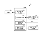
- FIG. 1 is a block diagram showing a configuration example of a vehicle operation support device according to the first embodiment.
- FIG. 2 is a diagram for explaining the wobbling of the moving body in the left-right direction.
- FIG. 3 is a diagram illustrating support for vehicle operation in the vehicle operation support device according to the first embodiment.
- FIG. 4 is a diagram illustrating an example of display by the vehicle motion support device according to the first embodiment.
- FIG. 5 is a flowchart showing an example of a processing flow in the vehicle motion support device according to the first embodiment.
- FIG. 6 is a block diagram showing a configuration example of the vehicle operation support device according to the second embodiment.
- FIG. 7 is a diagram illustrating support for vehicle operation in the vehicle operation support device according to the second embodiment.
- FIG. 8 is a block diagram showing a configuration example of the vehicle operation support device according to the third embodiment.
- FIG. 9 is a diagram illustrating support for vehicle operation in the vehicle operation support device according to the third embodiment.
- the vehicle motion support control device 40, the vehicle motion support device 1, the vehicle motion support control method, and the embodiment of the program according to the present disclosure will be described in detail with reference to the accompanying drawings below.
- the present invention is not limited to the following embodiments.
- FIG. 1 is a block diagram showing a configuration example of the vehicle operation support device 1 according to the first embodiment.
- the vehicle motion support device 1 is mounted on the vehicle.
- the vehicle motion support device 1 may be a portable device that can be used in the vehicle, in addition to the device mounted on the vehicle.
- the vehicle movement support device 1 supports the movement of the vehicle based on the degree of wobbling of the moving body in the left-right direction.
- Overtaking means that a vehicle traveling in the second lane adjacent to the first lane changes lanes and exits in front of a moving body traveling in the first lane.
- Overtaking means that a vehicle traveling in the second lane adjacent to the first lane goes out in front of a moving body traveling in the first lane without changing lanes.
- the vehicle motion support device 1 includes a camera 10 that functions as a detection unit that detects a moving body moving in front of the vehicle and outputs a detection signal to the moving body detection unit 42, a moving body recognition dictionary storage unit 20, and a moving body recognition dictionary storage unit 20. It has a head-up display (hereinafter referred to as "HUD device”) 30 and a vehicle motion support control device 40.
- HUD device head-up display
- the camera 10 captures a range including the front of the vehicle.
- a plurality of cameras 10 may be arranged.
- the camera 10 is arranged in front of the vehicle and captures video data of the periphery centered on the front of the vehicle.
- the video data is, for example, a moving image composed of an image of 30 frames per second.
- the camera 10 outputs the captured video data to the capture data acquisition unit 41 of the vehicle motion support control device 40.
- the moving object recognition dictionary storage unit 20 provides a recognition dictionary capable of collating patterns such as the shape, size, and color of each direction view such as front view, back view, and side view of a moving body including a two-wheeled vehicle and a pedestrian. I remember.
- the mobile recognition dictionary storage unit 20 is, for example, a semiconductor memory element such as a RAM (Random Access Memory) or a ROM (Read Only Memory), or a storage device such as a hard disk, an optical disk, or an external storage device via a network.
- the HUD device 30 functions as a display device that can be visually recognized by the driver of the vehicle.
- the HUD device 30 makes the information supporting the operation of the vehicle visually recognized as a virtual image in front of the driver of the vehicle.
- the HUD device 30 projects an image based on the image signal output from the projection control unit 44 of the vehicle motion support control device 40.
- the HUD device 30 may be dedicated to the vehicle motion support device 1, or may be used jointly with other systems including, for example, a navigation system.
- the HUD device 30 has a projection unit 31.
- the HUD device 30 reflects the display image projected on the projection unit 31 by a combiner or windshield (not shown) to make the driver visually recognize it as a virtual image.
- the projection unit 31 is a system that includes, for example, a liquid crystal display element or an organic EL (Electro-Luminescence) display element, and optically projects an image onto a combiner or a windshield.
- the projection unit 31 is arranged inside the dashboard of the vehicle.
- the projection unit 31 displays the display image on the display element based on the image signal from the projection control unit 44 of the vehicle motion support control device 40.
- the image display light of the display image displayed on the display surface of the display element is projected onto the combiner or the windshield through, for example, a concave mirror (not shown).
- the combiner or windshield reflects the image display light projected from the projection unit 31 and causes the driver to recognize it as a virtual image.
- the combiner or windshield is a plate-like material that is arranged so as to be convexly curved forward in the traveling direction.
- the vehicle operation support control device 40 is, for example, an arithmetic processing device composed of a CPU (Central Processing Unit), a video processing processor, and the like.
- the vehicle motion support control device 40 loads a program stored in a storage unit (not shown) into the memory and executes an instruction included in the program.
- the vehicle motion support control device 40 includes a photographing data acquisition unit 41, a moving body detection unit 42, a vehicle motion detection unit 43, and a projection control unit (motion support unit) 44.
- the vehicle motion support control device 40 includes an internal memory (not shown), and the internal memory is used for temporary storage of data in the vehicle motion support control device 40 and the like.
- the vehicle motion support control device 40 may be composed of one or a plurality of devices.
- the shooting data acquisition unit 41 acquires video data obtained by shooting a range including the front of the vehicle. More specifically, the shooting data acquisition unit 41 acquires the video data output by the camera 10 and outputs it to the moving object detection unit 42.
- the moving body detection unit 42 detects a moving body moving in front of the vehicle, and detects the degree of wobbling of the detected moving body in the left-right direction. More specifically, the moving body detection unit 42 recognizes a moving body moving in front of the vehicle by image processing from the video data acquired by the shooting data acquisition unit 41. In the present embodiment, the moving body detection unit 42 recognizes the moving body by performing image processing on the video data using the vehicle recognition dictionary stored in the moving body recognition dictionary storage unit 20. Further, the moving body detecting unit 42 detects the relative positional relationship between the vehicle and the moving body, including the distance between the vehicle and the moving body and the position of the moving body in the left-right direction. The method for recognizing a moving object may be any known method and is not limited. The moving object detection unit 42 outputs the recognition result to the projection control unit 44. Twice
- the moving body detection unit 42 detects, as the degree of wobbling of the moving body, the degree of wobbling that moves in the left-right direction in which the moving body has no linearity. Further, the moving body detection unit 42 detects the degree of wobbling due to the inclination of the moving body in the left-right direction as the degree of wobbling of the moving body.
- the distance between the vehicle and the moving body may be calculated based on, for example, the ground contact position of the moving body in the display range of video data.
- the distance between the vehicle and the moving body may be detected by, for example, a sensor installed in the vehicle including a radar.
- FIG. 2 is a diagram for explaining the wobbling of the moving body in the left-right direction.
- the moving body detecting unit 42 for example, is based on the fluctuation of the distance between the moving body and the linear reference object L such as the side line L1 or the center line L2 located on the left and right sides of the moving body in the display range of the video data. Whether or not the moving body is swaying in the left-right direction is determined based on whether or not the fluctuation of the distance is equal to or greater than the reference value.
- the moving body detection unit 42 may determine whether or not the moving body is swaying in the left-right direction depending on whether or not the change in the position of the moving body in the left-right direction is within a predetermined range on the left and right sides of the moving body. In the moving body detection unit 42, for example, in the display range of video data, when the fluctuation of the position of the moving body in the left-right direction is in the range of 50 cm or more on either the left or right side of the moving body, the moving body is swaying in the left-right direction. Detect that.
- the moving body detection unit 42 does not sway in the left-right direction when the variation of the position of the moving body in the left-right direction is less than 50 cm on either the left or right side of the moving body. Detect that.
- the moving body detection unit 42 the moving body fluctuates in the left-right direction depending on whether or not the change in the position of the moving body in the left-right direction is within a predetermined range defined by the height h of the moving body on the left and right sides of the moving body. It may be determined whether or not it is. For example, in the display range of video data, the moving body detection unit 42 wobbles the moving body in the left-right direction when the fluctuation of the position of the moving body in the left-right direction is in the range of h / 2 or more on either the left or right side of the moving body. Detects that.
- the moving body detection unit 42 wobbles the moving body in the left-right direction when the fluctuation of the position of the moving body in the left-right direction is less than h / 2 on either the left or right side of the moving body. Detect that it is not.
- the moving body detection unit 42 tracks the detected moving body in the video data according to the shape of the moving body and the like.
- the moving body detection unit 42 may stop tracking the moving body when the distance between the vehicle and the moving body continues to be separated by a threshold value or more for a predetermined time.
- the vehicle motion detection unit 43 detects that the vehicle overtakes or overtakes the moving body detected by the moving body detecting unit 42. More specifically, the vehicle motion detection unit 43 CANs the steering operation information including the operation amount of the steering operation of the vehicle, the accelerator operation information including the operation amount of the accelerator operation, and the vehicle information including the operation information of the direction indicator. Obtained from (Control Area Information) and various sensors that sense the state of the vehicle. The vehicle motion detection unit 43 detects that the vehicle overtakes or overtakes the moving body based on the vehicle information and the transition of the position of the moving body in the video data indicated by the detection result of the moving body detecting unit 42. .. The vehicle motion detection unit 43 outputs the detected detection result to the projection control unit 44.
- the vehicle motion detection unit 43 Based on the vehicle information and the transition of the position of the moving body, the vehicle motion detection unit 43, for example, causes a vehicle traveling in the second lane adjacent to the first lane to change lanes and travel in the first lane. If it is predicted that the vehicle will move in front of the moving vehicle, it detects that the vehicle is overtaking.
- the vehicle motion detection unit 43 Based on the vehicle information and the transition of the position of the moving body, the vehicle motion detection unit 43, for example, allows a vehicle traveling in the second lane adjacent to the first lane to move to the first lane without changing lanes. When it is predicted that the vehicle will come out in front of the traveling moving body, it is detected that the vehicle overtakes.
- the projection control unit 44 When the vehicle motion detection unit 43 detects that the vehicle overtakes or overtakes the moving body, the projection control unit 44 operates as a motion support unit that supports the motion according to the degree of wobbling of the moving body. .. More specifically, when the projection control unit 44 detects that the vehicle overtakes or overtakes the moving body and the moving body does not wobble in the left-right direction, or when the degree of wobbling in the left-right direction of the moving body is small, the projection control unit 44 determines. Support the first movement. The projection control unit 44 supports the second operation when it is detected that the vehicle overtakes or overtakes the moving body and the degree of wobbling of the moving body in the left-right direction is large.
- the degree of wobbling is small means that the position of the moving body fluctuates in the left-right direction to the extent that the moving body detection unit 42 detects that the moving body does not wobble in the left-right direction. Specifically, it is a case where there is a variation in the left-right direction of, for example, less than 50 cm, which is generated by the normal running of the moving body. Even if the movement in the left-right direction caused by the normal running of the moving body is derived from the value recorded in the left-right direction of the other moving body when the moving body detection unit 42 detects the other moving body. Often, it may be referred to in advance as a general value.
- the large degree of wobbling means that the position of the moving body fluctuates in the left-right direction to the extent that the moving body detecting unit 42 detects that the moving body is wobbling in the left-right direction. Specifically, this is a case where the left-right fluctuation is larger than the left-right fluctuation that occurs due to the normal running of the moving body.
- FIG. 3 is a diagram illustrating support for vehicle operation in the vehicle operation support device 1 according to the first embodiment.
- FIG. 4 is a diagram illustrating an example of display by the vehicle motion support device 1 according to the first embodiment.
- the projection control unit 44 detects that the vehicle overtakes or overtakes the moving body, and when there is no left-right wobbling of the moving body, or when the degree of left-right wobbling of the moving body is small, the first overtaking Or provide overtaking support.
- the projection control unit 44 assists the vehicle to overtake or overtake the moving body when it is detected that the vehicle overtakes or overtakes the moving body and the degree of left-right wobbling of the moving body is large.
- Second overtaking or overtaking support That is, the second overtaking or overtaking support provides overtaking or overtaking support in a state further away from the moving body as compared with the first overtaking or overtaking support.
- the first overtaking or overtaking support assists the vehicle to travel, for example, about 1.0 m away from the moving body when the vehicle overtakes or overtakes the moving body.
- This distance may be changed depending on the traveling speed or the relative speed of the moving body or the vehicle, but the distance is set so as not to affect the traveling of the moving body.
- the second overtaking or overtaking support varies depending on the degree of wobbling of the moving body, but the distance between the moving body and the vehicle is increased by about 150% to 200% with respect to the first overtaking or overtaking support, for example, the vehicle Support is provided so that the vehicle travels at a distance of, for example, 1.5 m to 2 m from the moving body.
- the projection control unit 44 may, for example, prevent the virtual image indicating the overtaking path or the overtaking path from being displayed.
- the projection control unit 44 may display a virtual image 110 indicating a normal overtaking path or overtaking path as the first overtaking or overtaking support.
- the normal overtaking route is indicated by, for example, the dashed arrow in FIG.
- the normal overtaking route is, for example, a route that passes by the side of the moving body with a distance of about 1 m between the vehicle and the moving body.
- the projection control unit 44 uses the HUD device 30 as a second overtaking or overtaking support to support overtaking or overtaking in a state farther from the moving body. More specifically, the projection control unit 44 displays a virtual image 100 indicating an overtaking route or an overtaking route as a second overtaking or overtaking support so as to travel with a longer distance between the vehicle and the moving body than usual. To do so.
- the overtaking route in this case is indicated by, for example, the solid arrow in FIG.
- the overtaking route in this case is, for example, a route that passes by the side of the moving body with a distance of about 1.5 m between the vehicle and the moving body.
- a virtual image 110 showing a normal overtaking route may be displayed.
- textual information such as "Please overtake farther than usual" may be displayed, or a voice alert may be given.
- FIG. 5 is a flowchart showing an example of a processing flow in the vehicle operation support device 1 according to the first embodiment.
- the vehicle motion support control device 40 acquires video data from the camera 10 by the shooting data acquisition unit 41.
- overtaking will be described, but the same applies to overtaking.
- the vehicle motion support control device 40 determines whether or not a moving body has been detected forward (step S101). When it is determined that the moving body detecting unit 42 performs image processing on the video data acquired by the shooting data acquisition unit 41 to detect a moving body moving in front of the vehicle (Yes in step S101), step S102. Proceed to. When the moving body detection unit 42 performs image processing on the video data acquired by the shooting data acquisition unit 41 and determines that the moving body moving in front of the vehicle is not detected (No in step S101). The process proceeds to step S107.
- the vehicle motion support control device 40 When it is determined that the moving body moving in front of the vehicle is detected (Yes in step S101), the vehicle motion support control device 40 starts detecting the degree of wobbling of the moving body by the moving body detecting unit 42 (step). S102). More specifically, the moving body detecting unit 42 starts detecting a change in the position of the detected moving body in the left-right direction. The vehicle motion support control device 40 proceeds to step S103.
- the vehicle motion support control device 40 determines whether or not the vehicle motion detection unit 43 has detected an overtaking motion with respect to the moving body (step S103). When it is determined that the vehicle motion detection unit 43 has detected an overtaking motion with respect to the moving body based on the vehicle information and the transition of the position of the moving body (Yes in step S103), the process proceeds to step S104. If it is not determined by the vehicle motion detection unit 43 that the overtaking motion with respect to the moving body has been detected based on the vehicle information and the transition of the position of the moving body (No in step S103), the process proceeds to step S107.
- the vehicle motion support control device 40 determines whether or not the degree of wobbling of the moving body is large based on the detection result of the moving body detecting unit 42. Determine (step S104).
- the vehicle operation support control device 40 proceeds to step S106. If the vehicle motion support control device 40 does not determine from the detection result of the moving body detection unit 42 that the degree of wobbling of the moving body is large (No in step S104), the vehicle operation support control device 40 proceeds to step S105.
- the vehicle motion support control device 40 executes the first overtaking support (step S105). More specifically, the projection control unit 44 prevents, for example, displaying a virtual image indicating an overtaking path. Alternatively, the projection control unit 44 may display, for example, a virtual image 110 showing a normal overtaking path shown by a broken line in FIG.
- the driver confirms the virtual image 110 shown by the broken line in FIG. 4, and overtakes the moving object by the normal overtaking route.
- the vehicle motion support control device 40 executes the second overtaking support (step S106). More specifically, the virtual image 100 indicating the overtaking route is displayed so as to travel with a longer distance between the vehicle and the moving body than usual.
- the driver confirms the virtual image 100 shown by the solid line in FIG. 4, and overtakes the moving object by the normal overtaking route.
- the driver confirms the virtual image 100 shown by the solid line in FIG. 4, and overtakes by an overtaking route that swells away from the moving body than usual.
- the vehicle motion support control device 40 determines whether or not the vehicle has finished traveling (step S107). In the vehicle motion support control device 40, for example, the shift position is "parking", the speed is zero for a predetermined time of several minutes or more, the engine is stopped, or the side brake or foot is used. When it is determined that the vehicle has finished running, such as when a brake operation is detected (Yes in step S107), the process ends. If the vehicle motion support control device 40 does not determine that the vehicle has finished traveling (No in step S107), the vehicle motion support control device 40 re-executes the process of step S101.
- the present embodiment can support the operation of the vehicle based on the degree of wobbling of the detected moving body in the left-right direction.
- the detected degree of wobbling in the left-right direction of the moving body is large, a route in which the vehicle and the moving body travel with a longer distance than usual can be displayed as the virtual image 100.
- the moving body is staggering, it is possible to support the overtaking or overtaking of the moving body more safely.
- FIG. 6 is a block diagram showing a configuration example of the vehicle operation support device 1A according to the second embodiment.
- FIG. 7 is a diagram illustrating support for vehicle operation in the vehicle operation support device 1A according to the second embodiment.
- the basic configuration of the vehicle motion support device 1A is the same as that of the vehicle motion support device 1 of the first embodiment.
- the same components as those of the vehicle operation support device 1 are designated by the same reference numerals or corresponding reference numerals, and detailed description thereof will be omitted.
- the vehicle motion support device 1A differs from the first embodiment in that the vehicle motion support device 1A has a steering operation unit 30A and that the vehicle motion support control device 40A has a steering operation support section 44A that functions as a motion support section.
- the steering operation unit 30A temporarily controls the amount of steering operation by driving the actuator based on the control signal from the steering operation support unit 44A when the vehicle is being driven by the driver.
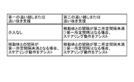
- the steering operation support unit 44A does not intervene in the steering operation as the first operation support.
- the steering operation support unit 44A sets the distance between the vehicle and the moving body to be equal to or greater than the first predetermined distance when the distance between the vehicle and the moving body is less than the first predetermined distance at the time of overtaking or overtaking. Assist the steering operation so that it becomes.
- the first predetermined interval is, for example, 50 cm.
- Assisting the steering operation means notifying the driver by displaying an image or outputting a voice so as to perform an appropriate steering operation, or outputting a control signal that assists the steering operation.
- the distance between the vehicle and the moving body can be calculated in the same manner as in the first embodiment.
- the distance between the vehicle and the moving body may be estimated from the amount of steering movement at the start of overtaking or overtaking and the relative positional relationship between the vehicle and the moving body.
- the steering operation support unit 44A supports the steering movement amount of the vehicle based on the positional relationship between the vehicle and the moving body when overtaking or overtaking the moving body. As a second operation support, the steering operation support unit 44A assists the steering operation when the distance from the moving body is less than the second predetermined interval, which is longer than the first predetermined interval, at the time of overtaking or overtaking.
- the second predetermined interval is, for example, 75 cm.
- the steering operation can be assisted so that the distance between the vehicle and the moving body is longer than usual.
- FIG. 8 is a block diagram showing a configuration example of the vehicle operation support device 1B according to the third embodiment.
- FIG. 9 is a diagram illustrating support for vehicle operation in the vehicle operation support device 1B according to the third embodiment.
- the basic configuration of the vehicle motion support device 1B is the same as that of the vehicle motion support device 1 of the first embodiment.
- the vehicle motion support device 1B is different from the first embodiment in that it has a steering operation unit 30B and that the vehicle motion support control device 40B has a steering control unit 44B that functions as a motion support unit.
- the steering operation unit 30B drives an actuator to control the amount of steering operation based on a control signal from the steering control unit 44B when the vehicle is automatically driven.
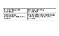
- the steering control unit 44B does not intervene in the steering operation as the first operation support. Alternatively, as the first operation support, the steering control unit 44B sets the distance from the moving body to be greater than or equal to the first predetermined distance when the distance from the moving body is less than the first predetermined distance at the time of overtaking or overtaking. , Outputs a control signal for steering operation.
- the steering control unit 44B has a second predetermined interval or more when the distance from the moving body is longer than the first predetermined interval and less than the second predetermined interval at the time of overtaking or overtaking.
- a control signal for steering operation is output so as to be.
- the steering operation can be assisted so that the distance between the vehicle and the moving body is longer than usual.
- vehicle operation support device 1 according to the present disclosure has been described so far, it may be implemented in various different forms other than the above-described embodiment.
- Each component of the vehicle motion support device 1 shown is a functional concept, and does not necessarily have to be physically configured as shown in the figure. That is, the specific form of each device is not limited to the one shown in the figure, and all or part of each device is functionally or physically dispersed or integrated in an arbitrary unit according to the processing load and usage status of each device. You may.
- the configuration of the vehicle operation support device 1 is realized by, for example, a program loaded in a memory as software.
- a program loaded in a memory as software.
- it has been described as a functional block realized by cooperation of these hardware or software. That is, these functional blocks can be realized in various forms by hardware only, software only, or a combination thereof.
- the moving object is detected from the video data captured by the camera 10, but the method of detecting the moving object is not limited to this.
- a sensor may detect a moving object in front of the vehicle.
- various methods such as a combination of a plurality of types of sensors such as an infrared sensor, an ultrasonic sensor, a millimeter wave sensor, and a sensor by image recognition can be applied.
- the above-mentioned moving body detection unit may determine the type and attributes of the moving body and the occupants riding on the moving body by recognizing the moving body. For example, if the type of mobile is a children's bicycle, or if the occupant of the mobile is an elderly person, the second motion support may be further separated from the mobile when overtaking or overtaking.
- image processing is performed on the video data to remove obstacles that affect overtaking or overtaking of other vehicles, such as oncoming vehicles, diagonal lines, medians, and roadsides. It may have a determination unit that recognizes and determines whether or not overtaking or overtaking is possible. When the judgment unit determines that overtaking or overtaking is difficult due to the presence of an obstacle, the motion support unit notifies the driver that overtaking or overtaking is difficult, or overtakes unreasonably. Alternatively, the operation of the vehicle may be assisted so as not to overtake.
- vehicle motion support control device vehicle motion support device, vehicle motion support control method and program of the present disclosure can be used, for example, in a vehicle motion support device for supporting the safety of the vehicle and its surroundings.
- Vehicle motion support device 10 Camera (detector) 20 Mobile recognition dictionary storage unit 30 HUD device (display device) 40 Vehicle motion support control device 41 Shooting data acquisition unit 42 Moving object detection unit 43 Vehicle motion detection unit 44 Projection control unit (motion support unit)
Landscapes
- Physics & Mathematics (AREA)
- General Physics & Mathematics (AREA)
- Traffic Control Systems (AREA)
Abstract
移動体に対する追い越し時および追い抜き時の安全性を高めること。車両の前方を移動している移動体を検出し、検出した移動体の左右方向のふらつき度合いを検出する、移動体検出部42と、車両が、移動体検出部42が検出した移動体に対する追い越しまたは追い抜きを行うことを検出する車両動作検出部43と、車両動作検出部43が、移動体検出部42が検出した移動体に対する追い越しまたは追い抜きを行うことを検出した場合、移動体検出部42が検出した移動体の左右方向のふらつき度合いに基づき、車両の動作を支援する動作支援部として機能する投影制御部44とを備える。
Description
本発明は、車両動作支援制御装置、車両動作支援装置、車両動作支援制御方法およびプログラムに関する。
前方の障害物の側方に接触危険領域を設定し、接触危険領域への自車両の侵入が検知されたときに警報装置を作動させる技術が知られている(例えば、特許文献1参照)。
例えば、高齢者などが運転する、オートバイおよび自転車のような二輪車や、二輪車の積み荷などの状態によって、二輪車がふらつきながら走行している場合がある。また、歩行者であっても、身体の状態または周囲の状況などによってはふらつきながら歩行している場合もある。
特許文献1の技術は、障害物に、所定の危険領域を設定している。しかしながら、ふらつきながら走行している二輪車または歩行者などの移動体に対する追い越し時および追い抜き時には、あらかじめ設定した危険領域では対応が不十分になるおそれがある。
本開示は、上記に鑑みてなされたものであって、移動体に対する追い越し時および追い抜き時の安全性を高めることを目的とする。
上述した課題を解決し、目的を達成するために、本開示に係る車両動作支援制御装置は、車両の前方を移動している移動体を検出し、検出した移動体の左右方向のふらつき度合いを検出する、移動体検出部と、前記車両が、前記移動体検出部が検出した移動体に対する追い越しまたは追い抜きを行うことを検出する車両動作検出部と、前記車両動作検出部が、前記移動体に対する追い越しまたは追い抜きを行うことを検出した場合、前記移動体の左右方向のふらつき度合いに基づき、前記車両の動作を支援する動作支援部と、を備える。
本開示に係る車両動作支援装置は、上記の車両動作支援制御装置と、車両の前方を移動している移動体を検出して前記移動体検出部に検出信号を出力する検出部と、を備える。
本開示に係る車両動作支援制御方法は、車両の前方を移動している移動体を検出し、検出した移動体の左右方向のふらつき度合いを検出する移動体検出ステップと、前記車両が、前記移動体検出ステップによって検出された移動体に対する追い越しまたは追い抜きを行うことを検出する車両動作検出ステップと、前記車両動作検出ステップにおいて、前記移動体に対する追い越しまたは追い抜きを行うことを検出した場合、前記移動体の左右方向のふらつき度合いに基づき、前記車両の動作を支援する動作支援ステップと、を含む。
本開示に係るプログラムは、車両の前方を移動している移動体を検出し、検出した移動体の左右方向のふらつき度合いを検出する移動体検出ステップと、前記車両が、前記移動体検出ステップによって検出された移動体に対する追い越しまたは追い抜きを行うことを検出する車両動作検出ステップと、前記車両動作検出ステップにおいて、前記移動体に対する追い越しまたは追い抜きを行うことを検出した場合、前記移動体の左右方向のふらつき度合いに基づき、前記車両の動作を支援する動作支援ステップと、を車両動作支援装置として動作するコンピュータに実行させる。
本開示によれば、移動体に対する追い越し時および追い抜き時の安全性を高めることができるという効果を奏する。
以下に添付図面を参照して、本開示に係る車両動作支援制御装置40、車両動作支援装置1、車両動作支援制御方法およびプログラムの実施形態を詳細に説明する。なお、以下の実施形態により本発明が限定されるものではない。
[第一実施形態]
<車両動作支援装置>
図1は、第一実施形態に係る車両動作支援装置1の構成例を示すブロック図である。車両動作支援装置1は、車両に搭載されている。車両動作支援装置1は、車両に載置されているものに加えて、可搬型で車両において利用可能な装置であってもよい。車両動作支援装置1は、例えば、二輪車または歩行者などの移動体に対する追い越しまたは追い抜きを行う場合、移動体の左右方向のふらつき度合いに基づき、車両の動作を支援する。
<車両動作支援装置>
図1は、第一実施形態に係る車両動作支援装置1の構成例を示すブロック図である。車両動作支援装置1は、車両に搭載されている。車両動作支援装置1は、車両に載置されているものに加えて、可搬型で車両において利用可能な装置であってもよい。車両動作支援装置1は、例えば、二輪車または歩行者などの移動体に対する追い越しまたは追い抜きを行う場合、移動体の左右方向のふらつき度合いに基づき、車両の動作を支援する。
追い越しとは、第一車線に隣接する第二車線を走行している車両が、車線変更して、第一車線を走行する移動体の前方に出ることをいう。
追い抜きとは、第一車線に隣接する第二車線を走行している車両が、車線変更せずに、第一車線を走行する移動体の前方に出ることをいう。
車両動作支援装置1は、車両の前方を移動している移動体を検出して移動体検出部42に検出信号を出力する検出部として機能するカメラ10と、移動体認識辞書記憶部20と、ヘッドアップディスプレイ(以下、「HUD装置」という。)30と、車両動作支援制御装置40とを有する。
カメラ10は、車両の前方を含む範囲を撮影する。カメラ10は、複数配置されていてもよい。本実施形態では、カメラ10は、車両の前方に配置され、車両の前方を中心とした周辺の映像データを撮影する。映像データは、例えば毎秒30フレームの画像から構成される動画像である。カメラ10は、撮影した映像データを車両動作支援制御装置40の撮影データ取得部41へ出力する。
移動体認識辞書記憶部20は、例えば、二輪車および歩行者を含む移動体の正面視、背面視、側面視などの各方面視の形状、大きさ、色などのパターンを照合可能な認識辞書を記憶している。移動体認識辞書記憶部20は、例えば、RAM(Random Access Memory)、ROM(Read Only Memory)などの半導体メモリ素子、または、ハードディスク、光ディスク、ネットワークを介した外部記憶装置などの記憶装置である。
HUD装置30は、車両の運転者が視認できる表示装置として機能する。HUD装置30は、車両の運転者の前方において、車両の動作を支援する情報を、虚像として視認させる。HUD装置30は、車両動作支援制御装置40の投影制御部44から出力された映像信号に基づいて映像を投影する。HUD装置30は、車両動作支援装置1に専用のものであっても、例えば、ナビゲーションシステムを含む他のシステムと共同で使用するものであってもよい。
HUD装置30は、投影部31を有する。HUD装置30は、投影部31に投影された表示映像を、図示しないコンバイナまたはウィンドシールドで反射させ運転者に虚像として視認させる。
投影部31は、例えば、液晶表示素子または有機EL(Electro‐Luminescence)表示素子含み、光学的にコンバイナまたはウィンドシールドに映像を投射させるシステムである。本実施形態では、投影部31は、車両のダッシュボードの内部に配置されている。投影部31は、車両動作支援制御装置40の投影制御部44からの映像信号に基づいて表示素子に表示映像を表示する。表示素子の表示面に表示された表示映像の映像表示光は、例えば、図示しない凹面鏡などを介して、コンバイナまたはウィンドシールドに投影される。
コンバイナまたはウィンドシールドは、投影部31から投影された映像表示光を反射させ運転者に虚像として認識させる。コンバイナまたはウィンドシールドは、進行方向前方に凸状に湾曲して配置される板状材である。
車両動作支援制御装置40は、例えば、CPU(Central Processing Unit)や映像処理用プロセッサなどで構成された演算処理装置である。車両動作支援制御装置40は、図示しない記憶部に記憶されているプログラムをメモリにロードして、プログラムに含まれる命令を実行する。車両動作支援制御装置40は、撮影データ取得部41と、移動体検出部42と、車両動作検出部43と、投影制御部(動作支援部)44とを有する。車両動作支援制御装置40には図示しない内部メモリが含まれ、内部メモリは車両動作支援制御装置40におけるデータの一時記憶などに用いられる。車両動作支援制御装置40は、一または複数の装置で構成されていてもよい。
撮影データ取得部41は、車両の前方を含む範囲を撮影した映像データを取得する。より詳しくは、撮影データ取得部41は、カメラ10が出力した映像データを取得して、移動体検出部42に出力する。
移動体検出部42は、車両の前方を移動している移動体を検出し、検出した移動体の左右方向のふらつき度合いを検出する。より詳しくは、移動体検出部42は、撮影データ取得部41が取得した映像データから画像処理によって、車両の前方を移動する移動体を認識する。本実施形態では、移動体検出部42は、映像データに、移動体認識辞書記憶部20が記憶した車両認識辞書を使用して、画像処理を行って移動体を認識する。さらに、移動体検出部42は、車両と移動体との間隔、移動体の左右方向の位置を含む、車両と移動体との相対的な位置関係を検出する。移動体を認識する方法は、公知の方法であればよく、限定されない。移動体検出部42は、認識結果を投影制御部44に出力する。
移動体検出部42は、移動体のふらつき度合いとして、移動体の走行に直線性がない左右方向に移動するふらつきの度合いを検出する。また、移動体検出部42は、移動体のふらつき度合いとして、移動体の左右方向の傾きによるふらつき度合いを検出する。
車両と移動体との間隔は、例えば、映像データの表示範囲における、移動体の接地位置によって算出してもよい。または、車両と移動体との間隔は、例えば、車両に設置された、レーダなどを含むセンサによって検出してもよい。
図2は、移動体の左右方向のふらつきを説明する図である。移動体検出部42は、例えば、映像データの表示範囲において、移動体の左右に位置する、側線L1または中央線L2などの直線状の基準物Lと移動体との距離の変動に基づいて、距離の変動が基準値以上であるか否かによって、移動体が左右方向にふらついているか否かを判定する。
移動体検出部42は、移動体の左右方向の位置の変動が、移動体の左右において所定範囲であるか否かによって、移動体が左右方向にふらついているか否かを判定してもよい。移動体検出部42は、例えば、映像データの表示範囲において、移動体の左右方向の位置の変動が、移動体の左右いずれか50cm以上の範囲である場合、移動体が左右方向にふらついていることを検出する。移動体検出部42は、例えば、映像データの表示範囲において、移動体の左右方向の位置の変動が、移動体の左右いずれか50cm未満の範囲である場合、移動体が左右方向にふらついていないことを検出する。
移動体検出部42は、移動体の左右方向の位置の変動が、移動体の左右において、移動体の高さhで規定される所定範囲であるか否かによって、移動体が左右方向にふらついているか否かを判定してもよい。移動体検出部42は、例えば、映像データの表示範囲において、移動体の左右方向の位置の変動が、移動体の左右いずれかh/2以上の範囲である場合、移動体が左右方向にふらついていることを検出する。移動体検出部42は、例えば、映像データの表示範囲において、移動体の左右方向の位置の変動が、移動体の左右いずれかh/2未満の範囲である場合、移動体が左右方向にふらついていないことを検出する。
移動体検出部42は、移動体の形状などによって、映像データにおいて、検出した移動体を追尾する。移動体検出部42は、車両と移動体との間隔が閾値以上離れた状態が所定時間継続した場合、移動体に対する追尾を停止してもよい。
車両動作検出部43は、車両が、移動体検出部42が検出した移動体に対する追い越しまたは追い抜きを行うことを検出する。より詳しくは、車両動作検出部43は、車両のステアリング操作の動作量を含むステアリング操作情報、アクセル操作の動作量を含むアクセル操作情報、および、方向指示器の操作情報を含む車両情報を、CAN(Controller Area Network)や車両の状態をセンシングする各種センサなどから取得する。車両動作検出部43は、車両情報と、移動体検出部42の検出結果が示す、映像データにおける移動体の位置の推移とに基づいて、車両が移動体に対する追い越しまたは追い抜きを行うことを検出する。車両動作検出部43は、検出した検出結果を投影制御部44に出力する。
車両動作検出部43は、車両情報と移動体の位置の推移とに基づいて、例えば、第一車線に隣接する第二車線を走行している車両が、車線変更して、第一車線を走行する移動体の前方に出ることが予測される場合、車両が追い越しを行うことを検出する。
車両動作検出部43は、車両情報と移動体の位置の推移とに基づいて、例えば、第一車線に隣接する第二車線を走行している車両が、車線変更せずに、第一車線を走行する移動体の前方に出ることが予測される場合、車両が追い抜きを行うことを検出する。
投影制御部44は、車両動作検出部43によって、車両が移動体に対する追い越しまたは追い抜きを行うことが検出された場合に、移動体のふらつき度合いに応じて、動作を支援する動作支援部として動作する。より詳しくは、投影制御部44は、車両が移動体に対する追い越しまたは追い抜きを行うことが検出され、移動体の左右方向のふらつきがない場合、または、移動体の左右方向のふらつき度合いが小さい場合、第一の動作の支援を行う。投影制御部44は、車両が移動体に対する追い越しまたは追い抜きを行うことが検出され、移動体の左右方向のふらつき度合いが大きい場合、第二の動作の支援を行う。
ふらつき度合いが小さいとは、移動体検出部42によって、移動体が左右方向にふらついていないと検出される程度に、移動体の左右方向の位置の変動があることをいう。具体的には、移動体の通常の走行によって発生する、例えば50cm未満程度の左右方向の変動がある場合である。移動体の通常の走行によって発生する左右方向の変動は、移動体検出部42が、他の移動体を検出したときに、他の移動体の左右方向の変動を記録した値から導出してもよく、一般的な値として予め参照可能としていてもよい。
ふらつき度合いが大きいとは、移動体検出部42によって、移動体が左右方向にふらついていると検出される程度に、移動体の左右方向の位置の変動があることをいう。具体的には、移動体の通常の走行によって発生する程度の左右方向の変動に比べて左右の変動が大きい場合である。
図3、図4を用いて、動作支援部としての投影制御部44による動作の支援について詳しく説明する。図3は、第一実施形態に係る車両動作支援装置1における車両の動作の支援を説明する図である。図4は、第一実施形態に係る車両動作支援装置1による表示の一例を説明する図である。
投影制御部44は、車両が移動体に対する追い越しまたは追い抜きを行うことが検出され、移動体の左右方向のふらつきがない場合、または、移動体の左右方向のふらつき度合いが小さい場合、第一の追い越しまたは追い抜き支援を行う。投影制御部44は、車両が移動体に対する追い越しまたは追い抜きを行うことが検出され、移動体の左右方向のふらつき度合いが大きい場合、移動体からより離れた状態で追い越しまたは追い抜きを行うように支援する、第二の追い越しまたは追い抜き支援を行う。つまり、第二の追い越しまたは追い抜き支援とは、第一の追い越しまたは追い抜き支援に比べて、移動体からさらに離れた状態での追い越しまたは追い抜き支援を行う。
図4に示すように、第一の追い越しまたは追い抜き支援は、車両が移動体を追い越しまたは追い抜きを行う際に、車両が移動体から例えば1.0m程度離れて走行するような支援を行う。この距離は、移動体や車両の走行速度や相対速度によって変化させてもよいが、移動体の走行に影響のない程度の距離が設定される。第二の追い越しまたは追い抜き支援は、移動体のふらつき度合いによっても異なるが、第一の追い越しまたは追い抜き支援に対して、150%から200%程度移動体と車両との距離を離間させ、例えば車両が移動体から例えば1.5mから2m程度離れて走行するような支援を行う。
投影制御部44は、第一の追い越しまたは追い抜き支援として、例えば、追い越し経路または追い抜き経路を示す虚像が表示されないようにしてもよい。投影制御部44は、第一の追い越しまたは追い抜き支援として、通常の追い越し経路または追い抜き経路を示す虚像110が表示されるようにしてもよい。通常の追い越し経路は、例えば、図4における破線の矢印で表示される。通常の追い越し経路は、例えば、車両と移動体との間隔を1m程度とって、移動体の側方を通過する経路である。
投影制御部44は、第二の追い越しまたは追い抜き支援として、HUD装置30を用いて、移動体からより離れた状態で追い越しまたは追い抜きを行うように支援する。より詳しくは、投影制御部44は、第二の追い越しまたは追い抜き支援として、車両と移動体との間隔を通常より長くとって走行するように、追い越し経路または追い抜き経路を示す虚像100が表示されるようにする。この場合の追い越し経路は、例えば、図4における実線の矢印で表示される。この場合の追い越し経路は、例えば、車両と移動体との間隔を1.5m程度とって、移動体の側方を通過する経路である。また、比較のために、通常の追い越し経路を示す虚像110を表示してもよい。さらにまた、「いつもより離れて追い越してください」との文字情報の表示や、音声による注意喚起が行われるようにしてもよい。
次に、図5を用いて、車両動作支援装置1の車両動作支援制御装置40における処理の流れについて説明する。図5は、第一実施形態に係る車両動作支援装置1における処理の流れの一例を示すフローチャートである。
車両動作支援装置1の起動中、車両動作支援制御装置40は、撮影データ取得部41によって、カメラ10から映像データを取得する。図5に示すフローチャートでは、追い越しについて説明するが、追い抜きについても同様である。
車両動作支援制御装置40は、前方に移動体を検出したか否かを判定する(ステップS101)。移動体検出部42によって、撮影データ取得部41が取得した映像データに画像処理を行って、車両の前方を移動している移動体を検出したと判定する場合(ステップS101でYes)、ステップS102へ進む。移動体検出部42によって、撮影データ取得部41が取得した映像データに画像処理を行って、車両の前方を移動している移動体を検出していないと判定した場合(ステップS101でNo)、ステップS107へ進む。
車両の前方を移動している移動体を検出したと判定する場合(ステップS101でYes)、車両動作支援制御装置40は、移動体検出部42によって、移動体のふらつき度合いを検出開始する(ステップS102)。より詳しくは、移動体検出部42によって、検出された移動体について、左右方向の位置の変動の検出を開始する。車両動作支援制御装置40は、ステップS103に進む。
車両動作支援制御装置40は、車両動作検出部43によって、移動体に対する追い越し動作を検出したか否かを判定する(ステップS103)。車両動作検出部43によって、車両情報と移動体の位置の推移とに基づいて、移動体に対する追い越し動作を検出したと判定する場合(ステップS103でYes)、ステップS104へ進む。車両動作検出部43によって、車両情報と移動体の位置の推移とに基づいて、移動体に対する追い越し動作を検出したと判定しない場合(ステップS103でNo)、ステップS107へ進む。
移動体に対する追い越し動作を検出したと判定する場合(ステップS103でYes)、車両動作支援制御装置40は、移動体検出部42の検出結果に基づいて、移動体のふらつき度合いが大きいか否かを判定する(ステップS104)。車両動作支援制御装置40は、移動体検出部42の検出結果から、移動体のふらつき度合いが大きいと判定する場合(ステップS104でYes)、ステップS106へ進む。車両動作支援制御装置40は、移動体検出部42の検出結果から、移動体のふらつき度合いが大きいと判定しない場合(ステップS104でNo)、ステップS105へ進む。
移動体のふらつき度合いが大きいと判定しない場合(ステップS104でNo)、車両動作支援制御装置40は、第一の追い越し支援を実行する(ステップS105)。より詳しくは、投影制御部44によって、例えば、追い越し経路を示す虚像が表示されないようにする。または、投影制御部44によって、例えば、図4において破線で示される、通常の追い越し経路を示す虚像110が表示されるようにしてもよい。
運転者は、例えば、図4において破線で示される虚像110を確認して、通常の追い越し経路で、移動体に対する追い越しをする。
移動体のふらつき度合いが大きいと判定する場合(ステップS104でYes)、車両動作支援制御装置40は、第二の追い越し支援を実行する(ステップS106)。より詳しくは、車両と移動体との間隔を通常より長くとって走行するように、追い越し経路を示す虚像100が表示されるようにする。
運転者は、例えば、図4において実線で示される虚像100を確認して、通常の追い越し経路で、移動体に対する追い越しをする。
または、運転者は、例えば、図4において実線で示される虚像100を確認して、通常より移動体から離れるように膨らんだ追い越し経路で追い越しをする。
車両動作支援制御装置40は、走行終了か否かを判定する(ステップS107)。車両動作支援制御装置40は、例えば、シフトポジションが「パーキング」であること、または、数分間程度の所定時間以上の時間、速度がゼロであること、または、エンジン停止、または、サイドブレーキやフットブレーキの操作などを検出した場合など、走行終了と判定した場合(ステップS107でYes)、処理を終了する。車両動作支援制御装置40は、走行終了と判定しない場合(ステップS107でNo)、ステップS101の処理を再度実行する。
上述したように、本実施形態は、車両が移動体に対する追い越しまたは追い抜きを行うことを検出した場合、検出した移動体の左右方向のふらつき度合いに基づき、車両の動作を支援することができる。本実施形態では、検出した移動体の左右方向のふらつき度合いが大きい場合、車両と移動体との間隔を通常より長くとって走行するような経路を虚像100として表示することができる。本実施形態によれば、移動体がふらついている場合、移動体に対する追い越しまたは追い抜きを、より安全に行うように支援できる。
[第二実施形態]
図6、図7を参照しながら、本実施形態に係る車両動作支援装置1Aについて説明する。図6は、第二実施形態に係る車両動作支援装置1Aの構成例を示すブロック図である。図7は、第二実施形態に係る車両動作支援装置1Aにおける車両の動作の支援を説明する図である。車両動作支援装置1Aは、基本的な構成は第一実施形態の車両動作支援装置1と同様である。以下の説明においては、車両動作支援装置1と同様の構成要素には、同一の符号または対応する符号を付し、その詳細な説明は省略する。車両動作支援装置1Aは、ステアリング操作部30Aを有する点と、動作支援部として機能する、ステアリング操作支援部44Aを車両動作支援制御装置40Aが有する点とが、第一実施形態と異なる。
図6、図7を参照しながら、本実施形態に係る車両動作支援装置1Aについて説明する。図6は、第二実施形態に係る車両動作支援装置1Aの構成例を示すブロック図である。図7は、第二実施形態に係る車両動作支援装置1Aにおける車両の動作の支援を説明する図である。車両動作支援装置1Aは、基本的な構成は第一実施形態の車両動作支援装置1と同様である。以下の説明においては、車両動作支援装置1と同様の構成要素には、同一の符号または対応する符号を付し、その詳細な説明は省略する。車両動作支援装置1Aは、ステアリング操作部30Aを有する点と、動作支援部として機能する、ステアリング操作支援部44Aを車両動作支援制御装置40Aが有する点とが、第一実施形態と異なる。
ステアリング操作部30Aは、車両が運転者によって運転されている時に、ステアリング操作支援部44Aからの制御信号に基づいて、アクチュエータを駆動してステアリングの動作量を一時的に制御する。
ステアリング操作支援部44Aは、第一の動作支援として、ステアリング操作に介入しない。または、ステアリング操作支援部44Aは、第一の動作支援として、追い越しまたは追い抜き時に、車両と移動体との間隔が第一所定間隔未満となる場合、移動体との間隔が第一所定間隔以上となるように、ステアリング操作をアシストする。第一所定間隔は、例えば、50cmである。
ステアリング操作をアシストするとは、運転者に対して、適切なステアリング操作を行うように、画像の表示または音声の出力によって知らせること、または、ステアリング操作をアシストする制御信号を出力することをいう。
車両と移動体との間隔は、第一実施形態と同様に算出可能である。または、車両と移動体との間隔は、追い越しまたは追い抜きの開始時のステアリングの動作量と、車両と移動体との相対的な位置関係とから推測してもよい。
ステアリング操作支援部44Aは、移動体を追い越しまたは追い抜きするときの車両と移動体との位置関係に基づき、車両のステアリング動作量を支援する。ステアリング操作支援部44Aは、第二の動作支援として、追い越しまたは追い抜き時に、移動体との間隔が第一所定間隔より長い第二所定間隔未満となる場合、ステアリング操作をアシストする。第二所定間隔は、例えば、75cmである。
上述したように、本実施形態は、検出した移動体の左右方向のふらつき度合いが大きい場合、車両と移動体との間隔を通常より長くとって走行するように、ステアリング操作をアシストできる。
[第三実施形態]
図8、図9を参照しながら、本実施形態に係る車両動作支援装置1Bについて説明する。図8は、第三実施形態に係る車両動作支援装置1Bの構成例を示すブロック図である。図9は、第三実施形態に係る車両動作支援装置1Bにおける車両の動作の支援を説明する図である。車両動作支援装置1Bは、基本的な構成は第一実施形態の車両動作支援装置1と同様である。車両動作支援装置1Bは、ステアリング操作部30Bを有する点と、車両動作支援制御装置40Bが、動作支援部として機能する、ステアリング制御部44Bを有する点とが、第一実施形態と異なる。
図8、図9を参照しながら、本実施形態に係る車両動作支援装置1Bについて説明する。図8は、第三実施形態に係る車両動作支援装置1Bの構成例を示すブロック図である。図9は、第三実施形態に係る車両動作支援装置1Bにおける車両の動作の支援を説明する図である。車両動作支援装置1Bは、基本的な構成は第一実施形態の車両動作支援装置1と同様である。車両動作支援装置1Bは、ステアリング操作部30Bを有する点と、車両動作支援制御装置40Bが、動作支援部として機能する、ステアリング制御部44Bを有する点とが、第一実施形態と異なる。
ステアリング操作部30Bは、車両が自動運転されている時に、ステアリング制御部44Bからの制御信号に基づいて、アクチュエータを駆動してステアリングの動作量を制御する。
ステアリング制御部44Bは、第一の動作支援として、ステアリング操作に介入しない。または、ステアリング制御部44Bは、第一の動作支援として、追い越しまたは追い抜き時に、移動体との間隔が第一所定間隔未満となる場合、移動体との間隔が第一所定間隔以上となるように、ステアリング操作を行う制御信号を出力する。
ステアリング制御部44Bは、第二の動作支援として、追い越しまたは追い抜き時に、移動体との間隔が第一所定間隔より長い第二所定間隔未満となる場合、移動体との間隔が第二所定間隔以上となるように、ステアリング操作を行う制御信号を出力する。
上述したように、本実施形態は、検出した移動体の左右方向のふらつき度合いが大きい場合、車両と移動体との間隔を通常より長くとって走行するように、ステアリング操作をアシストできる。
さて、これまで本開示に係る車両動作支援装置1について説明したが、上述した実施形態以外にも種々の異なる形態にて実施されてよいものである。
図示した車両動作支援装置1の各構成要素は、機能概念的なものであり、必ずしも物理的に図示の如く構成されていなくてもよい。すなわち、各装置の具体的形態は、図示のものに限られず、各装置の処理負担や使用状況などに応じて、その全部または一部を任意の単位で機能的または物理的に分散または統合してもよい。
車両動作支援装置1の構成は、例えば、ソフトウェアとして、メモリにロードされたプログラムなどによって実現される。上記実施形態では、これらのハードウェアまたはソフトウェアの連携によって実現される機能ブロックとして説明した。すなわち、これらの機能ブロックについては、ハードウェアのみ、ソフトウェアのみ、または、それらの組み合わせによって種々の形で実現できる。
上記に記載した構成要素には、当業者が容易に想定できるもの、実質的に同一のものを含む。さらに、上記に記載した構成は適宜組み合わせが可能である。また、本発明の要旨を逸脱しない範囲において構成の種々の省略、置換または変更が可能である。
上記では、カメラ10が撮影した映像データから移動体を検出するものとして説明したが、移動体を検出する方法は、これに限定されない。例えば、センサによって、車両の前方の移動体を検出してもよい。センサは、例えば、赤外線センサ、超音波センサ、ミリ波センサ、画像認識によるセンサ等、複数方式のセンサの組合せなど様々な方式が適用可能である。
上述した移動体検出部は、移動体の認識によって、移動体の種類や移動体に乗っている乗員を種類や属性を判断してもよい。例えば、移動体の種類が子供用自転車である場合や、移動体の乗員が高齢者である場合は、追い越しまたは追い抜き時に、第二の動作支援を移動体からさらに離れるようにしてもよい。
上記の車両の動作支援に加えて、映像データに画像処理を行って、例えば、対向車、斜線、分離帯、および、道路端などのような、他車両に対する追い越しまたは追い抜きに影響する障害物を認識して、追い越しまたは追い抜きの可否を判定する、判定部を有してもよい。判定部によって、障害物の存在により、追い越しまたは追い抜きが困難であると判定される場合、動作支援部は、運転者に対して、追い越しまたは追い抜きが困難である旨を通知したり、無理な追い越しまたは追い抜きを行わないように、車両の動作をアシストしたりしてもよい。
本開示の車両動作支援制御装置、車両動作支援装置、車両動作支援制御方法およびプログラムは、例えば車両及び車両の周辺の安全を支援するための車両動作支援装置に使用可能である。
1 車両動作支援装置
10 カメラ(検出部)
20 移動体認識辞書記憶部
30 HUD装置(表示装置)
40 車両動作支援制御装置
41 撮影データ取得部
42 移動体検出部
43 車両動作検出部
44 投影制御部(動作支援部)
10 カメラ(検出部)
20 移動体認識辞書記憶部
30 HUD装置(表示装置)
40 車両動作支援制御装置
41 撮影データ取得部
42 移動体検出部
43 車両動作検出部
44 投影制御部(動作支援部)
Claims (7)
- 車両の前方を移動している移動体を検出し、検出した移動体の左右方向のふらつき度合いを検出する、移動体検出部と、
前記車両が、前記移動体検出部が検出した移動体に対する追い越しまたは追い抜きを行うことを検出する車両動作検出部と、
前記車両動作検出部が、前記移動体に対する追い越しまたは追い抜きを行うことを検出した場合、前記移動体の左右方向のふらつき度合いに基づき、前記車両の動作を支援する動作支援部と、
を備える、車両動作支援制御装置。 - 前記動作支援部は、前記移動体の左右方向のふらつき度合いが、前記移動体の通常の走行時に発生するふらつきより大きい場合、前記移動体の通常の走行時における追い越しまたは追い抜きの支援に比べて前記移動体から離れた状態で追い越しまたは追い抜きを行うように支援する、
請求項1に記載の車両動作支援制御装置。 - 前記動作支援部は、前記車両の運転者が視認できる表示装置を用いて、追い越しまたは追い抜きを行うように支援する、
請求項2に記載の車両動作支援制御装置。 - 前記動作支援部は、前記移動体を追い越しまたは追い抜きするときの前記車両と前記移動体との位置関係に基づき前記車両のステアリング動作量を支援する、
請求項2に記載の車両動作支援制御装置。 - 請求項1から4のいずれか一項に記載の車両動作支援制御装置と、
車両の前方を移動している移動体を検出して前記移動体検出部に検出信号を出力する検出部と、
を備える、車両動作支援装置。 - 車両の前方を移動している移動体を検出し、検出した移動体の左右方向のふらつき度合いを検出する移動体検出ステップと、
前記車両が、前記移動体検出ステップによって検出された移動体に対する追い越しまたは追い抜きを行うことを検出する車両動作検出ステップと、
前記車両動作検出ステップにおいて、前記移動体に対する追い越しまたは追い抜きを行うことを検出した場合、前記移動体の左右方向のふらつき度合いに基づき、前記車両の動作を支援する動作支援ステップと、
を含むことを特徴とする車両動作支援制御方法。 - 車両の前方を移動している移動体を検出し、検出した移動体の左右方向のふらつき度合いを検出する移動体検出ステップと、
前記車両が、前記移動体検出ステップによって検出された移動体に対する追い越しまたは追い抜きを行うことを検出する車両動作検出ステップと、
前記車両動作検出ステップにおいて、前記移動体に対する追い越しまたは追い抜きを行うことを検出した場合、前記移動体の左右方向のふらつき度合いに基づき、前記車両の動作を支援する動作支援ステップと、
を車両動作支援制御装置として動作するコンピュータに実行させるためのプログラム。
Applications Claiming Priority (2)
| Application Number | Priority Date | Filing Date | Title |
|---|---|---|---|
| JP2020-046523 | 2020-03-17 | ||
| JP2020046523A JP2021149291A (ja) | 2020-03-17 | 2020-03-17 | 車両動作支援制御装置、車両動作支援装置、車両動作支援制御方法およびプログラム |
Publications (1)
| Publication Number | Publication Date |
|---|---|
| WO2021186783A1 true WO2021186783A1 (ja) | 2021-09-23 |
Family
ID=77771157
Family Applications (1)
| Application Number | Title | Priority Date | Filing Date |
|---|---|---|---|
| PCT/JP2020/040197 Ceased WO2021186783A1 (ja) | 2020-03-17 | 2020-10-27 | 車両動作支援制御装置、車両動作支援装置、車両動作支援制御方法およびプログラム |
Country Status (2)
| Country | Link |
|---|---|
| JP (1) | JP2021149291A (ja) |
| WO (1) | WO2021186783A1 (ja) |
Cited By (1)
| Publication number | Priority date | Publication date | Assignee | Title |
|---|---|---|---|---|
| US20240382644A1 (en) * | 2021-09-24 | 2024-11-21 | Mitsubishi Electric Corporation | Disinfecting and virus inactivating device, air-conditioning apparatus including disinfecting and virus inactivating device thereon, and disinfection and virus inactivation method |
Citations (5)
| Publication number | Priority date | Publication date | Assignee | Title |
|---|---|---|---|---|
| JP2010070061A (ja) * | 2008-09-18 | 2010-04-02 | Toyota Motor Corp | 車両走行支援装置 |
| JP2018142297A (ja) * | 2017-02-27 | 2018-09-13 | パナソニック インテレクチュアル プロパティ コーポレーション オブ アメリカPanasonic Intellectual Property Corporation of America | 情報処理装置およびプログラム |
| WO2019063352A1 (en) * | 2017-09-28 | 2019-04-04 | Connaught Electronics Ltd. | METHOD FOR ASSISTING DRIVER OF MOTOR VEHICLE WHEN OVERPASSING OBJECT AND DRIVER ASSISTANCE SYSTEM |
| JP2019156224A (ja) * | 2018-03-14 | 2019-09-19 | 本田技研工業株式会社 | 車両制御装置、車両制御方法、およびプログラム |
| JP2019185113A (ja) * | 2018-04-02 | 2019-10-24 | 本田技研工業株式会社 | 車両制御装置、車両制御方法、およびプログラム |
-
2020
- 2020-03-17 JP JP2020046523A patent/JP2021149291A/ja active Pending
- 2020-10-27 WO PCT/JP2020/040197 patent/WO2021186783A1/ja not_active Ceased
Patent Citations (5)
| Publication number | Priority date | Publication date | Assignee | Title |
|---|---|---|---|---|
| JP2010070061A (ja) * | 2008-09-18 | 2010-04-02 | Toyota Motor Corp | 車両走行支援装置 |
| JP2018142297A (ja) * | 2017-02-27 | 2018-09-13 | パナソニック インテレクチュアル プロパティ コーポレーション オブ アメリカPanasonic Intellectual Property Corporation of America | 情報処理装置およびプログラム |
| WO2019063352A1 (en) * | 2017-09-28 | 2019-04-04 | Connaught Electronics Ltd. | METHOD FOR ASSISTING DRIVER OF MOTOR VEHICLE WHEN OVERPASSING OBJECT AND DRIVER ASSISTANCE SYSTEM |
| JP2019156224A (ja) * | 2018-03-14 | 2019-09-19 | 本田技研工業株式会社 | 車両制御装置、車両制御方法、およびプログラム |
| JP2019185113A (ja) * | 2018-04-02 | 2019-10-24 | 本田技研工業株式会社 | 車両制御装置、車両制御方法、およびプログラム |
Cited By (1)
| Publication number | Priority date | Publication date | Assignee | Title |
|---|---|---|---|---|
| US20240382644A1 (en) * | 2021-09-24 | 2024-11-21 | Mitsubishi Electric Corporation | Disinfecting and virus inactivating device, air-conditioning apparatus including disinfecting and virus inactivating device thereon, and disinfection and virus inactivation method |
Also Published As
| Publication number | Publication date |
|---|---|
| JP2021149291A (ja) | 2021-09-27 |
Similar Documents
| Publication | Publication Date | Title |
|---|---|---|
| JP7397807B2 (ja) | ライダー支援システム及び方法 | |
| JP6725568B2 (ja) | 車両制御装置、車両、車両制御方法およびプログラム | |
| KR102714095B1 (ko) | 차량의 주행을 보조하는 전자 장치 및 방법 | |
| EP3366540B1 (en) | Information processing apparatus and non-transitory computer-readable recording medium | |
| US10007854B2 (en) | Computer vision based driver assistance devices, systems, methods and associated computer executable code | |
| CN113264029B (zh) | 驾驶辅助系统 | |
| JP6964271B2 (ja) | 運転支援方法およびそれを利用した運転支援装置、自動運転制御装置、車両、プログラム | |
| JP4628683B2 (ja) | 歩行者検出装置、及び、その歩行者検出装置を備えた車両用運転支援装置 | |
| JP5863607B2 (ja) | 歩行者警告装置 | |
| CN113264030B (zh) | 驾驶辅助系统 | |
| CN109564734B (zh) | 驾驶辅助装置、驾驶辅助方法、移动体和程序 | |
| US10688868B2 (en) | On-vehicle display control device, on-vehicle display system, on-vehicle display control method, and non-transitory storage medium | |
| KR20200017971A (ko) | 차량 및 그 제어방법 | |
| JP4517393B2 (ja) | 運転支援装置 | |
| JP2019119296A (ja) | 車両制御装置、車両制御方法、プログラム、および情報取得装置 | |
| WO2011114442A1 (ja) | 運転支援装置 | |
| JPH1166494A (ja) | 車両用運転支援装置 | |
| JP2005309797A (ja) | 歩行者警報装置 | |
| JP2014006700A (ja) | 歩行者検出装置 | |
| JP2008186170A (ja) | 運転支援装置および運転支援方法 | |
| JP6913602B2 (ja) | 情報処理装置およびプログラム | |
| JP2005182753A (ja) | 車両運転支援装置 | |
| JP2015014948A (ja) | 車両用運転支援装置 | |
| JP4313712B2 (ja) | 走行安全装置 | |
| JP7245653B2 (ja) | 信号機認識方法及び信号機認識装置 |
Legal Events
| Date | Code | Title | Description |
|---|---|---|---|
| 121 | Ep: the epo has been informed by wipo that ep was designated in this application |
Ref document number: 20925358 Country of ref document: EP Kind code of ref document: A1 |
|
| NENP | Non-entry into the national phase |
Ref country code: DE |
|
| 122 | Ep: pct application non-entry in european phase |
Ref document number: 20925358 Country of ref document: EP Kind code of ref document: A1 |