WO2021186643A1 - 媒体搬送装置、制御方法及び制御プログラム - Google Patents
媒体搬送装置、制御方法及び制御プログラム Download PDFInfo
- Publication number
- WO2021186643A1 WO2021186643A1 PCT/JP2020/012114 JP2020012114W WO2021186643A1 WO 2021186643 A1 WO2021186643 A1 WO 2021186643A1 JP 2020012114 W JP2020012114 W JP 2020012114W WO 2021186643 A1 WO2021186643 A1 WO 2021186643A1
- Authority
- WO
- WIPO (PCT)
- Prior art keywords
- medium
- transport
- transfer
- abnormality
- signal
- Prior art date
- Legal status (The legal status is an assumption and is not a legal conclusion. Google has not performed a legal analysis and makes no representation as to the accuracy of the status listed.)
- Ceased
Links
Images








Classifications
-
- B—PERFORMING OPERATIONS; TRANSPORTING
- B65—CONVEYING; PACKING; STORING; HANDLING THIN OR FILAMENTARY MATERIAL
- B65H—HANDLING THIN OR FILAMENTARY MATERIAL, e.g. SHEETS, WEBS, CABLES
- B65H3/00—Separating articles from piles
- B65H3/46—Supplementary devices or measures to assist separation or prevent double feed
- B65H3/52—Friction retainers acting on under or rear side of article being separated
- B65H3/5246—Driven retainers, i.e. the motion thereof being provided by a dedicated drive
- B65H3/5276—Driven retainers, i.e. the motion thereof being provided by a dedicated drive the retainers positioned over articles separated from the bottom of the pile
- B65H3/5284—Retainers of the roller type, e.g. rollers
-
- B—PERFORMING OPERATIONS; TRANSPORTING
- B65—CONVEYING; PACKING; STORING; HANDLING THIN OR FILAMENTARY MATERIAL
- B65H—HANDLING THIN OR FILAMENTARY MATERIAL, e.g. SHEETS, WEBS, CABLES
- B65H43/00—Use of control, checking, or safety devices, e.g. automatic devices comprising an element for sensing a variable
- B65H43/04—Use of control, checking, or safety devices, e.g. automatic devices comprising an element for sensing a variable detecting, or responding to, presence of faulty articles
-
- B—PERFORMING OPERATIONS; TRANSPORTING
- B65—CONVEYING; PACKING; STORING; HANDLING THIN OR FILAMENTARY MATERIAL
- B65H—HANDLING THIN OR FILAMENTARY MATERIAL, e.g. SHEETS, WEBS, CABLES
- B65H5/00—Feeding articles separated from piles; Feeding articles to machines
- B65H5/06—Feeding articles separated from piles; Feeding articles to machines by rollers or balls, e.g. between rollers
-
- B—PERFORMING OPERATIONS; TRANSPORTING
- B65—CONVEYING; PACKING; STORING; HANDLING THIN OR FILAMENTARY MATERIAL
- B65H—HANDLING THIN OR FILAMENTARY MATERIAL, e.g. SHEETS, WEBS, CABLES
- B65H7/00—Controlling article feeding, separating, pile-advancing, or associated apparatus, to take account of incorrect feeding, absence of articles, or presence of faulty articles
- B65H7/02—Controlling article feeding, separating, pile-advancing, or associated apparatus, to take account of incorrect feeding, absence of articles, or presence of faulty articles by feelers or detectors
- B65H7/04—Controlling article feeding, separating, pile-advancing, or associated apparatus, to take account of incorrect feeding, absence of articles, or presence of faulty articles by feelers or detectors responsive to absence of articles, e.g. exhaustion of pile
-
- B—PERFORMING OPERATIONS; TRANSPORTING
- B65—CONVEYING; PACKING; STORING; HANDLING THIN OR FILAMENTARY MATERIAL
- B65H—HANDLING THIN OR FILAMENTARY MATERIAL, e.g. SHEETS, WEBS, CABLES
- B65H7/00—Controlling article feeding, separating, pile-advancing, or associated apparatus, to take account of incorrect feeding, absence of articles, or presence of faulty articles
- B65H7/02—Controlling article feeding, separating, pile-advancing, or associated apparatus, to take account of incorrect feeding, absence of articles, or presence of faulty articles by feelers or detectors
- B65H7/06—Controlling article feeding, separating, pile-advancing, or associated apparatus, to take account of incorrect feeding, absence of articles, or presence of faulty articles by feelers or detectors responsive to presence of faulty articles or incorrect separation or feed
-
- B—PERFORMING OPERATIONS; TRANSPORTING
- B65—CONVEYING; PACKING; STORING; HANDLING THIN OR FILAMENTARY MATERIAL
- B65H—HANDLING THIN OR FILAMENTARY MATERIAL, e.g. SHEETS, WEBS, CABLES
- B65H7/00—Controlling article feeding, separating, pile-advancing, or associated apparatus, to take account of incorrect feeding, absence of articles, or presence of faulty articles
- B65H7/02—Controlling article feeding, separating, pile-advancing, or associated apparatus, to take account of incorrect feeding, absence of articles, or presence of faulty articles by feelers or detectors
- B65H7/06—Controlling article feeding, separating, pile-advancing, or associated apparatus, to take account of incorrect feeding, absence of articles, or presence of faulty articles by feelers or detectors responsive to presence of faulty articles or incorrect separation or feed
- B65H7/12—Controlling article feeding, separating, pile-advancing, or associated apparatus, to take account of incorrect feeding, absence of articles, or presence of faulty articles by feelers or detectors responsive to presence of faulty articles or incorrect separation or feed responsive to double feed or separation
- B65H7/125—Controlling article feeding, separating, pile-advancing, or associated apparatus, to take account of incorrect feeding, absence of articles, or presence of faulty articles by feelers or detectors responsive to presence of faulty articles or incorrect separation or feed responsive to double feed or separation sensing the double feed or separation without contacting the articles
-
- B—PERFORMING OPERATIONS; TRANSPORTING
- B65—CONVEYING; PACKING; STORING; HANDLING THIN OR FILAMENTARY MATERIAL
- B65H—HANDLING THIN OR FILAMENTARY MATERIAL, e.g. SHEETS, WEBS, CABLES
- B65H2511/00—Dimensions; Position; Numbers; Identification; Occurrences
- B65H2511/10—Size; Dimensions
- B65H2511/12—Width
-
- B—PERFORMING OPERATIONS; TRANSPORTING
- B65—CONVEYING; PACKING; STORING; HANDLING THIN OR FILAMENTARY MATERIAL
- B65H—HANDLING THIN OR FILAMENTARY MATERIAL, e.g. SHEETS, WEBS, CABLES
- B65H2511/00—Dimensions; Position; Numbers; Identification; Occurrences
- B65H2511/20—Location in space
- B65H2511/22—Distance
-
- B—PERFORMING OPERATIONS; TRANSPORTING
- B65—CONVEYING; PACKING; STORING; HANDLING THIN OR FILAMENTARY MATERIAL
- B65H—HANDLING THIN OR FILAMENTARY MATERIAL, e.g. SHEETS, WEBS, CABLES
- B65H2511/00—Dimensions; Position; Numbers; Identification; Occurrences
- B65H2511/20—Location in space
- B65H2511/24—Irregularities, e.g. in orientation or skewness
-
- B—PERFORMING OPERATIONS; TRANSPORTING
- B65—CONVEYING; PACKING; STORING; HANDLING THIN OR FILAMENTARY MATERIAL
- B65H—HANDLING THIN OR FILAMENTARY MATERIAL, e.g. SHEETS, WEBS, CABLES
- B65H2511/00—Dimensions; Position; Numbers; Identification; Occurrences
- B65H2511/30—Numbers, e.g. of windings or rotations
-
- B—PERFORMING OPERATIONS; TRANSPORTING
- B65—CONVEYING; PACKING; STORING; HANDLING THIN OR FILAMENTARY MATERIAL
- B65H—HANDLING THIN OR FILAMENTARY MATERIAL, e.g. SHEETS, WEBS, CABLES
- B65H2511/00—Dimensions; Position; Numbers; Identification; Occurrences
- B65H2511/50—Occurence
- B65H2511/51—Presence
-
- B—PERFORMING OPERATIONS; TRANSPORTING
- B65—CONVEYING; PACKING; STORING; HANDLING THIN OR FILAMENTARY MATERIAL
- B65H—HANDLING THIN OR FILAMENTARY MATERIAL, e.g. SHEETS, WEBS, CABLES
- B65H2511/00—Dimensions; Position; Numbers; Identification; Occurrences
- B65H2511/50—Occurence
- B65H2511/515—Absence
-
- B—PERFORMING OPERATIONS; TRANSPORTING
- B65—CONVEYING; PACKING; STORING; HANDLING THIN OR FILAMENTARY MATERIAL
- B65H—HANDLING THIN OR FILAMENTARY MATERIAL, e.g. SHEETS, WEBS, CABLES
- B65H2511/00—Dimensions; Position; Numbers; Identification; Occurrences
- B65H2511/50—Occurence
- B65H2511/52—Defective operating conditions
- B65H2511/524—Multiple articles, e.g. double feed
-
- B—PERFORMING OPERATIONS; TRANSPORTING
- B65—CONVEYING; PACKING; STORING; HANDLING THIN OR FILAMENTARY MATERIAL
- B65H—HANDLING THIN OR FILAMENTARY MATERIAL, e.g. SHEETS, WEBS, CABLES
- B65H2511/00—Dimensions; Position; Numbers; Identification; Occurrences
- B65H2511/50—Occurence
- B65H2511/52—Defective operating conditions
- B65H2511/528—Jam
-
- B—PERFORMING OPERATIONS; TRANSPORTING
- B65—CONVEYING; PACKING; STORING; HANDLING THIN OR FILAMENTARY MATERIAL
- B65H—HANDLING THIN OR FILAMENTARY MATERIAL, e.g. SHEETS, WEBS, CABLES
- B65H2513/00—Dynamic entities; Timing aspects
- B65H2513/10—Speed
-
- B—PERFORMING OPERATIONS; TRANSPORTING
- B65—CONVEYING; PACKING; STORING; HANDLING THIN OR FILAMENTARY MATERIAL
- B65H—HANDLING THIN OR FILAMENTARY MATERIAL, e.g. SHEETS, WEBS, CABLES
- B65H2515/00—Physical entities not provided for in groups B65H2511/00 or B65H2513/00
- B65H2515/815—Slip
-
- B—PERFORMING OPERATIONS; TRANSPORTING
- B65—CONVEYING; PACKING; STORING; HANDLING THIN OR FILAMENTARY MATERIAL
- B65H—HANDLING THIN OR FILAMENTARY MATERIAL, e.g. SHEETS, WEBS, CABLES
- B65H2553/00—Sensing or detecting means
- B65H2553/30—Sensing or detecting means using acoustic or ultrasonic elements
-
- B—PERFORMING OPERATIONS; TRANSPORTING
- B65—CONVEYING; PACKING; STORING; HANDLING THIN OR FILAMENTARY MATERIAL
- B65H—HANDLING THIN OR FILAMENTARY MATERIAL, e.g. SHEETS, WEBS, CABLES
- B65H2553/00—Sensing or detecting means
- B65H2553/60—Details of intermediate means between the sensing means and the element to be sensed
- B65H2553/61—Mechanical means, e.g. contact arms
-
- B—PERFORMING OPERATIONS; TRANSPORTING
- B65—CONVEYING; PACKING; STORING; HANDLING THIN OR FILAMENTARY MATERIAL
- B65H—HANDLING THIN OR FILAMENTARY MATERIAL, e.g. SHEETS, WEBS, CABLES
- B65H2801/00—Application field
- B65H2801/03—Image reproduction devices
- B65H2801/12—Single-function printing machines, typically table-top machines
Definitions
- the present disclosure relates to a medium transfer device, a control method, and a control program, and more particularly to a medium transfer device, a control method, and a control program for determining whether or not a medium transfer abnormality has occurred.
- a medium transport device such as a scanner device that captures images while transporting a medium
- it is required to complete the transport process of the medium in a shorter time.
- transport abnormalities such as jam, slip, double feed or skew of the medium may easily occur.
- An automatic document transfer device that reads an image while moving a document is disclosed (see Patent Document 1).
- This automatic document transport device detects the document size from the start of transport until the document reaches the scanning position at least twice, and transports the document at the time of image scanning at a predetermined transport speed according to the document size. To control.
- the medium transport device it is desired to further reduce the time required for transporting the medium while suppressing the occurrence of abnormal transport of the medium.
- the purpose of the medium transfer device, the control method, and the control program is to make it possible to further reduce the time required for the medium transfer while suppressing the occurrence of the medium transfer abnormality.
- the medium transport device includes a transport mechanism for transporting the medium, a determination unit for determining whether or not a medium transport abnormality has occurred, and a medium transport when a predetermined number of media are transported. It has a control unit that controls a transfer mechanism so as to increase the transfer speed of the medium to be conveyed thereafter or to reduce the transfer interval of the medium to be conveyed thereafter when no abnormality occurs.
- control method is a control method of a medium transport device having a transport mechanism for transporting media, and determines whether or not a medium transport abnormality has occurred, and uses a predetermined number of media. If no abnormality in transporting the medium occurs during transport, the transport mechanism is controlled so as to increase the transport speed of the medium to be transported thereafter or reduce the transfer interval of the medium to be conveyed thereafter.
- control program is a control program of a medium transport device having a transport mechanism for transporting media, determines whether or not a medium transport abnormality has occurred, and uses a predetermined number of media. If no abnormality in the transfer of the medium occurs during the transfer, the transfer mechanism is controlled so as to increase the transfer speed of the medium to be transferred thereafter or to reduce the transfer interval of the medium to be transferred thereafter. Let the medium transfer device execute.
- the medium transport device, the control method, and the control program can further reduce the time required for transporting the medium while suppressing the occurrence of the transport abnormality of the medium.
- FIG. 1 is a perspective view showing a medium transfer device 100 configured as an image scanner.
- the medium transport device 100 transports a medium that is a document and takes an image.
- the medium is paper, a card, a booklet, or the like.
- the booklet includes a passport, a passbook, and the like.
- the medium transfer device 100 may be a facsimile, a copying machine, a multifunction printer (MFP, Multifunction Peripheral) or the like.
- the medium to be conveyed may be a print object or the like instead of the original, and the medium transfer device 100 may be a printer or the like.
- the medium transfer device 100 includes a lower housing 101, an upper housing 102, a mounting stand 103, a discharge stand 104, an operating device 105, a display device 106, and the like.
- the arrow A1 indicates the medium transport direction.
- the upstream means the upstream in the medium transport direction A1
- the downstream means the downstream in the medium transport direction A1.
- the upper housing 102 is arranged at a position covering the upper surface of the medium transport device 100, and is engaged with the lower housing 101 by a hinge so that the upper housing 102 can be opened and closed when the medium is clogged, that is, when the inside of the medium transport device 100 is cleaned. There is.
- the mounting table 103 is engaged with the lower housing 101 so that the medium to be transported can be mounted.
- the mounting table 103 has a mounting surface 103a on which a medium is mounted.
- a first side guide 107a and a second side guide 107b are provided on the mounting surface 103a.
- the first and second side guides 107a and b may be collectively referred to as side guides 107.
- Each side guide 107 is movably provided in the width direction A2 orthogonal to the medium transport direction of the mounting table 103.
- Each side guide 107 has a predetermined height in the height direction A3, and regulates the width direction of the medium mounted on the mounting table 103.
- the discharge base 104 is engaged with the lower housing 101 so as to be able to hold the discharged medium.
- the operation device 105 has an input device such as a button and an interface circuit that acquires a signal from the input device, receives an input operation by the user, and outputs an operation signal according to the input operation of the user.
- the display device 106 has a display including a liquid crystal display, an organic EL (Electro-Luminescence), and an interface circuit for outputting image data to the display, and displays the image data on the display.
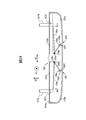
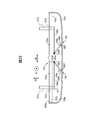
- 2A and 2B are schematic views for explaining the side guide 107.
- 2A and 2B are side views of the mounting table 103 removed from the lower housing 101 as viewed from the downstream side.
- first and second recesses 103b and c extending in the width direction A2 are formed on the mounting surface 103a of the mounting table 103, respectively. Further, first and second guide portions 103d and e are formed at the upstream and downstream end portions of the first and second recesses 103b and c. The first and second guide portions 103d and e are rails formed so as to extend in the width direction A2. On the other hand, the first and second protrusions 107c and d are formed at the upstream and downstream ends of the lower ends of the first and second side guides 107a and b in the height direction A3. Each side guide 107 slides in the width direction A2 on the mounting table 103 by moving the first and second protrusions 107c and d along the first and second guide portions 103d and e.
- the mounting table 103 has a first side guide sensor 108 and a second side guide sensor 109.
- the first side guide sensor 108 and the second side guide sensor 109 are provided inside the first and second recesses 103b and c, respectively, and below the first and second side guides 107a and b in the height direction A3.
- the first side guide sensor 108 includes an arm 108a, a support portion 108b, a shielding portion 108c, a torsion coil spring 108d, a stopper 108e, an optical sensor 108f, and the like.
- the second side guide sensor 109 includes an arm 109a, a support portion 109b, a shielding portion 109c, a torsion coil spring 109d, a stopper 109e, an optical sensor 109f, and the like. Since the structures and operations of the first side guide sensor 108 and the second side guide sensor 109 are the same, only the structure and operation of the first side guide sensor 108 will be described below as a representative.
- the arm 108a comes into contact with the first side guide 107a when the first side guide 107a is arranged inside (center side) of the predetermined position, and when the first side guide 107a is arranged outside the predetermined position, the arm 108a comes into contact with the first side guide 107a. It is provided so as not to come into contact with the first side guide 107a.
- the predetermined positions correspond to the arrangement position of the first side guide 107a arranged so as to abut the first size medium mounted on the mounting table 103 and the second size medium mounted on the mounting table 103. It is set between the arrangement position of the first side guide 107a arranged so as to be in contact with the first side guide 107a.
- the first size is the size of the short side of A5
- the second size is the size of the short side of B6.
- the support portion 108b is rotatably attached to the mounting base 103.
- the arm 108a and the shielding portion 108c are integrally supported by the supporting portion 108b so as to be integrally swingable (rotated) with the supporting portion 108b as a rotation axis.
- a torsion coil spring 108d is provided between the mounting base 103 and the arm 108a.
- the torsion coil spring 108d is provided around the support portion 108b so that a force is applied to the arm 108a in the direction of the arrow A11 (upward in the height direction A3).
- the mounting table 103 is provided with a stopper 108e for stopping the shielding portion 108c.
- the optical sensor 108f has a light emitter and a light receiver arranged so as to face each other.
- the light emitter irradiates light toward the receiver.
- the light receiver receives the light emitted by the light emitter and generates and outputs a first side guide signal which is an electric signal corresponding to the intensity of the received light.
- the shielding portion 108c is present between the light emitter and the light receiver, the light emitted by the light emitter is blocked by the shielding portion 108c. Therefore, the signal value of the first side guide signal changes according to the position of the shielding portion 108c, that is, according to the amount of movement of the arm 108a that moves together with the shielding portion 108c.
- the first side guide 107a does not come into contact with the arm 108a when it is arranged outside the predetermined position.
- the shielding portion 108c is pressed upward by the arm 108a pressed upward by the torsion coil spring 108d and comes into contact with the stopper 108e to stop.
- the shielding portion 108c does not exist between the light emitter and the receiver, and the signal value of the first side guide signal indicates a state in which the first side guide 107a exists outside the predetermined position.
- the first side guide 107a comes into contact with the arm 108a when it is arranged inside a predetermined position.
- the arm 108a is pushed down by the first side guide 107a in the direction opposite to the arrow A11, and the shielding portion 108c is moved downward by the arm 108a.
- the shielding portion 108c is arranged between the light emitter and the light receiver, and the signal value of the first side guide signal indicates a state in which the first side guide 107a exists inside the predetermined position.
- the optical sensor 109f generates and outputs a second side guide signal indicating whether the second side guide 107b exists inside the predetermined position or outside the predetermined position.
- the first side guide sensor 108 and the second side guide sensor 109 can appropriately detect the position of the side guide without using a special sensor having a complicated structure. Therefore, the medium transfer device 100 can appropriately detect the position of the side guide 107 while suppressing an increase in device cost or device weight.
- the first side guide sensor 108 and the second side guide sensor 109 may be provided inside the lower housing 101 instead of the mounting table 103.
- holes are provided in the surfaces of the mounting table 103 and the lower housing 101 facing each other, and the lower end of the side guide 107 in the height direction A3 is located on the downstream side of the medium transport direction A1.
- a protrusion extending toward the inside of the lower housing 101 through the hole is provided.
- the arms 108a and 109a come into contact with the protrusions of the side guides 107 when the side guides 107 are arranged inside the predetermined positions, and each side when the side guides 107 are arranged outside the predetermined positions. It is provided so as not to come into contact with the protrusion of the guide 107.
- the mounting table 103 provides electrical wiring between the optical sensors 108f and 109f and the processing circuit described later. It can be attached and detached from the lower housing 101 without consideration.
- the medium transfer device 100 may detect the position of the side guide 107 by using a push button instead of the optical sensors 108f and 109f.
- Each push button does not come into contact with the shielding portions 108c and 109c when the side guides 107 are arranged outside the predetermined positions, and the shielding portions 108c, with the side guides 107 arranged inside the predetermined positions. It is arranged so as to come into contact with the 109c and be pressed.
- Each push button generates and outputs a first and second side guide signal so that the signal value differs depending on whether or not the button is pressed.
- the medium transfer device 100 may detect the arrangement position of the side guide 107 by using a distance sensor instead of the first side guide sensor 108 and the second side guide sensor 109.
- a distance sensor instead of the first side guide sensor 108 and the second side guide sensor 109.
- a plurality of distance sensors are arranged side by side on the upper guide 110b on the upstream side with respect to the feeding roller 113 and the brake roller 114 and at intervals in the width direction A2.
- Each distance sensor is an infrared proximity sensor, and measures the distance to an object existing at an opposite position from the time difference from the irradiation of infrared rays to the reflection.
- Each distance sensor includes a light emitting unit and a light receiving unit. The light emitting unit irradiates light (infrared light) toward the mounting surface 103a of the mounting table 103.
- the light receiving unit receives the light that is irradiated by the corresponding light emitting unit and is reflected by the mounting surface 103a of the mounting table 103 or the side guide 107, and generates an electric signal corresponding to the received light.
- the generated signal indicates the time from when the light emitting unit irradiates light to when the light receiving unit receives light and the amount of light received by the light receiving unit. Therefore, the generated signal depends on whether the position where the light emitted by the light emitting unit is reflected is the mounting surface 103a or the side guide 107, that is, the side guide 107 is arranged at a position facing the light emitting unit. It changes depending on whether or not it is present. Therefore, the medium transfer device 100 can detect the arrangement position of the side guide 107 based on the electric signal generated by each distance sensor.
- FIG. 3 is a diagram for explaining a transport path inside the medium transport device 100.
- the transfer path inside the medium transfer device 100 includes a first medium sensor 111, a second medium sensor 112, a feed roller 113, a brake roller 114, a third medium sensor 115, a microphone 116, an ultrasonic transmitter 117a, and an ultrasonic receiver. It has 117b, a first transfer roller 118, a second transfer roller 119, a fourth medium sensor 120, a first image pickup device 121a, a second image pickup device 121b, a third transfer roller 122, a fourth transfer roller 123, and the like.
- the number of each roller is not limited to one, and the number of each roller may be plural.
- the first imaging device 121a and the second imaging device 121b may be collectively referred to as an imaging device 121.
- the upper surface of the lower housing 101 forms the lower guide 110a of the medium transport path
- the lower surface of the upper housing 102 forms the upper guide 110b of the medium transport path.
- the second medium sensor 112 is arranged on the downstream side of the first medium sensor 111 and on the upstream side of the feeding roller 113 and the brake roller 114.
- the second medium sensor 112 has a contact detection sensor and detects whether or not a medium is mounted on the mounting table 103.
- the second medium sensor 112 generates and outputs a second medium signal whose signal value changes depending on whether the medium is mounted on the mounting table 103 or not.
- the feeding roller 113 is provided in the lower housing 101, and feeds the media mounted on the mounting table 103 in order from the lower side.
- the brake roller 114 is provided on the upper housing 102 and is arranged so as to face the feeding roller 113.
- the third medium sensor 115 is arranged on the downstream side of the feed roller 113 and the brake roller 114 and on the upstream side of the first transfer roller 118 and the second transfer roller 119, and detects whether or not the medium exists at that position. ..
- the third medium sensor 115 is a reflection of a light emitter and a light receiver provided on one side of the medium transport path and a mirror or the like provided at a position facing the light emitter and the light receiver across the transport path. Including members. The light emitter irradiates light toward the transport path.
- the light receiver receives the light irradiated by the light emitter and reflected by the reflecting member, and generates and outputs a third medium signal which is an electric signal corresponding to the intensity of the received light.
- a medium is present at the position of the third medium sensor 115, the light emitted by the light emitter is blocked by the medium, so that the medium exists and does not exist at the position of the third medium sensor 115.
- the signal value of the three medium signals changes.
- the light emitter and the light receiver are provided at positions facing each other with the transport path interposed therebetween, and the reflective member may be omitted.
- the microphone 116 is provided in the vicinity of the medium transport path, receives (collects) the sound (audible sound) generated during the transport of the medium, and generates and outputs an analog sound signal corresponding to the received sound.
- the microphone 116 is fixedly arranged on the frame 116a inside the upper housing 102 on the downstream side of the feed roller 113 and the brake roller 114 and on the upstream side of the first transfer roller 118 and the second transfer roller 119.
- a hole 116b is provided at a position of the upper guide 110b facing the microphone 116 so that the microphone 116 can collect the sound generated while the medium is being conveyed more accurately.
- the ultrasonic transmitter 117a and the ultrasonic receiver 117b are arranged on the downstream side of the feeding roller 113 and the brake roller 114 and on the upstream side of the first transport roller 118 and the second transport roller 119.
- the ultrasonic transmitter 117a and the ultrasonic receiver 117b are arranged in the vicinity of the transport path of the medium so as to face each other with the transport path in between.
- the ultrasonic transmitter 117a can output ultrasonic waves.
- the ultrasonic receiver 117b receives the ultrasonic waves transmitted by the ultrasonic transmitter 117a and passed through the medium, and generates and outputs an ultrasonic signal which is an electric signal corresponding to the received ultrasonic waves.
- the ultrasonic transmitter 117a and the ultrasonic receiver 117b may be collectively referred to as an ultrasonic sensor 117.
- the first transfer roller 118 and the second transfer roller 119 are arranged on the downstream side of the feed roller 113 and the brake roller 114 and on the upstream side of the image pickup device 121.
- the fourth medium sensor 120 is arranged at a substantially central portion in the width direction A2 on the downstream side of the first transfer roller 118 and the second transfer roller 119 and on the upstream side of the image pickup apparatus 121, and whether or not the medium exists at that position. Is detected.
- the fourth medium sensor 120 is a reflection of a light emitter and a light receiver provided on one side of the medium transport path and a mirror or the like provided at a position facing the light emitter and the light receiver across the transport path. Including members. The light emitter irradiates light toward the transport path.
- the light receiver receives the light irradiated by the light emitter and reflected by the reflecting member, and generates and outputs a fourth medium signal which is an electric signal corresponding to the intensity of the received light.
- a medium is present at the position of the fourth medium sensor 120, the light emitted by the light emitter is blocked by the medium, so that the medium exists and does not exist at the position of the fourth medium sensor 120. 4
- the signal value of the medium signal changes.
- the light emitter and the light receiver are provided at positions facing each other with the transport path interposed therebetween, and the reflective member may be omitted.
- the first imaging device 121a is arranged on the downstream side of the first transfer roller 118 and the second transfer roller 119.
- the first image pickup device 121a has a line sensor by a CIS (Contact Image Sensor) of the same magnification optical system type having a CMOS (Complementary Metal Oxide Semiconductor) image pickup element arranged linearly in the main scanning direction. Further, the first image pickup apparatus 121a amplifies the light source that irradiates light toward the conveyed medium, the lens that forms an image on the image pickup element, and the electric signal output from the image pickup element, and is analog / digital (A). / D) It has an A / D converter to convert.
- the first image pickup apparatus 121a images a region facing the line sensor on the surface of the conveyed medium at regular intervals, sequentially generates a line image, and outputs the line image. That is, the number of pixels in the vertical direction (sub-scanning direction) of the line image is 1, and the number of pixels in the horizontal direction (main scanning direction) is a plurality.
- the second image pickup apparatus 121b is arranged on the downstream side of the first transfer roller 118 and the second transfer roller 119.
- the second image pickup apparatus 121b has a line sensor according to CIS of the same magnification optical system type having CMOS image pickup elements linearly arranged in the main scanning direction. Further, the second image pickup apparatus 121b amplifies the light source that irradiates light toward the conveyed medium, the lens that forms an image on the image pickup element, and the electric signal output from the image pickup element, and is analog / digital (A). / D) It has an A / D converter to convert.
- the second image pickup apparatus 121b images a region facing the line sensor on the back surface of the conveyed medium at regular intervals, sequentially generates a line image, and outputs the line image.
- the medium transfer device 100 may have only one of the first image pickup device 121a and the second image pickup device 121b and read only one side of the medium. Further, instead of the line sensor by the same magnification optical system type CIS including the image sensor by CMOS, the line sensor by the same magnification optical system type CIS including the image pickup element by CCD (Charge Coupled Device) may be used. Further, a reduction optical system type line sensor including a CMOS or CCD image sensor may be used.
- CCD Charge Coupled Device
- the medium mounted on the mounting table 103 is conveyed in the medium transport direction A1 between the lower guide 110a and the upper guide 110b by the feeding roller 113 rotating in the direction of the arrow A4 in FIG. ..
- the brake roller 114 rotates in the direction of arrow A5 when the medium is conveyed.
- the medium is fed between the first transfer roller 118 and the second transfer roller 119 while being guided by the lower guide 110a and the upper guide 110b.
- the medium is fed between the first imaging device 121a and the second imaging device 121b by rotating the first conveying roller 118 and the second conveying roller 119 in the directions of arrows A6 and A7, respectively.
- the medium read by the image pickup apparatus 121 is discharged onto the discharge table 104 by rotating the third transfer roller 122 and the fourth transfer roller 123 in the directions of the arrows A8 and A9, respectively.
- the feeding roller 113, the brake roller 114, the first transport roller 118, the second transport roller 119, the third transport roller 122, and the fourth transport roller 123 are examples of a transport mechanism that transports the medium.
- FIG. 4 is a schematic diagram for explaining the first medium sensor 111.
- FIG. 4 is a schematic view of the upstream side of the medium transfer device 100 as viewed from the side.
- the first medium sensor 111 is arranged on the upper guide 110b on the upstream side of the feeding roller 113 and the brake roller 114 and at the center of the upper housing 102 in the width direction A2.
- the first medium sensor 111 includes an arm 111a, a support portion 111b, a shielding portion 111c, a torsion coil spring 111d, a stopper 111e, an optical sensor 111f, and the like.
- the arm 111a is provided on the upper guide 110b and on the upstream side of the feeding roller 113 and the brake roller 114 so as to be in contact with the fed medium.
- the support portion 111b is rotatably attached to the upper housing 102.
- the arm 111a and the shielding portion 111c are supported by the supporting portion 111b so as to be integrally swingable (rotated) with the supporting portion 111b as a rotation axis.
- a torsion coil spring 111d is provided between the upper housing 102 and the arm 111a.
- the torsion coil spring 111d is provided around the support portion 111b so that a force is applied to the arm 111a in the direction of the arrow A12 (downward in the height direction A3).
- the stopper 111e is provided so as to stop the shielding portion 111c.
- the optical sensor 111f has a light emitter and a light receiver arranged so as to face each other.
- the light emitter irradiates light toward the receiver.
- the light receiver receives the light emitted by the light emitter, generates a first medium signal which is an electric signal corresponding to the intensity of the received light, and outputs the signal.
- the shield portion 111c is present between the light emitter and the light receiver, the light emitted by the light emitter is blocked by the shield portion 111c. Therefore, the signal value of the first medium signal changes according to the position of the shielding portion 111c, that is, according to the amount of movement of the arm 111a that moves together with the shielding portion 111c.
- the shielding portion 111c When the medium mounted on the mounting table 103 is not in contact with the arm 111a, the shielding portion 111c is pressed upward by the arm 111a pressed downward by the torsion coil spring 111d and comes into contact with the stopper 111e to stop. do. As a result, the shielding portion 111c is arranged between the light emitter and the light receiving receiver, and the signal value of the first medium signal indicates a state in which the arm 111a exists at the initial position shown in FIG. On the other hand, when the medium mounted on the mounting table 103 bends and comes into contact with the arm 111a, the arm 111a is pushed up in the direction opposite to the arrow A12 by the bent medium, and the shielding portion 111c moves downward by the arm 111a. As a result, the shielding portion 111c does not exist between the light emitter and the receiver, and the signal value of the first medium signal indicates a state in which the arm 111a does not exist at the initial position.
- FIG. 5 is a block diagram showing a schematic configuration of the medium transfer device 100.
- the medium transfer device 100 further includes a sound signal generation circuit 130, a motor 141, an interface device 142, a storage device 150, a processing circuit 160, and the like, in addition to the above-described configuration.
- the sound signal generation circuit 130 includes a microphone 116, a filter 131, an amplifier 132, an A / D converter 133, and the like.
- the filter 131 applies a bandpass filter that passes a signal in a predetermined frequency band to the analog sound signal output from the microphone 116, and outputs the bandpass filter to the amplifier 132.
- the amplifier 132 amplifies the signal output from the filter 131 and outputs it to the A / D converter 133.
- the A / D converter 133 samples the signal output from the amplifier 132 at predetermined intervals to generate a digitally converted digital sound signal, and outputs the digital sound signal to the processing circuit 160.
- the filter 131, the amplifier 132, and / or the A / D converter 133 may be included in the microphone 116, and the microphone 116 may output a digital sound signal.
- the motor 141 includes one or more motors, and the feed roller 113, the brake roller 114, and the first to fourth conveyor rollers 118, 119, 122, and 123 are rotated by a control signal from the processing circuit 160 to rotate the medium. To be transported.
- the interface device 142 has an interface circuit similar to a serial bus such as USB, and is electrically connected to an information processing device (not shown) to transmit and receive input images and various information. Further, instead of the interface device 142, a communication unit having an antenna for transmitting and receiving a wireless signal and a wireless communication interface device for transmitting and receiving a signal through a wireless communication line according to a predetermined communication protocol may be used.
- the predetermined communication protocol is, for example, a wireless LAN (Local Area Network).
- the storage device 150 includes a memory device such as a RAM (RandomAccessMemory) and a ROM (ReadOnlyMemory), a fixed disk device such as a hard disk, or a portable storage device such as a flexible disk and an optical disk. Further, the storage device 150 stores computer programs, databases, tables, etc. used for various processes of the medium transfer device 100.
- the computer program may be installed in the storage device 150 from a computer-readable portable recording medium using a known setup program or the like.
- the portable recording medium is, for example, a CD-ROM (compact disc read only memory), a DVD-ROM (digital versatile disc read only memory), or the like.
- the processing circuit 160 operates based on a program stored in the storage device 150 in advance.
- the processing circuit 160 is, for example, a CPU (Central Processing Unit).
- a DSP digital signal processor
- an LSI large scale integration
- an ASIC Application Specific Integrated Circuit
- an FPGA Field-Programmable Gate Array
- the processing circuit 160 includes an operating device 105, a display device 106, a first side guide sensor 108, a second side guide sensor 109, a first medium sensor 111, a second medium sensor 112, a third medium sensor 115, and an ultrasonic sensor 117. It is connected to a fourth medium sensor 120, an image pickup device 121, a sound signal generation circuit 130, a motor 141, an interface device 142, a storage device 150, and the like, and controls each of these parts.
- the processing circuit 160 performs drive control of the motor 141, image pickup control of the image pickup device 121, and the like, generates an input image, and transmits the input image to the information processing device via the interface device 142. Further, the processing circuit 160 determines whether or not a medium transport abnormality has occurred based on the output signal from each sensor, the line image from the image pickup device 121, and the like.
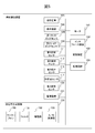
- FIG. 6 is a diagram showing a schematic configuration of a storage device 150 and a processing circuit 160.
- the storage device 150 stores a control program 151, a side guide detection program 152, a determination program 153, an image generation program 154, a size detection program 155, and the like.
- Each of these programs is a functional module implemented by software running on the processor.
- the processing circuit 160 reads each program stored in the storage device 150 and operates according to each read program. As a result, the processing circuit 160 functions as a control unit 161, a side guide detection unit 162, a determination unit 163, an image generation unit 164, and a size detection unit 165.
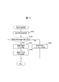
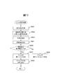
- FIG 7 and 8 are flowcharts showing an example of the operation of the medium reading process of the medium transport device 100.
- FIGS. 7 and 8 The operation flow described below is mainly executed by the processing circuit 160 in cooperation with each element of the medium transfer device 100 based on the program stored in the storage device 150 in advance.
- the flow of operations shown in FIGS. 7 and 8 is executed periodically. Further, before the flow of operations shown in FIGS. 7 and 8 is executed, a counter value for counting the number of conveyed media without causing a conveying abnormality is set as an initial value.
- control unit 161 waits until the user inputs an instruction to read the medium using the operation device 105 and receives an operation signal instructing to read the medium from the operation device 105 (step S101).
- control unit 161 acquires the second medium signal from the second medium sensor 112, and determines whether or not the medium is mounted on the mounting table 103 based on the acquired second medium signal (step). S102).
- control unit 161 When the medium is not mounted on the mounting table 103, the control unit 161 returns the process to step S101 and waits until a new operation signal is received from the operating device 105.
- the side guide detection unit 162 detects the placement position of the side guide 107 (step S103).
- the side guide detection unit 162 acquires the first side guide signal from the first side guide sensor 108, and based on the acquired first side guide signal, whether the first side guide 107a exists inside the predetermined position or at the predetermined position. Determine if it exists on the outer side. Further, the side guide detection unit 162 acquires the second side guide signal from the second side guide sensor 109, and based on the acquired second side guide signal, does the second side guide 107b exist inside the predetermined position? Determine if it exists outside the predetermined position.
- control unit 161 sets a transport mode for transporting the medium according to the arrangement position of the side guide 107 detected by the side guide detection unit 162 (step S104).
- the control unit 161 sets the transport mode to the normal mode for transporting a medium of a normal size of A5 size or larger.
- the control unit 161 sets the high-speed mode for transporting a small medium of B6 size or smaller.
- the parameters included in the transfer mode include the transfer speed of the medium, the transfer interval of the medium, the discharge rate of the medium, and / or the determination criteria of the transfer abnormality of the medium by the determination unit 163.
- a medium transfer abnormality is less likely to occur as compared with a case where a normal size medium is conveyed. Therefore, in the high-speed mode for transporting a small medium, each parameter is set so that the medium can be transported at a higher speed than in the normal mode for transporting a normal-sized medium.
- the transport speed of the medium is the rotation speed of the feed roller 113, the brake roller 114, and the first to fourth transport rollers 118, 119, 122, 123.
- the transport speed in the high-speed mode is set to a speed higher (faster) than the transport speed in the normal mode.
- the medium transfer interval is the time from the completion of the current medium transfer to the start of the next medium transfer.
- the transport interval in the high-speed mode is set to a time shorter than the transport interval in the normal mode.
- the discharge speed of the medium is the rotation speed of the third and fourth transport rollers 122 and 123 immediately before the medium is discharged. Small media are more likely to be scattered during ejection than normal size media.
- the transport speed in the high-speed mode is set to a speed lower (slower) than the transport speed in the normal mode so that the small medium is not scattered at the time of ejection.
- Media transport abnormalities include media jams, slips, double feeds and / or skews. Since the medium is conveyed at high speed in the high-speed mode, it is desirable that the medium transfer device 100 stops the transfer of the medium earlier so that the medium is not damaged when a medium transfer abnormality occurs in the high-speed mode. Therefore, the criterion for determining the transport abnormality of the medium in the high-speed mode is set so that it is easier to determine that the transport abnormality of the medium has occurred than the criterion for the transport abnormality of the medium in the normal mode.
- a criterion for determining the jam of the medium in the normal mode it is set that the state in which the arm 111a does not exist at the initial position continues for the first jam time or longer.
- a criterion for determining the jam of the medium in the high-speed mode it is set that the state in which the arm 111a does not exist at the initial position continues for the second jam time or more, which is shorter than the first jam time.
- the first jam time and the second jam time are preset based on the time during which the medium continues to bend when the medium jam occurs in an experiment in which various types of media are conveyed.
- the medium transport device 100 prevents the small medium from being damaged by setting the criterion for determining the jam of the medium in the high-speed mode, which is set when the small medium having weak stiffness, is set so that it is easy to determine that the jam has occurred. Can be suppressed.
- a criterion for determining the slip of the medium in the normal mode it is set that the tip of the medium does not pass through the position of the third medium sensor 115 from the start of feeding the medium to the elapse of the first slip time. ..
- the tip of the medium passes through the position of the third medium sensor 115 from the start of feeding the medium to the elapse of the second slip time shorter than the first slip time. Not set to not.
- the first slip time and the second slip time are experiments in which various types of media are conveyed, and the time elapsed from the start of feeding the medium until the tip of the medium passes through the position of the third medium sensor 115.
- the medium transport device 100 erroneously determines that slip has occurred by setting the criterion for determining the slip of the medium in the normal mode, which is set when transporting a large-sized medium, so that it is difficult to determine that slip has occurred. Can be suppressed.
- the same criteria are set for the high-speed mode and the normal mode as the criteria for determining the double feed of the medium. For example, it is set that the signal value of the ultrasonic signal is less than the first double feed threshold value as a criterion for determining the double feed of the medium.
- different criteria may be set for the high-speed mode and the normal mode. In that case, the above-mentioned determination criteria are set as the determination criteria for double feeding of the medium in the normal mode.
- a criterion for determining the double feed of the medium in the high-speed mode it is set that the signal value of the ultrasonic signal is larger than the first double feed threshold and less than the second double feed threshold.
- the first double feed threshold value and the second double feed threshold value are the signal value of the ultrasonic signal when one sheet of paper is being conveyed and the signal value of the ultrasonic signal when double feed of the paper is occurring. Set to a value between.
- the criteria for determining the skew of the medium are set for the high-speed mode and the normal mode. For example, as a criterion for determining the skew of the medium, when the first skew time elapses after any end of the tip of the medium reaches the imaging position, the central portion of the tip of the medium is the position of the fourth medium sensor 120. It is set that has not been reached.
- different criteria may be set for the high-speed mode and the normal mode. In that case, the above-mentioned determination criteria are set as the determination criteria for skewing the medium in the normal mode.
- the central portion of the tip of the medium when the second skew time shorter than the first skew time elapses after any end of the tip of the medium reaches the imaging position. Is set not to reach the position of the fourth medium sensor 120.
- a criterion for determining the skew of the medium it may be set that the difference in time when each of the plurality of portions at the tip of the medium reaches the imaging position is equal to or greater than each skew time.
- a plurality of optical sensors are arranged side by side at intervals in the width direction A2 on the transport path of the medium transport device 100, and the difference in time when the tip of the medium reaches the position of each optical sensor as a criterion for determining the skew of the medium. May be set to be greater than or equal to each skew time.
- the control unit 161 sets the transport mode according to the arrangement position of the side guide 107 detected by the side guide detection unit 162. That is, the control unit 161 sets the transport speed of the medium to be conveyed first among the media mounted on the mounting table 103, the transfer interval of the medium, or the discharge rate of the medium according to the arrangement position of the side guide 107.
- the transport mechanism is controlled so as to be used, or the criteria for determining the transport abnormality of the medium are set. Since the side guides 107 are usually set to regulate the width direction of the medium, the size of the conveyed medium is likely to be the same as the distance between the two side guides 107.
- the control unit 161 can transport the medium in a transport mode suitable for the medium to be transported. As a result, the control unit 161 can satisfactorily convey the medium.
- control unit 161 may set at least one of the parameters of the transport mode, the transport speed of the medium, the transport interval of the medium, the discharge speed of the medium, and the determination criteria of the transport abnormality of the medium. Further, the control unit 161 may notify the user by displaying the set operation mode or the transport speed on the display device 106. As a result, the user can recognize the currently set operation mode, and the medium transfer device 100 can improve the convenience of the user.
- the control unit 161 drives the motor 141 to rotate the feeding roller 113, the brake roller 114, and the first to fourth transport rollers 118, 119, 122, and 123 to transport the medium (step S105). ..
- the control unit 161 rotates the feed roller 113 and the first to fourth transport rollers 118, 119, 122, and 123 in the directions of arrows A4, A6, A7, A8, and A9 (media feed direction or medium transport direction), respectively.
- the motor 141 is driven so as to be driven.
- the control unit 161 drives the motor 141 so as to rotate the brake roller 114 in the direction of the arrow A5 (the direction opposite to the medium feeding direction).
- the control unit 161 controls the motor 141 so that the medium is conveyed according to the set transfer mode.
- the control unit 161 sets the jam flag, slip flag, double feed flag, and skew flag to OFF (step S106).
- the jam flag is set to ON when the determination unit 163 determines that a medium jam has occurred in the jam determination process described later.
- the slip flag is set to ON when it is determined by the determination unit 163 that slip of the medium has occurred in the slip determination process described later.
- the double feed flag is set to ON when it is determined by the determination unit 163 that double feed of the medium has occurred in the double feed determination process described later.
- the skew flag is set to ON when it is determined by the determination unit 163 that skew of the medium has occurred in the skew determination process described later.
- the determination unit 163 determines whether or not any of the jam flag, slip flag, double feed flag, and skew flag is ON (step S107).
- the determination unit 163 determines that a medium transfer abnormality has occurred (step S108).
- control unit 161 stops the motor 141 and stops the feeding and transporting of the medium (step S109).
- the control unit 161 can prevent the medium from being damaged by stopping the feeding and transporting of the medium when an abnormality in the transport of the medium has occurred. Further, the control unit 161 displays on the display device 106 that an abnormality has occurred, or transmits the information to the information processing device via the interface device 142 to notify the user of the warning.
- control unit 161 points the feeding rollers 113 and the first to fourth conveying rollers 118, 119, 122, and 123 at arrows A4, A6, A7, A8, and A9 (medium feeding direction or medium conveying direction), respectively.
- the motor 141 is driven so as to rotate in the opposite direction.
- control unit 161 drives the motor 141 so as to rotate the brake roller 114 in the direction of the arrow A5 (the direction opposite to the medium feeding direction).
- the control unit 161 reversely feeds the medium and temporarily returns it to the mounting table 103 (step S110).
- control unit 161 resets the counter value (step S111).
- control unit 161 resets the transport mode to the mode set in step S104 (step S112). Since the transport mode may have been changed in the process described later, the control unit 161 resets the transport mode to the mode initially set.
- control unit 161 redrives the motor 141 and rerotates the feeding rollers 113 and the first to fourth conveying rollers 118, 119, 122, 123 in the medium feeding direction or the medium conveying direction, and the medium. Is re-delivered and re-transported (step S113). Next, the control unit 161 returns the process to step S106.
- step S107 when all the flags of the jam flag, the slip flag, the double feed flag, and the skew flag are OFF, the control unit 161 determines whether or not the entire medium has passed the imaging position of the imaging device 121. Determine (step S114).
- the control unit 161 periodically acquires a fourth medium signal from the fourth medium sensor 120, and determines whether or not a medium exists at the position of the fourth medium sensor 120 based on the acquired fourth medium signal. ..
- the control unit 161 determines the position of the fourth medium sensor 120 at the rear end of the medium. Judge that it has passed.
- the control unit 161 determines that the entire medium has passed the imaging position when a predetermined time has elapsed since the rear end of the medium passed the position of the fourth medium sensor 120. When the control unit 161 acquires a predetermined number of line images from the image pickup apparatus 121, the control unit 161 may determine that the entire conveyed medium has passed the image pickup position. If the entire medium has not yet passed the imaging position, the control unit 161 returns the process to step S107.
- the determination unit 163 determines that the medium has not been conveyed abnormally and the medium has been normally conveyed (step S115). In this way, the determination unit 163 determines whether or not a medium transfer abnormality has occurred.
- control unit 161 increments (+1) the counter value (step S116).
- the image generation unit 164 acquires each line image generated during medium transport from the image pickup apparatus 121, synthesizes all the acquired line images, generates an input image in which the medium is imaged, and interfaces with the image generation unit 164. It is transmitted to the information processing device via the device 142 (step S117).
- control unit 161 temporarily stops the motor 141 and temporarily stops feeding and transporting to the medium (step S118).
- control unit 161 determines whether or not the medium remains on the mounting table 103 based on the second medium signal acquired from the second medium sensor 112 (step S119). If no medium remains on the mounting table 103, the control unit 161 ends a series of steps.
- the size detection unit 165 detects the size of the medium included in the input image generated by the image generation unit 164 (step S120).
- the size detection unit 165 performs edge extraction processing on the input image, and the pixel whose difference in gradation value (luminance value or color value) from the peripheral pixel is equal to or larger than a predetermined value, or the gradation value is a threshold value. Pixels having the above and the gradation value of the peripheral pixels is less than the threshold value are extracted as edge pixels.
- the size detection unit 165 detects a plurality of straight lines from the extracted edge pixels by using the least squares method or the Hough transform.
- the size detection unit 165 detects the rectangle having the largest size among the rectangles composed of four straight lines corresponding to the left side, the right side, the upper side, and the lower side of the document as a medium.
- the size detection unit 165 calculates the size of the detected medium.
- the size detection unit 165 may detect the size of the medium from the input image by using other known image processing techniques such as pattern matching.
- the size detection unit 165 may detect the size of the conveyed medium based on the medium signal output from the medium sensor. In that case, a plurality of fourth medium sensors 120 are provided so as to be arranged side by side at intervals in the width direction A2, and the size detection unit 165 periodically outputs a fourth medium signal from each of the fourth medium sensors 120. get.
- the size detection unit 165 detects the size of the conveyed medium in the width direction A2 based on the number of fourth medium signals whose signal values indicate the presence of the medium. Further, the size detection unit 165 determines that the signal value of the fourth medium signal indicating that the medium exists is based on the period during which the signal value indicates the existence of the medium, and the medium transport direction of the conveyed medium. Detect the size of A1.
- control unit 161 changes the transport mode according to the size of the medium detected by the size detection unit 165 (step S121).
- the control unit 161 changes the transport mode to the normal mode.
- the control unit 161 changes the transport mode to the high-speed mode.
- control unit 161 controls the transfer mechanism so as to change the transfer speed of the medium to be conveyed thereafter, the transfer interval of the medium, or the discharge rate of the medium according to the size of the detected medium, or the control unit 161 of the medium. Change the criteria for transport abnormality.
- the medium may be conveyed without the side guide 107 being set so as to regulate the width direction of the medium. In that case, the size of the medium actually transported does not match the distance between the two side guides 107.
- the control unit 161 can increase the possibility of transporting the medium in a transport mode suitable for the medium to be transported thereafter. As a result, the control unit 161 can satisfactorily convey the medium.
- control unit 161 may change at least one of the parameters of the transport mode, that is, the transport speed of the medium, the transport interval of the medium, the discharge speed of the medium, and the determination criteria of the transport abnormality of the medium. Further, when the operation mode is changed, the control unit 161 may notify the user that the operation mode has been changed by displaying the changed operation mode or the transport speed on the display device 106. As a result, the user can recognize that the operation mode has been changed or the changed operation mode, and the medium transfer device 100 can improve the convenience of the user.
- control unit 161 determines whether or not the counter value is equal to or greater than a predetermined number (step S122). If the counter value is less than a predetermined number, the control unit 161 does not execute any particular process, and returns the process to step S105.
- control unit 161 transports the medium to be conveyed thereafter so as to increase the transfer speed (higher speed) or reduce the transfer interval of the medium to be conveyed thereafter.
- the mode is changed (step S123).
- control unit 161 when the control unit 161 does not cause a transfer abnormality of the medium when a predetermined number of media are conveyed, the control unit 161 increases the transfer speed of the medium to be conveyed thereafter, or the control unit 161 increases the transfer speed of the medium to be conveyed thereafter.
- the transport mechanism is controlled so as to reduce the transport interval.
- the control unit 161 can reduce the time required for transporting each medium within a range in which the transport abnormality of the medium does not occur, and can reduce the total time of the medium reading process.
- control unit 161 may change at least one of the transport speed and the transport interval of the medium. Further, when the transfer speed or the transfer interval of the medium is changed, the control unit 161 displays to the user that the transfer speed or the transfer interval has been changed, and displays the changed transfer speed or the transfer interval on the display device 106. You may notify. As a result, the user can recognize that the transport speed or the transport interval has been changed, or the changed transport speed or the transport interval, and the medium transport device 100 improves the convenience of the user. Can be done.
- control unit 161 changes the determination criterion of the medium transfer abnormality by the determination unit 163 so that it is easy to determine that the medium transfer abnormality has occurred (step S124), and returns the process to step S105.
- the control unit 161 sets the criterion for jamming the medium so that the state in which the arm 111a does not exist at the initial position continues for a jam time shorter than the currently set jam time.
- the control unit 161 determines that the slip of the medium is determined by the third medium sensor 115 at the tip of the medium from the start of feeding the medium until the slip time shorter than the currently set slip time elapses. Set not to pass the position of.
- the control unit 161 does not change the judgment criteria for double feeding of the medium and / or the judgment criteria for skew.
- the control unit 161 may also change the determination criteria for double feed and / or the determination criteria for skew. In that case, the control unit 161 sets the determination criterion of the double feed so that the signal value of the ultrasonic signal is smaller than the double feed threshold value which is larger than the currently set double feed threshold value. Further, the control unit 161 determines the skew determination criteria when the skew time shorter than the currently set skew time elapses after any end of the tip of the medium reaches the imaging position. It is set that the central portion does not reach the position of the fourth medium sensor 120.
- control unit 161 controls the transfer mechanism so as to increase the transfer speed of the medium or reduce the transfer interval of the medium, the control unit 161 can easily determine that the transfer abnormality of the medium has occurred. Change the criteria for abnormalities. As a result, the control unit 161 stops the transfer of the medium earlier even if the transfer abnormality of the medium occurs as a result of reducing the time required for the transfer process of the medium too much, and the medium is damaged. Occurrence can be prevented.
- control unit 161 may set any of three or more modes as the transport mode, instead of setting one of the two modes of the normal mode and the high-speed mode. Even in that case, each mode is set according to the arrangement position of the side guide 107 and / or the size of the medium.
- the medium transfer device 100 is provided with a plurality of first side guide sensors 108 and a plurality of second side guide sensors 109, and the side guide detection unit 162 has any of the position ranges of three or more side guides 107. Determine if it is included in.
- the control unit 161 sets the transport mode to a mode corresponding to the determined position range.
- the size detection unit 165 determines which of the three or more size ranges the size of the medium is included in.
- the control unit 161 changes the transport mode to a mode corresponding to the determined size range.
- step S104 the control unit 161 may set the transport mode based on other information instead of the arrangement position of the side guide 107.
- the control unit 161 receives a mode setting from a user from an information processing device (not shown) using the operation device 105 or via the interface device 142, and stores the mode setting in the storage device 150.
- the control unit 161 sets the mode stored in the storage device 150 as the transport mode.
- the control unit 161 stores the transfer result (the number or rate of occurrences of the medium transfer abnormality) in the medium reading process in the past predetermined period in the storage device 150, and stores it in the storage device 150 in step S104.
- the transport mode may be set based on the transport result.
- the control unit 161 may set a predetermined fixed mode as the transport mode in step S104. Further, the processes of steps S120 and S121 are omitted, and the control unit 161 does not have to change the transport mode.
- steps S109 to S110 and S112 to S113 are omitted, and when a medium transport abnormality occurs, the control unit 161 notifies only the user of a warning without stopping the feed and transport of the medium. You may. Further, when the processing of steps S110 to S113 is omitted and the feeding and transporting of the medium are stopped, the control unit 161 may end a series of steps without refeeding the medium.
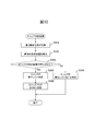
- FIG. 9 is a flowchart showing an example of the operation of the jam determination process of the medium transfer device 100.
- the operation flow described below is mainly executed by the processing circuit 160 in cooperation with each element of the medium transfer device 100 based on the program stored in the storage device 150 in advance.
- the flow of operations shown in FIG. 9 is periodically executed during medium transfer.
- the determination unit 163 acquires the first medium signal from the first medium sensor 111 (step S201). Next, the determination unit 163 detects the position of the arm 111a based on the first medium signal (step S202). Next, the determination unit 163 determines whether or not the currently set medium jam determination criterion is satisfied (step S203). If the determination criteria for medium jam is not satisfied, the determination unit 163 determines that no medium jam has occurred (step S204), and ends a series of steps. On the other hand, when the criterion for jamming the medium is satisfied, the determination unit 163 determines that the conveyed medium is bent and the medium is jammed (step S205). Next, the determination unit 163 sets the jam flag to ON (step S206) and ends a series of steps.
- the determination unit 163 determines whether or not a medium jam has occurred as a medium transfer abnormality based on the output signal from the first medium sensor 111.
- FIG. 10 is a flowchart showing an example of the operation of the slip determination process of the medium transfer device 100.
- the operation flow described below is mainly executed by the processing circuit 160 in cooperation with each element of the medium transfer device 100 based on the program stored in the storage device 150 in advance.
- the flow of operations shown in FIG. 10 is periodically executed during medium transfer.
- the determination unit 163 acquires the third medium signal from the third medium sensor 115 (step S301). Next, the determination unit 163 detects the position of the tip of the medium based on the third medium signal (step S302). When the signal value of the third medium signal acquired periodically changes from a value indicating that the medium does not exist to a value indicating that the medium exists, the determination unit 163 indicates that the tip of the medium is the third medium sensor. It is determined that the position of 115 has been reached. Next, the determination unit 163 determines whether or not the currently set criterion for slip of the medium is satisfied (step S303).
- the determination unit 163 determines that the slip of the medium has not occurred (step S304), and ends a series of steps.
- the determination unit 163 determines that the feed roller 113 cannot sufficiently grasp the medium and the slip of the medium has occurred (step S305). ..
- the determination unit 163 sets the slip flag to ON (step S306) and ends a series of steps.
- control unit 161 may drive the motor 141 so as to rotate the feeding roller 113 by a predetermined amount.
- the predetermined amount is set so that the tip of the medium can be fed from the position of the feeding roller 113 to the positions of the first and second transport rollers 118 and 119.
- the control unit 161 drives the motor 141 so as to rotate the feeding roller 113 by a predetermined amount, then acquires the third medium signal from the third medium sensor 115, and based on the third medium signal, the control unit 161 of the medium. It is determined whether or not the tip has reached the position of the third medium sensor 115. When the tip of the medium has not reached the position of the third medium sensor 115, the control unit 161 redrives the motor 141 so as to rotate the feeding roller 113 by a predetermined amount.
- a criterion for determining the slip of the medium in the normal mode it is set that the tip of the medium does not pass through the position of the third medium sensor 115 even if the control unit 161 redrives the motor 141 for the number of first slips. ..
- the tip of the medium in the high-speed mode the tip of the medium does not pass through the position of the third medium sensor 115 even if the control unit 161 redrives the motor 141 for the second slip count smaller than the first slip count. Is set.
- the determination unit 163 determines whether or not the media slips as a medium transport abnormality based on the output signal from the third medium sensor 115.
- FIG. 11 is a flowchart showing an example of the operation of the double feed determination process of the medium transfer device 100.
- the operation flow described below is mainly executed by the processing circuit 160 in cooperation with each element of the medium transfer device 100 based on the program stored in the storage device 150 in advance.
- the flow of operations shown in FIG. 11 is periodically executed during medium transfer.
- the determination unit 163 acquires an ultrasonic signal from the ultrasonic sensor 117 (step S401). Next, the determination unit 163 determines whether or not the currently set determination criteria for double feeding of the medium is satisfied (step S402). If the determination criteria for double feeding of the medium is not satisfied, the determination unit 163 determines that double feeding of the medium has not occurred (step S403), and ends a series of steps. On the other hand, when the determination criteria for double feeding of the medium is satisfied, the determination unit 163 determines that double feeding of the medium has occurred (step S404). Next, the determination unit 163 sets the double feed flag to ON (step S405) and ends a series of steps.
- the determination unit 163 determines whether or not double feeding of the medium has occurred as a transfer abnormality of the medium based on the output signal from the ultrasonic sensor 117.
- FIG. 12 is a flowchart showing an example of the operation of the skew determination process of the medium transfer device 100.
- the operation flow described below is mainly executed by the processing circuit 160 in cooperation with each element of the medium transfer device 100 based on the program stored in the storage device 150 in advance.
- the flow of operations shown in FIG. 12 is periodically executed during medium transfer.
- the determination unit 163 acquires the fourth medium signal from the fourth medium sensor 120 and acquires the line image from the image pickup apparatus 121 (step S501).
- the determination unit 163 acquires a line image from the image pickup device 121 each time the image pickup device 121 generates a line image.
- the determination unit 163 detects the position of the tip of the medium based on the fourth medium signal and the line image (step S502). In the determination unit 163, when the signal value of the fourth medium signal acquired periodically changes from a value indicating that the medium does not exist to a value indicating that the medium exists, the central portion of the tip of the medium becomes the first. 4 It is determined that the position of the medium sensor 120 has been reached. Further, the determination unit 163 calculates the average value of the gradation values of the pixels in each end region within a predetermined range from both ends of the line image for each of the latest line image and the line image acquired immediately before.
- the determination unit 163 determines that the absolute value of the difference between the average value calculated from each end region of the latest line image and the average value calculated from each end region of the immediately preceding line image is equal to or greater than the gradation threshold value. It is determined that each end of the tip of the medium has reached the imaging position. On the other hand, when the absolute value of the difference is less than the gradation threshold value, the determination unit 163 determines that each end of the tip of the medium has not yet reached the imaging position.
- the gradation value is a luminance value or a color value (R value, G value or B value).
- the gradation threshold value is set to, for example, a difference in gradation value (for example, 20) that allows a person to visually discriminate a difference in brightness or color on an image.
- the determination unit 163 determines whether or not the currently set media skew determination criterion is satisfied (step S503). If the criteria for determining the skew of the medium are not satisfied, the determination unit 163 determines that the skew of the medium has not occurred (step S504), and ends a series of steps. On the other hand, when the determination criterion of the skew of the medium is satisfied, the determination unit 163 determines that the skew of the medium has occurred (step S505). Next, the determination unit 163 sets the skew flag to ON (step S506) and ends a series of steps.
- the determination unit 163 determines whether or not the skew of the medium has occurred as a transfer abnormality of the medium based on the output image from the image pickup apparatus 121 and / or the output signal from the fourth medium sensor 120. ..
- the determination unit 163 may determine whether or not at least one of jam, slip, double feed, and skew of the medium has occurred as a medium transfer abnormality.
- the medium transport device 100 when the medium transport device 100 does not cause a medium transport abnormality when a predetermined number of media are transported, that is, when a plurality of media are stably transported, the following Increase the transport speed of the transport medium or reduce the transport interval of the medium. As a result, the medium transport device 100 can further reduce the time required for transporting the medium while suppressing the occurrence of abnormal transport of the medium.
- the medium transfer device 100 suppresses the occurrence of abnormal medium transfer regardless of the state of the medium, even for a plurality of media having different sizes, a medium having damage such as tearing or chipping, or a medium having dirt. At the same time, it has become possible to reduce the time required for transporting the medium. The user does not need to change the transport mode according to the medium to be transported, and the medium transport device 100 can reduce the load on the user and improve the convenience of the user.
- FIG. 13 is a flowchart showing another example of the operation of the jam determination process of the medium transfer device 100. The flowchart shown in FIG. 13 is executed in place of or in addition to the flowchart shown in FIG.
- step S104 of FIG. 7 and step S121 of FIG. 8 it is determined in step S104 of FIG. 7 and step S121 of FIG. 8 that a medium jam has occurred using the first parameter group as a criterion for determining the medium jam in the normal mode. Is set to be done. On the other hand, as a criterion for determining the jam of the medium in the high-speed mode, it is set that it is determined that the jam of the medium has occurred using the second parameter group.
- the first parameter group and the second parameter group include a first threshold value, a second threshold value, an addition point and a subtraction point.
- the first threshold value is a threshold value for comparison with the signal value of the sound signal.
- the second threshold value is a threshold value for comparison with an evaluation value calculated based on the number of times that the signal value of the sound signal is equal to or greater than the first threshold value.
- the addition point is a point to be added to the evaluation value when the signal value of the sound signal is equal to or higher than the first threshold value.
- the subtraction point is a point to be subtracted from the evaluation value when the signal value of the sound signal is less than the first threshold value.
- the second parameter group is set so that it is easier to determine that a medium jam has occurred than the first parameter group.
- the first threshold value, the second threshold value and the subtraction point included in the second parameter group are set to values smaller than the first threshold value, the second threshold value and the subtraction point included in the first parameter group.
- the addition points included in the second parameter group are set to a value larger than the addition points included in the first parameter group.
- control unit 161 sets the first threshold value, the second threshold value, and the subtraction point to values smaller than the currently set first threshold value, the second threshold value, and the subtraction point, and adds points. Is set to a value larger than the currently set addition point.
- the determination unit 163 acquires a sound signal from the sound signal generation circuit 130 (step S601).
- FIG. 14A is a graph showing an example of a sound signal.
- the graph 1400 shown in FIG. 14A represents a sound signal output from the sound signal generation circuit 130.
- the horizontal axis of the graph 1400 shows time, and the vertical axis shows signal values.
- the determination unit 163 generates a signal obtained by taking an absolute value of the sound signal output from the sound signal generation circuit 130 (step S602).
- FIG. 14B is a graph showing an example of a signal in which the absolute value of the sound signal is taken.
- Graph 1410 shown in FIG. 14B represents a signal obtained by taking the absolute value of the sound signal of graph 1400.
- the horizontal axis of the graph 1410 indicates time, and the vertical axis indicates the absolute value of the signal value.
- the determination unit 163 generates an outer shape signal obtained by extracting the outer shape of the signal from which the absolute value of the sound signal is taken (step S603).
- the determination unit 163 extracts the envelope as an external signal.
- FIG. 14C is a graph showing an example of an external signal.
- Graph 1420 shown in FIG. 14C represents the envelope 1421 of the signal taking the absolute value of the sound signal of graph 1410.
- the horizontal axis of the graph 1420 indicates time, and the vertical axis indicates the absolute value of the signal value.
- the determination unit 163 calculates an evaluation value based on the external signal (step S604).
- the determination unit 163 calculates the evaluation value of the external signal so as to increase it when the signal value is equal to or more than the first threshold value and decrease it when the signal value is less than the first threshold value.
- the determination unit 163 determines whether or not the value of the envelope 1421 is equal to or greater than the first threshold value at predetermined time intervals (for example, sampling intervals for analog-to-digital conversion).
- the determination unit 163 adds addition points to the evaluation value when the value of the envelope 1421 is equal to or greater than the first threshold value, and subtracts subtraction points from the evaluation value when the value is less than the first threshold value.
- FIG. 14D is a graph showing an example of evaluation values.
- Graph 1430 shown in FIG. 14D represents an evaluation value calculated for the envelope 1421 of graph 1420.
- the horizontal axis of the graph 1420 indicates time, and the vertical axis indicates counter value.
- the determination unit 163 determines whether or not the evaluation value is equal to or greater than the second threshold value (step S605). When the evaluation value is less than the second threshold value, the determination unit 163 determines that no jam has occurred in the medium (step S606), and ends a series of steps. On the other hand, when the evaluation value is equal to or higher than the second threshold value, the determination unit 163 determines that the medium jam has occurred (step S607). Next, the determination unit 163 sets the jam flag to ON (step S608) and ends a series of steps.
- the envelope 1421 is equal to or more than the first threshold value at time T1 and is not less than the first threshold value thereafter. Therefore, as shown in FIG. 14D, the evaluation value increases from the time T1 and becomes equal to or higher than the second threshold value at the time T2, and the determination unit 163 determines that the medium transfer abnormality has occurred.
- the determination unit 163 determines whether or not a medium jam has occurred as a medium transfer abnormality based on the sound signal from the sound signal generation circuit 130.
- the determination unit 163 calculates the evaluation value by adding the addition points or subtracting the subtraction points based on the comparison between the sound signal and the first threshold value, and based on the comparison between the evaluation value and the second threshold value, the medium. It is determined whether or not a transport abnormality has occurred.
- the determination unit 163 may obtain a signal obtained by peak-holding a signal obtained by taking the absolute value of the sound signal at predetermined intervals, instead of obtaining the envelope as the external signal. Further, the determination unit 163 may obtain a signal obtained by applying a known smoothing filter, averaging filter, or low-pass filter to the signal obtained by taking the absolute value of the sound signal as the external signal.
- the medium transfer device 100 reduces the time required for medium transfer while suppressing the occurrence of medium transfer abnormality. It has become possible to reduce it.
- FIG. 15 is a diagram showing a schematic configuration of a processing circuit 260 in a medium transfer device according to another embodiment.
- the processing circuit 260 is used in place of the processing circuit 160 of the medium transfer device 100, and executes the medium reading process, the jam determination process, the slip determination process, the double feed determination process, and the skew determination process in place of the processing circuit 160.
- the processing circuit 260 includes a control circuit 261, a side guide detection circuit 262, a determination circuit 263, an image generation circuit 264, a size detection circuit 265, and the like. Each of these parts may be composed of independent integrated circuits, microprocessors, firmware, and the like.
- the control circuit 261 is an example of a control unit, and has the same function as the control unit 161.
- the control circuit 261 reads from the storage device 150 a jam flag, a slip flag, a double feed flag, a skew flag, a side guide arrangement position, a medium size, a determination result of a medium transport abnormality, and the like.
- the control circuit 261 sets or changes the operation mode according to each read information and stores it in the storage device 150. Further, the control circuit 261 receives an operation signal from the operation device 105, a second medium signal from the second medium sensor 112, and a third medium signal from the third medium sensor 115, and the storage device 150 receives a medium transfer abnormality. Read the judgment result.
- the control circuit 261 outputs a control signal to the motor 141 so as to control the feeding and transporting of the medium according to each received signal and the read information.
- the side guide detection circuit 262 is an example of the side guide detection unit, and has the same function as the side guide detection unit 162.
- the side guide detection circuit 262 receives the first side guide signal from the first side guide sensor 108 and the second side guide signal from the second side guide sensor 109, detects the arrangement position of the side guide, and stores the detection result. Store in device 150.
- the determination circuit 263 is an example of the determination unit and has the same function as the determination unit 163.
- the determination circuit 263 receives the first medium signal from the first medium sensor 111, or receives the sound signal from the sound signal generation circuit 130. Further, the determination circuit 263 receives a third medium signal from the third medium sensor 115, a fourth medium signal from the fourth medium sensor 120, a line image from the image pickup device 121, and an ultrasonic signal from the ultrasonic sensor 117. ..
- the determination circuit 263 determines whether or not a medium transport abnormality has occurred based on each received signal or image, and stores the determination result in the storage device 150.
- the image generation circuit 264 is an example of the image generation unit, and has the same function as the image generation unit 164.
- the image generation circuit 264 receives a line image from the image pickup device 121, generates an input image, stores the input image in the storage device 150, and transmits the line image to the information processing device via the interface device 142.
- the size detection circuit 265 is an example of the size detection unit, and has the same function as the size detection unit 165.
- the size detection circuit 265 reads the input image from the storage device 150, detects the size of the medium, and stores it in the storage device 150.
- the medium transport device can further reduce the time required for transporting the medium while suppressing the occurrence of the medium transport abnormality.
Landscapes
- Engineering & Computer Science (AREA)
- Mechanical Engineering (AREA)
- Controlling Sheets Or Webs (AREA)
- Paper Feeding For Electrophotography (AREA)
- Facsimiles In General (AREA)
- Facsimile Scanning Arrangements (AREA)
Abstract
Description
Claims (7)
- 媒体を搬送する搬送機構と、
媒体の搬送異常が発生したか否かを判定する判定部と、
所定数の媒体を搬送させたときに媒体の搬送異常が発生しなかった場合、以降に搬送する媒体の搬送速度を増大させ、又は、以降に搬送する媒体の搬送間隔を低減させるように前記搬送機構を制御する制御部と、
を有することを特徴とする媒体搬送装置。 - 媒体が撮像された入力画像を生成する画像生成部と、
前記入力画像内に含まれる媒体のサイズを検出するサイズ検出部と、をさらに有し、
前記制御部は、前記検出されたサイズに応じて、以降に搬送する媒体の搬送速度、媒体の搬送間隔又は媒体の排出速度を変更するように前記搬送機構を制御し、又は、前記判定部による媒体の搬送異常の判定基準を変更する、請求項1に記載の媒体搬送装置。 - 載置台と、
媒体の幅方向を規制するサイドガイドと、
前記サイドガイドの配置位置を検出するサイドガイド検出部と、をさらに有し、
前記制御部は、前記検出された配置位置に応じて、前記載置台に載置された媒体の内の最初に搬送する媒体の搬送速度、媒体の搬送間隔又は媒体の排出速度を設定するように前記搬送機構を制御し、又は、前記判定部による媒体の搬送異常の判定基準を設定する、請求項1または2に記載の媒体搬送装置。 - 前記制御部は、媒体の搬送速度を増大又は媒体の搬送間隔を低減させるように前記搬送機構を制御した場合、媒体の搬送異常が発生したと判定しやすくなるように、前記判定部による媒体の搬送異常の判定基準を変更する、請求項1~3の何れか一項に記載の媒体搬送装置。
- 前記判定部は、媒体の搬送異常として、媒体のジャム、スリップ、重送又はスキューが発生したか否かを判定する、請求項1~4の何れか一項に記載の媒体搬送装置。
- 媒体を搬送する搬送機構を有する媒体搬送装置の制御方法であって、
媒体の搬送異常が発生したか否かを判定し、
所定数の媒体を搬送させたときに媒体の搬送異常が発生しなかった場合、以降に搬送する媒体の搬送速度を増大させ、又は、以降に搬送する媒体の搬送間隔を低減させるように前記搬送機構を制御する、
ことを特徴とする制御方法。 - 媒体を搬送する搬送機構を有する媒体搬送装置の制御プログラムであって、
媒体の搬送異常が発生したか否かを判定し、
所定数の媒体を搬送させたときに媒体の搬送異常が発生しなかった場合、以降に搬送する媒体の搬送速度を増大させ、又は、以降に搬送する媒体の搬送間隔を低減させるように前記搬送機構を制御する、
ことを前記媒体搬送装置に実行させることを特徴とする制御プログラム。
Priority Applications (4)
| Application Number | Priority Date | Filing Date | Title |
|---|---|---|---|
| JP2022507934A JP7259132B2 (ja) | 2020-03-18 | 2020-03-18 | 媒体搬送装置、制御方法及び制御プログラム |
| PCT/JP2020/012114 WO2021186643A1 (ja) | 2020-03-18 | 2020-03-18 | 媒体搬送装置、制御方法及び制御プログラム |
| US17/755,918 US12304764B2 (en) | 2020-03-18 | 2020-03-18 | Medium transport device, control method, and control program |
| JP2023061411A JP7607069B2 (ja) | 2020-03-18 | 2023-04-05 | 媒体搬送装置、制御方法及び制御プログラム |
Applications Claiming Priority (1)
| Application Number | Priority Date | Filing Date | Title |
|---|---|---|---|
| PCT/JP2020/012114 WO2021186643A1 (ja) | 2020-03-18 | 2020-03-18 | 媒体搬送装置、制御方法及び制御プログラム |
Publications (1)
| Publication Number | Publication Date |
|---|---|
| WO2021186643A1 true WO2021186643A1 (ja) | 2021-09-23 |
Family
ID=77771745
Family Applications (1)
| Application Number | Title | Priority Date | Filing Date |
|---|---|---|---|
| PCT/JP2020/012114 Ceased WO2021186643A1 (ja) | 2020-03-18 | 2020-03-18 | 媒体搬送装置、制御方法及び制御プログラム |
Country Status (3)
| Country | Link |
|---|---|
| US (1) | US12304764B2 (ja) |
| JP (2) | JP7259132B2 (ja) |
| WO (1) | WO2021186643A1 (ja) |
Cited By (1)
| Publication number | Priority date | Publication date | Assignee | Title |
|---|---|---|---|---|
| JP2023083336A (ja) * | 2020-03-18 | 2023-06-15 | 株式会社Pfu | 媒体搬送装置、制御方法及び制御プログラム |
Families Citing this family (1)
| Publication number | Priority date | Publication date | Assignee | Title |
|---|---|---|---|---|
| JP7275373B2 (ja) * | 2020-03-02 | 2023-05-17 | 株式会社Pfu | 媒体搬送装置、制御方法及び制御プログラム |
Citations (2)
| Publication number | Priority date | Publication date | Assignee | Title |
|---|---|---|---|---|
| JP2016086285A (ja) * | 2014-10-24 | 2016-05-19 | 理想科学工業株式会社 | 画像読取装置 |
| JP2019198007A (ja) * | 2018-05-10 | 2019-11-14 | キヤノン株式会社 | 画像読取装置およびその制御方法、並びにプログラム |
Family Cites Families (14)
| Publication number | Priority date | Publication date | Assignee | Title |
|---|---|---|---|---|
| JP3337720B2 (ja) * | 1991-10-15 | 2002-10-21 | キヤノン株式会社 | シート搬送装置 |
| JPH1111689A (ja) | 1997-06-30 | 1999-01-19 | Canon Inc | シート積載装置及び画像形成装置 |
| JPH1160053A (ja) | 1997-08-25 | 1999-03-02 | Ricoh Co Ltd | 原稿給紙装置 |
| JP2000264445A (ja) | 1999-03-18 | 2000-09-26 | Fuji Photo Film Co Ltd | 給紙装置の用紙サイズ検出装置、画像読取装置およびその制御方法 |
| JP2001013740A (ja) | 1999-06-25 | 2001-01-19 | Ricoh Co Ltd | 自動原稿搬送装置 |
| JP3954919B2 (ja) | 2002-07-26 | 2007-08-08 | 株式会社リコー | 画像形成装置 |
| JP2005324455A (ja) * | 2004-05-14 | 2005-11-24 | Brother Ind Ltd | シート材搬送装置、およびシート材搬送方法 |
| JP5341493B2 (ja) | 2008-12-17 | 2013-11-13 | キヤノン株式会社 | シート搬送装置 |
| US9027925B2 (en) * | 2013-04-30 | 2015-05-12 | Lexmark International, Inc. | Methods for feeding media sheets having increased throughput |
| JP6387851B2 (ja) * | 2015-02-13 | 2018-09-12 | ブラザー工業株式会社 | シート搬送装置およびシート搬送方法 |
| JP2019151439A (ja) | 2018-03-01 | 2019-09-12 | キヤノン株式会社 | 画像形成装置 |
| US11203499B2 (en) * | 2018-10-11 | 2021-12-21 | Kyocera Document Solutions Inc. | System and method for monitoring health of a sheet-conveyance system |
| CN112055125A (zh) * | 2019-06-05 | 2020-12-08 | 佳能株式会社 | 片材传送装置、原稿读取装置和成像设备 |
| US12304764B2 (en) | 2020-03-18 | 2025-05-20 | Pfu Limited | Medium transport device, control method, and control program |
-
2020
- 2020-03-18 US US17/755,918 patent/US12304764B2/en active Active
- 2020-03-18 WO PCT/JP2020/012114 patent/WO2021186643A1/ja not_active Ceased
- 2020-03-18 JP JP2022507934A patent/JP7259132B2/ja active Active
-
2023
- 2023-04-05 JP JP2023061411A patent/JP7607069B2/ja active Active
Patent Citations (2)
| Publication number | Priority date | Publication date | Assignee | Title |
|---|---|---|---|---|
| JP2016086285A (ja) * | 2014-10-24 | 2016-05-19 | 理想科学工業株式会社 | 画像読取装置 |
| JP2019198007A (ja) * | 2018-05-10 | 2019-11-14 | キヤノン株式会社 | 画像読取装置およびその制御方法、並びにプログラム |
Cited By (2)
| Publication number | Priority date | Publication date | Assignee | Title |
|---|---|---|---|---|
| JP2023083336A (ja) * | 2020-03-18 | 2023-06-15 | 株式会社Pfu | 媒体搬送装置、制御方法及び制御プログラム |
| JP7607069B2 (ja) | 2020-03-18 | 2024-12-26 | 株式会社Pfu | 媒体搬送装置、制御方法及び制御プログラム |
Also Published As
| Publication number | Publication date |
|---|---|
| JP7259132B2 (ja) | 2023-04-17 |
| JP7607069B2 (ja) | 2024-12-26 |
| US20220380167A1 (en) | 2022-12-01 |
| JP2023083336A (ja) | 2023-06-15 |
| JPWO2021186643A1 (ja) | 2021-09-23 |
| US12304764B2 (en) | 2025-05-20 |
Similar Documents
| Publication | Publication Date | Title |
|---|---|---|
| JP7633366B2 (ja) | 重送検出装置、制御方法及び制御プログラム | |
| JP7414574B2 (ja) | 媒体搬送装置、制御方法及び制御プログラム | |
| JP7607069B2 (ja) | 媒体搬送装置、制御方法及び制御プログラム | |
| JP2025061303A (ja) | 媒体搬送装置、制御方法及び制御プログラム | |
| JP7774691B2 (ja) | 媒体搬送装置、制御方法及び制御プログラム | |
| JP7467694B2 (ja) | 画像読取装置、制御方法及び制御プログラム | |
| JP7579701B2 (ja) | 媒体搬送装置、制御方法及び制御プログラム | |
| JP7133492B2 (ja) | 重送検出装置、制御方法及び制御プログラム | |
| JP7565712B2 (ja) | 媒体搬送装置、制御方法及び制御プログラム | |
| JP6884119B2 (ja) | 用紙搬送装置、制御方法及び制御プログラム | |
| JP7191198B2 (ja) | 重送検出装置、制御方法及び制御プログラム | |
| JP7728427B2 (ja) | 媒体搬送装置、制御方法及び制御プログラム | |
| JP7201470B2 (ja) | 媒体搬送装置、制御方法及び制御プログラム | |
| JP7653797B2 (ja) | 媒体搬送装置、制御方法及び制御プログラム | |
| JP7337727B2 (ja) | 媒体搬送装置、制御方法及び制御プログラム | |
| US20250206554A1 (en) | Medium conveying apparatus, medium conveying method, and computer-readable non-transitory medium | |
| JP7698736B2 (ja) | 媒体搬送装置、制御方法及び制御プログラム | |
| US20240025680A1 (en) | Medium conveying apparatus to detect predetermined medium based on lift of medium | |
| JP2024159138A (ja) | 媒体搬送装置、画像処理システム、媒体搬送方法及び制御プログラム | |
| WO2022034659A1 (ja) | 媒体搬送装置、制御方法及び制御プログラム | |
| JP2020155966A (ja) | 媒体読取装置、制御方法及び制御プログラム |
Legal Events
| Date | Code | Title | Description |
|---|---|---|---|
| 121 | Ep: the epo has been informed by wipo that ep was designated in this application |
Ref document number: 20925429 Country of ref document: EP Kind code of ref document: A1 |
|
| ENP | Entry into the national phase |
Ref document number: 2022507934 Country of ref document: JP Kind code of ref document: A |
|
| NENP | Non-entry into the national phase |
Ref country code: DE |
|
| 122 | Ep: pct application non-entry in european phase |
Ref document number: 20925429 Country of ref document: EP Kind code of ref document: A1 |
|
| WWG | Wipo information: grant in national office |
Ref document number: 17755918 Country of ref document: US |