WO2021186562A1 - 基板処理装置、半導体装置の製造方法及びプログラム - Google Patents
基板処理装置、半導体装置の製造方法及びプログラム Download PDFInfo
- Publication number
- WO2021186562A1 WO2021186562A1 PCT/JP2020/011754 JP2020011754W WO2021186562A1 WO 2021186562 A1 WO2021186562 A1 WO 2021186562A1 JP 2020011754 W JP2020011754 W JP 2020011754W WO 2021186562 A1 WO2021186562 A1 WO 2021186562A1
- Authority
- WO
- WIPO (PCT)
- Prior art keywords
- processing
- substrate
- gas
- inert gas
- supply port
- Prior art date
- Legal status (The legal status is an assumption and is not a legal conclusion. Google has not performed a legal analysis and makes no representation as to the accuracy of the status listed.)
- Ceased
Links
Images


Classifications
-
- H—ELECTRICITY
- H01—ELECTRIC ELEMENTS
- H01L—SEMICONDUCTOR DEVICES NOT COVERED BY CLASS H10
- H01L21/00—Processes or apparatus adapted for the manufacture or treatment of semiconductor or solid state devices or of parts thereof
- H01L21/02—Manufacture or treatment of semiconductor devices or of parts thereof
- H01L21/04—Manufacture or treatment of semiconductor devices or of parts thereof the devices having potential barriers, e.g. a PN junction, depletion layer or carrier concentration layer
- H01L21/18—Manufacture or treatment of semiconductor devices or of parts thereof the devices having potential barriers, e.g. a PN junction, depletion layer or carrier concentration layer the devices having semiconductor bodies comprising elements of Group IV of the Periodic Table or AIIIBV compounds with or without impurities, e.g. doping materials
- H01L21/30—Treatment of semiconductor bodies using processes or apparatus not provided for in groups H01L21/20 - H01L21/26
- H01L21/324—Thermal treatment for modifying the properties of semiconductor bodies, e.g. annealing, sintering
Definitions
- This disclosure relates to a substrate processing apparatus, a manufacturing method and a program of a semiconductor apparatus.
- a substrate processing apparatus having a processing chamber capable of annealing a substrate is disclosed (see Patent Document 1).
- the substrate may be hydrogen-annealed under various pressures in a hydrogen gas atmosphere. At that time, there are cases where only hydrogen is used, or a gas in which helium, nitrogen, argon and hydrogen are mixed is used.
- ignition and combustion occur when the conditions of combustible gas, combustion supporting gas, and ignition source are met.
- the treatment using high-concentration hydrogen gas is performed under a slight decompression or an atmospheric pressure, when the gas in the treatment chamber is ignited for some reason, the gas in the treatment chamber expands and the treatment chamber is pressurized. Under reduced pressure, it can be easily dealt with so that the pressurization limit value is not exceeded during expansion, but for processing under slightly reduced pressure or atmospheric pressure, it is sufficient to make the entire processing chamber with high pressure resistance. Safety measures are essential.
- An object of the present disclosure is to facilitate treatment of a substrate under a slight decompression or an atmospheric pressure with a high concentration of hydrogen gas.
- the substrate processing apparatus includes a substrate holding table that can be raised and lowered inside a processing container, a processing space between an upper surface of the substrate holding table in an raised state and a surface facing the upper surface, and a raised state.
- An inert gas is applied to the space between the shielding wall surrounding the outer periphery of the substrate holding table, the processing gas supply port for supplying the processing gas containing hydrogen gas to the processing space, and the shielding wall and the inner wall of the processing container. It has an inert gas supply port to be supplied, and a gas mixing portion in which the treated gas discharged from the treatment space is mixed with the inert gas inside the treatment container.
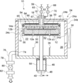
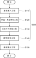
- FIG. 1 It is sectional drawing which shows the state which the substrate holding table was lowered in the substrate processing apparatus which concerns on 1st Embodiment. It is sectional drawing which shows the state which the substrate holding table is raised in the substrate processing apparatus which concerns on 1st Embodiment. It is an enlarged cross-sectional view which shows the flow of the processing gas and the inert gas at the time of hydrogen annealing processing in the substrate processing apparatus which concerns on 1st Embodiment. It is sectional drawing which shows the other example of the inert gas supply port in the substrate processing apparatus which concerns on 1st Embodiment. It is a schematic block diagram of the controller of a substrate processing apparatus. It is a flow chart of a substrate processing process. FIG.
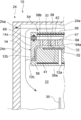
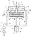
- FIG. 5 is an enlarged cross-sectional view showing another example of a shower head in the substrate processing apparatus according to the first embodiment. It is sectional drawing which shows the state which the substrate holding table was lowered in the substrate processing apparatus which concerns on 2nd Embodiment. It is sectional drawing which shows the state which the substrate holding table is raised in the substrate processing apparatus which concerns on 2nd Embodiment. It is an enlarged cross-sectional view which shows the flow of the processing gas and the inert gas at the time of hydrogen annealing processing in the substrate processing apparatus which concerns on 2nd Embodiment.
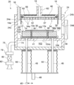
- the substrate processing device 10 includes a substrate holding table 12, a shielding wall 14, a processing gas supply port 16, an inert gas supply port 18, and a gas mixing unit 22.
- the substrate holding table 12 is, for example, a disk-shaped susceptor provided inside the processing container 24, that is, in the processing chamber, and can be raised and lowered in the processing container 24.
- the processing container 24 is configured as, for example, a flat closed container having a circular cross section.
- the processing container 24 is made of a metal material such as aluminum (Al) or stainless steel (SUS) or quartz.
- a transport space 26 for transporting the substrate 30 is formed in the processing container 24.
- a processing space 32 for processing a silicon wafer or the like as the substrate 30 is formed in the processing container 24 when the substrate holding table 12 is raised.
- the processing container 24 is composed of an upper container 24a and a lower container 24b.
- a substrate carry-in / outlet 24d adjacent to the gate valve 34 is provided on the side surface of the lower container 24b.
- the substrate 30 moves between the transport space 26 in the lower container 24b and the vacuum transport chamber (not shown) via the substrate carry-in outlet 24d.
- a plurality of lift pins 36 are provided at the bottom of the lower container 24b.
- a mounting surface 38a on which the board 30 is mounted is provided, for example, in a concave shape.
- an outer upper surface 38b on which the substrate 30 is not mounted is provided on the radial outer side of the mounting surface 38a.
- the mounting surface 38a is provided on the upper surface 38 of the substrate holding table 12, for example, in a concave shape. That is, the upper surface 38 of the substrate holding table 12 has a mounting surface 38a and an outer upper surface 38b.
- the outer upper surface 38b is configured to be substantially flush with the upper surface of the substrate 30.
- the outer upper surface 38b makes it possible to bring the amount of processing gas supplied to the outer peripheral side of the substrate 30 closer to the amount of processing gas supplied to the center side of the substrate 30.
- An overhanging portion 12c is provided below the outer circumference 12b of the substrate holding table 12. The overhanging portion 12c is a portion that projects radially outward from the outer peripheral portion 12b in a flange shape.
- the substrate holding table 12 may be provided with a first heater 41 as a heating unit.
- the first heater 41 By providing the first heater 41, the substrate 30 can be heated and the quality of the film formed on the substrate 30 can be improved.
- the first heater 41 is connected to the temperature control unit 40 and is configured so that the temperature can be controlled.
- the temperature control unit 40 is configured to be able to transmit and receive temperature data to and from the controller 44 (FIG. 9) described later via a signal line.
- the board holding base 12 is provided with through holes 12a through which the lift pin 36 penetrates at positions corresponding to the lift pin 36.
- the substrate holding table 12 may be provided with a film thickness monitor (not shown) for measuring the film thickness of the film formed on the substrate 30.
- the film thickness monitor is connected to the film thickness meter via a signal line. Then, the film thickness value (film thickness data) generated by the film thickness meter is configured to be transmitted and received to the controller 44 (FIG. 9) described later via the signal line.
- the board holding base 12 is supported by, for example, one shaft 46.
- the shaft 46 penetrates the bottom of the processing container 24 and is further connected to the elevating mechanism 48 outside the processing container 24.
- the elevating mechanism 48 By operating the elevating mechanism 48 to elevate the shaft 46 and the substrate holding base 12, the substrate 30 mounted on the mounting surface 38a can be elevated.
- the lower end of the shaft 46 is covered with a bellows 50, and the inside of the processing container 24 is kept airtight.
- the elevating mechanism 48 is configured to be able to transmit the height data of the board holding base 12 to the controller 44 described later.
- the substrate holding table 12 is lowered so that the mounting surface 38a is at the position of the substrate loading / unloading port 24d (that is, the transport position), and when the substrate 30 is processed, the substrate holding table 12 is lowered. As shown in FIG. 2, the substrate 30 rises to the processing position (that is, the processing position) in the processing container 24.
- the upper end portion of the lift pin 36 protrudes from the mounting surface 38a and pushes up the board 30 from below, and the board 30 is pushed up to the upper surface 38 of the board holding table 12, specifically. Is supported in a state of being lifted to a position higher than the outer upper surface 38b.
- the lift pin 36 is buried from the mounting surface 38a, and the mounting surface 38a supports the substrate 30 from below. Since the lift pin 36 comes into direct contact with the substrate 30, it is desirable that the lift pin 36 is made of a material such as quartz or alumina.
- the lift pin 36 may be provided with an elevating mechanism so that the substrate holding base 12 and the lift pin 36 move relative to each other.
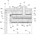
- the shielding wall 14 is a processing space 32 between the upper surface 38 of the substrate holding table 12 in the raised state and the facing surface 52 with respect to the upper surface 38, and the outer periphery of the board holding table 12 in the raised state. It is provided as a portion surrounding 12b. Since the substrate 30 is actually mounted on the mounting surface 38a for processing, the processing space 32 is provided between the upper surface of the substrate 30 mounted on the mounting surface 38a and the facing surface 52 facing the upper surface. It is formed.
- the shielding wall 14 is integrally provided with, for example, the shower head 54 described later. Specifically, the shielding wall 14 is provided as a portion that extends downward in a cylindrical shape from the radial outer end portion of the shower head 54. In the state where the substrate holding table 12 is raised to the processing position, the shower head 54 including the shielding wall 14 does not come into contact with the substrate 30 and the substrate holding table 12, and the upper surface of the substrate 30 mounted on the mounting surface 38a and the upper surface of the substrate 30.
- the processing space 32 is formed between the facing surface 52 facing the upper surface.
- a processing gas flow path 56 is formed between the inner peripheral surface of the shielding wall 14 and the outer peripheral surface 12b of the substrate holding table 12, and between the lower end of the shielding wall 14 and the overhanging portion 12c of the substrate holding table 12. It has become so.
- the treatment gas flow path 56 is a flow path that guides the treatment gas containing hydrogen gas supplied to the treatment space 32 to a position where it exits the treatment space 32 and joins with the inert gas.
- the processing gas flow path 56 communicates between the processing space 32 and the gas mixing unit 22 described later, and constitutes a flow path through which the processing gas flows from the processing space 32 toward the gas mixing unit 22.
- the lower end position of the board holding table 12 is raised so as to be located at a height lower than the lower end of the shielding wall 14.
- the substrate is held by the total length of the width (thickness) of the overhanging portion 12c in the height direction and the width of the processing gas flow path 56 between the lower end of the shielding wall 14 and the overhanging portion 12c.
- the substrate holding table 12 is raised so that the lower end position of the table 12 is lower than the lower end of the shielding wall 14.
- the processing gas supply port 16 is a portion for supplying the processing gas containing hydrogen gas to the processing space 32.
- An MFC (Mass Flow Controller) 58 as a flow rate control device for the processing gas and a processing gas valve 60 as an on-off valve are connected to the processing gas supply port 16.
- the processing gas supply unit (processing gas supply system) is configured by the MFC 58, the processing gas valve 60, and the processing gas supply port 16.
- the concentration of hydrogen gas in the processing gas in the processing space 32 is 4% or more.
- the concentration of hydrogen gas in the processing gas according to this embodiment may be 100%.
- the flow rate of the inert gas supplied from the inert gas supply port 18 into the processing container 24 is 24 times or more that of the processing gas.
- the concentration of hydrogen gas in the gas mixing unit 22 can be reduced to less than 4%.
- the concentration of hydrogen gas in the gas mixing unit 22 By setting the concentration of hydrogen gas in the gas mixing unit 22 to less than 4%, it is possible to prevent sudden combustion due to ignition of hydrogen gas even when hydrogen gas and oxygen are mixed. .. In other words, by adopting the apparatus configuration according to the present embodiment, even when the concentration of hydrogen gas in the processing gas supplied to the processing space 32 is 4% or more, rapid combustion due to ignition is prevented. can do.
- the concentration of hydrogen gas in the processing gas supplied to the processing space 32 is 100%, there is a higher possibility that a mixture of hydrogen gas and oxygen will occur due to leakage of hydrogen gas or the like. Adoption of the device configuration is more preferable.
- the concentration of hydrogen gas in the mixing unit 22 is less than 4%, it is desirable that the concentration is as low as possible, but since there is a substantial limit to the flow rate of the inert gas required for dilution, 0.1%. It is appropriate to set the above range.
- the processing gas supply port 16 is formed on a tubular support shaft (shower head) 62 extending in the vertical direction.
- the support shaft (shower head) 62 penetrates the ceiling surface 24e of the processing container 24.
- the processing gas supply port 16 is composed of a single or a plurality of processing gas ejection holes 54a provided on the facing surface 52.
- the processing gas supply port 16 is composed of a shower head 54.
- the shower head 54 is provided in the processing container 24, and is configured so that the processing gas supplied from the processing gas supply port 16 can be dispersed and supplied to the processing space 32.
- the shower head 54 can also be rephrased as a "gas dispersion unit".
- a plurality of processing gas ejection holes 54a are provided on the surface 52 facing the upper surface 38 of the substrate holding table 12.
- the processing gas ejection holes 54a are arranged on the entire facing surface 52. Assuming that the portion provided with the processing gas ejection hole 54a is called the perforated plate 64, the lower surface of the perforated plate 64 is the facing surface 52.
- the shower head 54 is surrounded by a perforated plate 64, a lid 66 located above the perforated plate 64, a spacer 65 sandwiched between the perforated plate 64 and the lid 66, and the perforated plate 64, the lid 66, and the spacer 65. It has a buffer space 67.
- the lid 66 is provided with a second heater 42 for heating the processing gas.
- the shower head 54 is arranged in the processing container 24 away from the ceiling surface 24e of the processing container 24. Specifically, the processing gas introduced from the processing gas supply port 16 is supplied to the buffer space 67 in the shower head 54, and the processing space 32 is supplied from the buffer space 67 through the plurality of processing gas ejection holes 54a of the perforated plate 64. It is widely distributed to the market.
- the perforated plate 64 in the shower head 54 is made of, for example, a material such as quartz, alumina, stainless steel, or aluminum.
- a gas guide (not shown) that forms a flow of the supplied gas may be provided in the buffer space 67.
- the gas guide is provided, for example, on the lower surface of the lid 66, and its shape is a conical shape whose diameter increases toward the lower side of the substrate 30 centering on the portion where the processing gas supply port 16 opens into the buffer space 67.
- the inert gas supply port 18 is a portion that supplies the inert gas to the space between the shielding wall 14 and the inner wall 24c of the processing container 24.
- As the inert gas for example, nitrogen gas is used.
- the MFC 68 as a flow control device for the inert gas and the valve 70 for the inert gas are connected to the inert gas supply port 18.
- the MFC 68, the inert gas valve 70, and the inert gas supply port 18 constitute an inert gas supply unit (inert gas supply system).
- the flow rate of the inert gas supplied from the inert gas supply port 18 into the processing container 24 is adjusted so that the concentration of the hydrogen gas in the gas mixing unit 22 is, for example, less than 4%.
- the inert gas supply port 18 is provided at least on the central side of the ceiling surface 24e of the processing container 24 with respect to directly above the outer edge of the shower head 54.
- the inert gas supply port 18 is concentric with the support shaft (shower head) 62 on the outside of the support shaft (shower head) 62 of the shower head 54 at the center of the ceiling surface 24e of the processing container 24. It is provided in. In other words, the support shaft (shower head) 62 of the shower head 54 is inserted into the inert gas supply port 18.
- the inert gas supply port 18 is provided at the position of the upper end 14a of the shielding wall 14 or at a position higher than the upper end of the shielding wall 14 on the outside of the shielding wall 14 and inside the inner wall 24c in the processing container 24.
- the inert gas is supplied from the inert gas supply port 18 between the upper surface of the shower head 54 and the ceiling surface 24e of the processing container 24, and reaches the space between the shielding wall 14 and the inner wall 24c of the processing container 24. It is configured as follows.
- the arrangement of the inert gas supply port 18 is not limited to the examples shown in FIGS. 1 to 3.
- a plurality of the inert gas supply ports 18 may be provided in the circumferential direction along the outer edge of the shower head 54 on the ceiling surface 24e of the processing container 24, for example. This circumferential direction is the circumferential direction of the shower head 54.
- the plurality of inert gas supply ports 18 may be provided evenly in the circumferential direction, or may be provided unevenly in the circumferential direction.
- the gas mixing unit 22 is a portion where the processing gas leaving the processing space 32 is mixed with the inert gas.
- the processing gas containing hydrogen gas is diluted by mixing with the inert gas.
- the inert gas supplied from the inert gas supply port 18 flows from the upper side to the lower side in the space between the shielding wall 14 and the inner wall 24c of the processing container 24.
- the processing gas exits the processing space 32 and passes through the processing gas flow path 56 between the shielding wall 14 and the substrate holding table 12, it merges with the inert gas and is mixed with the inert gas. That is, in the inside of the processing container 24, the space below the confluence of the processing gas and the inert gas is the gas mixing unit 22.
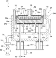
- the substrate processing device 10 further has an exhaust unit (exhaust system).
- This exhaust portion is provided in, for example, the lower container 24b.
- the inner wall 24c of the lower container 24b is provided with an exhaust port 74 for exhausting the atmosphere of the processing container 24.
- the upstream end of the exhaust pipe 76 is connected to the exhaust port 74 from the outside of the processing container 24.
- the exhaust pipe 76 is provided with an APC (Auto Pressure Controller) 78 as a pressure regulator (pressure regulator), a vent valve 80 as an on-off valve, and a vacuum pump 82 as a vacuum exhaust device in order from the upstream side.
- the exhaust portion is composed of an exhaust port 74, an exhaust pipe 76, an APC 78, and a vent valve 80.
- the exhaust unit may further include a vacuum pump 82.
- the pressure in the processing space 32 is adjusted to be atmospheric pressure or a slight decompression with respect to the atmospheric pressure.
- the range of slight decompression is, for example, "220 Torr or more and less than atmospheric pressure". This is a range in which the pressure in the processing space 32 may exceed the atmospheric pressure when the volume of hydrogen gas having a combustion upper limit concentration (75%) is rapidly expanded due to combustion. That is, in such a pressure range, the apparatus configuration according to the present embodiment is useful for ensuring safety.
- the range of slight decompression may be, for example, "300 Torr or more and less than atmospheric pressure”. This is a range in which a practical effect can be obtained by hydrogen annealing treatment on a metal film or metal wiring formed on a substrate. If necessary, the pressure in the processing space 32 may be higher than the atmospheric pressure.
- the substrate processing apparatus 10 has a controller 44 as a control unit.
- the controller 44 has a gate valve 34, an elevating mechanism 48, an APC 78, a vacuum pump 82, a first heater 41, a second heater 42, a processing gas valve 60, an inert gas valve 70, and a vent valve 80 through a signal line (not shown). Is configured to control each. Further, although omitted in FIG. 5, the controller 44 is configured to control the MFC 58, the processing gas valve 60, the MFC 68, and the inert gas valve 70 shown in FIG. 1, respectively.
- the controller 44 which is a control unit (control means), is a computer provided with a CPU (Central Processing Unit) 84a, a RAM (Random Access Memory) 84b, a storage device 84c, and an I / O port 84d. It is configured.
- the RAM 84b, the storage device 84c, and the I / O port 84d are configured so that data can be exchanged with the CPU 84a via the internal bus 84e.
- An input / output device 86 configured as, for example, a touch panel or a display is connected to the controller 44.
- the storage device 84c is composed of, for example, a flash memory, an HDD (Hard Disk Drive), or the like.
- a control program for controlling the operation of the substrate processing apparatus a program recipe in which the procedures and conditions for substrate processing described later are described, and the like are readablely stored.
- the process recipes are combined so that the controller 44 can execute each procedure in the substrate processing step described later and obtain a predetermined result, and functions as a program.
- this program recipe, control program, etc. are collectively referred to as a program.
- the term program is used in the present specification, it may include only the program recipe alone, the control program alone, or both.
- the RAM 84b is configured as a memory area (work area) in which programs, data, and the like read by the CPU 84a are temporarily held.
- the I / O port 84d includes the above-mentioned gate valve 34, elevating mechanism 48, APC78, vacuum pump 82, first heater 41, second heater 42, processing gas valve 60, inert gas valve 70, vent valve 80, and the like. It is connected to the MFC 58, the processing gas valve 60, the MFC 68, the inert gas valve 70, and the like.
- the CPU 84a is configured to read and execute a control program from the storage device 84c and read a process recipe from the storage device 84c in response to an input of an operation command from the input / output device 86 or the like. Then, the CPU 84a opens and closes the gate valve 34, raises and lowers the elevating mechanism 48, and adjusts the opening degree of the APC 78 through the I / O port 84d and a signal line (not shown) so as to follow the contents of the read process recipe. , Starting and stopping the vacuum pump 82, adjusting the amount of power supplied to the first heater 41 and the second heater 42 (temperature adjusting operation), processing gas valve 60, inert gas valve 70, vent valve 80, processing gas. It is configured to control the opening / closing operation of the valve 60, the flow rate adjusting operation of various gases of the MFC 58 and the MFC 68, and the like.
- the controller 44 is stored in an external storage device (for example, magnetic tape, magnetic disk such as flexible disk or hard disk, optical disk such as CD or DVD, magneto-optical disk such as MO, semiconductor memory such as USB memory or memory card) 88. It can be configured by installing the above program on the computer.
- the storage device 84c and the external storage device 88 are configured as a computer-readable recording medium. Hereinafter, these are collectively referred to simply as a recording medium. In the present specification, when the term recording medium is used, the storage device 84c alone may be included, the external storage device 88 alone may be included, or both of them may be included.
- the means for supplying the program to the computer is not limited to the case of supplying the program via the external storage device 88.
- a communication means such as a network 90 (Internet or a dedicated line) may be used to supply the program without going through the external storage device 88.
- FIG. 6 is a flow chart showing a substrate processing process according to the present embodiment.
- the metal film and metal wiring formed on the substrate are annealed (hydrogen annealing treatment) in an atmosphere containing hydrogen gas.
- the method for manufacturing the semiconductor device includes a substrate loading step S110 for loading the substrate 30 into the processing container 24 of the substrate processing apparatus 10, and a processing step S200 (S120 to S140) for performing a hydrogen annealing treatment on the substrate 30.
- This substrate processing step is carried out by the above-mentioned substrate processing apparatus 10 as one step of a manufacturing process of a semiconductor device such as a flash memory.
- the operation of each part constituting the substrate processing apparatus 10 is controlled by the controller 44 shown in FIG.
- Substrate carry-in process S110 First, for example, a wafer as the substrate 30 is carried into the processing container 24. Specifically, the elevating mechanism 48 lowers the substrate holding table 12 to the transport position of the substrate 30 and allows the lift pin 36 to penetrate through the through hole 12a of the substrate holding table 12. As a result, the lift pin 36 is in a state of protruding from the upper surface 38 (specifically, the outer upper surface 38b) of the substrate holding table 12 by a predetermined height.
- the gate valve 34 is opened, and the substrate 30 is carried into the processing container 24 from the vacuum transfer chamber adjacent to the processing container 24 through the substrate carry-in outlet 24d using a wafer transfer mechanism (not shown).
- the carried-in substrate 30 is supported in a horizontal posture on a lift pin 36 protruding from the surface of the substrate holding table 12.
- the wafer transfer mechanism is retracted to the outside of the processing container 24, the gate valve 34 is closed, and the inside of the processing container 24 is sealed.
- the elevating mechanism 48 raises the substrate holding table 12, so that the substrate 30 is placed (supported) on the upper surface 38 (specifically, the mounting surface 38a) of the board holding table 12. Further, a processing space 32 is formed between the upper surface 38 of the substrate holding table 12 and the facing surface 52 of the shower head 54.
- the first heater 41 is preheated, and by holding the substrate 30 on the substrate holding table 12 in which the first heater 41 is embedded, the substrate 30 is heated to a predetermined value in the range of, for example, 150 to 750 ° C. ..
- the substrate 30 is heated so that the temperature of the substrate 30 becomes 600 ° C.
- the inside of the processing container 24 is evacuated by the vacuum pump 82 through the exhaust pipe 76, and the pressure inside the processing container 24 is set to a predetermined value.
- the vacuum pump 82 is operated at least until the substrate unloading step S150, which will be described later, is completed.
- reaction gas supply step S130 As the reaction gas, the supply of the processing gas containing hydrogen and the supply of the inert gas are started. Specifically, the processing gas valve 60 is opened, the processing gas is started to be supplied from the processing gas supply port 16 to the processing space 32 while the flow rate is controlled by the MFC 58, and the inert gas valve 70 is opened. While controlling the flow rate with the MFC 68, the supply of the inert gas from the inert gas supply port 18 into the processing vessel 24 is started. The processing gas is dispersed by the shower head 54 and supplied to the processing space 32. At this time, the processing gas is heated to a predetermined temperature by the second heater 42 provided in the shower head 54.
- the inert gas enters the processing container 24 through the inert gas supply port 18, passes between the ceiling surface 24e of the processing container 24 and the lid 66 of the shower head 54, reaches the outer edge of the shower head 54, and reaches the shielding wall 14 It passes between the air and the inner wall 24c of the processing container 24 and flows to the gas mixing unit 22.
- a processing gas having a hydrogen gas concentration of 100% may be supplied to the processing space 32.
- the concentration of hydrogen gas in the processing gas in the processing space 32 is, for example, 4% or more.
- the flow rate of the inert gas supplied from the inert gas supply port 18 into the processing container 24 is adjusted so that the concentration of the hydrogen gas in the gas mixing unit 22 is less than 4%.
- the pressure in the processing space 32 becomes, for example, atmospheric pressure or large pressure. It is adjusted so that the pressure is slightly reduced with respect to the atmospheric pressure (for example, 300 Torr or more and less than atmospheric pressure). In this way, the supply of the processing gas and the inert gas is continued while appropriately exhausting the inside of the processing container 24.
- the upper surface of the substrate 30 faces the processing space 32, and the metal film or the like on the substrate 30 is hydrogen-annealed by the processing gas containing hydrogen gas.
- the processing space 32 and the outer circumference 12b of the substrate holding table 12 are surrounded by a shielding wall 14 integrally provided on the shower head 54.
- an inert gas is supplied between the shielding wall 14 and the inner wall 24c of the processing container 24.
- the processing gas emitted from the processing space 32 passes through the processing gas flow path 56 between the shielding wall 14 and the substrate holding table 12, and is inactive when it passes through the processing gas flow path 56. It merges with the gas, mixes with the inert gas, and reaches the gas mixing section 22 below.
- the programs used in the above-mentioned substrate processing step include a procedure of carrying the substrate 30 into the processing container 24 and placing it on the substrate holding table 12, a procedure of performing hydrogen annealing treatment on the substrate 30, and processing the substrate 30 in the processing container.
- the substrate processing apparatus 10 is made to execute the procedure of carrying out from 24 by a computer.
- the entire device is made high pressure resistant or explosion proof without taking measures for high pressure resistance or explosion proofing. It is possible to improve the safety performance of the device while reducing the cost required for the countermeasures and facilitating the operation.
- the volume of the processing space 32 in which the high-concentration hydrogen gas exists can be minimized by the shielding wall 12 and the substrate holding table 12 that moves up and down.
- the high concentration hydrogen gas discharged from the treatment space 32 is rapidly diluted in the gas mixing unit 22 to a concentration less than the lower limit combustion concentration (4%), thereby making the treatment space.
- the region other than 32 where abrupt combustion may occur can be minimized.
- the leakage of hydrogen gas from the processing space 32 to the outside of the processing container 24 is surely prevented. be able to.
- the processing container 24 by configuring the device so as to purge the entire shower head 54 with an inert gas, even if hydrogen gas leaking from the shower head 54 is present, the processing container 24 It is possible to reliably prevent leakage to the outside. In addition, the inflow of flammable gas into the processing space 32 can be suppressed.
- the inert gas supply port 18 is provided at the position of the upper end 14a of the shielding wall 14 or at a position higher than the upper end, so that the inert gas flows along the outer periphery of the shielding wall 14 to shield the shielding wall 14.
- the cooling effect of the wall 14 can also be obtained.
- the inert gas supply port 18 may be composed of a shower head 94 provided with a plurality of inert gas ejection holes 94a.
- the inert gas introduced from the inert gas supply port 18 is supplied to the buffer space 97 in the shower head 94, and enters the processing container 24 from the buffer space 97 through the plurality of inert gas ejection holes 94a. It is distributed and supplied.
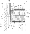
- the shielding wall 14 and the inert gas supply port 18 are provided on the ceiling surface 24e of the processing container 24.
- a shower head 54 for processing gas is incorporated in the central portion of the ceiling surface 24e of the processing container 24.
- a shielding wall 14 is used on the outer side of the ceiling surface 24e in the radial direction of the shower head 54.
- the shielding wall 14 is formed in a cylindrical shape, for example, and is provided separately from the shower head 54.
- the inert gas supply port 18 is provided between the shielding wall 14 and the inner wall 24c of the processing container 24.
- a plurality of the inert gas supply ports 18 are evenly arranged in the circumferential direction, open to the ceiling surface 24e of the processing container 24, and follow the shielding wall 14 from the upper end 14a to the lower end of the shielding wall 14. Is configured to supply an inert gas to the ceiling.
- the processing container 24 is divided into an upper chamber 100 in which the substrate holding table 12 is arranged and a lower chamber 102 in which the exhaust unit is connected.
- the upper chamber 100 and the lower chamber 102 are partitioned by a partition wall 104, and the partition wall 104 is formed with a communication hole 104a for communicating the upper chamber 100 and the lower chamber 102.
- the board holding base 12 is supported by, for example, a plurality of shafts 46.
- the shaft 46 and the substrate holding base 12 are moved up and down by the operation of the elevating mechanism 48.
- the configuration of the processing container 24 and the elevating mechanism 48 may be the same as those of the first embodiment.
- the substrate 30 is carried into the processing container 24 in a state where the substrate holding table 12 is lowered.
- the carried-in substrate 30 is supported in a horizontal posture on a lift pin 36 protruding from the surface of the substrate holding table 12.
- the elevating mechanism 48 raises the substrate holding table 12, so that the substrate 30 is supported by the upper surface 38 (specifically, the mounting surface 38a) of the substrate holding table 12.
- a processing space 32 is formed between the upper surface 38 of the substrate holding table 12 and the facing surface 52 of the shower head 54. Further, the processing space 32 and the outer circumference 12b of the substrate holding table 12 are surrounded by the shielding wall 14.
- the processing gas is dispersed and supplied to the processing space 32 by the shower head 54 provided on the ceiling surface 24e of the processing container 24.
- the inert gas enters the processing container 24 from, for example, the position of the upper end 14a of the shielding wall 14 or the inert gas supply port 18 located higher than the upper end 14a, and shields from the upper end to the lower end of the shielding wall 14. It is supplied along the wall 14.
- the processing gas emitted from the processing space 32 passes through the processing gas flow path 56 between the shielding wall 14 and the substrate holding table 12, and when it passes through the processing gas flow path 56, joins with the inert gas and is inactive. It is mixed with the gas and reaches the gas mixing section 22 below.
- the MFC and the valve that control the supply of the processing gas from the processing gas supply port 16 and the supply of the inert gas from the inert gas supply port 18 also have the same structure as that of the first embodiment, although not shown. Is used.
- the distance between the board 30 and the facing surface 52 is controlled to be, for example, 2 cm or less.
- the volume of the processing space 32 can be limited to the extent that the above-mentioned effect can be practically obtained.
- the distance between the substrate 30 and the facing surface 52 is controlled to be, for example, 0.5 cm or more. By setting this distance to 0.5 cm or more, it is possible to prevent the bias of the temperature distribution on the lower surface of the shower head 54 from affecting the in-plane temperature distribution on the substrate 30.
- the capacity of the processing space 32 is adjusted by the control of the elevating mechanism 48 within the range where the outer circumference 12b of the substrate holding table 12 and the shielding wall 14 overlap.
- the vertical length from the outer upper surface 38b of the substrate holding table 12 to the lower end of the shielding wall 14 is, for example, 5 cm or more. By setting this length to 5 cm or more, it is possible to prevent gas other than the processing gas from flowing into the processing space 32 through the processing gas flow path 56. Further, in this state, the radial distance between the outer circumference 12b of the substrate holding table 12 and the shielding wall 14 in the radial direction is, for example, 1 cm or less. This interval corresponds to the width of the processing gas flow path 56 in the radial cross section of the substrate holding table 12.
- this interval By setting this interval to 1 cm or less, it is possible to prevent gas other than the processing gas from flowing into the processing space 32 through the processing gas flow path 56. Moreover, this interval is 0.1 cm or more. By setting this interval to 0.1 cm or more, the practical conductance of the processing gas flow path 56 can be ensured.
- the substrate processing devices 10 and 20 for processing the substrates 30 one by one have been described, but the present invention is not limited to this, and a batch type apparatus in which a plurality of substrates 30 are arranged horizontally in the processing container 24 may be used. ..
- the manufacturing process of the semiconductor device has been described above, the disclosed technology according to the embodiment can be applied to other than the manufacturing process of the semiconductor device.
- substrate processing such as a liquid crystal device manufacturing process, a solar cell manufacturing process, a light emitting device manufacturing process, a glass substrate processing process, a ceramic substrate processing process, and a conductive substrate processing process.
Landscapes
- Engineering & Computer Science (AREA)
- Physics & Mathematics (AREA)
- Condensed Matter Physics & Semiconductors (AREA)
- General Physics & Mathematics (AREA)
- Manufacturing & Machinery (AREA)
- Computer Hardware Design (AREA)
- Microelectronics & Electronic Packaging (AREA)
- Power Engineering (AREA)
- Design And Manufacture Of Integrated Circuits (AREA)
- Encapsulation Of And Coatings For Semiconductor Or Solid State Devices (AREA)
Priority Applications (3)
| Application Number | Priority Date | Filing Date | Title |
|---|---|---|---|
| PCT/JP2020/011754 WO2021186562A1 (ja) | 2020-03-17 | 2020-03-17 | 基板処理装置、半導体装置の製造方法及びプログラム |
| JP2022508665A JP7529764B2 (ja) | 2020-03-17 | 2020-03-17 | 基板処理装置、半導体装置の製造方法及びプログラム |
| TW110106856A TWI775328B (zh) | 2020-03-17 | 2021-02-26 | 基板處理裝置,半導體裝置的製造方法及程式 |
Applications Claiming Priority (1)
| Application Number | Priority Date | Filing Date | Title |
|---|---|---|---|
| PCT/JP2020/011754 WO2021186562A1 (ja) | 2020-03-17 | 2020-03-17 | 基板処理装置、半導体装置の製造方法及びプログラム |
Publications (1)
| Publication Number | Publication Date |
|---|---|
| WO2021186562A1 true WO2021186562A1 (ja) | 2021-09-23 |
Family
ID=77770981
Family Applications (1)
| Application Number | Title | Priority Date | Filing Date |
|---|---|---|---|
| PCT/JP2020/011754 Ceased WO2021186562A1 (ja) | 2020-03-17 | 2020-03-17 | 基板処理装置、半導体装置の製造方法及びプログラム |
Country Status (3)
| Country | Link |
|---|---|
| JP (1) | JP7529764B2 (enExample) |
| TW (1) | TWI775328B (enExample) |
| WO (1) | WO2021186562A1 (enExample) |
Cited By (1)
| Publication number | Priority date | Publication date | Assignee | Title |
|---|---|---|---|---|
| KR102843769B1 (ko) * | 2024-05-24 | 2025-08-08 | 주식회사 테스 | 기판처리장치 |
Citations (4)
| Publication number | Priority date | Publication date | Assignee | Title |
|---|---|---|---|---|
| JPH0964028A (ja) * | 1995-08-25 | 1997-03-07 | Toshiba Corp | 半導体装置の製造方法および製造装置 |
| JP2013084895A (ja) * | 2011-09-29 | 2013-05-09 | Mitsubishi Electric Corp | 基板処理装置、基板処理方法、及び太陽電池の製造方法 |
| JP2017212466A (ja) * | 2012-03-28 | 2017-11-30 | アプライド マテリアルズ インコーポレイテッドApplied Materials,Incorporated | シームレスのコバルト間隙充填を可能にする方法 |
| JP2018070906A (ja) * | 2016-10-24 | 2018-05-10 | 東京エレクトロン株式会社 | 処理装置及びカバー部材 |
Family Cites Families (6)
| Publication number | Priority date | Publication date | Assignee | Title |
|---|---|---|---|---|
| US5907188A (en) * | 1995-08-25 | 1999-05-25 | Kabushiki Kaisha Toshiba | Semiconductor device with conductive oxidation preventing film and method for manufacturing the same |
| US6869641B2 (en) * | 2002-07-03 | 2005-03-22 | Unaxis Balzers Ltd. | Method and apparatus for ALD on a rotary susceptor |
| JP2006274316A (ja) | 2005-03-28 | 2006-10-12 | Hitachi Kokusai Electric Inc | 基板処理装置 |
| JP2012237026A (ja) | 2011-05-10 | 2012-12-06 | Tokyo Electron Ltd | 成膜装置 |
| JP2015195312A (ja) * | 2014-03-31 | 2015-11-05 | 株式会社ニューフレアテクノロジー | 気相成長装置および気相成長方法 |
| JP6704008B2 (ja) * | 2018-03-26 | 2020-06-03 | 株式会社Kokusai Electric | 基板処理装置、半導体装置の製造方法および記録媒体 |
-
2020
- 2020-03-17 WO PCT/JP2020/011754 patent/WO2021186562A1/ja not_active Ceased
- 2020-03-17 JP JP2022508665A patent/JP7529764B2/ja active Active
-
2021
- 2021-02-26 TW TW110106856A patent/TWI775328B/zh active
Patent Citations (4)
| Publication number | Priority date | Publication date | Assignee | Title |
|---|---|---|---|---|
| JPH0964028A (ja) * | 1995-08-25 | 1997-03-07 | Toshiba Corp | 半導体装置の製造方法および製造装置 |
| JP2013084895A (ja) * | 2011-09-29 | 2013-05-09 | Mitsubishi Electric Corp | 基板処理装置、基板処理方法、及び太陽電池の製造方法 |
| JP2017212466A (ja) * | 2012-03-28 | 2017-11-30 | アプライド マテリアルズ インコーポレイテッドApplied Materials,Incorporated | シームレスのコバルト間隙充填を可能にする方法 |
| JP2018070906A (ja) * | 2016-10-24 | 2018-05-10 | 東京エレクトロン株式会社 | 処理装置及びカバー部材 |
Cited By (1)
| Publication number | Priority date | Publication date | Assignee | Title |
|---|---|---|---|---|
| KR102843769B1 (ko) * | 2024-05-24 | 2025-08-08 | 주식회사 테스 | 기판처리장치 |
Also Published As
| Publication number | Publication date |
|---|---|
| TWI775328B (zh) | 2022-08-21 |
| JPWO2021186562A1 (enExample) | 2021-09-23 |
| TW202205477A (zh) | 2022-02-01 |
| JP7529764B2 (ja) | 2024-08-06 |
Similar Documents
| Publication | Publication Date | Title |
|---|---|---|
| JP6270952B1 (ja) | 基板処理装置、半導体装置の製造方法および記録媒体。 | |
| JP5982758B2 (ja) | マイクロ波照射装置 | |
| JP6240695B2 (ja) | 基板処理装置、半導体装置の製造方法及びプログラム | |
| KR102311459B1 (ko) | 기판 처리 장치, 반도체 장치의 제조 방법, 및 프로그램 | |
| KR20200115163A (ko) | 기판의 에칭 장치 및 에칭 방법 | |
| US20100227478A1 (en) | Substrate processing apparatus and method of manufacturing semiconductor | |
| JP6318139B2 (ja) | 基板処理装置、半導体装置の製造方法及びプログラム | |
| KR20200031032A (ko) | 리프팅 핀 조립체, 정전 척 및 이를 구비한 처리 장치 | |
| US12106998B2 (en) | Substrate processing apparatus, substrate processing method, non-transitory computer-readable recording medium and method of manufacturing semiconductor device | |
| JP2019212923A (ja) | 基板処理装置 | |
| WO2012153591A1 (ja) | 成膜装置 | |
| WO2018179496A1 (ja) | 半導体装置の製造方法、基板処理装置およびプログラム | |
| TWI761758B (zh) | 半導體裝置的製造方法、基板處理裝置及記錄媒體 | |
| WO2021186562A1 (ja) | 基板処理装置、半導体装置の製造方法及びプログラム | |
| KR20180006836A (ko) | 반도체 장치의 제조 방법, 기록 매체 및 기판 처리 장치 | |
| US20250115996A1 (en) | Substrate Processing Method, Method of Manufacturing Semiconductor Device, Non-transitory Computer-readable Recording Medium and Substrate Processing Apparatus | |
| CN111755359B (zh) | 基板处理装置、反应管以及半导体装置的制造方法 | |
| US20250006512A1 (en) | Substrate processing apparatus, substrate processing method, method of manufacturing semiconductor device and non-transitory computer-readable recording medium | |
| JP4880408B2 (ja) | 基板処理装置、基板処理方法、半導体装置の製造方法、メインコントローラおよびプログラム | |
| US20200173025A1 (en) | Substrate Processing Apparatus | |
| US20240047194A1 (en) | Substrate processing method and substrate processing apparatus | |
| KR20250144889A (ko) | 기판 처리 방법, 반도체 장치의 제조 방법, 기판 처리 장치 및 프로그램 | |
| JP2003151970A (ja) | 基板処理装置 | |
| CN120500739A (zh) | 基板处理装置、基板处理方法、半导体装置的制造方法以及程序 | |
| WO2017138183A1 (ja) | 基板処理装置、継手部および半導体装置の製造方法 |
Legal Events
| Date | Code | Title | Description |
|---|---|---|---|
| 121 | Ep: the epo has been informed by wipo that ep was designated in this application |
Ref document number: 20925894 Country of ref document: EP Kind code of ref document: A1 |
|
| ENP | Entry into the national phase |
Ref document number: 2022508665 Country of ref document: JP Kind code of ref document: A |
|
| NENP | Non-entry into the national phase |
Ref country code: DE |
|
| 122 | Ep: pct application non-entry in european phase |
Ref document number: 20925894 Country of ref document: EP Kind code of ref document: A1 |