WO2021186513A1 - 内燃機関の吸気構造 - Google Patents
内燃機関の吸気構造 Download PDFInfo
- Publication number
- WO2021186513A1 WO2021186513A1 PCT/JP2020/011549 JP2020011549W WO2021186513A1 WO 2021186513 A1 WO2021186513 A1 WO 2021186513A1 JP 2020011549 W JP2020011549 W JP 2020011549W WO 2021186513 A1 WO2021186513 A1 WO 2021186513A1
- Authority
- WO
- WIPO (PCT)
- Prior art keywords
- passage
- intake
- tumble
- valve
- internal combustion
- Prior art date
Links
- 238000002485 combustion reaction Methods 0.000 title claims abstract description 102
- 238000005192 partition Methods 0.000 claims abstract description 20
- 235000014676 Phragmites communis Nutrition 0.000 claims description 84
- 238000011144 upstream manufacturing Methods 0.000 claims description 27
- 238000000465 moulding Methods 0.000 claims description 8
- 239000000446 fuel Substances 0.000 abstract description 39
- 238000000638 solvent extraction Methods 0.000 abstract description 3
- 238000002347 injection Methods 0.000 description 12
- 239000007924 injection Substances 0.000 description 12
- 230000005540 biological transmission Effects 0.000 description 10
- 239000000203 mixture Substances 0.000 description 9
- 239000003054 catalyst Substances 0.000 description 6
- 239000012212 insulator Substances 0.000 description 6
- 238000000889 atomisation Methods 0.000 description 4
- 238000005266 casting Methods 0.000 description 2
- 230000007423 decrease Effects 0.000 description 2
- 230000000694 effects Effects 0.000 description 2
- 239000002828 fuel tank Substances 0.000 description 2
- 239000000463 material Substances 0.000 description 2
- 238000005452 bending Methods 0.000 description 1
- 238000003754 machining Methods 0.000 description 1
- 239000011347 resin Substances 0.000 description 1
- 229920005989 resin Polymers 0.000 description 1
Images


Classifications
-
- F—MECHANICAL ENGINEERING; LIGHTING; HEATING; WEAPONS; BLASTING
- F02—COMBUSTION ENGINES; HOT-GAS OR COMBUSTION-PRODUCT ENGINE PLANTS
- F02B—INTERNAL-COMBUSTION PISTON ENGINES; COMBUSTION ENGINES IN GENERAL
- F02B31/00—Modifying induction systems for imparting a rotation to the charge in the cylinder
- F02B31/04—Modifying induction systems for imparting a rotation to the charge in the cylinder by means within the induction channel, e.g. deflectors
-
- F—MECHANICAL ENGINEERING; LIGHTING; HEATING; WEAPONS; BLASTING
- F02—COMBUSTION ENGINES; HOT-GAS OR COMBUSTION-PRODUCT ENGINE PLANTS
- F02B—INTERNAL-COMBUSTION PISTON ENGINES; COMBUSTION ENGINES IN GENERAL
- F02B31/00—Modifying induction systems for imparting a rotation to the charge in the cylinder
- F02B31/08—Modifying induction systems for imparting a rotation to the charge in the cylinder having multiple air inlets
-
- F—MECHANICAL ENGINEERING; LIGHTING; HEATING; WEAPONS; BLASTING
- F02—COMBUSTION ENGINES; HOT-GAS OR COMBUSTION-PRODUCT ENGINE PLANTS
- F02M—SUPPLYING COMBUSTION ENGINES IN GENERAL WITH COMBUSTIBLE MIXTURES OR CONSTITUENTS THEREOF
- F02M35/00—Combustion-air cleaners, air intakes, intake silencers, or induction systems specially adapted for, or arranged on, internal-combustion engines
- F02M35/10—Air intakes; Induction systems
- F02M35/10091—Air intakes; Induction systems characterised by details of intake ducts: shapes; connections; arrangements
- F02M35/10124—Ducts with special cross-sections, e.g. non-circular cross-section
-
- F—MECHANICAL ENGINEERING; LIGHTING; HEATING; WEAPONS; BLASTING
- F02—COMBUSTION ENGINES; HOT-GAS OR COMBUSTION-PRODUCT ENGINE PLANTS
- F02M—SUPPLYING COMBUSTION ENGINES IN GENERAL WITH COMBUSTIBLE MIXTURES OR CONSTITUENTS THEREOF
- F02M35/00—Combustion-air cleaners, air intakes, intake silencers, or induction systems specially adapted for, or arranged on, internal-combustion engines
- F02M35/10—Air intakes; Induction systems
- F02M35/10242—Devices or means connected to or integrated into air intakes; Air intakes combined with other engine or vehicle parts
- F02M35/10262—Flow guides, obstructions, deflectors or the like
-
- F—MECHANICAL ENGINEERING; LIGHTING; HEATING; WEAPONS; BLASTING
- F02—COMBUSTION ENGINES; HOT-GAS OR COMBUSTION-PRODUCT ENGINE PLANTS
- F02M—SUPPLYING COMBUSTION ENGINES IN GENERAL WITH COMBUSTIBLE MIXTURES OR CONSTITUENTS THEREOF
- F02M35/00—Combustion-air cleaners, air intakes, intake silencers, or induction systems specially adapted for, or arranged on, internal-combustion engines
- F02M35/10—Air intakes; Induction systems
- F02M35/10242—Devices or means connected to or integrated into air intakes; Air intakes combined with other engine or vehicle parts
- F02M35/10275—Means to avoid a change in direction of incoming fluid, e.g. all intake ducts diverging from plenum chamber at acute angles; Check valves; Flame arrestors for backfire prevention
-
- F—MECHANICAL ENGINEERING; LIGHTING; HEATING; WEAPONS; BLASTING
- F02—COMBUSTION ENGINES; HOT-GAS OR COMBUSTION-PRODUCT ENGINE PLANTS
- F02M—SUPPLYING COMBUSTION ENGINES IN GENERAL WITH COMBUSTIBLE MIXTURES OR CONSTITUENTS THEREOF
- F02M35/00—Combustion-air cleaners, air intakes, intake silencers, or induction systems specially adapted for, or arranged on, internal-combustion engines
- F02M35/16—Combustion-air cleaners, air intakes, intake silencers, or induction systems specially adapted for, or arranged on, internal-combustion engines characterised by use in vehicles
- F02M35/162—Motorcycles; All-terrain vehicles, e.g. quads, snowmobiles; Small vehicles, e.g. forklifts
-
- F—MECHANICAL ENGINEERING; LIGHTING; HEATING; WEAPONS; BLASTING
- F02—COMBUSTION ENGINES; HOT-GAS OR COMBUSTION-PRODUCT ENGINE PLANTS
- F02M—SUPPLYING COMBUSTION ENGINES IN GENERAL WITH COMBUSTIBLE MIXTURES OR CONSTITUENTS THEREOF
- F02M35/00—Combustion-air cleaners, air intakes, intake silencers, or induction systems specially adapted for, or arranged on, internal-combustion engines
- F02M35/10—Air intakes; Induction systems
- F02M35/1015—Air intakes; Induction systems characterised by the engine type
- F02M35/1017—Small engines, e.g. for handheld tools, or model engines; Single cylinder engines
-
- Y—GENERAL TAGGING OF NEW TECHNOLOGICAL DEVELOPMENTS; GENERAL TAGGING OF CROSS-SECTIONAL TECHNOLOGIES SPANNING OVER SEVERAL SECTIONS OF THE IPC; TECHNICAL SUBJECTS COVERED BY FORMER USPC CROSS-REFERENCE ART COLLECTIONS [XRACs] AND DIGESTS
- Y02—TECHNOLOGIES OR APPLICATIONS FOR MITIGATION OR ADAPTATION AGAINST CLIMATE CHANGE
- Y02T—CLIMATE CHANGE MITIGATION TECHNOLOGIES RELATED TO TRANSPORTATION
- Y02T10/00—Road transport of goods or passengers
- Y02T10/10—Internal combustion engine [ICE] based vehicles
- Y02T10/12—Improving ICE efficiencies
Definitions
- the present invention relates to an internal combustion engine, particularly an intake structure of an internal combustion engine mounted on a saddle-mounted vehicle.
- Patent Document 1 shows an intake passage between a throttle valve and an intake valve defined as a main passage and a tumble passage along the passage direction.
- the tumble passage has a circular cross section, and the port opening between the intake valve and the intake valve valve seat, which is a flat passage, is improved so that the intake air can efficiently pass through.
- Patent Document 2 shows a flattened tumble passage, but since the tumble passage directly faces the intake valve port, the valve shaft of the intake valve interferes with the intake flow from the tumble passage. There was a challenge.
- An object of the present invention is to provide an intake structure of an internal combustion engine that easily flows between an intake valve and an intake valve valve seat, flows into a combustion chamber, strengthens a tumble flow, and can improve fuel efficiency.
- the main passage and the tumble passage are formed by the partition wall that divides the intake passage between the throttle valve and the intake valve up and down along the passage direction, and the internal combustion engine guides the intake air into the tumble passage during low load operation of the internal combustion engine.
- the intake structure of The cross section of the tumble passage formed by the partition wall is formed in a horizontally long oval shape with the passage width direction as the longitudinal direction, and one end of the tumble passage in the longitudinal direction in the cross section is an intake valve. It is characterized in that it is oriented along the tangential direction of the opening edge of the mouth, and the other end is oriented so as to gradually narrow the longitudinal width of the cross section toward the intake valve port. It is the intake structure of the internal combustion engine.
- the intake air flow during low-load operation of the internal combustion engine is rectified along a tumble passage formed in a horizontally long oval shape whose cross section is the longitudinal direction in the passage width direction, and is between the intake valve and the intake valve valve seat.
- the air-fuel mixture is easily atomized by the tumble flow during low-load operation because it easily flows into the combustion chamber, the collision interference with the intake valve seat is reduced, and the tumble flow is strengthened. Lean combustion is possible and fuel efficiency can be improved.
- the intake flow flowing through the tumble passage can flow linearly into the combustion chamber through the intake valve port, and the longitudinal width of the cross section of the tumble passage gradually narrows, so that the passage cross-sectional area gradually decreases. Since the flow velocity is gradually increased, the tumble flow is strengthened in the combustion chamber, atomization of the air-fuel mixture is further promoted, lean lean combustion is possible, and fuel efficiency can be improved.
- the internal combustion engine includes a pair of exhaust valves and intake valves whose shafts are oriented in a V shape in the front-rear direction above the combustion chamber, and the virtual extension line of the other end of the tumble passage is the said.
- a spark plug is arranged around the combustion chamber on the other end side, passing near the shaft portion of the intake valve. Therefore, the intake air flow flowing on the other end side of the tumble passage flows so as to be in contact with the valve shaft of the intake valve, so that a straight line is passed through the port opening between the upper surface of the intake valve umbrella portion and the intake valve valve seat of the intake valve port.
- a swirl flow is generated on the other end side of the intake air flow that gradually flows toward the other end side, and is ignited by the effect of guiding the air-fuel mixture to the spark plug provided on the other end side of the intake air flow.
- the ignitability of the plug is enhanced, combustion stability is obtained, lean combustion is improved, and fuel performance can be improved.
- the main passage is provided with a reed valve that closes in the intake flow during low-load operation of the internal combustion engine. Therefore, the intake air flowing through the main passage can be restricted by the reed valve during the low load operation of the internal combustion engine, the intake air flow can be mainly flowed to the tumble passage, and the tumble flow can be further enhanced.
- the reed valve is provided between the throttle valve and the inlet manifold, and the reed valve body that limits the intake flow of the main passage covers the outlet opening on the main passage side of the reed valve and has one end on the upstream side. It is attached to the reed valve body of the reed valve, and the opening side edge on the downstream side is formed in a direction parallel to the passage width direction of the tumble passage.
- the operating region of the reed valve body in the passage width direction can be formed large along the passage width direction of the tumble passage having a horizontally long cross section, the main passage side outlet opening of the reed valve can be provided large, and the main passage, The intake efficiency can be improved by reducing the flow path resistance of both tumble passages.
- the reed valve body of the reed valve is formed by a molding die that combines the main passage from the downstream side and the tumble passage from the upstream side from two directions. Therefore, due to the draft of the molding die that forms the reed valve body, the passage area of the main passage expands from the entrance to the exit, while the tumble passage contracts conversely, so that the total passage area of both passages changes. Is reduced, the disturbance of the flow velocity of the intake flow during high load operation can be prevented, and the engine performance is improved.
- the main passage side outlet opening width of the main passage side outlet opening of the reed valve body is wider than the inlet opening width of the inlet opening (82) of the reed valve body. Therefore, the intake air flow at the time of high load can be smoothly flowed to the main passage side, and the engine performance can be improved.
- the tumble passage side outlet opening is vertically adjacent to the main passage side outlet opening below the step portion provided on both sides below the main passage side outlet opening. It is provided in a narrow width. Therefore, the exit opening on the tumble passage side is narrowed by the step portion, the flow velocity of the tumble passage is increased when the load is low, lean combustion is improved, and fuel efficiency is improved.
- the intake air flow during low-load operation of the internal combustion engine is rectified along a tumble passage formed in a horizontally long oval shape whose cross section is the longitudinal direction in the passage width direction, and is between the intake valve and the intake valve valve seat.
- the air-fuel mixture is easily atomized by the tumble flow during low-load operation because it easily flows into the combustion chamber, the collision interference with the intake valve seat is reduced, and the tumble flow is strengthened. Lean combustion is possible and fuel efficiency can be improved.
- the intake flow flowing through the tumble passage can flow linearly into the combustion chamber through the intake valve port, and the longitudinal width of the cross section of the tumble passage gradually narrows, so that the passage cross-sectional area gradually decreases. Since the flow velocity is gradually increased, the tumble flow is strengthened in the combustion chamber, atomization of the air-fuel mixture is further promoted, lean lean combustion is possible, and fuel efficiency can be improved.
- FIG. 1 It is a left side side schematic view of the motorcycle 1 provided with the intake structure of the internal combustion engine which concerns on one Embodiment of this invention. It is a right cross-sectional side view along the cylinder axis C of the cylinder block, the cylinder head, the head cover and the periphery of the power unit in FIG. It is a perspective view of the upstream side of the reed valve body of a reed valve. It is a perspective view of the downstream side of the reed valve body of a reed valve. It is a perspective view of the downstream side of the reed valve body having the same orientation as FIG. 4, and shows the state in which the reed valve body is fastened to the reed valve body.
- FIG. 2 is a perspective view of a cross section substantially diagonally intersecting the cylinder axis C along the tumble passage of the cylinder head, as viewed from the head cover side, as viewed by VII-VII in FIG. It is a top perspective view of the cylinder head seen from the upper right rear view by arrow VIII in FIG.
- FIGS. 1 to 8 An intake structure of an internal combustion engine according to an embodiment of the present invention will be described with reference to FIGS. 1 to 8.
- the saddle-mounted vehicle is specifically a scooter-type motorcycle (hereinafter, simply referred to as "motorcycle").
- the arrow FR indicates the front of the vehicle
- LH indicates the left side of the vehicle
- RH indicates the right side of the vehicle
- UP indicates the upper part of the vehicle.
- FIG. 1 shows an outline of the left side surface of the motorcycle 1 provided with the intake structure of the internal combustion engine according to the present embodiment.
- the front portion 1A of the vehicle body and the rear portion 1B of the vehicle body are connected via a low floor portion 1C (footrest portion), and the vehicle body frame 2 forming the skeleton of the vehicle body is generally down. It consists of a frame 21 and a main frame 22. That is, the down frame 21 extends downward from the head pipe 20 of the front portion 1A of the vehicle body, and the lower frame portions 22a of the pair of left and right main frames 22 extending substantially horizontally from the lower end of the down frame 21 to the rear are connected.
- the main frame 22 extending diagonally rearward and upward from the rear end of the lower frame portion 22a forms a pair of left and right inclined portions 22b, and the upper portion of the inclined portion 22b is further bent and extends substantially horizontally to the rear. Is forming.
- a storage box (also called a helmet box) 11 is supported on the inclined portion 22b and the horizontal portion 22c of the main frame 22, and the passenger seat 12 is placed above the storage box (also called a helmet box).
- the handle 13 is pivotally supported by the head pipe 20 and the handle 13 is provided above, the front fork 14 extends downward, and the front wheel 15 is pivotally supported at the lower end thereof.
- a power unit support bracket 23 is projected rearward from the inclined portion 22b of the main frame 22, and a swing type power unit (hereinafter, simply referred to as “power unit”) 3 swings up and down on the power unit support bracket 23 via a link member 24.
- power unit swing type power unit
- the head pipe 20 and the down frame 21 are covered from the front and rear by the front cover 10a and the leg shield 10b of the vehicle body cover 10.
- the floor portion 1C is provided on the left and right pair of lower frame portions 22a side of the main frame 22 of the vehicle body frame 2, and the upper part of the lower frame portion 22a is covered by the floor cover 10c, and the left and right sides of the floor side cover are covered in the front-rear direction. It is covered with 10d and the lower part is covered with undercover 10e.
- a fuel tank 16 is provided in the horizontal portion 22c of the main frame 22 below the rear portion of the occupant seat 12 and above the rear wheels 17, and the inclined portion 22b and the horizontal portion 22c of the main frame 22 are body covers.
- the left and right and the rear are covered by 10f.
- a front fender 10 g is provided above the front wheel 15.
- Each of the covers 10a to 10g constituting the vehicle body cover 10 is formed of an appropriate material such as a resin material.
- the power unit 3 is provided with an internal combustion engine 4, and is provided with a power transmission unit 5 in which a belt-type continuously variable transmission 51 is internally provided from the internal combustion engine 4 to the rear.
- a reduction gear mechanism 52 transmitted from a belt-type continuously variable transmission 51 is provided at the rear of the power transmission unit 5, and a rear wheel 17 is provided on the rear axle 52a, which is an output shaft thereof.
- a rear cushion 18 is interposed between the rear portion of the power transmission portion 5 and the horizontal portion 22c at the rear portion of the main frame 22.
- the internal combustion engine 4 is a single-cylinder air-cooled 4-stroke cycle internal combustion engine that rotatably supports the crankcase 30 by directing the crankshaft 41 in the vehicle width direction, that is, in the left-right direction, and projects from the front portion of the crankcase 30.
- the cylinder block 42, the cylinder head 43, and the head cover 44 are sequentially overlapped with each other, and the cylinder axis C is fastened so as to be substantially horizontal and tilted forward.
- An inlet manifold 61 and a throttle body 62 are provided above the power unit 3 and above the cylinder head 43 to the crankcase 30, and an inlet manifold 61 is provided at the intake port inlet 45a above the cylinder head 43 that is tilted forward.
- the inlet manifold 61 is connected to the throttle body 62 by bending backward on the upstream side and extending.
- An air cleaner 64 attached to the upper part of the power transmission unit 5 is connected to the upstream side of the throttle body 62 via a connecting tube 63.
- An intake passage 6 is formed from the connecting tube 63 through the throttle body 62, the inlet manifold 61, and the intake port 45 of the cylinder head 43, and leads to the combustion chamber 32.
- the upstream exhaust pipe 48a connected to the exhaust port outlet 47a at the lower part of the cylinder head 43 is interposed with a substantially cylindrical catalyst device 49 oriented in the vehicle width direction, and purifies the exhaust gas inside the catalyst device 49.
- a catalyst such as a three-way catalyst is loaded.
- the downstream exhaust pipe 49b connected to the outlet of the catalyst device 49 bends rearward and extends rearward along the right side of the vehicle, and is connected to a muffler (not shown) on the right side of the rear wheel 17.
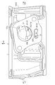
- FIG. 2 is a right sectional side view of the cylinder block 42, the cylinder head 43, the head cover 44, and the periphery thereof of the power unit 3 in FIG. 1 along the cylinder axis C.
- the crankcase 30 is composed of a left-right case half body 30L divided into left and right and a right case half body (not shown), and the left case half body 30L is extended rearward to extend the crankshaft 41 and rear.
- a power transmission unit 5 is formed in front of and behind the rear axle 52a of the wheel 17 to accommodate a transmission device including a long belt-type stepless transmission 51 (not shown) and a reduction gear mechanism 52 and the like.
- the piston 33 that reciprocates in the cylinder bore 42a of the cylinder block 42 is connected to the crankpin 41a of the crankshaft 41 of the crankcase 30 by a connecting rod 34.
- a combustion chamber 32 is formed between the top surface 33a of the piston 33 slidably fitted in the cylinder bore 42a of the cylinder block 42 and the combustion chamber ceiling surface 43a of the cylinder head 43 facing the top surface 33a.
- the throttle body 62 is fastened and connected to the inlet manifold 61 connected to the intake port inlet 45 of the cylinder head 43 in the present embodiment via a reed valve 8 described later on the upstream side. ..
- a throttle valve 62a is incorporated in the intake passage 6 and rotates around the throttle valve shaft 62b to open and close the intake passage 6 and adjust the intake flow rate.
- reference numeral 31 denotes a bracket portion that is projected upward from the upper part of the crankcase 30 and for suspending the power unit 3 on the vehicle body frame 2.
- a bracket portion 31 is pivotally supported by a power unit support bracket 23 projecting rearward from an inclined portion 22b of the main frame 22 via a link member 24, and the power unit 3 is a vehicle body. It swings up and down with respect to the frame 2.
- the rear end of the power unit 3 that swings up and down is supported by the rear cushion 18 on the horizontal portion 22c of the main frame 22.
- an inlet manifold 61 is connected to the front of the throttle body 62, that is, on the downstream side of the intake air, bends downward, and is connected to the intake port inlet 45a above the cylinder head 43 with the insulator 60 sandwiched between them. doing.
- a fuel injection valve 39 is attached to the downstream end of the inlet manifold 61, and fuel is injected toward the intake valve port 35. Since the fuel injection has a certain spread with respect to the injection center line I shown in FIG. 2, the fuel injection avoidance recess 67a for avoiding the injected fuel is provided in the main passage head inlet opening 67 on the downstream side, which will be described later. (See FIG. 6).
- a fuel hose (not shown) connected to the fuel injection valve 39 is arranged rearward and is connected to a fuel tank 16 provided above the rear wheels 17 via a fuel pump device (not shown).
- the internal combustion engine 4 employs a single-cylinder SOHC type two-valve system, and the cylinder head 43 is provided with a valve operating mechanism 9.
- a head cover 44 is overlapped and covered on the cylinder head 43 so as to cover the valve operating mechanism 9.
- an endless cam chain (not shown) is provided on one side of the crankcase 30, the cylinder block 42, and the cylinder head 43 in the crankshaft 41 direction. It is erected between the cam shaft 91 and the crank shaft 41 through the chain chamber, and the cam shaft 91 rotates at a rotation speed of 1/2 in synchronization with the crank shaft 41.
- a spark plug 40 (see FIG. 4) is fitted in the cylinder head 43 from the side opposite to the cam chain chamber (the other side in the direction of the crankshaft 41) toward the inside of the combustion chamber 32.
- the intake port 37 and the exhaust port 38 are separated from each other vertically from the intake valve port 35 and the exhaust valve port 36 opened in the combustion chamber ceiling surface 43a, respectively. It is formed by extending while curving in the direction.
- the upstream end of the intake port 37 opens upward toward the cylinder head 43 to form an intake port inlet 45, which is connected to the inlet manifold 61 to form a continuous intake passage 6 on the upstream side of the inlet manifold 61.
- Throttle body 62 is connected.
- the downstream end of the exhaust port 38 forms the exhaust port outlet 47, opens downward of the cylinder head 43, and is connected to the upstream exhaust pipe 48a (see FIG. 1).
- a cylindrical intake valve guide 71 is integrally fitted to the curved outer wall portion 37a of the intake port 37 in the cylinder head 43, and the intake valve 73 slidably supported by the intake valve guide 71 is a combustion chamber of the intake port 37. Open and close the intake valve port 35 facing 32. Further, the exhaust valve 74 slidably supported by the exhaust valve guide 72 integrally fitted to the curved outer wall portion 38a of the exhaust port 38 in the cylinder head 43 faces the combustion chamber 32 of the exhaust port 38. Open and close 36.
- the intake valve 73 and the exhaust valve 74 are urged upward by the valve spring 75 so that the umbrella portions 73a and 74a both close the intake valve port 35 and the exhaust valve port 36 facing the combustion chamber 32.
- the intake cam of the cam shaft 90, the intake rocker arm 91 that swings in contact with the exhaust cam, and the exhaust rocker arm 92 push down the stem ends 73b and 74b of the intake valve 73 and the exhaust valve 74, and the intake valve 73,
- the exhaust valve 74 opens, and the intake port 37 and the combustion chamber 32 communicate with each other, and the exhaust port 38 and the combustion chamber 32 communicate with each other to perform intake and exhaust at predetermined timings.
- a vertical rotating vortex of the fuel / air mixture (rotating vortex on a virtual plane along the cylinder axis C) in the combustion chamber 32. )
- a tumble flow T and a lateral rotating vortex (a rotating vortex on a virtual plane orthogonal to the cylinder axis C), that is, an intake structure for giving a swirl flow S
- An inlet manifold 61 is connected to the upstream end of the intake port 37 of the internal combustion engine 4 via an insulator 60 to form a continuous intake passage 6, and a reed valve 8 described later is located upstream of the inlet manifold 61.
- the throttle body 62 is connected via.
- the throttle body 62 has an intake passage 62c having a substantially circular cross section forming a part of an intake passage 6 connected to a combustion chamber 32 of the internal combustion engine 4, and an air cleaner 64 (FIG. 1) is connected.
- the throttle body 62 is rotatably supported in the throttle body 62 by a throttle valve shaft 62b oriented perpendicularly to the intake flow direction F of the intake passage 62c, that is, perpendicular to the central axis X of the intake passage 62c and substantially horizontally. It is provided with a single butterfly type throttle valve 62a that can variably control the flow path area of the intake passage 62c and open and close the intake passage 62c.
- the throttle valve 62a can be rotated clockwise in the drawing of FIG. 2 in the valve opening direction by an operation of the driver or the like, and is urged clockwise in the valve closing direction by a return spring (not shown).
- the intake passage 62c of the throttle body 62 is oriented substantially horizontally.
- the intake passage 6 is continuously divided into upper and lower parts along the intake flow direction by the partition wall 65 from the inlet manifold 61 to the intake port 37, and the passing intake air passes through the tumble flow T in the combustion chamber 32. It is divided into a tumble passage 6A on the lower side in the drawing and a main passage 6B on the upper side in the drawing excluding the tumble passage 6A which are configured to generate.
- the "tumble passage” is an intake passage for generating a tumble flow T in the combustion chamber 32 when the throttle valve 62a has a low opening degree, that is, when the load of the internal combustion engine 4 is low.
- the vertical arrangement of the tumble passage 6A and the main passage 6B is not limited to that of the embodiment.
- the partition wall 65 is configured such that the inlet manifold side partition wall 65A, the insulator side partition wall 65B, and the intake port side partition wall 65C are continuously positioned from the upstream side to the downstream side of the intake air flow.
- the main passage 6B on the upper side of the drawing and the tumble passage 6A on the lower side of the drawing divide the intake passage 6 on the downstream side of the throttle body 62 into the upper and lower parts of the drawing by a vertical partition wall 65 from the inlet manifold 61 to the intake port 37.
- a lead valve 8 formed in a substantially triangular shape in the side view cross section of the intake passage 6 is interposed between the throttle body 62 and the inlet manifold 61. Has been done.
- FIG. 3 is a perspective view of the upstream side of the reed valve body 81 of the reed valve 8, and the intake passage 6 is opened in the mounting flange portion 85, and the main passage side is behind the valve intake passage 80 inside the intake passage 6.
- the exit opening 86 and the exit opening 84 on the tumble passage side can be seen.
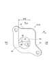
- FIG. 4 is a perspective view of the reed valve body 81 of the reed valve 8 on the downstream side. The back portion of the mounting flange portion 85, the main passage side outlet opening 86 of the inclined surface 81a, and the tumble passage side of the downstream end portion 83.
- the exit opening 84 and the like are shown.
- FIG. 5 is a perspective view of the downstream side of the reed valve 8 having the same orientation as that of FIG. 4, showing a state in which the reed valve body 87 is fastened to the reed valve body 81.
- the reed valve 8 includes a reed valve body 81 that forms the whole, and a mounting flange portion 85 thereof is sandwiched and fastened between a downstream end portion of the throttle body 62 and an upstream end portion of the inlet manifold 61.
- An inlet opening 82 that matches the downstream opening 62d of the throttle body 62 is provided on the surface of the reed valve body 81 that is attached to the throttle body 62, and a valve that communicates with the intake passage 62c of the throttle body 62 inside the reed valve body 81.
- the intake passage 80 is formed.
- the downstream end 83 of the reed valve body 81 is formed with a tumble passage side outlet opening 84 that abuts on the upstream end 65Aa of the inlet manifold side partition wall 65A and matches the upstream end opening 6Aa of the tumble passage 6A of the inlet manifold 61. Will be done.
- the upper portion of the reed valve body 81 is formed so as to be inclined from the back portion of the mounting flange portion 85 to the lower portion on the downstream side of the reed valve 8.
- the main passage side outlet opening 86 that communicates the 80 with the main passage 6B of the inlet manifold 61 is formed.
- a lead valve body 87 is fastened to the outer surface of the main passage side outlet opening 86 so as to cover the main passage side outlet opening 86, and one end portion 87a on the upstream side is fastened to the back portion of the flange portion 85 by a lead valve body screw 87c. ..
- the opening side edge 87b on the other end side of the reed valve body 87 is a swing free end, and comes into contact with the reed valve body 81 above the tumble passage side outlet opening 84 of the downstream end portion 83 of the reed valve body 81.
- the main passage side outlet opening 86 is kept closed, and the inlet manifold 61 is tumbled exclusively from the valve intake passage 80 in the reed valve body 81.
- the intake air flows into the passage 6A.
- the opening side edge portion 87b on the downstream side of the reed valve body 87 Bends to open the outlet opening 86 on the main passage side, and the intake air flows from the valve intake passage 80 in the reed valve body 81 to the main passage 6B of the inlet manifold 61.
- the upstream end opening 6Aa of the tumble passage 6A of the intake passage 6 of the inlet manifold 61 connected to the downstream side of the valve intake passage 80 of the reed valve 8 is the tumble passage side outlet opening 84 of the downstream end 83 of the reed valve 8.
- the upstream end opening 6Ba of the main passage 6B is connected to the downstream side of the main passage side outlet opening 86 of the inclined surface 81a of the reed valve 8 and is opened.
- the throttle valve 62a is provided near the downstream end of the intake passage 70 of the throttle body 62, and the reed valve 8 has a tumble passage side outlet opening 84 and a main passage side outlet. Since the opening 86 is connected via the valve intake passage 80 having a suppressed volume, the response of the reed valve body 87 of the main passage side outlet opening 86 to the state of the throttle valve 62a is quick, and the tumble passage 6A and the main passage The response of 6B intake flow switching is high.
- the reed valve 8 is provided between the throttle body 62 and the inlet manifold 61, and the tumble passage side outlet opening 84 has a cross section below the intake passage 6 as shown in FIGS. 4 and 5. 69 is horizontally long and wide, and the opening cross section is large.
- the reed valve body 87 that limits the intake flow of the main passage 6B covers the main passage side outlet opening 86 of the reed valve 8 and has one end portion 87a on the upstream side attached to the reed valve body 81 and an opening side edge portion on the downstream side. 87b is formed in a direction parallel to the passage width direction of the tumble passage 6A.
- the main passage side outlet opening 86 of the reed valve 8 can be provided large. It is possible to reduce the flow path resistance of both the main passage 6B and the tumble passage 6A to improve the intake efficiency.
- the reed valve body 81 of the reed valve 8 is integrally molded by a molding die, and the main passage 6B in the reed valve body 81 is molded by a molding die combined from the downstream side.
- the tumble passage 6A in 81 is formed by a mold that is combined from the upstream side, and is formed by a mold that is combined from two directions with each other. Therefore, as shown in FIG. 2, the main passage 9B in the reed valve 8 is formed at an angle ⁇ that spreads toward the downstream side due to the draft of the molding die.
- the tumble passage 6A in the reed valve 8 is formed at an angle ⁇ that narrows toward the downstream side due to the draft of the molding die.
- the passage area of the main passage 6B increases from the entrance to the exit, while the tumble passage 6A is reduced in reverse, so that both passages 6A and 6B
- the change in the total passage area is reduced, the turbulence of the intake flow flow velocity during high-load operation can be prevented, and the engine performance is improved.
- a fuel injection valve 39 is attached to the inlet manifold 61 so as to penetrate the main passage 6B from above and outside and inject and supply fuel toward the intake valve port 35.
- the fuel injection valve 39 is arranged in the inlet manifold 61, but a direct injection structure in which the fuel injection valve 39 is arranged in the cylinder head 43 or the cylinder block 42 and fuel is injected into the combustion chamber 32 is also available. good.
- the tumble passage side outlet opening 84 of the downstream end 83 of the reed valve 8 is formed in a horizontally long oval cross section that is long in the passage width direction. Therefore, the tumble passage 6A of the inlet manifold 61 connected to the outlet opening 84 on the tumble passage side is also formed by partitioning the intake passage 6 by the partition wall 65A on the inlet manifold side, and the cross section 69 is horizontally long in the passage width direction. It is formed in the horizontally long cross section of the oval shape.
- the main passage side outlet opening width 86W of the main passage side outlet opening 86 of the reed valve body 81 shown in FIG. 4 is formed wider than the inlet opening width 82W of the inlet opening 82 of the reed valve body 81 shown in FIG. Has been done. Therefore, the intake air flow of the internal combustion engine 4 when the load is high can be smoothly flowed to the main passage 6B side, and the engine performance can be improved.
- the tumble passage side outlet opening 84 is a stepped portion 88 provided on both lower sides of the main passage side outlet opening 86. It is provided vertically adjacent to the main passage side outlet opening 86 and narrower than the main passage side outlet opening 86 below the narrowed portion. Therefore, the tumble passage side outlet opening 84 is narrowed by the step portion 88, the flow velocity of the tumble passage 6A is increased when the load of the internal combustion engine 4 is low, lean combustion is improved, and fuel efficiency is improved.
- the reed valve body 87 of the reed valve 8 that closes in the intake flow during the low load operation of the internal combustion engine 4 is provided in the main passage 6B of the intake passage 6, the internal combustion engine 4 is low.
- the reed valve body 87 of the reed valve 8 can limit the intake air flowing through the main passage 6B, and the intake air flow can mainly flow to the tumble passage 6A, so that the tumble flow T in the combustion chamber 32 can be further increased.
- the tumble flow T shown by the alternate long and short dash line in FIG. 2 schematically shows the tumble flow T in the combustion chamber 32 when the piston 33 descends in the cylinder bore 42a as shown by the alternate long and short dash line. ..
- FIG. 6 is a top view of the cylinder head 43 viewed from the arrow VI-VI in FIG. 2, and the intake port inlet 45 is shown on the intake side flange surface 43b to which the inlet manifold 61 is fastened via the insulator 60.
- the intake port inlet 45 is partitioned by the intake port side partition wall 65C, and the tumble passage head inlet opening 66 and the main passage head inlet opening 67 are opened.
- the tumble passage head inlet opening 66 is also the tumble passage 6A of the inlet manifold 61.
- it is formed in a horizontally long cross section 69 having a horizontally long oval shape that is long in the passage width direction.
- the main passage head inlet opening 67 is formed with a fuel injection avoiding recess 67a for avoiding fuel injected from the fuel injection valve 39 (see FIG. 2).
- the tumble passage 6A of the cylinder head 43 is formed by casting when the cylinder head 43 is cast, but it may be formed by machining after the cylinder head 43 is formed. However, as described above, the tumble passage 6A is preferably formed at the time of casting because the cross section 69 is formed in a horizontally long oval-shaped horizontally long cross section that is long in the passage width direction. As shown in FIG. 2, the tumble passage 6A of the cylinder head 43 is formed so that the passage cross-sectional height h is uniform from the tumble passage head inlet opening 66 to the tumble passage outlet 68.
- the orientation of the tumble passage 6A of the cylinder head 43 and the passage cross-sectional height h are such that the intake flow f that has passed through the tumble passage 6A of the cylinder head 43 and is ejected into the intake port 37 is shown by a chain double-dashed line in FIG. , It is set to face between the umbrella portion 73a of the opened intake valve 73 and the intake valve valve seat 77.
- an intake valve guide 71 fitted to the curved outer wall portion 37a of the intake port 37 and an intake valve 73 slidably supported by the intake valve guide 71 are provided behind the main passage head inlet opening 67. The shaft of is shown.
- the cross section 69 of the tumble passage 6A formed by the partition wall 65 in the intake passage 6 is formed in a horizontally long oval cross section long in the passage width direction, so that the internal combustion engine 4 can be operated at a low load.
- the intake air flow at the time is rectified along the tumble passage 6A, the collision interference with the intake valve seat 77 of the intake valve port 35 is reduced and flows into the combustion chamber 32, and the tumble flow T is strengthened, so that the load is low. Atomization of the air-fuel mixture by the tumble flow T during operation is promoted, rapid combustion and lean combustion are possible, and fuel efficiency can be improved.
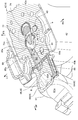
- FIG. 7 is a perspective view of a cross section substantially diagonally intersecting the cylinder axis C along the tumble passage 6A of the cylinder head 43, as viewed from the head cover 44 side, as viewed by VII-VII in FIG. ..
- one end 69a in the longitudinal direction of the cross section 69 of the tumble passage 6A is oriented along the tangential direction of the opening edge 35a of the intake valve port 35, and the other end 69b is directed to the intake valve port 35. It is oriented so that the width w in the longitudinal direction of the cross section 69 is gradually narrowed.
- the intake flow flowing through the tumble passage 6A can flow linearly into the combustion chamber 32 through the intake valve port 35, and the longitudinal width w of the cross section 69 of the tumble passage 6A is gradually narrowed. Therefore, the cross-sectional area of the passage is gradually reduced and the flow velocity is gradually increased, so that the tumble flow T is strengthened in the combustion chamber 32, the atomization of the air-fuel mixture is further promoted, and leaner combustion is possible, which enables fuel efficiency. Can be improved.
- a pair of intake valves 73 and exhaust valves 74 are oriented above the combustion chamber 32 by opening the shaft portions 73c and the shaft portions 74c in a V shape in the front-rear direction. Being prepared.
- a virtual extension line b in the passage direction of the other end 69b of the tumble passage 6A passes near the shaft portion 73c of the intake valve 73, and the combustion chamber on the other end 69b side. Spark plugs 40 are arranged around 32.
- the intake air flowing out from the other end 69b side of the tumble passage 6A flows so as to be in contact with the shaft portion 73c of the intake valve 73, so that the upper surface of the umbrella portion 73a of the intake valve 73 and the intake valve valve of the intake valve port 35
- the intake flow on the other end 69b side that directly flows in through the port opening 78 between the seat 77 and the seat 77 comes into contact with the shaft portion 73c to reduce the flow velocity, and a swirl flow S toward the other end 69b side is generated. Therefore, the tumble flow T is inclined in the swirl flow S direction to guide the air-fuel mixture to the spark plug 40 provided on the other end 69b side of the tumble passage 6A, and the ignitability of the spark plug 40 is enhanced.
- the swirl flow S shown by the alternate long and short dash line in FIG. 7 schematically represents the swirl flow S in the combustion chamber 32 when the piston 33 descends in the cylinder bore 42a as shown by the alternate long and short dash line in FIG. It shows.
- the tumble passage 80A is a side view with respect to a cross section along the cylinder axis C, and is an umbrella portion 73a when the intake valve 73 is opened and an exhaust valve port of the intake valve port 35. It is formed in a straight line facing the intake valve valve seat 77 on the 36 side. Therefore, as shown by the alternate long and short dash line in FIG. 2, the intake flow f flowing out of the tumble passage 6A is passed above the umbrella portion 73a of the intake valve 73, and collision interference with the intake valve seat 77 is reduced. Since it can be directly flowed into the cylinder bore 42a, the tumble flow T is likely to occur in the combustion chamber 32.
- FIG. 8 is a perspective view of the upper surface of the cylinder head 43 as viewed from the upper right rear side as viewed from the upper right rear view of FIG. 2 in FIG. It is shown from the right side that the spark plug 40 is attached.
- the upper surface 61a of the inlet manifold 61 is a reed valve body of the main passage 6B of the inserted reed valve 8. Since 87 forms a substantially rectangular shape wide in the width direction of the passage and moves up and down upward, it is formed in a plane so as to match it (see also FIG. 2). Therefore, the upper part of the inlet manifold 61 is made compact, and the space for other equipment, piping, etc. is increased.
Landscapes
- Engineering & Computer Science (AREA)
- Chemical & Material Sciences (AREA)
- Combustion & Propulsion (AREA)
- Mechanical Engineering (AREA)
- General Engineering & Computer Science (AREA)
- Cylinder Crankcases Of Internal Combustion Engines (AREA)
Abstract
Description
また、例えば下記特許文献2には、タンブル通路を扁平にしたものが示されるが、タンブル通路が吸気弁口に直に臨むので、タンブル通路からの吸気流に吸気弁の弁軸が干渉するという課題があった。
スロットル弁と吸気弁との間の吸気通路を通路方向に沿って上下に仕切る仕切り壁により、主通路とタンブル通路が形成され、内燃機関の低負荷運転時に吸気を前記タンブル通路内へ導く内燃機関の吸気構造において、
前記仕切り壁により形成された前記タンブル通路の横断面が、通路幅方向を長手方向とする横長の長円形状に形成され、前記タンブル通路の前記横断面における長手方向の一方の端が、吸気弁口の開口縁の接線方向に沿うように配向され、他方の端が、前記吸気弁口に向かって前記横断面の長手方向幅を徐々に幅狭とするように配向されたことを特徴とする内燃機関の吸気構造である。
内燃機関の低負荷運転時の吸気流が、横断面が通路幅方向を長手方向とする横長の長円形状に形成されたタンブル通路に沿って整流され、吸気弁と吸気弁バルブシートとの間に流入し易く、吸気バルブシートとの衝突干渉が低減されて燃焼室に流入し、タンブル流が強化されるため、低負荷運転時のタンブル流による混合気の霧化が促進され、急速燃焼およびリーン燃焼が可能となり、燃費性能を向上させることができる。
また、タンブル通路を流れる吸気流が、吸気弁口を通し直線的に燃焼室に流入でき、且つタンブル通路の横断面の長手方向幅が徐々に幅狭となるので通路断面積が徐々に減じて、流速が徐々に高められるため、燃焼室においてタンブル流が強化され、混合気の霧化がより促進され、よりリーンなリーン燃焼が可能となり燃費性能を向上させることができる。
前記内燃機関は、燃焼室上方に互いの軸部が前後にV型に開いて配向された一対の排気弁と前記吸気弁とを備え、前記タンブル通路の前記他方の端の仮想延長線が前記吸気弁の軸部近傍を通り、前記他方の端側の前記燃焼室の周囲に点火プラグが配置される。
そのため、タンブル通路の他方の端側を流れる吸気流が吸気弁の弁軸と接するように流れるため、吸気弁の傘部の上面と吸気弁口の吸気弁バルブシートとの間のポート開口を通して直線的に流入する吸気流の他方の端側に流速を減じて他方の端側に向かうスワール流が発生し、吸気流の他方の端側に設けられた点火プラグへ混合気を導く効果によって、点火プラグでの着火性が高められ、燃焼安定性が得られてリーン燃焼が向上し、燃料性能を向上させることができる。
前記主通路には、前記内燃機関の低負荷運転時の吸気流において閉弁するリードバルブが設けられる。
そのため、内燃機関の低負荷運転時にリードバルブにより主通路を流れる吸気を制限でき、吸気流を主にタンブル通路に流すことができ、タンブル流をより高めることができる。
前記リードバルブは、前記スロットル弁とインレットマニホールドとの間に設けられ、前記主通路の吸気流を制限するリード弁体は、前記リードバルブの主通路側出口開口を覆って上流側の一端部が前記リードバルブのリードバルブボディに取付けられ、下流側の開口側縁部は前記タンブル通路の通路幅方向と平行な向きに形成される。
そのため、リード弁体の通路幅方向稼働領域を、横断面が横長のタンブル通路の通路幅方向に沿って大きく形成できるので、リードバルブの主通路側出口開口を大きく設けることができ、主通路、タンブル通路双方の流路抵抗を減らして吸気効率を向上できる。
前記リードバルブの前記リードバルブボディは、前記主通路を下流側から、前記タンブル通路を上流側から、相互に2方向から組み合わされる成形型により成形されてなる。
そのため、リードバルブボディを成形する成形型の抜き勾配により、主通路は入り口から出口に向かって通路面積が拡大し、一方、タンブル通路は逆に縮小されるため、両通路の合計通路面積の変化が低減され、高負荷運転時の吸気流の流速の乱れを防止でき、エンジン性能が向上する。
前記リードバルブボディの前記主通路側出口開口の主通路側出口開口幅は、前記リードバルブボディの入口開口(82)の入口開口幅よりも幅広い。
そのため、高負荷時の吸気流を滑らかに主通路側に流すことができ、エンジン性能を高めることができる。
前記リードバルブボディ内のバルブ吸気路において、タンブル通路側出口開口は、前記主通路側出口開口の下部両脇に設けられた段部により狭められた下方に、同主通路側出口開口と上下隣接して幅狭に設けられる。
そのため、段部によりタンブル通路側出口開口が絞られ、低負荷時にタンブル通路の流速を高めて、リーン燃焼が向上し、燃費が向上する。
内燃機関の低負荷運転時の吸気流が、横断面が通路幅方向を長手方向とする横長の長円形状に形成されたタンブル通路に沿って整流され、吸気弁と吸気弁バルブシートとの間に流入し易く、吸気バルブシートとの衝突干渉が低減されて燃焼室に流入し、タンブル流が強化されるため、低負荷運転時のタンブル流による混合気の霧化が促進され、急速燃焼およびリーン燃焼が可能となり、燃費性能を向上させることができる。
また、タンブル通路を流れる吸気流が、吸気弁口を通し直線的に燃焼室に流入でき、且つタンブル通路の横断面の長手方向幅が徐々に幅狭となるので通路断面積が徐々に減じて、流速が徐々に高められるため、燃焼室においてタンブル流が強化され、混合気の霧化がより促進され、よりリーンなリーン燃焼が可能となり燃費性能を向上させることができる。
なお、本明細書の説明および請求の範囲における前後左右上下等の向きは、本実施形態に係る内燃機関を鞍乗型車両に搭載した場合の、鞍乗型車両の車両の向きに従うものとする。本実施形態において鞍乗型車両は、具体的にはスクータ型自動二輪車(以下、単に「自動二輪車」という)である。
また、図中矢印FRは車両前方を、LHは車両左方を、RHは車両右方を、UPは車両上方を、それぞれ示す。
本実施形態の自動二輪車1においては、車体前部1Aと車体後部1Bとが、低いフロア部1C(足載部)を介して連結されており、車体の骨格をなす車体フレーム2は、概ねダウンフレーム21とメインフレーム22とからなる。
すなわち車体前部1Aのヘッドパイプ20からダウンフレーム21が下方へ延出し、ダウンフレーム21の下端から後方へ略水平に延びる左右一対のメインフレーム22のロアフレーム部22aが接続する。ロアフレーム部22aの後端から斜め後上方に延びるメインフレーム22は左右一対の傾斜部22bを形成し、傾斜部22bの上部がさらに屈曲して後方に略水平に延びた左右一対の水平部22cを形成している。
一方、車体前部1Aにおいては、ヘッドパイプ20に軸支されて上方にハンドル13が設けられ、下方にフロントフォーク14が延びてその下端に前輪15が軸支されている。
メインフレーム22の傾斜部22bにパワーユニット支持ブラケット23が後方に向けて突設され、パワーユニット支持ブラケット23にリンク部材24を介してスイング式パワーユニット(以下、単に「パワーユニット」という。)3が上下揺動可能に連結支持される。
すなわち、本実施形態の自動二輪車1は、パワーユニット3の上リンク式の支持構造を採っており、その結果、パワーユニット3の前部下方に触媒装置92を備えるスペースが得られる。
フロア部1Cは、車体フレーム2のメインフレーム22の左右一対のロアフレーム部22a側に設けられ、ロアフレーム部22aの上方がフロアカバー10cにより覆われるとともに、その左右がそれぞれ前後方向にフロアサイドカバー10dで覆われ、下部はアンダーカバー10eで覆われる。
車体後部1Bでは、乗員シート12の後部下方で後輪17の上方に燃料タンク16が、メインフレーム22の水平部22cに設けられており、メインフレーム22の傾斜部22bと水平部22cはボデイカバー10fにより左右および後方が覆われる。また、前輪15の上方にはフロントフェンダ10gが設けられる。
車体カバー10を構成する各カバー10a~10gは樹脂材料等の適宜な材料で形成される。
動力伝達部5の後部と、メインフレーム22後部の水平部22cとの間にリヤクッション18が介装されている。
スロットルボディ62の上流側は、コネクティングチューブ63を介して、動力伝達部5の上部に取付けられたエアクリーナ64が接続している。
コネクティングチューブ63から、スロットルボディ62、 インレットマニホールド61、シリンダヘッド43の吸気ポート45を通して吸気通路6が形成され、燃焼室32に通じている。
触媒装置49の出口に接続した下流側排気管49bは後方へ屈曲し車両右側に沿って後方に延びて、後輪17の右側の図示しないマフラに接続している。
クランクケース30は、左右割りの左ケース半体30Lと図示されない右ケース半体とを合体して構成されるもので、左ケース半体30Lは、後方に延設されて、クランク軸41と後輪17の後車軸52aとの間の前後に図示しない長尺のベルト式無段変速機51と減速ギヤ機構52等を含む伝動装置を収容する動力伝達部5を形成する。
シリンダブロック42のシリンダボア42a内に摺動自在に嵌合されるピストン33の頂面33aと、頂面33aが対向するシリンダヘッド43の燃焼室天井面43aとの間には燃焼室32が構成される。
スロットルボディ62には、吸気通路6にスロットル弁62aが内装され、スロットル弁軸62b回りに回動して吸気通路6を開閉し、また、吸気流量を調整する。
図1に示されるように、メインフレーム22の傾斜部22bに後方に向けて突設されたパワーユニット支持ブラケット23に、リンク部材24を介して、ブラケット部31が軸支され、パワーユニット3は、車体フレーム2に対して上下に揺動する。
上下揺動するパワーユニット3の後端は、リヤクッション18によってメインフレーム22の水平部22cに支持される。
インレットマニホールド61の下流端には燃料噴射弁39が取付けられ、吸気弁口35に向け燃料噴射が行われる。
燃料噴射は、図2図示の噴射中心線Iに対して一定の広がりを有するので、下流側の後述の主通路ヘッド入口開口67には、噴射燃料を避ける燃料噴射避け凹部67aが設けられている(図6参照)。
燃料噴射弁39に接続された図示しない燃料ホースは、後方に向けて配索され、図示しない燃料ポンプ装置を介して、後輪17上方に設けられた燃料タンク16に接続している。
ヘッドカバー44内の動弁機構9に動力伝達を行うため、図示しない無端状のカムチェーンが、クランクケース30、シリンダブロック42、シリンダヘッド43のクランク軸41方向の一方側に設けられた図示しないカムチェーン室を通って、カム軸91とクランク軸41との間に架設され、カム軸91はクランク軸41に同期して1/2の回転速度で回転する。
なお、シリンダヘッド43において前記カムチェーン室と反対側(クランク軸41方向の他方側)から燃焼室32内に向かって点火プラグ40(図4参照)が嵌挿されている。
吸気ポート37の上流端は、シリンダヘッド43の上方に向けて開口し吸気ポート入口45を形成し、インレットマニホールド61と接続して、連続した吸気通路6が構成され、 インレットマニホールド61の上流側に、スロットルボディ62が接続される。
排気ポート38の下流端は排気ポート出口47を形成し、シリンダヘッド43の下方に向けて開口し、上流側排気管48a(図1参照)に連結される。
また、シリンダヘッド43における排気ポート38の湾曲外壁部38aに一体に嵌着された排気弁ガイド72に摺動可能に支持された排気弁74が、排気ポート38の燃焼室32に臨む排気弁口36を開閉する。
内燃機関4の吸気ポート37の上流端には、インシュレ-タ60を介して インレットマニホールド61が接続して、連続した吸気通路6が構成され、 インレットマニホールド61の上流側に、後述のリードバルブ8を介してスロットルボディ62が接続される。
スロットルボディ62は、内燃機関4の燃焼室32に連なる吸気通路6の一部を構成する断面略円形の吸気路62cを有し、その上流側は、コネクティングチューブ63を介して、エアクリーナ64(図1参照)に接続している。
スロットル弁62aは運転者の操作等により、図2図示において時計回りに開弁方向に回動可能となっているとともに、図示しない復帰ばねにより、閉弁方向に時計回りに付勢されている。
本実施形態では、スロットルボディ62の吸気路62cは略水平に配向している。
本発明において「タンブル通路」とは、スロットル弁62a低開度時、つまり、内燃機関4の低負荷時に燃焼室32にタンブル流Tを発生させるための吸気の通路である。
なお、本発明においてタンブル通路6Aと主通路6Bの上下配置は、実施形態のものに限定されない。
図示上側の主通路6Bと図示下側のタンブル通路6Aとは、 インレットマニホールド61から吸気ポート37へと縦通し仕切り壁65により、スロットルボディ62の下流側の吸気通路6を図示上下に区画することで、各々画成されるが、スロットルボディ62とインレットマニホールド61との間には、図2に示されるように、吸気通路6の側面視断面でほぼ三角形に形成されたリードバルブ8が介装されている。
図4は、リードバルブ8のリードバルブボディ81の下流側の斜視図であり、取付けフランジ部85の背部と、傾斜面81aの主通路側出口開口86と、下流側端部83のタンブル通路側出口開口84等が示される。
また、図5は、図4と同じ配向のリードバルブ8の下流側の斜視図であり、リードバルブボディ81にリード弁体87が締結された状態を示す。
リードバルブボディ81のスロットルボディ62に取付けられる面には、スロットルボディ62の下流側開口62dと一致する入口開口82が設けられ、リードバルブボディ81内にスロットルボディ62の吸気路62cと連通するバルブ吸気路80が形成される。
リードバルブボディ81の下流側端部83には、インレットマニホールド側仕切り壁65Aの上流端65Aaと当接し、インレットマニホールド61のタンブル通路6Aの上流端開口6Aaと合致するタンブル通路側出口開口84が形成される。
主通路側出口開口86の外面にはリード弁体87が、主通路側出口開口86を覆うように取付けフランジ部85の背部に、上流側の一端部87aをリード弁体ねじ87cによって締結される。
スロットル弁62aが高開度、つまり、内燃機関4が高負荷になり、リード弁体87の下流側の負圧が一定値より大きくなるにつれて、リード弁体87の下流側の開口側縁部87bが主通路側出口開口86を開くように撓み、リードバルブボディ81内のバルブ吸気路80からインレットマニホールド61の主通路6Bへと吸気が流れる状態となる。
主通路6Bの吸気流を制限するリード弁体87は、リードバルブ8の主通路側出口開口86を覆って上流側の一端部87aがリードバルブボディ81に取付けられ、下流側の開口側縁部87bはタンブル通路6Aの通路幅方向と平行な向きに形成されている。
したがって、図2に示されるように、リードバルブ8における主通路9Bは、成形型の抜き勾配のため下流側に向かって広がる角度βをなして形成される。
リードバルブ8におけるタンブル通路6Aは、成形型の抜き勾配のため下流側に向かって狭まる角度αをなして形成されている。
本実施形態では、 インレットマニホールド61に燃料噴射弁39を配置しているが、シリンダヘッド43、あるいは、シリンダブロック42に燃料噴射弁39を配置し、燃焼室32に燃料を噴射する直噴構造でもよい。
しがって、タンブル通路側出口開口84と接続するインレットマニホールド61のタンブル通路6Aも、吸気通路6がインレットマニホールド側仕切り壁65Aで仕切られて形成され、横断面69が通路幅方向に長い横長の長円形状の横長断面に形成されている。
そのため、内燃機関4の高負荷時の吸気流を滑らかに主通路6B側に流すことができ、エンジン性能を高めることができる。
そのため、段部88によりタンブル通路側出口開口84が絞られ、内燃機関4の低負荷時にタンブル通路6Aの流速を高められ、リーン燃焼が向上し、燃費が向上する。
図2において2点鎖線で示されるタンブル流Tは、ピストン33が2点鎖線で示されるようにシリンダボア42a内を下降したときの燃焼室32内のタンブル流Tを、模式的に示すものである。
吸気ポート入口45は、吸気ポート側仕切り壁65Cで仕切られて、タンブル通路ヘッド入口開口66と主通路ヘッド入口開口67が開口するが、タンブル通路ヘッド入口開口66も、インレットマニホールド61のタンブル通路6Aと同様に通路幅方向に長い横長の長円形状の横長断面69に形成されている。
なお、主通路ヘッド入口開口67には、前述のように燃料噴射弁39からの噴射燃料を避ける燃料噴射避け凹部67aが形成されている(図2参照)。
しかし、タンブル通路6Aは上記のように、横断面69が通路幅方向に長い横長の長円形状の横長断面に形成されているので、鋳造時の成形が容易で好ましい。
シリンダヘッド43のタンブル通路6Aは、図2に示されるように、タンブル通路ヘッド入口開口66からタンブル通路出口68まで通路断面高さhを一様にして形成されている。
また、図6において、主通路ヘッド入口開口67の奥に、吸気ポート37の湾曲外壁部37aに嵌着された吸気弁ガイド71と、吸気弁ガイド71に摺動可能に支持された吸気弁73の軸部が示される。
シリンダヘッド43においてタンブル通路6Aの横断面69における長手方向の一方の端69aは、吸気弁口35の開口縁35aの接線方向に沿うように配向され、他方の端69bは、吸気弁口35に向かって横断面69の長手方向幅wを徐々に幅狭とするように配向されている。
図7に示されるように、シリンダヘッド43内において、タンブル通路6Aの他方の端69bの通路方向の仮想延長線bが吸気弁73の軸部73c近傍を通り、他方の端69b側の燃焼室32の周囲に点火プラグ40が配置されている。
そのため、タンブル流Tがスワール流S方向に傾斜して、タンブル通路6Aの他方の端69b側に設けられた点火プラグ40へ混合気を導くことになり、点火プラグ40での着火性が高められ、燃焼安定性が得られてリーン燃焼が向上し、燃料性能が向上する。
図7中に2点鎖線で示されるスワール流Sは、図2においてピストン33が2点鎖線で示されるようにシリンダボア42a内を下降したときの燃焼室32内のスワール流Sを、模式的に示すものである。
そのため、タンブル通路6Aを流れ出た吸気流fを、図2中2点鎖線で示すように、吸気弁73の傘部73aの上方を通過させたうえで、吸気バルブシート77との衝突干渉を低減させて直接シリンダボア42a内に流入させことができるので、燃焼室32内においてタンブル流Tが発生しやすくなっている。
インレットマニホールド61の上面61aは、挿入されたリードバルブ8の主通路6Bのリード弁体
87が通路幅方向に広い略矩形をなして上方に上下するものであるため、それに合わせるように平面的に形成されている(図2も参照)。そのため、インレットマニホールド61の上部がコンパクトになり、他機器、配管等に対するスペースを増している。
また、説明の便宜上、装置の配置を実施形態のものに従って説明したが、実質的な作用効果が同じであれば、例えば左右反転した配置でもよい。
、67…主通路ヘッド入口開口、67a…燃料噴射避け凹部、68…タンブル通路出口、69…横断面、69a…(タンブル通路6Aの横断面69の長手方向の)一方の端、69b…(タンブル通路6Aの横断面69の長手方向の)他方の端、73…吸気弁、73a…傘部、73c…軸部、74…排気弁、74c…軸部、77…吸気弁バルブシート、78…ポート開口、80…バルブ吸気路、81…リードバルブボディ、81a…傾斜面、82…入口開口、82W…入口開口幅、83…下流側端部、84…タンブル通路側出口開口、85…取付けフランジ部、86…主通路側出口開口、86W…主通路側出口開口幅、87…リード弁体、87a…一端部、87b…開口側縁部、87c…リード弁体ねじ、88…段部、C…シリンダ軸線、T…タンブル流、S…スワール流、I…噴射中心線、h…通路断面高さ、f…吸気流、F…(吸気路62cの)吸気流れ方向、X…(吸気路62cの)中心軸線、w…(タンブル通路6Aの横断面69の)長手方向幅、b…(他方の端69bの)仮想延長線
Claims (7)
- スロットル弁(62a)と吸気弁(73)との間の吸気通路(6)を通路方向に沿って上下に仕切る仕切り壁(65)により、主通路(6B)とタンブル通路(6A)が形成され、内燃機関(4)の低負荷運転時に吸気を前記タンブル通路(6A)内へ導く内燃機関の吸気構造において、
前記仕切り壁(65)により形成された前記タンブル通路(6A)の横断面(69)が、通路幅方向を長手方向とする横長の長円形状に形成され、
前記タンブル通路(6A)の前記横断面(69)における長手方向の一方の端(69a)が、吸気弁口(35)の開口縁(35a)の接線方向に沿うように配向され、他方の端(69b)が、前記吸気弁口(35)に向かって前記横断面(69)の長手方向幅(w)を徐々に幅狭とするように配向されたことを特徴とする内燃機関の吸気構造。 - 前記内燃機関(4)は、燃焼室(32)上方に互いの軸部(74c,73c)が前後にV型に開いて配向された一対の排気弁(74)と前記吸気弁(73)とを備え、前記タンブル通路(6A)の前記他方の端(69b)の仮想延長線(b)が前記吸気弁(73)の軸部(73c)近傍を通り、前記他方の端(69b)側の前記燃焼室(32)の周囲に点火プラグ(40)が配置されたことを特徴とする請求項1に記載の内燃機関の吸気構造。
- 前記主通路(6B)には、前記内燃機関(4)の低負荷運転時の吸気流において閉弁するリードバルブ(8)が設けられたことを特徴とする請求項2に記載の内燃機関の吸気構吸造。
- 前記リードバルブ(8)は、前記スロットル弁(62a)とインレットマニホールド(61)との間に設けられ、
前記主通路(6B)の吸気流を制限するリード弁体(87)は、前記リードバルブ(8)の主通路側出口開口(86)を覆って上流側の一端部(87a)が前記リードバルブ(8)のリードバルブボディ(81)に取付けられ、下流側の開口側縁部(87b)は前記タンブル通路(6A)の通路幅方向と平行な向きに形成されたことを特徴とする請求項3に記載の内燃機関の吸気構吸造。 - 前記リードバルブ(8)の前記リードバルブボディ(81)は、前記主通路(6B)を下流側から、前記タンブル通路(6A)を上流側から、相互に2方向から組み合わされる成形型により成形されてなることを特徴とする請求項4に記載の内燃機関の吸気構吸造。
- 前記リードバルブボディ(81)の前記主通路側出口開口(86)の主通路側出口開口幅(86W)は、前記リードバルブボディ(81)の入口開口(82)の入口開口幅(82W)よりも幅広いことを特徴とする請求項4に記載の内燃機関の吸気構吸造。
- 前記リードバルブボディ(81)内のバルブ吸気路(80)において、タンブル通路側出口開口(84)は、前記主通路側出口開口(86)の下部両脇に設けられた段部88により狭められた下方に、同主通路側出口開口(86)と上下隣接して幅狭に設けられたことを特徴とする請求項4に記載の内燃機関の吸気構吸造。
Priority Applications (4)
| Application Number | Priority Date | Filing Date | Title |
|---|---|---|---|
| PCT/JP2020/011549 WO2021186513A1 (ja) | 2020-03-16 | 2020-03-16 | 内燃機関の吸気構造 |
| BR112022016122A BR112022016122A2 (pt) | 2020-03-16 | 2020-03-16 | Estrutura de admissão para motor de combustão interna |
| JP2022508627A JP7336587B2 (ja) | 2020-03-16 | 2020-03-16 | 内燃機関の吸気構造 |
| EP20925010.9A EP4123139A4 (en) | 2020-03-16 | 2020-03-16 | INTAKE STRUCTURE FOR AN INTERNAL COMBUSTION ENGINE |
Applications Claiming Priority (1)
| Application Number | Priority Date | Filing Date | Title |
|---|---|---|---|
| PCT/JP2020/011549 WO2021186513A1 (ja) | 2020-03-16 | 2020-03-16 | 内燃機関の吸気構造 |
Publications (1)
| Publication Number | Publication Date |
|---|---|
| WO2021186513A1 true WO2021186513A1 (ja) | 2021-09-23 |
Family
ID=77770747
Family Applications (1)
| Application Number | Title | Priority Date | Filing Date |
|---|---|---|---|
| PCT/JP2020/011549 WO2021186513A1 (ja) | 2020-03-16 | 2020-03-16 | 内燃機関の吸気構造 |
Country Status (4)
| Country | Link |
|---|---|
| EP (1) | EP4123139A4 (ja) |
| JP (1) | JP7336587B2 (ja) |
| BR (1) | BR112022016122A2 (ja) |
| WO (1) | WO2021186513A1 (ja) |
Citations (4)
| Publication number | Priority date | Publication date | Assignee | Title |
|---|---|---|---|---|
| JPH10231729A (ja) * | 1997-02-17 | 1998-09-02 | Nissan Motor Co Ltd | 内燃機関の吸気装置 |
| WO1999067514A1 (fr) * | 1998-06-22 | 1999-12-29 | Hitachi, Ltd. | Moteur a combustion interne de type a injection dans le cylindre |
| JP2016061279A (ja) * | 2014-09-22 | 2016-04-25 | 本田技研工業株式会社 | 内燃機関の吸気構造 |
| WO2019009347A1 (ja) | 2017-07-05 | 2019-01-10 | 本田技研工業株式会社 | シリンダヘッド |
Family Cites Families (5)
| Publication number | Priority date | Publication date | Assignee | Title |
|---|---|---|---|---|
| JP4044195B2 (ja) * | 1998-01-30 | 2008-02-06 | ヤマハ発動機株式会社 | エンジンの吸気装置 |
| JP2001159314A (ja) * | 1999-12-01 | 2001-06-12 | Nissan Motor Co Ltd | 内燃機関の燃焼室構造 |
| EP3428433B1 (en) * | 2016-03-09 | 2020-02-19 | Honda Motor Co., Ltd. | Internal combustion engine intake structure |
| EP3650671B1 (en) * | 2017-07-05 | 2021-03-31 | Honda Motor Co., Ltd. | Internal combustion engine intake structure |
| JP6691564B2 (ja) * | 2018-03-15 | 2020-04-28 | 本田技研工業株式会社 | 内燃機関の吸気通路 |
-
2020
- 2020-03-16 JP JP2022508627A patent/JP7336587B2/ja active Active
- 2020-03-16 EP EP20925010.9A patent/EP4123139A4/en active Pending
- 2020-03-16 WO PCT/JP2020/011549 patent/WO2021186513A1/ja unknown
- 2020-03-16 BR BR112022016122A patent/BR112022016122A2/pt unknown
Patent Citations (5)
| Publication number | Priority date | Publication date | Assignee | Title |
|---|---|---|---|---|
| JPH10231729A (ja) * | 1997-02-17 | 1998-09-02 | Nissan Motor Co Ltd | 内燃機関の吸気装置 |
| WO1999067514A1 (fr) * | 1998-06-22 | 1999-12-29 | Hitachi, Ltd. | Moteur a combustion interne de type a injection dans le cylindre |
| JP2016061279A (ja) * | 2014-09-22 | 2016-04-25 | 本田技研工業株式会社 | 内燃機関の吸気構造 |
| JP6268604B2 (ja) | 2014-09-22 | 2018-01-31 | 本田技研工業株式会社 | 内燃機関の吸気構造 |
| WO2019009347A1 (ja) | 2017-07-05 | 2019-01-10 | 本田技研工業株式会社 | シリンダヘッド |
Also Published As
| Publication number | Publication date |
|---|---|
| EP4123139A4 (en) | 2023-07-26 |
| EP4123139A1 (en) | 2023-01-25 |
| JPWO2021186513A1 (ja) | 2021-09-23 |
| BR112022016122A2 (pt) | 2022-10-04 |
| JP7336587B2 (ja) | 2023-08-31 |
Similar Documents
| Publication | Publication Date | Title |
|---|---|---|
| EP3594471B1 (en) | Air intake structure for internal combustion engine | |
| US7156066B2 (en) | Air intake device for engine | |
| CN108779736B (zh) | 内燃机的进气构造 | |
| JP3153075U (ja) | 車両用エンジンユニットおよび鞍乗り型車両 | |
| JP6698223B2 (ja) | シリンダヘッド | |
| JP6262587B2 (ja) | 内燃機関の吸気構造 | |
| JP4344724B2 (ja) | 内燃機関 | |
| JP5711584B2 (ja) | 内燃機関 | |
| WO2021186513A1 (ja) | 内燃機関の吸気構造 | |
| EP3650671B1 (en) | Internal combustion engine intake structure | |
| JP6748782B2 (ja) | 内燃機関の吸気構造 | |
| JP6215807B2 (ja) | 内燃機関の吸気装置 | |
| JP6691564B2 (ja) | 内燃機関の吸気通路 | |
| WO2021176720A1 (ja) | 鞍乗型車両用内燃機関の吸気制御装置 | |
| JP6851409B2 (ja) | 鞍乗型車両用内燃機関 | |
| WO2022208699A1 (ja) | 内燃機関の吸気構造 | |
| WO2023053308A1 (ja) | 内燃機関の吸気装置 | |
| WO2022209880A1 (ja) | 内燃機関の吸気装置 | |
| WO2021192927A1 (ja) | 鞍乗型車両用内燃機関の吸気装置 | |
| WO2023188249A1 (ja) | 内燃機関の吸気構造 | |
| JP2020148184A (ja) | エアクリーナ内のファンネル構造 | |
| JP2015113822A (ja) | エンジンの吸気装置 | |
| JP6186299B2 (ja) | 鞍乗り型車両の吸気構造 | |
| JP2021167573A (ja) | 火花点火式2バルブエンジン、エンジンユニット、及び車両 | |
| JPH08121244A (ja) | 4サイクルエンジンのピストン頂部構造 |
Legal Events
| Date | Code | Title | Description |
|---|---|---|---|
| 121 | Ep: the epo has been informed by wipo that ep was designated in this application |
Ref document number: 20925010 Country of ref document: EP Kind code of ref document: A1 |
|
| ENP | Entry into the national phase |
Ref document number: 2022508627 Country of ref document: JP Kind code of ref document: A |
|
| REG | Reference to national code |
Ref country code: BR Ref legal event code: B01A Ref document number: 112022016122 Country of ref document: BR |
|
| ENP | Entry into the national phase |
Ref document number: 112022016122 Country of ref document: BR Kind code of ref document: A2 Effective date: 20220812 |
|
| NENP | Non-entry into the national phase |
Ref country code: DE |
|
| ENP | Entry into the national phase |
Ref document number: 2020925010 Country of ref document: EP Effective date: 20221017 |