WO2021186513A1 - 内燃機関の吸気構造 - Google Patents
内燃機関の吸気構造 Download PDFInfo
- Publication number
- WO2021186513A1 WO2021186513A1 PCT/JP2020/011549 JP2020011549W WO2021186513A1 WO 2021186513 A1 WO2021186513 A1 WO 2021186513A1 JP 2020011549 W JP2020011549 W JP 2020011549W WO 2021186513 A1 WO2021186513 A1 WO 2021186513A1
- Authority
- WO
- WIPO (PCT)
- Prior art keywords
- passage
- intake
- tumble
- valve
- internal combustion
- Prior art date
- Legal status (The legal status is an assumption and is not a legal conclusion. Google has not performed a legal analysis and makes no representation as to the accuracy of the status listed.)
- Ceased
Links
Images





Classifications
-
- F—MECHANICAL ENGINEERING; LIGHTING; HEATING; WEAPONS; BLASTING
- F02—COMBUSTION ENGINES; HOT-GAS OR COMBUSTION-PRODUCT ENGINE PLANTS
- F02B—INTERNAL-COMBUSTION PISTON ENGINES; COMBUSTION ENGINES IN GENERAL
- F02B31/00—Modifying induction systems for imparting a rotation to the charge in the cylinder
- F02B31/08—Modifying induction systems for imparting a rotation to the charge in the cylinder having multiple air inlets
-
- F—MECHANICAL ENGINEERING; LIGHTING; HEATING; WEAPONS; BLASTING
- F02—COMBUSTION ENGINES; HOT-GAS OR COMBUSTION-PRODUCT ENGINE PLANTS
- F02B—INTERNAL-COMBUSTION PISTON ENGINES; COMBUSTION ENGINES IN GENERAL
- F02B31/00—Modifying induction systems for imparting a rotation to the charge in the cylinder
- F02B31/04—Modifying induction systems for imparting a rotation to the charge in the cylinder by means within the induction channel, e.g. deflectors
-
- F—MECHANICAL ENGINEERING; LIGHTING; HEATING; WEAPONS; BLASTING
- F02—COMBUSTION ENGINES; HOT-GAS OR COMBUSTION-PRODUCT ENGINE PLANTS
- F02M—SUPPLYING COMBUSTION ENGINES IN GENERAL WITH COMBUSTIBLE MIXTURES OR CONSTITUENTS THEREOF
- F02M35/00—Combustion-air cleaners, air intakes, intake silencers, or induction systems specially adapted for, or arranged on, internal-combustion engines
- F02M35/10—Air intakes; Induction systems
- F02M35/10091—Air intakes; Induction systems characterised by details of intake ducts: shapes; connections; arrangements
- F02M35/10124—Ducts with special cross-sections, e.g. non-circular cross-section
-
- F—MECHANICAL ENGINEERING; LIGHTING; HEATING; WEAPONS; BLASTING
- F02—COMBUSTION ENGINES; HOT-GAS OR COMBUSTION-PRODUCT ENGINE PLANTS
- F02M—SUPPLYING COMBUSTION ENGINES IN GENERAL WITH COMBUSTIBLE MIXTURES OR CONSTITUENTS THEREOF
- F02M35/00—Combustion-air cleaners, air intakes, intake silencers, or induction systems specially adapted for, or arranged on, internal-combustion engines
- F02M35/10—Air intakes; Induction systems
- F02M35/10242—Devices or means connected to or integrated into air intakes; Air intakes combined with other engine or vehicle parts
- F02M35/10262—Flow guides, obstructions, deflectors or the like
-
- F—MECHANICAL ENGINEERING; LIGHTING; HEATING; WEAPONS; BLASTING
- F02—COMBUSTION ENGINES; HOT-GAS OR COMBUSTION-PRODUCT ENGINE PLANTS
- F02M—SUPPLYING COMBUSTION ENGINES IN GENERAL WITH COMBUSTIBLE MIXTURES OR CONSTITUENTS THEREOF
- F02M35/00—Combustion-air cleaners, air intakes, intake silencers, or induction systems specially adapted for, or arranged on, internal-combustion engines
- F02M35/10—Air intakes; Induction systems
- F02M35/10242—Devices or means connected to or integrated into air intakes; Air intakes combined with other engine or vehicle parts
- F02M35/10275—Means to avoid a change in direction of incoming fluid, e.g. all intake ducts diverging from plenum chamber at acute angles; Check valves; Flame arrestors for backfire prevention
-
- F—MECHANICAL ENGINEERING; LIGHTING; HEATING; WEAPONS; BLASTING
- F02—COMBUSTION ENGINES; HOT-GAS OR COMBUSTION-PRODUCT ENGINE PLANTS
- F02M—SUPPLYING COMBUSTION ENGINES IN GENERAL WITH COMBUSTIBLE MIXTURES OR CONSTITUENTS THEREOF
- F02M35/00—Combustion-air cleaners, air intakes, intake silencers, or induction systems specially adapted for, or arranged on, internal-combustion engines
- F02M35/16—Combustion-air cleaners, air intakes, intake silencers, or induction systems specially adapted for, or arranged on, internal-combustion engines characterised by use in vehicles
- F02M35/162—Motorcycles; All-terrain vehicles, e.g. quads, snowmobiles; Small vehicles, e.g. forklifts
-
- F—MECHANICAL ENGINEERING; LIGHTING; HEATING; WEAPONS; BLASTING
- F02—COMBUSTION ENGINES; HOT-GAS OR COMBUSTION-PRODUCT ENGINE PLANTS
- F02M—SUPPLYING COMBUSTION ENGINES IN GENERAL WITH COMBUSTIBLE MIXTURES OR CONSTITUENTS THEREOF
- F02M35/00—Combustion-air cleaners, air intakes, intake silencers, or induction systems specially adapted for, or arranged on, internal-combustion engines
- F02M35/10—Air intakes; Induction systems
- F02M35/1015—Air intakes; Induction systems characterised by the engine type
- F02M35/1017—Small engines, e.g. for handheld tools, or model engines; Single cylinder engines
-
- Y—GENERAL TAGGING OF NEW TECHNOLOGICAL DEVELOPMENTS; GENERAL TAGGING OF CROSS-SECTIONAL TECHNOLOGIES SPANNING OVER SEVERAL SECTIONS OF THE IPC; TECHNICAL SUBJECTS COVERED BY FORMER USPC CROSS-REFERENCE ART COLLECTIONS [XRACs] AND DIGESTS
- Y02—TECHNOLOGIES OR APPLICATIONS FOR MITIGATION OR ADAPTATION AGAINST CLIMATE CHANGE
- Y02T—CLIMATE CHANGE MITIGATION TECHNOLOGIES RELATED TO TRANSPORTATION
- Y02T10/00—Road transport of goods or passengers
- Y02T10/10—Internal combustion engine [ICE] based vehicles
- Y02T10/12—Improving ICE efficiencies
Definitions
- the present invention relates to an internal combustion engine, particularly an intake structure of an internal combustion engine mounted on a saddle-mounted vehicle.
- Patent Document 1 shows an intake passage between a throttle valve and an intake valve defined as a main passage and a tumble passage along the passage direction.
- the tumble passage has a circular cross section, and the port opening between the intake valve and the intake valve valve seat, which is a flat passage, is improved so that the intake air can efficiently pass through.
- Patent Document 2 shows a flattened tumble passage, but since the tumble passage directly faces the intake valve port, the valve shaft of the intake valve interferes with the intake flow from the tumble passage. There was a challenge.
- An object of the present invention is to provide an intake structure of an internal combustion engine that easily flows between an intake valve and an intake valve valve seat, flows into a combustion chamber, strengthens a tumble flow, and can improve fuel efficiency.
- the main passage and the tumble passage are formed by the partition wall that divides the intake passage between the throttle valve and the intake valve up and down along the passage direction, and the internal combustion engine guides the intake air into the tumble passage during low load operation of the internal combustion engine.
- the intake structure of The cross section of the tumble passage formed by the partition wall is formed in a horizontally long oval shape with the passage width direction as the longitudinal direction, and one end of the tumble passage in the longitudinal direction in the cross section is an intake valve. It is characterized in that it is oriented along the tangential direction of the opening edge of the mouth, and the other end is oriented so as to gradually narrow the longitudinal width of the cross section toward the intake valve port. It is the intake structure of the internal combustion engine.
- the intake air flow during low-load operation of the internal combustion engine is rectified along a tumble passage formed in a horizontally long oval shape whose cross section is the longitudinal direction in the passage width direction, and is between the intake valve and the intake valve valve seat.
- the air-fuel mixture is easily atomized by the tumble flow during low-load operation because it easily flows into the combustion chamber, the collision interference with the intake valve seat is reduced, and the tumble flow is strengthened. Lean combustion is possible and fuel efficiency can be improved.
- the intake flow flowing through the tumble passage can flow linearly into the combustion chamber through the intake valve port, and the longitudinal width of the cross section of the tumble passage gradually narrows, so that the passage cross-sectional area gradually decreases. Since the flow velocity is gradually increased, the tumble flow is strengthened in the combustion chamber, atomization of the air-fuel mixture is further promoted, lean lean combustion is possible, and fuel efficiency can be improved.
- the internal combustion engine includes a pair of exhaust valves and intake valves whose shafts are oriented in a V shape in the front-rear direction above the combustion chamber, and the virtual extension line of the other end of the tumble passage is the said.
- a spark plug is arranged around the combustion chamber on the other end side, passing near the shaft portion of the intake valve. Therefore, the intake air flow flowing on the other end side of the tumble passage flows so as to be in contact with the valve shaft of the intake valve, so that a straight line is passed through the port opening between the upper surface of the intake valve umbrella portion and the intake valve valve seat of the intake valve port.
- a swirl flow is generated on the other end side of the intake air flow that gradually flows toward the other end side, and is ignited by the effect of guiding the air-fuel mixture to the spark plug provided on the other end side of the intake air flow.
- the ignitability of the plug is enhanced, combustion stability is obtained, lean combustion is improved, and fuel performance can be improved.
- the main passage is provided with a reed valve that closes in the intake flow during low-load operation of the internal combustion engine. Therefore, the intake air flowing through the main passage can be restricted by the reed valve during the low load operation of the internal combustion engine, the intake air flow can be mainly flowed to the tumble passage, and the tumble flow can be further enhanced.
- the reed valve is provided between the throttle valve and the inlet manifold, and the reed valve body that limits the intake flow of the main passage covers the outlet opening on the main passage side of the reed valve and has one end on the upstream side. It is attached to the reed valve body of the reed valve, and the opening side edge on the downstream side is formed in a direction parallel to the passage width direction of the tumble passage.
- the operating region of the reed valve body in the passage width direction can be formed large along the passage width direction of the tumble passage having a horizontally long cross section, the main passage side outlet opening of the reed valve can be provided large, and the main passage, The intake efficiency can be improved by reducing the flow path resistance of both tumble passages.
- the reed valve body of the reed valve is formed by a molding die that combines the main passage from the downstream side and the tumble passage from the upstream side from two directions. Therefore, due to the draft of the molding die that forms the reed valve body, the passage area of the main passage expands from the entrance to the exit, while the tumble passage contracts conversely, so that the total passage area of both passages changes. Is reduced, the disturbance of the flow velocity of the intake flow during high load operation can be prevented, and the engine performance is improved.
- the main passage side outlet opening width of the main passage side outlet opening of the reed valve body is wider than the inlet opening width of the inlet opening (82) of the reed valve body. Therefore, the intake air flow at the time of high load can be smoothly flowed to the main passage side, and the engine performance can be improved.
- the tumble passage side outlet opening is vertically adjacent to the main passage side outlet opening below the step portion provided on both sides below the main passage side outlet opening. It is provided in a narrow width. Therefore, the exit opening on the tumble passage side is narrowed by the step portion, the flow velocity of the tumble passage is increased when the load is low, lean combustion is improved, and fuel efficiency is improved.
- the intake air flow during low-load operation of the internal combustion engine is rectified along a tumble passage formed in a horizontally long oval shape whose cross section is the longitudinal direction in the passage width direction, and is between the intake valve and the intake valve valve seat.
- the air-fuel mixture is easily atomized by the tumble flow during low-load operation because it easily flows into the combustion chamber, the collision interference with the intake valve seat is reduced, and the tumble flow is strengthened. Lean combustion is possible and fuel efficiency can be improved.
- the intake flow flowing through the tumble passage can flow linearly into the combustion chamber through the intake valve port, and the longitudinal width of the cross section of the tumble passage gradually narrows, so that the passage cross-sectional area gradually decreases. Since the flow velocity is gradually increased, the tumble flow is strengthened in the combustion chamber, atomization of the air-fuel mixture is further promoted, lean lean combustion is possible, and fuel efficiency can be improved.
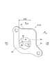
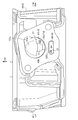
- FIG. 1 It is a left side side schematic view of the motorcycle 1 provided with the intake structure of the internal combustion engine which concerns on one Embodiment of this invention. It is a right cross-sectional side view along the cylinder axis C of the cylinder block, the cylinder head, the head cover and the periphery of the power unit in FIG. It is a perspective view of the upstream side of the reed valve body of a reed valve. It is a perspective view of the downstream side of the reed valve body of a reed valve. It is a perspective view of the downstream side of the reed valve body having the same orientation as FIG. 4, and shows the state in which the reed valve body is fastened to the reed valve body.
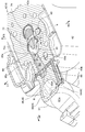
- FIG. 2 is a perspective view of a cross section substantially diagonally intersecting the cylinder axis C along the tumble passage of the cylinder head, as viewed from the head cover side, as viewed by VII-VII in FIG. It is a top perspective view of the cylinder head seen from the upper right rear view by arrow VIII in FIG.
- FIGS. 1 to 8 An intake structure of an internal combustion engine according to an embodiment of the present invention will be described with reference to FIGS. 1 to 8.
- the saddle-mounted vehicle is specifically a scooter-type motorcycle (hereinafter, simply referred to as "motorcycle").
- the arrow FR indicates the front of the vehicle
- LH indicates the left side of the vehicle
- RH indicates the right side of the vehicle
- UP indicates the upper part of the vehicle.
- FIG. 1 shows an outline of the left side surface of the motorcycle 1 provided with the intake structure of the internal combustion engine according to the present embodiment.
- the front portion 1A of the vehicle body and the rear portion 1B of the vehicle body are connected via a low floor portion 1C (footrest portion), and the vehicle body frame 2 forming the skeleton of the vehicle body is generally down. It consists of a frame 21 and a main frame 22. That is, the down frame 21 extends downward from the head pipe 20 of the front portion 1A of the vehicle body, and the lower frame portions 22a of the pair of left and right main frames 22 extending substantially horizontally from the lower end of the down frame 21 to the rear are connected.
- the main frame 22 extending diagonally rearward and upward from the rear end of the lower frame portion 22a forms a pair of left and right inclined portions 22b, and the upper portion of the inclined portion 22b is further bent and extends substantially horizontally to the rear. Is forming.
- a storage box (also called a helmet box) 11 is supported on the inclined portion 22b and the horizontal portion 22c of the main frame 22, and the passenger seat 12 is placed above the storage box (also called a helmet box).
- the handle 13 is pivotally supported by the head pipe 20 and the handle 13 is provided above, the front fork 14 extends downward, and the front wheel 15 is pivotally supported at the lower end thereof.
- a power unit support bracket 23 is projected rearward from the inclined portion 22b of the main frame 22, and a swing type power unit (hereinafter, simply referred to as “power unit”) 3 swings up and down on the power unit support bracket 23 via a link member 24.
- power unit swing type power unit
- the head pipe 20 and the down frame 21 are covered from the front and rear by the front cover 10a and the leg shield 10b of the vehicle body cover 10.
- the floor portion 1C is provided on the left and right pair of lower frame portions 22a side of the main frame 22 of the vehicle body frame 2, and the upper part of the lower frame portion 22a is covered by the floor cover 10c, and the left and right sides of the floor side cover are covered in the front-rear direction. It is covered with 10d and the lower part is covered with undercover 10e.
- a fuel tank 16 is provided in the horizontal portion 22c of the main frame 22 below the rear portion of the occupant seat 12 and above the rear wheels 17, and the inclined portion 22b and the horizontal portion 22c of the main frame 22 are body covers.
- the left and right and the rear are covered by 10f.
- a front fender 10 g is provided above the front wheel 15.
- Each of the covers 10a to 10g constituting the vehicle body cover 10 is formed of an appropriate material such as a resin material.
- the power unit 3 is provided with an internal combustion engine 4, and is provided with a power transmission unit 5 in which a belt-type continuously variable transmission 51 is internally provided from the internal combustion engine 4 to the rear.
- a reduction gear mechanism 52 transmitted from a belt-type continuously variable transmission 51 is provided at the rear of the power transmission unit 5, and a rear wheel 17 is provided on the rear axle 52a, which is an output shaft thereof.
- a rear cushion 18 is interposed between the rear portion of the power transmission portion 5 and the horizontal portion 22c at the rear portion of the main frame 22.
- the internal combustion engine 4 is a single-cylinder air-cooled 4-stroke cycle internal combustion engine that rotatably supports the crankcase 30 by directing the crankshaft 41 in the vehicle width direction, that is, in the left-right direction, and projects from the front portion of the crankcase 30.
- the cylinder block 42, the cylinder head 43, and the head cover 44 are sequentially overlapped with each other, and the cylinder axis C is fastened so as to be substantially horizontal and tilted forward.
- An inlet manifold 61 and a throttle body 62 are provided above the power unit 3 and above the cylinder head 43 to the crankcase 30, and an inlet manifold 61 is provided at the intake port inlet 45a above the cylinder head 43 that is tilted forward.
- the inlet manifold 61 is connected to the throttle body 62 by bending backward on the upstream side and extending.
- An air cleaner 64 attached to the upper part of the power transmission unit 5 is connected to the upstream side of the throttle body 62 via a connecting tube 63.
- An intake passage 6 is formed from the connecting tube 63 through the throttle body 62, the inlet manifold 61, and the intake port 45 of the cylinder head 43, and leads to the combustion chamber 32.
- the upstream exhaust pipe 48a connected to the exhaust port outlet 47a at the lower part of the cylinder head 43 is interposed with a substantially cylindrical catalyst device 49 oriented in the vehicle width direction, and purifies the exhaust gas inside the catalyst device 49.
- a catalyst such as a three-way catalyst is loaded.
- the downstream exhaust pipe 49b connected to the outlet of the catalyst device 49 bends rearward and extends rearward along the right side of the vehicle, and is connected to a muffler (not shown) on the right side of the rear wheel 17.
- FIG. 2 is a right sectional side view of the cylinder block 42, the cylinder head 43, the head cover 44, and the periphery thereof of the power unit 3 in FIG. 1 along the cylinder axis C.
- the crankcase 30 is composed of a left-right case half body 30L divided into left and right and a right case half body (not shown), and the left case half body 30L is extended rearward to extend the crankshaft 41 and rear.
- a power transmission unit 5 is formed in front of and behind the rear axle 52a of the wheel 17 to accommodate a transmission device including a long belt-type stepless transmission 51 (not shown) and a reduction gear mechanism 52 and the like.
- the piston 33 that reciprocates in the cylinder bore 42a of the cylinder block 42 is connected to the crankpin 41a of the crankshaft 41 of the crankcase 30 by a connecting rod 34.
- a combustion chamber 32 is formed between the top surface 33a of the piston 33 slidably fitted in the cylinder bore 42a of the cylinder block 42 and the combustion chamber ceiling surface 43a of the cylinder head 43 facing the top surface 33a.
- the throttle body 62 is fastened and connected to the inlet manifold 61 connected to the intake port inlet 45 of the cylinder head 43 in the present embodiment via a reed valve 8 described later on the upstream side. ..
- a throttle valve 62a is incorporated in the intake passage 6 and rotates around the throttle valve shaft 62b to open and close the intake passage 6 and adjust the intake flow rate.
- reference numeral 31 denotes a bracket portion that is projected upward from the upper part of the crankcase 30 and for suspending the power unit 3 on the vehicle body frame 2.
- a bracket portion 31 is pivotally supported by a power unit support bracket 23 projecting rearward from an inclined portion 22b of the main frame 22 via a link member 24, and the power unit 3 is a vehicle body. It swings up and down with respect to the frame 2.
- the rear end of the power unit 3 that swings up and down is supported by the rear cushion 18 on the horizontal portion 22c of the main frame 22.
- an inlet manifold 61 is connected to the front of the throttle body 62, that is, on the downstream side of the intake air, bends downward, and is connected to the intake port inlet 45a above the cylinder head 43 with the insulator 60 sandwiched between them. doing.
- a fuel injection valve 39 is attached to the downstream end of the inlet manifold 61, and fuel is injected toward the intake valve port 35. Since the fuel injection has a certain spread with respect to the injection center line I shown in FIG. 2, the fuel injection avoidance recess 67a for avoiding the injected fuel is provided in the main passage head inlet opening 67 on the downstream side, which will be described later. (See FIG. 6).
- a fuel hose (not shown) connected to the fuel injection valve 39 is arranged rearward and is connected to a fuel tank 16 provided above the rear wheels 17 via a fuel pump device (not shown).
- the internal combustion engine 4 employs a single-cylinder SOHC type two-valve system, and the cylinder head 43 is provided with a valve operating mechanism 9.
- a head cover 44 is overlapped and covered on the cylinder head 43 so as to cover the valve operating mechanism 9.
- an endless cam chain (not shown) is provided on one side of the crankcase 30, the cylinder block 42, and the cylinder head 43 in the crankshaft 41 direction. It is erected between the cam shaft 91 and the crank shaft 41 through the chain chamber, and the cam shaft 91 rotates at a rotation speed of 1/2 in synchronization with the crank shaft 41.
- a spark plug 40 (see FIG. 4) is fitted in the cylinder head 43 from the side opposite to the cam chain chamber (the other side in the direction of the crankshaft 41) toward the inside of the combustion chamber 32.
- the intake port 37 and the exhaust port 38 are separated from each other vertically from the intake valve port 35 and the exhaust valve port 36 opened in the combustion chamber ceiling surface 43a, respectively. It is formed by extending while curving in the direction.
- the upstream end of the intake port 37 opens upward toward the cylinder head 43 to form an intake port inlet 45, which is connected to the inlet manifold 61 to form a continuous intake passage 6 on the upstream side of the inlet manifold 61.
- Throttle body 62 is connected.
- the downstream end of the exhaust port 38 forms the exhaust port outlet 47, opens downward of the cylinder head 43, and is connected to the upstream exhaust pipe 48a (see FIG. 1).
- a cylindrical intake valve guide 71 is integrally fitted to the curved outer wall portion 37a of the intake port 37 in the cylinder head 43, and the intake valve 73 slidably supported by the intake valve guide 71 is a combustion chamber of the intake port 37. Open and close the intake valve port 35 facing 32. Further, the exhaust valve 74 slidably supported by the exhaust valve guide 72 integrally fitted to the curved outer wall portion 38a of the exhaust port 38 in the cylinder head 43 faces the combustion chamber 32 of the exhaust port 38. Open and close 36.
- the intake valve 73 and the exhaust valve 74 are urged upward by the valve spring 75 so that the umbrella portions 73a and 74a both close the intake valve port 35 and the exhaust valve port 36 facing the combustion chamber 32.
- the intake cam of the cam shaft 90, the intake rocker arm 91 that swings in contact with the exhaust cam, and the exhaust rocker arm 92 push down the stem ends 73b and 74b of the intake valve 73 and the exhaust valve 74, and the intake valve 73,
- the exhaust valve 74 opens, and the intake port 37 and the combustion chamber 32 communicate with each other, and the exhaust port 38 and the combustion chamber 32 communicate with each other to perform intake and exhaust at predetermined timings.
- a vertical rotating vortex of the fuel / air mixture (rotating vortex on a virtual plane along the cylinder axis C) in the combustion chamber 32. )
- a tumble flow T and a lateral rotating vortex (a rotating vortex on a virtual plane orthogonal to the cylinder axis C), that is, an intake structure for giving a swirl flow S
- An inlet manifold 61 is connected to the upstream end of the intake port 37 of the internal combustion engine 4 via an insulator 60 to form a continuous intake passage 6, and a reed valve 8 described later is located upstream of the inlet manifold 61.
- the throttle body 62 is connected via.
- the throttle body 62 has an intake passage 62c having a substantially circular cross section forming a part of an intake passage 6 connected to a combustion chamber 32 of the internal combustion engine 4, and an air cleaner 64 (FIG. 1) is connected.
- the throttle body 62 is rotatably supported in the throttle body 62 by a throttle valve shaft 62b oriented perpendicularly to the intake flow direction F of the intake passage 62c, that is, perpendicular to the central axis X of the intake passage 62c and substantially horizontally. It is provided with a single butterfly type throttle valve 62a that can variably control the flow path area of the intake passage 62c and open and close the intake passage 62c.
- the throttle valve 62a can be rotated clockwise in the drawing of FIG. 2 in the valve opening direction by an operation of the driver or the like, and is urged clockwise in the valve closing direction by a return spring (not shown).
- the intake passage 62c of the throttle body 62 is oriented substantially horizontally.
- the intake passage 6 is continuously divided into upper and lower parts along the intake flow direction by the partition wall 65 from the inlet manifold 61 to the intake port 37, and the passing intake air passes through the tumble flow T in the combustion chamber 32. It is divided into a tumble passage 6A on the lower side in the drawing and a main passage 6B on the upper side in the drawing excluding the tumble passage 6A which are configured to generate.
- the "tumble passage” is an intake passage for generating a tumble flow T in the combustion chamber 32 when the throttle valve 62a has a low opening degree, that is, when the load of the internal combustion engine 4 is low.
- the vertical arrangement of the tumble passage 6A and the main passage 6B is not limited to that of the embodiment.
- the partition wall 65 is configured such that the inlet manifold side partition wall 65A, the insulator side partition wall 65B, and the intake port side partition wall 65C are continuously positioned from the upstream side to the downstream side of the intake air flow.
- the main passage 6B on the upper side of the drawing and the tumble passage 6A on the lower side of the drawing divide the intake passage 6 on the downstream side of the throttle body 62 into the upper and lower parts of the drawing by a vertical partition wall 65 from the inlet manifold 61 to the intake port 37.
- a lead valve 8 formed in a substantially triangular shape in the side view cross section of the intake passage 6 is interposed between the throttle body 62 and the inlet manifold 61. Has been done.
- FIG. 3 is a perspective view of the upstream side of the reed valve body 81 of the reed valve 8, and the intake passage 6 is opened in the mounting flange portion 85, and the main passage side is behind the valve intake passage 80 inside the intake passage 6.
- the exit opening 86 and the exit opening 84 on the tumble passage side can be seen.
- FIG. 4 is a perspective view of the reed valve body 81 of the reed valve 8 on the downstream side. The back portion of the mounting flange portion 85, the main passage side outlet opening 86 of the inclined surface 81a, and the tumble passage side of the downstream end portion 83.
- the exit opening 84 and the like are shown.
- FIG. 5 is a perspective view of the downstream side of the reed valve 8 having the same orientation as that of FIG. 4, showing a state in which the reed valve body 87 is fastened to the reed valve body 81.
- the reed valve 8 includes a reed valve body 81 that forms the whole, and a mounting flange portion 85 thereof is sandwiched and fastened between a downstream end portion of the throttle body 62 and an upstream end portion of the inlet manifold 61.
- An inlet opening 82 that matches the downstream opening 62d of the throttle body 62 is provided on the surface of the reed valve body 81 that is attached to the throttle body 62, and a valve that communicates with the intake passage 62c of the throttle body 62 inside the reed valve body 81.
- the intake passage 80 is formed.
- the downstream end 83 of the reed valve body 81 is formed with a tumble passage side outlet opening 84 that abuts on the upstream end 65Aa of the inlet manifold side partition wall 65A and matches the upstream end opening 6Aa of the tumble passage 6A of the inlet manifold 61. Will be done.
- the upper portion of the reed valve body 81 is formed so as to be inclined from the back portion of the mounting flange portion 85 to the lower portion on the downstream side of the reed valve 8.
- the main passage side outlet opening 86 that communicates the 80 with the main passage 6B of the inlet manifold 61 is formed.
- a lead valve body 87 is fastened to the outer surface of the main passage side outlet opening 86 so as to cover the main passage side outlet opening 86, and one end portion 87a on the upstream side is fastened to the back portion of the flange portion 85 by a lead valve body screw 87c. ..
- the opening side edge 87b on the other end side of the reed valve body 87 is a swing free end, and comes into contact with the reed valve body 81 above the tumble passage side outlet opening 84 of the downstream end portion 83 of the reed valve body 81.
- the main passage side outlet opening 86 is kept closed, and the inlet manifold 61 is tumbled exclusively from the valve intake passage 80 in the reed valve body 81.
- the intake air flows into the passage 6A.
- the opening side edge portion 87b on the downstream side of the reed valve body 87 Bends to open the outlet opening 86 on the main passage side, and the intake air flows from the valve intake passage 80 in the reed valve body 81 to the main passage 6B of the inlet manifold 61.
- the upstream end opening 6Aa of the tumble passage 6A of the intake passage 6 of the inlet manifold 61 connected to the downstream side of the valve intake passage 80 of the reed valve 8 is the tumble passage side outlet opening 84 of the downstream end 83 of the reed valve 8.
- the upstream end opening 6Ba of the main passage 6B is connected to the downstream side of the main passage side outlet opening 86 of the inclined surface 81a of the reed valve 8 and is opened.
- the throttle valve 62a is provided near the downstream end of the intake passage 70 of the throttle body 62, and the reed valve 8 has a tumble passage side outlet opening 84 and a main passage side outlet. Since the opening 86 is connected via the valve intake passage 80 having a suppressed volume, the response of the reed valve body 87 of the main passage side outlet opening 86 to the state of the throttle valve 62a is quick, and the tumble passage 6A and the main passage The response of 6B intake flow switching is high.
- the reed valve 8 is provided between the throttle body 62 and the inlet manifold 61, and the tumble passage side outlet opening 84 has a cross section below the intake passage 6 as shown in FIGS. 4 and 5. 69 is horizontally long and wide, and the opening cross section is large.
- the reed valve body 87 that limits the intake flow of the main passage 6B covers the main passage side outlet opening 86 of the reed valve 8 and has one end portion 87a on the upstream side attached to the reed valve body 81 and an opening side edge portion on the downstream side. 87b is formed in a direction parallel to the passage width direction of the tumble passage 6A.
- the main passage side outlet opening 86 of the reed valve 8 can be provided large. It is possible to reduce the flow path resistance of both the main passage 6B and the tumble passage 6A to improve the intake efficiency.
- the reed valve body 81 of the reed valve 8 is integrally molded by a molding die, and the main passage 6B in the reed valve body 81 is molded by a molding die combined from the downstream side.
- the tumble passage 6A in 81 is formed by a mold that is combined from the upstream side, and is formed by a mold that is combined from two directions with each other. Therefore, as shown in FIG. 2, the main passage 9B in the reed valve 8 is formed at an angle ⁇ that spreads toward the downstream side due to the draft of the molding die.
- the tumble passage 6A in the reed valve 8 is formed at an angle ⁇ that narrows toward the downstream side due to the draft of the molding die.
- the passage area of the main passage 6B increases from the entrance to the exit, while the tumble passage 6A is reduced in reverse, so that both passages 6A and 6B
- the change in the total passage area is reduced, the turbulence of the intake flow flow velocity during high-load operation can be prevented, and the engine performance is improved.
- a fuel injection valve 39 is attached to the inlet manifold 61 so as to penetrate the main passage 6B from above and outside and inject and supply fuel toward the intake valve port 35.
- the fuel injection valve 39 is arranged in the inlet manifold 61, but a direct injection structure in which the fuel injection valve 39 is arranged in the cylinder head 43 or the cylinder block 42 and fuel is injected into the combustion chamber 32 is also available. good.
- the tumble passage side outlet opening 84 of the downstream end 83 of the reed valve 8 is formed in a horizontally long oval cross section that is long in the passage width direction. Therefore, the tumble passage 6A of the inlet manifold 61 connected to the outlet opening 84 on the tumble passage side is also formed by partitioning the intake passage 6 by the partition wall 65A on the inlet manifold side, and the cross section 69 is horizontally long in the passage width direction. It is formed in the horizontally long cross section of the oval shape.
- the main passage side outlet opening width 86W of the main passage side outlet opening 86 of the reed valve body 81 shown in FIG. 4 is formed wider than the inlet opening width 82W of the inlet opening 82 of the reed valve body 81 shown in FIG. Has been done. Therefore, the intake air flow of the internal combustion engine 4 when the load is high can be smoothly flowed to the main passage 6B side, and the engine performance can be improved.
- the tumble passage side outlet opening 84 is a stepped portion 88 provided on both lower sides of the main passage side outlet opening 86. It is provided vertically adjacent to the main passage side outlet opening 86 and narrower than the main passage side outlet opening 86 below the narrowed portion. Therefore, the tumble passage side outlet opening 84 is narrowed by the step portion 88, the flow velocity of the tumble passage 6A is increased when the load of the internal combustion engine 4 is low, lean combustion is improved, and fuel efficiency is improved.
- the reed valve body 87 of the reed valve 8 that closes in the intake flow during the low load operation of the internal combustion engine 4 is provided in the main passage 6B of the intake passage 6, the internal combustion engine 4 is low.
- the reed valve body 87 of the reed valve 8 can limit the intake air flowing through the main passage 6B, and the intake air flow can mainly flow to the tumble passage 6A, so that the tumble flow T in the combustion chamber 32 can be further increased.
- the tumble flow T shown by the alternate long and short dash line in FIG. 2 schematically shows the tumble flow T in the combustion chamber 32 when the piston 33 descends in the cylinder bore 42a as shown by the alternate long and short dash line. ..
- FIG. 6 is a top view of the cylinder head 43 viewed from the arrow VI-VI in FIG. 2, and the intake port inlet 45 is shown on the intake side flange surface 43b to which the inlet manifold 61 is fastened via the insulator 60.
- the intake port inlet 45 is partitioned by the intake port side partition wall 65C, and the tumble passage head inlet opening 66 and the main passage head inlet opening 67 are opened.
- the tumble passage head inlet opening 66 is also the tumble passage 6A of the inlet manifold 61.
- it is formed in a horizontally long cross section 69 having a horizontally long oval shape that is long in the passage width direction.
- the main passage head inlet opening 67 is formed with a fuel injection avoiding recess 67a for avoiding fuel injected from the fuel injection valve 39 (see FIG. 2).
- the tumble passage 6A of the cylinder head 43 is formed by casting when the cylinder head 43 is cast, but it may be formed by machining after the cylinder head 43 is formed. However, as described above, the tumble passage 6A is preferably formed at the time of casting because the cross section 69 is formed in a horizontally long oval-shaped horizontally long cross section that is long in the passage width direction. As shown in FIG. 2, the tumble passage 6A of the cylinder head 43 is formed so that the passage cross-sectional height h is uniform from the tumble passage head inlet opening 66 to the tumble passage outlet 68.
- the orientation of the tumble passage 6A of the cylinder head 43 and the passage cross-sectional height h are such that the intake flow f that has passed through the tumble passage 6A of the cylinder head 43 and is ejected into the intake port 37 is shown by a chain double-dashed line in FIG. , It is set to face between the umbrella portion 73a of the opened intake valve 73 and the intake valve valve seat 77.
- an intake valve guide 71 fitted to the curved outer wall portion 37a of the intake port 37 and an intake valve 73 slidably supported by the intake valve guide 71 are provided behind the main passage head inlet opening 67. The shaft of is shown.
- the cross section 69 of the tumble passage 6A formed by the partition wall 65 in the intake passage 6 is formed in a horizontally long oval cross section long in the passage width direction, so that the internal combustion engine 4 can be operated at a low load.
- the intake air flow at the time is rectified along the tumble passage 6A, the collision interference with the intake valve seat 77 of the intake valve port 35 is reduced and flows into the combustion chamber 32, and the tumble flow T is strengthened, so that the load is low. Atomization of the air-fuel mixture by the tumble flow T during operation is promoted, rapid combustion and lean combustion are possible, and fuel efficiency can be improved.
- FIG. 7 is a perspective view of a cross section substantially diagonally intersecting the cylinder axis C along the tumble passage 6A of the cylinder head 43, as viewed from the head cover 44 side, as viewed by VII-VII in FIG. ..
- one end 69a in the longitudinal direction of the cross section 69 of the tumble passage 6A is oriented along the tangential direction of the opening edge 35a of the intake valve port 35, and the other end 69b is directed to the intake valve port 35. It is oriented so that the width w in the longitudinal direction of the cross section 69 is gradually narrowed.
- the intake flow flowing through the tumble passage 6A can flow linearly into the combustion chamber 32 through the intake valve port 35, and the longitudinal width w of the cross section 69 of the tumble passage 6A is gradually narrowed. Therefore, the cross-sectional area of the passage is gradually reduced and the flow velocity is gradually increased, so that the tumble flow T is strengthened in the combustion chamber 32, the atomization of the air-fuel mixture is further promoted, and leaner combustion is possible, which enables fuel efficiency. Can be improved.
- a pair of intake valves 73 and exhaust valves 74 are oriented above the combustion chamber 32 by opening the shaft portions 73c and the shaft portions 74c in a V shape in the front-rear direction. Being prepared.
- a virtual extension line b in the passage direction of the other end 69b of the tumble passage 6A passes near the shaft portion 73c of the intake valve 73, and the combustion chamber on the other end 69b side. Spark plugs 40 are arranged around 32.
- the intake air flowing out from the other end 69b side of the tumble passage 6A flows so as to be in contact with the shaft portion 73c of the intake valve 73, so that the upper surface of the umbrella portion 73a of the intake valve 73 and the intake valve valve of the intake valve port 35
- the intake flow on the other end 69b side that directly flows in through the port opening 78 between the seat 77 and the seat 77 comes into contact with the shaft portion 73c to reduce the flow velocity, and a swirl flow S toward the other end 69b side is generated. Therefore, the tumble flow T is inclined in the swirl flow S direction to guide the air-fuel mixture to the spark plug 40 provided on the other end 69b side of the tumble passage 6A, and the ignitability of the spark plug 40 is enhanced.
- the swirl flow S shown by the alternate long and short dash line in FIG. 7 schematically represents the swirl flow S in the combustion chamber 32 when the piston 33 descends in the cylinder bore 42a as shown by the alternate long and short dash line in FIG. It shows.
- the tumble passage 80A is a side view with respect to a cross section along the cylinder axis C, and is an umbrella portion 73a when the intake valve 73 is opened and an exhaust valve port of the intake valve port 35. It is formed in a straight line facing the intake valve valve seat 77 on the 36 side. Therefore, as shown by the alternate long and short dash line in FIG. 2, the intake flow f flowing out of the tumble passage 6A is passed above the umbrella portion 73a of the intake valve 73, and collision interference with the intake valve seat 77 is reduced. Since it can be directly flowed into the cylinder bore 42a, the tumble flow T is likely to occur in the combustion chamber 32.
- FIG. 8 is a perspective view of the upper surface of the cylinder head 43 as viewed from the upper right rear side as viewed from the upper right rear view of FIG. 2 in FIG. It is shown from the right side that the spark plug 40 is attached.
- the upper surface 61a of the inlet manifold 61 is a reed valve body of the main passage 6B of the inserted reed valve 8. Since 87 forms a substantially rectangular shape wide in the width direction of the passage and moves up and down upward, it is formed in a plane so as to match it (see also FIG. 2). Therefore, the upper part of the inlet manifold 61 is made compact, and the space for other equipment, piping, etc. is increased.
Landscapes
- Engineering & Computer Science (AREA)
- Chemical & Material Sciences (AREA)
- Combustion & Propulsion (AREA)
- Mechanical Engineering (AREA)
- General Engineering & Computer Science (AREA)
- Cylinder Crankcases Of Internal Combustion Engines (AREA)
Priority Applications (4)
| Application Number | Priority Date | Filing Date | Title |
|---|---|---|---|
| EP20925010.9A EP4123139B1 (en) | 2020-03-16 | 2020-03-16 | Internal combustion engine with intake structure |
| BR112022016122A BR112022016122A2 (pt) | 2020-03-16 | 2020-03-16 | Estrutura de admissão para motor de combustão interna |
| PCT/JP2020/011549 WO2021186513A1 (ja) | 2020-03-16 | 2020-03-16 | 内燃機関の吸気構造 |
| JP2022508627A JP7336587B2 (ja) | 2020-03-16 | 2020-03-16 | 内燃機関の吸気構造 |
Applications Claiming Priority (1)
| Application Number | Priority Date | Filing Date | Title |
|---|---|---|---|
| PCT/JP2020/011549 WO2021186513A1 (ja) | 2020-03-16 | 2020-03-16 | 内燃機関の吸気構造 |
Publications (1)
| Publication Number | Publication Date |
|---|---|
| WO2021186513A1 true WO2021186513A1 (ja) | 2021-09-23 |
Family
ID=77770747
Family Applications (1)
| Application Number | Title | Priority Date | Filing Date |
|---|---|---|---|
| PCT/JP2020/011549 Ceased WO2021186513A1 (ja) | 2020-03-16 | 2020-03-16 | 内燃機関の吸気構造 |
Country Status (4)
| Country | Link |
|---|---|
| EP (1) | EP4123139B1 (https=) |
| JP (1) | JP7336587B2 (https=) |
| BR (1) | BR112022016122A2 (https=) |
| WO (1) | WO2021186513A1 (https=) |
Cited By (2)
| Publication number | Priority date | Publication date | Assignee | Title |
|---|---|---|---|---|
| WO2024202016A1 (ja) * | 2023-03-31 | 2024-10-03 | 本田技研工業株式会社 | 内燃機関の吸気構造 |
| JP2025151090A (ja) * | 2024-03-27 | 2025-10-09 | 本田技研工業株式会社 | 内燃機関 |
Citations (4)
| Publication number | Priority date | Publication date | Assignee | Title |
|---|---|---|---|---|
| JPH10231729A (ja) * | 1997-02-17 | 1998-09-02 | Nissan Motor Co Ltd | 内燃機関の吸気装置 |
| WO1999067514A1 (en) * | 1998-06-22 | 1999-12-29 | Hitachi, Ltd. | Cylinder-injection type internal combustion engine, method of controlling the engine, and fuel injection nozzle |
| JP2016061279A (ja) * | 2014-09-22 | 2016-04-25 | 本田技研工業株式会社 | 内燃機関の吸気構造 |
| WO2019009347A1 (ja) | 2017-07-05 | 2019-01-10 | 本田技研工業株式会社 | シリンダヘッド |
Family Cites Families (5)
| Publication number | Priority date | Publication date | Assignee | Title |
|---|---|---|---|---|
| JP4044195B2 (ja) * | 1998-01-30 | 2008-02-06 | ヤマハ発動機株式会社 | エンジンの吸気装置 |
| JP2001159314A (ja) | 1999-12-01 | 2001-06-12 | Nissan Motor Co Ltd | 内燃機関の燃焼室構造 |
| EP3428433B1 (en) * | 2016-03-09 | 2020-02-19 | Honda Motor Co., Ltd. | Internal combustion engine intake structure |
| EP3650671B1 (en) | 2017-07-05 | 2021-03-31 | Honda Motor Co., Ltd. | Internal combustion engine intake structure |
| JP6691564B2 (ja) | 2018-03-15 | 2020-04-28 | 本田技研工業株式会社 | 内燃機関の吸気通路 |
-
2020
- 2020-03-16 WO PCT/JP2020/011549 patent/WO2021186513A1/ja not_active Ceased
- 2020-03-16 JP JP2022508627A patent/JP7336587B2/ja active Active
- 2020-03-16 EP EP20925010.9A patent/EP4123139B1/en active Active
- 2020-03-16 BR BR112022016122A patent/BR112022016122A2/pt not_active Application Discontinuation
Patent Citations (5)
| Publication number | Priority date | Publication date | Assignee | Title |
|---|---|---|---|---|
| JPH10231729A (ja) * | 1997-02-17 | 1998-09-02 | Nissan Motor Co Ltd | 内燃機関の吸気装置 |
| WO1999067514A1 (en) * | 1998-06-22 | 1999-12-29 | Hitachi, Ltd. | Cylinder-injection type internal combustion engine, method of controlling the engine, and fuel injection nozzle |
| JP2016061279A (ja) * | 2014-09-22 | 2016-04-25 | 本田技研工業株式会社 | 内燃機関の吸気構造 |
| JP6268604B2 (ja) | 2014-09-22 | 2018-01-31 | 本田技研工業株式会社 | 内燃機関の吸気構造 |
| WO2019009347A1 (ja) | 2017-07-05 | 2019-01-10 | 本田技研工業株式会社 | シリンダヘッド |
Cited By (2)
| Publication number | Priority date | Publication date | Assignee | Title |
|---|---|---|---|---|
| WO2024202016A1 (ja) * | 2023-03-31 | 2024-10-03 | 本田技研工業株式会社 | 内燃機関の吸気構造 |
| JP2025151090A (ja) * | 2024-03-27 | 2025-10-09 | 本田技研工業株式会社 | 内燃機関 |
Also Published As
| Publication number | Publication date |
|---|---|
| EP4123139A1 (en) | 2023-01-25 |
| JPWO2021186513A1 (https=) | 2021-09-23 |
| BR112022016122A2 (pt) | 2022-10-04 |
| EP4123139A4 (en) | 2023-07-26 |
| EP4123139B1 (en) | 2024-09-18 |
| JP7336587B2 (ja) | 2023-08-31 |
Similar Documents
| Publication | Publication Date | Title |
|---|---|---|
| US20190085744A1 (en) | Exhaust device for internal combustion engine | |
| EP3594471B1 (en) | Air intake structure for internal combustion engine | |
| CN104114832A (zh) | 内燃机的吸气装置 | |
| JP3153075U (ja) | 車両用エンジンユニットおよび鞍乗り型車両 | |
| CN108779736B (zh) | 内燃机的进气构造 | |
| WO2021186513A1 (ja) | 内燃機関の吸気構造 | |
| JP6262587B2 (ja) | 内燃機関の吸気構造 | |
| JPWO2019009347A1 (ja) | シリンダヘッド | |
| US7156066B2 (en) | Air intake device for engine | |
| JP5711584B2 (ja) | 内燃機関 | |
| JP6215807B2 (ja) | 内燃機関の吸気装置 | |
| EP3650671B1 (en) | Internal combustion engine intake structure | |
| JP6748782B2 (ja) | 内燃機関の吸気構造 | |
| WO2024202016A1 (ja) | 内燃機関の吸気構造 | |
| WO2022208699A1 (ja) | 内燃機関の吸気構造 | |
| JP7850757B2 (ja) | 内燃機関の吸気構造 | |
| WO2021192927A1 (ja) | 鞍乗型車両用内燃機関の吸気装置 | |
| CN111608817B (zh) | 鞍乘型车辆用内燃机 | |
| JP7600425B2 (ja) | 内燃機関の吸気装置 | |
| JP2025151090A (ja) | 内燃機関 | |
| JP2020148184A (ja) | エアクリーナ内のファンネル構造 | |
| WO2022209880A1 (ja) | 内燃機関の吸気装置 | |
| JP2015113822A (ja) | エンジンの吸気装置 | |
| JP2024132251A (ja) | 圧力調整構造及び鞍乗型車両 | |
| JP6186299B2 (ja) | 鞍乗り型車両の吸気構造 |
Legal Events
| Date | Code | Title | Description |
|---|---|---|---|
| 121 | Ep: the epo has been informed by wipo that ep was designated in this application |
Ref document number: 20925010 Country of ref document: EP Kind code of ref document: A1 |
|
| ENP | Entry into the national phase |
Ref document number: 2022508627 Country of ref document: JP Kind code of ref document: A |
|
| REG | Reference to national code |
Ref country code: BR Ref legal event code: B01A Ref document number: 112022016122 Country of ref document: BR |
|
| WWE | Wipo information: entry into national phase |
Ref document number: 202217050867 Country of ref document: IN |
|
| ENP | Entry into the national phase |
Ref document number: 112022016122 Country of ref document: BR Kind code of ref document: A2 Effective date: 20220812 |
|
| NENP | Non-entry into the national phase |
Ref country code: DE |
|
| ENP | Entry into the national phase |
Ref document number: 2020925010 Country of ref document: EP Effective date: 20221017 |