WO2021186498A1 - 空気調和機 - Google Patents
空気調和機 Download PDFInfo
- Publication number
- WO2021186498A1 WO2021186498A1 PCT/JP2020/011442 JP2020011442W WO2021186498A1 WO 2021186498 A1 WO2021186498 A1 WO 2021186498A1 JP 2020011442 W JP2020011442 W JP 2020011442W WO 2021186498 A1 WO2021186498 A1 WO 2021186498A1
- Authority
- WO
- WIPO (PCT)
- Prior art keywords
- auto
- control unit
- air conditioner
- temperature
- room temperature
- Prior art date
- Legal status (The legal status is an assumption and is not a legal conclusion. Google has not performed a legal analysis and makes no representation as to the accuracy of the status listed.)
- Ceased
Links
Images







Classifications
-
- F—MECHANICAL ENGINEERING; LIGHTING; HEATING; WEAPONS; BLASTING
- F24—HEATING; RANGES; VENTILATING
- F24F—AIR-CONDITIONING; AIR-HUMIDIFICATION; VENTILATION; USE OF AIR CURRENTS FOR SCREENING
- F24F11/00—Control or safety arrangements
- F24F11/30—Control or safety arrangements for purposes related to the operation of the system, e.g. for safety or monitoring
- F24F11/49—Control or safety arrangements for purposes related to the operation of the system, e.g. for safety or monitoring ensuring correct operation, e.g. by trial operation or configuration checks
-
- F—MECHANICAL ENGINEERING; LIGHTING; HEATING; WEAPONS; BLASTING
- F24—HEATING; RANGES; VENTILATING
- F24F—AIR-CONDITIONING; AIR-HUMIDIFICATION; VENTILATION; USE OF AIR CURRENTS FOR SCREENING
- F24F11/00—Control or safety arrangements
- F24F11/62—Control or safety arrangements characterised by the type of control or by internal processing, e.g. using fuzzy logic, adaptive control or estimation of values
- F24F11/63—Electronic processing
- F24F11/65—Electronic processing for selecting an operating mode
-
- F—MECHANICAL ENGINEERING; LIGHTING; HEATING; WEAPONS; BLASTING
- F24—HEATING; RANGES; VENTILATING
- F24F—AIR-CONDITIONING; AIR-HUMIDIFICATION; VENTILATION; USE OF AIR CURRENTS FOR SCREENING
- F24F2110/00—Control inputs relating to air properties
- F24F2110/10—Temperature
-
- F—MECHANICAL ENGINEERING; LIGHTING; HEATING; WEAPONS; BLASTING
- F24—HEATING; RANGES; VENTILATING
- F24F—AIR-CONDITIONING; AIR-HUMIDIFICATION; VENTILATION; USE OF AIR CURRENTS FOR SCREENING
- F24F2120/00—Control inputs relating to users or occupants
- F24F2120/10—Occupancy
Definitions
- the present invention relates to an air conditioner.
- the air conditioner has a function (auto-off function) to switch the air conditioner to save operation or stop the operation of the air conditioner when there is no user in the room.
- the set temperature of the remote controller is subtracted by a predetermined value (during heating operation) or added by a predetermined value (during cooling operation), and the room temperature is controlled by this changed value.
- Patent Document 1 describes an air conditioner that detects a human body with a focused infrared sensor, even when the temperature difference between the room temperature and the user is small and it is difficult to detect the detected object.
- a method has been proposed in which the detection probability of the body can be increased, the probability of switching to a control different from the setting of the air conditioner is reduced, and the user or the like is not discomforted by erroneous control.
- the human body is not detected for a predetermined time and the room temperature is between 34 ° C. and 38 ° C., which is close to the temperature of the human body, the time until switching to an operation different from the set value is set to a predetermined value, and when the room temperature is out of the range, the predetermined value is set. This is a method of setting a value smaller than.
- Patent Document 1 it is proposed to set the time until switching to the save operation or the time until the operation is stopped to a predetermined value, but even at the predetermined value, in addition to the room temperature, the floor plan, the arrangement of furniture, etc. There is a possibility that the human body cannot be detected. Therefore, even if a human body exists in the air-conditioned space, there is a problem that the operation is automatically stopped (auto-off) due to unintended control by the user.
- the present invention is an invention for solving the above-mentioned problems, and an object of the present invention is to provide an air conditioner capable of maintaining indoor comfort when an auto-off function is set.
- the air conditioner of the present invention uses a room temperature detecting means (for example, a room temperature sensor 51) for detecting a room temperature, a human detection sensor for detecting a human body in a room, and a human detection sensor for a predetermined time.
- a room temperature detecting means for example, a room temperature sensor 51
- a human detection sensor for detecting a human body in a room
- a human detection sensor for a predetermined time.
- a control unit having an auto-off function for stopping the operation when the operation cannot be detected is provided, and the control unit is out of the predetermined auto-off permission range when the room temperature is out of the predetermined auto-off permission range while the auto-off function is enabled.
- the auto-off function is disabled.
- indoor comfort can be maintained when the auto-off function is set.
- FIG. 1 is an explanatory diagram showing an external configuration of an air conditioner according to the present embodiment.
- the air conditioner A is a device that performs indoor air conditioning such as cooling by using, for example, heat pump technology.
- the air conditioner A is roughly divided into an indoor unit 100 installed on an indoor wall, ceiling, floor, etc., an outdoor unit 200 installed outdoors, and communicates with the indoor unit 100 by infrared rays, radio waves, communication lines, or the like.
- a remote controller 40 remote controller, air conditioning control terminal
- various sensor units for obtaining information used for controlling and displaying the air conditioner such as room temperature and outside temperature. It consists of 50 (see FIG. 5).
- the indoor unit 100 and the outdoor unit 200 are connected to a refrigerant pipe by a communication cable (not shown).
- the indoor unit 100 has an infrared sensor 110 as one sensor of the sensor unit 50.
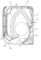
- FIG. 2 is an explanatory diagram showing a configuration of an indoor unit of the air conditioner according to the present embodiment.
- the indoor unit 100 includes a heat exchanger 102, a blower fan 103, a left and right wind direction plate 104 (wind direction portion), a vertical wind direction plate 105 (wind direction portion), a front panel 106, a housing base 101, and various sensor portions 50 (see FIG. 5). ) Etc.
- the heat exchanger 102 has a plurality of heat transfer tubes 102a, and heats the indoor air taken into the indoor unit 100 by the blower fan 103 with the refrigerant flowing through the heat transfer tubes 102a to cool the air. Or it is configured to heat.
- the heat transfer tube 102a is connected to the above-mentioned refrigerant pipe and constitutes a part of a known refrigerant cycle.
- the blower fan 103 can adjust the wind speed.
- the left and right wind direction plates 104 are rotated in the forward and reverse directions by the left and right wind direction plate motors with the rotation shaft provided at the lower part of the indoor unit as a fulcrum on the base end side thereof.
- the tip side of the left and right wind direction plate 104 faces the indoor side, so that the tip side of the left and right wind direction plate 104 can operate so as to swing in the horizontal direction.
- the vertical wind direction plate 105 is rotated in the forward and reverse directions by the motor for the vertical wind direction plate with the rotation shafts provided at both ends of the indoor unit 100 in the longitudinal direction as fulcrums.
- the tip side of the vertical wind direction plate 105 can be operated so as to swing in the vertical direction.
- the front panel 106 is installed so as to cover the front surface of the indoor unit, and can be rotated forward and reverse by the front panel motor with the rotation axis at the lower end as a fulcrum.
- the front panel 106 may be fixed to the lower end of the indoor unit without rotating.
- the indoor unit 100 takes in indoor air into the indoor unit 100 through the air suction port 107 and the filter 108 by rotating the blower fan 103, and heat exchanges this air with the heat exchanger 102.
- the air after the heat exchange is cooled or heated by the heat exchanger 102.
- the air after this heat exchange is guided to the blowout air passage 109a.
- the air guided to the air outlet 109a is sent out from the air outlet 109b to the outside of the indoor unit to harmonize the air in the room.
- the horizontal wind direction is adjusted by the left and right wind direction plates 104, and the vertical wind direction is adjusted by the vertical wind direction plate 105.
- FIG. 3 is an explanatory diagram showing a configuration of an outdoor unit of the air conditioner according to the present embodiment.
- the outdoor unit 200 of the air conditioner A includes a compressor 202 that compresses the refrigerant, an expansion valve that reduces the pressure of the high-pressure refrigerant, a four-way valve that switches the flow path of the refrigerant, and a heat exchanger 206 that exchanges heat between the outside air and the refrigerant. It is equipped with equipment such as an outdoor heat exchanger).
- the outdoor unit 200 separates (divides) the heat exchanger room 204 and the machine room 205 by a partition plate 211, an electrical component box 210, and a lead wire support component 209.
- a propeller fan 207 that promotes heat exchange of the refrigerant circulating in the refrigerant pipe with the outside air, a motor for driving the propeller fan 207, a fan column that rotatably supports the propeller fan 207, and circulation with the outside air.
- a heat exchanger 206 for exchanging heat of the refrigerant is provided.
- a compressor 202 that uses a high-temperature and high-pressure gas refrigerant as a circulating refrigerant, an electric expansion valve that uses a low-temperature and low-pressure liquid refrigerant as a low-temperature and high-pressure liquid refrigerant, an electric component reactor, and a refrigerant flow in the machine room 205.
- a heat transfer tube for the refrigerant pipe is arranged.
- the electrical component box 210 contains electrical components that control the outdoor unit 200, and an electrical component lid is placed on top of the electrical components.
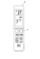
- FIG. 4 is an explanatory diagram showing the appearance of the remote controller of the air conditioner according to the present embodiment.
- the remote controller 40 is operated by the user and transmits an infrared signal to the remote controller receiver Q (see FIG. 1) of the indoor unit.
- the contents of the signal are various commands such as an operation request, a change of a set temperature, a timer, a change of an operation mode, and a stop request.
- the air conditioner A can at least perform indoor cooling, heating, dehumidification, and the like. It may also have other air conditioning functions such as air purification.
- the air conditioner A can adjust the air in the room in various ways.
- the auto-save function switches to the absent energy saving mode when the absence of the human body is recognized during operation, and the auto-off function automatically stops the operation after a predetermined time elapses. .. Details will be described later in FIGS. 7 and 8.
- FIG. 5 is an explanatory diagram showing a configuration of a sensor unit of the air conditioner according to the present embodiment.
- the sensor unit 50 is provided in the indoor unit 100 and the outdoor unit 200.
- the sensor unit 50 includes a room temperature sensor 51 (temperature detection unit), a humidity sensor 52, an infrared sensor 110 (see FIG. 1) as a human detection sensor, an outside temperature sensor, a compressor temperature sensor, a refrigerant pipe temperature sensor, a clock, and the like.
- NS room temperature sensor 51
- temperature detection unit temperature detection unit
- a humidity sensor 52 for a temperature sensor
- an infrared sensor 110 see FIG. 1
- NS refrigerant pipe temperature sensor
- thermopile As the human detection sensor, in addition to the infrared sensor 110, a near infrared sensor, a thermopile, a thermography, a charcoal type sensor, an ultrasonic sensor, and a noise sensor may be used.
- a thermopile for example, it is composed of 1 ⁇ 1 pixel, 4 ⁇ 4 pixel, 1 ⁇ 8 pixel in width ⁇ length, and is installed in the lower part of the center in the left-right direction of the front panel 106 (see FIG. 1). good.
- the image pickup unit may be used as the human detection sensor.
- the human body detection unit 61 (see FIG. 6) detects the position of the human head or the like from the image captured by the imaging unit, and sets the position of the head as the human position. Further, in the present embodiment, in addition to the position of the person, the position of the foot of the person is also detected. The position of the person's feet may be directly detected based on the image captured by the imaging unit, or the position of the person's head or the like may be detected and the person's head or the like may be detected. The position of a person's feet may be estimated from the position of.
- FIG. 6 is an explanatory diagram showing a configuration of a control unit of the air conditioner according to the present embodiment.
- the control unit 60 is provided in the electrical component.
- the control unit 60 drives the blower fan 103, the left and right wind direction plates 104, and the vertical wind direction plate 105 of the indoor unit 100 based on the information from the remote controller 40 via the transmission / reception unit 45 and the information from the sensor unit 50, and the outdoor unit 200.
- the control unit 60 includes a human body detection unit 61 that detects a human body based on the information of the infrared sensor 110, an auto-off function unit 62 that automatically stops operation by an auto-off function when recognizing the absence of a person (human body), and a human body. Absence energy saving operation function unit 63 (auto save function unit) that automatically sets energy saving by auto save function when recognizing absence, air flow control unit 64 that controls the wind direction unit that changes the wind direction of harmonized air, storage unit 65, etc. I have.
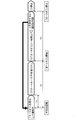
- FIG. 7 is an explanatory diagram showing an outline of the auto-off function according to the present embodiment.
- the auto-off function automatically stops the operation when it recognizes the absence of a person during the operation. Wasteful power consumption due to forgetting to turn off the air conditioner A can be suppressed.
- the auto-off function including the auto-save function will be described. Refer to FIG. 6 as appropriate.
- the control unit 60 sets “auto-off” and recognizes the absence during operation, and after a time T1 (first predetermined time), (1) “auto-save (absence energy saving)” is set. After that, (2) when time T2 (second predetermined time) elapses after recognizing the absence, "auto-off” (pause) is performed.
- T1 first predetermined time
- second predetermined time second predetermined time
- the infrared sensor 110 operates, and when a person is detected, the operation is automatically started. After resuming the operation, if the absence is recognized, the process returns to (1).
- FIG. 8 is a flowchart showing the processing of the auto-off function according to the present embodiment. Refer to FIG. 6 as appropriate.
- the control unit 60 detects the absence (step S81) while the "auto-off" setting is enabled (step S80), proceeds to step S82 if it is absent (step S81, Yes), and if it is not absent (step S81). , No), return to step S81.
- the control unit 60 determines whether or not the time T1 has elapsed since the absence was detected (step S82), and if the time T1 has elapsed (steps S82, Yes), the process proceeds to step S83 and the time T1 has elapsed. If not (steps S82, No), the process returns to step S81.
- step S83 the control unit 60 starts "auto-save", determines whether or not the human body has been detected (step S84), and if it does not detect the human body (steps S84, No), proceeds to step S85. If the human body is detected (step S84, Yes), the process proceeds to step S8A.
- the control unit 60 determines whether or not the time T2 has elapsed since the absence was detected (step S85), and if the time T2 has elapsed (steps S85, Yes), the process proceeds to step S86 and the time T2 has elapsed. If not (steps S85, No), the process returns to step S84.
- step S86 the control unit 60 starts "auto-off", determines whether or not the human body has been detected (step S87), and if it does not detect the human body (steps S87, No), proceeds to step S88. If the human body is detected (step S87, Yes), the process proceeds to step S8B. In step S8B, the control unit 60 starts operation and returns to step S81.
- the control unit 60 determines whether or not the time T3 has elapsed since the start of the "auto-off" (step S88), and if the time T3 has elapsed (step S88, Yes), stops the "auto-off”. (Step S89). On the other hand, if the time T3 has not elapsed (steps S88, No), the control unit 60 returns to step S87.
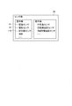
- FIG. 9 is an explanatory diagram showing the validity / invalidity of the auto-off function according to the present embodiment.
- FIG. 9 is a diagram showing the validity / invalidity of the auto-off function, in which the upper limit temperature RT1 and the lower limit temperature RT2 are set as the auto-off permission area. That is, Lower limit temperature RT2 ⁇ room temperature ⁇ upper limit temperature RT1 (1) In the case of, the auto-off function is enabled, Room temperature ⁇ lower limit temperature RT2 or upper limit temperature RT1 ⁇ room temperature (2) In the case of, the auto-off function is disabled as the auto-off prohibited area.
- the pyroelectric infrared sensor makes it difficult to detect a person when the temperature difference between the room temperature and the human body is small. Therefore, there was a possibility of making a judgment that there was a person but not.
- the auto-off is not performed. Further, the farther the distance from the indoor unit 100 is, the more difficult it becomes to detect a person. Even at this time, even if it is determined that a person is present but not present, the auto-off can be prevented when the room temperature is higher than, for example, 30 ° C.
- the auto-off function is disabled in the auto-off prohibited area, so the operation does not stop and the comfort of the room is maintained. can do.
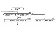
- FIG. 10 is a flowchart showing the process of enabling / disabling the auto-off function according to the present embodiment.
- the control unit 60 determines whether or not the room temperature is within the auto-off permitted region during operation (step S1), and if the room temperature is within the auto-off permitted region (steps S1, Yes), sets “auto-off”. When it is enabled (step S2) and the room temperature is outside the auto-off permitted area (steps S1 and No), the "auto-off" setting is invalidated (step S3), and the process is repeated.
- the process of FIG. 10 and the process of FIG. 8 are parallel processes.
- FIG. 11 is an explanatory diagram showing a change in the set temperature of the auto save function according to the present embodiment.
- the control unit 60 starts "auto save” after the first predetermined time (for example, time T1) after detecting the absence (absence energy saving start). At that time, for example, the control unit 60 raises the temperature by 2 to 3 ° C. from the set temperature of the remote controller 40 during cooling. Specifically, when the set temperature RT0 of the remote controller 40 is set to 28 ° C., it becomes 31 ° C. when the set temperature rises by 3 ° C. in the absence energy saving operation. The setting of 31 ° C. contradicts that the upper limit temperature RT1 is 30 ° C. as the auto-off permitted region, and the control is not intended by the user.
- the first predetermined time for example, time T1
- the control unit 60 raises the temperature by 2 to 3 ° C. from the set temperature of the remote controller 40 during cooling.
- the set temperature RT0 of the remote controller 40 is set to 28 ° C.
- the control unit 60 may set the upper limit temperature of the set temperature during the energy-saving operation within the auto-off permission range. Specifically, the control unit 60 sets the upper limit temperature of the set temperature during the energy-saving operation during cooling to the upper limit temperature RT1 or less, and sets the lower limit temperature of the set temperature during the energy-saving operation during heating to the lower limit temperature RT2 or more.
- FIG. 12 is an explanatory diagram showing other enable / disable of the auto-off function according to the present embodiment.
- the auto-off prohibited region is defined as a case where the room temperature is less than the lower limit temperature RT2 or the room temperature exceeds the upper limit temperature RT1 as shown in the equation (2), but it is not necessary to be limited to this.
- it is determined from the room temperature and the humidity in the room, and conforms to a general WBGT (Wet Bulb Globe Temperature).
- the control unit 60 invalidates the "auto-off" setting in the auto-off prohibited area.
- the air conditioner of the present embodiment described above has the following features.
- the air conditioner A cannot detect a person for a predetermined time (for example, time T2) by the room temperature detecting means (for example, room temperature sensor 51) for detecting the room temperature, the person detecting sensor for detecting a person in the room, and the person detecting sensor.
- the control unit 60 includes a control unit 60 having an auto-off function unit 62 for stopping the operation, and the control unit 60 is in the case where the room temperature is outside the predetermined auto-off permission range while the auto-off function is enabled (see FIG. 9). Disable the auto-off function.
- the auto-off function is set, even if the room temperature is outside the predetermined auto-off permission range, the air conditioning in the room is continued, so that the comfort of the room can be maintained.
- the control unit 60 has an absent energy-saving operation function unit 63 that performs energy-saving operation when it recognizes the absence in the room, and the control unit 60 automatically turns off the upper limit temperature of the set temperature during the energy-saving operation when the auto-off function is enabled. Within the permitted range. As a result, the upper limit temperature of the set temperature during the energy-saving operation can be set within the auto-off permission range, and the comfort of the room can be maintained.
- the control unit 60 can set at least one of the upper limit temperature RT1 of the auto-off permission range and the lower limit temperature RT2 of the auto-off permission range for each operation mode. Specifically, it is considered that the room temperature tends to decrease even if the operation is stopped during heating, and heat stroke does not occur. That is, heating and cooling may be set separately.
- the control unit 60 disables the auto-off function when it is in an area where there is a risk of heat stroke based on the room temperature and humidity. Good (see Figure 12). As a result, the air conditioning in the room is continued, so that the comfort in the room can be maintained.
- a humidity detecting means for example, a humidity sensor 52
- the control unit 60 disables the auto-off function when it is in an area where there is a risk of heat stroke based on the room temperature and humidity. Good (see Figure 12). As a result, the air conditioning in the room is continued, so that the comfort in the room can be maintained.
- the control unit 60 may restart the operation when the room temperature reaches the upper limit temperature or the lower limit temperature of the auto-off permitted range after the operation is stopped. As a result, the comfort of the room can be maintained.
- control unit 60 may notify by voice or buzzer to prompt the restart of the operation. It can contribute to the prevention of heat stroke, hypothermia and freezing.
- the control unit 60 may deliver an e-mail to the terminal of the registration destination registered in advance to the effect that it is out of the auto-off permission range. Specifically, using the Wifi cooperation, an e-mail urging the safety confirmation is delivered to the registered terminal (for example, a smartphone) such as the person or his / her family.
- the registered terminal for example, a smartphone
- the control unit 60 may freeze the outdoor heat exchanger while performing the room temperature recovery (heating) operation.
- the control unit 60 causes the outdoor heat exchanger (see heat exchanger 206 in FIG. 3) to function as an evaporator, and freezes or condenses the outdoor heat exchanger. As a result, small dust adhering to the heat exchanger 206 can be washed away. It is possible to suppress a decrease in heat exchange capacity due to clogging between the fins of the heat exchanger, which has an energy saving effect.
- the human body detection unit 61 may detect a person as a human detection sensor based on the image of the imaging unit. Further, as the human detection sensor, an infrared sensor, a near infrared sensor, a thermopile, a thermography, a charcoal type sensor, an ultrasonic sensor, or a noise sensor may be used. When a thermopile is used as the temperature detection sensor, for example, the thermopile may be composed of 1 ⁇ 1 pixel, 4 ⁇ 4 pixel, and 1 ⁇ 8 pixel in the horizontal ⁇ vertical direction, and may be installed in the lower part of the center of the front panel 106 in the left-right direction.
- the temperature detection sensor can detect the surface temperature of the room, the surface temperature of human clothes, the temperature of human skin, and the surface temperature of each part of the floor, wall, or ceiling.
- Remote control air conditioning control terminal
- Transmission / reception unit 50 Sensor unit 51 Room temperature sensor (room temperature detection means) 52 Humidity sensor 60
- Control unit 61
- Human body detection unit 62
- Auto-off function unit 63
- Absent energy-saving operation function unit (auto-save function unit)
- Airflow control unit 65
- Storage unit 100
- Indoor unit 103
- Blower fan 104
- Left and right wind direction plate (wind direction part)
- Vertical wind direction plate Wind direction part
- Front panel 109b
- Air outlet 110
- Infrared sensor human detection sensor
- Outdoor unit 202
- Compressor 206
- Heat exchanger outdoor heat exchanger
- Propeller fan A Air conditioner RT1 Upper limit temperature RT2 Lower limit temperature
Landscapes
- Engineering & Computer Science (AREA)
- Signal Processing (AREA)
- Chemical & Material Sciences (AREA)
- Combustion & Propulsion (AREA)
- Mechanical Engineering (AREA)
- General Engineering & Computer Science (AREA)
- Physics & Mathematics (AREA)
- Fuzzy Systems (AREA)
- Mathematical Physics (AREA)
- Air Conditioning Control Device (AREA)
Abstract
Description
図2は、本実施形態に係る空気調和機の室内機の構成を示す説明図である。室内機100は、熱交換器102、送風ファン103、左右風向板104(風向部)、上下風向板105(風向部)、前面パネル106、筐体ベース101、各種のセンサ部50(図5参照)などを有している。
図3は、本実施形態に係る空気調和機の室外機の構成を示す説明図である。空気調和機Aの室外機200には、冷媒を圧縮する圧縮機202、高圧の冷媒を減圧する膨張弁、冷媒の流路を切り替える四方弁、外気と冷媒とを熱交換する熱交換器206(室外熱交換器)などの装置を備えている。室外機200は、仕切り板211と電装品箱210とリード線支持部品209とにより、熱交換器室204と機械室205とを区分(分割)している。熱交換器室204には、冷媒配管を循環する冷媒の外気との熱交換を促進するプロペラファン207とその駆動用のモータ、プロペラファン207を回転自在に支持するファン支柱、および外気と循環する冷媒の熱交換を行う熱交換器206が配設されている。機械室205には、循環する冷媒を高温高圧のガス冷媒にする圧縮機202、常温・高圧の液状冷媒を低温・低圧の液状冷媒にする電動膨張弁、電気部品のリアクタ、および、冷媒が流れる冷媒配管の伝熱管が配設されている。電装品箱210には、室外機200を制御する電装品が収納されており、その上部には電装品蓋が被せられている。
図4は、本実施形態に係る空気調和機のリモコンの外観を示す説明図である。リモコン40はユーザによって操作され、室内機のリモコン受信部Q(図1参照)に対して赤外線信号を送信する。当該信号の内容は、運転要求、設定温度の変更、タイマ、運転モードの変更、停止要求などの様々な指令である。空気調和機Aは、これらの信号に基づいて、少なくとも室内の冷房、暖房、除湿などを行うことができる。また、空気清浄など、その他の空気調和の機能を備えていてもよい。空気調和機Aは、室内の空気を様々に調整することができる。
図5は、本実施形態に係る空気調和機のセンサ部の構成を示す説明図である。センサ部50は、室内機100と室外機200に備えられている。センサ部50は、室温センサ51(温度検知部)、湿度センサ52、人検知センサとして赤外線センサ110(図1参照)、外気温センサ、圧縮機温度センサ、冷媒配管温度センサ、時計などにより構成される。
図6は、本実施形態に係る空気調和機の制御部の構成を示す説明図である。制御部60は、電装品に備えられている。制御部60は、送受信部45を介するリモコン40からの情報と、センサ部50からの情報に基づき、室内機100の送風ファン103、左右風向板104、上下風向板105を駆動し、室外機200の圧縮機202、プロペラファン207を駆動する。
下限温度RT2≦ 室温 ≦ 上限温度RT1 (1)
の場合、オートオフ機能の有効であり、
室温<下限温度RT2 又は 上限温度RT1<室温 (2)
の場合、オートオフ禁止領域としてオートオフ機能が無効となる。
空気調和機Aは、室温を検知する室温検知手段(例えば、室温センサ51)と、室内の人を検知する人検知センサと、人検知センサで人を所定時間(例えば、時間T2)検出できない場合に運転停止を行うオートオフ機能部62を有する制御部60と、を備え、制御部60は、オートオフ機能が有効中に、室温が所定のオートオフ許可範囲外の場合(図9参照)、オートオフ機能を無効とする。これにより、オートオフ機能が設定されている際に、室温が所定のオートオフ許可範囲外の場合にも、室内の空調が継続されるため、室内の快適性を維持することができる。
45 送受信部
50 センサ部
51 室温センサ(室温検知手段)
52 湿度センサ
60 制御部
61 人体検出部
62 オートオフ機能部
63 不在省エネ運転機能部(オートセーブ機能部)
64 気流制御部
65 記憶部
100 室内機
103 送風ファン
104 左右風向板(風向部)
105 上下風向板(風向部)
106 前面パネル
109b 空気吹出し口(吹出し口)
110 赤外線センサ(人検知センサ)
200 室外機
202 圧縮機
206 熱交換器(室外熱交換器)
207 プロペラファン
A 空気調和機
RT1 上限温度
RT2 下限温度
Claims (10)
- 室温を検知する室温検知手段と、
室内の人を検知する人検知センサと、
前記人検知センサで前記人を所定時間検出できない場合に運転停止を行うオートオフ機能を有する制御部と、を備え、
前記制御部は、前記オートオフ機能が有効中に、前記室温が所定のオートオフ許可範囲外の場合、前記オートオフ機能を無効とする空気調和機。 - 前記制御部は、前記室内の不在を認識すると、省エネ運転をする不在省エネ運転機能を有し、
前記制御部は、前記オートオフ機能が有効時、前記省エネ運転時の設定温度の上限温度を前記オートオフ許可範囲以内とする
ことを特徴とする請求項1に記載の空気調和機。 - 前記制御部は、運転モード毎に前記オートオフ許可範囲の上限温度、前記オートオフ許可範囲の下限温度のうち少なくともいずれかを設定できる
ことを特徴とする請求項1に記載の空気調和機。 - 前記室内の湿度を検知する湿度検知手段を有し、
前記制御部は、前記室温及び前記湿度に基づいて熱中症に罹る恐れのある領域であるとき、前記オートオフ機能を無効とする
ことを特徴とする請求項1に記載の空気調和機。 - 前記制御部は、前記運転停止後、前記室温が前記オートオフ許可範囲の上限温度または下限温度に到達した場合に、運転を再開する
ことを特徴とする請求項1に記載の空気調和機。 - 前記制御部は、前記運転停止後に前記室温がオートオフ上限温度またはオートオフ下限温度に暫近または到達した場合に、運転再開を促すべく音声またはブザーで報知する
ことを特徴とする請求項1に記載の空気調和機。 - 前記制御部は、前記運転停止後に前記室温がオートオフ上限温度またはオートオフ下限温度に到達した場合は、予め登録された登録先の端末に前記オートオフ許可範囲外になる旨のメールを配信する
ことを特徴とする請求項1に記載の空気調和機。 - 前記制御部は、前記運転停止後に前記室温がオートオフ下限温度に漸近した場合に、室温回復の運転をしながら室外熱交換器の凍結処理をする
ことを特徴とする請求項1に記載の空気調和機。 - 前記人検知センサは、前記人の表面温度を検知する温度検知部、または、焦電型赤外線センサである
ことを特徴とする請求項1に記載の空気調和機。 - 前記人検知センサは、撮像部である
ことを特徴とする請求項1に記載の空気調和機。
Priority Applications (3)
| Application Number | Priority Date | Filing Date | Title |
|---|---|---|---|
| JP2020537784A JP7002662B1 (ja) | 2020-03-16 | 2020-03-16 | 空気調和機 |
| CN202080066758.9A CN114502893A (zh) | 2020-03-16 | 2020-03-16 | 空调机 |
| PCT/JP2020/011442 WO2021186498A1 (ja) | 2020-03-16 | 2020-03-16 | 空気調和機 |
Applications Claiming Priority (1)
| Application Number | Priority Date | Filing Date | Title |
|---|---|---|---|
| PCT/JP2020/011442 WO2021186498A1 (ja) | 2020-03-16 | 2020-03-16 | 空気調和機 |
Publications (1)
| Publication Number | Publication Date |
|---|---|
| WO2021186498A1 true WO2021186498A1 (ja) | 2021-09-23 |
Family
ID=77770749
Family Applications (1)
| Application Number | Title | Priority Date | Filing Date |
|---|---|---|---|
| PCT/JP2020/011442 Ceased WO2021186498A1 (ja) | 2020-03-16 | 2020-03-16 | 空気調和機 |
Country Status (3)
| Country | Link |
|---|---|
| JP (1) | JP7002662B1 (ja) |
| CN (1) | CN114502893A (ja) |
| WO (1) | WO2021186498A1 (ja) |
Citations (3)
| Publication number | Priority date | Publication date | Assignee | Title |
|---|---|---|---|---|
| JP2016197011A (ja) * | 2016-09-01 | 2016-11-24 | ジョンソンコントロールズ ヒタチ エア コンディショニング テクノロジー(ホンコン)リミテッド | 空気調和システム及び空気調和機 |
| JP2017116255A (ja) * | 2017-02-20 | 2017-06-29 | シャープ株式会社 | 送風装置 |
| JP2019219128A (ja) * | 2018-06-21 | 2019-12-26 | 三菱重工サーマルシステムズ株式会社 | 空気調和装置、空気調和システム及び電気機器システム |
Family Cites Families (4)
| Publication number | Priority date | Publication date | Assignee | Title |
|---|---|---|---|---|
| JP4324830B2 (ja) | 2000-03-29 | 2009-09-02 | 株式会社富士通ゼネラル | 空気調和機の制御方法 |
| WO2009081879A1 (ja) | 2007-12-21 | 2009-07-02 | Rohm Co., Ltd. | 情報交換装置 |
| JP6116087B2 (ja) * | 2012-08-31 | 2017-04-19 | ジョンソンコントロールズ ヒタチ エア コンディショニング テクノロジー(ホンコン)リミテッド | 空気調和機および空気調和機の制御方法 |
| JP6765502B2 (ja) | 2017-03-09 | 2020-10-07 | 三菱電機株式会社 | 赤外線検出器、赤外線検出装置及びコントローラ |
-
2020
- 2020-03-16 WO PCT/JP2020/011442 patent/WO2021186498A1/ja not_active Ceased
- 2020-03-16 JP JP2020537784A patent/JP7002662B1/ja active Active
- 2020-03-16 CN CN202080066758.9A patent/CN114502893A/zh active Pending
Patent Citations (3)
| Publication number | Priority date | Publication date | Assignee | Title |
|---|---|---|---|---|
| JP2016197011A (ja) * | 2016-09-01 | 2016-11-24 | ジョンソンコントロールズ ヒタチ エア コンディショニング テクノロジー(ホンコン)リミテッド | 空気調和システム及び空気調和機 |
| JP2017116255A (ja) * | 2017-02-20 | 2017-06-29 | シャープ株式会社 | 送風装置 |
| JP2019219128A (ja) * | 2018-06-21 | 2019-12-26 | 三菱重工サーマルシステムズ株式会社 | 空気調和装置、空気調和システム及び電気機器システム |
Also Published As
| Publication number | Publication date |
|---|---|
| JP7002662B1 (ja) | 2022-01-20 |
| JPWO2021186498A1 (ja) | 2021-09-23 |
| CN114502893A (zh) | 2022-05-13 |
Similar Documents
| Publication | Publication Date | Title |
|---|---|---|
| JP5585556B2 (ja) | 空気調和機 | |
| CN203940582U (zh) | 空调机 | |
| CN104285106B (zh) | 空调装置以及空气调节系统 | |
| JP6125040B2 (ja) | 空調制御装置 | |
| JP6261295B2 (ja) | 空気調和システム | |
| KR101624385B1 (ko) | 공기 조화기 및 공기 조화기의 제어 방법 | |
| CN203771556U (zh) | 室内机和空气调节装置 | |
| KR20110103235A (ko) | 공기조화기 및 그 제어방법 | |
| JP5984453B2 (ja) | 空気調和機の室内機 | |
| JP2009109025A (ja) | 空気調和機用リモコン | |
| JP2016176653A (ja) | 空気調和機 | |
| JP2015206483A (ja) | 空気調和機 | |
| KR100536525B1 (ko) | 공기조화기 | |
| JP6905808B2 (ja) | 空気調和機 | |
| JP2014178059A (ja) | 空気調和機 | |
| JP5429272B2 (ja) | 空気調和機 | |
| JP7002662B1 (ja) | 空気調和機 | |
| JP2017040407A (ja) | 空気調和機 | |
| JP6746246B2 (ja) | 空気調和機 | |
| JP2001193985A (ja) | 空気調和機 | |
| JP6438143B2 (ja) | 空気調和装置の室内機 | |
| JP5797169B2 (ja) | 空気調和機 | |
| JP2017040409A (ja) | 空気調和機 | |
| KR20030000422A (ko) | 공기조화기의 냉/난방 자동절환방법 | |
| JP5429273B2 (ja) | 空気調和機 |
Legal Events
| Date | Code | Title | Description |
|---|---|---|---|
| ENP | Entry into the national phase |
Ref document number: 2020537784 Country of ref document: JP Kind code of ref document: A |
|
| 121 | Ep: the epo has been informed by wipo that ep was designated in this application |
Ref document number: 20926084 Country of ref document: EP Kind code of ref document: A1 |
|
| WWE | Wipo information: entry into national phase |
Ref document number: 202217051127 Country of ref document: IN |
|
| NENP | Non-entry into the national phase |
Ref country code: DE |
|
| 122 | Ep: pct application non-entry in european phase |
Ref document number: 20926084 Country of ref document: EP Kind code of ref document: A1 |