WO2021182401A1 - 線状加熱による金属板の曲げ加工に用いる加熱方案の算出方法 - Google Patents
線状加熱による金属板の曲げ加工に用いる加熱方案の算出方法 Download PDFInfo
- Publication number
- WO2021182401A1 WO2021182401A1 PCT/JP2021/009013 JP2021009013W WO2021182401A1 WO 2021182401 A1 WO2021182401 A1 WO 2021182401A1 JP 2021009013 W JP2021009013 W JP 2021009013W WO 2021182401 A1 WO2021182401 A1 WO 2021182401A1
- Authority
- WO
- WIPO (PCT)
- Prior art keywords
- heating
- target shape
- analysis result
- analysis
- heating line
- Prior art date
- Legal status (The legal status is an assumption and is not a legal conclusion. Google has not performed a legal analysis and makes no representation as to the accuracy of the status listed.)
- Ceased
Links
Images











Classifications
-
- B—PERFORMING OPERATIONS; TRANSPORTING
- B21—MECHANICAL METAL-WORKING WITHOUT ESSENTIALLY REMOVING MATERIAL; PUNCHING METAL
- B21D—WORKING OR PROCESSING OF SHEET METAL OR METAL TUBES, RODS OR PROFILES WITHOUT ESSENTIALLY REMOVING MATERIAL; PUNCHING METAL
- B21D11/00—Bending not restricted to forms of material mentioned in only one of groups B21D5/00, B21D7/00, B21D9/00; Bending not provided for in groups B21D5/00 - B21D9/00; Twisting
- B21D11/20—Bending sheet metal, not otherwise provided for
-
- B—PERFORMING OPERATIONS; TRANSPORTING
- B21—MECHANICAL METAL-WORKING WITHOUT ESSENTIALLY REMOVING MATERIAL; PUNCHING METAL
- B21D—WORKING OR PROCESSING OF SHEET METAL OR METAL TUBES, RODS OR PROFILES WITHOUT ESSENTIALLY REMOVING MATERIAL; PUNCHING METAL
- B21D11/00—Bending not restricted to forms of material mentioned in only one of groups B21D5/00, B21D7/00, B21D9/00; Bending not provided for in groups B21D5/00 - B21D9/00; Twisting
- B21D11/22—Auxiliary equipment, e.g. positioning devices
-
- B—PERFORMING OPERATIONS; TRANSPORTING
- B21—MECHANICAL METAL-WORKING WITHOUT ESSENTIALLY REMOVING MATERIAL; PUNCHING METAL
- B21D—WORKING OR PROCESSING OF SHEET METAL OR METAL TUBES, RODS OR PROFILES WITHOUT ESSENTIALLY REMOVING MATERIAL; PUNCHING METAL
- B21D37/00—Tools as parts of machines covered by this subclass
- B21D37/16—Heating or cooling
-
- G—PHYSICS
- G06—COMPUTING OR CALCULATING; COUNTING
- G06F—ELECTRIC DIGITAL DATA PROCESSING
- G06F30/00—Computer-aided design [CAD]
- G06F30/20—Design optimisation, verification or simulation
- G06F30/23—Design optimisation, verification or simulation using finite element methods [FEM] or finite difference methods [FDM]
Definitions
- the present invention relates to a method for calculating a heating plan used for bending a metal plate by linear heating.
- Linear heating is widely used in the shipbuilding field as a bending technique.
- Linear heating utilizes the thermal deformation that occurs when the surface of a steel sheet is heated with a gas burner, and is a technology that has been used for a long time in many shipyards in Japan.
- This plastic deformation can be controlled by adjusting the heat input to the steel sheet by changing the moving speed of the gas burner to be heated, the mixing ratio of the combustion gas and the inflow oxygen, the distance between the burner and the steel sheet, and the like.
- the bending process by linear heating is a processing technique for bringing a steel sheet closer to a desired curved surface shape by arranging a plurality of heating lines at appropriate positions.
- the deformation that occurs during linear heating is a complicated one in which vertical contraction / horizontal contraction, vertical bending / horizontal bending are mixed, and it depends on the amount of heat input, the moving speed of the gas burner, the heating position, etc. Bending by linear heating is one of the techniques that is difficult to automate because it is extremely difficult.
- a heating plan calculation method used to realize automation of bending by linear heating has been proposed (see, for example, Patent Document 1).
- the present invention has been made in view of such circumstances, and provides a calculation method capable of calculating a heating plan including a plurality of heating lines optimal for bringing a metal plate closer to a target shape.
- the present invention is a method for calculating a heating plan used for bending a metal plate by linear heating, and is a first heating including at least one first heating wire set at a first position of an analysis model of the metal plate.
- the first step of performing a finite element method structural analysis under the conditions and comparing this analysis result with the target shape is repeated by changing the position of the first heating line, and the analysis result of the repeated first trial is The second step of selecting at least one first heating line set in the first trial approaching the target shape as the first selective heating line, the first selective heating line, and the second position of the analysis model were set.
- a finite element method structural analysis is performed under a second heating condition including at least one second heating line, and a second trial for comparing the analysis result with the target shape is repeated by changing the position of the second heating line.
- the present invention includes three steps and a fourth step of selecting at least one second heating line set in the second trial in which the analysis result approaches the target shape among the repeated second trials as the second selective heating line.
- the heating plan includes the first and second selective heating lines, and in the first or third step, the analysis result and the target shape are divided into a plurality of blocks, and the analysis result and the target shape are combined for each block.
- a calculation method characterized by comparing.
- the calculation method of the present invention repeatedly selects the heating lines that approach the target shape from the heating lines set at various positions, a heating plan including a plurality of optimal heating lines for bringing the metal plate closer to the target shape is calculated. can do. Further, by heating the metal plate based on the calculated heating plan, it is possible to deform the metal plate into a shape close to the target shape.
- the analysis result and the target shape are divided into a plurality of blocks, and the analysis result and the target shape are compared for each block, so that the shape is complicated. Can be evaluated appropriately. Therefore, it is possible to create a heating plan having a complicated target shape. In addition, it becomes possible to create a heating plan with a small number of selective heating lines.
- (A) to (c) are explanatory views of the calculation method of one Embodiment of this invention. It is explanatory drawing of the setting method of the heating wire included in the calculation method of one Embodiment of this invention. It is explanatory drawing of the method of selecting the element on the heating wire included in the calculation method of one Embodiment of this invention. It is explanatory drawing of comparison between the analysis result included in the calculation method of one Embodiment of this invention, and a target shape. It is explanatory drawing of comparison between the analysis result included in the calculation method of one Embodiment of this invention, and a target shape. (A) to (e) are heating plans calculated in the simulation.
- (A) to (d) are the analysis results of the structural analysis based on the calculated heating plan.
- (a) is the target shape (bowl shape) used in the simulation, and (b) is the analysis result of the structural analysis based on the calculated heating plan.
- 9 is a graph comparing the target shape and the analysis result in the broken lines AA'shown in FIGS. 9A and 9B.
- 9 is a graph comparing the target shape and the analysis result on the alternate long and short dash line BB'shown in FIGS. 9A and 9B.
- (a) is the target shape (saddle shape) used in the simulation, and (b) is the analysis result of the structural analysis based on the calculated heating plan. This is the heating plan calculated in the simulation.
- This is a heating plan (selective heating wire: 200 lines) created by structural analysis. It is the result of the structural analysis (created shape) using the prepared heating plan and the difference between the result of the structural analysis and the target shape.
- (A) is the result (created shape) of the structural analysis using the heating plan (selective heating wire: 60 lines) created by evaluating the analysis result without dividing and performing the structural analysis
- (b) is this structure. This is the error between the analysis result and the target shape.
- (A) is the result (created shape) of the structural analysis using the heating plan (selective heating wire: 60 lines) created by dividing the analysis result and the target shape into 100 parts, evaluating the analysis result, and performing the structural analysis.
- (B) are errors between the result of this structural analysis and the target shape. It is a graph which showed the change of the error (Z displacement square error sum) between an analysis result and a target shape with an increase in the number of selective heating lines in a heating plan making process. It is a graph which showed the change of the error (Z displacement square error sum) between an analysis result and a target shape with an increase in the number of selective heating lines in a heating plan making process.
- the present invention is a method for calculating a heating plan used for bending a metal plate by linear heating, and is a first heating including at least one first heating wire set at a first position of an analysis model of the metal plate.
- the first step of performing a finite element method structural analysis under the conditions and comparing this analysis result with the target shape is repeated by changing the position of the first heating line, and the analysis result of the repeated first trial is The second step of selecting at least one first heating line set in the first trial approaching the target shape as the first selective heating line, the first selective heating line, and the second position of the analysis model were set.
- a finite element method structural analysis is performed under a second heating condition including at least one second heating line, and a second trial for comparing the analysis result with the target shape is repeated by changing the position of the second heating line. It includes three steps and a fourth step of selecting at least one second heating line set in the second trial in which the analysis result approaches the target shape among the repeated second trials as the second selective heating line.
- the analysis result and the target shape are divided into a plurality of blocks, and the analysis result and the target shape are compared for each block.
- the heating plan includes first and second selective heating lines, and the analysis model is a finite element model having a plurality of elements and a plurality of nodes. Further, in the first step, the analysis result is compared with the target shape using one of the curvature and displacement amount at the node, and in the third step, the analysis result is the curvature and displacement amount at the node. The other of them is used and compared with the target shape. By changing the comparison method in this way, both the calculation speed and the accuracy can be improved.
- the analysis result uses the curvature at the node. It is preferable to compare with the target shape, and when the target shape has both a positive curvature and a negative curvature, in the first and third steps, the analysis result determines the amount of displacement at the node. It is preferable to use and compare with the target shape. This makes it possible to create an excellent heating plan that can steadily bring the analysis result closer to the target shape.
- the metal plate has a front surface and a back surface.
- the first heating line is preferably set to either the front surface or the back surface
- the second heating line is set to either the front surface or the back surface. It is preferable to set to.
- at least one second heating line set in the second trial in which the analysis result approaches the target shape is selected from the repeated second trials, and the selected second heating lines are selected.
- the step is to select the second heating line set on the same surface as the surface on which the first selective heating line is set as the second selective heating line. As a result, it is possible to suppress frequent replacement of the heating surface on which the selective heating line is set, and it is possible to improve the efficiency of the bending process using the heating plan.
- the step is to select a second heating wire having a small amount as the second selective heating wire. As a result, it is possible to prevent the bending amount from becoming too large, and it is possible to reduce the number of selective heating lines included in the heating plan.
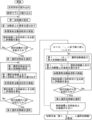
- FIG. 1 is a flowchart of a calculation method of this embodiment
- FIGS. 2 (a) to 2 (c) are explanatory views of a calculation method
- FIG. 3 is an explanatory diagram of a heating line setting method
- FIG. 4 is an explanatory diagram of a method of selecting elements on the heating line.
- the calculation method of this embodiment is the calculation method of the heating plan 6 used for bending a metal plate by linear heating.
- the finite element method structural analysis is carried out under the first heating condition including at least one first heating line 4 set at the first position of the analysis model 2 of the metal plate, and this analysis is performed.
- the first step of comparing the result 3 with the target shape 10 is repeated by changing the position of the first heating line 4, and the first trial in which the analysis result 3 approaches the target shape 10 among the repeated first trials.
- the finite element method structural analysis is carried out under the second heating condition including the two heating wires 4, and the second trial for comparing the analysis result 3 with the target shape 10 is repeated by changing the position of the second heating wire 4.
- the analysis model 2 is a finite element model having a plurality of elements 8 and a plurality of nodes 9.
- the analysis result 3 is compared with the target shape 10 using one of the curvature and displacement at the node 9, and in the third step, the analysis result 3 is the other of the curvature and displacement at the node 9. Is compared with the target shape 10.
- the heating plan 6 includes a first selective heating wire 5 and a second selective heating wire 5.
- the heating line 4 in which the analysis result 3 is closest to the target shape 10 may be selected, and the heating line 4 in which the analysis result 3 is the second or third closest to the target shape 10 may be selected. You may choose. Further, the program of the present embodiment is created so as to cause a computer to execute the calculation method of the present embodiment.
- the calculation method of the present embodiment is a method of calculating a heating plan used for bending a metal plate by linear heating using a finite element method structural analysis (FEM structural analysis).
- the heating plan is a plan for heating and bending a metal plate.
- the analysis model 2 of the metal plate is used.
- the length, width, thickness, etc. of the metal plate are set in the analysis model 2.
- the analysis model 2 of the metal plate has a front surface and a back surface. Further, the analysis model 2 is divided into a plurality of elements (mesh) 8.
- the element 8 may be, for example, a quadrangular or triangular shell, or may be a solid such as a cube, a rectangular parallelepiped, a triangular pyramid, or a triangular prism. Further, each vertex of the element 8 becomes a node 9.
- the analysis model 2 shown in FIG. 2A the analysis model 2 is divided into 20 ⁇ 20 (400) elements 8, and the elements 8 are quadrangular shells. In this case, the analysis model 2 has a grid pattern, and each intersection has a node 9.
- a model of the target shape 10 is used.
- the target shape 10 is a shape that is a target for bending a metal plate.
- the model of the target shape 10 is created by moving the node 9 so that the shape of the analysis model 2 of the metal plate becomes the target shape 10.
- the heating plan 6 can be calculated by causing a computer to execute a program created based on the flowchart shown in FIG.
- the model of the target shape 10 and the analysis model 2 are read into the computer.
- the heating line 4 is set at the first position of the analysis model 2.
- the first position can be randomly set at an arbitrary position of the analysis model 2.
- the first position may be a position included in the front surface of the analysis model 2 of the metal plate, or may be a position included in the back surface of the analysis model 2.
- the heating line 4 may be a straight line or a curved line. Moreover, you may set a plurality of heating lines 4.
- heating wires 4 can be set.
- the heating line 4 is a straight line, as shown in FIG. 3, any two nodes 9 (x 1 , y 1 ) and (x 2 , y 2 ) of the analysis model 2 are randomly selected.
- the heating line 4 can be set on a straight line connecting the two nodes 9.
- the heating line 4a shown in FIG. 2A can be set.
- the heating lines 4a to 4e can be set.
- FIGS. 2 (a) to 2 (c) do not distinguish between the heating wire 4 or the selective heating wire 5 set on the front surface of the metal plate and the heating wire 4 or the selective heating wire 5 set on the back surface of the metal plate.
- the heating lines 4a to 4v and the selective heating line 5 are set on the front surface of the metal plate and some are set on the back surface of the metal plate.
- the finite element method structural analysis is performed using the analysis model 2.
- strain is applied to the selected element 8 to obtain an analysis result 3 (analysis model deformed by structural analysis).
- the heating conditions can include the amount of heat input in addition to the position of the heating wire 4.
- the finite element method structural analysis may be an FEM thermal elasto-plastic analysis or an elastic analysis by the intrinsic strain method.
- linear heating using a gas burner may be assumed, linear heating using a laser (laser forming or the like) may be assumed, or linear heating using induction heating may be assumed.
- material physical characteristics Young's modulus, Poisson's ratio, density, etc.
- the FEM thermal elasto-plastic analysis the vertical contraction, lateral contraction, angular deformation, and vertical contraction of the element 8 selected with respect to the heating conditions (the position of the set heating wire 4 (including the heating surface) and the amount of heat input (J / mm)). Calculate the amount of intrinsic strain of the four components of bending.
- the thermal and deformation histories are sequentially reproduced and the deformation analysis is performed, so that the transient situation can be analyzed.
- the deformation of the metal plate (analysis model 2) due to linear heating is caused by the intrinsic deformation. If this intrinsic deformation is known, the deformation of the metal plate (analysis model 2) due to linear heating can be predicted by adding the intrinsic deformation as a forced strain along the heating wire 4 in the elastic analysis. Therefore, in the elastic analysis by the intrinsic strain method, the structural analysis is performed using the intrinsic strain calculated or measured in advance. For example, the intrinsic strain calculated by FEM thermal elasto-plastic analysis or the intrinsic strain obtained by actually measuring a metal plate deformed by linear heating can be used for elastic analysis by the intrinsic strain method.
- the elastic analysis by the intrinsic strain method can be performed by using an equation expressing the relationship between the amount of heat input calculated or measured in advance and the intrinsic strain.
- the intrinsic strain method is an elastic analysis, the calculation time is considerably shorter than that of the thermal elasto-plastic analysis.
- the analysis result 3 and the target shape 10 are compared, and the error between the analysis result 3 and the target shape 10 is evaluated.
- the evaluation value and the set position of the heating line 4 are stored in the storage unit.
- the evaluation value can be calculated by comparing the analysis result 3 with the target shape 10.
- the analysis result 3 and the target shape 10 can be divided into a plurality of blocks, and the analysis result 3 and the target shape 10 can be compared for each block to calculate the evaluation value.
- the analysis model 2 can be divided into four equal parts, nine equal parts, 16 equal parts, 25 equal parts, 36 equal parts, 49 equal parts, 64 equal parts, 81 equal parts, or 100 equal parts.
- the evaluation value can be calculated by comparing the analysis result 3 of the analysis model as a whole with the target shape 10 and the analysis result of each block and the target shape.
- the evaluation index for example, the out-of-plane displacement amount (displacement amount) or the curvature of the node 9 can be used.
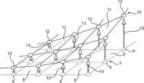
- FIG. 5 is an explanatory diagram of the comparison between the analysis result 3 and the target shape 10 when the analysis result 3 and the target shape 10 are compared as the whole analysis model and the evaluation index is the out-of-plane displacement amount 13 of the node 9. be.
- the amount of displacement d (error) in the out-of-plane direction from the node 9 of the analysis result 3 to the node 12 of the corresponding target shape 10 is calculated.
- the evaluation index is the displacement amount d of the node 9
- the evaluation value can be calculated.
- the evaluation value may be a value ( ⁇ d 2 ) obtained by squaring the displacement amounts d of all the nodes 12 included in the analysis model and adding them together. can.
- FIG. 6 is an explanatory diagram of comparison between the analysis result 3 and the target shape 10 when the analysis result 3 and the target shape 10 are divided into a plurality of blocks and the analysis result 3 and the target shape 10 are compared for each block. ..
- the analytical model is three-dimensional, but FIG. 6 is shown in two dimensions for illustration.
- the analysis result 3 and the target shape 10 are divided into four blocks A to D.
- the least squares straight line (regression straight line) of the node 9 of the analysis result 3 included in the block A is calculated (the least squares plane is calculated in the three-dimensional analysis model).
- the orientation of the analysis result 3 and the direction of the target shape 10 become the same, and the local error between the analysis result 3 and the target shape 10 is appropriately evaluated. be able to.
- the difference (displacement amount) d 1 to d 5 of the z-axis coordinates of the node 9 of the analysis result 3 and the node 12 of the target shape corresponding thereto is calculated.
- d 1 z 1- z 6
- d 2 z 2- z 7
- d 3 z 3- z 8
- d 4 z 4- z 9
- d 5 z 5- z 10 .
- the evaluation value (sum of squared errors) is calculated in the same manner as for block A. Then, the evaluation value of the analysis result can be calculated by adding the evaluation values of all the blocks A to D included in the analysis model.
- the evaluation index is the curvature of the node 9
- the error (curvature error r) between the curvature of the node 9 of the analysis result 3 and the curvature of the node 12 of the target shape 10 corresponding to the node 9 is calculated.
- the evaluation value can be calculated.
- the evaluation value may be a value ( ⁇ r 2 ) obtained by squaring the curvature errors r of all the nodes 9 included in the analysis model and adding them together. can.
- the evaluation value of each block is used. Is the sum of the squared displacements d of all the nodes 12 (after rotation) included in the block ( ⁇ d 2 ) and the curvature error r of all the nodes 12 included in the block. It can be the product of the value ( ⁇ r 2).
- Whether to use the displacement amount, the curvature, or both the displacement amount and the curvature as the evaluation index can be determined in consideration of the target shape, processing efficiency, and the like.
- the flow from the setting of the heating line 4 to the preservation of the evaluation value and the position of the set heating line 4 is called the first trial.
- the second trial basically has the same flow as the first trial, but the heating line 4 of the second trial is set at a position different from the setting position of the heating line 4 of the first trial.
- This position can be randomly set at an arbitrary position of the analysis model 2. Further, this position may be a position included in the front surface of the analysis model 2 of the metal plate, or may be a position included in the back surface of the analysis model 2.
- the heating line 4 may be a straight line or a curved line.
- the element 8 on the set heating wire 4 is selected, the finite element method structural analysis is performed, and the analysis result 3 is obtained.
- the obtained analysis result 3 and the target shape 10 are compared, and an evaluation value is calculated. Further, the calculated evaluation value and the set position of the heating line 4 are stored in the storage unit.
- Such a trial is repeated X times. For example, as shown in FIG. 2A, the position of the heating line 4 is set to the heating line 4c to 4k, and the trial can be performed at each position. Further, in each trial, a plurality of heating lines 4 can be set and the trial can be performed. For example, when setting five heating wires, five heating wires 4 are set in each trial and the trial is performed.
- the heating line 4 in the trial in which the error (evaluation value) between the analysis result 3 and the target shape 10 in each trial is the smallest is selected as the selective heating line 5.
- the heating line 4 in the trial in which the error (evaluation value) between the analysis result 3 and the target shape 10 is the second, third, fourth, or fifth is may be selected as the selective heating line 5.
- Which trial the heating line 4 is selected as the selective heating line 5 can be determined in consideration of the target shape 10, the size of the bending amount, and the like.
- the plurality of heating lines 4 are selected as the selective heating lines 5.
- the heating line 4d can be selected from the heating lines 4a to 4k shown in FIG. 2A.
- heating lines 4f to 4j can be selected.
- the process from the first trial to the selection of the selective heating line 5 is referred to as the first heating line selection flow.
- the second heating line selection flow is basically the same flow as the first heating line selection flow, but when the heating lines 4 are randomly set at arbitrary positions in the analysis model 2, the first heating is performed. Both the selective heating line 5 selected in the line selection flow and the heating line 4 randomly set in each trial of the second heating line selection flow are set, and the element 8 on the selective heating line 5 and the set heating line 4 are set. Select the above element 8. Then, by performing the structural analysis under these heating conditions, it is possible to obtain an analysis result 3 that reflects both the selective heating line 5 and the set heating line 4. In the second heating line selection flow, a plurality of heating lines 4 may be set in each trial.
- the number of heating lines 4 set in each trial of the first heating line selection flow and the number of heating lines 4 set in each trial of the second heating line selection flow may be different. ..
- the selective heating line 5 and the heating line 4l shown in FIG. 2B can be set.
- the selective heating lines (heating lines 4f to 4j) selected in the first heating line selection flow and the heating lines 4l to 4p can be set.
- the trials are repeated up to X times, and the heating line 4 in the trial in which the error (evaluation value) between the analysis result 3 and the target shape 10 is the smallest in each trial is selected as the selective heating line 5.
- the heating line 4 in the trial in which the error (evaluation value) between the analysis result 3 and the target shape 10 is the second or third smallest may be selected as the selective heating line 5.
- the plurality of heating lines 4 are selected as the selective heating lines 5.
- the heating line 4s can be selected from the heating lines 4l to 4v shown in FIG. 2 (b).
- heating lines 4l to 4p can be selected.
- Each heating line selection flow (referred to as the Ath heating line selection flow) is basically the same flow as the first heating line selection flow, but at least one heating line 4 at an arbitrary position in the analysis model 2 At least one heating line 4 randomly set in each trial of the Ath heating line selection flow and all the selections selected in the (A-1) or earlier heating line selection flow when randomly setting The heating wire 5 is set. Further, in each trial of the A-th heating line selection flow, a plurality of heating lines 4 can be set and the trial can be performed. For example, when setting five heating lines 4, the five heating lines 4 randomly set in each trial and all the selective heating lines 5 selected in the heating line selection flow before the (A-1) th time.
- the trials are repeated up to X times, and the heating line 4 in the trial in which the error (evaluation value) between the analysis result 3 and the target shape 10 is the smallest in each trial is selected as the selection heating line 5.
- the heating line 4 in the trial in which the error (evaluation value) between the analysis result 3 and the target shape 10 is the second or third smallest may be selected as the selective heating line 5.
- the heating plan 6 including the selective heating wire 5 selected in the 1st to nth heating wire selection flow is completed.
- the heating plan 6 includes, for example, a plurality of selective heating lines 5 as shown in FIG. 2 (c).
- an upper limit can be set for the number of heating line selection flows. This upper limit can be set to a number exceeding the number of selective heating wires 5 considered necessary to reach the first target shape 10. As a result, it is possible to prevent the number of selective heating wires 5 included in the heating plan from becoming too large, and it is possible to prevent the heating plan from becoming a heating plan with a high processing cost.
- the displacement amount is used as an index for evaluating the error between the analysis result 3 and the target shape 10 (evaluation using the displacement amount).
- the curvature can be used as an index for evaluating the error between the analysis result 3 and the target shape 10 (the evaluation value is calculated using the curvature). That is, when moving from the A-th heating line selection flow to the (A + 1) th heating line selection flow, the index for evaluating the error between the analysis result 3 and the target shape 10 is changed from the displacement amount to the curvature or from the curvature to the displacement amount. Switch to.
- the displacement amount is used as an index for evaluating the error between the analysis result 3 and the target shape 10
- the analysis result 3 Curvature can be used as an index for evaluating the error between the target shape and the target shape 10.
- the processing speed can be increased by heating in the selective heating line 5 selected in the heating line selection flow using the displacement amount, and the processing accuracy in the heating in the selective heating line 5 selected in the heating line selection flow using the curvature. Can be raised. Therefore, it is possible to achieve both processing efficiency and processing accuracy. Further, the calculation may proceed while selecting whether to use the displacement amount, the curvature, or both the displacement amount and the curvature as the error evaluation index for each heating line selection flow according to the analysis result.
- the bending process of the metal plate may be performed by an operator or may be performed automatically by a machine.
- a plurality of selective heating wires 5 may be heated at the same time.
- the heating plan 6 can include the order of the selective heating lines 5 corresponding to the order of the heating line selection flows.
- the selective heating wire 5 can be heated according to this order. This makes it possible to deform the metal plate into a shape closer to the target shape.
- the coordinate measuring device may be a contact type, or may be a scanning laser probe type or an optical type non-contact type. This makes it possible to deform the metal plate into a shape closer to the target shape.
- a processing device that automatically processes a metal plate based on the heating plan 6 can include, for example, a heating unit that heats the metal plate and a control unit that controls the processing device.
- the control unit is provided so that the heating plan 6 can be read in, and is provided so as to control the heating unit so as to heat the metal plate according to the heating plan 6.
- an index for evaluating an error between the analysis result 3 and the target shape 10 is determined based on the target shape 10. Specifically, when the target shape 10 has either a positive curvature or a negative curvature (for example, when the target shape 10 is a bowl shape), the error between the analysis result 3 and the target shape 10 The curvature at node 9 is used as an index for evaluating. As a result, the analysis result 3 can be steadily approached to the target shape 10 from the first heating line selection flow to the nth heating line selection flow, and an excellent heating plan can be created.
- the target shape 10 has both a positive curvature and a negative curvature (for example, when the target shape 10 is a saddle type, a twist type, etc.), the error between the analysis result 3 and the target shape 10 is evaluated.
- the amount of displacement at the node 9 is used as an index to be used.
- the analysis result 3 can be steadily approached to the target shape 10 from the first heating line selection flow to the nth heating line selection flow, and an excellent heating plan can be created.
- Other configurations are the same as those in the first embodiment.
- the description of the first embodiment also applies to the second embodiment as long as there is no contradiction.
- the selective heating wire 5 selected in the immediately preceding heating wire selection flow is set to the same heating surface as the set heating surface (either the front surface or the back surface of the metal plate).
- a heating plan is created while preferentially selecting the heating wire 4.
- a plurality of trials having a small error (evaluation value) between the analysis result 3 and the target shape 10 are selected. For example, when 500 trials are performed, 10 trials having a small error (evaluation value) between the analysis result 3 and the target shape 10 are selected. Further, the number of trials to be selected can be, for example, 2 or more and 10 or less.
- the trial in which the heating line 4 is set on the same heating surface as the heating surface on which the selective heating line 5 selected in the (A-1) th heating line selection flow is set.
- the trial heating line 4 having the smallest error (evaluation value) between the analysis result 3 and the target shape 10 is selected as the selective heating line 5.
- the selective heating line 5 set on the same heating surface can be continued.
- FIG. 2B a trial in which the selective heating line 5 (4d) selected in the immediately preceding heating line selection flow is set on the surface of the metal plate and the heating line 4s is set on the surface of the metal plate, the metal plate.
- the trial in which the heating wire 4q is set and the trial in which the heating wire 4q is set are small.
- the error (evaluation value) between the analysis result 3 of the trial in which the heating line 4v is set and the target shape 10 is smaller than the error (evaluation value) between the analysis result 3 of the trial in which the heating line 4s is set and the target shape 10 Even so, the heating line 4s set on the same heating surface as the selective heating line 5 (4d) is selected as the selective heating line 5.
- the trial in which the heating line 4 is set on the same heating surface as the heating surface on which the selected heating line 5 selected in the (A-1) th heating line selection flow is set is not included.
- the heating line 4 of the trial having the smallest error (evaluation value) between the analysis result 3 and the target shape 10 is selected as the selective heating line 5.
- the heating surfaces are replaced.
- Other configurations are the same as in the first or second embodiment.
- the description of the first or second embodiment also applies to the third embodiment as long as there is no contradiction.
- the heating wire 4 having a small bending amount is preferentially selected as the selective heating wire 5 in the heating wire selection flow.
- the bending amount is possible to prevent the bending amount from becoming too large, and it is possible to reduce the number of selective heating lines 5 included in the heating plan. If the bending amount is too large, it becomes necessary to set the selective heating wire 5 in order to correct the excessively bent portion, and the number of the selective heating wire 5 included in the heating plan tends to increase.
- a plurality of trials having a small error (evaluation value) between the analysis result 3 and the target shape 10 are selected.
- the heating line 4 set in the trial with the smaller bending amount among the selected plurality of trials is selected as the selective heating line 5.
- the bending amount of the trial in which the heating line 4d is set is smaller than the trial in which the heating line 4a is set and the trial in which the heating line 4j is set, the analysis result of the trial in which the heating line 4a is set and the trial in which the heating line 4j is set Even if the error (evaluation value) between 3 and the target shape 10 is smaller than the error (evaluation value) between the analysis result 3 of the trial in which the heating line 4d is set and the target shape 10 is selected, the heating line 4d is selected. Select as heating wire 5. Further, among the plurality of selected trials, the trial in which the bending amount is too large can be excluded from the candidates for the selective heating wire 5. Other configurations are the same as those of the first, second or third embodiment. Further, the description of the first, second or third embodiment also applies to the fourth embodiment as long as there is no contradiction.
- a heating plan (target shape: bowl type, saddle type, torsion type) is calculated using the calculation method of the present invention (structural analysis: elastic analysis by the intrinsic strain method), and the calculated heating scheme is used by the intrinsic strain method.
- a simulation was performed to perform elastic analysis (structural analysis).
- the intrinsic strain applied to the element for the deformation analysis by the intrinsic strain method was obtained from the deformation result by performing FEM thermal elasto-plastic analysis on the analysis model.
- a plate-shaped analysis model with a plate length of 500 mm and a plate width of 500 mm is used, and the analysis model is a quadrangular shell element so that the number of nodes and the number of elements are 2,601 and 2,500, respectively. Divided.
- the material of the metal plate was assumed to be SM490A (rolled steel for welded structure), and the plate thickness was assumed to be 16 mm.
- the material constants of SM490A are shown in Table 1. In the simulation, three types (bowl type, saddle type, and twist type) were set as the target shapes. The number of trials spent in determining the position of one selective heating wire was set to 500.
- FIGS. 7 (a) to 7 (e) are heating plans calculated assuming that the number of selective heating lines is 10, 20, 30, 40, and 55, respectively
- (D) are the analysis results when the structural analysis by the intrinsic strain method is performed based on the heating plan calculated by assuming that the number of selective heating lines is 10, 20, 30, and 40, respectively.
- FIG. 9A shows the target shape used for the structural analysis
- FIG. 9B shows the analysis result when the structural analysis is performed by the intrinsic strain method based on the heating plan calculated with the number of selective heating lines being 55.
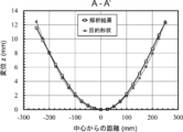
- FIG. 10 shows an out-of-plane displacement distribution comparing the target shape and the analysis result in the broken lines AA'of FIGS. 9 (a) and 9 (b)
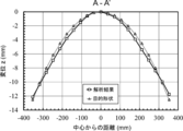
- FIG. 11 shows one point in FIGS. 9 (a) and 9 (b). It is an out-of-plane displacement distribution comparing the target shape and the analysis result on the chain line BB'.
- the curvature at the node was used as an index to evaluate the error between the target shape and the analysis result.
- the number of selective heating wires was 10, 20, 30, 40, and 55.
- the heating plan shown in FIGS. 7A to 7E could be calculated.
- the analysis results shown in FIGS. 8 (a) to 8 (d) and 9 (b) could be obtained.
- the solid line in FIG. 7 represents the selective heating line on the front surface of the metal plate, and the dotted line represents the selective heating line on the back surface of the metal plate.
- FIGS. 8A to 8D when the number of selective heating lines is 10, the bowl-shaped tendency is captured, and when the number of selective heating lines is 20, a shape that almost matches the target shape is formed. I found that it was done. After that, it was confirmed that the shape was finely adjusted or the number of selective heating lines that had almost no effect on the shape increased. Focusing on the heating positions shown in FIG. 7, it was found that many selective heating lines were arranged in the diagonal direction of the base metal. In order to form a bowl-shaped shape with a dent in the center, the position of the selective heating line is selected so that the entire base metal is bent evenly using both angular deformation and vertical bending. It is considered that this is the result.
- Target shape Saddle shape Fig. 12 (a) is the target shape used for structural analysis, and Fig. 12 (b) is structural analysis by the intrinsic strain method based on the heating plan calculated assuming that the number of selective heating lines is 40. It is the analysis result at the time.
- FIG. 13 is a heating plan calculated assuming that the number of selective heating lines is 40.
- FIG. 14 is an out-of-plane displacement distribution comparing the target shape and the analysis result in the broken lines AA'of FIGS. 12 (a) and 12 (b), and FIG. 15 is one point of FIGS. 12 (a) and 12 (b). It is an out-of-plane displacement distribution comparing the target shape and the analysis result on the chain line BB'.
- the out-of-plane displacement amount at the node was used as an index to evaluate the error between the target shape and the analysis result.
- the number of selective heating wires was set to 40.
- the heating plan shown in FIG. 13 could be calculated.
- the analysis result shown in FIG. 12B could be obtained. It was confirmed that the analysis results shown in FIGS. 12, 14, 15 to 12 (b) well captured the tendency of the target shape.
- FIG. 16 Twist type Fig. 16 (a) is the target shape used for structural analysis, and Fig. 16 (b) is structural analysis by the intrinsic strain method based on a heating plan calculated with 16 selective heating lines. It is the analysis result at the time.
- FIG. 17 is a heating plan calculated assuming that the number of selective heating lines is 16.
- FIG. 18 is an out-of-plane displacement distribution comparing the target shape and the analysis result in the broken lines AA'of FIGS. 16 (a) and 16 (b), and FIG. 19 shows one point of FIGS. 16 (a) and 16 (b). It is an out-of-plane displacement distribution comparing the target shape and the analysis result on the chain line BB'.
- the amount of displacement in the out-of-plane direction at the node is used as an index for evaluating the error between the target shape and the analysis result. Further, the number of selective heating wires was set to 16. In this simulation, the heating plan shown in FIG. 17 could be calculated. Moreover, when the structural analysis by the intrinsic strain method was performed based on the calculated heating plan, the analysis result shown in FIG. 16B could be obtained. It was confirmed that the analysis results shown in FIGS. 16, 18, 19 to 16 (b) well captured the tendency of the target shape.
- Target shape Bowl shape (evaluation of evaluation index)
- the target shape was a bowl shape (Fig. 9 (a)), and the structural analysis was performed using the displacement amount, curvature, or both the displacement amount and the curvature as the index for evaluating the error between the analysis result and the target shape, and a heating plan was created.
- FIG. 20 is a graph showing the change in the error between the analysis result and the target shape as the number of selective heating lines increases in the process of creating the heating plan.
- the sum of the Z displacement squared errors on the vertical axis of FIG. 20 is the sum of the squares of the displacement amounts in the z direction (out-of-plane direction, the direction orthogonal to the front surface and the back surface of the initial metal plate) at the nodes.
- evaluation value ( ⁇ d 2 ) ⁇ ⁇ ( ⁇ r 2 ) ⁇ was used.
- ⁇ d 2 is the value obtained by squared and added the displacement amounts d of all the nodes included in the analysis model
- ⁇ r 2 is the value obtained by squared and added the curvature errors r of all the nodes included in the analysis model.
- the sum of Z displacement squared errors was 100 or more even when the number of selective heating lines was 50.
- the sum of Z-displacement squared errors decreased significantly until the number of selective heating lines increased to 5, but after that, the sum of Z-displacement squared errors gradually decreased. bottom. Further, even if the number of selective heating lines reached 50, the sum of Z displacement squared errors was 10 or more.
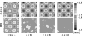
- Target shape Complex shape (evaluation of the number of divisions) A heating plan was created by performing structural analysis with the complex shape shown in FIGS. 21 and 22 as the target shape. In this target shape, the convex portions 16 and the concave portions 17 are arranged alternately. In this structural analysis, the displacement amount is used as an index for evaluating the error between the analysis result and the target shape. Further, in this structural analysis, the analysis result and the target shape were divided into four, 16 or 64 divisions, and the analysis result and the target shape were compared for each block to calculate the evaluation value. Further, when comparing the analysis result and the target shape for each block, the analysis result and the target shape are rotated so that the direction of the analysis result and the direction of the target shape are the same. We also performed structural analysis without division.
- evaluation value (sum of squared errors of the whole) ⁇ ⁇ ⁇ (sum of squared errors in each block) ⁇ , and the evaluation value is small.
- the selective heating line in the trial was selected.
- the sum of squared errors is the sum of the squares of the displacements in the z-direction (out-of-plane direction, the direction orthogonal to the front and back surfaces of the initial metal plate) at the nodes.
- the "sum of squared errors in the whole” in the formula is a value that contributes to the retention of the overall shape
- the "sum of squared errors in each block” in the formula is used to create a local shape. It is a value that contributes.
- ⁇ is the weight of the overall error
- ⁇ is the weight of the local error.
- FIG. 23 is a heating plan (selective heating lines: 200 lines) created by structural analysis.
- FIG. 24 shows the result of the structural analysis (created shape) using the created heating plan, and the difference between the result of the structural analysis and the target shape.
- Target shape Bowl shape (evaluation of the number of divisions)
- a heating plan was created by performing structural analysis using the target shape as a bowl shape (FIG. 9 (a)) and the displacement amount as an index for evaluating the error between the analysis result and the target shape.
- the analysis result and the target shape were divided into 4, 16, 64, or 100 divisions, and the analysis result and the target shape were compared for each block to calculate the evaluation value.
- structural analysis was also performed without division, using the evaluation value as the sum of the squared errors of the whole.
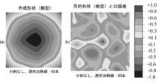
- FIG. 26 (a) shows the result (created shape) of the structural analysis using the heating plan (selective heating lines: 60 lines) created by evaluating the analysis result without dividing and performing the structural analysis
- FIG. 26 (b). Is the error between the result of this structural analysis and the target shape.
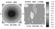
- FIG. 27 (a) shows the result of structural analysis (created shape) using the heating plan (selective heating lines: 60 lines) created by dividing the analysis result and the target shape into 100 parts, evaluating the analysis result, and performing structural analysis.
- 27 (b) shows the error between the result of this structural analysis and the target shape.
- FIG. 28 is a graph showing a change in the error (Z displacement squared error sum) between the analysis result and the target shape as the number of selective heating lines increases in the process of creating the heating plan.
- Target shape Bowl shape (evaluation of weight parameters) A heating plan was created by performing structural analysis using the target shape as a bowl shape (FIG. 9 (a)) and the displacement amount as an index for evaluating the error between the analysis result and the target shape.
- the analysis result and the target shape were divided into 64 parts, and the analysis result and the target shape were compared for each block to calculate the evaluation value.
- ⁇ is the weight of the overall error and ⁇ is the weight of the local error.
- ⁇ was set to 0 or 1
- ⁇ was set to 0, 1, 2, 4, 8, 16 or 32.
- FIG. 29 is a graph showing a change in the error (Z displacement squared error sum) between the analysis result and the target shape as the number of selective heating lines increases in the process of creating the heating plan.
- ⁇ and ⁇ are shown in FIG. From these results, it was found that an excellent heating plan can be obtained when ⁇ is set to about 8.
Landscapes
- Engineering & Computer Science (AREA)
- Mechanical Engineering (AREA)
- Physics & Mathematics (AREA)
- Theoretical Computer Science (AREA)
- Computer Hardware Design (AREA)
- Evolutionary Computation (AREA)
- Geometry (AREA)
- General Engineering & Computer Science (AREA)
- General Physics & Mathematics (AREA)
- Investigating Or Analyzing Materials Using Thermal Means (AREA)
- Investigating Strength Of Materials By Application Of Mechanical Stress (AREA)
- Shaping Metal By Deep-Drawing, Or The Like (AREA)
Priority Applications (3)
| Application Number | Priority Date | Filing Date | Title |
|---|---|---|---|
| JP2022507182A JP7570118B2 (ja) | 2020-03-09 | 2021-03-08 | 線状加熱による金属板の曲げ加工に用いる加熱方案の算出方法 |
| KR1020227034181A KR20220151638A (ko) | 2020-03-09 | 2021-03-08 | 선상 가열에 의한 금속판의 굽힘 가공에 사용하는 가열방안의 산출방법 |
| CN202180019670.6A CN115243810B (zh) | 2020-03-09 | 2021-03-08 | 在利用线状加热的金属板的弯曲加工中使用的加热方案的计算方法 |
Applications Claiming Priority (2)
| Application Number | Priority Date | Filing Date | Title |
|---|---|---|---|
| JP2020-039947 | 2020-03-09 | ||
| JP2020039947 | 2020-03-09 |
Publications (1)
| Publication Number | Publication Date |
|---|---|
| WO2021182401A1 true WO2021182401A1 (ja) | 2021-09-16 |
Family
ID=77672354
Family Applications (1)
| Application Number | Title | Priority Date | Filing Date |
|---|---|---|---|
| PCT/JP2021/009013 Ceased WO2021182401A1 (ja) | 2020-03-09 | 2021-03-08 | 線状加熱による金属板の曲げ加工に用いる加熱方案の算出方法 |
Country Status (4)
| Country | Link |
|---|---|
| JP (1) | JP7570118B2 (https=) |
| KR (1) | KR20220151638A (https=) |
| CN (1) | CN115243810B (https=) |
| WO (1) | WO2021182401A1 (https=) |
Families Citing this family (1)
| Publication number | Priority date | Publication date | Assignee | Title |
|---|---|---|---|---|
| CN120715036B (zh) * | 2025-08-25 | 2026-01-06 | 福建科宝金属制品有限公司 | 一种热轧平整机组平整花纹板的控制方法 |
Citations (9)
| Publication number | Priority date | Publication date | Assignee | Title |
|---|---|---|---|---|
| JPH0775835A (ja) * | 1993-09-07 | 1995-03-20 | Ishikawajima Harima Heavy Ind Co Ltd | 線状加熱による金属板の曲げ加工方法 |
| JP2002192240A (ja) * | 2000-12-26 | 2002-07-10 | Ishikawajima Harima Heavy Ind Co Ltd | 線状加熱の加熱方案策定方法 |
| JP2002219522A (ja) * | 2001-01-22 | 2002-08-06 | Ishikawajima Harima Heavy Ind Co Ltd | 線状加熱による金属板の鞍型曲面加工方法 |
| JP2005118824A (ja) * | 2003-10-16 | 2005-05-12 | Ihi Marine United Inc | 大曲率曲面の加工に適した線状加熱方案の算出方法 |
| KR20080105522A (ko) * | 2007-05-31 | 2008-12-04 | 삼성중공업 주식회사 | 선체 외판 곡면 가공 시스템 및 그 방법 |
| JP2009012057A (ja) * | 2007-07-06 | 2009-01-22 | Ihi Corp | 線状加熱曲げ加工の加熱位置修正方法 |
| JP2010194599A (ja) * | 2009-02-26 | 2010-09-09 | Ihi Corp | 自動鋼板曲げ装置による加熱位置修正方法及び装置 |
| JP2013066902A (ja) * | 2011-09-21 | 2013-04-18 | Ihi Marine United Inc | 線状加熱の加熱方案算出方法 |
| JP2020040092A (ja) * | 2018-09-11 | 2020-03-19 | 公立大学法人大阪 | 線状加熱による金属板の曲げ加工に用いる加熱方案の算出方法 |
Family Cites Families (4)
| Publication number | Priority date | Publication date | Assignee | Title |
|---|---|---|---|---|
| JP4471412B2 (ja) * | 1999-02-22 | 2010-06-02 | 株式会社アイ・エイチ・アイ マリンユナイテッド | 曲げ加工用金属板の展開形状選定方法 |
| JP2009012058A (ja) * | 2007-07-06 | 2009-01-22 | Ihi Corp | 線状加熱による金属板の曲げ加工方法及び装置 |
| JP5150230B2 (ja) * | 2007-12-11 | 2013-02-20 | 株式会社アイ・エイチ・アイ マリンユナイテッド | 曲げ加工方法及び曲げ加工支援装置 |
| DE102016212933A1 (de) * | 2016-07-14 | 2018-01-18 | Hochschule Heilbronn | Kompensation der Rückfederung bei der Herstellung von Blechumformteilen |
-
2021
- 2021-03-08 WO PCT/JP2021/009013 patent/WO2021182401A1/ja not_active Ceased
- 2021-03-08 JP JP2022507182A patent/JP7570118B2/ja active Active
- 2021-03-08 KR KR1020227034181A patent/KR20220151638A/ko active Pending
- 2021-03-08 CN CN202180019670.6A patent/CN115243810B/zh active Active
Patent Citations (9)
| Publication number | Priority date | Publication date | Assignee | Title |
|---|---|---|---|---|
| JPH0775835A (ja) * | 1993-09-07 | 1995-03-20 | Ishikawajima Harima Heavy Ind Co Ltd | 線状加熱による金属板の曲げ加工方法 |
| JP2002192240A (ja) * | 2000-12-26 | 2002-07-10 | Ishikawajima Harima Heavy Ind Co Ltd | 線状加熱の加熱方案策定方法 |
| JP2002219522A (ja) * | 2001-01-22 | 2002-08-06 | Ishikawajima Harima Heavy Ind Co Ltd | 線状加熱による金属板の鞍型曲面加工方法 |
| JP2005118824A (ja) * | 2003-10-16 | 2005-05-12 | Ihi Marine United Inc | 大曲率曲面の加工に適した線状加熱方案の算出方法 |
| KR20080105522A (ko) * | 2007-05-31 | 2008-12-04 | 삼성중공업 주식회사 | 선체 외판 곡면 가공 시스템 및 그 방법 |
| JP2009012057A (ja) * | 2007-07-06 | 2009-01-22 | Ihi Corp | 線状加熱曲げ加工の加熱位置修正方法 |
| JP2010194599A (ja) * | 2009-02-26 | 2010-09-09 | Ihi Corp | 自動鋼板曲げ装置による加熱位置修正方法及び装置 |
| JP2013066902A (ja) * | 2011-09-21 | 2013-04-18 | Ihi Marine United Inc | 線状加熱の加熱方案算出方法 |
| JP2020040092A (ja) * | 2018-09-11 | 2020-03-19 | 公立大学法人大阪 | 線状加熱による金属板の曲げ加工に用いる加熱方案の算出方法 |
Also Published As
| Publication number | Publication date |
|---|---|
| CN115243810A (zh) | 2022-10-25 |
| CN115243810B (zh) | 2026-01-13 |
| KR20220151638A (ko) | 2022-11-15 |
| JPWO2021182401A1 (https=) | 2021-09-16 |
| JP7570118B2 (ja) | 2024-10-21 |
Similar Documents
| Publication | Publication Date | Title |
|---|---|---|
| JP7165395B2 (ja) | 金属板を線状加熱し曲げ加工する加工方法 | |
| CN116422905B (zh) | 用于粉末床熔融工艺的激光扫描方法、装置和存储介质 | |
| CN115488887B (zh) | 一种基于焊接变形预测的轨迹规划的方法、装置及设备 | |
| WO2021182401A1 (ja) | 線状加熱による金属板の曲げ加工に用いる加熱方案の算出方法 | |
| Kilian | Fabrication of partially double-curved surfaces out of flat sheet material through a 3D puzzle approach | |
| WO2022191301A1 (ja) | 加熱方案の算出方法、プログラム、記録媒体、装置、変形方法、板変形装置、および変形板の製造方法 | |
| KR101042056B1 (ko) | 가변 금형을 이용한 강판의 곡면성형방법 | |
| CN117182104A (zh) | 一种选区激光熔化制作高温合金悬桥的方法、装置及设备 | |
| WO2021182334A1 (ja) | 線状加熱による金属板の曲げ加工に用いる加熱方案の算出方法 | |
| JP2013066902A (ja) | 線状加熱の加熱方案算出方法 | |
| JP2006231345A (ja) | 曲げ加工方法、金属板、加熱位置決定プログラム、及び3次元形状処理装置 | |
| JP2003211230A (ja) | 線状加熱の加熱方案算出方法 | |
| JP2666685B2 (ja) | 線状加熱による金属板の曲げ加工方法 | |
| CN119098656A (zh) | 一种基于三维扫描点云的电弧增材制造焊道形貌预测方法 | |
| KR102554788B1 (ko) | 판재의 곡률 측정 방법 | |
| JP4471412B2 (ja) | 曲げ加工用金属板の展開形状選定方法 | |
| KR101043426B1 (ko) | 강판의 곡면 가공시 부재 뒤집기 시점 판단 방법 및 그 장치 | |
| KR20220058137A (ko) | 선체 곡 외판 성형시스템 및 방법 | |
| CN118260881B (zh) | 一种焊接结构的仿真模拟方法 | |
| JP2022037637A (ja) | ひずみ取りのための加熱方案の作成方法 | |
| CN117000872B (zh) | 双向曲率板材的渐进弯曲顺序成形方法、设备及存储介质 | |
| JP2009297790A (ja) | 曲げ加工方法、金属板、加熱位置決定プログラム及び装置 | |
| JP2024086034A (ja) | 熱変形解析方法 | |
| Bian et al. | New kind of subarea-parallel scanning mode for laser metal deposition shaping | |
| CN120941146A (zh) | 非球面元件的抛光加工方法及装置 |
Legal Events
| Date | Code | Title | Description |
|---|---|---|---|
| 121 | Ep: the epo has been informed by wipo that ep was designated in this application |
Ref document number: 21767566 Country of ref document: EP Kind code of ref document: A1 |
|
| DPE1 | Request for preliminary examination filed after expiration of 19th month from priority date (pct application filed from 20040101) | ||
| ENP | Entry into the national phase |
Ref document number: 2022507182 Country of ref document: JP Kind code of ref document: A |
|
| ENP | Entry into the national phase |
Ref document number: 20227034181 Country of ref document: KR Kind code of ref document: A |
|
| NENP | Non-entry into the national phase |
Ref country code: DE |
|
| 122 | Ep: pct application non-entry in european phase |
Ref document number: 21767566 Country of ref document: EP Kind code of ref document: A1 |