WO2021182006A1 - インホイールモータ車両のサスペンションシステム - Google Patents
インホイールモータ車両のサスペンションシステム Download PDFInfo
- Publication number
- WO2021182006A1 WO2021182006A1 PCT/JP2021/005174 JP2021005174W WO2021182006A1 WO 2021182006 A1 WO2021182006 A1 WO 2021182006A1 JP 2021005174 W JP2021005174 W JP 2021005174W WO 2021182006 A1 WO2021182006 A1 WO 2021182006A1
- Authority
- WO
- WIPO (PCT)
- Prior art keywords
- vehicle
- wheel motor
- suspension
- air
- drive device
- Prior art date
- Legal status (The legal status is an assumption and is not a legal conclusion. Google has not performed a legal analysis and makes no representation as to the accuracy of the status listed.)
- Ceased
Links
Images






Classifications
-
- B—PERFORMING OPERATIONS; TRANSPORTING
- B60—VEHICLES IN GENERAL
- B60G—VEHICLE SUSPENSION ARRANGEMENTS
- B60G17/00—Resilient suspensions having means for adjusting the spring or vibration-damper characteristics, for regulating the distance between a supporting surface and a sprung part of vehicle or for locking suspension during use to meet varying vehicular or surface conditions, e.g. due to speed or load
- B60G17/015—Resilient suspensions having means for adjusting the spring or vibration-damper characteristics, for regulating the distance between a supporting surface and a sprung part of vehicle or for locking suspension during use to meet varying vehicular or surface conditions, e.g. due to speed or load the regulating means comprising electric or electronic elements
-
- B—PERFORMING OPERATIONS; TRANSPORTING
- B60—VEHICLES IN GENERAL
- B60G—VEHICLE SUSPENSION ARRANGEMENTS
- B60G17/00—Resilient suspensions having means for adjusting the spring or vibration-damper characteristics, for regulating the distance between a supporting surface and a sprung part of vehicle or for locking suspension during use to meet varying vehicular or surface conditions, e.g. due to speed or load
- B60G17/015—Resilient suspensions having means for adjusting the spring or vibration-damper characteristics, for regulating the distance between a supporting surface and a sprung part of vehicle or for locking suspension during use to meet varying vehicular or surface conditions, e.g. due to speed or load the regulating means comprising electric or electronic elements
- B60G17/016—Resilient suspensions having means for adjusting the spring or vibration-damper characteristics, for regulating the distance between a supporting surface and a sprung part of vehicle or for locking suspension during use to meet varying vehicular or surface conditions, e.g. due to speed or load the regulating means comprising electric or electronic elements characterised by their responsiveness, when the vehicle is travelling, to specific motion, a specific condition, or driver input
Definitions
- the present invention relates to a suspension system for an in-wheel motor vehicle.
- Patent Document 1 Japanese Patent Application Laid-Open No. 2015-214273 includes a housing including a motor and a speed reducer, and in an in-wheel motor unit arranged at a position where the axle and the motor shaft are offset, a portion connecting a suspension to the housing is provided. It is disclosed that by fixing the (ball joint), it is possible to arrange the connecting portion in the wheel.
- Patent Document 2 discloses that an air spring type spension can be applied as a suspension of an in-wheel motor drive device.
- the in-wheel motor vehicle in which the motor is installed inside the wheel has the following problems.
- the resonance frequency on the spring is 1 Hz
- the resonance frequency under the spring is 10 Hz.
- the vibration between the resonance points frequencies Fa-Fb
- the meshing of the gears of the in-wheel motor drive or the meshing of the motor Vibration due to the resonance of forced vibration is easily transmitted to the vehicle body via the suspension.
- the meshing of the gears of the in-wheel motor drive device or the forced vibration of the motor is amplified under driving conditions such as starting (acceleration) from the vehicle stopped state, running at extremely low speed, and starting on a slope, so that the driver can use it. I feel uncomfortable.
- the suspension connected to the in-wheel motor drive device is generally of the coil spring type.
- the vibration from the in-wheel motor drive device 100 is transmitted to the spring 150, and the vibration is amplified with the resonance of the spring 150.
- the noise inside the vehicle body 90 (inside the vehicle) will worsen.
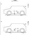
- the driving force of the motor is transmitted to the ground contact point of the tire on the outer periphery of the wheel. Therefore, for example, in a four-wheel drive type in-wheel motor vehicle, as shown in FIG. 16A, the in-wheel motor drive device (not shown) mounted on the wheels (front wheels and rear wheels) 91 and 92 is used.
- the force is applied, a force for lowering the vehicle body 90 is generated at the instantaneous rotation center 91c of the front wheels 91, and a force for lifting the vehicle body 90 is generated at the instantaneous rotation center 92c of the rear wheels 92. Then, at the time of power running, a phenomenon occurs in which the front side of the vehicle body 90 sinks and the rear side is lifted.
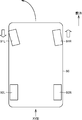
- the in-wheel drive device on the turning outer ring side (right wheels 91R and 92R in FIG. 17) is powered and turned.
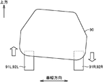
- Left and right independent control is performed by regenerating the in-wheel drive device on the inner wheel side (left wheels 91L and 92L in FIG. 17). Therefore, since the roll is promoted when turning, the vehicle body 90 may tilt and the posture of the vehicle 9 may be disturbed as shown in FIG.
- the present invention has been made to solve the above-mentioned problems, and an object of the present invention is to suppress noise in a vehicle interior and to suppress or prevent disturbance of the posture of an in-wheel motor vehicle. To provide a suspension system.
- a suspension system is a suspension system for an in-wheel motor vehicle in which an in-wheel motor drive is mounted on at least a pair of wheels arranged so as to face each other along the vehicle width direction. ..
- the in-wheel motor drive includes a motor unit that drives the wheels, a wheel hub bearing unit that is attached to the wheel, and a deceleration unit that decelerates the rotation of the motor unit and transmits it to the wheel hub bearing unit.
- This suspension system controls the air suspension provided between each in-wheel motor drive and the vehicle body, and the air suspension when the in-wheel motor drive is driven or regenerated, to determine the spring constant and vehicle height. It is provided with suspension control means for changing at least one of them.
- the in-wheel motor drive is mounted on at least the front wheels.
- the suspension system further includes a detection means for detecting the running state of the vehicle, and the suspension control means sets the spring constant of the air suspension arranged on the front wheels from the reference level when the turning is detected by the detection means. It is also desirable to increase.
- suspension control means may set the spring setting of the air suspension arranged on the front wheels to be higher than the reference level when the detection means detects straight movement and the in-wheel motor drive device runs or regenerates. desirable.
- the in-wheel motor drive device may also be mounted on the rear wheels.
- the suspension control means keeps the spring constant of the air suspension arranged on the rear wheels at the reference level when the turning is detected by the detection means.
- the suspension control means detects straight movement by the detection means and the in-wheel motor drive device runs or regenerates, the spring constants of the air suspensions arranged on both the front wheels and the rear wheels are set from the reference level. May also be higher.
- suspension control means raises the vehicle height of the air suspension on the turning inner ring side to be higher than the vehicle height of the air suspension on the turning outer ring side when the turning is detected by the detecting means.
- the suspension control means raises the vehicle height of the air suspension arranged on the front wheels to a level higher than the reference level when the detection means detects the straight movement and the in-wheel motor drive device drives the vehicle.
- the detection means detects the straight movement and the in-wheel motor drive device drives the vehicle.
- the in-wheel motor drive device regenerates, the vehicle height of the air suspension arranged on the front wheels is lowered below the reference level.
- the suspension control means maintains the vehicle height of the air suspension arranged on the rear wheels at the reference level when turning is detected by the detection means. You may.
- the suspension control means sets the vehicle height of the air suspension arranged on the front wheels higher than the vehicle height of the air suspension arranged on the rear wheels when the detection means detects straight movement and the in-wheel motor drive device drives.
- the height of the air suspension arranged on the front wheels is higher than the height of the air suspension arranged on the rear wheels. It is also desirable to lower it.
- the present invention it is possible to suppress noise in the vehicle interior and suppress or prevent disturbance of the posture of the in-wheel motor vehicle.
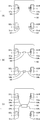
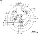
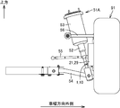
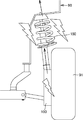
- (A) to (C) are diagrams schematically showing an arrangement example of a compressor of an air suspension in an in-wheel motor vehicle according to an embodiment of the present invention. It is a schematic view of a double wishbone type air suspension seen from the inside in the vehicle width direction. It is a schematic diagram which looked at the double wishbone type air suspension from the front or the rear. It is a graph which shows the difference of the resonance frequency of an in-wheel motor vehicle and an on-board motor vehicle.
- FIG. 17 It is a schematic diagram conceptually showing a problem when a coil spring type suspension is applied.
- (A) and (B) are schematic diagrams conceptually showing the force applied to the vehicle body when the in-wheel motor drive device runs and regenerates in the in-wheel motor vehicle.
- In-wheel motor It is a schematic diagram conceptually showing that the in-wheel motor drive devices of the left and right wheels are independently controlled when the vehicle turns. It is a schematic view seen from the XVIII direction of FIG. 17, and is the figure which conceptually shows the force applied to the vehicle body when an in-wheel motor vehicle turns.
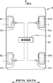
- the in-wheel motor vehicle (hereinafter, may be abbreviated as “vehicle”) 9 is, for example, a four-wheel drive vehicle, with front wheels 91L, 91R and rear wheels 92L, 92R.
- An in-wheel motor drive device 1 is mounted on each of the above.
- the front wheels 91L and 91R are wheels arranged in pairs on the front side of the vehicle 9, and the rear wheels 92L and 92R are wheels arranged in pairs on the rear side of the vehicle 9.
- the front wheels 91L and 91R and the rear wheels 92L and 92R are arranged so as to face each other along the vehicle width direction (left-right direction) of the vehicle 9, respectively.
- the in-wheel motor drive device 1 mounted on each wheel is connected to the vehicle body 90 via an air spring type suspension (suspension device).
- the front wheels 91L and 91R are provided with air suspensions 51a and 51b, respectively, and the rear wheels 92L and 92R are provided with air suspensions 51c and 51d, respectively.
- front wheels 91 when it is not necessary to distinguish the left and right of the front wheels 91L and 91R, these are referred to as front wheels 91, and when it is not necessary to distinguish the left and right of the rear wheels 92L and 92R, these are referred to as rear wheels 92. It is called. When it is not necessary to distinguish between the front wheels 91 and the rear wheels 92, these are referred to as wheels 91. Similarly, when it is not necessary to distinguish between the four air suspensions 51a to 51d, these are referred to as air suspensions 51.
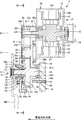
- FIG. 2 is a developed sectional view showing an in-wheel motor drive device 1 according to an embodiment of the present invention.
- the right side of the paper surface represents the inside in the vehicle width direction (inboard side)
- the left side of the paper surface represents the outside in the vehicle width direction (outboard side).
- the cross section shown in FIG. 2 is a developed plane in which a plane including the axis M and the axis N shown in FIG. 3 and a plane including the axis N and the axis O are connected in this order.
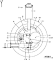
- FIG. 3 is a schematic cross-sectional view showing the inside of the in-wheel motor drive device 1, and shows a state in which the in-wheel motor drive device 1 is cut in III-III in FIG. 2 and the cross section is viewed in the direction of the arrow.
- each gear is represented by a tooth tip circle in order to avoid complication of drawing.
- the right side of the paper represents the front of the vehicle
- the left side of the paper represents the rear of the vehicle
- the upper side of the paper represents the upper part of the vehicle
- the lower side of the paper represents the lower part of the vehicle.
- the inside in the vehicle width direction is viewed from the outside in the vehicle width direction in the axis O direction.
- the in-wheel motor drive device 1 decelerates the rotation of the wheel hub bearing portion 11 provided in the center of the wheel 91, the motor portion 21 for driving the wheel 91, and the motor portion 21 and transmits the deceleration to the wheel hub bearing portion 11.
- a unit 31 is provided.
- the motor unit 21 and the deceleration unit 31 are arranged offset from the axis O of the wheel hub bearing unit 11.
- the axis O extends in the vehicle width direction and coincides with the axle.
- the wheel hub bearing portion 11 is arranged on one axis direction (outboard side) of the in-wheel motor drive device 1
- the motor portion 21 is arranged on the other axis direction (inboard side) of the in-wheel motor drive device 1.
- the deceleration unit 31 is arranged on one side of the motor unit 21 in the axial direction, and the axial position of the deceleration unit 31 overlaps with the axial position of the wheel hub bearing portion 11.
- the in-wheel motor drive device 1 is housed in the inner space region of the wheel W of the wheel 91.
- the motor unit 21 may protrude inward in the vehicle width direction from the inner space region of the wheel W.
- the wheel hub bearing portion 11 is, for example, a rotating inner ring / fixed outer ring, and the inner ring 12 as a rotating wheel (hub ring) coupled to the wheel W of the wheel 91 and a fixed ring coaxially arranged on the outer diameter side of the inner ring 12.
- the outer ring 13 and a plurality of rolling elements 14 arranged in the annular space between the inner ring 12 and the outer ring 13 are provided.
- the outer ring 13 penetrates the opening 39p formed in the front portion 39f of the main body casing 39.
- the main body casing 39 refers to a casing including the outer shell of the deceleration unit 31, and accommodates the rotating element of the deceleration unit 31.
- the front portion 39f is a casing wall portion that covers one end of the deceleration portion 31 in the axis O direction of the main body casing 39.
- the outer ring 13 is fixed to the front portion 39f of the main body casing 39 via the hub attachment 42.
- the outer ring 13 has a protruding portion 13g that protrudes in the radial direction, and the protruding portion 13g is attached and fixed to the hub attachment 42 by the first bolt 43.
- the hub attachment 42 is attached and fixed to the main body casing 39 by a second bolt 44.
- the inner ring 12 is a tubular body longer than the outer ring 13, and is passed through the central hole of the outer ring 13.
- a hub flange 12f is formed at one end of the inner ring 12 protruding from the outer ring 13 to the outside of the in-wheel motor drive device 1 in the axis O direction.
- the inner ring 12 is coupled to the wheel W by the hub flange 12f and rotates integrally with the wheel 91.
- a plurality of rows of rolling elements 14 are arranged in the annular space between the inner ring 12 and the outer ring 13.
- the outer peripheral surface of the inner ring 12 at the center of the axis O direction constitutes the inner raceway surface of the plurality of rolling elements 14 arranged in the first row.
- An inner raceway ring 12r is fitted on the outer periphery of the other end of the inner ring 12 in the O-direction.
- the outer peripheral surface of the inner raceway ring 12r constitutes the inner raceway surface of the plurality of rolling elements 14 arranged in the second row.
- the inner peripheral surface of one end of the outer ring 13 in the O-direction of the axis constitutes the outer raceway surface of the rolling elements 14 in the first row.
- the inner peripheral surface of the other end of the outer ring 13 in the O-axis direction constitutes the outer raceway surface of the rolling elements 14 in the second row.
- the sealing material 16 is further interposed in the annular space between the inner ring 12 and the outer ring 13.
- the sealing material 16 seals both ends of the annular space to prevent dust and foreign matter from entering.
- the output shaft 38 of the speed reduction unit 31 is inserted into the center hole at the other end of the inner ring 12 in the O-direction of the axis and fitted.
- Such fitting is spline fitting or serration fitting.
- the motor unit 21 has a motor rotating shaft 22, a rotor 23, a stator 24, and a motor casing 29, and is sequentially arranged from the axis M of the motor unit 21 to the outer diameter side in this order.
- the motor unit 21 is an inner rotor or outer stator type radial gap motor, but may be another type of electric motor.
- the motor casing 29 surrounds the outer circumference of the stator 24.
- One end of the motor casing 29 in the axis M direction is coupled to the back surface portion 39b of the main body casing 39.
- the other end of the motor casing 29 in the M direction along the axis is sealed with a plate-shaped motor casing cover (hereinafter referred to as "rear cover") 29v.
- the back surface portion 39b is a casing wall portion that covers the other end of the reduction unit 31 in the axis M direction (axis O direction) of the main body casing 39.
- the main body casing 39 and the motor casing 29 form a casing 10 that forms the outer shell of the in-wheel motor drive device 1.
- casing 10 When it is not necessary to distinguish between the main body casing 39 and the motor casing 29 in the following description, it is simply referred to as casing 10.
- the stator 24 includes a cylindrical stator core 25 and a coil 26 wound around the stator core 25.
- the stator core 25 is formed by laminating ring-shaped steel plates in the M direction of the axis.
- Both ends of the motor rotating shaft 22 are rotatably supported by the back surface portion 39b of the main body casing 39 and the rear cover 29v of the motor portion 21 via rolling bearings 27 and 28.
- Most of the motor rotating shaft 22 except for one end 22e in the axial direction is arranged in the motor casing 29.
- One end 22e in the axial direction is arranged in the main body casing 39. That is, the motor rotating shaft 22 is housed in the casing 10 of the in-wheel motor driving device 1.
- the axis M which is the center of rotation of the motor rotation shaft 22 and the rotor 23, extends parallel to the axis O of the wheel hub bearing portion 11.
- the motor portion 21 is offset so as to be separated from the axis O of the wheel hub bearing portion 11 toward the front side of the vehicle.
- the speed reduction unit 31 includes an input shaft 32 coaxially coupled to the motor rotation shaft 22 of the motor unit 21, an input gear 33 coaxially provided on the outer peripheral surface of the input shaft 32, and a plurality of intermediate gears 34 and 36, and intermediate gears 34 and 36 thereof.
- An intermediate shaft 35 connected to the center of the gears 34 and 36, an output shaft 38 connected to the inner ring 12 of the wheel hub bearing portion 11, and an output gear 37 coaxially provided on the outer peripheral surface of the output shaft 38, and a plurality of these.
- It has a main body casing 39 for accommodating gears and a rotating shaft. Since the main body casing 39 forms the outer shell of the deceleration unit 31, it is also referred to as a deceleration unit casing.
- the input gear 33 is a helical gear with external teeth.
- the input shaft 32 has a hollow structure, and one end portion 22e of the motor rotating shaft 22 in the axial direction is inserted into the hollow hole 32h to perform spline fitting or serration fitting so that the motor rotating shaft 22 cannot rotate relative to each other.
- the input shaft 32 is rotatably supported on both ends of the input gear 33 by the front portion 39f and the back portion 39b of the main body casing 39 via rolling bearings 32a and 32b.
- the axis N which is the center of rotation of the intermediate shaft 35 of the deceleration unit 31, extends parallel to the axis O. Both ends of the intermediate shaft 35 are rotatably supported by the front portion 39f and the back portion 39b of the main body casing 39 via rolling bearings 35a and 35b.
- a first intermediate gear 34 is coaxially provided at the other end of the intermediate shaft 35 in the N direction of the axis.
- a second intermediate gear 36 is coaxially provided in the central region of the intermediate shaft 35 in the N direction of the axis.
- the first intermediate gear 34 and the second intermediate gear 36 are helical gears with external teeth, and the diameter of the first intermediate gear 34 is larger than the diameter of the second intermediate gear 36.
- the large-diameter first intermediate gear 34 is arranged on the other side of the second intermediate gear 36 in the N direction of the axis and meshes with the small-diameter input gear 33.
- the small-diameter second intermediate gear 36 is arranged on one side of the first intermediate gear 34 in the N direction of the axis and meshes with the large-diameter output gear 37.
- the axis N of the intermediate axis 35 is arranged above the axis O and the axis M. Further, the axis N of the intermediate shaft 35 is arranged in front of the vehicle with respect to the axis O and behind the vehicle with respect to the axis M.
- the speed reduction unit 31 is a three-axis parallel shaft gear speed reducer having axes O, N, and M arranged at intervals in the front-rear direction of the vehicle and extending in parallel with each other, and has a two-speed shift.
- the output gear 37 is a helical gear with external teeth, and is coaxially provided at the center of the axis O of the output shaft 38.
- the output shaft 38 extends along the axis O.
- One end of the output shaft 38 in the O-direction is inserted into the center hole of the inner ring 12 and fitted so as not to rotate relative to each other.
- the central portion of the output shaft 38 in the O-direction is rotatably supported by the front portion 39f of the main body casing 39 via the rolling bearing 38a.
- the other end of the output shaft 38 in the axis O direction is rotatably supported by the back surface portion 39b of the main body casing 39 via the rolling bearing 38b.
- the reduction gear 31 includes a small-diameter drive gear and a large-diameter driven gear, that is, an input gear 33 and a first intermediate gear 34, and a second intermediate gear 36 and an output gear 37.
- the rotation of the input shaft 32 is decelerated and transmitted to the output shaft 38.
- the rotating element from the input shaft 32 to the output shaft 38 of the speed reducing unit 31 constitutes a drive transmission path that transmits the rotation of the motor unit 21 to the inner ring 12.
- the main body casing 39 includes a tubular portion in addition to the above-mentioned front portion 39f and back portion 39b.
- the tubular portion covers the internal parts of the speed reduction unit 31 so as to surround the axes O, N, and M extending in parallel with each other.
- the plate-shaped front portion 39f covers the internal component of the speed reducing portion 31 from one side in the axial direction and is coupled to one end of the tubular portion.
- the plate-shaped back surface portion 39b covers the internal component of the speed reducing portion 31 from the other side in the axial direction and is coupled to the other end of the tubular portion.
- the back surface portion 39b of the main body casing 39 is also a partition wall that is coupled to the motor casing 29 and partitions the internal space of the deceleration unit 31 and the internal space of the motor unit 21.
- the motor casing 29 is supported by the main body casing 39 and projects from the main body casing 39 to the other side in the axial direction (inside in the vehicle width direction).
- the main body casing 39 partitions the internal space of the deceleration unit 31, and accommodates all the rotating elements (rotating shaft and gears) of the deceleration unit 31 in the internal space.
- Lubricating oil that lubricates the motor unit 21 and the speed reduction unit 31 is stored in the oil storage unit 30 that occupies the lower part of the internal space of the main body casing 39.
- the rotor 23 of the motor unit 21 rotates, and the rotation is output from the motor rotation shaft 22 to the reduction unit 31.
- the speed reduction unit 31 decelerates the rotation input from the motor unit 21 to the input shaft 32, and outputs the rotation from the output shaft 38 to the wheel hub bearing unit 11.
- the inner ring 12 of the wheel hub bearing portion 11 rotates at the same rotation speed as the output shaft 38, and drives the wheel 91 attached and fixed to the inner ring 12.
- the in-wheel motor drive device 1 having the above configuration is mounted on each wheel 91 of the vehicle 9 shown in FIG.
- the internal configuration of the in-wheel motor drive device 1 is also common to the front wheels 91 and the rear wheels 92, and typically, the output characteristics of the motor unit 21 and the reduction ratio of the reduction unit 31 are related to the front wheels 91 and the rear wheels 92. Is the same.
- the reduction gear 31 is a parallel 3-axis gear reducer having axis lines O, N, and M extending in parallel with each other, but parallel with a plurality of gears meshing with each other. If it is a shaft type gear reducer, it may have two or four shafts or more. Alternatively, the reduction gear 31 may be composed of a reduction gear other than the parallel shaft gear reduction gear.
- FIG. 4 shows a state in which the wheels (front wheels) 91 are viewed from the inside in the vehicle width direction
- FIG. 5 shows a state in which the wheels (front wheels) 91 are viewed from the rear of the vehicle.
- the air suspension 51 is, for example, a MacPherson strut type suspension, which includes a damper 52 extending in the vertical direction, an air spring 53, a lower arm 54 extending in the vehicle width direction, and a tie rod 55.
- a MacPherson strut type suspension which includes a damper 52 extending in the vertical direction, an air spring 53, a lower arm 54 extending in the vehicle width direction, and a tie rod 55.
- the air suspension 51 is fixed to the in-wheel motor drive device 1 via, for example, a suspension bracket 41.
- the suspension bracket 41 is attached to a region of the inner end surface of the casing 10 in the vehicle width direction, which is located behind the motor portion 21 (motor casing 29).
- the suspension bracket 41 includes a main body 41d fixed to the main casing 39 by bolts 45, a damper connecting portion 41a connected to the lower end of the damper 52, and a lower arm connecting to the outer end of the lower arm 54 in the vehicle width direction.
- a portion (not shown) and a tie rod connecting portion 41c connected to the outer end portion of the tie rod 55 in the vehicle width direction are integrally included.
- FIG. 6 is a diagram schematically showing a circuit configuration example of the air suspension 51.
- the air suspension 51 has an air chamber 61 formed by a rubber diaphragm and a rolling guide, and has a structure in which air is filled therein.
- the air chamber 61 is provided around the rod 62 of the damper 52 and constitutes the air spring 53. Since the elasticity of the air spring 53 is realized by rubber and air, the air spring 53 has less natural vibration than the coil spring. Therefore, in the vehicle 9, the vibration via the spring is suppressed, and there is an effect that the noise inside the vehicle can be reduced.
- the electric cable (power line or signal line) 81 extending from the in-wheel motor drive device 1 can be routed to the damper 52 and the air spring 53 and guided to the vehicle body 90 side.
- the air compressed by the compressor 64 driven by the motor 63 is guided to the supply valve 65.
- the amount of air in the air chamber 61 is adjusted while keeping the capacity of the air chamber 61 constant.
- the vehicle height can be made variable. Specifically, when raising the vehicle height, air is supplied to the air chamber 61 to increase the air volume, and when lowering the vehicle height, air is removed from the air chamber 61 to reduce the air volume.
- a separately placed sub tank 66 is connected to the air chamber 61, and the air capacity (size of the air chamber) is adjusted by opening and closing the cut valve 67.
- the spring constant can be made variable. Specifically, when the spring constant is low (soft), the cut valve 67 is opened to increase the volume of the air spring 53, and when the spring constant is high (hard), the cut valve 67 is closed. The volume of the air spring 53 is controlled to be reduced.
- Such an air suspension 51 is provided between the in-wheel motor drive device 1 mounted on each wheel 91 and the vehicle body 90. As shown in FIG. 1, each air suspension 51 is controlled by a control device (suspension control means) 70 provided on the vehicle body 90 side.
- the control device 70 controls the air suspension 51 to change at least one of the spring constant and the vehicle height when the in-wheel motor drive device 1 mounted on the wheels 91 powers or regenerates.
- power running refers to a state in which the motor unit 21 is driven in a state where the speed and torque have the same sign, such as when the vehicle 9 is accelerating
- “regeneration” refers to a state in which the vehicle 9 is decelerated (braking).
- a state in which neither is the case while the vehicle is running is called “coasting".
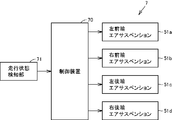
- FIG. 7 is a block diagram schematically showing the functional configuration of the suspension system 7 for the in-wheel motor vehicle 9.
- the suspension system 7 includes the above-mentioned control device 70, air suspensions 51a to 51d, and a traveling state detecting unit (detecting means) 71 for detecting the traveling state of the vehicle 9.
- the running state detection unit 71 detects the running state by detecting, for example, the driver's steering wheel operation and pedal operation.
- the running state includes at least a straight running state and a turning state.
- the control device 70 functions as a suspension control means, and controls the air suspensions 51a to 51d according to the detection result by the traveling state detection unit 71.
- the control device 70 is realized by a computer including a memory and a processor. The method of controlling the air suspensions 51a to 51d by the control device 70 will be described in detail later.
- FIG. 8 is a flowchart showing the spring constant adjustment process according to the present embodiment.
- FIG. 9 is a flowchart showing the vehicle height adjustment process according to the present embodiment. These processes are executed by the control device 70.
- the spring constant adjustment process and the vehicle height adjustment process may be performed in parallel (simultaneously), or only one of them may be performed. In the latter case, one of the spring constant adjustment process and the vehicle height adjustment process may be performed according to the mode selected by the user.
- the suspension system 7 further includes an operation unit (not shown) for allowing the user to select either the spring constant adjustment mode or the vehicle height adjustment mode.
- the spring constant adjustment process shown in FIG. 8 is started when the vehicle 9 is in a runnable state (when the power is turned on).
- the spring constant can be changed in at least two steps, low level and high level.
- the spring constants of all the wheels are set to a low level (soft). That is, the reference level of the spring constant is a low level.
- the cut valve 67 of each air suspension 51 is in the open state, and the capacity of the air spring 53 is set large.
- the control device 70 determines the traveling state of the vehicle 9 detected by the traveling state detecting unit 71 (step S11). If the vehicle 9 is traveling straight, the traveling state is determined to be a straight traveling state, and the process proceeds to step S13. If the vehicle 9 is turning, the traveling state is determined to be the turning state, and the process proceeds to step S19.
- step S13 the control device 70 determines whether or not the traveling state of the vehicle 9 is further coasting. That is, it is determined whether or not the vehicle 9 is traveling straight at a constant speed. If the traveling state of the vehicle 9 is straight and coasting, that is, if the in-wheel motor driving device 1 is not in the power running or regenerative state (YES in step S13), all the spring constants of the front wheels 91 and the rear wheels 92 are used as reference. The level (low level) is set (step S15). That is, the spring constants of all the air suspensions 51a to 51d are controlled to be the reference level.
- step S13 when the traveling state of the vehicle 9 is not in the coasting state, that is, when the in-wheel motor driving device 1 is in the power running or regenerative state (NO in step S13), all the spring constants of the front wheels 91 and the rear wheels 92 are referred to. Raise it above the level (step S17). That is, the spring constant is changed from low level to high level. More specifically, the control device 70 controls to reduce the capacity of the air spring 53 by closing the cut valve 67 of each air suspension 51. As a result, the air springs 53 are in a hard state on both the front wheels 91 and the rear wheels 92, so that the inclination of the vehicle body 90 in the front-rear direction as shown in FIGS. 16A and 16B can be suppressed. As a result, the driver's discomfort can be reduced.
- step S19 the control device 70 raises only the spring constant of the front wheels 91 above the reference level regardless of the turning direction of the vehicle 9. That is, the spring constant of the rear wheel 92 is not changed and remains at the reference level.
- the control device 70 closes the cut valves 67 of the air suspensions 51a and 51b arranged on the front wheels 91, and controls to reduce the capacity of the air spring 53.
- the air springs 53 of the air suspensions 51a and 51b of the front wheels 91 are in a hard state, so that the inclination of the vehicle body 90 in the left-right direction as shown in FIG. 18 can be suppressed.
- the spring constant of the rear wheels 92 is not changed when the vehicle 9 turns (in step S19), but the spring constant of the rear wheels 92 is not limited, and the spring constant of the rear wheels 92 is the spring constant of the front wheels 91. It should be lower than.
- the spring constants of all the air suspensions 51 are set lower than those of the coil springs, so that the resonance frequency (Fa') on the springs (Fa') is conceptually shown in the graph of FIG. ) Can be lower than the resonance frequency Fa of the in-wheel motor vehicle to which the coil spring type suspension is applied. That is, the resonance frequencies above and below the spring can be separated. Then, in order to change the spring constant from a low level to a high level (the spring constant gradually increases) under traveling conditions such as acceleration from a vehicle stopped state, traveling at an extremely low speed, and starting on a slope, the deceleration unit 31 is moved. Since the meshing of the constituent gears or the overlap between the forced vibration component of the motor unit 21 and the resonance frequency under the spring can be shifted, unpleasant vibration can be reduced. Therefore, the noise in the vehicle interior can be suppressed.
- the level of the spring constant may be finely changed according to the traveling speed of the vehicle 9 during power running in a straight running state.
- the vehicle height adjustment process shown in FIG. 9 is also started when the vehicle 9 is ready to travel (when the power is turned on).
- the vehicle height can be changed in at least three stages of low level, medium level, and high level.
- the vehicle heights of all the wheels are set to a medium level.
- the standard level of vehicle height is medium level.
- control device 70 determines the running state of the vehicle 9 detected by the running state detection unit 71 (step S21). If the vehicle 9 is traveling straight, the traveling state is determined to be a straight traveling state, and the process proceeds to step S23.
- step S23 the control device 70 determines whether or not the traveling state of the vehicle 9 is further coasting. That is, it is determined whether or not the vehicle 9 is traveling straight at a constant speed. If the traveling state of the vehicle 9 is straight and coasting, that is, if the in-wheel motor driving device 1 is not in the power running or regenerative state (YES in step S23), all the vehicle heights of the front wheels 91 and the rear wheels 92 are used as a reference. The level (medium level) is set (step S25). That is, all the air suspensions 51a to 51d are controlled so that the vehicle height becomes the reference level.
- the vehicle height of the front wheels 91 is changed from the medium level (reference level) to the high level.
- the vehicle height of the rear wheels 92 is changed from the medium level (reference level) to the low level (step S26).
- the control device 70 controls to increase the opening degree of the supply valves 65 of the air suspensions 51a and 51b provided on the pair of front wheels 91, respectively, and increase the amount of air in each of the air springs 53.
- the opening degree of the supply valve 65 of the air suspensions 51c and 51d provided on each of the pair of rear wheels 92 is reduced to reduce the amount of air in each of the air springs 53.
- the vehicle body 90 It is possible to suppress tilting in the front-back direction.
- the control opposite to that in the case of power running is performed. That is, the vehicle height of the front wheels 91 is changed from the medium level (reference level) to the low level, and the vehicle height of the rear wheels 92 is changed from the medium level (reference level) to the high level (step S27).
- the vehicle body 90 It is possible to suppress tilting in the front-back direction.
- step S26 the vehicle height of the front wheels 91 is changed from the medium level to the high level, and the vehicle height of the rear wheels 92 is changed from the medium level to the low level, but this is limited. Instead, the vehicle height of the front wheels 91 should be higher than the vehicle height of the rear wheels 92.
- step S27 the vehicle height of the front wheels 91 was changed from the medium level to the low level, and the vehicle height of the rear wheels 92 was changed from the medium level to the high level.
- the vehicle height of 92 may be higher than the vehicle height of the front wheels 91.
- step S21 when it is determined that the traveling state of the vehicle 9 is a turning state, if the turning direction is "left turning”, the process proceeds to step S28 and the turning direction is "right turning”. If it is "times”, the process proceeds to step S29.
- step S28 the control device 70 changes the vehicle height of the left front wheel 91L from the reference level to a low level while maintaining the vehicle height of the rear wheels 92 at the reference level, and raises the vehicle height of the right front wheel 91R from the reference level. Change to level. Specifically, the opening degree of the supply valve 65 of the air suspension 51a is reduced to reduce the amount of air in the air spring 53, and the opening degree of the supply valve 65 of the air suspension 51b is increased to increase the amount of air in the air spring 53. Control to increase.
- step S29 the control device 70 changes the vehicle height of the left front wheel 91L from the reference level to a high level while maintaining the vehicle height of the rear wheels 92 at the reference level, and lowers the vehicle height of the right front wheel 91R from the reference level. Change to level. Specifically, the opening degree of the supply valve 65 of the air suspension 51a is increased to increase the amount of air in the air spring 53, and the opening degree of the supply valve 65 of the air suspension 51b is decreased to increase the amount of air in the air spring 53. Control to reduce.
- the air suspensions 51a and 51b of the front wheels 91 are controlled so that the vehicle height on the inner wheel side of the turn is higher than the vehicle height on the outer circumference side of the turn. That is, the vehicle height of the wheel (one of the pair of front wheels 91) equipped with the in-wheel motor driving device 1 that is regenerated during turning is the wheel (a pair) equipped with the in-wheel motor driving device 1 that is power-driven. It is adjusted to be higher than the vehicle height of the front wheel 91). As a result, the inclination of the vehicle body 90 in the left-right direction as shown in FIG. 18 can be suppressed.
- the vehicle height of the rear wheels 92 is not changed when the vehicle 9 turns (in steps S28 and S29), but the vehicle height of the rear wheels 92 is not limited, and the vehicle height of the rear wheels 92 is the front wheels 91. It may be between the height of one vehicle and the height of the other of the front wheels 91.
- the vehicle height of the wheels 91 in the front-rear direction or in the left-right direction according to the traveling state of the vehicle 9, it is possible to suppress or prevent the posture disorder of the vehicle body 90. ..
- the left and right vehicle heights are positively different, so that the roll peculiar to the in-wheel motor vehicle 9 can be effectively prevented. Therefore, the vehicle 9 can be prevented from rolling over.
- the compressor 64 (and the motor 63) of the air suspension 51 is typically provided for each air suspension 51 as shown in FIG. 11 (A).
- a compressor 64 common to the air suspensions 51a and 51b of the front wheels 91L and 91R and a compressor 64 common to the air suspensions 51c and 51d of the rear wheels 92L and 92R are provided. You may.
- the compressor 64 and the supply valves 65 of the left and right air suspensions 51a, 51b (or 51c, 51d) are connected by the pressure pipe 64K.
- FIG. 11C only one compressor 64 common to all of the air suspensions 51a to 51c may be provided.
- the compressor 64 may also serve as a compressor for operating the park lock.
- the compressor 64 may also serve as a compressor for operating the brake.
- the air suspension 51 is a MacPherson strut type suspension, but the suspension is not limited.
- the air suspension 51A may be a double wishbone suspension.
- the air suspension 51A includes the upper arm 56 in addition to the damper 52, the air spring 53, the lower arm 54, and the tie rod 55.
- the type of the air suspension of the front wheels 91 and the type of the air suspension of the rear wheels 92 may be different.
- the in-wheel motor vehicle 9 is a four-wheel drive vehicle, but a front-wheel drive vehicle in which the in-wheel motor drive device 1 is mounted only on the front wheels 91 may be used.
- the control device as the suspension control means may perform the same control as the control for the suspensions 51a and 51b on the front wheel 91 side of the four-wheel drive vehicle.
- the control device as the suspension control means is relative to the suspensions 51c and 51d on the rear wheel 92 side of the four-wheel drive vehicle. The same control as the control may be performed.
Landscapes
- Engineering & Computer Science (AREA)
- Mechanical Engineering (AREA)
- Vehicle Body Suspensions (AREA)
- Electric Propulsion And Braking For Vehicles (AREA)
Abstract
サスペンションシステム(7)は、車幅方向に沿って互いに対面するように配置された少なくとも一対の車輪(91L,91R/92L,92R)に、インホイールモータ駆動装置(1)が搭載された、インホイールモータ車両(9)用のサスペンションシステムであり、各インホイールモータ駆動装置(1)と車体(90)との間に設けられたエアサスペンション(51a~51d)と、インホイールモータ駆動装置(1)が力行または回生する場合に、エアサスペンションを制御して、ばね定数および車高の少なくとも一方を変化させるサスペンション制御手段(70)とを備える。
Description
本発明は、インホイールモータ車両のサスペンションシステムに関する。
特開2015-214273号公報(特許文献1)には、モータおよび減速機を内包するハウジングを含み、車軸とモータ軸がオフセットした位置に配置されたインホイールモータユニットにおいて、ハウジングにサスペンションの連結部分(ボールジョイント)を固定することで、ホイール内に連結部分の配置を可能とすることが開示されている。
特開2013-95309号公報(特許文献2)には、インホイールモータ駆動装置のサスペンションとして、エアスプリング式のスペンションが適用可能であることが開示されている。
モータが車輪のホイール内に取り付けられたインホイールモータ車両においては、次のような課題がある。
(1)ガソリン車をインホイールモータ車両にすると、エンジンやトランスミッションが足回りに取り付けられるため、オンボードモータ車両(モータが車体側に設置された車両)に比べて、ばね上の質量は軽くなり、ばね下の質量は重くなってしまう。そのため、インホイールモータ車両では、図14(A),(B)に示されるように、オンボード車両よりも、ばね下の共振周波数Faが低くなり、ばね上の共振周波数Fbが高くなってしまう。
一般的なガソリン車においては、ばね上の共振周波数が1Hz、ばね下の共振周波数が10Hzである。図14(B)に示されるように、ばね上とばね下の共振周波数が近づくと、共振点(周波数Fa-Fb)間の振動が高くなり、インホイールモータ駆動装置の歯車の噛み合いまたはモータの強制振動の共振による振動が、サスペンションを介して車体に伝わりやすくなる。また、車両停車状態からの発進(加速)、極低速での走行、坂道での発進といった走行条件で、インホイールモータ駆動装置の歯車の噛み合いまたはモータの強制振動が増幅されるので、運転者が不快に感じる。
(2)インホイールモータ駆動装置に連結されるサスペンションは、特許文献1に示されるように、コイルスプリング形式のものが一般的である。ところが、コイルスプリング形式のサスペンションの場合、図15の模式図に示されるように、インホイールモータ駆動装置100からの振動がスプリング150に伝わり、スプリング150の共振に伴って振動が増幅されるので、車体90内(車室内)の騒音が悪化する恐れがある。
(3)インホイールモータ車両では、車輪外周部のタイヤの接地点にモータの駆動力が伝わる。そのため、たとえば4輪駆動タイプのインホイールモータ車両では、図16(A)に示されるように、車輪(前輪および後輪)91,92に搭載されたインホイールモータ駆動装置(図示せず)が力行したとき、前輪91の瞬間回転中心91cに車体90を下げる力が発生し、後輪92の瞬間回転中心92cに車体90を持ち上げる力が発生する。そうすると、力行時には、車体90の前方側が沈み込み、後方側が持ち上がる現象が発生する。逆に、図16(B)に示されるように、車輪91,92に搭載されたインホイールモータ駆動装置が回生したとき、車体90の前方側が持ち上がり、後方側が沈み込む現象が発生する。このように車体90の姿勢が乱れると、運転者に不快感を与えてしまう可能性がある。
また、インホイールモータ車両では、旋回時の回頭性をよくするために、図17に示されるように、旋回外輪側(図17では右側の車輪91R,92R)のインホイール駆動装置を力行、旋回内輪側(図17では左側の車輪91L,92L)のインホイール駆動装置を回生とする左右独立制御を行っている。そのため、旋回時においてはロールが助長されるため、図18に示されるように、車体90が傾き、車両9の姿勢が乱れる可能性がある。
これに対し、特許文献2のサスペンションシステムでは、上記課題(1)、(2)に示したようなインホイールモータ車両に特有の振動を低減可能にするために、エアスプリングなどの弾性係数を変更可能なサスペンションをインホイールモータ駆動装置に連結することとしている。しかしながら、特許文献2のサスペンションシステムでは、一定速度での直進時に弾性係数を変更しているため、上記課題(3)を解決することは困難である。つまり、インホイールモータ車両の姿勢の乱れを抑制することは困難である。
本発明は、上記のような課題を解決するためになされたものであって、その目的は、車室内の騒音を抑制するとともに、インホイールモータ車両の姿勢の乱れを抑制または防止することのできるサスペンションシステムを提供することである。
この発明のある局面に従うサスペンションシステムは、車幅方向に沿って互いに対面するように配置された少なくとも一対の車輪に、インホイールモータ駆動装置が搭載された、インホイールモータ車両用のサスペンションシステムである。インホイールモータ駆動装置は、車輪を駆動するモータ部、車輪に取り付けられる車輪ハブ軸受部、および、モータ部の回転を減速して車輪ハブ軸受部に伝達する減速部を含む。このサスペンションシステムは、各インホイールモータ駆動装置と車体との間に設けられたエアサスペンションと、インホイールモータ駆動装置が力行または回生する場合に、エアサスペンションを制御して、ばね定数および車高の少なくとも一方を変化させるサスペンション制御手段とを備える。
好ましくは、インホイールモータ駆動装置は、少なくとも前輪に搭載されている。
この場合、サスペンションシステムは、車両の走行状態を検知する検知手段をさらに備え、サスペンション制御手段は、検知手段により旋回が検知された場合に、前輪に配置されたエアサスペンションのばね定数を基準レベルよりも高くすることが望ましい。
また、サスペンション制御手段は、検知手段により直進が検知され、かつ、インホイールモータ駆動装置が力行または回生する場合には、前輪に配置されたエアサスペンションのばね定を基準レベルよりも高くすることが望ましい。
インホイールモータ駆動装置は、後輪にも搭載されていてもよい。この場合、サスペンション制御手段は、検知手段により旋回が検知された場合、後輪に配置されたエアサスペンションのばね定数は基準レベルのまま維持することが望ましい。
また、サスペンション制御手段は、検知手段により直進が検知され、かつ、インホイールモータ駆動装置が力行または回生する場合には、前輪および後輪の双方に配置されたエアサスペンションのばね定数を基準レベルよりも高くしてもよい。
また/または、サスペンション制御手段は、検知手段により旋回が検知された場合に、旋回内輪側のエアサスペンションの車高を、旋回外輪側のエアサスペンションの車高よりも高くすることも望ましい。
好ましくは、サスペンション制御手段は、検知手段により直進が検知され、かつ、インホイールモータ駆動装置が力行する場合に、前輪に配置されたエアサスペンションの車高を基準レベルよりも高くし、検知手段により直進が検知され、かつ、インホイールモータ駆動装置が回生する場合には、前輪に配置されたエアサスペンションの車高を基準レベルよりも低くする。
インホイールモータ駆動装置が、後輪にも搭載されている場合、サスペンション制御手段は、検知手段により旋回が検知された場合に、後輪に配置されたエアサスペンションの車高は基準レベルのまま維持してもよい。
サスペンション制御手段は、検知手段により直進が検知され、かつ、インホイールモータ駆動装置が力行する場合に、前輪に配置されたエアサスペンションの車高を、後輪に配置されたエアサスペンションの車高よりも高くし、検知手段により直進が検知され、かつ、インホイールモータ駆動装置が回生する場合に、前輪に配置されたエアサスペンションの車高を、後輪に配置されたエアサスペンションの車高よりも低くすることも望ましい。
本発明によれば、車室内の騒音を抑制するとともに、インホイールモータ車両の姿勢の乱れを抑制または防止することができる。
本発明の実施の形態について図面を参照しながら詳細に説明する。なお、図中同一または相当部分には同一符号を付してその説明は繰返さない。
図1を参照して、本実施の形態に係るインホイールモータ車両(以下、「車両」と略す場合がある)9は、たとえば4輪駆動車であり、前輪91L,91Rおよび後輪92L,92Rのそれぞれに、インホイールモータ駆動装置1が搭載されている。前輪91L,91Rは、車両9の前方側において対をなして配置される車輪であり、後輪92L,92Rは、車両9の後方側において対をなして配置される車輪である。前輪91L,91R、および、後輪92L,92Rは、それぞれ、車両9の車幅方向(左右方向)に沿って互いに対面するように配置されている。なお、図面上左側に位置する前輪91Lおよび後輪92Lは、車体90の左側に配置され、図面上右側に位置する前輪91Rおよび後輪92Rは、車体90の右側に配置されているものとする。
各車輪に搭載されたインホイールモータ駆動装置1は、エアスプリング形式のサスペンション(懸架装置)を介して車体90と連結されている。具体的には、前輪91L,91Rのそれぞれにエアサスペンション51a,51bが設けられ、後輪92L,92Rのそれぞれにエアサスペンション51c,51dが設けられている。
以下の説明において、前輪91L,91Rの左右を区別する必要がない場合には、これらを前輪91と称し、後輪92L,92Rの左右を区別する必要がない場合には、これらを後輪92と称する。また、前輪91および後輪92を区別する必要がない場合には、これらを車輪91と称する。同様に、4つのエアサスペンション51a~51dを区別する必要がない場合には、これらをエアサスペンション51と称する。
(インホイール駆動装置の基本構成例について)
図2~図3を参照して、本発明の実施の形態に係るインホイールモータ駆動装置1の基本構成例について説明する。図2は、本発明の実施の形態に係るインホイールモータ駆動装置1を示す展開断面図である。図2において、紙面右側は車幅方向内側(インボード側)を表し、紙面左側は車幅方向外側(アウトボード側)を表す。なお図2で表される断面は、図3に示す軸線Mおよび軸線Nを含む平面と、軸線Nおよび軸線Oを含む平面を、この順序で接続した展開平面である。
図2~図3を参照して、本発明の実施の形態に係るインホイールモータ駆動装置1の基本構成例について説明する。図2は、本発明の実施の形態に係るインホイールモータ駆動装置1を示す展開断面図である。図2において、紙面右側は車幅方向内側(インボード側)を表し、紙面左側は車幅方向外側(アウトボード側)を表す。なお図2で表される断面は、図3に示す軸線Mおよび軸線Nを含む平面と、軸線Nおよび軸線Oを含む平面を、この順序で接続した展開平面である。
図3はインホイールモータ駆動装置1の内部を示す模式的な断面図であり、図2中III―IIIでインホイールモータ駆動装置1を切断し、断面を矢の方向にみた状態を表す。図面の煩雑さを回避にするため図3では、各歯車を歯先円で表す。図3において、紙面右側は車両前方を表し、紙面左側は車両後方を表し、紙面上側は車両上方を表し、紙面下側は車両下方を表す。図3では、軸線O方向に車幅方向外側から車幅方向内側をみている。
インホイールモータ駆動装置1は、車輪91の中心に設けられる車輪ハブ軸受部11と、車輪91を駆動するモータ部21と、モータ部21の回転を減速して車輪ハブ軸受部11に伝達する減速部31とを備える。モータ部21および減速部31は、車輪ハブ軸受部11の軸線Oからオフセットして配置される。軸線Oは車幅方向に延び、車軸に一致する。軸線O方向位置に関し、車輪ハブ軸受部11はインホイールモータ駆動装置1の軸線方向一方(アウトボード側)に配置され、モータ部21はインホイールモータ駆動装置1の軸線方向他方(インボード側)に配置され、減速部31はモータ部21よりも軸線方向一方に配置され、減速部31の軸線方向位置が車輪ハブ軸受部11の軸線方向位置と重なる。
図3に示されるように、インホイールモータ駆動装置1は車輪91のホイールWの内空領域に収容される。ただしモータ部21はホイールWの内空領域から車幅方向内側へはみ出していてもよい。
車輪ハブ軸受部11は、たとえば回転内輪・固定外輪とされ、車輪91のホイールWと結合する回転輪(ハブ輪)としての内輪12と、内輪12の外径側に同軸に配置される固定輪としての外輪13と、内輪12と外輪13との間の環状空間に配置される複数の転動体14を有する。
図2を参照して、外輪13は本体ケーシング39の正面部分39fに形成される開口39pを貫通する。本体ケーシング39とは、減速部31の外郭を含むケーシングをいい、減速部31の回転要素を収容する。正面部分39fは、本体ケーシング39のうち減速部31の軸線O方向一方端を覆うケーシング壁部である。
外輪13は、ハブアタッチメント42を介して本体ケーシング39の正面部分39fに固定されている。外輪13は、径方向に突出する突出部13gを有しており、この突出部13gが第1ボルト43によってハブアタッチメント42に取付固定されている。ハブアタッチメント42は、第2ボルト44によって本体ケーシング39に取付固定されている。
内輪12は、外輪13よりも長い筒状体であり、外輪13の中心孔に通される。外輪13からインホイールモータ駆動装置1の外部へ突出する内輪12の軸線O方向一方端部には、ハブフランジ12fが形成される。内輪12は、ハブフランジ12fでホイールWと結合し、車輪91と一体回転する。
内輪12および外輪13間の環状空間には、複数列の転動体14が配置される。内輪12の軸線O方向中央部の外周面は、第1列に配置される複数の転動体14の内側軌道面を構成する。内輪12の軸線O方向他方端部外周には内側軌道輪12rが嵌合する。内側軌道輪12rの外周面は、第2列に配置される複数の転動体14の内側軌道面を構成する。外輪13の軸線O方向一方端部の内周面は、第1列の転動体14の外側軌道面を構成する。外輪13の軸線O方向他方端部の内周面は、第2列の転動体14の外側軌道面を構成する。内輪12および外輪13間の環状空間には、シール材16がさらに介在する。シール材16は環状空間の両端を封止して、塵埃および異物の侵入を阻止する。内輪12の軸線O方向他方端の中心孔には減速部31の出力軸38が差し込まれて嵌合する。かかる嵌合は、スプライン嵌合あるいはセレーション嵌合である。
図2に示すようにモータ部21は、モータ回転軸22、ロータ23、ステータ24、およびモータケーシング29を有し、この順序でモータ部21の軸線Mから外径側へ順次配置される。モータ部21は、インナロータ、アウタステータ形式のラジアルギャップモータであるが、他の形式の電動モータであってもよい。モータケーシング29はステータ24の外周を包囲する。モータケーシング29の軸線M方向一方端は本体ケーシング39の背面部分39bと結合する。モータケーシング29の軸線M方向他方端は、板状のモータケーシングカバー(以下「リヤカバー」という)29vで封止される。背面部分39bは、本体ケーシング39のうち減速部31の軸線M方向(軸線O方向)他方端を覆うケーシング壁部である。
本体ケーシング39およびモータケーシング29は、インホイールモータ駆動装置1の外郭をなすケーシング10を構成する。以下の説明において本体ケーシング39およびモータケーシング29を区別する必要がない場合には、単にケーシング10という。
ステータ24は円筒形状のステータコア25と、該ステータコア25に巻回されたコイル26を含む。ステータコア25はリング状の鋼板を軸線M方向に積層してなる。
モータ回転軸22の両端部は、転がり軸受27,28を介して、本体ケーシング39の背面部分39bと、モータ部21のリヤカバー29vに回転自在に支持される。モータ回転軸22のうち軸線方向一方端部22eを除いた大部分は、モータケーシング29内に配置される。軸線方向一方端部22eは本体ケーシング39内に配置される。つまりモータ回転軸22はインホイールモータ駆動装置1のケーシング10に収容される。
モータ回転軸22およびロータ23の回転中心になる軸線Mは、車輪ハブ軸受部11の軸線Oと平行に延びる。具体的にはモータ部21は、車輪ハブ軸受部11の軸線Oから車両前方側に離れるようオフセットして配置される。
減速部31は、モータ部21のモータ回転軸22と同軸に結合する入力軸32と、入力軸32の外周面に同軸に設けられる入力歯車33と、複数の中間歯車34,36と、これら中間歯車34,36の中心と結合する中間軸35と、車輪ハブ軸受部11の内輪12に連結される出力軸38と、出力軸38の外周面に同軸に設けられる出力歯車37と、これら複数の歯車および回転軸を収容する本体ケーシング39を有する。本体ケーシング39は減速部31の外郭をなすことから減速部ケーシングともいう。
入力歯車33は外歯のはすば歯車である。入力軸32は中空構造であり、この中空孔32hにモータ回転軸22の軸線方向一方端部22eが差し込まれて相対回転不可能にスプライン嵌合またはセレーション嵌合する。入力軸32は入力歯車33の両端側で、転がり軸受32a,32bを介して、本体ケーシング39の正面部分39fおよび背面部分39bに回転自在に支持される。
減速部31の中間軸35の回転中心になる軸線Nは軸線Oと平行に延びる。中間軸35の両端は、転がり軸受35a,35bを介して、本体ケーシング39の正面部分39fおよび背面部分39bに回転自在に支持される。中間軸35の軸線N方向他方端部には、第1中間歯車34が同軸に設けられる。中間軸35の軸線N方向中央領域には、第2中間歯車36が同軸に設けられる。
第1中間歯車34および第2中間歯車36は、外歯のはすば歯車であり、第1中間歯車34の径が第2中間歯車36の径よりも大きい。大径の第1中間歯車34は、第2中間歯車36よりも軸線N方向他方側に配置されて、小径の入力歯車33と噛合する。小径の第2中間歯車36は、第1中間歯車34よりも軸線N方向一方側に配置されて、大径の出力歯車37と噛合する。
中間軸35の軸線Nは、図3に示すように、軸線Oおよび軸線Mよりも上方に配置される。また中間軸35の軸線Nは、軸線Oよりも車両前方、軸線Mよりも車両後方に配置される。減速部31は、車両前後方向に間隔を空けて配置されて互いに平行に延びる軸線O,N,Mを有する3軸の平行軸歯車減速機であり、2段変速とされる。
出力歯車37は外歯のはすば歯車であり、出力軸38の軸線O中央部に同軸に設けられる。出力軸38は軸線Oに沿って延びる。出力軸38の軸線O方向一方端部は、内輪12の中心孔に差し込まれて相対回転不可能に嵌合する。出力軸38の軸線O方向中央部は、転がり軸受38aを介して、本体ケーシング39の正面部分39fに回転自在に支持される。出力軸38の軸線O方向他方端部は、転がり軸受38bを介して、本体ケーシング39の背面部分39bに回転自在に支持される。
図2に示すように減速部31は、小径の駆動歯車と大径の従動歯車の噛合、即ち入力歯車33と第1中間歯車34の噛合、また第2中間歯車36と出力歯車37の噛合、により入力軸32の回転を減速して出力軸38に伝達する。減速部31の入力軸32から出力軸38までの回転要素は、モータ部21の回転を内輪12に伝達する駆動伝達経路を構成する。
本体ケーシング39は、上述の正面部分39fおよび背面部分39bの他、筒状部分を含む。当該筒状部分は、互いに平行に延びる軸線O、N、Mを取り囲むように減速部31の内部部品を覆う。板状の正面部分39fは、減速部31の内部部品を軸線方向一方側から覆い、筒状部分の一方端と結合する。板状の背面部分39bは、減速部31の内部部品を軸線方向他方側から覆い、筒状部分の他方端と結合する。本体ケーシング39の背面部分39bは、モータケーシング29と結合し、減速部31の内部空間およびモータ部21の内部空間を仕切る隔壁でもある。モータケーシング29は本体ケーシング39に支持されて、本体ケーシング39から軸線方向他方側(車幅方向内側)へ突出する。
本体ケーシング39は、減速部31の内部空間を区画し、減速部31の全ての回転要素(回転軸および歯車)を内部空間に収容する。本体ケーシング39の内部空間の下部を占めるオイル貯留部30には、モータ部21および減速部31を潤滑する潤滑油が貯留する。
インホイールモータ駆動装置1外部から上述したコイル26に電力が供給されると、モータ部21のロータ23が回転し、モータ回転軸22から減速部31に回転を出力する。減速部31はモータ部21から入力軸32に入力された回転を減速し、出力軸38から車輪ハブ軸受部11へ出力する。車輪ハブ軸受部11の内輪12は、出力軸38と同じ回転数で回転し、内輪12に取付固定される車輪91を駆動する。
上記のような構成のインホイールモータ駆動装置1が、図1に示した車両9の各車輪91に搭載される。インホイールモータ駆動装置1の内部構成も、前輪91および後輪92で共通であり、典型的には、モータ部21の出力特性および減速部31の減速比が、前輪91および後輪92に関わらず同一である。
なお、本実施の形態では、減速部31が、互いに平行に延びる軸線O,N,Mを有する平行3軸式歯車減速機である例を示したが、互いに噛合する複数の歯車を備えた平行軸式歯車減速機であれば、2軸または4軸以上であってもよい。あるいは、減速部31は平行軸式歯車減速機以外の減速機で構成されてもよい。
(エアサスペンションについて)
図4および図5は、インホイールモータ駆動装置1に連結されたエアサスペンション51を模式的に示す図である。図4には、車輪(前輪)91を車幅方向内側から見た状態が示され、図5には、車輪(前輪)91を車両後方から見た状態が示されている。
図4および図5は、インホイールモータ駆動装置1に連結されたエアサスペンション51を模式的に示す図である。図4には、車輪(前輪)91を車幅方向内側から見た状態が示され、図5には、車輪(前輪)91を車両後方から見た状態が示されている。
本実施の形態に係るエアサスペンション51は、たとえばマクファーソンストラット式のサスペンションであり、上下方向に延びるダンパー52、エアスプリング53、車幅方向に延びるロアアーム54、および、タイロッド55を含む。
エアサスペンション51はたとえば懸架ブラケット41を介してインホイールモータ駆動装置1に固定されている。懸架ブラケット41は、ケーシング10の車幅方向内側端面のうち、モータ部21(モータケーシング29)よりも後方に位置する領域に取り付けられている。懸架ブラケット41は、ボルト45によって本体ケーシング39に固定された本体部41dと、ダンパー52の下端部に連結されるダンパー連結部41aと、ロアアーム54の車幅方向外側端部に連結されるロアアーム連結部(図示せず)と、タイロッド55の車幅方向外側端部に連結されるタイロッド連結部41cとを一体的に含む。
図6は、エアサスペンション51の回路構成例を模式的に示す図である。エアサスペンション51は、ゴム製のダイヤフラムとローリングガイドで形成されたエア室61を有しており、ここに空気を充填する構造となっている。エア室61はダンパー52のロッド62の周りに設けられており、エアスプリング53を構成する。エアスプリング53の弾性はゴムと空気で実現されるため、エアスプリング53はコイルスプリングに比べて固有振動が減る。したがって、車両9においては、スプリング経由の振動が抑えられ、車内騒音を低減できる効果がある。
また、コイルスプリングを適用した車両においては、インホイールモータ駆動装置から車体に延びる電気ケーブルを、コイルスプリングに挟まれないようにレイアウトする必要があるのに対し、車両9においては、図5において想像線で示すように、インホイールモータ駆動装置1から延びる電気ケーブル(動力線または信号線)81をダンパー52およびエアスプリング53に這わして車体90側に導くことができる。
再び図6を参照して、モータ63で駆動されるコンプレッサ64で圧縮された空気は、サプライバルブ65に導かれる。サプライバルブ65を開閉することで、エア室61の容量を一定としたままでエア室61内の空気量が調整される。これにより、車高を可変とすることができる。具体的には、車高を上げるときには、エア室61に空気を供給してエアボリュームを大きくし、車高を下げるときには、エア室61から空気を抜いてエアボリュームを小さくする制御が行われる。
エア室61には、別置きのサブタンク66が接続されており、カットバルブ67の開閉により、空気の容量(エア室の大きさ)が調整される。これにより、ばね定数を可変とすることができる。具体的には、ばね定数を低く(ソフトに)するときは、カットバルブ67を開状態としてエアスプリング53のボリュームを大きくし、ばね定数を高く(ハードに)するときには、カットバルブ67を閉状態としてエアスプリング53のボリュームを小さくする制御が行われる。
このようなエアサスペンション51が、各車輪91に搭載されたインホイールモータ駆動装置1と車体90との間に設けられている。各エアサスペンション51は、図1に示されるように、車体90側に設けられた制御装置(サスペンション制御手段)70によって制御される。制御装置70は、車輪91に搭載されたインホイールモータ駆動装置1が力行または回生する際に、エアサスペンション51を制御して、ばね定数および車高の少なくとも一方を変化させる。なお、「力行」とは、車両9の加速時など、速度とトルクが同符号の状態でモータ部21が駆動される状態をいい、「回生」とは、車両9の減速(制動)時など、速度とトルクが逆符号の状態でモータ部21が駆動される状態をいう。車両走行中において、どちらでもない状態を、「惰行」という。
図7は、インホイールモータ車両9用のサスペンションシステム7の機能構成を模式的に示すブロック図である。サスペンションシステム7は、上述の制御装置70と、エアサスペンション51a~51dと、車両9の走行状態を検知する走行状態検知部(検知手段)71とを備えている。
走行状態検知部71は、たとえば、運転者のハンドル操作、ペダル操作を検知することで、走行状態を検知する。走行状態は、少なくとも直進状態および旋回状態を含む。
制御装置70は、サスペンション制御手段として機能し、走行状態検知部71による検知結果に応じて、エアサスペンション51a~51dを制御する。制御装置70は、メモリおよびプロセッサを含むコンピュータにより実現される。制御装置70によるエアサスペンション51a~51dの制御方法については、後に詳述する。
(サスペンションシステムの動作について)
図8~図9を参照して、サスペンションシステム7の動作について説明する。図8は、本実施の形態におけるばね定数調整処理を示すフローチャートである。図9は、本実施の形態における車高調整処理を示すフローチャートである。これらの処理は、制御装置70によって実行される。なお、ばね定数調整処理および車高調整処理は、並行して(同時に)行われてもよいし、一方だけが行われてもよい。後者の場合、ユーザが選択したモードに応じて、ばね定数調整処理および車高調整処理のうちの一方が行われてもよい。この場合、サスペンションシステム7は、ばね定数調整モードおよび車高調整モードのいずれかをユーザに選択させるための操作部(図示せず)をさらに備える。
図8~図9を参照して、サスペンションシステム7の動作について説明する。図8は、本実施の形態におけるばね定数調整処理を示すフローチャートである。図9は、本実施の形態における車高調整処理を示すフローチャートである。これらの処理は、制御装置70によって実行される。なお、ばね定数調整処理および車高調整処理は、並行して(同時に)行われてもよいし、一方だけが行われてもよい。後者の場合、ユーザが選択したモードに応じて、ばね定数調整処理および車高調整処理のうちの一方が行われてもよい。この場合、サスペンションシステム7は、ばね定数調整モードおよび車高調整モードのいずれかをユーザに選択させるための操作部(図示せず)をさらに備える。
・ばね定数調整処理
図8に示すばね定数調整処理は、車両9が走行可能状態になった場合(電源を入れた場合)に開始される。本実施の形態において、ばね定数は少なくとも低レベルおよび高レベルの2段階変更可能である。本処理の開始時において、全ての車輪(前輪91および後輪92)のばね定数は低レベル(ソフト)に設定されている。つまり、ばね定数の基準レベルは低レベルである。ばね定数が基準レベルのとき、各エアサスペンション51のカットバルブ67は開状態であり、エアスプリング53の容量が大きく設定されている。
図8に示すばね定数調整処理は、車両9が走行可能状態になった場合(電源を入れた場合)に開始される。本実施の形態において、ばね定数は少なくとも低レベルおよび高レベルの2段階変更可能である。本処理の開始時において、全ての車輪(前輪91および後輪92)のばね定数は低レベル(ソフト)に設定されている。つまり、ばね定数の基準レベルは低レベルである。ばね定数が基準レベルのとき、各エアサスペンション51のカットバルブ67は開状態であり、エアスプリング53の容量が大きく設定されている。
図8を参照して、制御装置70は、走行状態検知部71により検知された車両9の走行状態を判定する(ステップS11)。車両9が直進していれば、走行状態は直進状態と判定され、ステップS13に進む。車両9が旋回していれば、走行状態は旋回状態と判定され、ステップS19に進む。
ステップS13において制御装置70は、車両9の走行状態がさらに惰行状態であるか否かを判断する。つまり、車両9が一定速度で直進しているか否かが判断される。車両9の走行状態が直進かつ惰行状態であれば、すなわちインホイールモータ駆動装置1が力行または回生状態でなければ(ステップS13にてYES)、前輪91および後輪92の全てのばね定数を基準レベル(低レベル)とする(ステップS15)。つまり、全てのエアサスペンション51a~51dのばね定数が基準レベルとなるように制御される。
一方、車両9の走行状態が惰行状態ではない場合、すなわちインホイールモータ駆動装置1が力行または回生状態である場合(ステップS13にてNO)、前輪91および後輪92の全てのばね定数を基準レベルよりも高くする(ステップS17)。つまり、ばね定数を低レベルから高レベルに変更する。より具体的には、制御装置70は、各エアサスペンション51のカットバルブ67を閉状態とし、エアスプリング53の容量を小さくする制御を行う。これにより、前輪91および後輪92双方において、エアスプリング53がハード状態となるため、図16(A),(B)に示したような車体90の前後方向の傾きを抑制することができる。その結果、運転者の不快感を低減することができる。
ステップS19において制御装置70は、車両9の旋回方向に関わらず、前輪91のばね定数のみを、基準レベルよりも高くする。つまり、後輪92のばね定数は変更せず、基準レベルのままとする。この場合、制御装置70は、前輪91に配置されたエアサスペンション51a,51bのカットバルブ67を閉状態とし、エアスプリング53の容量を小さくする制御を行う。これにより、前輪91のエアサスペンション51a,51bのエアスプリング53がハード状態となるため、図18に示したような車体90の左右方向の傾きを抑制することができる。
なお、本実施の形態では、車両9の旋回時に(ステップS19において)、後輪92のばね定数を変更しないこととしたが、限定的ではなく、後輪92のばね定数が前輪91のばね定数よりも低ければよい。
上述のように、車両9の走行状態に応じて、エアサスペンション51a~51dのうち、ばね定数を変化させるエアスプリングを選択することにより、車体90の姿勢の乱れを抑制または防止することができる。
また、車両9の停車時には、コイルスプリングよりも全てのエアサスペンション51のばね定数を低く設定しておくことにより、図10のグラフに概念的に示されるように、ばね上の共振周波数(Fa´)を、コイルスプリング形式のサスペンションが適用されたインホイールモータ車両の共振周波数Faよりも低くできる。つまり、ばね上とばね下の共振周波数を離すことができる。そして、車両停止状態からの加速、極低速での走行、坂道での発進といった走行条件において、ばね定数を低レベルから高レベルに変更する(ばね定数が徐々に高くなる)ため、減速部31を構成する歯車の噛み合いまたはモータ部21の強制振動成分とばね下の共振周波数との重なりをずらすことができるため、不快な振動を低減できる。したがって、車室内の騒音を抑制することができる。
なお、直進状態での力行時には、車両9の走行速度に応じて、ばね定数のレベルを細かく変更してもよい。
・車高調整処理
図9に示す車高調整処理もまた、車両9が走行可能状態になった場合(電源を入れた場合)に開始される。本実施の形態において、車高は少なくとも低レベル、中レベル、および高レベルの3段階変更可能である。本処理の開始時において、全ての車輪(前輪91および後輪92)の車高は中レベルに設定されている。つまり、車高の基準レベルは中レベルである。
図9に示す車高調整処理もまた、車両9が走行可能状態になった場合(電源を入れた場合)に開始される。本実施の形態において、車高は少なくとも低レベル、中レベル、および高レベルの3段階変更可能である。本処理の開始時において、全ての車輪(前輪91および後輪92)の車高は中レベルに設定されている。つまり、車高の基準レベルは中レベルである。
図9を参照して、制御装置70は、走行状態検知部71により検知された車両9の走行状態を判定する(ステップS21)。車両9が直進していれば、走行状態は直進状態と判定され、ステップS23に進む。
ステップS23において制御装置70は、車両9の走行状態がさらに惰行状態であるか否かを判断する。つまり、車両9が一定速度で直進しているか否かが判断される。車両9の走行状態が直進かつ惰行状態であれば、すなわちインホイールモータ駆動装置1が力行または回生状態でなければ(ステップS23にてYES)、前輪91および後輪92の全ての車高を基準レベル(中レベル)とする(ステップS25)。つまり、全てのエアサスペンション51a~51dは、車高が基準レベルとなるように制御される。
一方、車両9の走行状態が直進状態であり、かつ、インホイールモータ駆動装置1が力行状態である場合(ステップS23にてNO)、前輪91の車高を、中レベル(基準レベル)から高レベルに変更するとともに、後輪92の車高を、中レベル(基準レベル)から低レベルに変更する(ステップS26)。具体的には、制御装置70は、一対の前輪91のそれぞれに設けられたエアサスペンション51a,51bのサプライバルブ65の開度を大きくし、各々のエアスプリング53の空気量を増やす制御を行う。また、一対の後輪92のそれぞれに設けられたエアサスペンション51c,51dのサプライバルブ65の開度を小さくし、各々のエアスプリング53の空気量を減らす制御を行う。これにより、図16(A)に示したように、前輪91の瞬間回転中心91cに下向きの力が発生し、後輪92の瞬間回転中心92cに上向きの力が発生したとしても、車体90が前後方向に傾くことを抑制することができる。
車両9の走行状態が直進状態であり、かつ、インホイールモータ駆動装置1が回生状態である場合(ステップS23にてNO)、力行の場合と逆の制御を行う。すなわち、前輪91の車高を、中レベル(基準レベル)から低レベルに変更するとともに、後輪92の車高を、中レベル(基準レベル)から高レベルに変更する(ステップS27)。これにより、図16(B)に示したように、前輪91の瞬間回転中心91cに上向きの力が発生し、後輪92の瞬間回転中心92cに下向きの力が発生したとしても、車体90が前後方向に傾くことを抑制することができる。
なお、本実施の形態では、ステップS26において、前輪91の車高を中レベルから高レベルに変更するとともに、後輪92の車高を中レベルから低レベルに変更することとしたが、限定的ではなく、前輪91の車高が後輪92の車高よりも高くなればよい。同様に、ステップS27において、前輪91の車高を中レベルから低レベルに変更するとともに、後輪92の車高を中レベルから高レベルに変更することとしたが、限定的ではなく、後輪92の車高が前輪91の車高よりも高くなればよい。
ステップS21での走行状態の判定の結果、車両9の走行状態が旋回状態であると判定された場合、旋回の方向が「左旋回」であればステップS28に進み、旋回の方向が「右旋回」であればステップS29に進む。
ステップS28では、制御装置70は、後輪92の車高は基準レベルに維持したまま、左前輪91Lの車高を基準レベルから低レベルに変更し、右前輪91Rの車高を基準レベルから高レベルに変更する。具体的には、エアサスペンション51aのサプライバルブ65の開度を小さくしてエアスプリング53の空気量を減らすとともに、エアサスペンション51bのサプライバルブ65の開度を大きくしてエアスプリング53の空気量を増やす制御を行う。
ステップS29では、制御装置70は、後輪92の車高は基準レベルに維持したまま、左前輪91Lの車高を基準レベルから高レベルに変更し、右前輪91Rの車高を基準レベルから低レベルに変更する。具体的には、エアサスペンション51aのサプライバルブ65の開度を大きくしてエアスプリング53の空気量を増やすとともに、エアサスペンション51bのサプライバルブ65の開度を小さくしてエアスプリング53の空気量を減らす制御を行う。
このように、車両9が左または右に旋回する場合には、旋回内輪側の車高が旋回外周側の車高よりも高くなるように、前輪91のエアサスペンション51a,51bが制御される。つまり、旋回時に回生運転されるインホイールモータ駆動装置1が搭載された車輪(一対の前輪91の一方)の車高が、力行運転されるインホイールモータ駆動装置1が搭載された車輪(一対の前輪91の他方)の車高よりも高くなるように調整される。これにより、図18に示したような車体90の左右方向の傾きを抑制することができる。
なお、本実施の形態では、車両9の旋回時に(ステップS28,S29において)、後輪92の車高を変更しないこととしたが、限定的ではなく、後輪92の車高が、前輪91の一方の車高と前輪91の他方の車高との間であればよい。
上述のように、車両9の走行状態に応じて、車輪91の車高を前後方向に異ならせたり左右方向に異ならせたりすることにより、車体90の姿勢の乱れを抑制または防止することができる。特に、車両9の旋回時には左右の車高を積極的に異ならせることにより、インホイールモータ車両9に特有のロールを効果的に防止できる。したがって、車両9の横転を防止できる。
ところで、エアサスペンション51のコンプレッサ64(およびモータ63)は、典型的には、図11(A)に示されるように、エアサスペンション51ごとに設けられる。なお、図11(B)に示されるように、前輪91L,91Rのエアサスペンション51a,51bに共通のコンプレッサ64と、後輪92L,92Rのエアサスペンション51c,51dに共通のコンプレッサ64とが設けられてもよい。この場合、コンプレッサ64と左右のエアサスペンション51a,51b(または51c,51d)のサプライバルブ65とが圧力配管64Kにより接続される。あるいは、図11(C)に示されるように、エアサスペンション51a~51cの全てに共通のコンプレッサ64が1つだけ設けられてもよい。
また、インホイールモータ駆動装置1がパークロック機構(図示せず)を備える形態においては、コンプレッサ64がパークロックを作動するためのコンプレッサを兼ねていてもよい。あるいは、コンプレッサ64がブレーキを作動させるためのコンプレッサを兼ねていてもよい。
(変形例)
本実施の形態では、エアサスペンション51がマクファーソンストラット式のサスペンションであることとしたが、限定的ではない。たとえば図12および図13に示すように、エアサスペンション51Aはダブルウィッシュボーン式のサスペンションであってもよい。この場合、エアサスペンション51Aは、ダンパー52、エアスプリング53、ロアアーム54、および、タイロッド55に加え、アッパーアーム56を含む。
本実施の形態では、エアサスペンション51がマクファーソンストラット式のサスペンションであることとしたが、限定的ではない。たとえば図12および図13に示すように、エアサスペンション51Aはダブルウィッシュボーン式のサスペンションであってもよい。この場合、エアサスペンション51Aは、ダンパー52、エアスプリング53、ロアアーム54、および、タイロッド55に加え、アッパーアーム56を含む。
また、前輪91のエアサスペンションの形式と後輪92のエアサスペンションの形式とが異なっていてもよい。
また、本実施の形態では、インホイールモータ車両9が4輪駆動車であることとしたが、前輪91にのみインホイールモータ駆動装置1が搭載された前輪駆動車であってもよい。この場合、サスペンション制御手段としての制御装置は、4輪駆動車の前輪91側のサスペンション51a,51bに対する制御と同じ制御を行えばよい。逆に、後輪92にのみインホイールモータ駆動装置1が搭載された後輪駆動車であれば、サスペンション制御手段としての制御装置は、4輪駆動車の後輪92側のサスペンション51c,51dに対する制御と同じ制御を行えばよい。
今回開示された実施の形態はすべての点で例示であって制限的なものではないと考えられるべきである。本発明の範囲は上記した説明ではなくて特許請求の範囲によって示され、特許請求の範囲と均等の意味および範囲内でのすべての変更が含まれることが意図される。
1 インホイールモータ駆動装置、7 サスペンションシステム、9 インホイールモータ車両、11 車輪ハブ軸受部、21 モータ部、31 減速部、51,51a,51b,51c,51d,51A エアサスペンション、53 エアスプリング、70 制御装置、71 走行状態検知部、90 車体、91,92 車輪。
Claims (9)
- 車幅方向に沿って互いに対面するように配置された少なくとも一対の車輪に、前記車輪を駆動するモータ部、前記車輪に取り付けられる車輪ハブ軸受部、および、前記モータ部の回転を減速して前記車輪ハブ軸受部に伝達する減速部を含むインホイールモータ駆動装置が搭載された、インホイールモータ車両用のサスペンションシステムであって、
前記各インホイールモータ駆動装置と車体との間に設けられたエアサスペンションと、
前記インホイールモータ駆動装置が力行または回生する場合に、前記エアサスペンションを制御して、ばね定数および車高の少なくとも一方を変化させるサスペンション制御手段とを備える、インホイールモータ車両用のサスペンションシステム。 - 前記インホイールモータ駆動装置は、少なくとも前輪に搭載されており、
車両の走行状態を検知する検知手段をさらに備え、
前記サスペンション制御手段は、前記検知手段により旋回が検知された場合に、前輪に配置された前記エアサスペンションのばね定数を基準レベルよりも高くする、請求項1に記載のインホイールモータ車両用のサスペンションシステム。 - 前記サスペンション制御手段は、前記検知手段により直進が検知され、かつ、前記インホイールモータ駆動装置が力行または回生する場合には、前輪に配置された前記エアサスペンションのばね定を基準レベルよりも高くする、請求項2に記載のインホイールモータ車両用のサスペンションシステム。
- 前記インホイールモータ駆動装置は、後輪にも搭載されており、
前記サスペンション制御手段は、前記検知手段により旋回が検知された場合、後輪に配置された前記エアサスペンションのばね定数は前記基準レベルのまま維持する、請求項2または3に記載のインホイールモータ車両用のサスペンションシステム。 - 前記サスペンション制御手段は、前記検知手段により直進が検知され、かつ、前記インホイールモータ駆動装置が力行または回生する場合には、前輪および後輪の双方に配置された前記エアサスペンションのばね定数を基準レベルよりも高くする、請求項4に記載のインホイールモータ車両用のサスペンションシステム。
- 前記インホイールモータ駆動装置は、少なくとも前輪に搭載されており、
車両の走行状態を検知する検知手段をさらに備え、
前記サスペンション制御手段は、前記検知手段により旋回が検知された場合に、旋回内輪側の前記エアサスペンションの車高を、旋回外輪側の前記エアサスペンションの車高よりも高くする、請求項1に記載のインホイールモータ車両用のサスペンションシステム。 - 前記サスペンション制御手段は、前記検知手段により直進が検知され、かつ、前記インホイールモータ駆動装置が力行する場合に、前輪に配置された前記エアサスペンションの車高を基準レベルよりも高くし、前記検知手段により直進が検知され、かつ、前記インホイールモータ駆動装置が回生する場合には、前輪に配置された前記エアサスペンションの車高を基準レベルよりも低くする、請求項6に記載のインホイールモータ車両用のサスペンションシステム。
- 前記インホイールモータ駆動装置は、後輪にも搭載されており、
前記サスペンション制御手段は、前記検知手段により旋回が検知された場合に、後輪に配置された前記エアサスペンションの車高は基準レベルのまま維持する、請求項6または7に記載のインホイールモータ車両用のサスペンションシステム。 - 前記サスペンション制御手段は、前記検知手段により直進が検知され、かつ、前記インホイールモータ駆動装置が力行する場合に、前輪に配置された前記エアサスペンションの車高を、後輪に配置された前記エアサスペンションの車高よりも高くし、前記検知手段により直進が検知され、かつ、前記インホイールモータ駆動装置が回生する場合に、前輪に配置された前記エアサスペンションの車高を、後輪に配置された前記エアサスペンションの車高よりも低くする、請求項8に記載のインホイールモータ車両用のサスペンションシステム。
Applications Claiming Priority (2)
| Application Number | Priority Date | Filing Date | Title |
|---|---|---|---|
| JP2020040712A JP2021142773A (ja) | 2020-03-10 | 2020-03-10 | インホイールモータ車両のサスペンションシステム |
| JP2020-040712 | 2020-03-10 |
Publications (1)
| Publication Number | Publication Date |
|---|---|
| WO2021182006A1 true WO2021182006A1 (ja) | 2021-09-16 |
Family
ID=77672196
Family Applications (1)
| Application Number | Title | Priority Date | Filing Date |
|---|---|---|---|
| PCT/JP2021/005174 Ceased WO2021182006A1 (ja) | 2020-03-10 | 2021-02-12 | インホイールモータ車両のサスペンションシステム |
Country Status (2)
| Country | Link |
|---|---|
| JP (1) | JP2021142773A (ja) |
| WO (1) | WO2021182006A1 (ja) |
Citations (6)
| Publication number | Priority date | Publication date | Assignee | Title |
|---|---|---|---|---|
| JPS6364813A (ja) * | 1986-09-03 | 1988-03-23 | Atsugi Motor Parts Co Ltd | サスペンシヨンのばね定数可変装置 |
| JPH07215035A (ja) * | 1994-01-31 | 1995-08-15 | Toyota Motor Corp | サスペンション制御装置 |
| JP2007022436A (ja) * | 2005-07-20 | 2007-02-01 | Toyota Motor Corp | サスペンション装置 |
| JP2007331513A (ja) * | 2006-06-14 | 2007-12-27 | Toyota Motor Corp | 車輪車体間距離調整装置および車輪車体間距離調整システム |
| JP2013001166A (ja) * | 2011-06-13 | 2013-01-07 | Toyota Motor Corp | 車両運動制御システム |
| WO2013065561A1 (ja) * | 2011-11-02 | 2013-05-10 | Ntn株式会社 | インホイールモータ車両用サスペンションシステム |
-
2020
- 2020-03-10 JP JP2020040712A patent/JP2021142773A/ja active Pending
-
2021
- 2021-02-12 WO PCT/JP2021/005174 patent/WO2021182006A1/ja not_active Ceased
Patent Citations (6)
| Publication number | Priority date | Publication date | Assignee | Title |
|---|---|---|---|---|
| JPS6364813A (ja) * | 1986-09-03 | 1988-03-23 | Atsugi Motor Parts Co Ltd | サスペンシヨンのばね定数可変装置 |
| JPH07215035A (ja) * | 1994-01-31 | 1995-08-15 | Toyota Motor Corp | サスペンション制御装置 |
| JP2007022436A (ja) * | 2005-07-20 | 2007-02-01 | Toyota Motor Corp | サスペンション装置 |
| JP2007331513A (ja) * | 2006-06-14 | 2007-12-27 | Toyota Motor Corp | 車輪車体間距離調整装置および車輪車体間距離調整システム |
| JP2013001166A (ja) * | 2011-06-13 | 2013-01-07 | Toyota Motor Corp | 車両運動制御システム |
| WO2013065561A1 (ja) * | 2011-11-02 | 2013-05-10 | Ntn株式会社 | インホイールモータ車両用サスペンションシステム |
Also Published As
| Publication number | Publication date |
|---|---|
| JP2021142773A (ja) | 2021-09-24 |
Similar Documents
| Publication | Publication Date | Title |
|---|---|---|
| US7712561B2 (en) | Driving wheel structure for motor vehicle | |
| JP3772638B2 (ja) | ホイールインモータ車のモータ搭載構造 | |
| CN207297731U (zh) | 车用电阻尼器 | |
| CN101370680A (zh) | 轮内马达系统 | |
| CN104626964A (zh) | 集成驱动、制动、悬架和转向功能的一体化电动轮 | |
| WO2018056283A1 (ja) | インホイールモータ駆動装置用サスペンション構造 | |
| WO2013065561A1 (ja) | インホイールモータ車両用サスペンションシステム | |
| JP2009120009A (ja) | 車両用サスペンションシステム | |
| JP2008213719A (ja) | インホイールモータ駆動装置 | |
| WO2019151131A1 (ja) | インホイールモータ駆動装置用サスペンション構造 | |
| JP5332446B2 (ja) | ステアリング装置付きサスペンション | |
| JP4839778B2 (ja) | 車両の制御装置 | |
| CN112752668A (zh) | 轮毂电动机驱动装置用制动结构 | |
| JP2005306090A (ja) | 自動車のモータ駆動システム | |
| JP2021142773A (ja) | インホイールモータ車両のサスペンションシステム | |
| JP2005289288A (ja) | 自動車のモータ駆動システム | |
| JP4442753B2 (ja) | 自動車 | |
| JP2005289321A (ja) | インホイールモータ搭載全輪駆動車 | |
| JP4936075B2 (ja) | 車両駆動用アクチュエータ | |
| WO2021192813A1 (ja) | インホイールモータ駆動装置 | |
| JP6125066B1 (ja) | インホイールモータ駆動装置 | |
| CN215971004U (zh) | 一种横向稳定杆及车 | |
| JP3457803B2 (ja) | 小型電動車 | |
| JP2005145122A (ja) | 自動車のモータ駆動システム | |
| JP4367641B2 (ja) | 電気自動車の車両制御装置 |
Legal Events
| Date | Code | Title | Description |
|---|---|---|---|
| 121 | Ep: the epo has been informed by wipo that ep was designated in this application |
Ref document number: 21766837 Country of ref document: EP Kind code of ref document: A1 |
|
| NENP | Non-entry into the national phase |
Ref country code: DE |
|
| 122 | Ep: pct application non-entry in european phase |
Ref document number: 21766837 Country of ref document: EP Kind code of ref document: A1 |