WO2021181683A1 - 空気調和機の熱交換器、及び、空気調和機の熱交換器の製造方法 - Google Patents
空気調和機の熱交換器、及び、空気調和機の熱交換器の製造方法 Download PDFInfo
- Publication number
- WO2021181683A1 WO2021181683A1 PCT/JP2020/011200 JP2020011200W WO2021181683A1 WO 2021181683 A1 WO2021181683 A1 WO 2021181683A1 JP 2020011200 W JP2020011200 W JP 2020011200W WO 2021181683 A1 WO2021181683 A1 WO 2021181683A1
- Authority
- WO
- WIPO (PCT)
- Prior art keywords
- hairpin
- heat exchanger
- heat
- transfer tube
- heat transfer
- Prior art date
- Legal status (The legal status is an assumption and is not a legal conclusion. Google has not performed a legal analysis and makes no representation as to the accuracy of the status listed.)
- Ceased
Links
Images





Classifications
-
- B—PERFORMING OPERATIONS; TRANSPORTING
- B21—MECHANICAL METAL-WORKING WITHOUT ESSENTIALLY REMOVING MATERIAL; PUNCHING METAL
- B21D—WORKING OR PROCESSING OF SHEET METAL OR METAL TUBES, RODS OR PROFILES WITHOUT ESSENTIALLY REMOVING MATERIAL; PUNCHING METAL
- B21D53/00—Making other particular articles
- B21D53/02—Making other particular articles heat exchangers or parts thereof, e.g. radiators, condensers fins, headers
- B21D53/08—Making other particular articles heat exchangers or parts thereof, e.g. radiators, condensers fins, headers of both metal tubes and sheet metal
-
- F—MECHANICAL ENGINEERING; LIGHTING; HEATING; WEAPONS; BLASTING
- F24—HEATING; RANGES; VENTILATING
- F24F—AIR-CONDITIONING; AIR-HUMIDIFICATION; VENTILATION; USE OF AIR CURRENTS FOR SCREENING
- F24F1/00—Room units for air-conditioning, e.g. separate or self-contained units or units receiving primary air from a central station
- F24F1/0007—Indoor units, e.g. fan coil units
- F24F1/0059—Indoor units, e.g. fan coil units characterised by heat exchangers
- F24F1/0067—Indoor units, e.g. fan coil units characterised by heat exchangers by the shape of the heat exchangers or of parts thereof, e.g. of their fins
-
- F—MECHANICAL ENGINEERING; LIGHTING; HEATING; WEAPONS; BLASTING
- F28—HEAT EXCHANGE IN GENERAL
- F28D—HEAT-EXCHANGE APPARATUS, NOT PROVIDED FOR IN ANOTHER SUBCLASS, IN WHICH THE HEAT-EXCHANGE MEDIA DO NOT COME INTO DIRECT CONTACT
- F28D1/00—Heat-exchange apparatus having stationary conduit assemblies for one heat-exchange medium only, the media being in contact with different sides of the conduit wall, in which the other heat-exchange medium is a large body of fluid, e.g. domestic or motor car radiators
- F28D1/02—Heat-exchange apparatus having stationary conduit assemblies for one heat-exchange medium only, the media being in contact with different sides of the conduit wall, in which the other heat-exchange medium is a large body of fluid, e.g. domestic or motor car radiators with heat-exchange conduits immersed in the body of fluid
- F28D1/04—Heat-exchange apparatus having stationary conduit assemblies for one heat-exchange medium only, the media being in contact with different sides of the conduit wall, in which the other heat-exchange medium is a large body of fluid, e.g. domestic or motor car radiators with heat-exchange conduits immersed in the body of fluid with tubular conduits
- F28D1/047—Heat-exchange apparatus having stationary conduit assemblies for one heat-exchange medium only, the media being in contact with different sides of the conduit wall, in which the other heat-exchange medium is a large body of fluid, e.g. domestic or motor car radiators with heat-exchange conduits immersed in the body of fluid with tubular conduits the conduits being bent, e.g. in a serpentine or zig-zag
-
- F—MECHANICAL ENGINEERING; LIGHTING; HEATING; WEAPONS; BLASTING
- F28—HEAT EXCHANGE IN GENERAL
- F28F—DETAILS OF HEAT-EXCHANGE AND HEAT-TRANSFER APPARATUS, OF GENERAL APPLICATION
- F28F19/00—Preventing the formation of deposits or corrosion, e.g. by using filters or scrapers
- F28F19/02—Preventing the formation of deposits or corrosion, e.g. by using filters or scrapers by using coatings, e.g. vitreous or enamel coatings
- F28F19/04—Preventing the formation of deposits or corrosion, e.g. by using filters or scrapers by using coatings, e.g. vitreous or enamel coatings of rubber; of plastics material; of varnish
-
- F—MECHANICAL ENGINEERING; LIGHTING; HEATING; WEAPONS; BLASTING
- F28—HEAT EXCHANGE IN GENERAL
- F28F—DETAILS OF HEAT-EXCHANGE AND HEAT-TRANSFER APPARATUS, OF GENERAL APPLICATION
- F28F9/00—Casings; Header boxes; Auxiliary supports for elements; Auxiliary members within casings
- F28F9/007—Auxiliary supports for elements
- F28F9/013—Auxiliary supports for elements for tubes or tube-assemblies
Definitions
- This disclosure relates to a heat exchanger of an air conditioner and a method of manufacturing a heat exchanger of an air conditioner.
- the heat exchanger of a conventional air conditioner is composed of a plurality of laminated heat radiation fins and a plurality of heat transfer tubes penetrating the heat radiation fins in the stacking direction.
- the heat transfer tube has a straight tube portion and a hairpin bent portion bent by 180 ° with a predetermined curvature (see, for example, Patent Document 1).
- a heat exchanger fixing plate is attached to the hairpin bending part to ensure strength and optimize the air passage.
- the heat exchanger fixing plate also has an action of discharging the condensed water to the heat transfer tube and the heat exchanger fixing plate by an optimum route (see, for example, Patent Document 2).
- Heat exchangers are placed inside the indoor unit and inside the outdoor unit, respectively. Therefore, a part of the heat transfer tube may be corroded due to the influence of the installation environment.
- the hairpin bent portion of the heat transfer tube has the thinnest tube wall thickness on the bent outer peripheral side surface (hereinafter, simply referred to as the outer peripheral side surface), and is easily affected by wall thinning due to corrosion. Therefore, by forming a low natural potential portion having a natural potential lower than that of the other surface by about 10 to 150 mV on at least a part of the outer peripheral side surface of the hairpin bent portion with a tape-like material or paint, it is low.
- a technique for suppressing corrosion of a hairpin bent portion in which a natural potential portion is formed has been proposed.
- Patent Document 1 has a problem that it is not possible to suppress corrosion of a surface other than a low natural potential portion formed on a part of the surface on the outer peripheral side of the hairpin bent portion.
- a heat exchanger fixing plate is attached to the hairpin bent portion. Therefore, the dew condensation water generated at the hairpin bending portion during the cooling / dehumidifying operation may adhere so as to straddle between the hairpin bending portion and the heat exchanger fixing plate and may be held for a long time. In this case, the adhering dew condensation water may corrode the surface other than the outer peripheral surface of the hairpin bent portion.
- the present disclosure has been made to solve the above-mentioned problems, and the heat of the air conditioner that suppresses the corrosion of the heat transfer tube due to the dew condensation generated between the hair pin bent portion of the heat transfer tube and the heat exchanger fixing plate. It is an object of the present invention to provide a method for manufacturing a heat exchanger of an air conditioner and a heat exchanger.
- the heat exchangers of the air conditioners according to the present disclosure are laminated with each other at intervals, and have a heat radiation fin having a plurality of openings, a straight pipe portion inserted into the openings of the heat radiation fins, and an adjacent straight pipe.
- a heat transfer tube having a hairpin bent portion connecting the ends of the portions, an insertion hole into which the hairpin bent portion is inserted, and a heat exchanger fixing plate having a tubular portion provided on the outer peripheral edge of the insertion hole.
- a water resistant film is formed on the outer peripheral surface of the hairpin bent portion.
- the heat exchanger of the air conditioner according to the present disclosure can suppress the corrosion of the heat transfer tube due to the dew condensation generated between the hair pin bent portion of the heat transfer tube and the heat exchanger fixing plate.
- FIG. 1 is a perspective view showing the overall configuration of the heat exchanger for air conditioning according to the first embodiment.
- the heat exchanger 3 for air conditioning includes a plurality of heat transfer tubes 1, a plurality of heat radiation fins 2, and a heat exchanger fixing plate 5.
- the heat radiating fins 2 are laminated at intervals so that the planes of the adjacent heat radiating fins 2 face each other.
- the heat radiation fin 2 has a plurality of openings into which the heat transfer tube 1 is inserted.
- the heat transfer tube 1 has a hollow tube shape, and a refrigerant (not shown) can pass through the inside.
- the heat transfer tube 1 has a straight tube portion 11 and a hairpin bending portion 4.
- the straight pipe portion 11 is inserted into the opening of the heat radiation fin 2 and penetrates the laminated heat radiation fin 2 in the stacking direction.
- the hairpin bending portion 4 is bent with a predetermined curvature to connect the ends of the adjacent straight pipe portions 11.
- the hairpin bending portion 4 has, for example, a U-shape in which the heat transfer tube 1 is bent at a predetermined curvature of 180 °.
- the refrigerant inside the heat transfer tube 1 passes through a certain straight pipe portion 11 and a hairpin bending portion 4 and moves to the straight pipe portion 11 adjacent to the certain straight pipe portion 11.
- the hairpin bending portion 4 is provided in a state of protruding from one end of the laminated heat radiation fins 2 without being inserted into the opening of the heat radiation fins 2.
- the heat exchanger fixing plate 5 is attached to the hairpin bending portion 4.
- the opening of the heat radiation fin 2 arranged on the side close to the hairpin bending portion 4 and the straight pipe portion 11 of the heat transfer tube 1 inserted into the opening are in close contact with each other.
- FIG. 2 is a front view of the heat exchanger fixing plate 5 according to the first embodiment.
- the heat exchanger fixing plate 5 plays a role of concentrating the air flowing into the heat exchanger 3 not at one end of the heat exchanger 3 provided with the hairpin bending portion 4 but at the center where the heat radiation fins 2 are present. Further, the heat exchanger fixing plate 5 plays a role of engaging the hairpin bending portion 4 and a role of fixing the heat exchanger 3 to the air conditioner.
- the heat exchanger fixing plate 5 has an insertion hole 6, a tubular portion 7, and a plate portion. An insertion hole 6 having a size into which the hairpin bending portion 4 can be inserted is formed in the plate portion of the heat exchanger fixing plate 5.
- a tubular portion 7 is provided on the outer peripheral edge of the insertion hole 6.
- the tubular portion 7 plays a role of protecting or locking the hairpin bending portion 4 by covering the hairpin bending portion 4 inserted from the insertion hole 6.
- the tubular portion 7 has a height higher than the height of the bending apex of the hairpin bending portion 4.
- FIG. 3 is a perspective view showing a state in which the hairpin bending portion 4 is inserted into the tubular portion 7.
- FIG. 4 is a front view showing a state in which the hairpin bending portion 4 is inserted into the tubular portion 7.
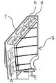
- FIG. 5 is a cross-sectional view taken along the line AA'of FIG. 2 showing a state in which the hairpin bending portion 4 is inserted into the tubular portion 7.
- a hairpin bending portion 4 protruding from one end of the laminated heat radiation fins 2 is inserted into the tubular portion 7.
- the longitudinal length L71 of the tubular portion 7 is longer than the longitudinal length L41 (height of the bending apex) of the hairpin bending portion 4. Further, the length L72 of the tubular portion 7 in the lateral direction is longer than the length L42 of the hairpin bending portion 4 in the lateral direction. Further, the length L73 of the tubular portion 7 in the depth direction is longer than the length L43 of the hairpin bending portion 4 in the depth direction.
- one hairpin bending portion 4 may be inserted into one tubular portion 7, or a plurality of hairpin bending portions 4 may be inserted into one tubular portion 7.
- FIG. 6 is a diagram showing a situation in which dew condensation water 8 is generated on the surface of the hairpin bending portion 4 in FIG.
- FIG. 7 is a diagram showing a situation in which dew condensation water 8 is generated on the surface of the hairpin bending portion 4 in FIG.
- the dew condensation water 8 is formed so as to progress the dew condensation generated at the hairpin bending portion 4 and straddle the hairpin bending portion 4 and the cylinder portion 7 through the entire hairpin bending portion 4 and the gap 9. The state of adhesion is shown.
- the adhering dew condensation water 8 causes the surface of the hairpin bending portion 4 to be bent on the outer peripheral side. Corrosion may extend to surfaces other than the above. Therefore, in the heat transfer tube 1 according to the first embodiment, the water resistant coating 10 is formed not only on the surface of the hairpin bent portion 4 on the bent outer peripheral side but also on the entire outer peripheral surface of the hairpin bent portion 4.
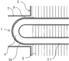
- FIG. 8 is a cross-sectional view showing a heat transfer tube 1 in which a water resistant coating 10 is formed on the entire outer peripheral surface of the hairpin bent portion 4.
- a water-resistant coating 10 is formed on the entire outer peripheral surface of the hairpin bent portion 4 in which the dew condensation water generated during the cooling / dehumidifying operation is easily held on the outer peripheral surface of the heat transfer tube 1 due to the structure of the heat exchanger 3.
- the straight pipe portion 11 on which the water resistant film 10 is not formed is inserted into the opening of the heat radiating fin 2 and is in close contact with the opening of the radiating fin 2 arranged on the side close to the hairpin bending portion 4.
- the dew condensation water 8 is suppressed from coming into contact with the straight pipe portion 11 on which the water resistant film 10 is not formed.
- the heat transfer tube 1 is suppressed from being corroded by the condensed water 8, and a more reliable air conditioner can be provided.
- Condensation water 8 generated at the hairpin bending portion 4 may move in the direction of the heat radiating fin 2 along the surface of the hairpin bending portion 4. At this time, if the opening of the heat radiating fin 2 arranged on the side close to the hairpin bending portion 4 and the straight pipe portion 11 of the heat transfer tube 1 inserted into the opening are in close contact with each other, the outer peripheral surface of the straight pipe portion 11 is contacted. Condensation does not occur and the dew condensation water 8 does not adhere.
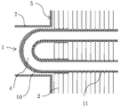
- FIG. 9 is a cross section showing a state in which the water resistant coating 10 is formed on the entire outer peripheral surface of the hairpin bent portion 4 and a part of the outer peripheral surface of the straight pipe portion 11 inserted into the opening of the heat radiation fin 2. It is a figure.
- a water resistant coating is applied to the entire outer peripheral surface of the hairpin bent portion 4 and the outer peripheral surface of the straight pipe portion 11 located in a region surrounded by two or three heat radiation fins 2 from the side close to the hairpin bent portion 4. 10 is formed.
- the area surrounded by 2 to 5 heat radiating fins 2 is not limited to the outer peripheral surface of the straight pipe portion 11 located in the area surrounded by 2 to 3 heat radiating fins 2 from the side close to the hairpin bending portion 4.
- a water resistant coating 10 may be formed on the outer peripheral surface of the straight pipe portion 11 located at.
- the condensed water 8 may adhere to the outer peripheral surface on which the water resistant coating 10 is not formed.
- the number of the fins is 5 or more, it is difficult to form a gap between the heat radiation fin 2 and the heat transfer tube 1, and the possibility that the condensed water 8 adheres to the outer peripheral surface on which the water resistant coating 10 is not formed is low, so that the effect can be obtained. No.
- Embodiment 3 A method for manufacturing a heat exchanger for an air conditioner according to the present disclosure will be described.
- the method for manufacturing a heat exchanger of an air conditioner according to the present disclosure includes a step of forming a water resistant film 10 on the outer peripheral surface of the heat transfer tube 1. After assembling the heat transfer tube 1 and the heat radiation fin 2 (after inserting the straight tube portion 11 of the heat transfer tube 1 into the opening of the heat transfer fin 2), the water resistant film 10 is formed on the hairpin bent portion 4 of the heat transfer tube 1. Is not preferable from the viewpoint of work efficiency. Therefore, it is desirable to assemble the heat transfer tube 1 and the heat radiation fin 2 by using the heat transfer tube 1 in which the water resistant film 10 is formed in advance at the corresponding portion.
- the water resistant coating 10 is formed by using a paint or a heat shrinkable tube. Since most of the steps of the method of manufacturing the heat exchanger of the air conditioner can be performed by general manufacturing equipment and manufacturing conditions, detailed description thereof will be omitted.
- the water resistant film 10 is formed as a coating film by applying a paint to the outer peripheral surface of a part of a section of the heat transfer tube 1 and drying the paint.
- a drying method for example, a method of baking at a high temperature using a furnace (so-called baking drying) may be used. Further, the temperature and time at the time of drying may be appropriately determined according to the characteristics of the applied coating material. Further, a part of the heat transfer tube 1 to which the paint is applied corresponds to the section of the hairpin bent portion 4 of the heat transfer tube 1 after the hairpin is bent. May include.
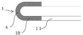
- FIG. 10 is a diagram in which a water resistant film 10 is formed on the outer peripheral surface of the hairpin bent portion 4 of the heat transfer tube 1 after the hairpin is bent.
- methods such as brush coating, roller coating, curtain coating, spray coating, and dip coating can be used.
- FIG. 11 is a diagram in which a water resistant coating 10 is formed on the outer peripheral surface of a part of the section serving as the hairpin bending portion 4 of the heat transfer tube 1 before bending the hairpin.
- a method such as brush coating, roller coating, curtain coating, or spray coating can be used.
- it is necessary to apply paint to the outer peripheral surface of a part of the linear heat transfer tube 1 before bending the hairpin to be the hairpin bending portion 4 to form the water resistant film 10.
- the resin type of the paint that forms the water-resistant coating 10 is required to have high waterproofness, withstand heat during heating operation, and not significantly deteriorate in the coexistence of copper and water. In view of these, it is preferable to use an acrylic resin-based, polyester resin-based, fluororesin-based, epoxy resin-based, or urethane resin-based paint.
- the hairpin bending portion 4 of the heat transfer tube 1 is formed by bending a part of a linear heat transfer tube 1 by 180 ° with a predetermined curvature.
- a part of the linear heat transfer tube 1 becomes a hairpin bent portion 4
- both ends of a part of the linear heat transfer tube 1 become a straight tube portion 11. That is, at the time of bending, straight pipe portions 11 connected to both ends of the hairpin bending portion 4 are formed.
- the hairpin bending step may be before or after the water resistant film forming step.
- the water-resistant coating 10 is formed by applying heat to a heat-shrinkable tube arranged on the outer peripheral surface of a part of a section of the linear heat transfer tube 1 before bending the hairpin. More specifically, first, the heat shrink tube is arranged at a position that covers the outer peripheral surface of a part of the linear heat transfer tube 1 before bending the hairpin. Here, a part of the heat transfer tube 1 corresponds to a part of the hairpin bent portion 4. Next, heat is applied to the heat-shrinkable tube to shrink and cure the heat-shrinkable tube.
- the water resistant coating 10 is formed at a position covering the outer peripheral surface of a part of the heat transfer tube 1. It is desirable to use a heat-shrinkable tube having a length longer than the length corresponding to the section of the hairpin bending portion 4, in consideration of the displacement of the heat-shrinkable tube with respect to the heat transfer tube 1 and the shrinkage of the heat-shrinkable tube. Further, as the material of the heat-shrinkable tube, it is desirable to select a material having a property of being highly waterproof, withstanding heat during heating operation, and not significantly deteriorating in the coexistence of copper and water. Further, the temperature at which the heat-shrinkable tube is contracted and cured may be appropriately determined according to the characteristics of the heat-shrinkable tube.
- the hairpin bending portion 4 of the heat transfer tube 1 is formed by bending a part of a linear heat transfer tube 1 by 180 ° with a predetermined curvature.
- a part of the linear heat transfer tube 1 becomes a hairpin bent portion 4
- both ends of a part of the linear heat transfer tube 1 become a straight tube portion 11. That is, at the time of bending, straight pipe portions 11 connected to both ends of the hairpin bending portion 4 are formed.
- the hairpin bending step is performed after the water-resistant coating forming step.
- FIG. 12 is a flowchart showing a method of manufacturing a heat exchanger of an air conditioner.
- Step 1 is a step of forming the water resistant coating 10 on the outer peripheral surface of a part of the heat transfer tube 1.
- Step 2 is a step of forming a hairpin bent portion 4 in which a part of the heat transfer tube 1 is bent at a predetermined bending ratio, and a straight tube portion 11 connected to both ends of the hairpin bent portion 4.
- the water resistant film 10 is formed by using the paint, either the step of forming the water resistant film in step 1 or the step of bending the heat transfer tube 1 in step 2 may be performed first.
- step 3 is a step of inserting the straight tube portion 11 of the heat transfer tube 1 formed through the steps of step 2 and step 1 into the opening of the heat radiation fin 2.
- step 4 the hairpin bending portion 4 of the heat transfer tube 1 that has undergone the step 3 is inserted into the insertion hole 6 of the heat exchanger fixing plate 5 and the tubular portion 7 provided on the outer peripheral edge of the insertion hole 6. This is the process of inserting.
- the heat transfer tube 1 is before the step (step 3) of inserting the straight tube portion 11 of the heat transfer tube 1 into the opening of the heat radiation fin 2.
- the step (step 2) of forming the straight pipe portion 11 connected to both ends of the portion 4 is carried out.
Landscapes
- Engineering & Computer Science (AREA)
- Mechanical Engineering (AREA)
- Physics & Mathematics (AREA)
- Thermal Sciences (AREA)
- General Engineering & Computer Science (AREA)
- Chemical & Material Sciences (AREA)
- Combustion & Propulsion (AREA)
- Heat-Exchange Devices With Radiators And Conduit Assemblies (AREA)
- Air Filters, Heat-Exchange Apparatuses, And Housings Of Air-Conditioning Units (AREA)
Priority Applications (2)
| Application Number | Priority Date | Filing Date | Title |
|---|---|---|---|
| PCT/JP2020/011200 WO2021181683A1 (ja) | 2020-03-13 | 2020-03-13 | 空気調和機の熱交換器、及び、空気調和機の熱交換器の製造方法 |
| JP2022505708A JP7352215B2 (ja) | 2020-03-13 | 2020-03-13 | 空気調和機の熱交換器、及び、空気調和機の熱交換器の製造方法 |
Applications Claiming Priority (1)
| Application Number | Priority Date | Filing Date | Title |
|---|---|---|---|
| PCT/JP2020/011200 WO2021181683A1 (ja) | 2020-03-13 | 2020-03-13 | 空気調和機の熱交換器、及び、空気調和機の熱交換器の製造方法 |
Publications (1)
| Publication Number | Publication Date |
|---|---|
| WO2021181683A1 true WO2021181683A1 (ja) | 2021-09-16 |
Family
ID=77672156
Family Applications (1)
| Application Number | Title | Priority Date | Filing Date |
|---|---|---|---|
| PCT/JP2020/011200 Ceased WO2021181683A1 (ja) | 2020-03-13 | 2020-03-13 | 空気調和機の熱交換器、及び、空気調和機の熱交換器の製造方法 |
Country Status (2)
| Country | Link |
|---|---|
| JP (1) | JP7352215B2 (https=) |
| WO (1) | WO2021181683A1 (https=) |
Cited By (2)
| Publication number | Priority date | Publication date | Assignee | Title |
|---|---|---|---|---|
| WO2023148917A1 (ja) * | 2022-02-04 | 2023-08-10 | 三菱電機株式会社 | 空気調和用熱交換器 |
| JP2024048890A (ja) * | 2022-09-28 | 2024-04-09 | ダイキン工業株式会社 | 室内熱交換器及び空気調和機 |
Citations (8)
| Publication number | Priority date | Publication date | Assignee | Title |
|---|---|---|---|---|
| JPS5825961U (ja) * | 1981-08-17 | 1983-02-18 | 三菱電機株式会社 | 冷蔵庫などの配管熱交換装置 |
| JPS6184397U (https=) * | 1984-11-05 | 1986-06-03 | ||
| JP2000026768A (ja) * | 1998-07-07 | 2000-01-25 | Mitsubishi Electric Corp | 銅の腐食防止用塗料並びにそれを用いた銅の防食法、フィンチューブ型熱交換器及び給水給湯用銅管 |
| JP2003042475A (ja) * | 2001-07-27 | 2003-02-13 | Daikin Ind Ltd | 熱交換器固定板およびそれを用いた空気調和機 |
| JP2008089230A (ja) * | 2006-10-02 | 2008-04-17 | Matsushita Electric Ind Co Ltd | フィンアンドチューブ型熱交換器 |
| JP2009192174A (ja) * | 2008-02-15 | 2009-08-27 | T Rad Co Ltd | 熱交換器の製造方法および熱交換器 |
| WO2018182036A1 (ja) * | 2017-03-31 | 2018-10-04 | ダイキン工業株式会社 | 熱交換器および空気調和装置 |
| JP2019039605A (ja) * | 2017-08-25 | 2019-03-14 | ダイキン工業株式会社 | 熱交換器 |
Family Cites Families (3)
| Publication number | Priority date | Publication date | Assignee | Title |
|---|---|---|---|---|
| JP2000297995A (ja) | 1999-04-14 | 2000-10-24 | Mitsubishi Electric Corp | 配管装置とその製造方法、熱交換器 |
| JP5029544B2 (ja) | 2008-09-09 | 2012-09-19 | ダイキン工業株式会社 | 熱交換器固定板及び空気調和機 |
| JP2015078789A (ja) | 2013-10-16 | 2015-04-23 | 三菱電機株式会社 | 熱交換器および熱交換器を備えた空気調和装置 |
-
2020
- 2020-03-13 JP JP2022505708A patent/JP7352215B2/ja active Active
- 2020-03-13 WO PCT/JP2020/011200 patent/WO2021181683A1/ja not_active Ceased
Patent Citations (8)
| Publication number | Priority date | Publication date | Assignee | Title |
|---|---|---|---|---|
| JPS5825961U (ja) * | 1981-08-17 | 1983-02-18 | 三菱電機株式会社 | 冷蔵庫などの配管熱交換装置 |
| JPS6184397U (https=) * | 1984-11-05 | 1986-06-03 | ||
| JP2000026768A (ja) * | 1998-07-07 | 2000-01-25 | Mitsubishi Electric Corp | 銅の腐食防止用塗料並びにそれを用いた銅の防食法、フィンチューブ型熱交換器及び給水給湯用銅管 |
| JP2003042475A (ja) * | 2001-07-27 | 2003-02-13 | Daikin Ind Ltd | 熱交換器固定板およびそれを用いた空気調和機 |
| JP2008089230A (ja) * | 2006-10-02 | 2008-04-17 | Matsushita Electric Ind Co Ltd | フィンアンドチューブ型熱交換器 |
| JP2009192174A (ja) * | 2008-02-15 | 2009-08-27 | T Rad Co Ltd | 熱交換器の製造方法および熱交換器 |
| WO2018182036A1 (ja) * | 2017-03-31 | 2018-10-04 | ダイキン工業株式会社 | 熱交換器および空気調和装置 |
| JP2019039605A (ja) * | 2017-08-25 | 2019-03-14 | ダイキン工業株式会社 | 熱交換器 |
Cited By (5)
| Publication number | Priority date | Publication date | Assignee | Title |
|---|---|---|---|---|
| WO2023148917A1 (ja) * | 2022-02-04 | 2023-08-10 | 三菱電機株式会社 | 空気調和用熱交換器 |
| JPWO2023148917A1 (https=) * | 2022-02-04 | 2023-08-10 | ||
| JP7706578B2 (ja) | 2022-02-04 | 2025-07-11 | 三菱電機株式会社 | 空気調和用熱交換器 |
| JP2024048890A (ja) * | 2022-09-28 | 2024-04-09 | ダイキン工業株式会社 | 室内熱交換器及び空気調和機 |
| JP7667462B2 (ja) | 2022-09-28 | 2025-04-23 | ダイキン工業株式会社 | 室内熱交換器及び空気調和機 |
Also Published As
| Publication number | Publication date |
|---|---|
| JPWO2021181683A1 (https=) | 2021-09-16 |
| JP7352215B2 (ja) | 2023-09-28 |
Similar Documents
| Publication | Publication Date | Title |
|---|---|---|
| US6918435B2 (en) | Fluid to gas heat exchangers | |
| US9251947B2 (en) | Liquid cooling arrangement of an inductive component and a method for manufacturing an inductive component | |
| WO2013161802A1 (ja) | 熱交換器、及び空気調和機 | |
| WO2021181683A1 (ja) | 空気調和機の熱交換器、及び、空気調和機の熱交換器の製造方法 | |
| CN106716042A (zh) | 热交换器以及热交换器的板状翅片的制造方法 | |
| US12158311B2 (en) | Fin of heat exchanger, method for manufacturing the same, heat exchanger, and air conditioning apparatus | |
| JP2004020174A (ja) | 平板形放熱フィン、それを用いた熱交換器及びその製造方法 | |
| JP2015117876A (ja) | フィン・アンド・チューブ型熱交換器 | |
| JP5944626B2 (ja) | 熱交換器の製造方法 | |
| JP2009109183A (ja) | 熱交換器用チューブ | |
| CN212658085U (zh) | 换热器 | |
| WO2014162700A1 (ja) | 熱交換器の製造方法および熱交換器 | |
| JP2011257084A (ja) | オールアルミニウム熱交換器 | |
| US20250020415A1 (en) | Air conditioner | |
| US20050072562A1 (en) | Heat exchanger tube assembly | |
| JPWO2021181683A5 (https=) | ||
| CN114440666B (zh) | 微通道换热器及电器设备 | |
| US6729382B2 (en) | Condenser for vehicle air-conditioning systems | |
| CN217210509U (zh) | 微通道扁管及微通道换热器 | |
| CN104833258A (zh) | 换热器管组件及其制造方法 | |
| WO2014101215A1 (en) | Coil end plate for a heat exchanger coil assembly | |
| KR19990021468A (ko) | 핀형 응축기 및 핀형 응축기용 파이프의 밴딩방법 | |
| JP4291644B2 (ja) | 熱交換器 | |
| GB2254687A (en) | Heat exchanger | |
| US20250020416A1 (en) | Air conditioner |
Legal Events
| Date | Code | Title | Description |
|---|---|---|---|
| 121 | Ep: the epo has been informed by wipo that ep was designated in this application |
Ref document number: 20924328 Country of ref document: EP Kind code of ref document: A1 |
|
| ENP | Entry into the national phase |
Ref document number: 2022505708 Country of ref document: JP Kind code of ref document: A |
|
| NENP | Non-entry into the national phase |
Ref country code: DE |
|
| 122 | Ep: pct application non-entry in european phase |
Ref document number: 20924328 Country of ref document: EP Kind code of ref document: A1 |