WO2021181653A1 - エレベーターのドアパネル構造 - Google Patents
エレベーターのドアパネル構造 Download PDFInfo
- Publication number
- WO2021181653A1 WO2021181653A1 PCT/JP2020/011044 JP2020011044W WO2021181653A1 WO 2021181653 A1 WO2021181653 A1 WO 2021181653A1 JP 2020011044 W JP2020011044 W JP 2020011044W WO 2021181653 A1 WO2021181653 A1 WO 2021181653A1
- Authority
- WO
- WIPO (PCT)
- Prior art keywords
- joint
- end portion
- joint end
- door panel
- reinforcing member
- Prior art date
- Legal status (The legal status is an assumption and is not a legal conclusion. Google has not performed a legal analysis and makes no representation as to the accuracy of the status listed.)
- Ceased
Links
Images


Classifications
-
- B—PERFORMING OPERATIONS; TRANSPORTING
- B66—HOISTING; LIFTING; HAULING
- B66B—ELEVATORS; ESCALATORS OR MOVING WALKWAYS
- B66B13/00—Doors, gates, or other apparatus controlling access to, or exit from, cages or lift well landings
- B66B13/30—Constructional features of doors or gates
Definitions
- This disclosure relates to the elevator door panel structure.
- Patent Document 1 discloses an elevator door panel structure in which a front plate of an elevator door panel and a reinforcing member are joined by an adhesive.
- An object of the present disclosure is to provide an elevator door panel structure capable of achieving both sufficient strength and high design.
- the door panel structure of the elevator includes a front plate of a door panel provided on a car door or a landing door of an elevator, and a reinforcing member having a first length in the longitudinal direction and provided so as to overlap the front plate.
- the door panel structure of the elevator includes a joint weld formed by laser welding.
- the joint welded portion includes a first joint end portion and a joint central portion. Therefore, the door panel structure of the elevator can achieve both sufficient strength and high design.
- FIG. 5 is a sectional view taken along the line AA of the door panel of the elevator according to the first embodiment. It is an X arrow view of the door panel of the elevator in Embodiment 1. FIG. It is an X arrow view of the door panel of the elevator in Embodiment 2.
- FIG. 5 is a sectional view taken along the line AA of the door panel of the elevator according to the first embodiment. It is an X arrow view of the door panel of the elevator in Embodiment 1.
- FIG. It is an X arrow view of the door panel of the elevator in Embodiment 2.
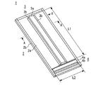
- FIG. 1 is a perspective view of an elevator door panel according to the first embodiment.
- the door panel 1 includes a front plate 2, a reinforcing member 3, and a lower reinforcing member 4.
- the door panel 1 is provided on the landing door of an elevator (not shown).
- the door panel 1 is provided on an elevator car door (not shown).
- the front plate 2 is made of a steel plate material.
- the front plate 2 is molded by bending each side of the steel plate material.
- the front plate 2 is provided with a back surface 2a on one side.
- the front plate 2 is provided with a design surface 2b on the other side.
- the back surface 2a is the side surface of the front plate 2 surrounded by each side of the bent steel plate material.
- the back surface 2a is a side surface that cannot be seen by the user at the landing when the door panel 1 is installed on the landing door.
- the design surface 2b is the opposite side surface of the back surface 2a.
- the design surface 2b is a side surface that can be seen by a user at the landing when the door panel 1 is installed on the landing door.
- the design surface 2b is painted with a design property.
- the design surface 2b is processed to have a design property.
- the reinforcing member 3 is made of a steel plate material.
- the reinforcing member 3 is created by bending a steel plate material.
- the reinforcing member 3 is molded so that the cross section has a hat-shaped shape.
- the reinforcing member 3 has a first length L1 in the longitudinal direction.
- the reinforcing member 3 includes a top plate portion 3a and two flange portions 3b.
- the reinforcing member 3 is provided so as to be in contact with the front surface of the back surface 2a.
- the reinforcing member 3 is provided so as to overlap the front plate 2.
- the reinforcing member 3 is joined to the front plate 2 by laser welding.
- the lower reinforcing member 4 is made of a steel plate material.
- the lower reinforcing member 4 is created by bending a steel plate material.
- the lower reinforcing member 4 is molded so that the cross section has a hat-shaped shape.
- the lower reinforcing member 4 has a second length L2 in the long side direction.
- the lower reinforcing member 4 includes a lower top plate portion 4a and two lower flange portions 4b.
- the lower reinforcing member 4 is provided so as to be in contact with the front surface of the back surface 2a.
- the lower reinforcing member 4 is provided so as to overlap the front plate 2.
- the lower reinforcing member 4 is joined to the front plate 2 by laser welding.
- the lower reinforcing member 4 is provided so as to be located below the door panel 1 when the door panel 1 is installed on the landing door.
- FIG. 2 is a cross-sectional view taken along the line AA of the door panel of the elevator according to the first embodiment.
- the door panel 1 includes a joint welded portion 10.
- the reinforcing member 3 is joined to the back surface 2a of the front plate 2 via the joint welded portion 10.
- the lower reinforcing member 4 (not shown) is joined to the back surface 2a of the front plate 2 via the joint welded portion 10.
- the joint welded portion 10 is formed by laser welding.
- the joint welded portion 10 joins the back surface 2a and the two flange portions 3b.
- the joint welded portion 10 joins the back surface 2a and two lower flange portions 4b (not shown).
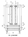
- FIG. 3 is an X arrow view of the elevator door panel according to the first embodiment.
- the shaded area is the joint welded portion 10.
- the joint welded portion 10 provided on the reinforcing member 3 includes two joint end portions 11 and a joint central portion 12.
- the two joint end portions 11 provided on the reinforcing member 3 include a first joint end portion 11a and a second joint end portion 11b.
- the first joint end portion 11a has a continuous linear shape.
- the first joint end portion 11a has the shape of a line segment perpendicular to the longitudinal direction.
- the first joint end portion 11a has a length of one half or more of the length in the width direction of the flange portion 3b.
- the first joint end portion 11a has the same length as the width direction length of the flange portion 3b.
- the first joint end portion 11a is provided above the installed door panel 1.
- the first joint end portion 11a is provided at a position separated by a distance Da in the longitudinal direction from the end portion on one side of the reinforcing member 3.
- the distance Da is a numerical value of 1/10 or less of the first length L1.
- the second joint end portion 11b has a continuous linear shape.
- the second joint end portion 11b has an arc shape.
- the second joint end portion 11b has an arc shape having a central angle of less than 360 degrees.
- the second joint end portion 11b is provided below the installed door panel 1.
- the second joint end portion 11b is provided at a position separated by a distance Db in the longitudinal direction from the other end portion of the reinforcing member 3.
- the distance Db is a numerical value of 1/10 or less of the first length L1.
- the joint central portion 12 includes a plurality of line segments arranged in a straight line.
- the joint central portion 12 has a broken line shape.
- the joint central portion 12 is formed by intermittently welding in one direction.
- the joint central portion 12 is provided between the first joint end portion 11a and the second joint end portion 11b.
- the joint central portion 12 is provided parallel to the longitudinal direction.
- the joint central portion 12 is provided at the center of the flange portion 3b in the width direction.
- the joint central portion 12 is provided on the top plate portion 3a side of the flange portion 3b in the width direction.
- the joint central portion 12 is provided so as not to overlap with the first joint end portion 11a.
- the joint central portion 12 is provided so as not to overlap with the second joint end portion 11b.
- the lower joint welded portion 20 provided on the lower reinforcing member 4 includes two lower joint end portions 21 and a lower joint central portion 22.
- each of the two lower joint end portions 21 has the same shape as the second joint end portion 11b.
- each of the two lower joint ends 21 has an arc shape.
- each of the two lower joint ends 21 has an arc shape with a central angle of less than 360 degrees.
- Each of the two lower joint end portions 21 is provided at a position separated by a distance Dc in the longitudinal direction from each end portion of the lower reinforcing member 4.
- the distance Dc is a numerical value of 1/10 or less of the second length L2.
- the lower joint central portion 22 includes a plurality of line segments arranged in a straight line.
- the lower joint central portion 22 has a broken line shape.
- the lower joint central portion 22 is formed by intermittently welding in one direction.
- the lower joint central portion 22 is provided between the two lower joint end portions 21.
- the lower joint central portion 22 is provided parallel to the longitudinal direction.
- the lower joint central portion 22 is provided at the center of the lower flange portion 4b in the width direction.
- the lower joint central portion 22 is provided on the lower top plate portion 4a side of the lower flange portion 4b in the width direction.
- the lower joint central portion 22 is provided so as not to overlap each of the two lower joint end portions 21.
- the door panel 1 of the elevator includes a front plate 2, a reinforcing member 3, and a joint welded portion 10.
- the front plate 2 is joined to the reinforcing member 3 via a joint welded portion 10 by laser welding.
- the joint welded portion 10 includes a first joint end portion 11a and a joint central portion 12.
- the first joint end portion 11a is provided within a range within a distance of 1/10 of the length L1 from one end portion of the reinforcing member 3.
- the first joint end portion 11a has a linear shape. Therefore, the reinforcing member 3 is welded to the front plate 2 at the first joint end portion 11a in a state where sufficient joint strength is secured.
- the joint central portion 12 is provided so as not to overlap with the first joint end portion 11a.
- the joint central portion 12 has a shape of a broken line parallel to the longitudinal direction of the reinforcing member 3. Therefore, the welding strain of the joint portion of the joint central portion 12 is suppressed. Therefore, the front plate 2 can be provided with a high degree of design. As a result, the door panel 1 of the elevator can have both sufficient strength and high design.
- first joint end portion 11a has a shape of a line segment perpendicular to the longitudinal direction. Therefore, on the design surface 2b, the formation of welding marks by the first joint end portion 11a is suppressed.
- the reinforcing member 3 is welded to the front plate 2 at the first joint end portion 11a in a state where sufficient joint strength is secured. As a result, the door panel 1 can achieve both sufficient strength and high design.
- the first joint end portion 11a may have the same shape as the second joint end portion 11b.
- the first joint end portion 11a has an arc shape.
- the first joint end portion 11a has an arc shape having a central angle of less than 360 degrees. Therefore, the reinforcing member 3 can be joined to the front plate 2 at the first joint end portion 11a in a state where sufficient joint strength is secured.
- the joint welded portion 10 includes a second joint end portion 11b.
- the second joint end portion 11b is provided within a range within a distance of 1/10 of the length L1 from the other end portion of the reinforcing member 3.
- the second joint end portion 11b has a linear shape. Therefore, the reinforcing member 3 can be joined to the front plate 2 at the second joint end portion 11b in a state where sufficient joint strength is secured.
- the second joint end portion 11b has an arc shape. Therefore, the reinforcing member 3 can be joined to the front plate 2 at the second joint end portion 11b in a state where sufficient joint strength is secured.
- the second joint end portion 11b may have the same shape as the first joint end portion 11a.
- the second joint end portion 11b has the shape of a line segment perpendicular to the longitudinal direction.
- the second joint end portion 11b has a length of one half or more of the length in the width direction of the flange portion 3b.
- the second joint end portion 11b has the same length as the width direction length of the flange portion 3b. Therefore, on the design surface 2b, the second joint end portion 11b can suppress the formation of welding marks.
- the one or more lower joint end portions 21 provided on the lower reinforcing member 4 may have the same shape as the first joint end portion 11a.
- one or more lower joint ends 21 have the shape of a line segment perpendicular to the longitudinal direction.
- one or more lower joint end portions 21 have a length of one half or more of the length in the width direction of the lower flange portion 4b.
- one or more lower joint end portions 21 have the same length as the widthwise length of the lower flange portion 4b. That is, the two lower joint end portions 21 substantially include a first joint end portion 11a and a second joint end portion 11b.
- FIG. 4 is an X arrow view of the elevator door panel according to the second embodiment.
- the same or corresponding parts as those of the first embodiment are designated by the same reference numerals. The explanation of the relevant part is omitted.
- the first joint end portion 11a has an elliptical shape.
- the first joint end portion 11a has an elliptical shape.
- the first joint end portion 11a has an elliptical shape having a major axis having a length of at least half the length of the flange portion 3b in the width direction.
- the first joint end portion 11a has an elliptical shape having a major axis having the same length as the width direction length of the flange portion 3b.
- the second joint end portion 11b has an elliptical shape.
- the second joint end portion 11b has an elliptical shape having a major axis having a length of at least half the length of the flange portion 3b in the width direction.
- the second joint end portion 11b has an elliptical shape having a major axis having the same length as the width direction length of the flange portion 3b.
- the first joint end portion 11a has an elliptical shape. Therefore, the reinforcing member 3 can be joined to the front plate 2 at the first joint end portion 11a in a state where sufficient joint strength is secured.
- the second joint end portion 11b has an elliptical shape. Therefore, the reinforcing member 3 can be joined to the front plate 2 at the second joint end portion 11b in a state where sufficient joint strength is secured.
- the shape provided by the second joint end portion 11b may be the shape provided by the second joint end portion 11b in the first embodiment.
- the second joint end portion 11b has an arc shape.
- the second joint end portion 11b has an arc shape having a central angle of less than 360 degrees.
- the second joint end portion 11b has the shape of a line segment perpendicular to the longitudinal direction.
- the second joint end portion 11b has a length of one half or more of the length in the width direction of the flange portion 3b.
- the second joint end portion 11b has the same length as the width direction length of the flange portion 3b.
- the shape provided by the first joint end portion 11a may be the shape provided by the first joint end portion 11a in the first embodiment.
- the first joint end portion 11a has the shape of a line segment perpendicular to the longitudinal direction.
- the first joint end portion 11a has a length of one half or more of the length in the width direction of the flange portion 3b.
- the first joint end portion 11a has the same length as the width direction length of the flange portion 3b.
- the first joint end portion 11a has an arc shape.
- the first joint end portion 11a has an arc shape having a central angle of less than 360 degrees.
- the elevator door panel structure according to the present disclosure can be used for the elevator landing door and the car door.
Landscapes
- Elevator Door Apparatuses (AREA)
Abstract
十分な強度と高い意匠性を両立することができるレーザー溶接を用いたエレベーターのドアパネル構造を提供する。エレベーターのドアパネル構造は、エレベーターのかごドアまたは乗場ドアに設けられたドアパネルの表板と、長手方向に第1長さを持ち、前記表板に重ね合うように設けられた補強部材と、前記補強部材と前記表板とをレーザー溶接により接合した接合溶接部と、を備え、前記接合溶接部は、連続した線状の形状を備え、前記補強部材の長手方向の一端部から前記第1長さの10分の1の距離以内の範囲に設けられた第1接合端部と、前記長手方向に平行な破線の形状を備え、前記第1接合端部と重ならないように設けられた接合中央部と、を備えた。
Description
本開示は、エレベーターのドアパネル構造に関する。
特許文献1は、エレベーターのドアパネルの表板と補強部材とが接着剤によって接合されたエレベーターのドアパネル構造を開示する。
しかしながら、特許文献1に記載のエレベーターのドアパネルを製作する際、接着剤が硬化する工程を製作工程に組み入れる必要がある。このため、ドアパネルの製作時間が長くなる。そこで、表板と補強部材との接合にレーザー溶接を用いる製作方法が考えられる。
しかしながら、レーザー溶接を用いてドアパネルを製作する場合、ドアパネルの十分な強度と高い意匠性とを両立することが困難である。
本開示は、上述の課題を解決するためになされた。本開示の目的は、十分な強度と高い意匠性とを両立できるエレベーターのドアパネル構造を提供することである。
本開示に係るエレベーターのドアパネル構造は、エレベーターのかごドアまたは乗場ドアに設けられたドアパネルの表板と、長手方向に第1長さを持ち、前記表板に重ね合うように設けられた補強部材と、前記補強部材と前記表板とをレーザー溶接により接合した接合溶接部と、を備え、前記接合溶接部は、連続した線状の形状を備え、前記補強部材の長手方向の一端部から前記第1長さの10分の1の距離以内の範囲に設けられた第1接合端部と、前記長手方向に平行な破線の形状を備え、前記第1接合端部と重ならないように設けられた接合中央部と、を備えた。
本開示によれば、エレベーターのドアパネル構造は、レーザー溶接によって形成された接合溶接部を備える。接合溶接部は、第1接合端部と接合中央部とを備える。このため、エレベーターのドアパネル構造は、十分な強度と高い意匠性を両立することができる。
本開示を実施するための形態について添付の図面に従って説明する。なお、各図中、同一または相当する部分には同一の符号が付される。当該部分の重複説明は適宜に簡略化ないし省略される。
実施の形態1.
図1は実施の形態1におけるエレベーターのドアパネルの斜視図である。
図1は実施の形態1におけるエレベーターのドアパネルの斜視図である。
図1に示されるように、ドアパネル1は、表板2と補強部材3と下部補強部材4とを備える。
例えば、ドアパネル1は、図示されないエレベーターの乗場ドアに設けられる。例えば、ドアパネル1は、図示されないエレベーターのかごドアに設けられる。
例えば、表板2は、鋼板材からなる。例えば、表板2は、鋼板材の各辺を折り曲げて成型される。
表板2は、一側に裏面2aを備える。表板2は、他側に意匠面2bを備える。
裏面2aは、折り曲げられた当該鋼板材の各辺に囲まれた表板2の側面である。例えば、裏面2aは、ドアパネル1を乗場ドアに設置した際、乗場にいる利用者から見えない側面である。
意匠面2bは、裏面2aの反対側面である。例えば、意匠面2bは、ドアパネル1を乗場ドアに設置した際、乗場にいる利用者から見える側面である。例えば、意匠面2bは、意匠性を持った塗装が施される。例えば、意匠面2bは、意匠性を持った加工が施される。
例えば、補強部材3は、鋼板材からなる。例えば、補強部材3は、鋼板材を折り曲げて作成される。例えば、補強部材3は、断面がハット型の形状になるよう成型される。補強部材3は、長手方向に第1長さL1を備える。
例えば、補強部材3は、天板部3aと2つのフランジ部3bとを備える。
補強部材3は、裏面2aの表面に接するように設けられる。補強部材3は、表板2に重なるように設けられる。補強部材3は、レーザー溶接によって、表板2に接合される。
例えば、下部補強部材4は、鋼板材からなる。例えば、下部補強部材4は、鋼板材を折り曲げて作成される。例えば、下部補強部材4は、断面がハット型の形状になるよう成型される。下部補強部材4は、長辺方向に第2長さL2を備える。
例えば、下部補強部材4は、下部天板部4aと2つの下部フランジ部4bとを備える。
下部補強部材4は、裏面2aの表面に接するように設けられる。下部補強部材4は、表板2に重なるように設けられる。下部補強部材4は、レーザー溶接によって、表板2に接合される。例えば、下部補強部材4は、ドアパネル1を乗場ドアに設置した際、ドアパネル1の下方に位置するように設けられる。
次に、図2を用いて、ドアパネル構造のレーザー溶接による接合溶接部10について説明する。
図2は実施の形態1におけるエレベーターのドアパネルのA-A断面図である。
図2は実施の形態1におけるエレベーターのドアパネルのA-A断面図である。
図2に示されるように、ドアパネル1は、接合溶接部10を備える。補強部材3は、接合溶接部10を介して、表板2の裏面2aと接合される。図示されない下部補強部材4は、接合溶接部10を介して、表板2の裏面2aと接合される。
接合溶接部10は、レーザー溶接によって形成される。接合溶接部10は、裏面2aと二つのフランジ部3bとを接合する。接合溶接部10は、裏面2aと図示されない二つの下部フランジ部4bとを接合する。
次に、図3を用いて、ドアパネル1の接合溶接部10について説明する。
図3は実施の形態1におけるエレベーターのドアパネルのX矢視図である。ここで、網掛けで示される領域は、接合溶接部10である。
図3は実施の形態1におけるエレベーターのドアパネルのX矢視図である。ここで、網掛けで示される領域は、接合溶接部10である。
図3に示されるように、補強部材3に設けられる接合溶接部10は、2つの接合端部11と接合中央部12とを備える。
補強部材3に設けられる2つの接合端部11は、第1接合端部11aと第2接合端部11bとを備える。
第1接合端部11aは、連続した線状の形状を備える。例えば、第1接合端部11aは、長手方向に垂直な線分の形状を備える。例えば、第1接合端部11aは、フランジ部3bの幅方向長さの2分の1以上の長さを備える。例えば、第1接合端部11aは、フランジ部3bの幅方向長さと同じ長さを備える。
第1接合端部11aは、設置されたドアパネル1の上方に設けられる。第1接合端部11aは、補強部材3の一側の端部から、長手方向に距離Daだけ離れた位置に設けられる。距離Daは、第1長さL1の10分の1以下の数値である。
第2接合端部11bは、連続した線状の形状を備える。例えば、第2接合端部11bは、円弧形状を備える。例えば、第2接合端部11bは、中心角が360度未満の円弧形状を備える。
第2接合端部11bは、設置されたドアパネル1の下方に設けられる。第2接合端部11bは、補強部材3の他側の端部から、長手方向に距離Dbだけ離れた位置に設けられる。距離Dbは、第1長さL1の10分の1以下の数値である。
接合中央部12は、一直線上に並んだ複数の線分を備える。接合中央部12は、破線形状を備える。例えば、接合中央部12は、一方向へ断続的に溶接されることで形成される。
接合中央部12は、第1接合端部11aと第2接合端部11bとの間に設けられる。接合中央部12は、長手方向に平行に設けられる。例えば、接合中央部12は、フランジ部3bの幅方向中央に設けられる。例えば、接合中央部12は、フランジ部3bの幅方向中央よりも天板部3a側に設けられる。
接合中央部12は、第1接合端部11aと重ならないように設けられる。接合中央部12は、第2接合端部11bと重ならないように設けられる。
下部補強部材4に設けられる下部接合溶接部20は、2つの下部接合端部21と下部接合中央部22とを備える。
例えば、2つの下部接合端部21の各々は、第2接合端部11bと同様の形状を備える。例えば、2つの下部接合端部21の各々は、円弧形状を備える。例えば、2つの下部接合端部21の各々は、中心角が360度未満の円弧形状を備える。
2つの下部接合端部21の各々は、下部補強部材4の各々の端部から、長手方向に距離Dcだけ離れた位置に設けられる。距離Dcは、第2長さL2の10分の1以下の数値である。
下部接合中央部22は、一直線上に並んだ複数の線分を備える。下部接合中央部22は、破線形状を備える。例えば、下部接合中央部22は、一方向へ断続的に溶接されることで形成される。
下部接合中央部22は、2つの下部接合端部21の間に設けられる。下部接合中央部22は、長手方向に平行に設けられる。例えば、下部接合中央部22は、下部フランジ部4bの幅方向中央に設けられる。例えば、下部接合中央部22は、下部フランジ部4bの幅方向中央よりも下部天板部4a側に設けられる。
下部接合中央部22は、2つの下部接合端部21の各々と重ならないように設けられる。
以上で説明した実施の形態1によれば、エレベーターのドアパネル1は、表板2と補強部材3と接合溶接部10とを備える。表板2は、レーザー溶接によって、補強部材3と接合溶接部10を介して接合されている。接合溶接部10は、第1接合端部11aと接合中央部12とを備える。第1接合端部11aは、補強部材3の一端部から長さL1の10分の1の距離以内の範囲に設けられる。第1接合端部11aは、線状の形状を備える。このため、補強部材3は、第1接合端部11aにおいて、十分な接合強度が確保された状態で表板2に溶接接合される。また、接合中央部12は、第1接合端部11aと重ならないように設けられる。接合中央部12は、補強部材3の長手方向に平行な破線の形状を備える。このため、接合中央部12の接合部分の溶接ひずみは抑制される。従って、表板2は、高い意匠性を備えることができる。その結果、エレベーターのドアパネル1は、十分な強度と高い意匠性を両立することができる。
また、第1接合端部11aは、長手方向に垂直な線分の形状を備える。このため、意匠面2bにおいて、第1接合端部11aによる溶接痕の形成は抑制される。補強部材3は、第1接合端部11aにおいて、十分な接合強度が確保された状態で表板2に溶接接合される。その結果、ドアパネル1は、十分な強度と高い意匠性を両立することができる。
なお、第1接合端部11aは、第2接合端部11bと同じ形状を備えてもよい。例えば、第1接合端部11aは、円弧形状を備える。例えば、第1接合端部11aは、中心角が360度未満の円弧形状を備える。このため、補強部材3は、第1接合端部11aにおいて、十分な接合強度が確保された状態で表板2に接合されることができる。
また、接合溶接部10は、第2接合端部11bを備える。第2接合端部11bは、補強部材3の他端部から長さL1の10分の1の距離以内の範囲に設けられる。第2接合端部11bは、線状の形状を備える。このため、補強部材3は、第2接合端部11bにおいて、十分な接合強度が確保された状態で表板2に接合されることができる。
また、第2接合端部11bは、円弧形状を備える。このため、補強部材3は、第2接合端部11bにおいて、十分な接合強度が確保された状態で表板2に接合されることができる。
なお、第2接合端部11bは、第1接合端部11aと同じ形状を備えてもよい。例えば、第2接合端部11bは、長手方向に垂直な線分の形状を備える。例えば、第2接合端部11bは、フランジ部3bの幅方向長さの2分の1以上の長さを備える。例えば、第2接合端部11bは、フランジ部3bの幅方向長さと同じ長さを備える。このため、意匠面2bにおいて、第2接合端部11bは、溶接痕の形成を抑制することができる。
なお、下部補強部材4に設けられる1つ以上の下部接合端部21は、第1接合端部11aと同様の形状を備えてもよい。例えば、1つ以上の下部接合端部21は、長手方向に垂直な線分の形状を備える。例えば、1つ以上の下部接合端部21は、下部フランジ部4bの幅方向長さの2分の1以上の長さを備える。例えば、1つ以上の下部接合端部21は、下部フランジ部4bの幅方向長さと同じ長さを備える。即ち、2つの下部接合端部21は、実質的に第1接合端部11aと第2接合端部11bとを備えている。
実施の形態2.
図4は実施の形態2におけるエレベーターのドアパネルのX矢視図である。なお、実施の形態1の部分と同一又は相当部分には同一符号が付される。当該部分の説明は省略される。
図4は実施の形態2におけるエレベーターのドアパネルのX矢視図である。なお、実施の形態1の部分と同一又は相当部分には同一符号が付される。当該部分の説明は省略される。
図4に示されるように、例えば、第1接合端部11aは、楕円の形状を備える。第1接合端部11aは、楕円の形状を備える。例えば、第1接合端部11aは、フランジ部3bの幅方向長さの2分の1以上の長さの長軸を持つ楕円の形状を備える。例えば、第1接合端部11aは、フランジ部3bの幅方向長さと同じ長さの長軸を持つ楕円の形状を備える。
例えば、第2接合端部11bは、楕円の形状を備える。例えば、第2接合端部11bは、フランジ部3bの幅方向長さの2分の1以上の長さの長軸を持つ楕円の形状を備える。例えば、第2接合端部11bは、フランジ部3bの幅方向長さと同じ長さの長軸を持つ楕円の形状を備える。
以上で説明した実施の形態2によれば、第1接合端部11aは、楕円の形状を備える。このため、補強部材3は、第1接合端部11aにおいて、十分な接合強度を確保された状態で表板2に接合されることができる。
また、第2接合端部11bは、楕円の形状を備える。このため、補強部材3は、第2接合端部11bにおいて、十分な接合強度を確保された状態で表板2に接合されることができる。
なお、第1接合端部11aが楕円の形状を備える場合、第2接合端部11bが備える形状は、実施の形態1における第2接合端部11bが備える形状でもよい。例えば、第2接合端部11bは、円弧形状を備える。例えば、第2接合端部11bは、中心角が360度未満の円弧形状を備える。例えば、第2接合端部11bは、長手方向に垂直な線分の形状を備える。例えば、第2接合端部11bは、フランジ部3bの幅方向長さの2分の1以上の長さを備える。例えば、第2接合端部11bは、フランジ部3bの幅方向長さと同じ長さを備える。
また、第2接合端部11bが楕円の形状を備える場合、第1接合端部11aが備える形状は、実施の形態1における第1接合端部11aが備える形状でもよい。例えば、第1接合端部11aは、長手方向に垂直な線分の形状を備える。例えば、第1接合端部11aは、フランジ部3bの幅方向長さの2分の1以上の長さを備える。例えば、第1接合端部11aは、フランジ部3bの幅方向長さと同じ長さを備える。例えば、第1接合端部11aは、円弧形状を備える。例えば、第1接合端部11aは、中心角が360度未満の円弧形状を備える。
以上のように、本開示に係るエレベーターのドアパネル構造は、エレベーターの乗場ドアおよびかごドアに利用できる。
1 ドアパネル、 2 表板、 2a 裏面、 2b 意匠面、 3 補強部材、 3a 天板部、 3b フランジ部、 4 下部補強部材、 4a 下部天板部、 4b 下部フランジ部、 10 接合溶接部、 11 接合端部、 11a 第1接合端部、 11b 第2接合端部、 12 接合中央部、 20 下部接合溶接部、 21 下部接合端部、 22 下部接合中央部
Claims (8)
- エレベーターのかごドアまたは乗場ドアに設けられたドアパネルの表板と、
長手方向に第1長さを持ち、前記表板に重ね合うように設けられた補強部材と、
前記補強部材と前記表板とをレーザー溶接により接合した接合溶接部と、
を備え、
前記接合溶接部は、
連続した線状の形状を備え、前記補強部材の長手方向の一端部から前記第1長さの10分の1の距離以内の範囲に設けられた第1接合端部と、
前記長手方向に平行な破線の形状を備え、前記第1接合端部と重ならないように設けられた接合中央部と、
を備えたエレベーターのドアパネル構造。 - 前記第1接合端部は、前記長手方向に垂直な線分の形状を備えた請求項1に記載のエレベーターのドアパネル構造。
- 前記第1接合端部は、円弧形状を備えた請求項1に記載のエレベーターのドアパネル構造。
- 前記第1接合端部は、楕円の形状を備えた請求項1に記載のエレベーターのドアパネル構造。
- 前記接合溶接部は、
連続した線状の形状を備え、前記補強部材の長手方向の他端部から前記第1長さの10分の1の距離以内の範囲に設けられた第2接合端部、
を備えた請求項1から請求項4のいずれか一項に記載のエレベーターのドアパネル構造。 - 前記第2接合端部は、前記長手方向に垂直な線分の形状を備えた請求項5に記載のエレベーターのドアパネル構造。
- 前記第2接合端部は、円弧形状を備えた請求項5に記載のエレベーターのドアパネル構造。
- 前記第2接合端部は、楕円の形状を備えた請求項5に記載のエレベーターのドアパネル構造。
Priority Applications (3)
| Application Number | Priority Date | Filing Date | Title |
|---|---|---|---|
| CN202080093073.3A CN115210166B (zh) | 2020-03-13 | 2020-03-13 | 电梯的门板结构 |
| PCT/JP2020/011044 WO2021181653A1 (ja) | 2020-03-13 | 2020-03-13 | エレベーターのドアパネル構造 |
| JP2021501352A JP6901054B1 (ja) | 2020-03-13 | 2020-03-13 | エレベーターのドアパネル構造 |
Applications Claiming Priority (1)
| Application Number | Priority Date | Filing Date | Title |
|---|---|---|---|
| PCT/JP2020/011044 WO2021181653A1 (ja) | 2020-03-13 | 2020-03-13 | エレベーターのドアパネル構造 |
Publications (1)
| Publication Number | Publication Date |
|---|---|
| WO2021181653A1 true WO2021181653A1 (ja) | 2021-09-16 |
Family
ID=76753053
Family Applications (1)
| Application Number | Title | Priority Date | Filing Date |
|---|---|---|---|
| PCT/JP2020/011044 Ceased WO2021181653A1 (ja) | 2020-03-13 | 2020-03-13 | エレベーターのドアパネル構造 |
Country Status (3)
| Country | Link |
|---|---|
| JP (1) | JP6901054B1 (ja) |
| CN (1) | CN115210166B (ja) |
| WO (1) | WO2021181653A1 (ja) |
Citations (5)
| Publication number | Priority date | Publication date | Assignee | Title |
|---|---|---|---|---|
| JPS5775294A (en) * | 1980-10-28 | 1982-05-11 | Toshiba Corp | Panel of elevator cage |
| JP2000512606A (ja) * | 1996-06-26 | 2000-09-26 | コネ コーポレイション | エレベータカードアおよび乗場ドアの後化粧方法および装置 |
| WO2015182401A1 (ja) * | 2014-05-30 | 2015-12-03 | テイ・エス テック株式会社 | 骨格構造体及びその製造方法 |
| CN106808088A (zh) * | 2017-03-28 | 2017-06-09 | 广东泰格威机器人科技有限公司 | 一种镜面电梯门板与镀锌加强板的无痕焊接方法 |
| JP2019196252A (ja) * | 2018-05-10 | 2019-11-14 | 三菱電機株式会社 | エレベータの意匠パネル構造および意匠パネルのレーザー溶接方法 |
Family Cites Families (5)
| Publication number | Priority date | Publication date | Assignee | Title |
|---|---|---|---|---|
| EP0923372A4 (en) * | 1996-02-22 | 2001-09-05 | Merck & Co Inc | INHIBITORS OF PYRIDINONE THROMBIN |
| JP4844146B2 (ja) * | 2006-02-07 | 2011-12-28 | 三菱電機株式会社 | エレベータの乗場ドア装置 |
| EP2008958A4 (en) * | 2006-04-20 | 2013-01-30 | Mitsubishi Electric Corp | LIFT DOOR |
| JP4807746B2 (ja) * | 2006-08-10 | 2011-11-02 | Ykk Ap株式会社 | 建具 |
| CN103350286B (zh) * | 2013-05-24 | 2015-12-23 | 广州永日电梯有限公司 | 一种电梯门板壁板加强筋封头的焊接设备及方法 |
-
2020
- 2020-03-13 JP JP2021501352A patent/JP6901054B1/ja active Active
- 2020-03-13 CN CN202080093073.3A patent/CN115210166B/zh active Active
- 2020-03-13 WO PCT/JP2020/011044 patent/WO2021181653A1/ja not_active Ceased
Patent Citations (5)
| Publication number | Priority date | Publication date | Assignee | Title |
|---|---|---|---|---|
| JPS5775294A (en) * | 1980-10-28 | 1982-05-11 | Toshiba Corp | Panel of elevator cage |
| JP2000512606A (ja) * | 1996-06-26 | 2000-09-26 | コネ コーポレイション | エレベータカードアおよび乗場ドアの後化粧方法および装置 |
| WO2015182401A1 (ja) * | 2014-05-30 | 2015-12-03 | テイ・エス テック株式会社 | 骨格構造体及びその製造方法 |
| CN106808088A (zh) * | 2017-03-28 | 2017-06-09 | 广东泰格威机器人科技有限公司 | 一种镜面电梯门板与镀锌加强板的无痕焊接方法 |
| JP2019196252A (ja) * | 2018-05-10 | 2019-11-14 | 三菱電機株式会社 | エレベータの意匠パネル構造および意匠パネルのレーザー溶接方法 |
Also Published As
| Publication number | Publication date |
|---|---|
| CN115210166B (zh) | 2024-08-20 |
| JPWO2021181653A1 (ja) | 2021-09-16 |
| CN115210166A (zh) | 2022-10-18 |
| JP6901054B1 (ja) | 2021-07-14 |
Similar Documents
| Publication | Publication Date | Title |
|---|---|---|
| EP3257690B1 (en) | Structure for bonding press-molded article, structural article for automobile having said bonding structure, and method for manufacturing bonded article | |
| EP1911619B1 (en) | Door panel structure and method of producing the same | |
| CN103648812B (zh) | 车门窗框 | |
| WO2015190303A1 (ja) | 車体部品 | |
| JPWO2015133531A1 (ja) | 部材の接合構造体 | |
| US7055886B2 (en) | Low-profile high-strength vehicle door beam | |
| WO2019087310A1 (ja) | 構造材 | |
| KR102757869B1 (ko) | 차체 연결 구조 | |
| US10435081B2 (en) | Joining structure | |
| JP6901054B1 (ja) | エレベーターのドアパネル構造 | |
| CN107598405B (zh) | 焊接构件、变截面箱型构件和焊接方法 | |
| CN113165701B (zh) | 交叠的细长钢结构以及生产这种细长钢结构的方法 | |
| WO2022210580A1 (ja) | サスペンションアーム | |
| JP2010083214A (ja) | 鉄道車両および鉄道車両の製造方法 | |
| JP2025120809A (ja) | フロア部材の製造方法 | |
| JP2020152187A (ja) | ラダーフレーム補強構造 | |
| US20200246853A1 (en) | Method of manufacturing pipe | |
| JP6794837B2 (ja) | 車体側部構造 | |
| US10486744B2 (en) | Vehicle frame member | |
| JP6412421B2 (ja) | 鉄道車両の骨構造、骨構造アッセンブリ及び側構体 | |
| JPH04238725A (ja) | 自動車ドア用インパクトビーム | |
| KR101767769B1 (ko) | 롤포밍부재 | |
| JP5027523B2 (ja) | シャーシフレームのサイドメンバ構造 | |
| CN215475349U (zh) | 一种汽车纵梁加强板安装结构 | |
| US20230159108A1 (en) | Vehicle strengthening member |
Legal Events
| Date | Code | Title | Description |
|---|---|---|---|
| ENP | Entry into the national phase |
Ref document number: 2021501352 Country of ref document: JP Kind code of ref document: A |
|
| 121 | Ep: the epo has been informed by wipo that ep was designated in this application |
Ref document number: 20924399 Country of ref document: EP Kind code of ref document: A1 |
|
| NENP | Non-entry into the national phase |
Ref country code: DE |
|
| 122 | Ep: pct application non-entry in european phase |
Ref document number: 20924399 Country of ref document: EP Kind code of ref document: A1 |