WO2021181529A1 - リチウムイオン二次電池用電極、およびリチウムイオン二次電池 - Google Patents
リチウムイオン二次電池用電極、およびリチウムイオン二次電池 Download PDFInfo
- Publication number
- WO2021181529A1 WO2021181529A1 PCT/JP2020/010340 JP2020010340W WO2021181529A1 WO 2021181529 A1 WO2021181529 A1 WO 2021181529A1 JP 2020010340 W JP2020010340 W JP 2020010340W WO 2021181529 A1 WO2021181529 A1 WO 2021181529A1
- Authority
- WO
- WIPO (PCT)
- Prior art keywords
- electrode
- secondary battery
- ion secondary
- lithium ion
- electrolytic solution
- Prior art date
- Legal status (The legal status is an assumption and is not a legal conclusion. Google has not performed a legal analysis and makes no representation as to the accuracy of the status listed.)
- Ceased
Links
Images

Classifications
-
- H—ELECTRICITY
- H01—ELECTRIC ELEMENTS
- H01M—PROCESSES OR MEANS, e.g. BATTERIES, FOR THE DIRECT CONVERSION OF CHEMICAL ENERGY INTO ELECTRICAL ENERGY
- H01M10/00—Secondary cells; Manufacture thereof
- H01M10/05—Accumulators with non-aqueous electrolyte
- H01M10/056—Accumulators with non-aqueous electrolyte characterised by the materials used as electrolytes, e.g. mixed inorganic/organic electrolytes
- H01M10/0564—Accumulators with non-aqueous electrolyte characterised by the materials used as electrolytes, e.g. mixed inorganic/organic electrolytes the electrolyte being constituted of organic materials only
- H01M10/0566—Liquid materials
- H01M10/0569—Liquid materials characterised by the solvents
-
- H—ELECTRICITY
- H01—ELECTRIC ELEMENTS
- H01M—PROCESSES OR MEANS, e.g. BATTERIES, FOR THE DIRECT CONVERSION OF CHEMICAL ENERGY INTO ELECTRICAL ENERGY
- H01M10/00—Secondary cells; Manufacture thereof
- H01M10/05—Accumulators with non-aqueous electrolyte
- H01M10/056—Accumulators with non-aqueous electrolyte characterised by the materials used as electrolytes, e.g. mixed inorganic/organic electrolytes
- H01M10/0561—Accumulators with non-aqueous electrolyte characterised by the materials used as electrolytes, e.g. mixed inorganic/organic electrolytes the electrolyte being constituted of inorganic materials only
- H01M10/0562—Solid materials
-
- H—ELECTRICITY
- H01—ELECTRIC ELEMENTS
- H01M—PROCESSES OR MEANS, e.g. BATTERIES, FOR THE DIRECT CONVERSION OF CHEMICAL ENERGY INTO ELECTRICAL ENERGY
- H01M10/00—Secondary cells; Manufacture thereof
- H01M10/05—Accumulators with non-aqueous electrolyte
- H01M10/052—Li-accumulators
-
- H—ELECTRICITY
- H01—ELECTRIC ELEMENTS
- H01M—PROCESSES OR MEANS, e.g. BATTERIES, FOR THE DIRECT CONVERSION OF CHEMICAL ENERGY INTO ELECTRICAL ENERGY
- H01M10/00—Secondary cells; Manufacture thereof
- H01M10/05—Accumulators with non-aqueous electrolyte
- H01M10/052—Li-accumulators
- H01M10/0525—Rocking-chair batteries, i.e. batteries with lithium insertion or intercalation in both electrodes; Lithium-ion batteries
-
- H—ELECTRICITY
- H01—ELECTRIC ELEMENTS
- H01M—PROCESSES OR MEANS, e.g. BATTERIES, FOR THE DIRECT CONVERSION OF CHEMICAL ENERGY INTO ELECTRICAL ENERGY
- H01M4/00—Electrodes
- H01M4/02—Electrodes composed of, or comprising, active material
- H01M4/13—Electrodes for accumulators with non-aqueous electrolyte, e.g. for lithium-accumulators; Processes of manufacture thereof
-
- H—ELECTRICITY
- H01—ELECTRIC ELEMENTS
- H01M—PROCESSES OR MEANS, e.g. BATTERIES, FOR THE DIRECT CONVERSION OF CHEMICAL ENERGY INTO ELECTRICAL ENERGY
- H01M4/00—Electrodes
- H01M4/02—Electrodes composed of, or comprising, active material
- H01M4/13—Electrodes for accumulators with non-aqueous electrolyte, e.g. for lithium-accumulators; Processes of manufacture thereof
- H01M4/131—Electrodes based on mixed oxides or hydroxides, or on mixtures of oxides or hydroxides, e.g. LiCoOx
-
- H—ELECTRICITY
- H01—ELECTRIC ELEMENTS
- H01M—PROCESSES OR MEANS, e.g. BATTERIES, FOR THE DIRECT CONVERSION OF CHEMICAL ENERGY INTO ELECTRICAL ENERGY
- H01M4/00—Electrodes
- H01M4/02—Electrodes composed of, or comprising, active material
- H01M4/36—Selection of substances as active materials, active masses, active liquids
- H01M4/362—Composites
- H01M4/366—Composites as layered products
-
- H—ELECTRICITY
- H01—ELECTRIC ELEMENTS
- H01M—PROCESSES OR MEANS, e.g. BATTERIES, FOR THE DIRECT CONVERSION OF CHEMICAL ENERGY INTO ELECTRICAL ENERGY
- H01M4/00—Electrodes
- H01M4/02—Electrodes composed of, or comprising, active material
- H01M4/36—Selection of substances as active materials, active masses, active liquids
- H01M4/48—Selection of substances as active materials, active masses, active liquids of inorganic oxides or hydroxides
- H01M4/485—Selection of substances as active materials, active masses, active liquids of inorganic oxides or hydroxides of mixed oxides or hydroxides for inserting or intercalating light metals, e.g. LiTi2O4 or LiTi2OxFy
-
- H—ELECTRICITY
- H01—ELECTRIC ELEMENTS
- H01M—PROCESSES OR MEANS, e.g. BATTERIES, FOR THE DIRECT CONVERSION OF CHEMICAL ENERGY INTO ELECTRICAL ENERGY
- H01M4/00—Electrodes
- H01M4/02—Electrodes composed of, or comprising, active material
- H01M4/36—Selection of substances as active materials, active masses, active liquids
- H01M4/48—Selection of substances as active materials, active masses, active liquids of inorganic oxides or hydroxides
- H01M4/52—Selection of substances as active materials, active masses, active liquids of inorganic oxides or hydroxides of nickel, cobalt or iron
- H01M4/525—Selection of substances as active materials, active masses, active liquids of inorganic oxides or hydroxides of nickel, cobalt or iron of mixed oxides or hydroxides containing iron, cobalt or nickel for inserting or intercalating light metals, e.g. LiNiO2, LiCoO2 or LiCoOxFy
-
- H—ELECTRICITY
- H01—ELECTRIC ELEMENTS
- H01M—PROCESSES OR MEANS, e.g. BATTERIES, FOR THE DIRECT CONVERSION OF CHEMICAL ENERGY INTO ELECTRICAL ENERGY
- H01M4/00—Electrodes
- H01M4/02—Electrodes composed of, or comprising, active material
- H01M4/36—Selection of substances as active materials, active masses, active liquids
- H01M4/58—Selection of substances as active materials, active masses, active liquids of inorganic compounds other than oxides or hydroxides, e.g. sulfides, selenides, tellurides, halogenides or LiCoFy; of polyanionic structures, e.g. phosphates, silicates or borates
- H01M4/5825—Oxygenated metallic salts or polyanionic structures, e.g. borates, phosphates, silicates, olivines
-
- H—ELECTRICITY
- H01—ELECTRIC ELEMENTS
- H01M—PROCESSES OR MEANS, e.g. BATTERIES, FOR THE DIRECT CONVERSION OF CHEMICAL ENERGY INTO ELECTRICAL ENERGY
- H01M4/00—Electrodes
- H01M4/02—Electrodes composed of, or comprising, active material
- H01M4/62—Selection of inactive substances as ingredients for active masses, e.g. binders, fillers
-
- H—ELECTRICITY
- H01—ELECTRIC ELEMENTS
- H01M—PROCESSES OR MEANS, e.g. BATTERIES, FOR THE DIRECT CONVERSION OF CHEMICAL ENERGY INTO ELECTRICAL ENERGY
- H01M4/00—Electrodes
- H01M4/02—Electrodes composed of, or comprising, active material
- H01M2004/021—Physical characteristics, e.g. porosity, surface area
-
- H—ELECTRICITY
- H01—ELECTRIC ELEMENTS
- H01M—PROCESSES OR MEANS, e.g. BATTERIES, FOR THE DIRECT CONVERSION OF CHEMICAL ENERGY INTO ELECTRICAL ENERGY
- H01M2300/00—Electrolytes
- H01M2300/0017—Non-aqueous electrolytes
- H01M2300/0065—Solid electrolytes
- H01M2300/0068—Solid electrolytes inorganic
- H01M2300/0071—Oxides
-
- Y—GENERAL TAGGING OF NEW TECHNOLOGICAL DEVELOPMENTS; GENERAL TAGGING OF CROSS-SECTIONAL TECHNOLOGIES SPANNING OVER SEVERAL SECTIONS OF THE IPC; TECHNICAL SUBJECTS COVERED BY FORMER USPC CROSS-REFERENCE ART COLLECTIONS [XRACs] AND DIGESTS
- Y02—TECHNOLOGIES OR APPLICATIONS FOR MITIGATION OR ADAPTATION AGAINST CLIMATE CHANGE
- Y02E—REDUCTION OF GREENHOUSE GAS [GHG] EMISSIONS, RELATED TO ENERGY GENERATION, TRANSMISSION OR DISTRIBUTION
- Y02E60/00—Enabling technologies; Technologies with a potential or indirect contribution to GHG emissions mitigation
- Y02E60/10—Energy storage using batteries
Definitions
- the present invention relates to an electrode for a lithium ion secondary battery and a lithium ion secondary battery using the electrode.
- a lithium ion secondary battery using a liquid as an electrolyte has a structure in which a separator is present between a positive electrode and a negative electrode and is filled with a liquid electrolyte (electrolyte solution).
- the present invention has been made in view of the above background technology, and even when a positive electrode active material containing a high proportion of Ni is used, a battery having a high volumetric energy density can be used without deteriorating thermal stability. It is an object of the present invention to provide an electrode for a lithium ion secondary battery and a lithium ion secondary battery using the positive electrode, which can be realized.
- the present inventors have conducted diligent studies and found that the above problems can be solved if the electrolytic solution and the highly dielectric solid particles are present in the electrode mixture layer in a specific volume ratio, and the present invention is completed. I arrived.
- the present invention is an electrode for a lithium ion secondary battery having an electrode mixture layer containing an electrode active material, a highly dielectric oxide solid, and an electrolytic solution, and the electrolytic solution in the electrode mixture layer.
- the highly dielectric oxide solid and the electrolytic solution may be arranged in a gap between the electrode active materials.
- the electrolytic solution contains an aprotic polar solvent having a boiling point of 150 ° C. or higher, and the molar fraction A (A / B) of the aprotic polar solvent with respect to the total specific surface area B (m 2) of the highly dielectric oxide solid. ) May be 0.5 or more.
- the DSC curve of the electrode mixture layer may have a reduced exothermic peak at 270 ° C.
- the highly dielectric oxide solid may be an oxide solid electrolyte.
- the oxide solid electrolytes are Li 7 La 3 Zr 2 O 12 (LLZO), Li 6.75 La 3 Zr 1.75 Ta 0.25 O 12 (LLZTO), Li 0.33 La 0.56 TiO 3 ( LLTO), Li 1.3 Al 0.3 Ti 1.7 (PO 4 ) 3 (LATP), and Li 1.6 Al 0.6 Ge 1.4 (PO 4 ) 3 (LAGP) selected from the group It may be at least one kind.
- the volume filling rate of the electrode active material may be 60% or more with respect to the total volume of the electrode mixture constituting the electrode.
- the thickness of the electrode mixture layer may be 40 ⁇ m or more.
- the electrode for the lithium ion secondary battery may be a positive electrode.
- the electrode for the lithium ion secondary battery may be a negative electrode.
- Another invention of the present invention is a lithium ion secondary battery including the above-mentioned electrode for a lithium ion secondary battery and an electrolytic solution.
- a battery having a high volumetric energy density can be realized without deteriorating the thermal stability even when a positive electrode active material containing a high proportion of Ni is used. be able to.
- the electrode for a lithium ion secondary battery of the present invention has an electrode mixture layer containing an electrode active material, a highly dielectric oxide solid, and an electrolytic solution, and has high dielectric property with the electrolytic solution in the electrode mixture layer.
- the volume ratio with the oxide solid is in the range of 99: 1 to 76:24.
- the electrode for a lithium ion secondary battery of the present invention may be a positive electrode for a lithium ion secondary battery or a negative electrode for a lithium ion secondary battery, but a positive electrode active material containing a high proportion of Ni was used. It is preferable to apply it to the positive electrode because the effect can be more enjoyed in some cases.
- the configuration of the electrode for a lithium ion secondary battery of the present invention is not particularly limited, but for example, from an electrode mixture containing an electrode active material and a highly dielectric oxide solid in an electrode current collector.
- the electrode mixture layer is laminated, and the electrode mixture layer is impregnated with an electrolytic solution.
- the electrode current collector in the electrode for the lithium ion secondary battery of the present invention is not particularly limited, and a known current collector used in the lithium ion secondary battery can be used.
- Examples of the material of the positive electrode current collector include metal materials such as SUS, Ni, Cr, Au, Pt, Al, Fe, Ti, Zn, and Cu.
- Examples of the material of the negative electrode current collector include SUS, Ni, Cu, Ti, Al, calcined carbon, conductive polymer, conductive glass, Al—Cd alloy and the like.
- the shape of the electrode current collector for example, a foil shape, a plate shape, a mesh shape, or the like can be mentioned.
- the thickness thereof is not particularly limited, and examples thereof include 1 to 20 ⁇ m, which can be appropriately selected as needed.
- the electrode mixture layer contains an electrode active material and a highly dielectric oxide solid as essential components.
- the electrode mixture layer may be formed on at least one side of the current collector, or may be formed on both sides. It can be appropriately selected depending on the type and structure of the target lithium ion secondary battery.
- the electrode mixture layer may optionally contain other components as long as it contains the electrode active material and the highly dielectric oxide solid, which are the constituent elements of the present invention, as essential components.
- the arbitrary component for example, a known component such as a conductive auxiliary agent and a binder can be mentioned.
- the volume ratio of the electrolytic solution and the highly dielectric oxide solid is in the range of 99: 1 to 76:23.
- the range of 98: 2 to 81:19 is more preferable, and the range of 97: 3 to 85:15 is particularly preferable.
- the thickness of the electrode mixture layer of the electrode for the lithium ion secondary battery of the present invention is not particularly limited, but is preferably 40 ⁇ m or more, for example.
- the thickness of the electrode mixture layer is 40 ⁇ m or more and the volume filling rate of the electrode active material is 60% or more, the obtained electrode for a lithium ion secondary battery becomes a high-density electrode. Then, the volumetric energy density of the created battery cell can reach 500 Wh / L or more.
- the electrode active material contained in the electrode for the lithium ion secondary battery of the present invention is not particularly limited as long as it can store and release lithium ions, and the electrode active material of the lithium ion secondary battery is not particularly limited. A known substance can be applied as.
- the positive electrode active material layer is not particularly limited, and for example, LiCoO 2 , LiCoO 4 , LiMn 2 Examples thereof include O 4 , LiNiO 2 , LiFePO 4 , lithium sulfide, and sulfur.
- a material that exhibits a noble potential as compared with the negative electrode may be selected from the materials that can form the electrode.
- the electrode for a lithium ion secondary battery of the present invention realizes a battery having a high volumetric energy density without deteriorating thermal stability even when a positive electrode active material containing a high proportion of Ni is used. be able to. Therefore, for example, when a positive electrode active material containing a high proportion of Ni such as LiNi 0.8 Co 0.15 Al 0.05 O 2 (NCA) is used, the effect of the present invention can be enjoyed at a high level. can.
- NCA LiNi 0.8 Co 0.15 Al 0.05 O 2
- the negative electrode active material may be, for example, metallic lithium, a lithium alloy, a metal oxide, a metal sulfide, or a metal nitride. , Carbon materials such as silicon oxide, silicon, and graphite.
- a material that exhibits a lower potential than that of the positive electrode may be selected from the materials that can form the electrode.
- the volume filling ratio of the electrode active material is preferably 60% or more with respect to the volume of the entire electrode mixture layer.
- the volume filling rate of the electrode active material is 60% or more, the ratio of the gap formed between the particles of the electrode active material is less than 40% with respect to the volume of the entire electrode mixture layer. Therefore, it can be an electrode for a lithium ion secondary battery having a small gap ratio and an electrode having a large volume energy density.
- the volume filling rate of the electrode active material is 60% or more, for example, the cell can realize a high volume energy density of 500 Wh / L or more.
- the volume filling ratio of the electrode active material with respect to the total volume of the electrode mixture constituting the electrode is more preferably 65% or more, and most preferably 70% or more.
- the highly dielectric oxide solid contained in the electrode for a lithium ion secondary battery of the present invention is not particularly limited as long as it is an oxide having high dielectric constant.
- the dielectric constant of solid particles crushed from the crystalline state changes from the original crystalline state, and the dielectric constant decreases. Therefore, as the highly dielectric oxide solid used in the present invention, it is preferable to use a powder pulverized in a state where the high dielectric state can be maintained as much as possible.
- the powder relative permittivity of the highly dielectric oxide solid used in the present invention is preferably 10 or more, and more preferably 20 or more. If the powder relative permittivity is 10 or more, an increase in internal resistance can be suppressed even when the charge / discharge cycle is repeated, and a lithium ion secondary battery having excellent durability against the charge / discharge cycle is sufficient. It becomes possible to realize.
- the "powder relative permittivity" in the present specification means a value obtained as follows. (Measuring method of powder relative permittivity) The powder is introduced into a tablet molding machine having a diameter (R) of 38 mm for measurement, and compressed using a hydraulic press so that the thickness (d) is 1 to 2 mm to form a green compact.
- the permittivity ⁇ power of the actual volume part from the obtained powder relative permittivity is 8.854 ⁇ 10-12
- the relative permittivity ⁇ air of air is 1, as shown below.
- the "powder relative permittivity ⁇ power " was calculated using the formulas (1) to (3).
- Contact area between green compact and electrode A (R / 2) 2 * ⁇ (1)
- C total ⁇ total ⁇ ⁇ 0 ⁇ (A / d) (2)
- ⁇ total ⁇ powder ⁇ D powder + ⁇ air ⁇ (1-D powder) (3)
- the particle size of the highly dielectric oxide solid is not particularly limited, but is preferably 0.01 ⁇ m or more and about 10 ⁇ m or less, which is equal to or less than the particle size of the active material. If the particle size of the highly dielectric oxide solid is too large, it hinders the improvement of the filling rate of the active material in the electrode.
- the highly dielectric oxide solid is preferably arranged in the gap between the electrode active materials.
- the gap formed between the particles of the electrode active material can be controlled by the filling rate of the electrode active material, and is related to the density of the electrode mixture layer.
- a resin binder serving as a binder, a carbon material serving as a conductive auxiliary agent for imparting electronic conductivity, or the like may be arranged in the gaps between the particles of the electrode active material.
- the electrode for the lithium ion secondary battery of the present invention suppresses the decrease in diffusion of lithium ions inside the electrode and increases the resistance. It is possible to realize an electrode that can be suppressed and has a high packing density of the electrode active material. As a result, it is possible to realize a lithium ion secondary battery in which a decrease in output due to repeated charging and discharging is suppressed even when the volumetric energy density is high and the amount of electrolytic solution held by the electrode is small.
- the permeability of the electrolytic solution is improved in the electrode for the lithium ion secondary battery of the present invention.
- the uniformity of electrolyte retention in the electrode is improved.
- the impregnation time of the electrolytic solution into the electrode can be shortened, and the productivity can be improved.
- the electrode for the lithium ion secondary battery of the present invention causes the association of lithium ions and anions by the dielectric effect. It becomes possible to suppress. As a result, for example, even when an electrolytic solution containing a high concentration of lithium salt is used, the effect of reducing resistance can be exhibited.
- the highly dielectric oxide solid in the electrode mixture paste for forming the electrode mixture layer By blending the highly dielectric oxide solid in the electrode mixture paste for forming the electrode mixture layer, it is easy to form the electrode mixture layer between the particles of the electrode active material. It becomes possible to arrange the high-dielectric oxide solid substantially uniformly over the entire electrode mixture layer. Further, if a highly dielectric oxide solid is previously adhered to a conductive auxiliary agent, a binder, or the like and then mixed with an electrode active material to prepare an electrode mixture paste, the dielectric solid can be prepared in a more uniform state. The powder can be placed in the gaps between the particles of the electrode active material.
- the highly dielectric oxide solid is not particularly limited as long as it is an oxide having a high dielectric property, but is preferably an oxide solid electrolyte. If it is an oxide solid electrolyte, inexpensive crystals can be produced, and it is excellent in electrochemical oxidation resistance and reduction resistance. Further, since the oxide solid electrolyte has a small true specific gravity, it is possible to suppress an increase in the electrode weight.
- the highly dielectric oxide solid is preferably an oxide solid electrolyte having lithium ion conductivity.
- a highly dielectric oxide solid electrolyte having lithium ion conductivity can further improve the output of the obtained lithium ion secondary battery at a low temperature.
- an electrode for a lithium ion secondary battery having excellent electrochemical oxidation resistance and reduction resistance can be produced at a relatively low cost.
- the highly dielectric oxide solid those having lithium ion conductivity are preferable, and for example, Li 7 La 3 Zr 2 O 12 (LLZO), Li 6.75 La 3 Zr 1.75 Ta 0.25 O. 12 (LLZTO), Li 0.33 La 0.56 TiO 3 (LLTO), Li 1.3 Al 0.3 Ti 1.7 (PO 4 ) 3 (LATP), and Li 1.6 Al 0.6 Ge It is more preferable that it is at least one selected from the group consisting of 1.4 (PO 4 ) 3 (LAGP).
- the blending amount of the highly dielectric oxide solid in the electrode mixture layer is preferably in the range of 0.05 to 10% by mass, preferably in the range of 0.1 to 8% by mass, based on the total mass of the electrode mixture layer. Is more preferable, and the range of 0.2 to 5% by mass is particularly preferable. If it is in the range of 0.1 to 6% by mass, both the effects of lowering the resistance and improving the durability can be obtained.
- the electrolytic solution arranged in the gap between the particles of the electrode active material is not particularly limited, and an electrolytic solution known as an electrolytic solution for the lithium ion secondary battery is used. Can be applied. Even if the electrolytic solution used when forming the secondary battery using the electrode for the lithium ion secondary battery of the present invention and the electrolytic solution arranged on the electrode for the lithium ion secondary battery of the present invention are the same. It may be different.
- solvent As the solvent used for the electrolytic solution, a solvent that forms a general non-aqueous electrolytic solution can be used.
- a solvent having a cyclic structure such as ethylene carbonate (EC) and propylene carbonate (PC) and a solvent having a chain structure such as dimethyl carbonate (DMC), ethyl methyl carbonate (EMC) and diethyl carbonate (DEC) can be mentioned.
- DMC dimethyl carbonate
- EMC ethyl methyl carbonate
- DEC diethyl carbonate
- FEC partially fluorinated fluoroethylene carbonate
- DFEC difluoroethylene carbonate
- a known additive can be blended in the electrolytic solution, and examples of the additive include vinylene carbonate (VC), vinylethylene carbonate (VEC), propane sultone (PS), and fluoroethylene carbonate (FEC). And so on.
- VC vinylene carbonate
- VEC vinylethylene carbonate
- PS propane sultone
- FEC fluoroethylene carbonate
- the electrolytic solution may contain an ionic liquid.
- the ionic liquid include pyrrolidinium, piperidinium, and imidazolium composed of quaternary ammonium cations.
- the electrode for a lithium ion secondary battery of the present invention it is desirable to use an electrolytic solution in which a solvent having a high relative permittivity such as EC or PC and a solvent such as DMC or EMC having a low viscosity are combined.
- a solvent having a high relative permittivity such as EC or PC
- a solvent such as DMC or EMC having a low viscosity By using a solvent having a high relative permittivity, the degree of dissociation of the lithium salt is improved, and the lithium salt can be used at a high concentration. Further, since the viscosity becomes high and the ionic conductivity becomes low only with a solvent having a high relative permittivity, it is necessary to appropriately mix a solvent having a low viscosity to adjust the viscosity.
- the amount of a solvent having a high relative permittivity such as EC or PC is 20% by volume or more and 40% by volume or less. More preferably, it is 25% by volume or more and 35% by volume or less.
- the electrolytic solution arranged in the gap between the particles of the electrode active material contains an aproton polar solvent having a boiling point of 150 ° C. or higher, and is high.
- the mole fraction A (A / B) of the aprotonic polar solvent with respect to the total specific surface area B (m 2) of the dielectric oxide solid is preferably 0.5 or more.
- the mole fraction A (A / B) of the aprotic polar solvent with respect to the total specific surface area B (m 2) of the highly dielectric oxide solid is more preferably 0.7 or more, and more preferably 1.0 or more. Is particularly preferred. When it is 0.5 or more, the thermal stability can be improved without lowering the ionic conductivity.
- aprotic polar solvent having a boiling point of 150 ° C. or higher examples include ethylene carbonate, propylene carbonate, fluoroethylene carbonate and the like.
- the BET specific surface area measurement is a value measured by using a Macsorb manufactured by Mountech Co., Ltd. after drying a highly dielectric oxide solid powder under reduced pressure at 100 ° C. for 12 hours.
- the lithium salt contained in the electrolytic solution arranged in the gap between the particles of the electrode active material is not particularly limited, but for example, LiPF 6 , LiBF 4 , and so on.
- LiPF 6 , LiBF 4 , and so on examples thereof include LiClO 4 , LiN (SO 2 CF 3 ), LiN (SO 2 C 2 F 5 ) 2 , LiCF 3 SO 3 and the like.
- LiPF 6 , LiBF 4 , or a mixture thereof, which have high ionic conductivity and high dissociation, are preferable.
- the concentration of the lithium salt contained in the electrolytic solution arranged in the gap between the particles of the electrode active material is in the range of 0.5 to 3.0 mol / L. If it is less than 0.5 mol / L, the ionic conductivity is low, while if it exceeds 3.0 mol / L, the viscosity is high and the ionic conductivity is low, so that the effect of the solid oxide is sufficient. It becomes difficult to obtain.
- the concentration of the lithium salt contained in the electrolytic solution arranged in the gap between the particles of the electrode active material is preferably in the range of 1.0 to 3.0 mol / L, and the output performance after durability. Most preferably, it is in the range of 1.2 to 2.2 mol / L.
- the concentration of the lithium salt in the electrolytic solution is high, the viscosity of the electrolytic solution becomes high, so that the permeability of the electrolytic solution to the electrode decreases.
- the electrode for a lithium ion secondary battery of the present invention not only the electrolytic solution but also a highly dielectric oxide solid is present in the gap formed between the particles of the electrode active material. Penetration is improved.
- the concentration of the lithium salt in the electrolytic solution is high, the association of lithium ions and anions usually occurs, so that the ionic conductivity tends to decrease.
- the electrode for a lithium ion secondary battery of the present invention not only the electrolytic solution but also a highly dielectric oxide solid is present in the gap formed between the particles of the electrode active material, so that the ionic conductivity is present. Is considered to have improved.
- the electrolytic solution arranged in the gap between the particles of the electrode active material is higher than the lithium salt concentration in the electrolytic solution applied to a normal lithium ion secondary battery.
- High concentration electrolyte can be applied. Even when a high-concentration electrolytic solution is applied, the productivity can be improved because the impregnation time of the electrolytic solution into the electrode is short, and a battery having a high initial capacity can be obtained.
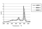
- the DSC curve of the electrode mixture layer in the electrode for the lithium ion secondary battery of the present invention is such that the exothermic peak at 270 ° C. is reduced.
- the reduction of the exothermic peak is intended to include not only the case where the peak has substantially disappeared but also the case where the peak has decreased due to the peak shift.
- heat generation due to the decomposition reaction of the electrolyte LiPF 6 and heat generation due to oxidation of the organic solvent due to deoxidation are suppressed, so that thermal stability is improved.
- the method for producing an electrode for a lithium ion secondary battery of the present invention is not particularly limited, and ordinary methods in the present technical field can be applied.
- an electrode mixture paste containing an electrode active material and a highly dielectric oxide solid as essential components is applied onto an electrode current collector, dried, rolled, and then impregnated with an electrolytic solution. ..
- the press pressure at the time of rolling it is possible to control the volume filling rate of the electrode active material (that is, the ratio of the gaps formed between the particles of the electrode active material).
- a known method can be applied as a method of applying the electrode paste to the electrode current collector.
- methods such as roller coating such as an applicator roll, screen coating, blade coating, spin coating, and bar coating can be mentioned.
- the lithium ion secondary battery of the present invention includes the electrode for the lithium ion secondary battery of the present invention and an electrolytic solution.
- the electrode for the lithium ion secondary battery of the present invention may be a positive electrode or a negative electrode, and both the positive electrode and the negative electrode are for the lithium ion secondary battery of the present invention. It may be an electrode.
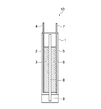
- FIG. 1 shows an embodiment of the lithium ion secondary battery of the present invention.
- the lithium ion secondary battery 10 shown in FIG. 1 has a positive electrode 4 having a positive electrode mixture layer 3 formed on the positive electrode current collector 2 and a negative electrode mixture layer 6 formed on the negative electrode current collector 5. It includes a negative electrode 7, a separator 8 that electrically insulates the positive electrode 4 and the negative electrode 7, an electrolytic solution 9, and a container 1 that houses the positive electrode 4, the negative electrode 7, the separator 8, and the electrolytic solution 9.
- the positive electrode mixture layer 3 and the negative electrode mixture layer 6 face each other with the separator 8 interposed therebetween, and the electrolytic solution 9 is stored below the positive electrode mixture layer 3 and the negative electrode mixture layer 6. There is.
- the end of the separator 8 is immersed in the electrolytic solution 9.
- the positive electrode 4 and / or the negative electrode 7 are electrodes for a lithium ion secondary battery of the present invention, and contain an electrode active material, a highly dielectric oxide solid, and an electrolytic solution, and are highly dielectric oxide solids. And the electrolytic solution are arranged in a gap formed between the particles of the electrode active material.
- the positive electrode or the negative electrode, or both the positive electrode and the negative electrode are used as the electrodes for the lithium ion secondary battery of the present invention.
- a metal, a carbon material or the like as the negative electrode active material can be used as it is as a sheet.
- the electrolytic solution applied to the lithium ion secondary battery of the present invention is not particularly limited, and a known electrolytic solution can be used as the electrolytic solution of the lithium ion secondary battery.
- the electrolytic solution used when forming the lithium ion secondary battery and the electrolytic solution arranged on the electrode for the lithium ion secondary battery of the present invention may be the same or different.
- the method for producing the lithium ion secondary battery of the present invention is not particularly limited, and ordinary methods in the present technical field can be applied.
- Example 1 [Preparation of positive electrode] Acetylene black as a conductive auxiliary agent and Li 1.3 Al 0.3 Ti 1.7 (PO 4 ) 3 (LATP) as an oxide solid electrolyte are mixed and mixed and dispersed using a rotation / revolution mixer to prepare the mixture. Obtained. Subsequently, polyvinylidene fluoride (PVDF) as a binder and LiNi 0. as a positive electrode active material were added to the obtained mixture. 8 Co 0.15 Al 0.05 O 2 (NCA) was added and dispersion treatment was carried out using a planetary mixer to obtain a mixture for a positive electrode mixture.
- PVDF polyvinylidene fluoride
- NCA Co 0.15 Al 0.05 O 2
- NMP N-methyl-2-pyrrolidone
- An aluminum foil with a thickness of 12 ⁇ m was prepared as a current collector, the prepared positive electrode mixture paste was applied to one side of the current collector, dried at 120 ° C. for 10 minutes, and then applied with a roll press at a linear pressure of 1 t / cm.
- a positive electrode for a lithium ion secondary battery was prepared by pressing and subsequently drying in a vacuum at 120 ° C. The prepared positive electrode was punched to a size of 30 mm ⁇ 40 mm and used.
- the thickness of the electrode mixture layer in the obtained positive electrode for the lithium ion secondary battery was 65 ⁇ m.
- the volume filling rate of the electrode active material with respect to the total volume of the electrode mixture was 67.4%. The measurement method is described below.
- the dry weight (grain weight) of the electrode mixture layer was measured in advance, and the electrode mixture density was determined from the electrode thickness after pressing. From the weight ratio and true specific gravity (g / cm 3 ) of each component constituting the electrode, the occupied volume of each component in the electrode mixture was obtained, and the volume ratio of the electrolytic solution and the highly dielectric oxide solid was determined. The volume filling ratio of the electrode active material with respect to the volume of the entire electrode mixture layer was calculated.
- the true specific gravity of the positive electrode active material used in this example was 4.7 g / cm 3 .
- a copper foil having a thickness of 12 ⁇ m was prepared as a current collector, the prepared negative electrode mixture paste was applied to one side of the current collector, dried at 100 ° C. for 10 minutes, and then applied with a roll press at a linear pressure of 1 t / cm.
- a negative electrode for a lithium ion secondary battery was prepared by pressing and subsequently drying in a vacuum at 100 ° C. The prepared negative electrode was punched to 34 mm ⁇ 44 mm and used.
- the thickness of the electrode mixture layer was determined by the same method as the above-mentioned positive electrode. As a result, it was 77 ⁇ m.
- a separator As a separator, a non-woven fabric (thickness 20 ⁇ m) formed into a three-layer laminate of polypropylene / polyethylene / polypropylene was prepared. The positive electrode, separator, and negative electrode prepared above were laminated and inserted into a bag-shaped aluminum laminate for secondary batteries (manufactured by Dai Nippon Printing Co., Ltd.) that was heat-sealed. As an electrolytic solution, 0.128 g (120% volume with respect to the gap volume) of a solution prepared by dissolving LiPF 6 at a volume of 1.0 mol / L in a solvent obtained by mixing ethylene carbonate and diethyl carbonate at a volume ratio of 50:50. Amount) was added to prepare a lithium ion secondary battery.
- Examples 2 to 7 In the positive electrode, the electrolytic solution arranged in the gap formed between the LATP, which is an oxide solid electrolyte, and the particles of the positive electrode active material was changed as shown in Table 1, and the same as in Example 1 was applied. To produce a lithium ion secondary battery.
- one cycle is an operation in which a constant current charge is performed at 1 C to 4.2 V in a constant temperature bath at 45 ° C. and then a constant current discharge is performed at a discharge rate of 2 C to 2.5 V. The operation was repeated for 500 cycles. After the end of 500 cycles, the constant temperature bath was set to 25 ° C. and left in a state after 2.5 V discharge for 24 hours, and then the discharge capacity after durability was measured in the same manner as the measurement of the initial discharge capacity. The results are shown in Table 1.
Landscapes
- Chemical & Material Sciences (AREA)
- General Chemical & Material Sciences (AREA)
- Chemical Kinetics & Catalysis (AREA)
- Electrochemistry (AREA)
- Engineering & Computer Science (AREA)
- Manufacturing & Machinery (AREA)
- Inorganic Chemistry (AREA)
- Materials Engineering (AREA)
- General Physics & Mathematics (AREA)
- Condensed Matter Physics & Semiconductors (AREA)
- Physics & Mathematics (AREA)
- Composite Materials (AREA)
- Crystallography & Structural Chemistry (AREA)
- Secondary Cells (AREA)
- Battery Electrode And Active Subsutance (AREA)
Abstract
Niを高い比率で含む正極活物質を用いた場合であっても、熱安定性を低下させることなく、体積エネルギー密度が高い電池を実現することのできる、リチウムイオン二次電池用電極、および当該正極を用いたリチウムイオン二次電池を提供する。 電極合材層に、電解液と高誘電性固体粒子とを特定の体積比率で存在させる。具体的には、電極活物質と、高誘電性酸化物固体と、電解液と、を含む電極合材層を有するリチウムイオン二次電池用電極とし、電極合材層における電解液と高誘電性酸化物固体との体積比率を、99:1~76:24の範囲とする。
Description
本発明は、リチウムイオン二次電池用電極、および当該電極を用いたリチウムイオン二次電池に関する。
従来、高エネルギー密度を有する二次電池として、リチウムイオン二次電池が幅広く普及している。液体を電解質として用いているリチウムイオン二次電池は、正極と負極との間にセパレータを存在させ、液体の電解質(電解液)が充填された構造を有する。
このようなリチウムイオン二次電池は、用途によって様々な要求があり、例えば、自動車等を用途とする場合には、体積エネルギー密度をさらに高める要請がある。これに対して、Ni系の正極活物質を用いる方法が提案されている(特許文献1参照)。
しかしながら、LiNi0.8Co0.15Al0.05O2(NCA)等のNiを高い比率で含む正極活物質を用いる場合には、熱安定性が低下する問題が生じていた。
本発明は上記の背景技術に鑑みてなされたものであり、Niを高い比率で含む正極活物質を用いた場合であっても、熱安定性を低下させることなく、体積エネルギー密度が高い電池を実現することのできる、リチウムイオン二次電池用電極、および当該正極を用いたリチウムイオン二次電池を提供することを目的とする。
本発明者らは鋭意検討を行い、電極合材層に、電解液と高誘電性固体粒子とを特定の体積比率で存在させれば、上記課題を解決できることを見出し、本発明を完成させるに至った。
すなわち本発明は、電極活物質と、高誘電性酸化物固体と、電解液と、を含む電極合材層を有するリチウムイオン二次電池用電極であって、電極合材層における、前記電解液と前記高誘電性酸化物固体との体積比率が99:1~76:24である、リチウムイオン二次電池用電極である。
前記高誘電性酸化物固体および前記電解液は、前記電極活物質同士の間隙に配置されていてもよい。
前記電解液は、沸点150℃以上の非プロトン性極性溶媒を含み、前記高誘電性酸化物固体の総比表面積B(m2)に対する前記非プロトン性極性溶媒のモル分率A(A/B)は、0.5以上であってもよい。
前記電極合材層のDSC曲線は、270℃の発熱ピークが減少していてもよい。
前記高誘電性酸化物固体は、酸化物固体電解質であってもよい。
前記酸化物固体電解質は、Li7La3Zr2O12(LLZO)、Li6.75La3Zr1.75Ta0.25O12(LLZTO)、Li0.33La0.56TiO3(LLTO)、Li1.3Al0.3Ti1.7(PO4)3(LATP)、およびLi1.6Al0.6Ge1.4(PO4)3(LAGP)からなる群より選ばれる少なくとも1種であってもよい。
前記電極活物質の体積充填率は、電極を構成する電極合材全体の体積に対して60%以上であってもよい。
前記電極合材層の厚みは、40μm以上であってもよい。
前記リチウムイオン二次電池用電極は、正極であってもよい。
前記リチウムイオン二次電池用電極は、負極であってもよい。
また別の本発明は、上記のリチウムイオン二次電池用電極と、電解液と、を備える、リチウムイオン二次電池である。
本発明のリチウムイオン二次電池用電極によれば、Niを高い比率で含む正極活物質を用いた場合であっても、熱安定性を低下させることなく、体積エネルギー密度が高い電池を実現することができる。
以下、本発明の実施形態について説明する。なお、本発明は以下の実施形態に限定されるものではない。
<リチウムイオン二次電池用電極>
本発明のリチウムイオン二次電池用電極は、電極活物質と、高誘電性酸化物固体と、電解液と、を含む電極合材層を有し、電極合材層における電解液と高誘電性酸化物固体との体積比率が99:1~76:24の範囲にある。
本発明のリチウムイオン二次電池用電極は、電極活物質と、高誘電性酸化物固体と、電解液と、を含む電極合材層を有し、電極合材層における電解液と高誘電性酸化物固体との体積比率が99:1~76:24の範囲にある。
本発明のリチウムイオン二次電池用電極は、リチウムイオン二次電池用正極であっても、リチウムイオン二次電池用負極であってもよいが、Niを高い比率で含む正極活物質を用いた場合に効果をより享受できることから、正極に適用するほうが好ましい。
また、本発明のリチウムイオン二次電池用電極の構成は、特に限定されるものではないが、例えば、電極集電体に、電極活物質と高誘電性酸化物固体とを含む電極合材からなる電極合材層が積層され、電極合材層に電解液が含浸された構成が挙げられる。
[集電体]
本発明のリチウムイオン二次電池用電極における電極集電体は、特に限定されるものではなく、リチウムイオン二次電池に用いられる公知の集電体を用いることができる。
本発明のリチウムイオン二次電池用電極における電極集電体は、特に限定されるものではなく、リチウムイオン二次電池に用いられる公知の集電体を用いることができる。
正極集電体の材料としては、例えば、SUS、Ni、Cr、Au、Pt、Al、Fe、Ti、Zn、Cu等の金属材料等を挙げることができる。負極集電体の材料としては、例えば、SUS、Ni、Cu、Ti、Al、焼成炭素、導電性高分子、導電性ガラス、Al-Cd合金等が挙げられる。
また、電極集電体の形状としては、例えば、箔状、板状、メッシュ状等を挙げることができる。その厚みについても特に限定されるものではなく、例えば、1~20μmが挙げられるが、必要に応じて適宜選択することができる。
[電極合材層]
本発明のリチウムイオン二次電池用電極において、電極合材層は、電極活物質と高誘電性酸化物固体とを、必須の成分として含む。電極合材層は、集電体の少なくとも片面に形成されていればよく、両面に形成されていてもよい。目的とするリチウムイオン二次電池の種類や構造によって、適宜選択することができる。
本発明のリチウムイオン二次電池用電極において、電極合材層は、電極活物質と高誘電性酸化物固体とを、必須の成分として含む。電極合材層は、集電体の少なくとも片面に形成されていればよく、両面に形成されていてもよい。目的とするリチウムイオン二次電池の種類や構造によって、適宜選択することができる。
また、電極合材層は、本発明の構成要素である電極活物質と高誘電性酸化物固体とを必須成分として含んでいれば、その他の成分を任意に含んでいてもよい。任意の成分としては、例えば、導電助剤、結着剤等の公知の成分を挙げることができる。
(電極合材層における電解液と高誘電性酸化物固体との体積比率)
本発明のリチウムイオン二次電池用電極の電極合材層において、電解液と高誘電性酸化物固体との体積比率は、99:1~76:23の範囲である。98:2~81:19の範囲であることがさらに好ましく、97:3~85:15の範囲であることが特に好ましい。
本発明のリチウムイオン二次電池用電極の電極合材層において、電解液と高誘電性酸化物固体との体積比率は、99:1~76:23の範囲である。98:2~81:19の範囲であることがさらに好ましく、97:3~85:15の範囲であることが特に好ましい。
正極に熱安定性が優れる誘電性粒子を混在させることにより、結晶構造の歪みが抑制され、N i やC o などの遷移金属の価数変動が小さくなり、活物質の結晶構造を安定化することができる。その結果、正極活物質の遷移金属の溶出や酸素の脱離が抑制され、電解液との反応を抑制されると考えられる。また、電解質LiPF6の分解反応で生じるフッ化水素を捕捉する効果により反応を抑制されると考えられる。
(電極合材層の厚み)
本発明のリチウムイオン二次電池用電極の電極合材層の厚みは、特に限定されるものではないが、例えば、40μm以上であることが好ましい。電極合材層の厚みが40μm以上であり、電極活物質の体積充填率が60%以上である場合には、得られるリチウムイオン二次電池用電極は高密度電極となる。そして、作成される電池セルの体積エネルギー密度は、500Wh/L以上にも到達可能となる。
本発明のリチウムイオン二次電池用電極の電極合材層の厚みは、特に限定されるものではないが、例えば、40μm以上であることが好ましい。電極合材層の厚みが40μm以上であり、電極活物質の体積充填率が60%以上である場合には、得られるリチウムイオン二次電池用電極は高密度電極となる。そして、作成される電池セルの体積エネルギー密度は、500Wh/L以上にも到達可能となる。
〔電極活物質〕
本発明のリチウムイオン二次電池用電極に含まれる電極活物質は、リチウムイオンを吸蔵・放出することができるものであれば、特に限定されるものではなく、リチウムイオン二次電池の電極活物質として公知の物質を適用することができる。
本発明のリチウムイオン二次電池用電極に含まれる電極活物質は、リチウムイオンを吸蔵・放出することができるものであれば、特に限定されるものではなく、リチウムイオン二次電池の電極活物質として公知の物質を適用することができる。
(正極活物質)
本発明のリチウムイオン二次電池用電極が、リチウムイオン二次電池用正極である場合には、正極活物質層としては、特に限定されるものではなく、例えば、LiCoO2、LiCoO4、LiMn2O4、LiNiO2、LiFePO4、硫化リチウム、硫黄等を挙げることができる。正極活物質としては、電極を構成できる材料から、負極と比較して貴な電位を示すものを選択すればよい。
本発明のリチウムイオン二次電池用電極が、リチウムイオン二次電池用正極である場合には、正極活物質層としては、特に限定されるものではなく、例えば、LiCoO2、LiCoO4、LiMn2O4、LiNiO2、LiFePO4、硫化リチウム、硫黄等を挙げることができる。正極活物質としては、電極を構成できる材料から、負極と比較して貴な電位を示すものを選択すればよい。
なお、本発明のリチウムイオン二次電池用電極は、Niを高い比率で含む正極活物質を用いた場合であっても、熱安定性を低下させることなく、体積エネルギー密度が高い電池を実現することができる。このため、例えば、LiNi0.8Co0.15Al0.05O2(NCA)等のNiを高い比率で含む正極活物質を用いる場合に、本発明の効果を高いレベルで享受することができる。
(負極活物質)
本発明のリチウムイオン二次電池用電極が、リチウムイオン二次電池用負極である場合には、負極活物質としては、例えば、金属リチウム、リチウム合金、金属酸化物、金属硫化物、金属窒化物、酸化シリコン、シリコン、およびグラファイト等の炭素材料等を挙げることができる。負極活物質としては、電極を構成できる材料から、正極と比較して卑な電位を示すものを選択すればよい。
本発明のリチウムイオン二次電池用電極が、リチウムイオン二次電池用負極である場合には、負極活物質としては、例えば、金属リチウム、リチウム合金、金属酸化物、金属硫化物、金属窒化物、酸化シリコン、シリコン、およびグラファイト等の炭素材料等を挙げることができる。負極活物質としては、電極を構成できる材料から、正極と比較して卑な電位を示すものを選択すればよい。
(電極活物質の体積充填率)
本発明のリチウムイオン二次電池用電極における、電極活物質の体積充填率は、電極合材層全体の体積に対して60%以上であることが好ましい。電極活物質の体積充填率が60%以上であれば、電極活物質の粒子同士の間に形成される間隙の割合は、電極合材層全体の体積に対して40%未満となる。したがって、間隙率の小さいリチウムイオン二次電池用電極となり、体積エネルギー密度が大きい電極とすることができる。電極活物質の体積充填率が60%以上の場合には、例えば、セルは500Wh/L以上という高い体積エネルギー密度を実現することができる。
本発明のリチウムイオン二次電池用電極における、電極活物質の体積充填率は、電極合材層全体の体積に対して60%以上であることが好ましい。電極活物質の体積充填率が60%以上であれば、電極活物質の粒子同士の間に形成される間隙の割合は、電極合材層全体の体積に対して40%未満となる。したがって、間隙率の小さいリチウムイオン二次電池用電極となり、体積エネルギー密度が大きい電極とすることができる。電極活物質の体積充填率が60%以上の場合には、例えば、セルは500Wh/L以上という高い体積エネルギー密度を実現することができる。
なお、本発明においては、電極を構成する電極合材全体の体積に対する電極活物質の体積充填率は、65%以上であることがさらに好ましく、70%以上であることが最も好ましい。
〔高誘電性酸化物固体〕
本発明のリチウムイオン二次電池用電極に含まれる高誘電性酸化物固体は、誘電性が高い酸化物であれば、特に限定されるものではない。通常、結晶状態から粉砕した固体粒子の誘電率は、元の結晶状態から変化し、誘電率は低下する。そこで、本発明に用いる高誘電性酸化物固体は、できるだけ高誘電状態を維持できる状態で粉砕した粉体を用いることが好ましい。
本発明のリチウムイオン二次電池用電極に含まれる高誘電性酸化物固体は、誘電性が高い酸化物であれば、特に限定されるものではない。通常、結晶状態から粉砕した固体粒子の誘電率は、元の結晶状態から変化し、誘電率は低下する。そこで、本発明に用いる高誘電性酸化物固体は、できるだけ高誘電状態を維持できる状態で粉砕した粉体を用いることが好ましい。
(粉体比誘電率)
本発明に用いる高誘電性酸化物固体の粉体比誘電率は、10以上であることが好ましく、20以上であることがさらに好ましい。粉体比誘電率が10以上であれば、充放電サイクルを繰り返したときにも内部抵抗の上昇を抑制することができ、充放電サイクルに対する優れた耐久性を有するリチウムイオン二次電池を、十分に実現することが可能となる。
本発明に用いる高誘電性酸化物固体の粉体比誘電率は、10以上であることが好ましく、20以上であることがさらに好ましい。粉体比誘電率が10以上であれば、充放電サイクルを繰り返したときにも内部抵抗の上昇を抑制することができ、充放電サイクルに対する優れた耐久性を有するリチウムイオン二次電池を、十分に実現することが可能となる。
ここで、本明細書における「粉体比誘電率」は、次のようにして求めた値をいう。
(粉体比誘電率の測定方法)
測定用の直径(R)38mmの錠剤成型器に粉体を導入し、厚み(d)が1~2mmとなるように油圧プレス機を用いて圧縮し、圧粉体を形成する。圧粉体の成形条件は、粉体の相対密度(Dpowder)=圧粉体重量密度/誘電体の真比重×100が40%以上とし、この成形体についてLCRメータを用いて自動平衡ブリッジ法にて25℃における1kHzにおける静電容量Ctotalを測定し、圧粉体比誘電率εtotalを算出する。得られた圧粉体比誘電率から実体積部の誘電率εpowerを求めるため、真空の誘電率ε0を8.854×10-12、空気の比誘電率εairを1として、下記の式(1)~(3)を用いて「粉体比誘電率εpower」を算出した。
圧粉体と電極との接触面積A=(R/2)2*π (1)
Ctotal=εtotal×ε0×(A/d) (2)
εtotal=εpowder×Dpowder+εair×(1-Dpowder) (3)
(粉体比誘電率の測定方法)
測定用の直径(R)38mmの錠剤成型器に粉体を導入し、厚み(d)が1~2mmとなるように油圧プレス機を用いて圧縮し、圧粉体を形成する。圧粉体の成形条件は、粉体の相対密度(Dpowder)=圧粉体重量密度/誘電体の真比重×100が40%以上とし、この成形体についてLCRメータを用いて自動平衡ブリッジ法にて25℃における1kHzにおける静電容量Ctotalを測定し、圧粉体比誘電率εtotalを算出する。得られた圧粉体比誘電率から実体積部の誘電率εpowerを求めるため、真空の誘電率ε0を8.854×10-12、空気の比誘電率εairを1として、下記の式(1)~(3)を用いて「粉体比誘電率εpower」を算出した。
圧粉体と電極との接触面積A=(R/2)2*π (1)
Ctotal=εtotal×ε0×(A/d) (2)
εtotal=εpowder×Dpowder+εair×(1-Dpowder) (3)
(粒子径)
高誘電性酸化物固体の粒子径は、特に限定されるものではないが、0.01μm以上で、活物質の粒子サイズ以下となる10μm以下程度であることが好ましい。高誘電性酸化物固体の粒子径が大きすぎると、電極における活物質の充填率向上の妨げとなる。
高誘電性酸化物固体の粒子径は、特に限定されるものではないが、0.01μm以上で、活物質の粒子サイズ以下となる10μm以下程度であることが好ましい。高誘電性酸化物固体の粒子径が大きすぎると、電極における活物質の充填率向上の妨げとなる。
(高誘電性酸化物固体の配置)
本発明のリチウムイオン二次電池用電極の電極合材層において、高誘電性酸化物固体は、電極活物質同士の間隙に配置されることが好ましい。電極活物質の粒子同士の間に形成される間隙は、電極活物質の充填率によって制御することができ、電極合材層の密度と関係する。なお、電極活物質の粒子同士の間隙には、結着剤となる樹脂バインダや、電子導電性を与えるための導電助剤となる炭素材等が配置されていてもよい。
本発明のリチウムイオン二次電池用電極の電極合材層において、高誘電性酸化物固体は、電極活物質同士の間隙に配置されることが好ましい。電極活物質の粒子同士の間に形成される間隙は、電極活物質の充填率によって制御することができ、電極合材層の密度と関係する。なお、電極活物質の粒子同士の間隙には、結着剤となる樹脂バインダや、電子導電性を与えるための導電助剤となる炭素材等が配置されていてもよい。
電極活物質の粒子同士の間隙に、高誘電性酸化物固体が配置されることにより、本発明のリチウムイオン二次電池用電極は、電極内部におけるリチウムイオンの拡散低下を抑制して抵抗増加を抑制でき、電極活物質の充填密度が大きい電極を実現することができる。その結果、体積エネルギー密度が高く、電極が保持する電解液量が少ない場合であっても、繰り返しの充放電による出力低下が抑制されたリチウムイオン二次電池を実現することができる。
また、電極活物質の粒子同士の間隙に、高誘電性酸化物固体が配置されることにより、本発明のリチウムイオン二次電池用電極は、電解液の浸透性が向上する。その結果、電極内における電解液保持の均一性が向上する。また、電極への電解液の含浸時間を短くすることができ、生産性を向上させることができる。
さらに、電極活物質の粒子同士の間隙に、高誘電性酸化物固体が配置されることにより、本発明のリチウムイオン二次電池用電極は、誘電効果によって、リチウムイオンと陰イオンとの会合を抑制することが可能となる。その結果、例えば、リチウム塩を高濃度に含む電解液を用いた場合であっても、抵抗を低減する効果を発現することが可能となる。
なお、高誘電性酸化物固体は、電極合材層を形成するための電極合材ペーストの中に配合しておくことで、形成される電極合材層において、電極活物質の粒子間に容易に配置することが可能となるとともに、電極合材層の全体にわたって、高誘電性酸化物固体を略均一に配置させることが容易となる。さらに、導電助剤や結着剤等に、高誘電性酸化物固体を予め付着させた後に、電極活物質と混合して電極合材ペーストを作成すれば、さらに均一な状態で、誘電性固体粉末を電極活物質の粒子同士の間隙に配置することが可能となる。
(高誘電性酸化物固体の種類)
高誘電性酸化物固体は、誘電性が高い酸化物であれば、特に限定されるものではないが、酸化物固体電解質であることが好ましい。酸化物固体電解質であれば、安価な結晶を作成でき、かつ電気化学的な耐酸化、耐還元性に優れる。また、酸化物固体電解質は真比重が小さいため、電極重量の増加を抑制することができる。
高誘電性酸化物固体は、誘電性が高い酸化物であれば、特に限定されるものではないが、酸化物固体電解質であることが好ましい。酸化物固体電解質であれば、安価な結晶を作成でき、かつ電気化学的な耐酸化、耐還元性に優れる。また、酸化物固体電解質は真比重が小さいため、電極重量の増加を抑制することができる。
さらに、高誘電性酸化物固体は、リチウムイオン伝導性を有する酸化物固体電解質であることが好ましい。リチウムイオン伝導性を有する高誘電性酸化物固体電解質であれば、得られるリチウムイオン二次電池の低温における出力を、より向上することができる。また、電気化学的な耐酸化、耐還元性に優れたリチウムイオン二次電池用電極を、比較的安価に作成することができる。
高誘電性酸化物固体としては、例えば、BaTiO3、BaxSr1-xTiO3(X=0.4~0.8)、BaZrxTi1-xO3(X=0.2~0.5)、KNbO3等のペロブスカイト型結晶構造を有する複合金属酸化物、SrBi2Ta2O9、SrBi2Nb2O9等のビスマスを含有する層状ペロブスカイト型結晶構造を有する複合金属酸化物を挙げることができる。
さらに、高誘電性酸化物固体としては、リチウムイオン伝導性を有するものが好ましく、例えば、Li7La3Zr2O12(LLZO)、Li6.75La3Zr1.75Ta0.25O12(LLZTO)、Li0.33La0.56TiO3(LLTO)、Li1.3Al0.3Ti1.7(PO4)3(LATP)、およびLi1.6Al0.6Ge1.4(PO4)3(LAGP)からなる群より選ばれる少なくとも1種であることがより好ましい。
電極合材層における高誘電性酸化物固体の配合量は、電極合材層の全質量に対し、0.05~10質量%の範囲であることが好ましく、0.1~8質量%の範囲であることがさらに好ましく、0.2~5質量%の範囲であることが、特に好ましい。0.1~6質量%の範囲であれば、低抵抗化と耐久性向上の両者の効果を得ることができる。
〔電解液〕
本発明のリチウムイオン二次電池用電極において、電極活物質の粒子同士の間隙に配置される電解液は、特に限定されるものではなく、リチウムイオン二次電池の電解液として公知の電解液を適用することができる。なお、本発明のリチウムイオン二次電池用電極を用いて二次電池を形成する際に用いる電解液と、本発明のリチウムイオン二次電池用電極に配置する電解液は、同一であっても異なっていてもよい。
本発明のリチウムイオン二次電池用電極において、電極活物質の粒子同士の間隙に配置される電解液は、特に限定されるものではなく、リチウムイオン二次電池の電解液として公知の電解液を適用することができる。なお、本発明のリチウムイオン二次電池用電極を用いて二次電池を形成する際に用いる電解液と、本発明のリチウムイオン二次電池用電極に配置する電解液は、同一であっても異なっていてもよい。
(溶媒)
電解液に用いられる溶媒としては、一般的な非水系電解液を形成する溶媒を用いることができる。例えば、エチレンカーボネート(EC)、プロピレンカーボネート(PC)等の環状構造を有する溶媒や、ジメチルカーボネート(DMC)、エチルメチルカーボネート(EMC)、ジエチルカーボネート(DEC)等の鎖状構造からなる溶媒を挙げることができる。また、一部をフッ素化した、フルオロエチレンカーボネート(FEC)、ジフルオロエチレンカーボネート(DFEC)等を用いることもできる。
電解液に用いられる溶媒としては、一般的な非水系電解液を形成する溶媒を用いることができる。例えば、エチレンカーボネート(EC)、プロピレンカーボネート(PC)等の環状構造を有する溶媒や、ジメチルカーボネート(DMC)、エチルメチルカーボネート(EMC)、ジエチルカーボネート(DEC)等の鎖状構造からなる溶媒を挙げることができる。また、一部をフッ素化した、フルオロエチレンカーボネート(FEC)、ジフルオロエチレンカーボネート(DFEC)等を用いることもできる。
また、電解液には、公知の添加剤を配合することもでき、添加剤としては、例えば、ビニレンカーボネート(VC)、ビニルエチレンカーボネート(VEC)、プロパンスルトン(PS)、フルオロエチレンカーボネート(FEC)等が挙げられる。
また、電解液として、イオン液体を含んでいてもよい。当該イオン液体としては、4級アンモニウムカチオンからなるピロリジニウム、ピペリジニウム、イミダゾリウム等が挙げられる。
本発明のリチウムイオン二次電池用電極においては、ECやPC等の比誘電率の高い溶媒と、粘度の低いDMCやEMC等の溶媒を組み合わせた電解液を用いることが望ましい。比誘電率の高い溶媒を用いることで、リチウム塩の解離度が向上し、リチウム塩を高濃度で用いることができる。また、比誘電率の高い溶媒のみでは粘度が高くなり、イオン伝導度が低くなるため、粘度の低い溶媒を適度に混合して粘度調整をする必要がある。電解液の組成としては、ECやPC等の比誘電率の高い溶媒量を、20体積%以上40体積%以下とすることが好ましい。より望ましくは、25体積%以上35体積%以下である。
本発明のリチウムイオン二次電池用電極は、電極合材層において、電極活物質の粒子同士の間隙に配置される電解液が、沸点150℃以上の非プロトン性極性溶媒を含んでおり、高誘電性酸化物固体の総比表面積B(m2)に対する非プロトン性極性溶媒のモル分率A(A/B)が、0.5以上であることが好ましい。高誘電性酸化物固体の総比表面積B(m2)に対する非プロトン性極性溶媒のモル分率A(A/B)は、0.7以上であることがさらに好ましく、1.0以上であることが特に好ましい。0.5以上であれば、イオン伝導率が低下することなく熱安定性を向上させることができる。
沸点150℃以上の非プロトン性極性溶媒としては、例えば、エチレンカーボネート、プロピレンカーボネート、フルオロエチレンカーボネート等が挙げられる。
ここで、「高誘電性酸化物固体の総比表面積B(m2)」は、BET比表面積(m2/g)×高誘電性酸化物固体の重量=高誘電性酸化物固体の総比表面積B(m2)で求めた値をいう。BET比表面積測定は、 高誘電性酸化物固体粉末を減圧下、100℃で12時間乾燥させた後、マウンテック社製Macsorbを用いて測定した値である。
(リチウム塩)
本発明のリチウムイオン二次電池用電極において、電極活物質の粒子同士の間隙に配置される電解液に含まれるリチウム塩は、特に限定されるものではないが、例えば、LiPF6、LiBF4、LiClO4、LiN(SO2CF3)、LiN(SO2C2F5)2、LiCF3SO3等を挙げることができる。これらの中では、イオン伝導度が高く、解離度も高い、LiPF6、LiBF4、あるいはこれらの混合物が好ましい。
本発明のリチウムイオン二次電池用電極において、電極活物質の粒子同士の間隙に配置される電解液に含まれるリチウム塩は、特に限定されるものではないが、例えば、LiPF6、LiBF4、LiClO4、LiN(SO2CF3)、LiN(SO2C2F5)2、LiCF3SO3等を挙げることができる。これらの中では、イオン伝導度が高く、解離度も高い、LiPF6、LiBF4、あるいはこれらの混合物が好ましい。
なお、電極活物質の粒子同士の間隙に配置される電解液に含まれるリチウム塩の濃度は、0.5~3.0mol/Lの範囲である。0.5mol/L未満の場合には、イオン伝導度が低くなり、一方で、3.0mol/Lを超える場合には、粘度が高く、イオン伝導性も低いため、固体酸化物の効果を十分得ることが困難となる。
本発明においては、電極活物質の粒子同士の間隙に配置される電解液に含まれるリチウム塩の濃度は、1.0~3.0mol/Lの範囲であることが好ましく、耐久後の出力性能を高めるためには、1.2~2.2mol/Lの範囲であることが最も好ましい。
通常、電解液におけるリチウム塩の濃度が高い場合には、電解液の粘度が高くなるため、電極への電解液の浸透性が低下する。しかしながら、本発明のリチウムイオン二次電池用電極は、電極活物質の粒子同士の間に形成される間隙に、電解液のみならず高誘電性酸化物固体が存在しているため、電解液の浸透性が向上する。
また、通常、電解液におけるリチウム塩の濃度が高い場合には、リチウムイオンと陰イオンとの会合が発生するため、イオン伝導率が低下する傾向にある。しかしながら、本発明のリチウムイオン二次電池用電極は、電極活物質の粒子同士の間に形成される間隙に、電解液のみならず高誘電性酸化物固体が存在しているため、イオン伝導率が向上したと考えられる。
このため、本発明のリチウムイオン二次電池用電極において、電極活物質の粒子同士の間隙に配置される電解液は、通常のリチウムイオン二次電池に適用される電解液におけるリチウム塩濃度よりも、高い濃度の電解液を適用することができる。高い濃度の電解液を適用した場合であっても、電極への電解液の含浸時間が短いため生産性を向上させることができ、また、初期容量の高い電池を得ることが可能となる。
〔電極合材層のDSC曲線〕
本発明のリチウムイオン二次電池用電極における電極合材層のDSC曲線は、270℃の発熱ピークが減少するものとなる。発熱ピークが減少するとは、実質的にピークが消滅している場合はもちろん、ピークシフトによって減少している場合も含む意図である。これにより、電解質LiPF6の分解反応に伴う発熱や、脱酸素による有機溶媒の酸化に伴う発熱が抑制されるため熱安定性が向上する。
本発明のリチウムイオン二次電池用電極における電極合材層のDSC曲線は、270℃の発熱ピークが減少するものとなる。発熱ピークが減少するとは、実質的にピークが消滅している場合はもちろん、ピークシフトによって減少している場合も含む意図である。これにより、電解質LiPF6の分解反応に伴う発熱や、脱酸素による有機溶媒の酸化に伴う発熱が抑制されるため熱安定性が向上する。
<リチウムイオン二次電池用電極の製造方法>
本発明のリチウムイオン二次電池用電極の製造方法は、特に限定されるものではなく、本技術分野における通常の方法を適用することができる。例えば、電極集電体上に、電極活物質と高誘電性酸化物固体を必須成分として含む電極合材ペーストを塗布し、乾燥させた後に圧延し、その後に電解液を含浸させる方法が挙げられる。このとき、圧延する際のプレス圧力を変化させることで、電極活物質の体積充填率(すなわち、電極活物質の粒子同士の間に形成される間隙の割合)を制御することが可能となる。
本発明のリチウムイオン二次電池用電極の製造方法は、特に限定されるものではなく、本技術分野における通常の方法を適用することができる。例えば、電極集電体上に、電極活物質と高誘電性酸化物固体を必須成分として含む電極合材ペーストを塗布し、乾燥させた後に圧延し、その後に電解液を含浸させる方法が挙げられる。このとき、圧延する際のプレス圧力を変化させることで、電極活物質の体積充填率(すなわち、電極活物質の粒子同士の間に形成される間隙の割合)を制御することが可能となる。
電極集電体に電極ペーストを塗布する方法としては、公知の方法を適用することができる。例えば、アプリケーターロール等のローラーコーティング、スクリーンコーティング、ブレードコーティング、スピンコーティング、バーコーティング等の方法が挙げられる。
<リチウムイオン二次電池>
本発明のリチウムイオン二次電池は、本発明のリチウムイオン二次電池用電極と、電解液と、を備える。本発明のリチウムイオン二次電池においては、本発明のリチウムイオン二次電池用電極は、正極であっても、負極であっても、正極および負極の両者ともに本発明のリチウムイオン二次電池用電極であってもよい。
本発明のリチウムイオン二次電池は、本発明のリチウムイオン二次電池用電極と、電解液と、を備える。本発明のリチウムイオン二次電池においては、本発明のリチウムイオン二次電池用電極は、正極であっても、負極であっても、正極および負極の両者ともに本発明のリチウムイオン二次電池用電極であってもよい。
図1に、本発明のリチウムイオン二次電池の一実施形態を示す。図1に示されるリチウムイオン二次電池10は、正極集電体2上に形成された正極合材層3を備える正極4と、負極集電体5上に形成された負極合材層6を備える負極7と、正極4と負極7とを電気的に絶縁するセパレータ8と、電解液9と、正極4、負極7、セパレータ8、および電解液9を収容する容器1とを備える。
容器1内で、正極合材層3と負極合材層6とはセパレータ8を挟んで対向しており、正極合材層3と負極合材層6との下方に電解液9が貯留されている。そして、セパレータ8の端部は、電解液9内に浸漬されている。正極4または負極7、あるいはその両者は、本発明のリチウムイオン二次電池用電極であり、電極活物質と、高誘電性酸化物固体と、電解液と、を含み、高誘電性酸化物固体と電解液とが電極活物質の粒子同士の間に形成される間隙に配置されている。
[正極および負極]
本発明のリチウムイオン二次電池においては、正極または負極、あるいは正極および負極の両者を、本発明のリチウムイオン二次電池用電極とする。なお、正極のみを本発明のリチウムイオン二次電池用電極とする場合には、負極としては、負極活物質となる金属や炭素材料等を、そのまま、シートとして用いることも可能である。
本発明のリチウムイオン二次電池においては、正極または負極、あるいは正極および負極の両者を、本発明のリチウムイオン二次電池用電極とする。なお、正極のみを本発明のリチウムイオン二次電池用電極とする場合には、負極としては、負極活物質となる金属や炭素材料等を、そのまま、シートとして用いることも可能である。
[電解液]
本発明のリチウムイオン二次電池に適用する電解液は、特に限定されるものではなく、リチウムイオン二次電池の電解液として公知の電解液を用いることができる。なお、リチウムイオン二次電池を形成する際に用いる電解液と、本発明のリチウムイオン二次電池用電極に配置する電解液とは、同一であっても異なっていてもよい。
本発明のリチウムイオン二次電池に適用する電解液は、特に限定されるものではなく、リチウムイオン二次電池の電解液として公知の電解液を用いることができる。なお、リチウムイオン二次電池を形成する際に用いる電解液と、本発明のリチウムイオン二次電池用電極に配置する電解液とは、同一であっても異なっていてもよい。
<リチウムイオン二次電池の製造方法>
本発明のリチウムイオン二次電池の製造方法は、特に限定されるものではなく、本技術分野における通常の方法を適用することができる。
本発明のリチウムイオン二次電池の製造方法は、特に限定されるものではなく、本技術分野における通常の方法を適用することができる。
次に、本発明を実施例等に基づいてさらに詳細に説明するが、本発明はこれに限定されるものではない。
<実施例1>
[正極の作製]
導電助剤としてアセチレンブラックと、酸化物固体電解質としてLi1.3Al0.3Ti1.7(PO4)3(LATP)とを混合し、自転公転ミキサーを用いて混合分散し、混合物を得た。続いて、得られた混合物に、結着剤としてポリフッ化ビニリデン(PVDF)と、正極活物質としてLiNi0.8Co0.15Al0.05O2(NCA)とを添加し、プラネタリーミキサーを用いて分散処理を行い、正極合材用混合物を得た。なお、正極合材用混合物における各成分の比率は、質量比で、正極活物質:LATP:導電助剤:樹脂バインダ(PVDF)=93.6:0.5:4.1:1.8となるよう混合し、すなわち、LATPの添加量が、正極合材用混合物中に0.5質量%となるよう混合した。続いて、得られた正極合材用混合物はN-メチル-2-ピロリドン(NMP)に分散させて、正極合材ペーストを作製した。
[正極の作製]
導電助剤としてアセチレンブラックと、酸化物固体電解質としてLi1.3Al0.3Ti1.7(PO4)3(LATP)とを混合し、自転公転ミキサーを用いて混合分散し、混合物を得た。続いて、得られた混合物に、結着剤としてポリフッ化ビニリデン(PVDF)と、正極活物質としてLiNi0.8Co0.15Al0.05O2(NCA)とを添加し、プラネタリーミキサーを用いて分散処理を行い、正極合材用混合物を得た。なお、正極合材用混合物における各成分の比率は、質量比で、正極活物質:LATP:導電助剤:樹脂バインダ(PVDF)=93.6:0.5:4.1:1.8となるよう混合し、すなわち、LATPの添加量が、正極合材用混合物中に0.5質量%となるよう混合した。続いて、得られた正極合材用混合物はN-メチル-2-ピロリドン(NMP)に分散させて、正極合材ペーストを作製した。
集電体として厚み12μmのアルミ箔を準備し、作製した正極合材ペーストを集電体の片面に塗布し、120℃で10分乾燥させた後、ロールプレスで1t/cmの線圧で加圧し、続いて、120℃の真空中で乾燥させることで、リチウムイオン二次電池用正極を作製した。なお、作製した正極は、30mm×40mmに打ち抜き加工して用いた。
得られたリチウムイオン二次電池用正極における電極合材層の厚みは65μmであった。また、電極合材全体の体積に対する電極活物質の体積充填率は、67.4%であった。以下に、測定方法を記載する。
(電極合材層の厚みの測定方法)
得られたリチウムイオン二次電池用正極は、集電箔と電極合材層とが一体となっている。これらの厚みを合わせてシックネスゲージで測定し、集電箔分の厚みを差し引くことで、電極合材層の厚みを求めた。
得られたリチウムイオン二次電池用正極は、集電箔と電極合材層とが一体となっている。これらの厚みを合わせてシックネスゲージで測定し、集電箔分の厚みを差し引くことで、電極合材層の厚みを求めた。
(電極合材層における電解液と高誘電性酸化物固体との体積比率、電極合材層全体の体積に対する電極活物質の体積充填率の求め方)
リチウムイオン二次電池用正極作成後、電極合材層の乾燥重量(目付重量)をあらかじめ測定し、プレス後の電極厚みより、電極の合材密度を求めた。電極を構成するそれぞれの成分の重量比と真比重(g/cm3)から、電極合材中のそれぞれの成分の占有体積を求めて、電解液と高誘電性酸化物固体との体積比率、電極合材層全体の体積に対する電極活物質の体積充填率を算出した。なお、本実施例で用いた正極活物質の真比重は、4.7g/cm3であった。
リチウムイオン二次電池用正極作成後、電極合材層の乾燥重量(目付重量)をあらかじめ測定し、プレス後の電極厚みより、電極の合材密度を求めた。電極を構成するそれぞれの成分の重量比と真比重(g/cm3)から、電極合材中のそれぞれの成分の占有体積を求めて、電解液と高誘電性酸化物固体との体積比率、電極合材層全体の体積に対する電極活物質の体積充填率を算出した。なお、本実施例で用いた正極活物質の真比重は、4.7g/cm3であった。
[負極の作製]
結着剤としてカルボキシメチルセルロースナトリウム(CMC)と、導電助剤としてアセチレンブラックとを混合し、プラネタリーミキサーを用いて分散し、混合物を得た。得られた混合物に負極活物質として人造黒鉛(AG、D50=12μm)を混合し、再度プラネタリーミキサーを用いて分散処理を実施し、負極合材用混合物を得た。続いて、得られた負極合材用混合物を、N-メチル-2-ピロリドン(NMP)に分散させ、結着剤であるスチレンブタジエンゴム(SBR)を添加して、質量比で、負極活物質:導電助剤:スチレンブタジエンゴム(SBR):結着剤(CMC)=96.5:1:1.5:1となるように負極合材ペーストを作製した。
結着剤としてカルボキシメチルセルロースナトリウム(CMC)と、導電助剤としてアセチレンブラックとを混合し、プラネタリーミキサーを用いて分散し、混合物を得た。得られた混合物に負極活物質として人造黒鉛(AG、D50=12μm)を混合し、再度プラネタリーミキサーを用いて分散処理を実施し、負極合材用混合物を得た。続いて、得られた負極合材用混合物を、N-メチル-2-ピロリドン(NMP)に分散させ、結着剤であるスチレンブタジエンゴム(SBR)を添加して、質量比で、負極活物質:導電助剤:スチレンブタジエンゴム(SBR):結着剤(CMC)=96.5:1:1.5:1となるように負極合材ペーストを作製した。
集電体として厚み12μmの銅箔を準備し、作製した負極合材ペーストを集電体の片面に塗布し、100℃で10分乾燥させた後、ロールプレスで1t/cmの線圧で加圧し、続いて、100℃の真空中で乾燥させることで、リチウムイオン二次電池用負極を作製した。なお、作製した負極は、34mm×44mmに打ち抜き加工して用いた。
得られたリチウムイオン二次電池用負極について、上記した正極と同様の方法により、電極合材層の厚みを求めた。その結果、77μmであった。
[リチウムイオン二次電池の作製]
セパレータとして、ポリプロピレン/ポリエチレン/ポリプロピレンの3層積層体となった不織布(厚み20μm)を準備した。二次電池用アルミニウムラミネート(大日本印刷製)を熱シールして袋状に加工したものの中に、上記で作製した正極、セパレータ、負極を積層して挿入した。電解液として、エチレンカーボネートとジエチルカーボネートを、体積比50:50で混合した溶媒に、LiPF6を1.0mol/Lとなるよう溶解した溶液を0.128g(間隙体積に対して120%の体積量)添加して、リチウムイオン二次電池を作製した。
セパレータとして、ポリプロピレン/ポリエチレン/ポリプロピレンの3層積層体となった不織布(厚み20μm)を準備した。二次電池用アルミニウムラミネート(大日本印刷製)を熱シールして袋状に加工したものの中に、上記で作製した正極、セパレータ、負極を積層して挿入した。電解液として、エチレンカーボネートとジエチルカーボネートを、体積比50:50で混合した溶媒に、LiPF6を1.0mol/Lとなるよう溶解した溶液を0.128g(間隙体積に対して120%の体積量)添加して、リチウムイオン二次電池を作製した。
<実施例2~7>
正極において、酸化物固体電解質であるLATPと、正極活物質の粒子同士の間に形成される間隙に配置される電解液を、表1に示すように変更した以外は、実施例1と同様にして、リチウムイオン二次電池を作製した。
正極において、酸化物固体電解質であるLATPと、正極活物質の粒子同士の間に形成される間隙に配置される電解液を、表1に示すように変更した以外は、実施例1と同様にして、リチウムイオン二次電池を作製した。
<比較例1~2>
正極において、酸化物固体電解質であるLATPを添加せず、また、正極活物質の粒子同士の間に形成される間隙に配置される電解液を、表1に示すように変更した以外は、実施例1と同様にして、リチウムイオン二次電池を作製した。
正極において、酸化物固体電解質であるLATPを添加せず、また、正極活物質の粒子同士の間に形成される間隙に配置される電解液を、表1に示すように変更した以外は、実施例1と同様にして、リチウムイオン二次電池を作製した。
<評価>
実施例および比較例で得られたリチウムイオン二次電池につき、以下の評価を行った。
実施例および比較例で得られたリチウムイオン二次電池につき、以下の評価を行った。
[初期放電容量]
作製したリチウムイオン二次電池を、測定温度(25℃)で1時間放置し、0.33Cで4.2Vまで定電流充電を行い、続けて4.2Vの電圧で定電圧充電を1時間行い、30分間放置した後、0.2Cの放電レートで2.5Vまで放電を行って、初期放電容量を測定した。結果を表1に示す。
作製したリチウムイオン二次電池を、測定温度(25℃)で1時間放置し、0.33Cで4.2Vまで定電流充電を行い、続けて4.2Vの電圧で定電圧充電を1時間行い、30分間放置した後、0.2Cの放電レートで2.5Vまで放電を行って、初期放電容量を測定した。結果を表1に示す。
[初期セル抵抗]
初期放電容量測定後のリチウムイオン二次電池を、充電レベル(SOC(State of Charge))50%に調整した。次に、Cレートを0.2Cとして10秒間パルス放電し、10秒放電時の電圧を測定した。そして、横軸を電流値、縦軸を電圧として、0.2Cにおける電流に対する10秒放電時の電圧をプロットした。次に、5分間放置後、補充電を行ってSOCを50%に復帰させた後、さらに5分間放置した。
初期放電容量測定後のリチウムイオン二次電池を、充電レベル(SOC(State of Charge))50%に調整した。次に、Cレートを0.2Cとして10秒間パルス放電し、10秒放電時の電圧を測定した。そして、横軸を電流値、縦軸を電圧として、0.2Cにおける電流に対する10秒放電時の電圧をプロットした。次に、5分間放置後、補充電を行ってSOCを50%に復帰させた後、さらに5分間放置した。
次に、上記の操作を、0.5C、1C、2C、5C、10Cの各Cレートについて行い、各Cレートにおける電流に対する10秒放電時の電圧をプロットした。そして、各プロットから得られた近似直線の傾きを本実施例で得られたリチウムイオン二次電池の初期セル抵抗とした。結果を表1に示す。
[耐久後放電容量]
充放電サイクル耐久試験として、45℃の恒温槽にて、1Cで4.2Vまで定電流充電を行った後、2Cの放電レートで2.5Vまで定電流放電を行う操作を1サイクルとし、該操作を500サイクル繰り返した。500サイクル終了後、恒温槽を25℃として2.5V放電後の状態で24時間放置し、その後、初期放電容量の測定と同様にして、耐久後の放電容量を測定した。結果を表1に示す。
充放電サイクル耐久試験として、45℃の恒温槽にて、1Cで4.2Vまで定電流充電を行った後、2Cの放電レートで2.5Vまで定電流放電を行う操作を1サイクルとし、該操作を500サイクル繰り返した。500サイクル終了後、恒温槽を25℃として2.5V放電後の状態で24時間放置し、その後、初期放電容量の測定と同様にして、耐久後の放電容量を測定した。結果を表1に示す。
[耐久後セル抵抗]
耐久後放電容量測定後のリチウムイオン二次電池を、初期セル抵抗の測定と同様に、(SOC(State of Charge))50%となるように充電を行って調整し、初期セル抵抗の測定と同様の方法で、耐久後セル抵抗を測定した。結果を表1に示す。
耐久後放電容量測定後のリチウムイオン二次電池を、初期セル抵抗の測定と同様に、(SOC(State of Charge))50%となるように充電を行って調整し、初期セル抵抗の測定と同様の方法で、耐久後セル抵抗を測定した。結果を表1に示す。
[容量維持率]
初期放電容量に対する耐久後放電容量を求め、容量維持率とした。結果を表1に示す。
初期放電容量に対する耐久後放電容量を求め、容量維持率とした。結果を表1に示す。
[セル抵抗上昇率]
初期セル抵抗に対する耐久後セル抵抗を求め、セル抵抗上昇率とした。結果を表1に示す。
初期セル抵抗に対する耐久後セル抵抗を求め、セル抵抗上昇率とした。結果を表1に示す。
[DSC測定]
初期放電容量確認後の電池を0.2Cにて4.2Vまで定電流充電したものを準備した。電極を取り出し、ジメチルカーボネート(DMC)で洗浄した後、4φに成型した。この正極と電解液をアルミ製のサンプルパンに封入し、ブルカー・エイエックス社製DSC3100SAを用いて昇温速度5℃/分にて、示差走査熱量測定を行った。結果を表1、図2、図3に示す。
初期放電容量確認後の電池を0.2Cにて4.2Vまで定電流充電したものを準備した。電極を取り出し、ジメチルカーボネート(DMC)で洗浄した後、4φに成型した。この正極と電解液をアルミ製のサンプルパンに封入し、ブルカー・エイエックス社製DSC3100SAを用いて昇温速度5℃/分にて、示差走査熱量測定を行った。結果を表1、図2、図3に示す。

10 リチウムイオン二次電池
1 容器
2 正極集電体
3 正極合材層
4 正極
5 負極集電体
6 負極合材層
7 負極
8 セパレータ
9 電解液
1 容器
2 正極集電体
3 正極合材層
4 正極
5 負極集電体
6 負極合材層
7 負極
8 セパレータ
9 電解液
Claims (11)
- 電極活物質と、高誘電性酸化物固体と、電解液と、を含む電極合材層を有するリチウムイオン二次電池用電極であって、
電極合材層における、前記電解液と前記高誘電性酸化物固体との体積比率が99:1~76:24である、リチウムイオン二次電池用電極。 - 前記高誘電性酸化物固体および前記電解液は、前記電極活物質同士の間隙に配置されている、請求項1に記載のリチウムイオン二次電池用電極。
- 前記電解液は、沸点150℃以上の非プロトン性極性溶媒を含み、
前記高誘電性酸化物固体の総比表面積B(m2)に対する前記非プロトン性極性溶媒のモル分率A(A/B)は、0.5以上である、請求項1または2に記載のリチウムイオン二次電池用電極。 - 前記電極合材層のDSC曲線において、270℃の発熱ピークが減少する、請求項1~3のいずれかに記載のリチウムイオン二次電池用電極。
- 前記高誘電性酸化物固体は、酸化物固体電解質である、請求項1~4いずれかに記載のリチウムイオン二次電池用電極。
- 前記酸化物固体電解質は、Li7La3Zr2O12(LLZO)、Li6.75La3Zr1.75Ta0.25O12(LLZTO)、Li0.33La0.56TiO3(LLTO)、Li1.3Al0.3Ti1.7(PO4)3(LATP)、およびLi1.6Al0.6Ge1.4(PO4)3(LAGP)からなる群より選ばれる少なくとも1種である、請求項5に記載のリチウムイオン二次電池用電極。
- 前記電極活物質の体積充填率は、前記電極合材層全体の体積に対して60%以上である、請求項1~6いずれか記載のリチウムイオン二次電池用電極。
- 前記電極合材層の厚みは、40μm以上である、請求項1~7いずれか記載のリチウムイオン二次電池用電極。
- 前記リチウムイオン二次電池用電極は、正極である、請求項1~8いずれか記載のリチウムイオン二次電池用電極。
- 前記リチウムイオン二次電池用電極は、負極である、請求項1~8いずれか記載のリチウムイオン二次電池用電極。
- 請求項1~10いずれか記載のリチウムイオン二次電池用電極と、電解液と、を備える、リチウムイオン二次電池。
Priority Applications (4)
| Application Number | Priority Date | Filing Date | Title |
|---|---|---|---|
| US17/802,973 US20230106779A1 (en) | 2020-03-10 | 2020-03-10 | Electrode for lithium-ion secondary battery, and lithium-ion secondary battery |
| JP2022507054A JP7397965B2 (ja) | 2020-03-10 | 2020-03-10 | リチウムイオン二次電池用電極、およびリチウムイオン二次電池 |
| PCT/JP2020/010340 WO2021181529A1 (ja) | 2020-03-10 | 2020-03-10 | リチウムイオン二次電池用電極、およびリチウムイオン二次電池 |
| CN202080097314.1A CN115136343A (zh) | 2020-03-10 | 2020-03-10 | 锂离子二次电池用电极及锂离子二次电池 |
Applications Claiming Priority (1)
| Application Number | Priority Date | Filing Date | Title |
|---|---|---|---|
| PCT/JP2020/010340 WO2021181529A1 (ja) | 2020-03-10 | 2020-03-10 | リチウムイオン二次電池用電極、およびリチウムイオン二次電池 |
Publications (1)
| Publication Number | Publication Date |
|---|---|
| WO2021181529A1 true WO2021181529A1 (ja) | 2021-09-16 |
Family
ID=77671036
Family Applications (1)
| Application Number | Title | Priority Date | Filing Date |
|---|---|---|---|
| PCT/JP2020/010340 Ceased WO2021181529A1 (ja) | 2020-03-10 | 2020-03-10 | リチウムイオン二次電池用電極、およびリチウムイオン二次電池 |
Country Status (4)
| Country | Link |
|---|---|
| US (1) | US20230106779A1 (ja) |
| JP (1) | JP7397965B2 (ja) |
| CN (1) | CN115136343A (ja) |
| WO (1) | WO2021181529A1 (ja) |
Cited By (2)
| Publication number | Priority date | Publication date | Assignee | Title |
|---|---|---|---|---|
| WO2025047738A1 (ja) * | 2023-08-31 | 2025-03-06 | 日本特殊陶業株式会社 | 電極および蓄電デバイス |
| WO2026004857A1 (ja) * | 2024-06-28 | 2026-01-02 | パナソニックIpマネジメント株式会社 | 非水電解液および非水電解質二次電池 |
Families Citing this family (1)
| Publication number | Priority date | Publication date | Assignee | Title |
|---|---|---|---|---|
| KR20250033401A (ko) * | 2023-08-29 | 2025-03-10 | 주식회사 엘지에너지솔루션 | 리튬 이차전지용 전극 및 리튬 이차전지 |
Citations (7)
| Publication number | Priority date | Publication date | Assignee | Title |
|---|---|---|---|---|
| WO2010137381A1 (ja) * | 2009-05-27 | 2010-12-02 | 住友電気工業株式会社 | 正極体およびその製造方法 |
| JP2015103451A (ja) * | 2013-11-26 | 2015-06-04 | 三星電子株式会社Samsung Electronics Co.,Ltd. | 全固体二次電池および全固体二次電池の製造方法 |
| WO2015146070A1 (ja) * | 2014-03-27 | 2015-10-01 | パナソニックIpマネジメント株式会社 | 電解コンデンサ |
| JP2016119180A (ja) * | 2014-12-19 | 2016-06-30 | 株式会社豊田中央研究所 | 非水系リチウム二次電池 |
| US20170263975A1 (en) * | 2016-03-10 | 2017-09-14 | Ford Global Technologies, Llc | Batteries including solid and liquid electrolyte |
| JP2018078105A (ja) * | 2016-11-07 | 2018-05-17 | 三星電子株式会社Samsung Electronics Co.,Ltd. | 電気化学デバイス及びその製造方法 |
| JP2019053944A (ja) * | 2017-09-19 | 2019-04-04 | 株式会社東芝 | 二次電池、電池パック及び車両 |
Family Cites Families (3)
| Publication number | Priority date | Publication date | Assignee | Title |
|---|---|---|---|---|
| JP5556797B2 (ja) * | 2010-12-17 | 2014-07-23 | トヨタ自動車株式会社 | 二次電池 |
| JP2019114323A (ja) * | 2016-03-28 | 2019-07-11 | 株式会社日立製作所 | リチウム二次電池 |
| JPWO2019225437A1 (ja) * | 2018-05-25 | 2021-06-17 | 本田技研工業株式会社 | リチウムイオン二次電池用電極およびリチウムイオン二次電池 |
-
2020
- 2020-03-10 JP JP2022507054A patent/JP7397965B2/ja active Active
- 2020-03-10 US US17/802,973 patent/US20230106779A1/en active Pending
- 2020-03-10 WO PCT/JP2020/010340 patent/WO2021181529A1/ja not_active Ceased
- 2020-03-10 CN CN202080097314.1A patent/CN115136343A/zh active Pending
Patent Citations (7)
| Publication number | Priority date | Publication date | Assignee | Title |
|---|---|---|---|---|
| WO2010137381A1 (ja) * | 2009-05-27 | 2010-12-02 | 住友電気工業株式会社 | 正極体およびその製造方法 |
| JP2015103451A (ja) * | 2013-11-26 | 2015-06-04 | 三星電子株式会社Samsung Electronics Co.,Ltd. | 全固体二次電池および全固体二次電池の製造方法 |
| WO2015146070A1 (ja) * | 2014-03-27 | 2015-10-01 | パナソニックIpマネジメント株式会社 | 電解コンデンサ |
| JP2016119180A (ja) * | 2014-12-19 | 2016-06-30 | 株式会社豊田中央研究所 | 非水系リチウム二次電池 |
| US20170263975A1 (en) * | 2016-03-10 | 2017-09-14 | Ford Global Technologies, Llc | Batteries including solid and liquid electrolyte |
| JP2018078105A (ja) * | 2016-11-07 | 2018-05-17 | 三星電子株式会社Samsung Electronics Co.,Ltd. | 電気化学デバイス及びその製造方法 |
| JP2019053944A (ja) * | 2017-09-19 | 2019-04-04 | 株式会社東芝 | 二次電池、電池パック及び車両 |
Cited By (3)
| Publication number | Priority date | Publication date | Assignee | Title |
|---|---|---|---|---|
| WO2025047738A1 (ja) * | 2023-08-31 | 2025-03-06 | 日本特殊陶業株式会社 | 電極および蓄電デバイス |
| JPWO2025047738A1 (ja) * | 2023-08-31 | 2025-03-06 | ||
| WO2026004857A1 (ja) * | 2024-06-28 | 2026-01-02 | パナソニックIpマネジメント株式会社 | 非水電解液および非水電解質二次電池 |
Also Published As
| Publication number | Publication date |
|---|---|
| JP7397965B2 (ja) | 2023-12-13 |
| CN115136343A (zh) | 2022-09-30 |
| JPWO2021181529A1 (ja) | 2021-09-16 |
| US20230106779A1 (en) | 2023-04-06 |
Similar Documents
| Publication | Publication Date | Title |
|---|---|---|
| EP1239495B1 (en) | Secondary power source | |
| US7468224B2 (en) | Battery having improved positive electrode and method of manufacturing the same | |
| US20210202984A1 (en) | Lithium-ion secondary battery electrode and lithium-ion secondary battery | |
| JP6998335B2 (ja) | 負極活物質材料及び蓄電デバイス | |
| JP6805374B2 (ja) | リチウムイオン二次電池用電極、その製造方法、及びリチウムイオン二次電池 | |
| US12183920B2 (en) | Porous dielectric particle, electrode for lithium ion secondary battery, and lithium ion secondary battery | |
| JP7082096B2 (ja) | リチウムイオン二次電池用電極、およびリチウムイオン二次電池 | |
| JP7397965B2 (ja) | リチウムイオン二次電池用電極、およびリチウムイオン二次電池 | |
| US12206091B2 (en) | Lithium molybdate anode material | |
| JP7492348B2 (ja) | 正極及びこの正極を備えた電池 | |
| JP7284260B2 (ja) | 電解液吸収粒子、自立シート、リチウムイオン二次電池用電極、セパレータ、およびリチウムイオン二次電池 | |
| US20220166052A1 (en) | Electrode for use in lithium-ion secondary batteries | |
| JP7492905B2 (ja) | リチウムイオン二次電池用負極 | |
| CN114520316B (zh) | 锂离子二次电池用石墨粒子、锂离子二次电池用电极及石墨粒子的制造方法 | |
| CN115104198B (zh) | 锂离子二次电池用电极、锂离子二次电池及锂离子二次电池用电极的制造方法 | |
| JP7239679B2 (ja) | リチウムイオン二次電池用電極、およびリチウムイオン二次電池 | |
| WO2021181505A1 (ja) | リチウムイオン二次電池用電極、およびリチウムイオン二次電池 | |
| KR20090012201A (ko) | 비수 전해질 이차전지 | |
| JPWO2019177055A1 (ja) | リチウムイオン二次電池 |
Legal Events
| Date | Code | Title | Description |
|---|---|---|---|
| 121 | Ep: the epo has been informed by wipo that ep was designated in this application |
Ref document number: 20923814 Country of ref document: EP Kind code of ref document: A1 |
|
| ENP | Entry into the national phase |
Ref document number: 2022507054 Country of ref document: JP Kind code of ref document: A |
|
| NENP | Non-entry into the national phase |
Ref country code: DE |
|
| 122 | Ep: pct application non-entry in european phase |
Ref document number: 20923814 Country of ref document: EP Kind code of ref document: A1 |