WO2021176791A1 - インホイールモータ構造 - Google Patents
インホイールモータ構造 Download PDFInfo
- Publication number
- WO2021176791A1 WO2021176791A1 PCT/JP2020/046255 JP2020046255W WO2021176791A1 WO 2021176791 A1 WO2021176791 A1 WO 2021176791A1 JP 2020046255 W JP2020046255 W JP 2020046255W WO 2021176791 A1 WO2021176791 A1 WO 2021176791A1
- Authority
- WO
- WIPO (PCT)
- Prior art keywords
- mounting portion
- wheel motor
- inner stator
- wheel
- width direction
- Prior art date
- Legal status (The legal status is an assumption and is not a legal conclusion. Google has not performed a legal analysis and makes no representation as to the accuracy of the status listed.)
- Ceased
Links
Images


Classifications
-
- B—PERFORMING OPERATIONS; TRANSPORTING
- B60—VEHICLES IN GENERAL
- B60K—ARRANGEMENT OR MOUNTING OF PROPULSION UNITS OR OF TRANSMISSIONS IN VEHICLES; ARRANGEMENT OR MOUNTING OF PLURAL DIVERSE PRIME-MOVERS IN VEHICLES; AUXILIARY DRIVES FOR VEHICLES; INSTRUMENTATION OR DASHBOARDS FOR VEHICLES; ARRANGEMENTS IN CONNECTION WITH COOLING, AIR INTAKE, GAS EXHAUST OR FUEL SUPPLY OF PROPULSION UNITS IN VEHICLES
- B60K7/00—Disposition of motor in, or adjacent to, traction wheel
-
- F—MECHANICAL ENGINEERING; LIGHTING; HEATING; WEAPONS; BLASTING
- F16—ENGINEERING ELEMENTS AND UNITS; GENERAL MEASURES FOR PRODUCING AND MAINTAINING EFFECTIVE FUNCTIONING OF MACHINES OR INSTALLATIONS; THERMAL INSULATION IN GENERAL
- F16D—COUPLINGS FOR TRANSMITTING ROTATION; CLUTCHES; BRAKES
- F16D65/00—Parts or details
- F16D65/02—Braking members; Mounting thereof
- F16D65/10—Drums for externally- or internally-engaging brakes
-
- F—MECHANICAL ENGINEERING; LIGHTING; HEATING; WEAPONS; BLASTING
- F16—ENGINEERING ELEMENTS AND UNITS; GENERAL MEASURES FOR PRODUCING AND MAINTAINING EFFECTIVE FUNCTIONING OF MACHINES OR INSTALLATIONS; THERMAL INSULATION IN GENERAL
- F16D—COUPLINGS FOR TRANSMITTING ROTATION; CLUTCHES; BRAKES
- F16D65/00—Parts or details
- F16D65/78—Features relating to cooling
- F16D65/82—Features relating to cooling for internally-engaging brakes
- F16D65/827—Features relating to cooling for internally-engaging brakes with open cooling system, e.g. cooled by air
-
- H—ELECTRICITY
- H02—GENERATION; CONVERSION OR DISTRIBUTION OF ELECTRIC POWER
- H02K—DYNAMO-ELECTRIC MACHINES
- H02K11/00—Structural association of dynamo-electric machines with electric components or with devices for shielding, monitoring or protection
- H02K11/30—Structural association with control circuits or drive circuits
- H02K11/33—Drive circuits, e.g. power electronics
-
- H—ELECTRICITY
- H02—GENERATION; CONVERSION OR DISTRIBUTION OF ELECTRIC POWER
- H02K—DYNAMO-ELECTRIC MACHINES
- H02K7/00—Arrangements for handling mechanical energy structurally associated with dynamo-electric machines, e.g. structural association with mechanical driving motors or auxiliary dynamo-electric machines
- H02K7/10—Structural association with clutches, brakes, gears, pulleys or mechanical starters
- H02K7/102—Structural association with clutches, brakes, gears, pulleys or mechanical starters with friction brakes
-
- H—ELECTRICITY
- H02—GENERATION; CONVERSION OR DISTRIBUTION OF ELECTRIC POWER
- H02K—DYNAMO-ELECTRIC MACHINES
- H02K9/00—Arrangements for cooling or ventilating
- H02K9/02—Arrangements for cooling or ventilating by ambient air flowing through the machine
-
- Y—GENERAL TAGGING OF NEW TECHNOLOGICAL DEVELOPMENTS; GENERAL TAGGING OF CROSS-SECTIONAL TECHNOLOGIES SPANNING OVER SEVERAL SECTIONS OF THE IPC; TECHNICAL SUBJECTS COVERED BY FORMER USPC CROSS-REFERENCE ART COLLECTIONS [XRACs] AND DIGESTS
- Y02—TECHNOLOGIES OR APPLICATIONS FOR MITIGATION OR ADAPTATION AGAINST CLIMATE CHANGE
- Y02T—CLIMATE CHANGE MITIGATION TECHNOLOGIES RELATED TO TRANSPORTATION
- Y02T10/00—Road transport of goods or passengers
- Y02T10/60—Other road transportation technologies with climate change mitigation effect
- Y02T10/64—Electric machine technologies in electromobility
Definitions
- the present invention relates to an in-wheel motor structure, and more particularly to an in-wheel motor structure in which a motor and a braking device are housed inside a wheel rim of a wheel.
- Patent Document 1 an outer rotor and a motor case are fixed inside a wheel rim, an inner stator fixed to an axle by a support member is arranged inside the motor case, and a drum brake is provided on the outside in the axial direction of the support member.
- An in-wheel motor in which the brake drum of the above is arranged is disclosed.
- Patent Document 1 since the inner stator and the brake drum are arranged so as not to overlap each other in the axial direction, the drum brake portion protrudes outward in the axial direction and the axial dimension of the in-wheel motor is large. It was easy to grow up. Further, since the inner stator is supported only by the support member with respect to the axle, there is a problem that a support member having high strength is required.
- An object of the present invention is to provide an in-wheel motor structure capable of reducing the vehicle width direction dimension of an in-wheel motor and efficiently increasing the strength of a support member.
- the present invention includes an inner stator (50), an outer rotor (80), and a motor case (87) connected to the outer rotor (80).
- the motor case (87) overlaps the inner stator (50) in the vehicle width direction.
- a recess (85) recessed to a position is formed, and the recess (85) is provided with a brake drum (83) that is braked by a brake shoe (84), and the brake drum (83) is formed by the inner.
- the first feature is that the stator (50) and the stator (50) are arranged so as to overlap each other in the vehicle width direction.
- a groove-shaped heat insulating portion (82) is formed on the surface side of the motor case (87).
- the inner stator (50) is formed by the first mounting portion (51) located closer to the axle (60) and the second mounting portion (70) located on the side of the inner stator (50).
- the fourth feature is that the second mounting portion (70) is a control substrate formed of a metal member.
- first mounting portion (51) has a bent portion (52) that bends in the direction of the second mounting portion (70) from a portion joined to the inner stator (50), and the bent portion.
- the fifth feature is that the first mounting portion (51) and the second mounting portion (70) are joined at a position closer to the axle (60) than (52).
- the sixth feature is that the cooling fins (99) are provided in the first mounting portion (51) of the portion joined to the second mounting portion (70).
- an inverter (71) for controlling a motor is arranged in the second mounting portion (70) of the portion joined to the first mounting portion (51).
- the inner stator (50), the outer rotor (80), and the motor case (87) connected to the outer rotor (80) are included, and the motor case (87) is a wheel rim (81).
- the recess in the motor case (87) is recessed to a position where it overlaps with the inner stator (50) in the vehicle width direction. (85) is formed, and a brake drum (83) that is braked by a brake shoe (84) is provided in the recess (85), and the brake drum (83) is the inner stator (50).
- a groove-shaped heat insulating portion (82) is formed on the surface side of the motor case (87) at a position between the brake drum (83) and the inner stator (50). Therefore, by providing the heat insulating portion, the heat generated when the drum brake is operated is less likely to be transmitted to the inner stator, and the influence on the motor temperature can be reduced.
- the inner stator (50) has a first mounting portion (51) located closer to the axle (60) and a second mounting portion (70) located on the side of the inner stator (50). ), And the first mounting portion (51) and the second mounting portion (70) are fixed to the axle (60) with respect to the vehicle width direction center (C) of the in-wheel motor (M). Since it is arranged on the side, the mounting strength can be increased by mounting the inner stator to the axle at two locations, the first mounting portion and the second mounting portion. Further, by arranging the mounting portion closer to one side, it becomes easy to secure a space for arranging the brake drum.
- the second mounting portion (70) is a control board formed of a metal member, the stator can be firmly fixed to the axle. Further, since electronic components such as an inverter mounted on the control board can be arranged in the motor, the motor can be formed compactly.
- the first mounting portion (51) has a bent portion (52) that bends in the direction of the second mounting portion (70) from the portion joined to the inner stator (50).
- the first mounting portion (51) and the second mounting portion (70) are joined at a position closer to the axle (60) than the bent portion (52), so that the first mounting portion and the first mounting portion are joined.
- the cooling fins (99) are provided in the first mounting portion (51) of the portion joined to the second mounting portion (70), the second mounting portion can be used. It is possible to effectively dissipate heat.
- the inverter (71) for controlling the motor is arranged in the second mounting portion (70) of the portion joined to the first mounting portion (51), heat is generated.
- the heat dissipation of the inverter can be improved.
- FIG. 3 is a cross-sectional view taken along the line III-III of FIG. It is an exploded perspective view which shows the structure of the inner stator and the control board which make up an in-wheel motor. It is sectional drawing which shows the structure of the in-wheel motor which concerns on the modification of this embodiment.
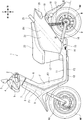
- FIG. 1 is a left side view of the electric motorcycle 1 according to the embodiment of the present invention.
- the electric motorcycle 1 is a scooter-type saddle-mounted vehicle having a low-floor floor 11 between the steering handle 2 and the seat 23.
- the body frame F of the electric motorcycle 1 includes a head pipe F1 that rotatably supports the steering stem 7, a main frame F2 extending rearward and downward from the head pipe F1, and an underframe extending rearward from the lower end of the main frame F2.
- the rear end portion of the rear frame F4 is exposed above the rear cowl 22 to form the grab rail 21.
- a steering handle 2 is attached to the upper end of the steering stem 7, and a bottom bridge 9 is fixed to the lower end of the steering stem 7.
- the bottom bridge 9 supports a pair of left and right front forks 10, and a front wheel WF is rotatably supported at the lower end of the front forks 10.
- a swing arm 16 is swingably supported by a pivot 14 provided on the rear frame F4.
- a side stand 15 is oscillatingly supported on the rear frame F4 on the lower front side of the pivot 14.
- the rear end portion of the swing arm 16 is suspended from the rear frame F4 by the rear cushion 17.
- the rear wheel WR which is rotatably supported by the rear end of the swing arm 16, has an in-wheel motor structure in which a motor M is arranged inside a wheel rim.
- a drum brake D for braking the rear wheel WR is arranged in the center of the motor M.
- the center of the steering handle 2 in the vehicle width direction is covered with a handle cover 4 that supports the headlight 5.
- a pair of left and right rearview mirrors 3 are attached to the steering wheel cover 4.
- a front cover 8 is arranged in front of the head pipe F1, and a leg shield 6 facing the driver's foot is attached to the rear side of the front cover 8.
- On the left and right sides of the low floor 11, under cowls 13 that cover the under frame F3 from the left and right are arranged.
- a lower cowl 12 is arranged below the front end of the seat 23, and a pair of left and right rear cowls 22 are arranged behind the lower cowl 12.
- a taillight device 20 is attached to the rear end of the rear cowl 22, and a rear fender 18 that supports a pair of left and right flasher lamps 19 is arranged below the taillight device 20.
- FIG. 2 is a block diagram showing the configuration of the control system of the in-wheel motor M.
- the body of the electric motorcycle 1 includes an HV battery 105 as a high-voltage battery for supplying electric power to the in-wheel motor M via an inverter 71, and a low-voltage battery for supplying electric power to the controller 101 and various electrical components. 12V battery 104 and the like are arranged.
- the PCU (power control unit) 100 that controls the electric power supplied to the motor M includes a controller 101 and an inverter 71.
- the controller drives the inverter 71 in response to signals from CAN communication, signals from the main switch, commands from various interfaces such as the throttle opening sensor, and outputs of the hall sensor and temperature sensor provided in the in-wheel motor M. do.
- the PCU 100 is arranged in the space inside the rear wheel WR like the in-wheel motor M and the drum brake D.
- FIG. 3 is a cross-sectional view taken along the line III-III of FIG.
- FIG. 4 is an exploded perspective view showing the configurations of the inner stator 50 and the control substrate 70 constituting the in-wheel motor M.
- the control board 70 has the function of the PCU 100 including the controller 101 and the inverter 71 described above.
- the control board 70 is configured by combining a printed circuit board 30 on which various electrical components are mounted and a metal plate 40 made of a metal such as aluminum, and has high rigidity.
- the axle 60 is fixed to the swing arm 16 so that it cannot rotate.
- the in-wheel motor M is arranged between the axle 60 and the wheel rim 81.
- a motor case 87 is rotatably supported on the outer peripheral side of the axle 60 via bearings 90 and 91.
- a wheel rim 81 is fixed to the outermost diameter portion of the motor case 87, and an outer rotor 80 is fixed at a position corresponding to the inner peripheral side of the wheel rim 81.
- the inner stator 50 arranged on the inner peripheral side of the outer rotor 80 is supported by a pedestal 51 fixed to the axle 60 and a controller board 70 fixed to the pedestal 51.
- the inner peripheral surface of the inner stator 50 is supported by a pedestal 51 extending radially outward from the axle 60.
- the control board 70 is fixed to the right side surface of the pedestal 51 in the vehicle width direction with bolts, adhesives, or the like.
- the pedestal 51 and the control board 70 are fixed in a range radially inside the bent portion 52 provided on the pedestal 51, and the position of the control board 70 on the outside side in the radial direction is the vehicle width of the inner stator 50. It is fixed to the right side surface in the direction by the fastening member 53. That is, the inner stator 50 has two points because the inner peripheral surface portion is supported by the pedestal 51 as the first mounting portion and the right side surface in the vehicle width direction is fixed to the control board 70 as the second mounting portion. It will be supported on the axle 60 side.
- FIG. 3 shows an example in which the right side surface of the inner stator 50 and the control substrate 70 are fixed only by the fastening member 53, the fastening member 53 and the adhesive are used together or fixed in close contact with each other without any gap. By doing so, it becomes possible to fix it more firmly.
- Both the first mounting portion and the second mounting portion are arranged on the right side with respect to the vehicle body center line C.
- An inverter 71 is arranged at a position closer to the inner side in the radial direction of the controller board 70, and a chip capacitor 72 is arranged at a position closer to the outer side in the radial direction of the controller board 70.
- a drum brake D is arranged on the left side of the motor case 87 in the vehicle width direction.
- the drum brake D is arranged at a position as close to the vehicle body center line C as possible.
- a recess 85 is formed which is recessed to a position where it overlaps with the inner stator 50 in the vehicle width direction, and a brake drum braked by the brake shoe 84 is formed on the side wall of the recess 85. 83 is formed.
- a heat insulating portion 82 having a groove shape is formed on the surface side of the motor case 87. According to the heat insulating portion 82, the heat generated when the drum brake D operates is less likely to be transmitted to the inner stator 50, and the influence on the motor temperature can be reduced.
- the heat insulating portion 82 may be an annular groove formed on the surface of the motor case 87, an intermittent broken line-shaped annular groove, or a closed passage for passing a refrigerant such as water. It may be configured.
- FIG. 5 is a cross-sectional view showing the configuration of the in-wheel motor M according to the modified example of the present embodiment.
- the same reference numerals as above indicate the same or equivalent parts.
- the present modification is characterized in that the cooling fins 99 are formed on the pedestal 51 that supports the inner peripheral portion of the inner stator 50.
- the pedestal 51 is made of a metal such as aluminum, and the cooling fin 99 is provided between the bent portion 52 and the axle 60 on the flat surface portion on the left side of the pedestal 51 in the vehicle width direction.
- the cooling fins 99 may be formed in an annular shape along the circumferential direction, or may be formed radially outward from the center in the radial direction. According to the cooling fins 99, in particular, the inverter 71 of the control board 70 can be efficiently cooled.
- the form of the electric motorcycle, the form of the in-wheel motor, the shape and structure of the inner stator and the outer rotor, the shape and structure of the brake drum and the brake shoe, etc. are not limited to the above embodiments and can be changed in various ways.
- the in-wheel motor structure according to the present invention can be applied to a saddle-mounted tricycle, a four-wheeled vehicle, or the like.
- 1 Electric two-wheeled vehicle, 50 ... Inner stator, 51 ... Pedestal (first mounting part), 52 ... Bending part, 60 ... Axle, 70 ... Control board (second mounting part), 71 ... Inverter, 80 ... Outer rotor, 81 ... Wheel rim, 82 ... Insulation, 83 ... Brake drum, 84 ... Brake shoe, 85 ... Recess, 87 ... Motor case, C ... Center in width direction, 99 ... Cooling fin, M ... In-wheel motor
Landscapes
- Engineering & Computer Science (AREA)
- General Engineering & Computer Science (AREA)
- Power Engineering (AREA)
- Mechanical Engineering (AREA)
- Chemical & Material Sciences (AREA)
- Combustion & Propulsion (AREA)
- Transportation (AREA)
- Microelectronics & Electronic Packaging (AREA)
- Arrangement Or Mounting Of Propulsion Units For Vehicles (AREA)
- Braking Arrangements (AREA)
- Connection Of Motors, Electrical Generators, Mechanical Devices, And The Like (AREA)
Priority Applications (2)
| Application Number | Priority Date | Filing Date | Title |
|---|---|---|---|
| CN202090001126.XU CN218514229U (zh) | 2020-03-05 | 2020-12-11 | 轮毂电机构造 |
| JP2022504978A JP7383117B2 (ja) | 2020-03-05 | 2020-12-11 | インホイールモータ構造 |
Applications Claiming Priority (2)
| Application Number | Priority Date | Filing Date | Title |
|---|---|---|---|
| JP2020037609 | 2020-03-05 | ||
| JP2020-037609 | 2020-03-05 |
Publications (1)
| Publication Number | Publication Date |
|---|---|
| WO2021176791A1 true WO2021176791A1 (ja) | 2021-09-10 |
Family
ID=77613267
Family Applications (1)
| Application Number | Title | Priority Date | Filing Date |
|---|---|---|---|
| PCT/JP2020/046255 Ceased WO2021176791A1 (ja) | 2020-03-05 | 2020-12-11 | インホイールモータ構造 |
Country Status (4)
| Country | Link |
|---|---|
| JP (1) | JP7383117B2 (https=) |
| CN (1) | CN218514229U (https=) |
| TW (1) | TWI771853B (https=) |
| WO (1) | WO2021176791A1 (https=) |
Cited By (2)
| Publication number | Priority date | Publication date | Assignee | Title |
|---|---|---|---|---|
| WO2024157749A1 (ja) * | 2023-01-25 | 2024-08-02 | 株式会社オートネットワーク技術研究所 | モータ |
| DE102023211129A1 (de) * | 2023-11-08 | 2025-05-08 | Continental Automotive Technologies GmbH | Radmotor mit radintegrierter Steuerung und Radbremse |
Citations (7)
| Publication number | Priority date | Publication date | Assignee | Title |
|---|---|---|---|---|
| JPH01157572U (https=) * | 1988-04-13 | 1989-10-31 | ||
| JP2003300420A (ja) * | 2002-04-10 | 2003-10-21 | Hiroshi Shimizu | 電気自動車のインホイールモータ |
| JP2004274838A (ja) * | 2003-03-06 | 2004-09-30 | Matsushita Electric Ind Co Ltd | 車輪駆動装置 |
| JP2006062388A (ja) * | 2004-08-24 | 2006-03-09 | Honda Motor Co Ltd | 車両用ホイール駆動装置 |
| KR20070100524A (ko) * | 2006-04-07 | 2007-10-11 | 엘지전자 주식회사 | 모터 및 그를 갖는 공기조화기 |
| WO2019130904A1 (ja) * | 2017-12-29 | 2019-07-04 | ヤマハ発動機株式会社 | 鞍乗型電動車両 |
| JP2020014303A (ja) * | 2018-07-17 | 2020-01-23 | 株式会社e−Gle | アウターロータ型モータ、および、電気自動車 |
Family Cites Families (7)
| Publication number | Priority date | Publication date | Assignee | Title |
|---|---|---|---|---|
| JP3625021B2 (ja) * | 1998-03-13 | 2005-03-02 | 光洋精工株式会社 | ブレーキ内蔵型自転車発電機 |
| JP3913482B2 (ja) * | 2001-01-26 | 2007-05-09 | 三洋電機株式会社 | 補助動力付き車両 |
| KR101444571B1 (ko) * | 2010-03-23 | 2014-09-24 | 혼다 기켄 고교 가부시키가이샤 | 하이브리드식 안장형 차량 |
| JP5149938B2 (ja) * | 2010-06-11 | 2013-02-20 | 株式会社シマノ | モータ内蔵自転車用ハブ |
| KR20140004801U (ko) * | 2013-02-19 | 2014-08-27 | 젱 화 엔터프라이지스 컴퍼니 리미티드 | 하이브리드 모터사이클 |
| DE202013102672U1 (de) * | 2013-06-20 | 2014-09-23 | Hightec Edv-Systeme Gmbh | Kabelanschluss für eine Motorbaueinheit eines elektrischen Fahrradhilfsantriebs |
| EP3733495A4 (en) * | 2017-12-29 | 2021-01-27 | Yamaha Hatsudoki Kabushiki Kaisha | ELECTRIC SADDLE VEHICLE |
-
2020
- 2020-12-11 JP JP2022504978A patent/JP7383117B2/ja active Active
- 2020-12-11 WO PCT/JP2020/046255 patent/WO2021176791A1/ja not_active Ceased
- 2020-12-11 CN CN202090001126.XU patent/CN218514229U/zh active Active
- 2020-12-30 TW TW109146768A patent/TWI771853B/zh not_active IP Right Cessation
Patent Citations (7)
| Publication number | Priority date | Publication date | Assignee | Title |
|---|---|---|---|---|
| JPH01157572U (https=) * | 1988-04-13 | 1989-10-31 | ||
| JP2003300420A (ja) * | 2002-04-10 | 2003-10-21 | Hiroshi Shimizu | 電気自動車のインホイールモータ |
| JP2004274838A (ja) * | 2003-03-06 | 2004-09-30 | Matsushita Electric Ind Co Ltd | 車輪駆動装置 |
| JP2006062388A (ja) * | 2004-08-24 | 2006-03-09 | Honda Motor Co Ltd | 車両用ホイール駆動装置 |
| KR20070100524A (ko) * | 2006-04-07 | 2007-10-11 | 엘지전자 주식회사 | 모터 및 그를 갖는 공기조화기 |
| WO2019130904A1 (ja) * | 2017-12-29 | 2019-07-04 | ヤマハ発動機株式会社 | 鞍乗型電動車両 |
| JP2020014303A (ja) * | 2018-07-17 | 2020-01-23 | 株式会社e−Gle | アウターロータ型モータ、および、電気自動車 |
Cited By (2)
| Publication number | Priority date | Publication date | Assignee | Title |
|---|---|---|---|---|
| WO2024157749A1 (ja) * | 2023-01-25 | 2024-08-02 | 株式会社オートネットワーク技術研究所 | モータ |
| DE102023211129A1 (de) * | 2023-11-08 | 2025-05-08 | Continental Automotive Technologies GmbH | Radmotor mit radintegrierter Steuerung und Radbremse |
Also Published As
| Publication number | Publication date |
|---|---|
| TWI771853B (zh) | 2022-07-21 |
| CN218514229U (zh) | 2023-02-21 |
| TW202140325A (zh) | 2021-11-01 |
| JP7383117B2 (ja) | 2023-11-17 |
| JPWO2021176791A1 (https=) | 2021-09-10 |
Similar Documents
| Publication | Publication Date | Title |
|---|---|---|
| JP5225956B2 (ja) | 電動式鞍乗型車両 | |
| CN102448806B (zh) | 电动式鞍乘型车辆 | |
| JP5715932B2 (ja) | ディスクブレーキ装置 | |
| TWI488771B (zh) | 電動車輛 | |
| JP6630335B2 (ja) | 鞍乗り型車両 | |
| US10507884B2 (en) | Rear brake device of vehicle | |
| JP7383117B2 (ja) | インホイールモータ構造 | |
| KR20140038024A (ko) | 전기 자전거 | |
| WO2015079478A1 (ja) | 自動二輪車 | |
| US10605320B2 (en) | Disc brake rotor assembly and brake system | |
| JP6670814B2 (ja) | 鞍乗り型車両 | |
| CN102530138A (zh) | 机动二轮车的灯光装置 | |
| JP2011035954A (ja) | モータ駆動装置及びこれを搭載した電動車両 | |
| JP4316257B2 (ja) | 車両用放電ランプ装置 | |
| US11951899B1 (en) | Accessory lights for a two-wheeled vehicle | |
| CN112770969B (zh) | 电动车辆 | |
| JP5129713B2 (ja) | 電気自動二輪車 | |
| JP2000168667A (ja) | 自動二輪車 | |
| JP2009090887A (ja) | 鞍乗型車両 | |
| CN216546554U (zh) | 一种中置电机悬挂安装结构及动力系统 | |
| WO2020066239A1 (ja) | 鞍乗り型電動車両 | |
| CN112770965B (zh) | 电动车辆 | |
| JP3324192B2 (ja) | 電動式スクータ型車両 | |
| JP3157690U (ja) | 鞍乗型車両 | |
| CN219601514U (zh) | 摩托车 |
Legal Events
| Date | Code | Title | Description |
|---|---|---|---|
| 121 | Ep: the epo has been informed by wipo that ep was designated in this application |
Ref document number: 20923187 Country of ref document: EP Kind code of ref document: A1 |
|
| DPE1 | Request for preliminary examination filed after expiration of 19th month from priority date (pct application filed from 20040101) | ||
| ENP | Entry into the national phase |
Ref document number: 2022504978 Country of ref document: JP Kind code of ref document: A |
|
| NENP | Non-entry into the national phase |
Ref country code: DE |
|
| 122 | Ep: pct application non-entry in european phase |
Ref document number: 20923187 Country of ref document: EP Kind code of ref document: A1 |
|
| WWG | Wipo information: grant in national office |
Ref document number: 202247049483 Country of ref document: IN |