WO2021176510A1 - 歯車ポンプ又は歯車モータおよび歯車ポンプ又は歯車モータの製造方法 - Google Patents
歯車ポンプ又は歯車モータおよび歯車ポンプ又は歯車モータの製造方法 Download PDFInfo
- Publication number
- WO2021176510A1 WO2021176510A1 PCT/JP2020/008663 JP2020008663W WO2021176510A1 WO 2021176510 A1 WO2021176510 A1 WO 2021176510A1 JP 2020008663 W JP2020008663 W JP 2020008663W WO 2021176510 A1 WO2021176510 A1 WO 2021176510A1
- Authority
- WO
- WIPO (PCT)
- Prior art keywords
- gear
- recess
- face
- storage chamber
- contact
- Prior art date
- Legal status (The legal status is an assumption and is not a legal conclusion. Google has not performed a legal analysis and makes no representation as to the accuracy of the status listed.)
- Ceased
Links
Images






Classifications
-
- F—MECHANICAL ENGINEERING; LIGHTING; HEATING; WEAPONS; BLASTING
- F04—POSITIVE - DISPLACEMENT MACHINES FOR LIQUIDS; PUMPS FOR LIQUIDS OR ELASTIC FLUIDS
- F04C—ROTARY-PISTON, OR OSCILLATING-PISTON, POSITIVE-DISPLACEMENT MACHINES FOR LIQUIDS; ROTARY-PISTON, OR OSCILLATING-PISTON, POSITIVE-DISPLACEMENT PUMPS
- F04C2/00—Rotary-piston machines or pumps
- F04C2/08—Rotary-piston machines or pumps of intermeshing-engagement type, i.e. with engagement of co-operating members similar to that of toothed gearing
- F04C2/10—Rotary-piston machines or pumps of intermeshing-engagement type, i.e. with engagement of co-operating members similar to that of toothed gearing of internal-axis type with the outer member having more teeth or tooth-equivalents, e.g. rollers, than the inner member
-
- F—MECHANICAL ENGINEERING; LIGHTING; HEATING; WEAPONS; BLASTING
- F04—POSITIVE - DISPLACEMENT MACHINES FOR LIQUIDS; PUMPS FOR LIQUIDS OR ELASTIC FLUIDS
- F04C—ROTARY-PISTON, OR OSCILLATING-PISTON, POSITIVE-DISPLACEMENT MACHINES FOR LIQUIDS; ROTARY-PISTON, OR OSCILLATING-PISTON, POSITIVE-DISPLACEMENT PUMPS
- F04C2/00—Rotary-piston machines or pumps
- F04C2/08—Rotary-piston machines or pumps of intermeshing-engagement type, i.e. with engagement of co-operating members similar to that of toothed gearing
- F04C2/12—Rotary-piston machines or pumps of intermeshing-engagement type, i.e. with engagement of co-operating members similar to that of toothed gearing of other than internal-axis type
- F04C2/14—Rotary-piston machines or pumps of intermeshing-engagement type, i.e. with engagement of co-operating members similar to that of toothed gearing of other than internal-axis type with toothed rotary pistons
- F04C2/18—Rotary-piston machines or pumps of intermeshing-engagement type, i.e. with engagement of co-operating members similar to that of toothed gearing of other than internal-axis type with toothed rotary pistons with similar tooth forms
Definitions
- the present invention relates to a gear pump or a gear motor and a method for manufacturing a gear pump or a gear motor.
- the gear pump of Patent Document 1 includes a drive gear, a driven gear, and a casing.
- the casing includes a main body having a first end face and a second end face, a mounting attached to the first end face of the main body, and a cover attached to the second end face of the main body.
- the main body has an internal space, and the drive gear and the driven gear are housed in the internal space.
- the interior space is closed by mounting and casing.
- the positions of the parts that make up the casing shift, the positions of the drive gear and driven gear housed inside the casing also shift.
- the drive gear and the driven gear cannot rotate stably.
- the drive gear and driven gear may be damaged. Further, the transfer efficiency of the liquid flowed by the driving gear and the driven gear may decrease.
- An object of the present invention is to provide a gear pump or gear motor in which parts constituting a casing are positioned with high accuracy, and a method for manufacturing the gear pump or gear motor.
- the gear pump or gear motor and the method for manufacturing the gear pump or gear motor according to the present invention have the following configurations.
- the gear pump or gear motor of the present invention includes a pair of gears that mesh with each other, a body having a first end surface, an inner wall formed inside the body, and an inner wall in which the tooth tips of the gears are in contact with a part thereof. It is formed by an inner wall, has a gear storage chamber for storing gears, a first cover having a second end surface and having a second end surface attached to the first end surface of the body, and the first end surface.
- a first positioning member that is placed in a space formed by a first recess, a second recess formed on the second end surface, and the first recess and the second recess, and is in contact with the first recess and the second recess. To be equipped.
- the method for manufacturing a gear pump or a gear motor of the present invention includes a step of preparing a body provided with a first end surface and an inner wall and having a gear storage chamber formed by the inner wall, and a step of forming a first recess on the first end face.
- a first positioning member is placed in the space formed by the first recess and the second recess so as to be in contact with the first recess and the second recess, and the first end surface is in contact with a part of the inner wall so that the tip of the gear is in contact with the tooth tip. It is provided with a step of bringing the second end face into contact with the second end face.
- the gear pump or gear motor of the present invention is formed by a pair of gears that mesh with each other, a body having a first end surface, an inner wall formed inside the body, and the inner wall, and houses the gears.
- a first cover having a gear storage chamber, a partition piece provided in the gear storage chamber where the tooth tips of the gears are in contact with a part thereof, and a second end surface, and the second end surface is attached to the first end surface of the body.
- a first positioning member in contact with the second recess is provided.
- the method for manufacturing a gear pump or a gear motor of the present invention includes a step of preparing a body having a first end face and an inner wall, a gear storage chamber formed by the inner wall, and a partition piece in the gear storage chamber, and the above-mentioned step.
- the first positioning member is inserted so as to be in contact with the first recess and the second recess in the space formed by the first recess and the second recess so that the tip of the gear is in contact with a part of the partition piece. Is provided with a step of bringing the first end face and the second end face into contact with each other.
- the gear by making the gear smaller than the inner wall forming the gear storage chamber, the gear can easily enter the gear storage chamber. Since a part of the tooth tip of the gear comes into contact with the inner wall, there is no liquid leakage and the transfer efficiency is not reduced.
- the gear pump 10 of the present application shown in FIG. 1 is a circumscribed gear pump.
- the gear pump 10 includes gears 12 and 14, shafts 16 and 18 that rotatably support the gears 12 and 14, and a casing 20 in which the gears 12 and 14 and shafts 16 and 18 are housed.
- the gears 12 and 14 are composed of a drive gear 12 and a driven gear 14. Each of the gears 12 and 14 has a plurality of teeth arranged at equal intervals on a circular bottom circle (FIG. 2). The drive gear 12 and the driven gear 14 are in mesh with each other. As the drive gear 12 rotates, the driven gear 14 also rotates.
- the drive shaft 16 is formed integrally with the drive gear 12.
- the drive shaft 16 is arranged perpendicular to the side surface 22 from the center of the side surface 22 of the drive gear 12.
- a driven shaft 18 is formed integrally with the driven gear 14.
- the driven shaft 18 is arranged perpendicular to the side surface 24 from the center of the side surface 24 of the driven gear 14.
- the casing 20 includes a body 26 and a first cover 28.
- An inner wall 30 is formed inside the body 26, and the gear storage chamber 32 is formed by the inner wall 30.
- the gear storage chamber 32 is a space.
- the drive gear 12 and the driven gear 14 are housed in the gear storage chamber 32 in a meshed state.
- the body 26 includes a first end face 34, and the first cover 28 includes a second end face 36.
- the second end surface 36 is in contact with the first end surface 34, and the gear storage chamber 32 is closed by the first cover 28.
- Bearing holes 38 are formed in the body 26 and the first cover 28.
- the bearing hole 38 is connected to the gear storage chamber 32.
- the drive shaft 16 and the driven shaft 18 are passed through the bearing hole 38 via the bush 40.
- the suction passage 42 and the discharge passage 44 are formed in the body 26 (FIG. 2).
- the suction passage 42 is a passage for sucking a liquid (hydraulic oil) into the gear storage chamber 32.
- the discharge passage 44 is a passage for discharging the liquid from the gear storage chamber 32.
- the side plate 46 is housed in the gear storage chamber 32.
- the side surfaces 22 and 24 of the gears 12 and 14 rotate while being in contact with the side plate 46.
- the side plate 46 is a plate body having good slidability.
- the side plate 46 may be omitted, and the body 26 and the first cover 28 may be in contact with the side surfaces 22 and 24 of the gears 12 and 14.
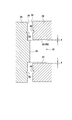
- the first recess 48 is formed on the first end surface 34, and the second recess 50 is formed on the second end surface 36 (FIGS. 2 and 3).
- the shapes of the first recess 48 and the second recess 50 include a conical shape or a pyramid shape (FIG. 4).
- the first recess 48 and the second recess 50 are each a plurality, for example, two.
- the shapes of the first recess 48 and the second recess 50 are the same.
- the first positioning member 52 is placed in a space formed by the first recess 48 and the second recess 50.
- the shape of the first positioning member 52 is spherical.
- the first positioning member 52 is in contact with the first recess 48 and the second recess 50.
- the first positioning member 52 is inserted into the first recess 48 and the second recess 50.
- the position of the first cover 28 with respect to the body 26 is determined. Since the first positioning member 52 includes a spherical shape, it is easy to position the first cover 28 when the first cover 28 is attached to the body 26.
- the in-row portion 54 is formed on the second end surface 36 of the first cover 28 (FIGS. 1 and 3). The in-row portion 54 projects from the second end surface 36 of the first cover 28. The in-row portion 54 is put into the gear storage chamber 32.
- the outer shape of the inlay portion 54 is smaller than the inner wall 30 forming the gear storage chamber 32.
- the in-row portion 54 can easily enter the gear storage chamber 32.
- the first cover 28 can be easily attached to the body 26.
- a gap is created between the inlay portion 54 and the inner wall 30.
- the in-row portion 54 is arranged in the center of the gear storage chamber 32, the liquid in the discharge passage 44 flows back into the suction passage 42.
- a part of the inlay portion 54 contacts a part of the inner wall 30. It is possible to prevent the liquid from flowing back from between the in-row portion 54 and the inner wall 30.
- the liquid in the suction passage 42 has a relatively low pressure.
- the portion of the inner wall 30 forming the gear storage chamber 32 connected to the suction passage 42 has a low pressure.
- the portion connected to the suction passage 42 is a portion 58 in which the tooth grooves 56 of the gears 12 and 14 are connected to the suction passage 42 (see FIG. 7).
- a part of the in-row portion 54 is brought into contact with at least the portion 58 of the inner wall 30 of the portion where the pressure is reduced.
- the inlay portion 54 does not come into contact with the inner wall 30 of the portion where the liquid pressure is high.
- FIGS. 5 and 6 are shown so that the difference between the gear storage chamber 32 and the inlay portion 54 can be seen, the difference is actually very small.
- the positions of the first recess 48 and the second recess 50 are determined so that a part of the inlay portion 54 is in contact with the portion 58 of the inner wall 30 of the body 26.
- the in-row portion 54 is arranged in the center of the gear storage chamber 32, it is assumed that only A has a gap between the in-row portion 54 and the inner wall 30 (FIG. 5).
- the difference between the position of the first recess 48 and the position of the second recess 50 is set to A.
- a plurality of first recesses 48 and second recesses 50 are arranged so as to sandwich the gear storage chamber 32 and the inlay portion 54.
- the first recess 48 is closer to the gear storage chamber 32 than the second recess 50
- the second recess 50 is closer to the first recess 48 than the first recess 48. It is close to the gear storage chamber 32.
- the inner wall 30 is a portion 58 in which the liquid flowing through the gear storage chamber 32 has a high pressure (FIG. 6). If a part of the in-row portion 54 is in contact with the portion 58, the other portion of the in-row portion 54 may or may not be in contact with the inner wall 30.
- the rotation trajectory of the tooth tips of the gears 12 and 14 is smaller than that of the inner wall 30.
- the gears 12 and 14 are easily stored in the gear storage chamber 32. Further, the tips of some of the rotating gears 12 and 14 come into contact with the inner wall 30.
- the portion of the inner wall 30 in contact with the tooth tips is the portion 58 where the pressure of the liquid is reduced. That is, the tooth tip comes into contact with the portion 58 of the inner wall 30 connected to the suction passage 42 as in the inlay portion 54. It is possible to prevent the liquid from leaking from the contacting portion 58. If the tooth tip comes into contact with the low pressure portion 58, the tooth tip may also come into contact with other parts of the inner wall 30.
- the gears 12 and 14 rotate while the tooth tips of the gears 12 and 14 are in contact with a part of the inner wall 30.
- a ring-shaped elastic member 60 is arranged on the second end surface 36 to prevent liquid from leaking from the gap between the first end surface 34 and the second end surface 36.
- a body 26 having a gear storage chamber 32, a bearing hole 38, and a first end surface 34 is prepared. Further, a first cover 28 having a bearing hole 38, a second end surface 36, and a first inlay portion 54 is prepared.
- the body 26 and the first cover 28 can be manufactured by various methods such as casting, forging, or cutting.
- the first recess 48 is formed on the first end surface 34, and the second recess 50 is formed on the second end surface 36.
- the first recess 48 and the second recess 50 can be formed by cutting or the like.
- the distance between the first recesses 48 is the same as the distance between the second recesses 50.
- the second recess 50 is displaced toward the high pressure side (discharge passage 44 side) with respect to the first recess 48 (FIG. 5).
- the second recess 50 is shifted to the high pressure side with respect to the first recess 48.
- the first inlay portion 54 is placed on the low pressure side (suction passage 42). Move to the side).
- the state of FIG. 5 changes to the state of FIG. As a result, the first inlay portion 54 comes into contact with the inner wall 30 on the low pressure side.
- the shafts 16 and 18 of the gears 12 and 14 have a gap with respect to the bearing hole 38 or the bush 40, and the gears 12 and 14 have a gap with respect to the inner wall 30.
- the gears 12 and 14 and the shafts 16 and 18 move to the low pressure side. At least the tooth tips of the gears 12 and 14 should be in contact with the low pressure portion of the inner wall 30.
- the gears 12, 14 and the in-row portion 54 are made smaller than the gear storage chamber 32 and have a gap, so that the gears 12, 14 and the in-row portion 54 can be easily inserted into the gear storage chamber 32.
- Leakage of liquid can be prevented by having a part of the in-row portion 54 in contact with a part of the inner wall 30 forming the gear storage chamber 32.
- Liquid leakage can be prevented by contacting the tooth tips of the gears 12 and 14 with a part of the inner wall 30.
- the gear motor 10 has good liquid transfer efficiency.
- the cover 82 of the gear pump 80 of FIG. 8 includes a body 84, a first cover 28, and a second cover 86.
- the body 84 includes a third end face 88.
- the third end surface 88 is provided on the opposite side of the first end surface 34 in the length direction of the shaft.
- the second cover 86 is attached to the third end surface 88.
- the second cover 86 includes a fourth end surface 90, and the third end surface 88 and the fourth end surface 90 are in contact with each other.
- the second cover 86 includes a bearing hole 38 into which the shafts 16 and 18 are inserted. The shafts 16 and 18 are passed through the bearing holes 38 via the bush 40.
- the third recess 92 is formed on the third end surface 88, and the fourth recess 94 is formed on the fourth end surface 90.
- the second positioning member 96 is placed in the space formed by the third recess 92 and the fourth recess 94.
- the second positioning member 96 has a spherical shape.
- the second positioning member 96 is in contact with the third recess 92 and the fourth recess 94. Similar to the first embodiment, when the second cover 86 is attached to the body 84, the positioning member 96 is inserted into the third recess 92 and the fourth recess 94.
- a second inlay portion 98 is provided on the fourth end surface 90.
- the second in-row portion 98 projects from the fourth end surface 90.
- the second in-row portion 98 is put into the gear storage chamber 32. Similar to the first in-row portion 54 of the first embodiment, a part of the second in-row portion 98 comes into contact with a part of the inner wall 30 forming the gear storage chamber 32. Similar to the first embodiment, a part of the inner wall 30 thereof is a portion 58 in which the liquid has a low pressure. Further, as in the first embodiment, the tooth tip comes into contact with the low pressure portion 58 of the inner wall 30.
- the method of manufacturing the gear pump 80 is the same as that of the first embodiment in that the body 84 and the first cover 28 are attached. The differences are the step of preparing the body 84 having the third end face 88, the step of preparing the second cover 86 having the fourth end face 90, and the step of attaching the second cover 86 to the body 84.
- a second inlay portion 98 is formed on the fourth end surface 90.
- a third recess 92 is formed on the third end surface 88, and a fourth recess 94 is formed on the fourth end surface 90.
- the third recess 92 and the fourth recess 94 are formed by cutting or the like.
- the bush 40 is attached to the bearing hole 38 of the second cover 86, and the side plate 46 is passed through the shafts 16 and 18 of the gears 12 and 14. In that state, the shafts 16 and 18 are passed through the bearing holes 38 of the second cover 86.
- the second positioning member 96 is inserted into the space formed by the third recess 92 and the fourth recess 94.
- the fourth recess 94 is displaced to the high pressure side with respect to the third recess 92, and when the third recess 92 and the fourth recess 94 face each other, the second inlay portion 98 is on the low pressure side. Moving. The second inlay portion 98 is in contact with the low pressure portion of the inner wall 30.
- the first in-row portion 54 provided in the first cover 28 may not be provided.
- the second in-row portion 98 provided in the second cover 86 may be omitted.
- the first in-row portion 54, the second in-row portion 98, or both may be omitted. Even if the inlay portions 54 and 98 are not provided, the tooth tips of the gears 12 and 14 are in contact with a part of the inner wall 30 forming the gear storage chamber 32, and the recesses 48, 50, 92, 94 and the positioning members are provided. Adjust the positions of 52 and 96.
- the gear pump 100 in FIG. 10 is an internal gear pump.
- the gear pump 100 includes a drive gear 102, a driven gear 104, a drive shaft 106 that rotatably supports the drive gear 102, and a casing 108 that houses the gears 102, 104 and the drive shaft 106.
- the driven gear 104 has a ring shape and has teeth on the inner circumference thereof.
- the drive gear 102 is arranged inside the driven gear 104.
- the teeth of the drive gear 102 mesh with the teeth of the driven gear 104.
- the driven gear 104 also rotates.
- a drive shaft 106 is formed integrally with the drive gear 102.
- the drive shaft 106 is arranged perpendicular to the side surface 110 from the center of the side surface 110 of the drive gear 102.
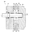
- Casing 108 includes a body 112 and a first cover 114 (FIGS. 11 and 12).
- An inner wall 116 is formed inside the body 112.
- the space formed by the inner wall 116 is the gear storage chamber 118.
- the drive gear 102 and the driven gear 104 are housed in the gear storage chamber 118.
- the body 112 includes a first end face 120
- the first cover 114 includes a second end face 122.
- the second end surface 122 is in contact with the first end surface 120, and the gear storage chamber 118 is closed by the first cover 114.
- Bearing holes 124 are formed in the body 112 and the first cover 114, and the bearing holes 124 are connected to the gear storage chamber 118.
- the drive shaft 106 is passed through the bearing hole 124 via the bush 126.
- the side plates in contact with the side surfaces of the gears 102 and 104 may be provided, or the side plates may be omitted.
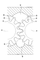
- a partition piece 128 is provided in the gear storage chamber 118. In a space where the drive gear 102 and the driven gear 104 are not engaged, the partition piece 128 is arranged between the drive gear 102 and the driven gear 104.
- the partition piece 128 includes a first arc portion 130 and a second arc portion 132 formed on the opposite side of the first arc portion 130. A part of the first arc portion 130 is in contact with the tooth tip of the drive gear 102, and a part of the second arc portion 132 is in contact with the tooth tip of the driven gear 104.
- the suction passage 134 and the discharge passage 136 are formed in the casing 108.
- the suction passage 134 is a passage for sucking the liquid into the gear storage chamber 118
- the discharge passage 136 is a passage for discharging the liquid from the gear storage chamber 118.
- Two spaces are formed by the drive gear 102, the driven gear 104, and the partition piece 128.
- One of them is the first space 138 and the other is the second space 140 (FIG. 11).
- the first space 138 is connected to the suction passage 134
- the second space 140 is connected to the discharge passage 136.
- the liquid contained in the gear storage chamber 118 from the suction passage 134 enters the first space 138.
- the drive shaft 106 is rotated, the drive gear 102 and the driven gear 104 are rotated, and the liquid is moved from the first space 138 to the second space 140.
- the liquid in the second space 140 is flowed through the discharge passage 136. Comparing the liquid in the suction passage 134 and the liquid in the discharge passage 136, the liquid in the discharge passage 136 has a relatively high pressure.
- the rotation locus of the tooth tip of the drive gear 102 is smaller than that of the first arc portion 130 of the partition piece 128.
- the rotation locus of the tooth tip of the driven gear 104 is larger than that of the second arc portion 132 of the partition piece 128.
- the drive gear 102 and the driven gear 104 can be easily inserted into the gear storage chamber 118.
- the liquid transfer efficiency deteriorates.
- a part of the first arc portion 130 of the partition piece 128 and the tooth tip of the drive gear 102 are in contact with each other, and a part of the second arc portion 132 of the partition piece 128 is in contact with the tooth tip of the driven gear 104.
- the gears 102 and 104 come into contact with a part of the partition piece 128, the liquid is prevented from flowing back from the second space 140 to the first space 138.
- the portion of the partition piece 128 in contact with the gears 102 and 104 is at least the portion in contact with the first space 138. Since the pressure of the liquid in the second space 140 is higher than the pressure of the liquid in the first space 138, the liquid in the second space 140 tends to expand. By this expansion, a force is applied to the drive gear 102 and the driven gear 104. In the first space 138, a force is applied to the drive gear 102 in a direction of being pressed against the partition piece 128, and a force is applied to the driven gear 104 in a direction of being attracted to the partition piece 128.
- the first end surface 120 is formed with the first recess 142
- the second end surface 122 is formed with the second recess 144.
- the first positioning member 146 is placed in the space formed by the first recess 142 and the second recess 144.
- the first positioning member 146 is in contact with the first recess 142 and the second recess 144.
- a body 112 having a gear storage chamber 118, a bearing hole 124, and a first end surface 120 is prepared. Further, a first cover 114 having a bearing hole 124 and a second end surface 122 is prepared.
- the body 112 and the first cover 114 can be manufactured by various methods such as casting, forging, or cutting.
- the first recess 142 is formed on the first end surface 120, and the second recess 144 is formed on the second end surface 122.
- the first recess 142 and the second recess 144 can be formed by cutting or the like.
- the number of the first recesses 142 is plural, and the number of the second recesses 144 is the same as that of the first recesses 142.
- the distance between the first recesses 142 is the same as the distance between the second recesses 144.
- the second recess 144 is displaced toward the high pressure side (discharge passage 44 side) with respect to the first recess 142 (FIG. 5).
- the drive shaft 106 is inserted into the bearing hole 124 of the first cover 114, and the second end surface 122 is brought into contact with the first end surface 120. At that time, the first positioning member 146 is inserted into the space formed by the first recess 142 and the second recess 144.
- the second recess 144 is displaced to the high pressure side with respect to the first recess 142. Therefore, when the space first positioning member 146 formed by the first recess 142 and the second recess 144 is inserted so that the first recess 142 and the second recess 144 face each other, the gear 102 is the same as in the first embodiment. , 104 and the drive shaft 106 move to the low pressure side. At least the tooth tips of the gears 102 and 104 should be in contact with the low pressure portion of the partition piece 128.
- the gears 102 and 104 can be easily put into the gear storage chamber 118, and the liquid transfer efficiency can be increased.
- the gear pump 150 of FIG. 13 includes a body 152, a first cover 114, and a second cover 154.
- the body 152 includes a third end face 156.
- the third end surface 156 is provided on the opposite side of the first end surface 112 in the length direction of the shaft.
- the second cover 154 contacts the third end surface 156.
- the second cover 154 includes a fourth end surface 158, the fourth end surface 158 of which is in contact with the third end surface 156.
- the third recess 160 is formed on the third end surface 156, and the fourth recess 162 is formed on the fourth end surface 158.
- the second positioning member 164 is placed in the space formed by the third recess 160 and the fourth recess 162.
- the second positioning member 164 has a spherical shape.
- the second positioning member 164 is in contact with the third recess 160 and the fourth recess 162. Similar to the second embodiment, when the second cover 154 is attached to the body 152, the second positioning member 164 is inserted into the third recess 160 and the fourth recess 162.
- the method of manufacturing the gear pump 150 is the same as that of the fourth embodiment in that the body 112 and the first cover 114 are attached. The differences are the step of preparing the body 152 having the third end face 156, the step of preparing the second cover 154 having the fourth end face 158, and the step of attaching the second cover 154 to the body 152.
- a third recess 160 is formed on the third end surface 156, and a fourth recess 162 is formed on the fourth end surface 158.
- the third recess 160 and the fourth recess 158 are formed by cutting or the like.
- the bush 126 is attached to the bearing hole 124 of the second cover 154, and the drive shaft 106 is passed through the bearing hole 124 of the second cover 154.
- the second positioning member 164 is inserted into the space formed by the third recess 160 and the fourth recess 158.
- the fourth recess 162 is displaced to the high pressure side with respect to the third recess 160, and when the third recess 160 and the fourth recess 162 are opposed to each other, the tooth tips of the gears 102 and 104 are partitioned. It touches the low pressure part of the piece 128.
- the first cover 114 may be provided with a first in-row portion
- the second cover 154 may be provided with a second in-row portion, or both.
- the outer shape of the in-row portion is smaller than the inner wall 116 forming the gear storage chamber 118.
- the in-row portion is easy to store in the gear storage chamber 118.
- a part of the inner wall 116 forming the gear storage chamber 118 is in contact with the in-row portion. It prevents the liquid from leaking from between the inner wall 116 and the inlay portion and lowering the liquid transfer efficiency.
- the in-row portion is in contact with a portion of the inner wall 116 of the gear storage chamber 118 where the liquid is at low pressure. Similar to the first embodiment, since the in-row portion is moved to the low-pressure portion from the beginning, the misalignment of the in-row portion can be prevented.
- the positions of the recesses 142, 144, 160, and 162 are determined so that the in-row portion is in contact with the low-pressure portion in the inner wall 116 as described in the first and second embodiments. Keep it.
- the first positioning member 146 is inserted into the space formed by the first recess 142 and the second recess 144, the inlay portion moves to the low pressure side, and the inrow portion comes into contact with the low pressure portion of the inner wall.
- the second positioning member 164 is inserted into the space formed by the third recess 160 and the fourth recess 162
- the inlay portion moves to the low pressure side, and the inrow portion comes into contact with the low pressure portion of the inner wall 116.
- the shapes of the recesses 48, 50, 92, 94, 142, 144, 160, 162 and the positioning members 52, 96, 146, 164 are not limited.
- the positioning member 170 may have a conical portion and a spherical portion that match the conical shape of the recess 48.
- it may have a pyramid portion or a rod-shaped positioning member.
- the shape of the recess may be appropriately changed according to the shape of the positioning member.
- the gear pump or gear motor is formed inside the body, a gear having a pair of gears and a body having a first end face, and a part of the tooth tips of the gears.
- a first cover having an inner wall in contact with the inner wall, a gear storage chamber formed by the inner wall and accommodating gears, a second end face, and a second end face attached to the first end face of the body, and the first cover. It is placed in a space formed by a first recess formed on one end surface, a second recess formed on the second end face, and the first recess and the second recess, and is formed into the first recess and the second recess. It includes a first positioning member in contact with the first positioning member.
- the rotation trajectory of the tooth tip of the gear is smaller than that of the inner wall, making it easier for the gear to enter the gear storage chamber.
- a suction passage formed in the body for supplying a liquid to the gear storage chamber and a discharge passage formed in the body for discharging a liquid from the gear storage chamber are provided.
- the pressure of the liquid on the discharge passage side is higher than that on the suction passage side, and the inner wall and the gear forming the gear storage chamber are formed in the portion of the gear storage chamber where the liquid becomes low pressure. The tip of the tooth touches.
- a force is applied to the gear from the high pressure side to the low pressure side of the liquid, and the tooth tip of the gear is in contact with the portion where the pressure is low from the beginning, so that the position of the gear There is no deviation.
- the liquid leakage is eliminated because the first inlay portion is in contact with a part of the inner wall.
- a second cover having a third end face formed on the body, a fourth end face, and a fourth end face attached to the third end face of the body, and a second cover formed on the third end face.
- a third recess which is placed in a space formed by the third recess, the fourth recess formed on the fourth end surface, and the third recess and the fourth recess, is in contact with the third recess and the fourth recess, and has a spherical portion. 2 With a positioning member.
- the method for manufacturing a gear pump or a gear motor includes a step of preparing a body provided with a first end surface and an inner wall and having a gear storage chamber formed by the inner wall, and a first end surface.
- the first positioning member is inserted into the space formed by the first recess and the second recess so as to be in contact with the first recess and the second recess, and the tip of the gear is placed on a part of the inner wall.
- a step of bringing the first end face and the second end face into contact with each other is provided.
- the first end face and the second end face are brought into contact with each other so that the tooth tips of the gear come into contact with a part of the inner wall, and from between the gear and the inner wall. It is possible to prevent the liquid from flowing back.
- a suction passage formed in the body for supplying a liquid to the gear storage chamber and a discharge passage formed in the body for discharging a liquid from the gear storage chamber are provided.
- the pressure of the liquid on the discharge passage side is higher than that on the suction passage side, and in the step of bringing the first end face into contact with the second end face, the liquid in the gear storage chamber becomes low pressure.
- the first end surface and the second end surface are brought into contact with each other so that the inner wall forming the gear storage chamber and the tooth tip of the gear are in contact with each other.
- the gear is arranged so that the tooth tip of the gear comes into contact with the portion where the force is applied to the gear from the high pressure side to the low pressure side of the liquid and the pressure becomes low from the beginning. Therefore, the misalignment of the gears is eliminated.
- a step of forming the fourth recess and a second positioning member are inserted in the space formed by the third recess and the fourth recess so as to be in contact with the third recess and the fourth recess, and a gear is formed on a part of the inner wall.
- a step of bringing the third end face and the fourth end face into contact with each other so that the tooth tips are in contact with each other is provided.
- positioning can be performed by the second positioning member.
- the gear pump or gear motor is formed by a pair of gears that mesh with each other, a body having a first end surface, an inner wall formed inside the body, and the inner wall. It has a gear storage chamber for storing gears, a partition piece provided in the gear storage chamber where the tooth tips of the gears are in contact with a part thereof, and a second end surface, and the first end surface of the body has a second end surface.
- the first cover to which the first cover is attached the first recess formed on the first end surface, the second recess formed on the second end surface, and the space formed by the first recess and the second recess.
- a first positioning member that is in contact with the first recess and the second recess is provided.
- the tooth tip of the gear only contacts a part of the partition piece, and the gear can be easily put into the gear storage chamber. Since the tooth tips of the gears come into contact with a part of the partition piece, liquid leakage can be prevented and the liquid transfer efficiency is not lowered.
- a suction passage formed in the body for supplying a liquid to the gear storage chamber and a discharge passage formed in the body for discharging a liquid from the gear storage chamber are provided.
- the pressure of the liquid on the discharge passage side is higher than that on the suction passage side, and the partition piece and the tooth tip of the gear come into contact with each other in the portion of the gear storage chamber where the liquid becomes low pressure. ..
- the first inlay portion can easily enter the gear storage chamber.
- a second cover having a third end face formed on the body, a fourth end face, and a fourth end face attached to the third end face of the body, and a second cover formed on the third end face.
- the three recesses, the fourth recess formed on the fourth end surface, and the second positioning member that is placed in the space formed by the third recess and the fourth recess and is in contact with the third recess and the fourth recess. Be prepared.
- the second inlay portion can easily enter the gear storage chamber.
- the method for manufacturing a gear pump or a gear motor includes a first end face and an inner wall, a gear storage chamber is formed by the inner wall, and a body having a partition piece is provided in the gear storage chamber.
- the first positioning member is inserted in the space formed by the first recess and the second recess so as to be in contact with the first recess and the second recess, and the gear is partly formed in the partition piece. It is provided with a step of bringing the first end face and the second end face into contact with each other so that the tooth tips of the gears are in contact with each other.
- the first end face and the second end face are brought into contact with each other so that the tooth tips of the gear are in contact with a part of the partition piece, and the gear and the partition piece are in contact with each other. It is possible to prevent the liquid from flowing back from between.
- a suction passage formed in the body for supplying a liquid to the gear storage chamber and a discharge passage formed in the body for discharging a liquid from the gear storage chamber are provided.
- the pressure of the liquid on the discharge passage side is higher than that on the suction passage side, and in the step of bringing the first end face into contact with the second end face, the liquid in the gear storage chamber becomes low pressure.
- the first end surface and the second end surface are brought into contact with each other so that the partition piece and the tooth tip of the gear are in contact with each other.
- the gear is arranged so that the tooth tip of the gear comes into contact with the portion where the force is applied to the gear from the high pressure side to the low pressure side of the liquid and the pressure becomes low from the beginning. Therefore, the misalignment of the gears is eliminated.
- the first inlay portion can easily enter the gear storage chamber.
- a second positioning member is placed in the space formed by the third recess and the fourth recess so as to be in contact with the third recess and the fourth recess, and the second positioning member is inserted into a part of the partition piece.
- the process includes a step of bringing the third end face and the fourth end face into contact with each other so that the tooth tips of the gears come into contact with each other.
- positioning can be performed by a second positioning member.
- the second inlay portion can easily enter the gear storage chamber.
Landscapes
- Engineering & Computer Science (AREA)
- Mechanical Engineering (AREA)
- General Engineering & Computer Science (AREA)
- Rotary Pumps (AREA)
Priority Applications (2)
| Application Number | Priority Date | Filing Date | Title |
|---|---|---|---|
| JP2022504771A JPWO2021176510A1 (https=) | 2020-03-02 | 2020-03-02 | |
| PCT/JP2020/008663 WO2021176510A1 (ja) | 2020-03-02 | 2020-03-02 | 歯車ポンプ又は歯車モータおよび歯車ポンプ又は歯車モータの製造方法 |
Applications Claiming Priority (1)
| Application Number | Priority Date | Filing Date | Title |
|---|---|---|---|
| PCT/JP2020/008663 WO2021176510A1 (ja) | 2020-03-02 | 2020-03-02 | 歯車ポンプ又は歯車モータおよび歯車ポンプ又は歯車モータの製造方法 |
Publications (1)
| Publication Number | Publication Date |
|---|---|
| WO2021176510A1 true WO2021176510A1 (ja) | 2021-09-10 |
Family
ID=77612935
Family Applications (1)
| Application Number | Title | Priority Date | Filing Date |
|---|---|---|---|
| PCT/JP2020/008663 Ceased WO2021176510A1 (ja) | 2020-03-02 | 2020-03-02 | 歯車ポンプ又は歯車モータおよび歯車ポンプ又は歯車モータの製造方法 |
Country Status (2)
| Country | Link |
|---|---|
| JP (1) | JPWO2021176510A1 (https=) |
| WO (1) | WO2021176510A1 (https=) |
Citations (2)
| Publication number | Priority date | Publication date | Assignee | Title |
|---|---|---|---|---|
| JPS585490A (ja) * | 1981-06-30 | 1983-01-12 | Kayaba Ind Co Ltd | 内接ギヤポンプ |
| JP2002257054A (ja) * | 2001-02-28 | 2002-09-11 | Shimadzu Corp | 歯車ポンプ又はモータ |
Family Cites Families (1)
| Publication number | Priority date | Publication date | Assignee | Title |
|---|---|---|---|---|
| JP6565284B2 (ja) * | 2015-04-03 | 2019-08-28 | 株式会社島津製作所 | 歯車ポンプ又はモータ |
-
2020
- 2020-03-02 WO PCT/JP2020/008663 patent/WO2021176510A1/ja not_active Ceased
- 2020-03-02 JP JP2022504771A patent/JPWO2021176510A1/ja active Pending
Patent Citations (2)
| Publication number | Priority date | Publication date | Assignee | Title |
|---|---|---|---|---|
| JPS585490A (ja) * | 1981-06-30 | 1983-01-12 | Kayaba Ind Co Ltd | 内接ギヤポンプ |
| JP2002257054A (ja) * | 2001-02-28 | 2002-09-11 | Shimadzu Corp | 歯車ポンプ又はモータ |
Also Published As
| Publication number | Publication date |
|---|---|
| JPWO2021176510A1 (https=) | 2021-09-10 |
Similar Documents
| Publication | Publication Date | Title |
|---|---|---|
| JP5441873B2 (ja) | 外接歯車ポンプ | |
| JP4935814B2 (ja) | 流体機械 | |
| JP5904961B2 (ja) | スクリュー圧縮機 | |
| US8348650B2 (en) | Root pump | |
| CN102257244A (zh) | 涡旋压缩机 | |
| JP2007292005A (ja) | ポンプ装置およびパワーステアリング装置 | |
| EP1722103B1 (en) | Gear pump with bearings | |
| WO2021176510A1 (ja) | 歯車ポンプ又は歯車モータおよび歯車ポンプ又は歯車モータの製造方法 | |
| US7717689B2 (en) | Rotor apparatus of pump including a drive shaft with a plurality of arcuate circumferential surface sections | |
| JP2001073960A (ja) | ギヤポンプ | |
| JP6546895B2 (ja) | ベーンポンプ | |
| JP2009030546A (ja) | ギヤポンプ | |
| JP7637335B2 (ja) | 多連歯車ポンプ又は多連歯車モータ | |
| JP2009085213A (ja) | 内接ギヤポンプ | |
| JP6631106B2 (ja) | 歯車ポンプ又は歯車モータ | |
| JPH10266974A (ja) | 歯先へ挿入されたシール部材を有する非クレセント型シールの内歯車ポンプ | |
| JP2007218128A (ja) | ギヤポンプ | |
| CN101137847A (zh) | 叶片泵 | |
| JP7205735B2 (ja) | 歯車ポンプ又は歯車モータ | |
| JP7582330B2 (ja) | 外接ギヤポンプのギヤ軸受構造 | |
| JP2002106476A (ja) | ギヤポンプ | |
| JPS59200085A (ja) | ベーンポンプの芯出機構 | |
| JP7543939B2 (ja) | 外接ギヤポンプ | |
| JP4983856B2 (ja) | 回転装置の組付方法及び治具 | |
| JP2001099071A (ja) | ギヤポンプ |
Legal Events
| Date | Code | Title | Description |
|---|---|---|---|
| 121 | Ep: the epo has been informed by wipo that ep was designated in this application |
Ref document number: 20923539 Country of ref document: EP Kind code of ref document: A1 |
|
| ENP | Entry into the national phase |
Ref document number: 2022504771 Country of ref document: JP Kind code of ref document: A |
|
| NENP | Non-entry into the national phase |
Ref country code: DE |
|
| 122 | Ep: pct application non-entry in european phase |
Ref document number: 20923539 Country of ref document: EP Kind code of ref document: A1 |