WO2021172508A1 - 電解槽及び電解槽の製造方法 - Google Patents
電解槽及び電解槽の製造方法 Download PDFInfo
- Publication number
- WO2021172508A1 WO2021172508A1 PCT/JP2021/007310 JP2021007310W WO2021172508A1 WO 2021172508 A1 WO2021172508 A1 WO 2021172508A1 JP 2021007310 W JP2021007310 W JP 2021007310W WO 2021172508 A1 WO2021172508 A1 WO 2021172508A1
- Authority
- WO
- WIPO (PCT)
- Prior art keywords
- electrode
- electrolysis
- anode
- cathode
- electrolytic cell
- Prior art date
- Legal status (The legal status is an assumption and is not a legal conclusion. Google has not performed a legal analysis and makes no representation as to the accuracy of the status listed.)
- Ceased
Links
Images










Classifications
-
- C—CHEMISTRY; METALLURGY
- C25—ELECTROLYTIC OR ELECTROPHORETIC PROCESSES; APPARATUS THEREFOR
- C25B—ELECTROLYTIC OR ELECTROPHORETIC PROCESSES FOR THE PRODUCTION OF COMPOUNDS OR NON-METALS; APPARATUS THEREFOR
- C25B9/00—Cells or assemblies of cells; Constructional parts of cells; Assemblies of constructional parts, e.g. electrode-diaphragm assemblies; Process-related cell features
- C25B9/60—Constructional parts of cells
-
- C—CHEMISTRY; METALLURGY
- C25—ELECTROLYTIC OR ELECTROPHORETIC PROCESSES; APPARATUS THEREFOR
- C25B—ELECTROLYTIC OR ELECTROPHORETIC PROCESSES FOR THE PRODUCTION OF COMPOUNDS OR NON-METALS; APPARATUS THEREFOR
- C25B11/00—Electrodes; Manufacture thereof not otherwise provided for
- C25B11/02—Electrodes; Manufacture thereof not otherwise provided for characterised by shape or form
-
- C—CHEMISTRY; METALLURGY
- C25—ELECTROLYTIC OR ELECTROPHORETIC PROCESSES; APPARATUS THEREFOR
- C25B—ELECTROLYTIC OR ELECTROPHORETIC PROCESSES FOR THE PRODUCTION OF COMPOUNDS OR NON-METALS; APPARATUS THEREFOR
- C25B13/00—Diaphragms; Spacing elements
- C25B13/02—Diaphragms; Spacing elements characterised by shape or form
-
- C—CHEMISTRY; METALLURGY
- C25—ELECTROLYTIC OR ELECTROPHORETIC PROCESSES; APPARATUS THEREFOR
- C25B—ELECTROLYTIC OR ELECTROPHORETIC PROCESSES FOR THE PRODUCTION OF COMPOUNDS OR NON-METALS; APPARATUS THEREFOR
- C25B15/00—Operating or servicing cells
-
- C—CHEMISTRY; METALLURGY
- C25—ELECTROLYTIC OR ELECTROPHORETIC PROCESSES; APPARATUS THEREFOR
- C25B—ELECTROLYTIC OR ELECTROPHORETIC PROCESSES FOR THE PRODUCTION OF COMPOUNDS OR NON-METALS; APPARATUS THEREFOR
- C25B9/00—Cells or assemblies of cells; Constructional parts of cells; Assemblies of constructional parts, e.g. electrode-diaphragm assemblies; Process-related cell features
- C25B9/17—Cells comprising dimensionally-stable non-movable electrodes; Assemblies of constructional parts thereof
- C25B9/19—Cells comprising dimensionally-stable non-movable electrodes; Assemblies of constructional parts thereof with diaphragms
- C25B9/23—Cells comprising dimensionally-stable non-movable electrodes; Assemblies of constructional parts thereof with diaphragms comprising ion-exchange membranes in or on which electrode material is embedded
-
- C—CHEMISTRY; METALLURGY
- C25—ELECTROLYTIC OR ELECTROPHORETIC PROCESSES; APPARATUS THEREFOR
- C25B—ELECTROLYTIC OR ELECTROPHORETIC PROCESSES FOR THE PRODUCTION OF COMPOUNDS OR NON-METALS; APPARATUS THEREFOR
- C25B9/00—Cells or assemblies of cells; Constructional parts of cells; Assemblies of constructional parts, e.g. electrode-diaphragm assemblies; Process-related cell features
- C25B9/60—Constructional parts of cells
- C25B9/63—Holders for electrodes; Positioning of the electrodes
-
- C—CHEMISTRY; METALLURGY
- C25—ELECTROLYTIC OR ELECTROPHORETIC PROCESSES; APPARATUS THEREFOR
- C25B—ELECTROLYTIC OR ELECTROPHORETIC PROCESSES FOR THE PRODUCTION OF COMPOUNDS OR NON-METALS; APPARATUS THEREFOR
- C25B9/00—Cells or assemblies of cells; Constructional parts of cells; Assemblies of constructional parts, e.g. electrode-diaphragm assemblies; Process-related cell features
- C25B9/70—Assemblies comprising two or more cells
- C25B9/73—Assemblies comprising two or more cells of the filter-press type
- C25B9/77—Assemblies comprising two or more cells of the filter-press type having diaphragms
-
- C—CHEMISTRY; METALLURGY
- C25—ELECTROLYTIC OR ELECTROPHORETIC PROCESSES; APPARATUS THEREFOR
- C25B—ELECTROLYTIC OR ELECTROPHORETIC PROCESSES FOR THE PRODUCTION OF COMPOUNDS OR NON-METALS; APPARATUS THEREFOR
- C25B1/00—Electrolytic production of inorganic compounds or non-metals
- C25B1/01—Products
- C25B1/02—Hydrogen or oxygen
- C25B1/04—Hydrogen or oxygen by electrolysis of water
-
- C—CHEMISTRY; METALLURGY
- C25—ELECTROLYTIC OR ELECTROPHORETIC PROCESSES; APPARATUS THEREFOR
- C25B—ELECTROLYTIC OR ELECTROPHORETIC PROCESSES FOR THE PRODUCTION OF COMPOUNDS OR NON-METALS; APPARATUS THEREFOR
- C25B1/00—Electrolytic production of inorganic compounds or non-metals
- C25B1/01—Products
- C25B1/34—Simultaneous production of alkali metal hydroxides and chlorine, oxyacids or salts of chlorine, e.g. by chlor-alkali electrolysis
- C25B1/46—Simultaneous production of alkali metal hydroxides and chlorine, oxyacids or salts of chlorine, e.g. by chlor-alkali electrolysis in diaphragm cells
Definitions
- the present invention relates to an electrolytic cell and a method for manufacturing an electrolytic cell.
- an electrolytic tank provided with a diaphragm, more specifically, an ion exchange membrane or a microporous membrane is used.
- the method used is being used.
- This electrolytic cell often includes a large number of electrolytic cells connected in series inside the electrolytic cell. Electrolysis is performed with a diaphragm interposed between the electrolytic cells.
- the cathode chamber having a cathode and the anode chamber having an anode are arranged back to back through a partition wall (back plate) or via pressing by pressing pressure, bolt tightening, or the like.
- the anode and the cathode used in these electrolytic cells are fixed to the anode chamber and the cathode chamber of the electrolytic cell by a method such as welding or folding, respectively, and then stored and transported to the customer.
- the diaphragm itself is stored in a state of being wound around a vinyl chloride pipe or the like, and transported to the customer.
- the electrolytic cells are arranged on the frame of the electrolytic cell, and the diaphragm is sandwiched between the electrolytic cells to assemble the electrolytic cell. In this way, the electrolytic cell is manufactured and the electrolytic cell is assembled at the customer's site.
- Patent Documents 1 and 2 disclose a structure in which a diaphragm and an electrode are integrated.
- a conventional electrolytic cell if the anode, diaphragm and cathode are arranged in this order for each electrolytic cell, which is a constituent unit thereof, a maximum distance of about 1 mm is generated between the cathode and the anode due to its structure.
- the electrolytic cell tends to increase due to the gap existing between the diaphragm and the cathode acting as a resistance (hereinafter, a conventional electrolytic cell having such a gap is also referred to as a "narrow gap electrolytic cell”. .).
- an electrolytic cell (hereinafter, also referred to as "zero gap electrolytic cell”) has been developed in which an anode and a cathode are brought into close contact with a diaphragm to eliminate a gap in order to reduce the electrolytic voltage. Further, in connection with this, a method of modifying the narrow gap electrolytic cell, that is, a method of manufacturing a zero gap electrolytic cell by modifying the electrolytic cell used in the narrow gap electrolytic cell has been proposed (for example). , Patent Document 3).
- the cathode has a structure in which the cathode is pressed by an elastic body in the direction toward the diaphragm and the anode to maintain the zero gap.
- the present invention has been made in view of the above-mentioned problems of the prior art, and is capable of improving the work efficiency at the time of component renewal in the zero gap electrolytic cell, a method for manufacturing an electrolytic cell, and a structure corresponding thereto.
- the first object is to provide an electrolytic cell comprising the above.
- a second object of the present invention is to provide an electrolytic cell manufacturing method capable of updating the performance of the cathode and diaphragm of the above and also having excellent work efficiency, and an electrolytic cell having a structure corresponding thereto.
- the present inventors have placed a new elastic body in the existing electrolytic cell instead of removing the existing elastic body in the existing electrolytic cell.
- the present invention includes the following aspects.
- a method for manufacturing a new electrolytic cell In the existing electrolytic cell, a step of arranging a first electrolysis electrode between the diaphragm and the cathode and arranging a second elastic body between the first electrolysis electrode and the cathode. Including (A) The second elastic body presses the first electrolytic electrode in the direction toward the anode, and the second elastic body presses the first electrolytic electrode.
- the first electrode for electrolysis functions as a cathode electrode
- a method for manufacturing an electrolytic cell in which the first electrolytic electrode, the second elastic body, the cathode, and the first elastic body are electrically connected [6] The method for manufacturing an electrolytic cell according to [5], wherein the thickness of the second elastic body is larger than the thickness of the first elastic body. [7] The method for producing an electrolytic cell according to [5] or [6], wherein the working surface pressure of the second elastic body is larger than the working surface pressure of the first elastic body. [8] The step (B) of arranging the second electrolytic electrode between the anode and the diaphragm is further included.
- the second electrode for electrolysis functions as an anode electrode
- the laminate containing the new diaphragm and the first electrolytic electrode is obtained from the second step.
- the laminate further comprises a second electrode for electrolysis.
- the second electrode for electrolysis functions as an anode electrode,
- a new electrolytic cell is manufactured from an existing electrolytic cell including an anode, a cathode facing the anode, a diaphragm arranged between the anode and the cathode, and a support that directly supports the cathode.
- the diaphragm is replaced with a laminate containing a new diaphragm and a first electrolysis electrode, and an elastic body is arranged between the first electrolysis electrode and the cathode.
- step (A) The elastic body presses the first electrode for electrolysis in the direction toward the anode, and the elastic body presses the first electrode for electrolysis.
- the thickness of the first electrolysis electrode is 120 ⁇ m or less, and the thickness is 120 ⁇ m or less.
- a method for manufacturing an electrolytic cell in which the first electrode for electrolysis, the elastic body, the cathode, and the support are electrically connected.
- the laminate further comprises a second electrode for electrolysis.
- the second electrode for electrolysis functions as an anode electrode
- the first electrode for electrolysis, the elastic body, the cathode, and the support are electrically connected to each other.
- a new electrolytic cell is manufactured from an existing electrolytic cell including an anode, a cathode facing the anode, a diaphragm arranged between the anode and the cathode, and a support that directly supports the cathode.
- the diaphragm is replaced with a laminate containing a new diaphragm and a first electrolysis electrode, and an elastic body is arranged between the first electrolysis electrode and the cathode.
- step (A) The elastic body presses the first electrode for electrolysis in the direction toward the anode, and the elastic body presses the first electrode for electrolysis.
- the thickness of the first electrolysis electrode is 120 ⁇ m or less, and the thickness is 120 ⁇ m or less.
- a method for manufacturing an electrolytic cell wherein the first electrode for electrolysis, the elastic body, the cathode, and the support are electrically connected.
- the laminate further comprises a second electrode for electrolysis.
- the second electrode for electrolysis functions as an anode electrode
- the first electrode for electrolysis, the elastic body, the cathode, and the support are electrically connected to each other.
- An electrolytic cell in which the second electrode for electrolysis and the anode are electrically connected. An electrolytic cell having the electrolytic cell according to [16].
- an electrolytic cell having a method for manufacturing an electrolytic cell and a structure corresponding thereto, which can improve the work efficiency at the time of electrode renewal in the electrolytic cell.
- the method of manufacturing a zero-gap electrolytic cell by modifying the electrolytic cell used in the narrow-gap electrolytic cell not only the zero gap is achieved, but also the existing cathode and the existing cathode and the existing cathode and the existing cathode and the existing cathode. It is possible to provide an electrolytic cell manufacturing method capable of updating the performance of the diaphragm and having excellent work efficiency, and an electrolytic cell having a structure corresponding to the method.
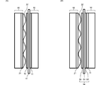
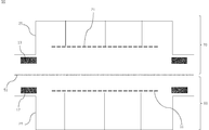
- FIG. 1 is a schematic cross-sectional view of the electrolytic cell according to the first embodiment.
- FIG. 2 is a schematic cross-sectional view showing a state in which two electrolytic cells are connected in series in the existing electrolytic cell according to the first embodiment.
- FIG. 3 is a schematic cross-sectional view illustrating a state in which two electrolytic cells are connected in series in the electrolytic cell according to the first embodiment.
- FIG. 4 is a schematic view of the electrolytic cell according to the first embodiment.
- FIG. 5 is a schematic perspective view showing a step of assembling the electrolytic cell according to the first embodiment.
- FIG. 6 is a schematic cross-sectional view of a reverse current absorber that can be provided in the electrolytic cell according to the present embodiment.
- FIG. 7 is a schematic cross-sectional view of the electrode for electrolysis in this embodiment.
- FIG. 8 is a schematic cross-sectional view illustrating the structure of the ion exchange membrane in the present embodiment.
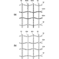
- FIG. 9 is a schematic view for explaining the aperture ratio of the reinforcing core material constituting the ion exchange membrane in the present embodiment.
- FIG. 10 is a schematic diagram for explaining a method of forming communication holes of an ion exchange membrane.
- FIG. 11 is an explanatory diagram illustrating one aspect of the method for manufacturing an electrolytic cell according to the first embodiment.
- FIG. 12 is an explanatory diagram illustrating another aspect of the method for manufacturing the electrolytic cell according to the first embodiment.
- FIG. 13 is an explanatory diagram illustrating still another aspect of the method for manufacturing an electrolytic cell according to the first embodiment.
- FIG. 14 is an explanatory diagram illustrating still another aspect of the method for manufacturing an electrolytic cell according to the first embodiment.
- FIG. 15 is a schematic cross-sectional view of the electrolytic cell according to the second embodiment.
- FIG. 16 is a schematic view of the electrolytic cell according to the second embodiment.
- FIG. 17 is a schematic perspective view showing a step of assembling the electrolytic cell according to the second embodiment.
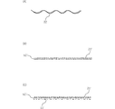
- FIG. 18 is a schematic view of members used in the method for manufacturing an electrolytic cell according to the second embodiment.
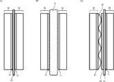
- FIG. 18A is a schematic view of the elastic body.
- FIG. 18B is a schematic view of a laminate of the first electrolysis electrode and the diaphragm.
- FIG. 18C is a schematic view of a laminate of the first electrolysis electrode, the diaphragm, and the second electrolysis electrode.
- FIG. 19 is a schematic cross-sectional view illustrating an electrolytic cell obtained when one aspect of the method for manufacturing an electrolytic cell according to the second embodiment is carried out.
- FIG. 20 is a schematic cross-sectional view illustrating an electrolytic cell obtained when another aspect of the method for manufacturing an electrolytic cell according to the second embodiment is carried out.
- first embodiment the first aspect (hereinafter, also referred to as “first embodiment”) according to the present embodiment will be described in detail with reference to FIGS. 1 to 14.
- the electrolytic tank of the first embodiment (hereinafter, unless otherwise specified, "the present embodiment" in the section of ⁇ first embodiment> means the first embodiment) faces the cathode and the anode.
- the electrode for electrolysis and a second elastic body arranged between the first electrode for electrolysis and the cathode and pressing the first electrode for electrolysis in a direction toward the anode are provided.
- the first electrolytic electrode functions as a cathode electrode, and the first electrolytic electrode, the second elastic body, the cathode, and the first elastic body are electrically connected to each other.
- the second elastic body presses the first electrolytic electrode in the direction toward the anode, so that the first elastic body deteriorates and maintains a zero gap. Even if sufficient elasticity is lost, the elasticity of the second elastic body makes it possible to maintain the zero gap, and it is not necessary to remove and replace the first elastic body itself. Further, even if the second elastic body deteriorates and loses sufficient elasticity to maintain the zero gap, the second elastic body is sandwiched between adjacent members, so that the second elastic body is sandwiched.
- the second elastic body itself can be easily replaced with a new one simply by releasing.
- the first electrode for electrolysis functions as the cathode electrode, so that it is not necessary to remove or replace the cathode itself.
- the first electrolysis electrode deteriorates and the electrolysis performance deteriorates, since the first electrolysis electrode is sandwiched between adjacent members, it is easy to simply release the sandwiching.
- the first electrolytic electrode can be replaced with a new one. Therefore, according to the electrolytic cell of the present embodiment, complicated work at the time of electrode renewal in the electrolytic cell can be avoided.
- a combination of an anode chamber including an anode and a cathode chamber including a cathode is referred to as an electrolytic cell, and each member will be described in detail below.
- FIG. 1 is a cross-sectional view of the electrolytic cell 50.
- the electrolytic cell 50 was installed in the anode chamber 60, the cathode chamber 70, the partition wall 80 installed between the anode chamber 60 and the cathode chamber 70, the anode 11 installed in the anode chamber 60, and the cathode chamber 70. It includes a cathode 21 and. If necessary, the reverse current absorber 18 installed in the cathode chamber may be provided.
- the anode 11 and the cathode 21 belonging to one electrolytic cell 50 are electrically connected to each other.
- the electrolytic cell 50 includes the following cathode structure.
- the cathode structure 90 includes a cathode chamber 70, a cathode 21 installed in the cathode chamber 70, and a reverse current absorber 18 installed in the cathode chamber 70, and the reverse current absorber 18 is shown in FIG. As shown, it has a base material 18a and a reverse current absorption layer 18b formed on the base material 18a, and the cathode 21 and the reverse current absorption layer 18b are electrically connected to each other.
- the cathode chamber 70 further includes a current collector 23, a support 24 that supports the current collector, and a first elastic body 22 that is a metal elastic body.
- the first elastic body 22 is installed between the current collector 23 and the cathode 21.
- the support 24 is installed between the current collector 23 and the partition wall 80.
- the current collector 23 is electrically connected to the cathode 21 via the first elastic body 22.
- the partition wall 80 is electrically connected to the current collector 23 via the support body 24. Therefore, the partition wall 80, the support 24, the current collector 23, the first elastic body 22, and the cathode 21 are electrically connected.
- the cathode 21 and the reverse current absorption layer 18b are electrically connected.
- the cathode 21 and the reverse current absorption layer may be directly connected, or may be indirectly connected via a current collector, a support, a metal elastic body, a partition wall, or the like.
- the entire surface of the cathode 21 is preferably coated with a catalyst layer for the reduction reaction.
- the partition wall 80 and the support 24, the support 24 and the current collector 23, and the current collector 23 and the first elastic body 22 are directly attached to each other and are mounted on the first elastic body 22.
- the cathode 21 may be laminated. As a method of directly attaching each of these constituent members to each other, welding or the like can be mentioned. Further, the reverse current absorber 18, the cathode 21, and the current collector 23 may be collectively referred to as the cathode structure 90.
- FIG. 2 is a cross-sectional view of two adjacent electrolytic cells 50 in the electrolytic cell before assembling the electrolytic cell of the present embodiment.
- FIG. 3 is a cross-sectional view of two adjacent electrolytic cells 50 in the electrolytic cell 4 of the present embodiment.
- FIG. 4 shows the electrolytic cell 4 of the present embodiment.
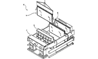
- FIG. 5 shows a process of assembling the electrolytic cell 4.
- the electrolytic cell 50, the cation exchange membrane 51, and the electrolytic cell 50 are arranged in series in this order.
- a cation exchange membrane 51 is arranged between the anode chamber of one electrolytic cell 50 and the cathode chamber of the other electrolytic cell 50 of the two adjacent electrolytic cells. That is, the anode chamber 60 of the electrolytic cell 50 and the cathode chamber 70 of the electrolytic cell 50 adjacent thereto are separated by a cation exchange membrane 51.
- the electrolytic cell 4 is composed of a plurality of electrolytic cells 50 connected in series via a cation exchange membrane 51.
- the electrolytic cell 4 is a bipolar electrolytic cell including a plurality of electrolytic cells 50 arranged in series and a cation exchange membrane 51 arranged between adjacent electrolytic cells 50. As shown in FIG. 5, the electrolytic cell 4 is assembled by arranging a plurality of electrolytic cells 50 in series via a cation exchange membrane 51 and connecting them by a press device 5.
- a first electrolysis electrode 53 is arranged between the cation exchange membrane 51 and the electrolysis cell 50 on the left side thereof in the electrolytic cell 4. That is, the first electrolysis electrode 53 is arranged between the cathode 21 and the cation exchange membrane 51 and functions as a cathode electrode.
- a second elastic body 22' is arranged between the first electrolysis electrode 53 and the cathode 21. As described above, in the electrolytic cell of the present embodiment, the second elastic body 22'presses the first electrolytic electrode 53 in the direction toward the anode 11, so that the first elastic body 22 deteriorates.
- the elasticity of the second elastic body 22' makes it possible to maintain the zero gap, and it is necessary to remove and replace the first elastic body 22 itself. Is gone. Further, even if the second elastic body 22'deteriorates and loses sufficient elasticity to maintain the zero gap, the second elastic body 22'is sandwiched between adjacent members. Therefore, the second elastic body itself can be easily replaced with a new one only by releasing the pinching.
- the first electrode for electrolysis 53 functions as a cathode electrode, so that it is not necessary to remove or replace the cathode 21 itself. Further, even if the first electrolysis electrode 53 deteriorates and the electrolysis performance deteriorates, since the first electrolysis electrode 53 is sandwiched between adjacent members, the sandwiching is only released. The first electrolytic electrode can be easily replaced with a new one.
- FIG. 3B A preferable structure of the electrolytic cell of the present embodiment will be described with reference to FIG. 3 (B).
- the first electrolysis electrode 53, the cation exchange membrane 51, and the second A laminate 54 with the electrode 53'for electrolysis is arranged in the electrolytic cell 4. That is, the first electrolysis electrode 53 is arranged between the cathode 21 and the cation exchange film 51 and functions as a cathode electrode, while the second electrolysis electrode 53'has an anode 11 and a cation exchange film. It is arranged between 51 and functions as an anode electrode. Further, as shown in FIG.
- a second elastic body 22' is arranged between the first electrolysis electrode 53 and the cathode 21. Even in such an electrolytic cell, the second elastic body 22'presses the first electrolytic electrode 53 in the direction toward the anode 11, so that the first elastic body 22 deteriorates to create a zero gap. Even if sufficient elasticity is lost to maintain, the elasticity of the second elastic body 22'makes it possible to maintain the zero gap, eliminating the need to remove and replace the first elastic body 22 itself. Further, even if the second elastic body 22'deteriorates and loses sufficient elasticity to maintain the zero gap, the second elastic body 22'is sandwiched between adjacent members. Therefore, the second elastic body itself can be easily replaced with a new one only by releasing the pinching.
- the first electrode for electrolysis 53 functions as a cathode electrode, so that it is not necessary to remove or replace the cathode 21 itself. Further, even if the first electrolysis electrode 53 deteriorates and the electrolysis performance deteriorates, since the first electrolysis electrode 53 is sandwiched between adjacent members, the sandwiching is only released. The first electrolytic electrode can be easily replaced with a new one. Further, even when the anode 11 is deteriorated, the second electrolytic electrode 53'functions as an anode electrode, so that it is not necessary to remove or replace the anode 11 itself.
- the second electrolysis electrode 53' Even if the second electrolysis electrode 53'deteriorates and the electrolysis performance deteriorates, the second electrolysis electrode 53'is sandwiched between adjacent members, so that the sandwiching is released.
- the second electrolytic electrode can be easily replaced with a new one simply by doing so.
- the electrolytic cell 4 has an anode terminal 7 and a cathode terminal 6 connected to a power source.
- the anode 11 of the electrolytic cell 50 located at the end of the plurality of electrolytic cells 50 connected in series in the electrolytic cell 4 is electrically connected to the anode terminal 7.
- the cathode 21 of the electrolytic cell located at the opposite end of the anode terminal 7 is electrically connected to the cathode terminal 6. The current during electrolysis flows from the anode terminal 7 side toward the cathode terminal 6 via the anode and the cathode of each electrolytic cell 50.
- An electrolytic cell having only an anode chamber (anode terminal cell) and an electrolytic cell having only a cathode chamber (cathode terminal cell) may be arranged at both ends of the connected electrolytic cell 50.
- the anode terminal 7 is connected to the anode terminal cell arranged at one end thereof
- the cathode terminal 6 is connected to the cathode terminal cell arranged at the other end.
- salt water is supplied to each anode chamber 60, and pure water or a low-concentration sodium hydroxide aqueous solution is supplied to the cathode chamber 70.
- Each liquid is supplied to each electrolytic cell 50 from an electrolytic solution supply pipe (omitted in the figure) via an electrolytic solution supply hose (omitted in the figure). Further, the electrolytic solution and the product obtained by electrolysis are recovered from the electrolytic solution recovery tube (omitted in the figure).
- sodium ions in salt water move from the anode chamber 60 of one electrolytic cell 50 to the cathode chamber 70 of the adjacent electrolytic cell 50 through the cation exchange membrane 51. Therefore, the current during electrolysis flows along the direction in which the electrolytic cells 50 are connected in series.
- the current flows from the anode chamber 60 toward the cathode chamber 70 via the cation exchange membrane 51.
- chlorine gas is generated on the anode 11 side
- sodium hydroxide (solute) and hydrogen gas are generated on the cathode 21 side.
- the anode chamber 60 has an anode 11 or an anode feeder 11.
- the feeding body referred to here means a deteriorated electrode (that is, an existing electrode), an electrode that is not coated with a catalyst, or the like.
- the 11 functions as an anode feeder.
- the electrode for electrolysis in the present embodiment is not inserted into the anode side, 11 functions as an anode.
- the anode chamber 60 is arranged above the anode-side electrolyte supply section for supplying the electrolyte solution to the anode chamber 60 and the anode-side electrolyte supply section, and is arranged so as to be substantially parallel to or oblique to the partition wall 80. It is preferable to have a baffle plate and an anode-side gas-liquid separation portion which is arranged above the baffle plate and separates the gas from the electrolytic solution mixed with the gas.
- the anode 11 is provided in the frame (that is, the anode frame) of the anode chamber 60.
- a metal electrode such as a so-called DSA (registered trademark) can be used.
- DSA is a titanium-based electrode whose surface is coated with an oxide containing ruthenium, iridium, and titanium as components.
- any of punching metal, non-woven fabric, foamed metal, expanded metal, perforated metal foil formed by electroforming, so-called woven mesh made by knitting a metal wire, and the like can be used.
- the anode feeding body 11 When the electrode for electrolysis in the present embodiment is inserted into the anode side, the anode feeding body 11 is provided in the frame of the anode chamber 60.
- a metal electrode such as a so-called DSA (registered trademark) can be used, or titanium without a catalyst coating can be used. It is also possible to use a DSA having a reduced catalyst coating thickness. Furthermore, a used anode can also be used.
- any of punching metal, non-woven fabric, foamed metal, expanded metal, perforated metal foil formed by electroforming, so-called woven mesh made by knitting a metal wire, and the like can be used.
- the anode-side electrolytic solution supply unit supplies the electrolytic solution to the anode chamber 60, and is connected to the electrolytic solution supply pipe.
- the anode-side electrolyte supply unit is preferably arranged below the anode chamber 60.
- a pipe dispenser pipe having an opening formed on the surface can be used. More preferably, such pipes are arranged along the surface of the anode 11 and parallel to the bottom 19 of the electrolytic cell. This pipe is connected to an electrolytic solution supply pipe (liquid supply nozzle) that supplies the electrolytic solution into the electrolytic cell 50.
- the electrolytic solution supplied from the liquid supply nozzle is conveyed into the electrolytic cell 50 by a pipe, and is supplied to the inside of the anode chamber 60 through an opening provided on the surface of the pipe.
- the electrolytic solution can be uniformly supplied to the inside of the anode chamber 60, which is preferable.
- the anode-side gas-liquid separation section is preferably arranged above the baffle plate.
- the gas-liquid separation section on the anode side has a function of separating the generated gas such as chlorine gas and the electrolytic solution.
- "upper” means an upward direction in the electrolytic cell 50 of FIG. 1
- “downward” means a downward direction in the electrolytic cell 50 of FIG.
- the electrolytic cell 50 in the present embodiment is provided with an anode-side gas-liquid separation portion for separating gas and liquid. It is preferable that a defoaming plate for eliminating air bubbles is installed in the gas-liquid separation portion on the anode side. When the gas-liquid multiphase flow passes through the defoaming plate, the bubbles burst, so that the electrolytic solution and the gas can be separated. As a result, vibration during electrolysis can be prevented.
- the baffle plate is arranged above the anode-side electrolyte supply unit and is arranged substantially parallel to or diagonally to the partition wall 80.
- the baffle plate is a partition plate that controls the flow of the electrolytic solution in the anode chamber 60.
- the electrolytic solution salt water or the like
- the baffle plate is preferably arranged so as to separate the space near the anode 11 and the space near the partition wall 80. From this point of view, it is preferable that the baffle plate is provided so as to face each surface of the anode 11 and the partition wall 80.
- the concentration of the electrolytic solution decreases as the electrolysis progresses, and generated gas such as chlorine gas is generated.
- generated gas such as chlorine gas is generated.
- a gas-liquid specific gravity difference is created between the space near the anode 11 partitioned by the baffle plate and the space near the partition wall 80. Utilizing this, the internal circulation of the electrolytic solution in the anode chamber 60 can be promoted, and the concentration distribution of the electrolytic solution in the anode chamber 60 can be made more uniform.
- a current collector may be separately provided inside the anode chamber 60.
- the current collector may have the same material and structure as the current collector in the cathode chamber, which will be described later. Further, in the anode chamber 60, the anode 11 itself can function as a current collector.
- the partition wall 80 is arranged between the anode chamber 60 and the cathode chamber 70.
- the partition wall 80 is sometimes called a separator and separates the anode chamber 60 and the cathode chamber 70.
- a known separator for electrolysis can be used, and examples thereof include a partition wall obtained by welding a plate made of nickel on the cathode side and titanium on the anode side.
- cathode chamber 70 In the cathode chamber 70, 21 functions as a cathode feeder when the electrode for electrolysis in the present embodiment is inserted into the cathode side, and 21 is when the electrode for electrolysis in the present embodiment is not inserted into the cathode side. Functions as a cathode.
- the cathode chamber 70 also has a cathode side electrolytic solution supply unit and a cathode side gas-liquid separation unit, similarly to the anode chamber 60. Of the respective parts constituting the cathode chamber 70, the same parts as those constituting the anode chamber 60 will not be described.
- the cathode 21 is provided in the frame (that is, the cathode frame) of the cathode chamber 70.
- the cathode 21 preferably has a nickel base material and a catalyst layer that coats the nickel base material.
- the components of the catalyst layer on the nickel substrate include Ru, C, Si, P, S, Al, Ti, V, Cr, Mn, Fe, Co, Ni, Cu, Zn, Y, Zr, Nb, Mo, Rh, Pd, Ag, Cd, In, Sn, Ta, W, Re, Os, Ir, Pt, Au, Hg, Pb, Bi, La, Ce, Pr, Nd, Pm, Sm, Eu, Gd, Tb, Examples thereof include metals such as Dy, Ho, Er, Tm, Yb and Lu, and oxides or hydroxides of the metals.
- the method for forming the catalyst layer examples include plating, alloy plating, dispersion / composite plating, CVD, PVD, thermal decomposition and thermal spraying. You may combine these methods.
- the catalyst layer may have a plurality of layers and a plurality of elements, if necessary.
- the cathode 21 may be subjected to a reduction treatment if necessary.
- nickel, nickel alloy, iron, or stainless steel plated with nickel may be used.
- any of punching metal, non-woven fabric, foamed metal, expanded metal, perforated metal foil formed by electroforming, so-called woven mesh made by knitting a metal wire, and the like can be used.
- the cathode feeding body 21 When the electrode for electrolysis in the present embodiment is inserted into the cathode side, the cathode feeding body 21 is provided in the frame of the cathode chamber 70.
- the cathode feeding body 21 may be coated with a catalyst component.
- the catalyst component may be one that was originally used as a cathode and remained.
- the components of the catalyst layer include Ru, C, Si, P, S, Al, Ti, V, Cr, Mn, Fe, Co, Ni, Cu, Zn, Y, Zr, Nb, Mo, Rh, Pd, Ag.
- the catalyst layer may have a plurality of layers and a plurality of elements, if necessary. Further, nickel, nickel alloy, iron or stainless steel which is not catalyst-coated and plated with nickel may be used.
- nickel nickel alloy, iron, or stainless steel plated with nickel may be used.
- shape any of punching metal, non-woven fabric, foamed metal, expanded metal, perforated metal foil formed by electroforming, so-called woven mesh made by knitting a metal wire, and the like can be used.
- a material having a redox potential lower than the redox potential of the element for the catalyst layer of the cathode described above can be selected as the material of the reverse current absorption layer.
- nickel and iron can be mentioned.
- the cathode chamber 70 preferably includes a current collector 23.
- the current collector 23 is a perforated plate, and it is preferable that the current collector 23 is arranged substantially parallel to the surface of the cathode 21.
- the current collector 23 is preferably made of an electrically conductive metal such as nickel, iron, copper, silver, or titanium.
- the current collector 23 may be a mixture, alloy or composite oxide of these metals.
- the shape of the current collector 23 may be any shape as long as it functions as a current collector, and may be plate-shaped or net-shaped.
- each cathode 21 of the plurality of electrolytic cells 50 connected in series is pressed against the cation exchange film 51, and each anode
- the distance between the 11 and each cathode 21 is shortened, and the voltage applied to the entire plurality of electrolytic cells 50 connected in series can be reduced. By lowering the voltage, the amount of power consumption can be reduced.
- the electrode for electrolysis is applied by the pressing pressure by the first elastic body 22. Can be stably maintained in place.
- the first elastic body 22 deteriorates with time with the long-term operation of the electrolytic cell. That is, the first elastic body 22 may have lost sufficient elasticity to maintain the zero gap due to deterioration. Even if the first elastic body 22 is deteriorated in this way, in the present embodiment, the zero gap can be maintained by the elasticity of the second elastic body.
- first elastic body 22 and the second elastic body 22' a spiral spring, a spring member such as a coil, a cushioning mat, or the like can be used. Further, as the first elastic body 22 and the second elastic body 22', suitable ones can be appropriately adopted in consideration of the stress of pressing the ion exchange membrane and the like.
- the first elastic body 22 may be provided on the surface of the current collector 23 on the cathode chamber 70 side, or may be provided on the surface of the partition wall on the anode chamber 60 side. Normally, both chambers are partitioned so that the cathode chamber 70 is smaller than the anode chamber 60.
- the first elastic body 22 is the current collector 23 and the cathode 21 of the cathode chamber 70. It is preferable to provide it between. Further, the first elastic body 22 and the second elastic body 22'preferably made of a metal having electrical conductivity such as nickel, iron, copper, silver and titanium. In the present embodiment, the first elastic body 22 and the second elastic body 22'may have the same shape, material and physical characteristics from each other, or may be different from each other.
- the thickness of the second elastic body is set to that of the first elastic body from the viewpoint of effectively preventing the loss of the zero gap structure due to the deterioration of the first elastic body. It is preferably larger than the thickness. From the same viewpoint as described above, it is preferable that the working surface pressure of the second elastic body is larger than the working surface pressure of the first elastic body.
- the thickness of the first elastic body and the thickness of the second elastic body are not particularly limited, and both can be, for example, 0.1 mm to 15 mm, preferably 0.2 mm to 10 mm, more preferably. Is 0.5 mm to 7 mm.
- conventional surface pressure of the first conventional surface of the elastic body pressure and a second elastic member is not particularly limited, either, can be, for example 30gf / cm 2 ⁇ 350gf / cm 2, preferably 40 ⁇ was 300 gf / cm 2, more preferably 50 ⁇ 250gf / cm 2.
- the cathode chamber 70 preferably includes a support 24 that electrically connects the current collector 23 and the partition wall 80. This makes it possible to efficiently pass an electric current.
- the support 24 is preferably made of a metal having electrical conductivity such as nickel, iron, copper, silver, and titanium.
- the shape of the support 24 may be any shape as long as it can support the current collector 23, and may be rod-shaped, plate-shaped, or net-shaped.
- the support 24 has, for example, a plate shape.
- the plurality of supports 24 are arranged between the partition wall 80 and the current collector 23.
- the plurality of supports 24 are arranged so that their surfaces are parallel to each other.
- the support 24 is arranged substantially perpendicular to the partition wall 80 and the current collector 23.
- the anode side gasket 12 is preferably arranged on the surface of the frame forming the anode chamber 60.
- the cathode side gasket 13 is preferably arranged on the surface of the frame forming the cathode chamber 70.
- the electrolytic cells are connected to each other so that the anode-side gasket 12 included in one electrolytic cell and the cathode-side gasket 13 of the electrolytic cell adjacent thereto sandwich the cation exchange membrane 51 (see FIG. 2). With these gaskets, when a plurality of electrolytic cells 50 are connected in series via the cation exchange membrane 51, airtightness can be imparted to the connection points.
- the gasket is a seal between the ion exchange membrane and the electrolytic cell.
- Specific examples of the gasket include a frame-shaped rubber sheet having an opening formed in the center.
- the gasket is required to have resistance to corrosive electrolytes, generated gases, and the like, and to be able to be used for a long period of time. Therefore, from the viewpoint of chemical resistance and hardness, vulcanized products of ethylene / propylene / diene rubber (EPDM rubber), vulcanized products of ethylene / propylene rubber (EPM rubber), cross-linked peroxide products, etc. are usually used as gaskets.
- EPDM rubber ethylene / propylene / diene rubber
- EPM rubber vulcanized products of ethylene / propylene rubber
- cross-linked peroxide products, etc. are usually used as gaskets.
- a gasket in which the region in contact with the liquid (contact portion) is coated with a fluororesin such as polytetrafluoroethylene (PTFE) or tetrafluoroethylene / perfluoroalkyl vinyl ether copolymer (PFA). You can also.
- PTFE polytetrafluoroethylene
- PFA perfluoroalkyl vinyl ether copolymer
- Each of these gaskets may have an opening so as not to obstruct the flow of the electrolytic solution, and the shape thereof is not particularly limited.
- a frame-shaped gasket is attached with an adhesive or the like along the peripheral edge of each opening of the anode chamber frame forming the anode chamber 60 or the cathode chamber frame forming the cathode chamber 70.
- each electrolytic cell 50 to which a gasket is attached may be tightened via the cation exchange membrane 51.
- the electrolytic solution, the alkali metal hydroxide, chlorine gas, hydrogen gas and the like generated by electrolysis from leaking to the outside of the electrolytic cell 50.
- the electrode for electrolysis in this embodiment can be used as a laminate with a diaphragm such as an ion exchange membrane or a microporous membrane. That is, the laminate in the present embodiment may include a first electrolysis electrode and a diaphragm, or may include a first electrolysis electrode, a diaphragm, and a second electrolysis electrode. May be good. Specific examples of the electrode for electrolysis and the diaphragm will be described in detail below.
- the electrode for electrolysis in the present embodiment is not particularly limited, but is preferably one that can form a diaphragm and a laminate as described above, that is, one that can be integrated with the diaphragm, and is used as a wound body. More preferably.
- the electrode for electrolysis may function as a cathode in the electrolytic cell, or may function as an anode. Further, regarding the material, shape, physical properties, etc. of the electrode for electrolysis, an appropriate one can be appropriately selected in consideration of the steps (A) and (B) in the present embodiment described later, the configuration of the electrolytic cell, and the like.
- the electrode for electrolysis in the present embodiment has good handleability and has good adhesion to a diaphragm such as an ion exchange membrane or a microporous membrane, a feeder (deteriorated electrode and an electrode not coated with a catalyst), and the like.
- the applied force per unit mass / unit area is preferably 1.6 N / (mg ⁇ cm 2 ) or less, more preferably less than 1.6 N / (mg ⁇ cm 2 ), and further. It is preferably less than 1.5 N / (mg ⁇ cm 2 ), even more preferably 1.2 N / mg ⁇ cm 2 or less, and even more preferably 1.20 N / mg ⁇ cm 2 or less.
- the applied force can be set within the above range by appropriately adjusting, for example, the pore size, the thickness of the electrode, the arithmetic mean surface roughness, etc., which will be described later. More specifically, for example, when the opening ratio is increased, the applied force tends to be small, and when the opening ratio is decreased, the applied force tends to be large.
- the mass per unit area is preferably 48 mg / cm 2 or less, more preferably 30 mg / cm 2 or less, further preferably 20 mg / cm 2 or less, and further, handleability and adhesiveness. From a comprehensive viewpoint including economic efficiency, it is preferably 15 mg / cm 2 or less.
- the lower limit is not particularly limited, but is, for example, about 1 mg / cm 2.
- the mass per unit area can be set within the above range by, for example, appropriately adjusting the pore size, the thickness of the electrode, and the like, which will be described later. More specifically, for example, if the thickness is the same, increasing the opening ratio tends to reduce the mass per unit area, and decreasing the opening ratio tends to increase the mass per unit area. be.
- Such force can be measured by the following method (i) or (ii).
- the applied force is a value obtained by the measurement of the method (i) (also referred to as “applied force (1)”) and a value obtained by the measurement of the method (ii) (also referred to as “applied force (2)"). Although they may be the same or different, it is preferable that the value is less than 1.5 N / mg ⁇ cm 2 regardless of the value.
- the specific calculation method of the arithmetic mean surface roughness (Ra) is as described in the examples. Under the conditions of a temperature of 23 ⁇ 2 ° C. and a relative humidity of 30 ⁇ 5%, only the electrode sample in this measurement sample was raised in the vertical direction at 10 mm / min using a tensile compression tester to obtain an electrode sample. The weight when it rises 10 mm in the vertical direction is measured. This measurement is performed three times to calculate the average value. Dividing this average value by the area of the overlapping portion of the electrode sample and the ion exchange membrane and the mass of the electrode sample of the portion overlapping the ion exchange membrane, the applied force per unit mass / unit area (1) (N) / Mg ⁇ cm 2 ) is calculated.
- the applied force (1) per unit mass / unit area obtained by the method (i) has good handleability, and is coated with a diaphragm such as an ion exchange membrane or a microporous membrane, a deteriorated electrode, and a catalyst coating.
- a diaphragm such as an ion exchange membrane or a microporous membrane, a deteriorated electrode, and a catalyst coating.
- it is preferably 1.6 N / (mg ⁇ cm 2 ) or less, more preferably less than 1.6 N / (mg ⁇ cm 2 ), and further. It is preferably less than 1.5 N / (mg ⁇ cm 2 ), even more preferably 1.2 N / mg ⁇ cm 2 or less, and even more preferably 1.20 N / mg ⁇ cm 2 or less.
- This measurement is performed three times to calculate the average value.
- This average value is divided by the area of the overlapping portion of the electrode sample and the nickel plate and the mass of the electrode sample in the overlapping portion of the nickel plate, and the adhesive force per unit mass / unit area (2) (N / mg). ⁇ Calculate cm 2 ).
- the applied force (2) per unit mass / unit area obtained by the method (ii) has good handleability, and is coated with a diaphragm such as an ion exchange membrane or a microporous membrane, a deteriorated electrode, and a catalyst coating.
- a diaphragm such as an ion exchange membrane or a microporous membrane, a deteriorated electrode, and a catalyst coating.
- it is preferably 1.6 N / (mg ⁇ cm 2 ) or less, more preferably less than 1.6 N / (mg ⁇ cm 2 ), and further. It is preferably less than 1.5 N / (mg ⁇ cm 2 ), even more preferably 1.2 N / mg ⁇ cm 2 or less, and even more preferably 1.20 N / mg ⁇ cm 2 or less.
- the electrode for electrolysis in this embodiment preferably includes an electrode base material for electrolysis and a catalyst layer.
- the thickness (gauge thickness) of the electrode base material for electrolysis is not particularly limited, but good handleability is obtained, and a diaphragm such as an ion exchange membrane or a microporous membrane, a deteriorated electrode (feeding body), and a catalyst coating are applied. It has good adhesion to the electrode (feeding body) that has not been used, can be rolled into a suitable roll, can be bent well, and can be easily handled in a large size (for example, size 1.5m x 2.5m).
- 300 ⁇ m or less is preferable, 205 ⁇ m or less is more preferable, 155 ⁇ m or less is further preferable, 135 ⁇ m or less is further more preferable, 125 ⁇ m or less is further more preferable, 120 ⁇ m or less is further preferable, and 100 ⁇ m or less is further preferable. From the viewpoint of handleability and economy, 50 ⁇ m or less is even more preferable.
- the lower limit is not particularly limited, but is, for example, 1 ⁇ m, preferably 5 ⁇ m, and more preferably 15 ⁇ m.
- a liquid is interposed between them.
- the liquid can be any liquid such as water and an organic solvent as long as it generates surface tension.
- the greater the surface tension of the liquid the greater the force applied between the diaphragm and the electrode for electrolysis. Therefore, a liquid having a large surface tension is preferable.
- Examples of the liquid include the following (the numerical value in parentheses is the surface tension of the liquid at 20 ° C.).
- a liquid having a surface tension of 24 mN / m to 80 mN / m such as ethanol, ethylene glycol, and water.
- a liquid having a surface tension of 24 mN / m to 80 mN / m such as ethanol, ethylene glycol, and water.
- water or an aqueous solution obtained by dissolving caustic soda, potassium hydroxide, lithium hydroxide, sodium hydrogencarbonate, potassium hydrogencarbonate, sodium carbonate, potassium carbonate or the like in water to make it alkaline is preferable. It is also possible to add a surfactant to these liquids to adjust the surface tension.
- the surfactant By including the surfactant, the adhesiveness between the diaphragm and the electrode for electrolysis is changed, and the handleability can be adjusted.
- the surfactant is not particularly limited, and either an ionic surfactant or a nonionic surfactant can be used.
- the electrode for electrolysis in the present embodiment is not particularly limited, but good handleability is obtained, and a diaphragm such as an ion exchange membrane or a microporous membrane, a deteriorated electrode (feeding body), and an electrode without catalyst coating (feeding) are obtained.
- the ratio measured by the following method (2) is preferably 90% or more, more preferably 92% or more, and further, a large size (body). For example, it is more preferably 95% or more from the viewpoint of facilitating handling in a size of 1.5 m ⁇ 2.5 m).
- the upper limit is 100%.
- Method (2) The ion exchange membrane (170 mm square) and the electrode sample (130 mm square) are laminated in this order. Under the conditions of a temperature of 23 ⁇ 2 ° C. and a relative humidity of 30 ⁇ 5%, the laminate is placed on the curved surface of a polyethylene pipe (outer diameter 280 mm) so that the electrode sample in the laminate is on the outside. And the pipe are sufficiently immersed in pure water to remove excess water adhering to the surface of the laminate and the pipe, and one minute later, the portion where the ion exchange membrane (170 mm square) and the electrode sample are in close contact with each other. Measure the percentage of the area of.
- the electrode for electrolysis in the present embodiment is not particularly limited, but good handleability is obtained, and a diaphragm such as an ion exchange membrane or a microporous membrane, a deteriorated electrode (feeding body), and an electrode without catalyst coating (feeding) are obtained.
- a diaphragm such as an ion exchange membrane or a microporous membrane, a deteriorated electrode (feeding body), and an electrode without catalyst coating (feeding) are obtained.
- the ratio measured by the following method (3) is preferably 75% or more. It is more preferably 80% or more, and further preferably 90% or more from the viewpoint of facilitating handling in a large size (for example, size 1.5 m ⁇ 2.5 m).
- the upper limit is 100%.
- Method (3) The ion exchange membrane (170 mm square) and the electrode sample (130 mm square) are laminated in this order. Under the conditions of a temperature of 23 ⁇ 2 ° C. and a relative humidity of 30 ⁇ 5%, the laminate is placed on a curved surface of a polyethylene pipe (outer diameter of 145 mm) so that the electrode sample in the laminate is on the outside. And the pipe are sufficiently immersed in pure water to remove excess water adhering to the surface of the laminate and the pipe, and one minute later, the portion where the ion exchange membrane (170 mm square) and the electrode sample are in close contact with each other. Measure the percentage of the area of.
- the electrode for electrolysis in the present embodiment is not particularly limited, but good handleability is obtained, and a diaphragm such as an ion exchange membrane or a microporous membrane, a deteriorated electrode (feeding body), and an electrode without catalyst coating (feeding) are obtained. It has a good adhesive force with the body), and from the viewpoint of preventing the retention of gas generated during electrolysis, it is preferably a porous structure having a porosity or porosity of 5 to 90% or less.
- the opening rate is more preferably 10 to 80% or less, still more preferably 20 to 75%.
- the opening rate is the ratio of the opening portion per unit volume. There are various calculation methods depending on whether the opening portion is also considered to the submicron order or only the visible opening is considered.
- the opening ratio A can be calculated by the following formula by calculating the volume V from the values of the gauge thickness, width, and length of the electrode and further measuring the weight W.
- A (1- (W / (V ⁇ ⁇ )) ⁇ 100 ⁇ is the density of the electrode material (g / cm 3 ).
- the pore size can be adjusted by changing the area where the metal is punched per unit area for punching metal, changing the SW (minor diameter), LW (major diameter), and feed values for expanded metal.
- change the wire diameter and number of meshes of metal fibers change the pattern of the photoresist used for electroforming, change the metal fiber diameter and fiber density for non-woven materials, and form voids for foamed metals. It can be appropriately adjusted by a method such as changing the mold for making the metal.
- the electrode for electrolysis in the present embodiment preferably has a value measured by the following method (A) of 40 mm or less, more preferably 29 mm or less, and further preferably 10 mm or less. , Even more preferably 6.5 mm or less.
- Method (A) Under the conditions of a temperature of 23 ⁇ 2 ° C. and a relative humidity of 30 ⁇ 5%, a sample of a laminated body in which an ion exchange membrane and the electrode for electrolysis are laminated is wound around a curved surface of a vinyl chloride core material having an outer diameter of ⁇ 32 mm.
- the electrode for electrolysis After fixing and allowing to stand for 6 hours, when the electrode for electrolysis was separated and placed on a horizontal plate, the heights L 1 and L 2 in the vertical direction at both ends of the electrode for electrolysis were measured, and these were measured. Let the average value of be the measured value.
- the electrolysis electrode in the present embodiment has a size of 50 mm ⁇ 50 mm, a temperature of 24 ° C., a relative humidity of 32%, a piston speed of 0.2 cm / s, and an air flow rate of 0.4 cc / cm 2 / s.
- the ventilation resistance (hereinafter, also referred to as “ventilation resistance 1”) in the case (hereinafter, also referred to as “measurement condition 1”) is preferably 24 kPa ⁇ s / m or less.
- a large ventilation resistance means that it is difficult for air to flow, and indicates a state of high density.
- the product of electrolysis stays in the electrode, and the reaction substrate is difficult to diffuse inside the electrode, so that the electrolysis performance (voltage, etc.) tends to deteriorate.
- the concentration on the film surface tends to increase.
- the caustic concentration tends to increase on the cathode surface, and the supply of salt water tends to decrease on the anode surface.
- the product stays at a high concentration at the interface where the diaphragm and the electrode for electrolysis are in contact with each other, which tends to lead to damage to the diaphragm, resulting in voltage rise and membrane damage on the cathode surface, and membrane damage on the anode surface. It is in.
- the ventilation resistance is 24 kPa ⁇ s / m or less. From the same viewpoint as described above, it is more preferably less than 0.19 kPa ⁇ s / m, further preferably 0.15 kPa ⁇ s / m or less, and even more preferably 0.07 kPa ⁇ s / m or less. preferable. If the aeration resistance is larger than a certain level, NaOH generated at the electrode tends to stay at the interface between the electrode for electrolysis and the diaphragm in the case of a cathode and tends to have a high concentration, and in the case of an anode, the salt water supply property is lowered.
- the salt water concentration tends to be low, and in order to prevent damage to the diaphragm that may occur due to such retention, it is preferably less than 0.19 kPa ⁇ s / m, which is 0. It is more preferably .15 kPa ⁇ s / m or less, and further preferably 0.07 kPa ⁇ s / m or less.
- the ventilation resistance is low, the area of the electrode for electrolysis becomes small, so that the area of electrolysis tends to be small and the electrolysis performance (voltage or the like) tends to deteriorate.
- the preferable lower limit value specified as the ventilation resistance 1 is not particularly limited, but is preferably more than 0 kPa ⁇ s / m, more preferably 0.0001 kPa ⁇ s / m or more, and further preferably 0.0001 kPa ⁇ s / m or more. It is 0.001 kPa ⁇ s / m or more. It should be noted that the ventilation resistance 1 may not have sufficient measurement accuracy at 0.07 kPa ⁇ s / m or less due to its measurement method.
- the ventilation resistance 2 is the ventilation resistance when the electrode for electrolysis has a size of 50 mm ⁇ 50 mm, the temperature is 24 ° C., the relative humidity is 32%, the piston speed is 2 cm / s, and the ventilation amount is 4 cc / cm 2 / s.
- the ventilation resistances 1 and 2 can be set within the above range by, for example, appropriately adjusting the pore size, the thickness of the electrode, and the like, which will be described later. More specifically, for example, if the thickness is the same, increasing the opening ratio tends to decrease the ventilation resistances 1 and 2, and decreasing the opening ratio tends to increase the ventilation resistances 1 and 2. be.
- the electrode for electrolysis in the present embodiment preferably includes an electrode base material for electrolysis and a catalyst layer.
- the catalyst layer may be composed of a plurality of layers or may have a single-layer structure as described below.
- the electrolysis electrode 101 according to the present embodiment includes an electrolysis electrode base material 10 and a pair of first layers 20 that cover both surfaces of the electrolysis electrode base material 10.
- the first layer 20 preferably covers the entire electrode base material 10 for electrolysis. This makes it easier to improve the catalytic activity and durability of the electrode for electrolysis.
- the first layer 20 may be laminated only on one surface of the electrode base material 10 for electrolysis. Further, as shown in FIG. 7, the surface of the first layer 20 may be covered with the second layer 30.
- the second layer 30 preferably covers the entire first layer 20. Further, the second layer 30 may be laminated on only one surface of the first layer 20.
- the electrode base material 10 for electrolysis is not particularly limited, and for example, a valve metal typified by nickel, nickel alloy, stainless steel, titanium, etc. can be used, and from nickel (Ni) and titanium (Ti). It preferably contains at least one element of choice. Considering that iron and chromium elute when stainless steel is used in a high-concentration alkaline aqueous solution, and that the electrical conductivity of stainless steel is about 1/10 that of nickel, it can be used as an electrode base material for electrolysis. A base material containing nickel (Ni) is preferable.
- the electrode base material 10 for electrolysis is made of titanium having high corrosion resistance when used in a chlorine gas generating atmosphere in a salt solution having a concentration close to saturation.
- the shape of the electrode base material 10 for electrolysis is not particularly limited, and an appropriate shape can be selected depending on the intended purpose. As the shape, any of punching metal, non-woven fabric, foamed metal, expanded metal, perforated metal foil formed by electroforming, so-called woven mesh made by knitting a metal wire, and the like can be used. Of these, punching metal or expanded metal is preferable. Electroforming is a technique for producing a metal thin film having a precise pattern by combining photoengraving and electroplating.
- the shape of the electrode base material for electrolysis there are suitable specifications depending on the distance between the anode and the cathode in the electrolytic cell. Although not particularly limited, when the anode and the cathode have a finite distance, an expanded metal or punching metal shape can be used, and in the case of a so-called zero gap electrolytic cell in which the ion exchange film and the electrode are in contact with each other. Woven mesh woven with fine wires, wire mesh, foamed metal, metal non-woven fabric, expanded metal, punching metal, perforated metal foil and the like can be used.
- the electrode base material 10 for electrolysis examples include a metal porous foil, a wire mesh, a metal non-woven fabric, a punching metal, an expanded metal, and a foamed metal.
- a rolled plate material, an electrolytic foil or the like is preferable. It is preferable that the electrolytic foil is further plated with the same element as the base material as a post-treatment to make one side or both sides uneven.
- the thickness of the electrode base material 10 for electrolysis is preferably 300 ⁇ m or less, more preferably 205 ⁇ m or less, further preferably 155 ⁇ m or less, and further preferably 135 ⁇ m or less.
- the lower limit is not particularly limited, but is, for example, 1 ⁇ m, preferably 5 ⁇ m, and more preferably 15 ⁇ m.
- the electrode base material for electrolysis it is preferable to relax the residual stress during processing by annealing the electrode base material for electrolysis in an oxidizing atmosphere. Further, in order to improve the adhesion to the catalyst layer coated on the surface of the electrode base material for electrolysis, unevenness is formed by using a steel grid, alumina powder, etc., and then the surface area is increased by acid treatment. It is preferable to increase it. Alternatively, it is preferable to perform plating treatment with the same element as the base material to increase the surface area.
- the electrode base material 10 for electrolysis is subjected to a treatment for increasing the surface area in order to bring the first layer 20 and the surface of the electrode base material 10 for electrolysis into close contact with each other.
- a treatment for increasing the surface area include a blast treatment using a cut wire, a steel grid, an alumina grid, etc., an acid treatment using sulfuric acid or hydrochloric acid, a plating treatment using the same element as the base material, and the like.
- the arithmetic mean surface roughness (Ra) of the substrate surface is not particularly limited, but is preferably 0.05 ⁇ m to 50 ⁇ m, more preferably 0.1 to 10 ⁇ m, and even more preferably 0.1 to 8 ⁇ m.
- the first layer 20 which is a catalyst layer contains at least one kind of oxide among ruthenium oxide, iridium oxide and titanium oxide.
- the ruthenium oxide include RuO 2 .
- the iridium oxide include IrO 2 .
- the titanium oxide include TiO 2 and the like.
- the first layer 20 preferably contains two types of oxides, ruthenium oxide and titanium oxide, or preferably contains three types of oxides, ruthenium oxide, iridium oxide and titanium oxide. As a result, the first layer 20 becomes a more stable layer, and the adhesion with the second layer 30 is further improved.
- the first layer 20 contains two types of oxides, ruthenium oxide and titanium oxide
- titanium oxidation contained in the first layer 20 is compared with 1 mol of ruthenium oxide contained in the first layer 20.
- the substance is preferably 1 to 9 mol, more preferably 1 to 4 mol.
- the first layer 20 contains three types of oxides, ruthenium oxide, iridium oxide, and titanium oxide, it is contained in the first layer 20 with respect to 1 mol of the ruthenium oxide contained in the first layer 20.
- the amount of iridium oxide is preferably 0.2 to 3 mol, more preferably 0.3 to 2.5 mol.
- the amount of titanium oxide contained in the first layer 20 is preferably 0.3 to 8 mol, and more preferably 1 to 7 mol, with respect to 1 mol of ruthenium oxide contained in the first layer 20. preferable.
- the first layer 20 contains at least two kinds of oxides selected from ruthenium oxide, iridium oxide and titanium oxide, these oxides preferably form a solid solution.
- oxides selected from ruthenium oxide, iridium oxide and titanium oxide.
- compositions can be used as long as they contain at least one of ruthenium oxide, iridium oxide and titanium oxide.
- an oxide coating containing ruthenium, iridium, tantalum, niobium, titanium, tin, cobalt, manganese, platinum, etc., which is called DSA (registered trademark) can be used as the first layer 20.
- the first layer 20 does not have to be a single layer, and may include a plurality of layers.
- the first layer 20 may include a layer containing three types of oxides and a layer containing two types of oxides.
- the thickness of the first layer 20 is preferably 0.05 to 10 ⁇ m, more preferably 0.1 to 8 ⁇ m.
- the second layer 30 preferably contains ruthenium and titanium. As a result, the chlorine overvoltage immediately after electrolysis can be further reduced.
- the second layer 30 contains palladium oxide, a solid solution of palladium oxide and platinum, or an alloy of palladium and platinum. As a result, the chlorine overvoltage immediately after electrolysis can be further reduced.
- the thickness of the second layer 30 is preferably 0.05 to 3 ⁇ m.
- the components of the first layer 20 which is the catalyst layer include C, Si, P, S, Al, Ti, V, Cr, Mn, Fe, Co, Ni, Cu, Zn, Y, Zr, Nb, Mo, and Ru. , Rh, Pd, Ag, Cd, In, Sn, Ta, W, Re, Os, Ir, Pt, Au, Hg, Pb, Bi, La, Ce, Pr, Nd, Pm, Sm, Eu, Gd, Tb , Dy, Ho, Er, Tm, Yb, Lu and the like, and oxides or hydroxides of the metal.
- the metal-containing alloy contains at least one platinum group metal among platinum, palladium, rhodium, ruthenium and iridium.
- the platinum group metal preferably contains platinum.
- the platinum group metal oxide preferably contains a ruthenium oxide.
- the platinum group metal hydroxide preferably contains ruthenium hydroxide.
- the platinum group metal alloy preferably contains an alloy of platinum with nickel, iron, and cobalt. Further, if necessary, it is preferable to contain an oxide or a hydroxide of a lanthanoid element as the second component. As a result, the electrode 101 for electrolysis exhibits excellent durability.
- the lanthanoid element oxide or hydroxide preferably contains at least one selected from lanthanum, cerium, praseodymium, neodymium, promethium, samarium, europium, gadolinium, terbium, and dysprosium. Further, if necessary, it is preferable to include a transition metal oxide or a hydroxide as the third component.
- the electrode 101 for electrolysis exhibits better durability and the electrolysis voltage can be reduced.
- preferred combinations are ruthenium only, ruthenium + nickel, ruthenium + cerium, ruthenium + lantern, ruthenium + lanthanum + platinum, ruthenium + lanthanum + palladium, ruthenium + placeodium, ruthenium + placeodium + platinum, ruthenium + placeodium + platinum + Palladium, ruthenium + neodymium, ruthenium + neodymium + platinum, ruthenium + neodymium + manganese, ruthenium + neodymium + iron, ruthenium + neodymium + cobalt, ruthenium + neodymium + zinc, ruthenium + neodymium + gallium, ruthenium + neodymium + sulfur, ruthenium + Neodim + lead, ruthenium + neodym
- the main component of the catalyst is a nickel element. It is preferable to contain at least one of nickel metal, oxide and hydroxide.
- a transition metal may be added as the second component.
- the second component to be added preferably contains at least one element of titanium, tin, molybdenum, cobalt, manganese, iron, sulfur, zinc, copper and carbon. Preferred combinations include nickel + tin, nickel + titanium, nickel + molybdenum, nickel + cobalt and the like. If necessary, an intermediate layer can be provided between the first layer 20 and the electrode base material 10 for electrolysis.
- the durability of the electrolytic electrode 101 can be improved.
- the intermediate layer those having an affinity for both the first layer 20 and the electrode base material 10 for electrolysis are preferable.
- nickel oxide, platinum group metal, platinum group metal oxide, and platinum group metal hydroxide are preferable.
- the intermediate layer can be formed by applying and firing a solution containing the components forming the intermediate layer, or the base material is heat-treated at a temperature of 300 to 600 ° C. in an air atmosphere to oxidize the surface. It is also possible to form a material layer. In addition, it can be formed by a known method such as a thermal spraying method or an ion plating method.
- the components of the first layer 30 which is the catalyst layer include C, Si, P, S, Al, Ti, V, Cr, Mn, Fe, Co, Ni, Cu, Zn, Y, Zr, Nb, Mo, and Ru. , Rh, Pd, Ag, Cd, In, Sn, Ta, W, Re, Os, Ir, Pt, Au, Hg, Pb, Bi, La, Ce, Pr, Nd, Pm, Sm, Eu, Gd, Tb , Dy, Ho, Er, Tm, Yb, Lu and the like, and oxides or hydroxides of the metal.
- the second layer may be a combination having the same composition but a different composition ratio, or a combination of different compositions.
- the total thickness of the formed catalyst layer and the intermediate layer is preferably 0.01 ⁇ m to 20 ⁇ m. If it is 0.01 ⁇ m or more, it can sufficiently function as a catalyst. If it is 20 ⁇ m or less, a strong catalyst layer can be formed with little loss from the substrate. More preferably, 0.05 ⁇ m to 15 ⁇ m. More preferably, it is 0.1 ⁇ m to 10 ⁇ m. More preferably, it is 0.2 ⁇ m to 8 ⁇ m.
- the thickness of the electrode that is, the total thickness of the electrode base material for electrolysis and the catalyst layer is preferably 315 ⁇ m or less, more preferably 220 ⁇ m or less, further preferably 170 ⁇ m or less, and further preferably 150 ⁇ m or less from the viewpoint of handleability of the electrode. More preferably, 145 ⁇ m or less is particularly preferable, 140 ⁇ m or less is further preferable, 138 ⁇ m or less is further preferable, and 135 ⁇ m or less is even more preferable. If it is 135 ⁇ m or less, particularly good handleability can be obtained.
- the thickness of the electrode can be determined by measuring with a Digimatic Sixness Gauge (Mitutoyo Co., Ltd., minimum display 0.001 mm). The thickness of the electrode base material for electrodes is measured in the same manner as the electrode thickness. The catalyst layer thickness can be obtained by subtracting the thickness of the electrode base material for electrolysis from the electrode thickness.
- the electrodes for electrolysis include Ru, Rh, Pd, Ir, Pt, Au, Ti, V, Cr, Mn, Fe, Co, Ni, Cu, Zn, Y, Zr, Nb, Mo, Ag, Ta, W, Re, Os, Al, In, Sn, Sb, Ga, Ge, B, C, N, O, Si, P, S, La, Ce, Pr, It preferably contains at least one catalytic component selected from the group consisting of Nd, Pm, Sm, Eu, Gd, Tb and Dy.
- the electrode for electrolysis when the electrode for electrolysis is an electrode having a wide elastic deformation region, better handleability can be obtained, and a diaphragm such as an ion exchange membrane or a microporous membrane, a deteriorated electrode, and a catalyst coating are not applied.
- the thickness of the electrode for electrolysis is preferably 315 ⁇ m or less, more preferably 220 ⁇ m or less, further preferably 170 ⁇ m or less, further preferably 150 ⁇ m or less, and particularly preferably 145 ⁇ m or less. , 140 ⁇ m or less is more preferable, 138 ⁇ m or less is further preferable, and 135 ⁇ m or less is even more preferable.
- the elastic deformation region is wide means that the electrolytic electrode is wound to form a wound body, and after the wound state is released, warpage due to the winding is unlikely to occur. ..
- the thickness of the electrode for electrolysis means the total thickness of the electrode base material for electrolysis and the catalyst layer when the catalyst layer described later is included.
- the first electrode for electrolysis among the electrodes for electrolysis having the above-mentioned materials, shapes, physical characteristics, etc., those that function as a cathode can be appropriately selected and used.
- the second electrode for electrolysis among the electrodes for electrolysis having the above-mentioned materials, shapes, physical properties, etc., those that function as an anode can be appropriately selected and used.
- the first layer 20, preferably the second layer is placed on the electrode base material for electrolysis by a method such as firing (pyrolysis) of the coating film in an oxygen atmosphere, ion plating, plating, or thermal spraying.
- a method such as firing (pyrolysis) of the coating film in an oxygen atmosphere, ion plating, plating, or thermal spraying.
- the electrode 101 for electrolysis can be manufactured.
- high productivity of the electrode 101 for electrolysis can be realized.
- a catalyst layer is formed on the electrode base material for electrolysis by a coating step of applying a coating liquid containing a catalyst, a drying step of drying the coating liquid, and a thermal decomposition step of performing thermal decomposition.
- thermal decomposition means that a metal salt as a precursor is heated and decomposed into a metal or a metal oxide and a gaseous substance.
- Decomposition products differ depending on the type of metal used, the type of salt, the atmosphere in which thermal decomposition is performed, etc., but many metals tend to form oxides in an oxidizing atmosphere.
- pyrolysis is usually carried out in air, often forming metal oxides or metal hydroxides.
- first layer 20 (Applying process)
- a solution (first coating liquid) in which at least one metal salt of ruthenium, iridium and titanium is dissolved is applied to an electrode base material for electrolysis, and then thermally decomposed (calcined) in the presence of oxygen. Can be obtained.
- the contents of ruthenium, iridium and titanium in the first coating liquid are substantially the same as those in the first layer 20.
- the metal salt may be in any form such as chloride salt, nitrate, sulfate, metal alkoxide, and the like.
- the solvent of the first coating liquid can be selected according to the type of metal salt, but water, alcohols such as butanol, and the like can be used. As the solvent, water or a mixed solvent of water and alcohols is preferable.
- the total metal concentration in the first coating liquid in which the metal salt is dissolved is not particularly limited, but is preferably in the range of 10 to 150 g / L in consideration of the thickness of the coating film formed by one coating.
- a dip method of immersing the electrode base material 10 for electrolysis in the first coating liquid As a method of applying the first coating liquid on the electrode base material 10 for electrolysis, a dip method of immersing the electrode base material 10 for electrolysis in the first coating liquid, a method of applying the first coating liquid with a brush, and a first coating liquid.
- a roll method using a sponge-like roll impregnated with the above, an electrostatic coating method in which the electrode base material 10 for electrolysis and the first coating liquid are charged with opposite charges and spray sprayed are used.
- the roll method or the electrostatic coating method which is excellent in industrial productivity, is preferable.
- the first coating liquid After applying the first coating liquid to the electrode base material 100 for electrolysis, it is dried at a temperature of 10 to 90 ° C. and thermally decomposed in a firing furnace heated to 350 to 650 ° C. Temporary firing may be performed at 100 to 350 ° C., if necessary, between drying and thermal decomposition.
- the drying, pre-baking and thermal decomposition temperatures can be appropriately selected depending on the composition of the first coating liquid and the solvent type.
- the time for each thermal decomposition is preferably long, but from the viewpoint of electrode productivity, 3 to 60 minutes is preferable, and 5 to 20 minutes is more preferable.
- the coating (first layer 20) is formed to a predetermined thickness by repeating the above cycle of coating, drying and thermal decomposition. After forming the first layer 20, if necessary, firing is performed for a longer period of time and then heating is performed, so that the stability of the first layer 20 can be further enhanced.
- the second layer 30 is formed as needed, and for example, after applying a solution containing a palladium compound and a platinum compound or a solution containing a ruthenium compound and a titanium compound (second coating liquid) on the first layer 20, the second layer 30 is formed. Obtained by thermal decomposition in the presence of oxygen.
- the first layer 20 is obtained by applying a solution (first coating liquid) in which various combinations of metal salts are dissolved to an electrode base material for electrolysis, and then thermally decomposing (calcining) in the presence of oxygen.
- the metal content in the first coating liquid is substantially equal to that of the first layer 20.
- the metal salt may be in any form such as chloride salt, nitrate, sulfate, metal alkoxide, and the like.
- the solvent of the first coating liquid can be selected according to the type of metal salt, but water, alcohols such as butanol, and the like can be used. As the solvent, water or a mixed solvent of water and alcohols is preferable.
- the total metal concentration in the first coating liquid in which the metal salt is dissolved is not particularly limited, but is preferably in the range of 10 to 150 g / L in consideration of the thickness of the coating film formed by one coating.
- a dip method of immersing the electrode base material 10 for electrolysis in the first coating liquid As a method of applying the first coating liquid on the electrode base material 10 for electrolysis, a dip method of immersing the electrode base material 10 for electrolysis in the first coating liquid, a method of applying the first coating liquid with a brush, and a first coating liquid.
- a roll method using a sponge-like roll impregnated with the above, an electrostatic coating method in which the electrode base material 10 for electrolysis and the first coating liquid are charged with opposite charges and spray sprayed are used.
- the roll method or the electrostatic coating method which is excellent in industrial productivity, is preferable.
- the first coating liquid After applying the first coating liquid to the electrode base material 10 for electrolysis, it is dried at a temperature of 10 to 90 ° C. and thermally decomposed in a firing furnace heated to 350 to 650 ° C. Temporary firing may be performed at 100 to 350 ° C., if necessary, between drying and thermal decomposition.
- the drying, pre-baking and thermal decomposition temperatures can be appropriately selected depending on the composition of the first coating liquid and the solvent type.
- the time for each thermal decomposition is preferably long, but from the viewpoint of electrode productivity, 3 to 60 minutes is preferable, and 5 to 20 minutes is more preferable.
- the coating (first layer 20) is formed to a predetermined thickness by repeating the above cycle of coating, drying and thermal decomposition. After forming the first layer 20, if necessary, firing is performed for a longer period of time and then heating is performed, so that the stability of the first layer 20 can be further enhanced.
- the intermediate layer is formed as needed, and is obtained, for example, by applying a solution containing a palladium compound or a platinum compound (second coating liquid) on a substrate and then thermally decomposing it in the presence of oxygen.
- the nickel oxide intermediate layer may be formed on the surface of the base material simply by heating the base material without applying the solution.
- the first layer 20 can also be formed by ion plating.
- One example is a method of fixing a base material in a chamber and irradiating a metal ruthenium target with an electron beam.
- the evaporated metallic ruthenium particles are positively charged in the plasma in the chamber and deposited on the negatively charged substrate.
- the plasma atmosphere is argon and oxygen, and ruthenium is deposited on the substrate as a ruthenium oxide.
- the first layer 20 can also be formed by a plating method.
- a plating method As an example, when a base material is used as a cathode and electroplating is performed in an electrolytic solution containing nickel and tin, an alloy plating of nickel and tin can be formed.
- the first layer 20 can also be formed by a thermal spraying method.
- a thermal spraying method As an example, by plasma spraying nickel oxide particles onto a substrate, a catalyst layer in which metallic nickel and nickel oxide are mixed can be formed.
- the ion exchange membrane is not particularly limited as long as it can be a laminate with the electrode for electrolysis, and various ion exchange membranes can be applied.
- an ion exchange membrane having a membrane body containing a hydrocarbon-based polymer or a fluorine-containing polymer having an ion-exchange group and a coating layer provided on at least one surface of the membrane body is used.
- the coating layer contains inorganic particles and a binder, and the specific surface area of the coating layer is preferably 0.1 to 10 m 2 / g.
- the ion exchange membrane having such a structure has little influence on the electrolysis performance due to the gas generated during electrolysis, and tends to exhibit stable electrolysis performance.
- the membrane of perfluorocarbon polymer ion exchange group is introduced, the ion-exchange groups derived from sulfo group - sulfonic acid having a (-SO 3 groups represented by, hereinafter referred to as "sulfonic acid group”.) It includes either a layer or a carboxylic acid layer having an ion exchange group derived from a carboxyl group ( a group represented by ⁇ CO 2- , hereinafter also referred to as a “carboxylic acid group”). From the viewpoint of strength and dimensional stability, it is preferable to further have a reinforced core material. Inorganic particles and binders will be described in detail below in the description section of the coating layer.
- FIG. 8 is a schematic cross-sectional view showing an embodiment of the ion exchange membrane.
- the ion exchange membrane 1 has a membrane body 1a containing a hydrocarbon-based polymer or a fluorine-containing polymer having an ion exchange group, and coating layers 11a and 11b formed on both sides of the film body 1a.
- the film body 1a is sulfo group derived from an ion-exchange group (-SO 3 -.
- ion-exchange group an ion-exchange group
- sulfonic acid group an ion-exchange group
- carboxylic acid group a sulfonic acid layer 3 having the derived carboxyl group ion-exchange groups
- carboxylic acid layer 2 having the strength and dimensional stability are enhanced by reinforcing the core 4 .
- the ion exchange membrane 1 includes a sulfonic acid layer 3 and a carboxylic acid layer 2, it is preferably used as a cation exchange membrane.
- the ion exchange membrane may have only one of a sulfonic acid layer and a carboxylic acid layer. Further, the ion exchange membrane does not necessarily have to be reinforced by the reinforced core material, and the arrangement state of the reinforced core material is not limited to the example of FIG.
- the membrane body 1a constituting the ion exchange membrane 1 will be described.
- the membrane body 10 has a function of selectively permeating cations, and may contain a hydrocarbon polymer having an ion exchange group or a fluorine-containing polymer, and its composition and material are particularly limited. However, a suitable one can be appropriately selected.
- the hydrocarbon-based polymer or fluorine-containing polymer having an ion-exchange group in the film body 1a is, for example, a hydrocarbon-based polymer or a fluorine-containing polymer having an ion-exchange group precursor that can become an ion-exchange group by hydrolysis or the like. Can be obtained from coalescence.
- the main chain is composed of fluorinated hydrocarbons, has a group that can be converted into an ion exchange group by hydrolysis or the like (ion exchange group precursor) as a pendant side chain, and can be melt-processed.
- the ion exchange group precursor is converted into an ion exchange group to form a film.
- the main body 1a can be obtained.
- the fluorine-containing polymer (a) contains, for example, at least one monomer selected from the first group below and at least one monomer selected from the second group below and / or the third group below. It can be produced by copolymerizing. Further, it can also be produced by homopolymerization of one kind of monomer selected from any of the following 1st group, the following 2nd group, and the following 3rd group.
- Examples of the first group of monomers include vinyl fluoride compounds.
- Examples of the vinyl fluoride compound include vinyl fluoride, tetrafluoroethylene, hexafluoropropylene, vinylidene fluoride, trifluoroethylene, chlorotrifluoroethylene, perfluoroalkyl vinyl ether and the like.
- the vinyl fluoride compound is preferably a perfluoromonomer, and is selected from the group consisting of tetrafluoroethylene, hexafluoropropylene, and perfluoroalkyl vinyl ether. Fluoromonomers are preferred.
- Examples of the second group of monomers include vinyl compounds having a functional group that can be converted into a carboxylic acid type ion exchange group (carboxylic acid group).
- S represents an integer of 0 to 2
- t represents an integer of 1 to 12
- Y and Z each independently represent F or CF 3
- R represents a lower alkyl group.
- CF 2 CF (OCF 2 CYF) n- O (CF 2 ) m-COOR
- n represents an integer of 0 to 2
- m represents an integer of 1 to 4
- Y represents F or CF 3
- R represents CH 3 , C 2 H 5 , or C 3 H 7 .
- the ion exchange membrane When the ion exchange membrane is used as the cation exchange membrane for alkali electrolysis, it is preferable to use at least a perfluoro compound as the monomer, but the alkyl group of the ester group (see R above) is heavy at the time of hydrolysis.
- the alkyl group (R) does not have to be a perfluoroalkyl group in which all hydrogen atoms are replaced with fluorine atoms, as it is lost from coalescence.
- CF 2 CFOCF 2 -CF (CF 3) OCF 2 COOCH 3
- CF 2 CFOCF 2 CF (CF 3 ) O (CF 2 ) 2 COOCH 3
- CF 2 CF [OCF 2 -CF (CF 3)] 2 O (CF 2) 2 COOCH 3
- CF 2 CFOCF 2 CF (CF 3 ) O (CF 2 ) 3 COOCH 3
- CF 2 CFO (CF 2 ) 2 COOCH 3
- CF 2 CFO (CF 2 ) 3 COOCH 3
- CF 2 CFO (CF 2 ) 3 COOCH 3
- CF 2 CFO (CF 2 ) 3 COOCH 3 .
- Examples of the monomer of the third group include vinyl compounds having a functional group that can be converted into a sulfone-type ion exchange group (sulfonic acid group).
- CF 2 CFOCF 2 CF 2 SO 2 F
- CF 2 CFOCF 2 CF (CF 3 ) OCF 2 CF 2 SO 2 F
- CF 2 CFOCF 2 CF (CF 3 ) OCF 2 CF 2 CF 2 SO 2 F
- CF 2 CF (CF 2 ) 2 SO 2 F
- CF 2 CFO [CF 2 CF (CF 3 ) O] 2 CF 2 CF 2 SO 2 F
- CF 2 CFOCF 2 CF (CF 2 OCF 3 ) OCF 2 CF 2 SO 2 F.
- the copolymers obtained from these monomers can be produced by a polymerization method developed for homopolymerization and copolymerization of ethylene fluoride, particularly a general polymerization method used for tetrafluoroethylene. ..
- a polymerization method developed for homopolymerization and copolymerization of ethylene fluoride particularly a general polymerization method used for tetrafluoroethylene. ..
- an inert solvent such as perfluorohydrocarbon or chlorofluorocarbon
- a radical polymerization initiator such as perfluorocarbon peroxide or an azo compound
- the polymerization reaction can be carried out under the condition of 1 to 20 MPa.
- the type of the combination of the above-mentioned monomers and the ratio thereof are not particularly limited, and are selectively determined by the type and amount of the functional group to be imparted to the obtained fluorine-containing polymer.
- the type of the combination of the above-mentioned monomers and the ratio thereof are not particularly limited, and are selectively determined by the type and amount of the functional group to be imparted to the obtained fluorine-containing polymer.
- at least one monomer of each of the first group and the second group may be selected and copolymerized.
- at least one kind of monomer may be selected from the monomers of the first group and the third group and copolymerized.
- a fluorine-containing polymer having a carboxylic acid group and a sulfonic acid group at least one kind of monomer is selected from each of the first group, second group and third group monomers and co-produced. It may be polymerized.
- the desired fluorocarbon-containing system can also be obtained by separately polymerizing the copolymer consisting of the first group and the second group and the copolymer consisting of the first group and the third group and then mixing them later. A polymer can be obtained.
- the mixing ratio of each monomer is not particularly limited, but when increasing the amount of functional groups per unit polymer, the ratio of the monomers selected from the second group and the third group can be increased. good.
- the total ion exchange capacity of the fluorine-containing copolymer is not particularly limited, but is preferably 0.5 to 2.0 mg equivalent / g, and more preferably 0.6 to 1.5 mg equivalent / g.
- the total ion exchange capacity refers to the equivalent amount of exchange groups per unit weight of the dry resin, and can be measured by neutralization titration or the like.
- a sulfonic acid layer 3 containing a fluorine-containing polymer having a sulfonic acid group and a carboxylic acid layer 2 containing a fluorine-containing polymer having a carboxylic acid group are laminated. There is.
- the selective permeability of cations such as sodium ions can be further improved.
- the sulfonic acid layer 3 is usually arranged on the anode side of the electrolytic cell, and the carboxylic acid layer 2 is arranged on the cathode side of the electrolytic cell.
- the sulfonic acid layer 3 is preferably made of a material having low electrical resistance, and is preferably thicker than the carboxylic acid layer 2 from the viewpoint of film strength.
- the film thickness of the sulfonic acid layer 3 is preferably 2 to 25 times that of the carboxylic acid layer 2, and more preferably 3 to 15 times.
- the carboxylic acid layer 2 preferably has a high anion exclusion property even if the film thickness is thin.
- the anion exclusion property referred to here refers to a property that tends to prevent the invasion and permeation of anions into the ion exchange membrane 1. In order to enhance the anion exclusion property, it is effective to arrange a carboxylic acid layer having a small ion exchange capacity with respect to the sulfonic acid layer.
- the ion exchange membrane preferably has a coating layer on at least one surface of the membrane body. Further, as shown in FIG. 8, in the ion exchange membrane 1, coating layers 11a and 11b are formed on both surfaces of the membrane body 1a, respectively.
- the coating layer contains inorganic particles and a binder.
- the average particle size of the inorganic particles is more preferably 0.90 ⁇ m or more.
- the average particle size of the inorganic particles is 0.90 ⁇ m or more, not only gas adhesion but also durability against impurities is extremely improved. That is, by increasing the average particle size of the inorganic particles and satisfying the above-mentioned specific surface area value, a particularly remarkable effect can be obtained.
- Irregular inorganic particles are preferable in order to satisfy such average particle size and specific surface area.
- Inorganic particles obtained by melting and inorganic particles obtained by crushing rough stones can be used.
- the inorganic particles obtained by crushing the rough stone can be preferably used.
- the average particle size of the inorganic particles can be 2 ⁇ m or less.
- the average particle size of the inorganic particles is more preferably 0.90 to 1.2 ⁇ m.
- the average particle size can be measured by a particle size distribution meter (“SALD2200” Shimadzu Corporation).
- the shape of the inorganic particles is preferably irregular. More resistance to impurities. Further, the particle size distribution of the inorganic particles is preferably broad.
- the inorganic particles may contain at least one inorganic substance selected from the group consisting of oxides of Group IV elements of the Periodic Table, nitrides of Group IV elements of the Periodic Table, and carbides of Group IV elements of the Periodic Table. preferable. More preferably, it is zirconium oxide particles from the viewpoint of durability.
- the inorganic particles are inorganic particles produced by crushing the rough particles of the inorganic particles, or by melting and purifying the rough stones of the inorganic particles, spherical particles having the same particle diameter are made into an inorganic substance. It is preferably particles.
- the rough stone crushing method is not particularly limited, and examples thereof include a ball mill, a bead mill, a colloid mill, a conical mill, a disc mill, an edge mill, a milling mill, a hammer mill, a pellet mill, a VSI mill, a willy mill, a roller mill, and a jet mill. Further, it is preferable to wash after pulverization, and at that time, as a washing method, acid treatment is preferable. Thereby, impurities such as iron adhering to the surface of the inorganic particles can be reduced.
- the coating layer preferably contains a binder.
- a binder is a component that holds inorganic particles on the surface of an ion exchange membrane to form a coating layer.
- the binder preferably contains a fluorine-containing polymer from the viewpoint of resistance to the electrolytic solution and products produced by electrolysis.
- the binder is more likely to be a fluorine-containing polymer having a carboxylic acid group or a sulfonic acid group from the viewpoint of resistance to electrolytes and products produced by electrolysis and adhesion to the surface of the ion exchange membrane. preferable.
- a coating layer is provided on a layer containing a fluorinated polymer having a sulfonic acid group (sulfonic acid layer)
- a fluorinated polymer having a carboxylic acid group may be used as a binder for the coating layer. More preferred.
- the content of the inorganic particles in the coating layer is preferably 40 to 90% by mass, more preferably 50 to 90% by mass.
- the content of the binder is preferably 10 to 60% by mass, more preferably 10 to 50% by mass.
- the distribution density of the coating layer in the ion exchange membrane is preferably 0.05 to 2 mg per 1 cm 2.
- the distribution density of the coating layer is preferably 0.5 to 2 mg per 1 cm 2.
- the method for forming the coating layer is not particularly limited, and a known method can be used. For example, a method of applying a coating liquid in which inorganic particles are dispersed in a solution containing a binder by spraying or the like can be mentioned.
- the ion exchange membrane preferably has a reinforced core material arranged inside the membrane body.
- the reinforced core material is a member that enhances the strength and dimensional stability of the ion exchange membrane.
- Such an ion exchange membrane does not expand and contract more than necessary during electrolysis and the like, and can maintain excellent dimensional stability for a long period of time.
- the structure of the reinforced core material is not particularly limited, and for example, a yarn called a reinforced yarn may be spun to form the reinforced core material.
- the reinforcing yarn referred to here is a member constituting the reinforcing core material, which can impart desired dimensional stability and mechanical strength to the ion exchange membrane, and can stably exist in the ion exchange membrane. It refers to a thread.
- the material of the reinforcing core material and the reinforcing yarn used therein is not particularly limited, but it is preferably a material having resistance to acids, alkalis, etc., and since long-term heat resistance and chemical resistance are required, it contains fluorine. Fibers made of a system polymer are preferable.
- fluorine-containing polymer used for the reinforcing core material examples include polytetrafluoroethylene (PTFE), tetrafluoroethylene-perfluoroalkyl vinyl ether copolymer (PFA), and tetrafluoroethylene-ethylene copolymer (ETFE). , Tetrafluoroethylene-hexafluoropropylene copolymer, trifluorochloroethylene-ethylene copolymer, vinylidene fluoride polymer (PVDF) and the like. Of these, from the viewpoint of heat resistance and chemical resistance, it is preferable to use fibers made of polytetrafluoroethylene.
- the yarn diameter of the reinforcing yarn used for the reinforcing core material is not particularly limited, but is preferably 20 to 300 denier, more preferably 50 to 250 denier.
- the weaving density (number of threads per unit length) is preferably 5 to 50 lines / inch.
- the form of the reinforced core material is not particularly limited, and for example, a woven fabric, a non-woven fabric, a knitted fabric, or the like is used, but the form of the woven fabric is preferable.
- the thickness of the woven fabric is preferably 30 to 250 ⁇ m, more preferably 30 to 150 ⁇ m.
- woven fabric or knitted fabric monofilament, multifilament or these yarns, slit yarn, etc. can be used, and various weaving methods such as plain weave, entwined weave, knitted weave, cord weave, and shear sacker can be used.
- the weaving method and arrangement of the reinforced core material in the membrane body are not particularly limited, and can be appropriately arranged in consideration of the size and shape of the ion exchange membrane, the desired physical properties of the ion exchange membrane, the usage environment, and the like. ..
- the reinforced core material may be arranged along a predetermined one direction of the membrane body, but from the viewpoint of dimensional stability, the reinforced core material is arranged along a predetermined first direction, and the first one. It is preferred to place another reinforced core along a second direction that is substantially perpendicular to the direction. Longitudinal direction of the film body
- a reinforcing core material warp
- a reinforcing core material weft
- the reinforcing core material is arranged along both the MD direction (Machine Direction direction) and the TD direction (Transverse Direction direction) of the ion exchange membrane. That is, it is preferable that the plain weave is performed in the MD direction and the TD direction.
- the MD direction refers to the direction (flow direction) in which the membrane body and various core materials (for example, reinforcing core material, reinforcing yarn, sacrificial yarn described later, etc.) are conveyed in the manufacturing process of the ion exchange membrane described later.
- the TD direction means a direction substantially perpendicular to the MD direction.
- the yarn woven along the MD direction is called an MD yarn, and the yarn woven along the TD direction is called a TD yarn.
- the ion exchange membrane used for electrolysis has a rectangular shape, and the longitudinal direction is often the MD direction and the width direction is often the TD direction.
- the reinforced core material which is an MD yarn and the reinforced core material which is a TD yarn it is possible to impart more excellent dimensional stability and mechanical strength in multiple directions.
- the arrangement interval of the reinforced core material is not particularly limited, and can be appropriately arranged in consideration of the desired physical properties of the ion exchange membrane, the usage environment, and the like.
- the aperture ratio of the reinforced core material is not particularly limited, and is preferably 30% or more, more preferably 50% or more and 90% or less.
- the aperture ratio is preferably 30% or more from the viewpoint of the electrochemical properties of the ion exchange membrane, and is preferably 90% or less from the viewpoint of the mechanical strength of the ion exchange membrane.
- the aperture ratio of the reinforced core material is the total surface through which substances such as ions (electrolyte solution and cations contained therein (for example, sodium ions)) in the area (A) of the surface of either one of the membrane bodies can pass. It refers to the ratio (B / A) of the area (B).
- the total area (B) of the surface through which substances such as ions can pass is the total area of the area in the ion exchange membrane where cations, electrolytes, etc. are not blocked by the reinforcing core material contained in the ion exchange membrane. can.
- FIG. 9 is a schematic view for explaining the aperture ratio of the reinforcing core material constituting the ion exchange membrane.
- FIG. 9 is an enlargement of a part of the ion exchange membrane and shows only the arrangement of the reinforcing core members 21a and 21b in the region, and the other members are not shown.
- the reinforced core material 21a is taken from the area (A) of the region including the area of the reinforced core material.
- the total area (C) of the above-mentioned region (A) the total area (B) of the region through which a substance such as an ion can pass can be obtained. That is, the aperture ratio can be obtained by the following formula (I).
- a particularly preferable form is a tape yarn containing PTFE or a highly oriented monofilament from the viewpoint of chemical resistance and heat resistance.
- a tape yarn obtained by slitting a high-strength porous sheet made of PTFE into a tape shape, or a highly oriented monofilament 50 to 300 denier made of PTFE is used, and a weave density is 10 to 50 pieces /. It is more preferable that the plain weave is an inch and the thickness thereof is in the range of 50 to 100 ⁇ m.
- the aperture ratio of the ion exchange membrane containing the reinforcing core material is more preferably 60% or more.
- Examples of the shape of the reinforcing thread include a round thread and a tape-shaped thread.
- the ion exchange membrane preferably has a communication hole inside the membrane body.
- the communication hole is a hole that can serve as a flow path for ions and electrolytes generated during electrolysis.
- the communication hole is a tubular hole formed inside the membrane body, and is formed by elution of the sacrificial core material (or sacrificial thread) described later.
- the shape and diameter of the communication hole can be controlled by selecting the shape and diameter of the sacrificial core material (sacrificial thread).
- the shape of the communication hole is not particularly limited, but according to the manufacturing method described later, the shape of the sacrificial core material used for forming the communication hole can be used.
- the communication holes are preferably formed so as to alternately pass through the anode side (sulfonic acid layer side) and the cathode side (carboxylic acid layer side) of the reinforced core material.
- the ions for example, sodium ions
- the ions transported through the electrolytic solution filled in the communication holes are the ions (for example, sodium ions) of the reinforced core material. It can also flow to the cathode side. As a result, the flow of cations is not blocked, so that the electrical resistance of the ion exchange membrane can be further reduced.
- the communication holes may be formed along only one predetermined direction of the membrane body constituting the ion exchange membrane, but from the viewpoint of exhibiting more stable electrolytic performance, the communication holes may be formed in the vertical direction and the horizontal direction of the membrane body. It is preferable that they are formed in both directions.
- Step (1) Step of producing a fluorine-containing polymer
- a fluorine-containing polymer is produced using the raw material monomers described in the first to third groups.
- the mixing ratio of the raw material monomers may be adjusted in the production of the fluorinated polymer forming each layer.
- the reinforcing material is a woven fabric or the like woven with reinforcing threads.
- the reinforcing material is embedded in the membrane to form a reinforcing core material.
- the sacrificial thread is also woven into the reinforcing material.
- the mixed weaving amount of the sacrificial yarn is preferably 10 to 80% by mass, more preferably 30 to 70% by mass of the entire reinforcing material.
- the sacrificial yarn has solubility in the manufacturing process of the membrane or in an electrolytic environment, and rayon, polyethylene terephthalate (PET), cellulose, polyamide and the like are used. Further, polyvinyl alcohol having a thickness of 20 to 50 denier and made of monofilament or multifilament is also preferable.
- step (2) the aperture ratio, the arrangement of communication holes, and the like can be controlled by adjusting the arrangement of the reinforcing core material and the sacrificial thread.
- Step 3 Film formation step
- the fluorine-containing polymer obtained in the above step (1) is filmed using an extruder.
- the film may have a single-layer structure, a two-layer structure of a sulfonic acid layer and a carboxylic acid layer, or a multi-layer structure of three or more layers as described above.
- Examples of the method of making a film include the following. A method of separately forming a fluorine-containing polymer having a carboxylic acid group and a fluorine-containing polymer having a sulfonic acid group. A method of coextruding a fluorine-containing polymer having a carboxylic acid group and a fluorine-containing polymer having a sulfonic acid group to form a composite film.
- the number of films may be multiple. Further, it is preferable to co-extrude different kinds of films because it contributes to increasing the adhesive strength at the interface.
- Step (4) Step of obtaining the film body
- the reinforcing material obtained in the step (2) is embedded in the film obtained in the step (3) to obtain the film body containing the reinforcing material. obtain.
- a fluorine-containing polymer having a carboxylic acid group precursor for example, a carboxylic acid ester functional group located on the cathode side
- a layer made of this is referred to as a first layer.
- a fluoropolymer having a sulfonic acid group precursor for example, a sulfonyl fluoride functional group
- a layer made of this is referred to as a second layer
- a heating source and a heating source and Using a vacuum source a reinforcing material and a second layer / first layer composite film are laminated in this order on a flat plate or a drum having a large number of pores on the surface via a heat-resistant release paper having air permeability.
- the fluoropolymer (third layer) is made into a film independently in advance, and if necessary, a heating source and a vacuum source are used to make a flat plate having a large number of pores on the surface or a heat-resistant film having air permeability on a drum.
- the third layer film, the reinforcing core material, and the composite film consisting of the second layer / first layer are laminated in this order through the release paper, and the air between the layers is removed by reducing the pressure at the temperature at which each polymer melts.
- co-extruding the first layer and the second layer contributes to increasing the adhesive strength at the interface.
- the method of integrating under reduced pressure has a feature that the thickness of the third layer on the reinforcing material is larger than that of the pressure press method. Further, since the reinforcing material is fixed to the inner surface of the membrane body, it has the ability to sufficiently maintain the mechanical strength of the ion exchange membrane.
- the lamination variation described here is an example, and a suitable lamination pattern (for example, a combination of each layer) is appropriately selected in consideration of the desired layer structure and physical properties of the film body, and then co-extruded. can do.
- the first layer is composed of a fluorine-containing polymer having both a carboxylic acid group precursor and a sulfonic acid group precursor between the first layer and the second layer. It is also possible to further interpose the four layers, or to use a fourth layer composed of a fluorine-containing polymer having both a carboxylic acid group precursor and a sulfonic acid group precursor instead of the second layer.
- the method for forming the fourth layer may be a method in which a fluorine-containing polymer having a carboxylic acid group precursor and a fluorine-containing polymer having a sulfonic acid group precursor are separately produced and then mixed.
- a method using a copolymer of a monomer having a group precursor and a monomer having a sulfonic acid group precursor may also be used.
- the fourth layer is composed of an ion exchange membrane
- a coextruded film of the first layer and the fourth layer is formed, and the third layer and the second layer are separately formed into a film, which is described above. It may be laminated by a method, or the three layers of the first layer / fourth layer / second layer may be coextruded into a film at a time.
- the direction in which the extruded film flows is the MD direction.
- the film body containing the fluorine-containing polymer having an ion exchange group can be formed on the reinforcing material.
- the ion exchange membrane has a protruding portion, that is, a convex portion made of a fluorine-containing polymer having a sulfonic acid group on the surface side made of a sulfonic acid layer.
- the method for forming such a convex portion is not particularly limited, and a known method for forming the convex portion on the resin surface can be adopted.
- a method of embossing the surface of the film body can be mentioned.
- the convex portion can be formed by using a pre-embossed paper pattern.
- the convex portion is formed by embossing, the height and arrangement density of the convex portion can be controlled by controlling the embossed shape (shape of the paper pattern) to be transferred.
- step (5) a step (hydrolysis step) of hydrolyzing the film body obtained in the step (4) to convert the ion exchange group precursor into an ion exchange group is performed.
- the elution pores can be formed in the membrane body by dissolving and removing the sacrificial yarn contained in the membrane body with an acid or an alkali.
- the sacrificial yarn may remain in the communication hole without being completely dissolved and removed. Further, the sacrificial yarn remaining in the communication hole may be dissolved and removed by the electrolytic solution when the ion exchange membrane is subjected to electrolysis.
- the sacrificial yarn has solubility in an acid or an alkali in the manufacturing process of the ion exchange membrane or in an electrolytic environment, and when the sacrificial yarn elutes, a communication hole is formed at the site.
- the step (5) can be performed by immersing the membrane body obtained in the step (4) in a hydrolyzed solution containing an acid or an alkali.
- a hydrolyzed solution for example, a mixed solution containing KOH and DMSO (Dimethyl sulfoxide) can be used.
- the mixed solution preferably contains 2.5 to 4.0 N of KOH and 25 to 35% by mass of DMSO.
- the hydrolysis temperature is preferably 70 to 100 ° C. The higher the temperature, the thicker the apparent thickness can be. More preferably, it is 75 to 100 ° C.
- the hydrolysis time is preferably 10 to 120 minutes. The longer the time, the thicker the apparent thickness can be. More preferably, it takes 20 to 120 minutes.
- 10 (a) and 10 (b) are schematic views for explaining a method of forming a communication hole of an ion exchange membrane.
- FIGS. 10A and 10B only the communication hole 504 formed by the reinforcing thread 52, the sacrificial thread 504a, and the sacrificial thread 504a is shown, and the other members such as the membrane body are not shown. ing.
- the reinforcing thread 52 that constitutes the reinforcing core material in the ion exchange membrane and the sacrificial thread 504a for forming the communication hole 504 in the ion exchange membrane are used as the crochet reinforcing material. Then, the communication hole 504 is formed by elution of the sacrificial thread 504a in the step (5).
- the method of knitting the reinforcing thread 52 and the sacrificial thread 504a may be adjusted according to the arrangement of the reinforcing core material and the communication hole in the membrane body of the ion exchange membrane.
- FIG. 10A exemplifies a plain weave reinforcing material in which the reinforcing yarn 52 and the sacrificial yarn 504a are woven along both the vertical direction and the horizontal direction on the paper surface. And the arrangement of the sacrificial thread 504a can be changed.
- the coating liquid containing the inorganic particles obtained by crushing the rough stone or melting the rough stone and the binder is prepared, and the coating liquid is applied to the ion exchange membrane obtained in the (5) step.
- a coating layer can be formed by applying and drying on the surface.
- a fluorine-containing polymer having an ion-exchange group precursor is hydrolyzed with an aqueous solution containing dimethylsulfoxide (DMSO) and potassium hydroxide (KOH), and then immersed in hydrochloric acid to pair the ion-exchange groups.
- DMSO dimethylsulfoxide
- KOH potassium hydroxide
- a binder in which ions are replaced with H + is preferable. This is preferable because it is easily dissolved in water or ethanol, which will be described later.
- the volume ratio of water to ethanol is preferably 10: 1 to 1:10, more preferably 5: 1 to 1: 5, and even more preferably 2: 1 to 1: 2.
- Inorganic particles are dispersed in the solution thus obtained by a ball mill to obtain a coating solution. At this time, the average particle size of the particles can be adjusted by adjusting the time and rotation speed at the time of dispersion.
- the preferable blending amount of the inorganic particles and the binder is as described above.
- the concentration of the inorganic particles and the binder in the coating liquid is not particularly limited, but it is preferable to use a thin coating liquid. As a result, it becomes possible to uniformly apply it to the surface of the ion exchange membrane.
- a surfactant may be added to the dispersion liquid.
- a nonionic surfactant surfactant is preferable, and examples thereof include NOF Corporation HS-210, NS-210, P-210, E-212 and the like.
- An ion exchange membrane can be obtained by applying the obtained coating liquid to the surface of the ion exchange membrane by spray coating or roll coating.
- the microporous membrane of the present embodiment is not particularly limited as long as it can be a laminate with the electrode for electrolysis, and various microporous membranes can be applied.
- the porosity of the microporous membrane of the present embodiment is not particularly limited, but can be, for example, 20 to 90, preferably 30 to 85.
- the porosity can be calculated, for example, by the following formula.
- the average pore size of the microporous membrane of the present embodiment is not particularly limited, but can be, for example, 0.01 ⁇ m to 10 ⁇ m, preferably 0.05 ⁇ m to 5 ⁇ m.
- the film is cut perpendicularly in the thickness direction, and the cut surface is observed by FE-SEM. It can be obtained by measuring about 100 points of observed hole diameters and averaging them.
- the thickness of the microporous membrane of the present embodiment is not particularly limited, but can be, for example, 10 ⁇ m to 1000 ⁇ m, preferably 50 ⁇ m to 600 ⁇ m.
- the thickness can be measured using, for example, a micrometer (manufactured by Mitutoyo Co., Ltd.) or the like.
- a micrometer manufactured by Mitutoyo Co., Ltd.
- Specific examples of the microporous membrane as described above include Agfa's Zirfon Perl UTP 500 (also referred to as Zirfon membrane in the present embodiment), International Publication No. 2013-183584, International Publication No. 2016-203701. And so on.
- the diaphragm preferably includes a first ion exchange resin layer and a second ion exchange resin layer having an EW (ion exchange equivalent) different from that of the first ion exchange resin layer. .. Further, it is preferable that the diaphragm includes a first ion exchange resin layer and a second ion exchange resin layer having a functional group different from that of the first ion exchange resin layer.
- the ion exchange equivalent can be adjusted by the functional group to be introduced, and the functional groups that can be introduced are as described above.
- the electrolytic cell of the present embodiment which is used for water electrolysis, has a configuration in which the ion exchange membrane in the electrolytic cell for performing salt electrolysis described above is changed to a microporous film. Further, it is different from the above-mentioned electrolytic cell in the case of performing salt electrolysis in that the raw material to be supplied is water.
- the electrolytic cell for water electrolysis can adopt the same configuration as the electrolytic cell for salt electrolysis.
- salt electrolysis chlorine gas is generated in the anode chamber, so titanium is used as the material of the anode chamber, but in the case of water electrolysis, oxygen gas is only generated in the anode chamber, so the cathode chamber. You can use the same material as.
- catalyst coatings include platinum group metals and transition gold group metals, oxides, hydroxides and the like.
- elements such as platinum, iridium, palladium, ruthenium, nickel, cobalt and iron can be used.
- the method for manufacturing an electrolytic cell of the present embodiment includes an anode (hereinafter, also referred to as “existing anode”), a cathode facing the anode (hereinafter, also referred to as “existing cathode”), the anode, and the cathode.
- a diaphragm hereinafter, also referred to as “existing diaphragm” arranged between the two, and a first elastic body (hereinafter, also referred to as “existing elastic body”) that presses the cathode in the direction toward the anode.
- a method for producing a new electrolytic cell from an existing electrolytic cell comprising the above, wherein a first electrolytic electrode is arranged between the diaphragm and the cathode in the existing electrolytic cell, and the first electrolytic cell is provided.
- the step (A) of arranging the second elastic body between the electrolytic electrode of 1 and the cathode is included, and the second elastic body presses the first electrolytic body in the direction toward the anode. do.
- the method for manufacturing an electrolytic cell not only can the performance of the cathode be updated without removing the cathode (that is, the existing cathode in the existing electrolytic cell), but also the first Since it is possible to renew the member to maintain the zero gap structure without removing the elastic body (that is, the existing elastic body in the existing electrolytic cell), the electrolytic cell can be taken out, carried out, the old electrode is removed, and the old electrode is used. Improves work efficiency when updating members in the electrolytic cell without the complicated work of removing the elastic body, installing / fixing a new elastic body, installing / fixing a new electrode, and transporting / installing to the electrolytic cell. Can be made to.
- the existing electrolytic cell has a first type that presses the anode, the cathode facing the anode, the diaphragm arranged between the anode and the cathode, and the cathode in the direction toward the anode. It includes an elastic body as a constituent member, in other words, an electrolytic cell.
- the existing electrolytic cell is not particularly limited as long as it includes the above-mentioned constituent members, and various known configurations can be applied.
- the anode in the existing electrolytic cell substantially functions as a feeding body when it is in contact with the second electrode for electrolysis, which will be described later, and when it is not in contact with the second electrode for electrolysis, it itself. Functions as an anode.
- the cathode in the existing electrolytic cell substantially functions as a feeding body when it is in contact with the first electrolysis electrode, and itself when it is not in contact with the first electrolysis electrode. It functions as a cathode.
- the feeding body means a deteriorated electrode (that is, an existing electrode), an electrode that is not coated with a catalyst, or the like.
- the new electrolysis tank further includes a second elastic body and a first electrolysis electrode in addition to a member already functioning as an anode or a cathode in the existing electrolysis tank.
- the laminate further includes a second elastic body, a first electrode for electrolysis, and a new diaphragm, and more preferably, the second elastic body and the first electrolysis It further comprises a laminate including a electrode for electrolysis, a new diaphragm, and a second electrode for electrolysis. That is, the first electrode for electrolysis arranged at the time of manufacturing a new electrolytic cell functions as a cathode, and the second electrode for electrolysis functions as an anode, and these are existing electrolytic cells.
- the existing electrolytic cell is assumed to be “an electrolytic cell that has already been put into operation”, and the new electrolytic cell is supposed to be “an electrolytic cell that has not yet been put into operation”. That is, once the electrolytic cell manufactured as a new electrolytic cell is put into operation, it becomes the "existing electrolytic cell in the present embodiment", and the existing electrolytic cell in which a new laminate is arranged is "new in the present embodiment”. It becomes an electrolytic cell.
- the diaphragm in the existing electrolytic cell and the new diaphragm can be the same in shape, material, and physical characteristics, respectively. Therefore, in the present specification, the "septum in the present embodiment” shall include the “new diaphragm in the present embodiment”.
- Step (A) An example for carrying out the step (A) in the present embodiment will be described with reference to FIG.
- the cation exchange membrane 51 is sandwiched between the cathode 21 side of one electrolytic cell 50 and the anode 11 side of the other electrolytic cell 50.
- the pinching is released, and a gap S is formed between the cathode 21 and the cation exchange membrane 51 as shown in FIG. 11 (B).
- the second elastic body 22'and the first electrolysis electrode 53 are arranged in the gap S, and these are sandwiched by operating the presser again or the like to bring them into the state shown in FIG.
- the elastic body 22 (see FIG. 3) of No. 1 is electrically connected.
- the order in which the first electrolytic electrode 53 and the second elastic body 22'are arranged is not particularly limited, and either one may be arranged at the same time, or one of them may be arranged first.
- Step (B) An example for carrying out the step (B) in the present embodiment will be described with reference to FIG.
- the cation exchange membrane 51 is sandwiched between the cathode 21 side of one electrolytic cell 50 and the anode 11 side of the other electrolytic cell 50.
- the pinching is released, and as shown in FIG. 12B, between the cathode 21 and the cation exchange membrane 51, and between the anode 11 and the cations.
- Voids S can be formed between the exchange membrane 51 and the exchange membrane 51.
- the second elastic body 22'and the first electrolytic electrode 53 are arranged in the void S on the cathode 21 side, the second electrolytic electrode 53'is arranged in the void S on the anode 11 side, and the press is performed again.
- these can be sandwiched and brought into the state shown in FIG. 12 (C). That is, in the state shown in FIG. 12C, the first electrolytic electrode 53 is arranged between the cation exchange film 51 and the cathode 21, and the first electrolytic electrode 53 and the cathode 21 A second elastic body 22'is arranged between the two, and a second electrolytic electrode 53'is arranged between the anode 11 and the cation exchange film 51.
- FIG. 12C the state shown in FIG. 12C
- the first electrolysis electrode 53 functions as a cathode electrode
- the second electrolysis electrode 53' functions as an anode electrode
- the second electrolysis electrode 53' is used.
- the electrode 53'and the anode 11 are electrically connected
- the first electrolytic electrode 53, the second elastic body 22', the cathode 21, and the first elastic body 22 (see FIG. 3) (not shown) are It will be electrically connected.
- the order in which the first electrolytic electrode 53, the second elastic body 22', and the second electrolytic electrode 53'are arranged is not particularly limited, and may be arranged at the same time, or one of them may be arranged first. You may.
- the step (A) includes a sub-step (a1) for removing the diaphragm, and after the sub-step (a1), a new diaphragm and the first electrolytic electrode. It is preferable to include a sub-step (a2) in which the laminated body containing the above is arranged between the second elastic body and the anode.
- a sub-step (a2) in which the laminated body containing the above is arranged between the second elastic body and the anode.
- the cation exchange membrane 51 is sandwiched between the cathode 21 side of one electrolytic cell 50 and the anode 11 side of the other electrolytic cell 50.
- the pinching is released, and further, the cation exchange membrane 51 is removed, so that the cathode 21 and the anode 11 are as shown in FIG. 13 (B).
- a void S can be formed between the two.
- a second elastic body 22', a first electrolysis electrode 53, and a cation exchange membrane 51'as a new diaphragm are arranged in the gap S, and these are operated by operating the presser again.
- FIG. 13 (C) Can be sandwiched and brought into the state shown in FIG. 13 (C). That is, in the state shown in FIG. 13C, the first electrolytic electrode 53 is arranged between the cation exchange membrane 51'and the cathode 21, and the first electrolytic electrode 53 and the cathode 21 are arranged. A second elastic body 22'is arranged between the and. In the state shown in FIG. 13C, the first electrolytic electrode 53 functions as a cathode electrode, and the first electrolytic electrode 53, the second elastic body 22', and the cathode 21 are not shown. The elastic body 22 (see FIG. 3) of No. 1 is electrically connected.
- the order in which the first electrolytic electrode 53, the second elastic body 22', and the cation exchange membrane 51'are arranged is not particularly limited, and may be arranged at the same time, or one of them may be arranged first. May be good.
- the laminate is the second one from the viewpoint of overall renewal. It is preferable to further include the electrode 53'for electrolysis.
- FIG. 14A An example for carrying out the above steps will be described with reference to FIG. 14A, in the existing electrolytic cell, the cation exchange membrane 51 is sandwiched between the cathode 21 side of one electrolytic cell 50 and the anode 11 side of the other electrolytic cell 50.
- a press device in an existing electrolytic cell, the pinching is released, and further, the cation exchange membrane 51 is removed, so that the cathode 21 and the anode 11 are as shown in FIG. 14 (B).
- a void S can be formed between the two.
- a laminated body 54 including a first electrolytic electrode 53, a cation exchange membrane 51'as a new diaphragm, and a second electrolytic electrode 53'in the void S, and a second elastic body 22' By arranging the above and operating the presser again or the like, these can be sandwiched and brought into the state shown in FIG. 14 (C). That is, in the state shown in FIG.
- the first electrolytic electrode 53 is arranged between the cation exchange film 51'and the cathode 21, and the first electrolytic electrode 53 and the cathode 21 are arranged.
- the second elastic body 22' is arranged between the anode 11 and the second electrolytic electrode 53'is arranged between the anode 11 and the cation exchange film 51'.
- the first electrolysis electrode 53 functions as a cathode electrode
- the second electrolysis electrode 53' functions as an anode electrode
- the electrode 53'and the anode 11 are electrically connected
- the first electrolytic electrode 53, the second elastic body 22', the cathode 21, and the first elastic body 22 are It will be electrically connected.
- the order in which the laminated body 54 and the second elastic body 22'are arranged is not particularly limited, and they may be arranged at the same time, or either one may be arranged first.
- the thickness of the second elastic body is larger than the thickness of the first elastic body from the viewpoint of effectively preventing the loss of the zero gap structure due to the deterioration of the first elastic body. Larger is preferred. From the same viewpoint, it is preferable that the working surface pressure of the second elastic body is larger than the working surface pressure of the first elastic body.
- a method for manufacturing an electrolytic cell according to a second embodiment (hereinafter, unless otherwise specified, "the present embodiment” in the section of ⁇ the second embodiment> means the second embodiment) (hereinafter, “the present embodiment”).
- the method of the form ") is an existing electrolysis comprising an anode, a cathode facing the anode, a diaphragm arranged between the anode and the cathode, and a support directly supporting the cathode.
- the elastic body presses the first electrode for electrolysis in a direction toward the anode, and the first electrolysis electrode is pressed.
- the thickness of the electrode for electrolysis is 120 ⁇ m or less, and the first electrode for electrolysis, the elastic body, the cathode, and the support are electrically connected. Since it is configured as described above, according to the method of the present embodiment, not only the existing structure used in the narrow gap electrolytic cell is utilized to achieve zero gap, but also the performance of the existing diaphragm is updated. It can be done, and the work efficiency is also excellent.
- the new electrolytic cell is not particularly limited as long as it can be obtained by the method of the present embodiment. That is, the electrolytic cell of the present embodiment can be obtained by modifying an existing electrolytic cell. Hereinafter, the description will be given based on the structure of the existing electrolytic cell.
- the new electrolytic cell is assumed to be an electrolytic cell in which the existing electrolytic cell (narrow gap electrolytic cell) is reduced to zero gap and has not yet been put into operation. Further, the existing electrolytic cell is assumed to be an "electrolytic cell that has already been put into operation" and has a configuration as described below.
- the existing electrolytic cell comprises an anode, a cathode facing the anode, a diaphragm arranged between the anode and the cathode, and a support directly supporting the cathode as constituent members.
- it comprises an electrolytic cell including at least an anode, a cathode, a diaphragm and a support.
- the existing electrolytic cell is not particularly limited as long as it includes the above-mentioned constituent members, and various known configurations can be applied.
- the new electrolytic cell in the present embodiment includes a new electrolytic cell obtained by modifying the electrolytic cell (existing electrolytic cell) in the existing electrolytic cell.
- the method for manufacturing the electrolytic cell according to the present embodiment is the method for manufacturing the electrolytic cell (new electrolytic cell). More specifically, the method for producing an electrolytic cell according to the present embodiment is between an anode, a cathode facing the anode, and the anode and the cathode.
- the step (A) of exchanging with a laminated body including a diaphragm and a first electrolytic electrode and arranging an elastic body between the first electrolytic electrode and the cathode is included, and the elastic body is:
- the first electrolytic electrode is pressed in the direction toward the anode, the thickness of the first electrolytic electrode is 120 ⁇ m or less, the first electrolytic electrode, the elastic body, the cathode, and the support.
- an existing electrolytic cell taking as an example a case where an ion exchange membrane is used as a diaphragm and salt electrolysis is performed.
- the existing electrolytic cell and the new electrolytic cell are not limited to being used for salt electrolysis, and are also used, for example, for water electrolysis and fuel cells.
- FIG. 15 is a schematic cross-sectional view of the electrolytic cell 50.
- the electrolytic cell 50 is defined by the cation exchange film 51, the anode chamber 60 defined by the cation exchange film 51 and the anode frame 24, and the cation exchange film 51 and the cathode frame 25.
- the cathode chamber 70, the anode 11 installed in the anode chamber 60, and the cathode 21 installed in the cathode chamber 70 are provided.
- the anode 11 is in the anode frame 24, and the anode 11 is in the cathode frame 25.
- the anode frame 24 and the cathode frame 25 function as supports for the anode 11 and the cathode 21, respectively.
- the cation exchange membrane 51, the anode frame 24, and the cathode frame 25 are shown separately, but they are in contact with each other when they are arranged in the electrolytic cell. However, in the existing electrolytic cell, there is a gap between the cation exchange membrane 51 and the cathode 21 in the electrolytic cell.
- FIG. 16 shows the electrolytic cell 4.
- FIG. 17 shows a process of assembling the electrolytic cell 4.
- the electrolytic cell 4 is composed of a plurality of electrolytic cells 50 connected in series. That is, the electrolytic cell 4 is a multi-pole electrolytic cell including a plurality of electrolytic cells 50 arranged in series. Further, as shown in FIGS. 16 to 17, the electrolytic cell 4 is assembled by arranging a plurality of electrolytic cells 50 in series and connecting them by a press device 5.
- the electrolytic cell 4 has an anode terminal 7 and a cathode terminal 6 connected to a power source.
- the anode 11 of the electrolytic cell 50 located at the end of the plurality of electrolytic cells 50 connected in series in the electrolytic cell 4 is electrically connected to the anode terminal 7.
- the cathode 21 of the electrolytic cell located at the opposite end of the anode terminal 7 is electrically connected to the cathode terminal 6. The current during electrolysis flows from the anode terminal 7 side toward the cathode terminal 6 via the anode and the cathode of each electrolytic cell 50.
- An electrolytic cell having only an anode chamber (anode terminal cell) and an electrolytic cell having only a cathode chamber (cathode terminal cell) may be arranged at both ends of the connected electrolytic cell 50.
- the anode terminal 7 is connected to the anode terminal cell arranged at one end thereof
- the cathode terminal 6 is connected to the cathode terminal cell arranged at the other end.
- salt water is supplied to each anode chamber 60, and pure water or a low-concentration sodium hydroxide aqueous solution is supplied to the cathode chamber 70.
- Each liquid is supplied to each electrolytic cell 50 from an electrolytic solution supply pipe (omitted in the figure) via an electrolytic solution supply hose (omitted in the figure). Further, the electrolytic solution and the product obtained by electrolysis are recovered from the electrolytic solution recovery tube (omitted in the figure).
- sodium ions in salt water move from the anode chamber 60 of one electrolytic cell 50 to the cathode chamber 70 through the cation exchange membrane 51. Therefore, the current during electrolysis flows along the direction in which the electrolytic cells 50 are connected in series.
- the current flows from the anode chamber 60 toward the cathode chamber 70 via the cation exchange membrane 51.
- chlorine gas is generated on the anode 11 side
- sodium hydroxide (solute) and hydrogen gas are generated on the cathode 21 side.
- the anode chamber 60 has an anode 11. Further, the anode chamber 60 is arranged above the anode-side electrolyte supply unit that supplies the electrolyte solution to the anode chamber 60 and the anode-side electrolyte supply unit, and is arranged so as to be substantially parallel to or oblique to the anode frame 24. It is preferable to have a baffle plate and an anode-side gas-liquid separation portion which is arranged above the baffle plate and separates the gas from the electrolytic solution mixed with the gas.
- a metal electrode such as a so-called DSA (registered trademark) can be used.
- DSA is a titanium-based electrode whose surface is coated with an oxide containing ruthenium, iridium, and titanium as components.
- any of punching metal, non-woven fabric, foamed metal, expanded metal, perforated metal foil formed by electroforming, so-called woven mesh made by knitting a metal wire, and the like can be used.
- the anode-side electrolytic solution supply unit supplies the electrolytic solution to the anode chamber 60, and is connected to the electrolytic solution supply pipe.
- the anode-side electrolyte supply unit is preferably arranged below the anode chamber 60.
- a pipe dispenser pipe having an opening formed on the surface can be used. More preferably, such pipes are arranged along the surface of the anode 11 and parallel to the bottom of the electrolytic cell. This pipe is connected to an electrolytic solution supply pipe (liquid supply nozzle) that supplies the electrolytic solution into the electrolytic cell 50.
- the electrolytic solution supplied from the liquid supply nozzle is conveyed into the electrolytic cell 50 by a pipe, and is supplied to the inside of the anode chamber 60 through an opening provided on the surface of the pipe.
- the electrolytic solution can be uniformly supplied to the inside of the anode chamber 60, which is preferable.
- the anode-side gas-liquid separation section is preferably arranged above the baffle plate.
- the gas-liquid separation section on the anode side has a function of separating the generated gas such as chlorine gas and the electrolytic solution.
- the upper direction means the right direction in the electrolytic cell 50 of FIG. 15, and the lower direction means the left direction in the electrolytic cell 50 of FIG.
- the electrolytic cell 50 is provided with an anode-side gas-liquid separation portion for separating gas and liquid. It is preferable that a defoaming plate for eliminating air bubbles is installed in the gas-liquid separation portion on the anode side. When the gas-liquid multiphase flow passes through the defoaming plate, the bubbles burst, so that the electrolytic solution and the gas can be separated. As a result, vibration during electrolysis can be prevented.
- the baffle plate is arranged above the anode-side electrolyte supply unit and is arranged substantially parallel to or diagonally to the anode frame 24.
- the baffle plate is a partition plate that controls the flow of the electrolytic solution in the anode chamber 60.
- the electrolytic solution salt water or the like
- the baffle plate is preferably arranged so as to separate the space near the anode 11 and the space near the anode frame 24. From this point of view, it is preferable that the baffle plate is provided so as to face each surface of the anode 11 and the anode frame 24.
- the concentration of the electrolytic solution decreases as the electrolysis progresses, and generated gas such as chlorine gas is generated.
- generated gas such as chlorine gas
- a gas-liquid specific gravity difference is created between the space near the anode 11 partitioned by the baffle plate and the space near the anode frame 24. Utilizing this, the internal circulation of the electrolytic solution in the anode chamber 60 can be promoted, and the concentration distribution of the electrolytic solution in the anode chamber 60 can be made more uniform.
- the anode frame 24 defines the anode chamber 60 together with the cation exchange membrane 51.
- a known separator for electrolysis can be used, and examples thereof include a metal plate obtained by welding a plate made of titanium.
- a current collector may be separately provided between the anode 11 and the anode frame 24 in the anode chamber 60.
- the current collector may have the same material and structure as the current collector in the cathode chamber, which will be described later.
- the cathode chamber 70 has a cathode 21. Further, it is preferable that the cathode chamber 70 also has a cathode side electrolytic solution supply unit and a cathode side gas-liquid separation unit, similarly to the anode chamber 60. Of the respective parts constituting the cathode chamber 70, the same parts as those constituting the anode chamber 60 will not be described.
- the entire surface of the cathode 21 is preferably coated with a catalyst layer for the reduction reaction. More specifically, the cathode 21 preferably has a nickel base material and a catalyst layer for coating the nickel base material.
- the components of the catalyst layer on the nickel substrate include Ru, C, Si, P, S, Al, Ti, V, Cr, Mn, Fe, Co, Ni, Cu, Zn, Y, Zr, Nb, Mo, Rh, Pd, Ag, Cd, In, Sn, Ta, W, Re, Os, Ir, Pt, Au, Hg, Pb, Bi, La, Ce, Pr, Nd, Pm, Sm, Eu, Gd, Tb, Examples thereof include metals such as Dy, Ho, Er, Tm, Yb and Lu, and oxides or hydroxides of the metals.
- the method for forming the catalyst layer examples include plating, alloy plating, dispersion / composite plating, CVD, PVD, thermal decomposition and thermal spraying. You may combine these methods.
- the catalyst layer may have a plurality of layers and a plurality of elements, if necessary.
- the cathode 21 may be subjected to a reduction treatment if necessary.
- nickel, nickel alloy, iron, or stainless steel plated with nickel may be used.
- any of punching metal, non-woven fabric, foamed metal, expanded metal, perforated metal foil formed by electroforming, so-called woven mesh made by knitting a metal wire, and the like can be used.
- the cathode frame 25 defines the cathode chamber 70 together with the cation exchange membrane 51.
- a known separator for electrolysis can be used, and examples thereof include a metal plate obtained by welding a plate made of nickel.
- the cathode is directly supported by the support.
- the term "direct support” as used herein is intended to exclude a mode in which the support supports the cathode via an elastic body described later, and includes a mode in which the support supports the cathode via a current collector.
- FIG. 15 shows an example in which the cathode frame 25 functions as a support that directly supports the cathode 21, the frame that defines the cathode chamber may be different from the support in the present embodiment. good.
- a current collector (not shown) may be arranged between the cathode 21 and the cathode frame 25 in the cathode chamber 70.
- the current collector is preferably made of an electrically conductive metal such as nickel, iron, copper, silver or titanium.
- the current collector may be a mixture, alloy or composite oxide of these metals.
- the shape of the current collector may be any shape as long as it functions as a current collector, and may be a perforated plate such as a plate or a net.
- a reverse current absorber (not shown) can be installed in the cathode chamber, if necessary.
- the reverse current absorber is arranged so as to be electrically connected to the cathode, and may have a multi-layer structure having a base material and a reverse current absorption layer formed on the base material.
- the cathode 21 and the reverse current absorption layer may be directly connected, or may be indirectly connected via a current collector, an elastic body described later, a cathode frame, or the like.
- a material having a redox potential lower than the redox potential of the element for the catalyst layer of the cathode described above can be selected as the material of the reverse current absorption layer.
- nickel and iron can be mentioned.
- the base material is not particularly limited as long as it is conductive, and various known materials can be applied.
- the anode side gasket 12 is preferably arranged on the surface of the anode frame 24 constituting the anode chamber 60. Further, the cathode side gasket 13 is preferably arranged on the surface of the cathode frame 25 constituting the cathode chamber 70.
- the anode frame 24 and the cathode frame 25 are integrated so that the anode-side gasket 12 and the cathode-side gasket 13 included in the electrolytic cell 50 sandwich the cation exchange membrane 51 (see FIG. 15). With these gaskets, airtightness can be imparted to the connection portion at the time of the above-mentioned integration.
- the gasket seals between the diaphragm and each electrode.
- the gasket include a frame-shaped rubber sheet having an opening formed in the center. It is preferable that the gasket has resistance to a corrosive electrolytic solution, generated gas, and the like, and can be used for a long period of time. Therefore, from the viewpoint of chemical resistance and hardness, vulcanized products of ethylene / propylene / diene rubber (EPDM rubber), vulcanized products of ethylene / propylene rubber (EPM rubber), cross-linked peroxide products, etc. are usually used as gaskets.
- EPDM rubber ethylene / propylene / diene rubber
- EPM rubber vulcanized products of ethylene / propylene rubber
- cross-linked peroxide products, etc. are usually used as gaskets.
- a gasket in which the region in contact with the liquid (contact portion) is coated with a fluororesin such as polytetrafluoroethylene (PTFE) or tetrafluoroethylene / perfluoroalkyl vinyl ether copolymer (PFA). You can also.
- PTFE polytetrafluoroethylene
- PFA perfluoroalkyl vinyl ether copolymer
- Each of these gaskets may have an opening so as not to obstruct the flow of the electrolytic solution, and the shape thereof is not particularly limited.
- a frame-shaped gasket is attached with an adhesive or the like along the peripheral edge of each opening of the anode frame 24 forming the anode chamber 60 or the cathode frame 25 forming the cathode chamber 70.
- the cation exchange membrane 51 is sandwiched between the surfaces to which the gaskets of the anode frame 24 and the cathode frame 25 are attached. You can tighten it in the shape. As a result, it is possible to prevent the electrolytic solution, the alkali metal hydroxide, chlorine gas, hydrogen gas and the like generated by electrolysis from leaking to the outside of the electrolytic cell 50.
- the existing electrolytic cell as described above is used, and a new electrolytic cell is manufactured by the steps described in detail below.
- Step (A) In the step (A), in the existing electrolytic cell, the diaphragm is replaced with a laminate containing the new diaphragm and the first electrolytic electrode, and an elastic body is formed between the first electrolytic electrode and the cathode. Arrange.
- an example for carrying out the step (A) will be described with reference to FIGS. 18 and 19.
- a laminated body including an elastic body 22 as shown in FIG. 18 (A), a new diaphragm 51'as shown in FIG. 18 (B), and a first electrolytic electrode 21' is used. can do.
- the first electrolysis electrode in the present embodiment is not particularly limited as long as the thickness is 120 ⁇ m or less.
- the elastic body is not particularly limited as long as it can press the first electrolytic electrode in the direction toward the anode and can be electrically connected to the cathode. Details of the first electrolysis electrode and the elastic body will be described later.
- the diaphragm in the existing electrolytic cell and the new diaphragm can be the same in shape, material, and physical characteristics, respectively. Therefore, in the present specification, the "diaphragm in the present embodiment” shall include the “new diaphragm in the present embodiment". Details of the diaphragm in this embodiment will be described later.
- the cation exchange membrane 51 is released from being sandwiched by operating the press device in the existing electrolytic cell, and the cation exchange membrane 51 is released from the electrolytic cell 50. Can be taken out.
- the elastic body 22 shown in FIG. 18A on the cathode 21 and arranging the elastic body 22 shown in FIG. 18B on the elastic body 22, the structure shown in FIG. 19 is obtained.
- the anode 11, the new diaphragm 51', the first electrode for electrolysis 21', and the elastic body 22 are shown separately, but in the state of being arranged in the electrolytic cell, these are shown. Are in contact.
- the order in which the laminated body including the new diaphragm 51'and the first electrolytic electrode 21'and the elastic body 22 are arranged is not particularly limited, and may be arranged at the same time, or one of them may be arranged first. You may.
- the elastic body 22 as shown in FIG. 18 (A), the new diaphragm 51'as shown in FIG. 18 (C), the first electrode for electrolysis 21', and the second electrolysis A laminate including the electrode 11'for use can also be used. That is, in the method for manufacturing an electrolysis tank according to the present embodiment, the laminate further includes a second electrode for electrolysis, the second electrode for electrolysis functions as an anode electrode, and the second electrode for electrolysis A mode in which the anode and the anode are electrically connected can be adopted.
- the laminated body further includes a second electrode for electrolysis, the second electrode for electrolysis functions as an anode electrode, and the second electrode for electrolysis A mode in which the anode and the anode are electrically connected can be adopted.
- the second electrode for electrolysis in the present embodiment is not particularly limited as long as it functions as an anode electrode and can be electrically connected to the anode. The details of the second electrolysis electrode will be described later.
- FIG. 20 the structure shown in FIG. 20 is obtained.
- the anode 11, the second electrode for electrolysis 11', the new diaphragm 51', the first electrode for electrolysis 21', and the elastic body 22 are shown separately, but the electrolytic cell is shown. When placed in, they are in contact. That is, in the new electrolytic cell, there is no gap between the cation exchange film 51 and the cathode 21 in the electrolytic cell, and the first electrolytic electrode 21', the elastic body 22, the cathode 21, and the cathode frame The 25 (support of the cathode 21) is electrically connected.
- the second electrolytic electrode 11'and the anode 11 are also electrically connected.
- the new electrolytic tank in the present embodiment is arranged between the anode, the electrode facing the anode, the diaphragm arranged between the anode and the cathode, and between the diaphragm and the cathode.
- the first electrolytic electrode is provided with an elastic body that presses the first electrolytic electrode in the direction toward the anode and a support that directly supports the cathode, and the first electrolytic electrode functions as a cathode electrode.
- the electrolytic electrode functions as an anode electrode, the thickness of the first electrolytic electrode is 120 ⁇ m or less, and the first electrolytic electrode, the elastic body, the cathode, and the support are electrically connected. It is preferable that the second electrode for electrolysis and the anode are electrically connected.
- the new electrolytic cell in the present embodiment is arranged between the anode, the electrode facing the anode, the diaphragm arranged between the anode and the cathode, and between the diaphragm and the cathode.
- An elastic body that presses the electrode for electrolysis in the direction toward the anode and a support that directly supports the cathode are provided, and the first electrode for electrolysis functions as a cathode electrode for the second electrolysis.
- the electrode functions as an anode electrode, the thickness of the first electrolytic electrode is 120 ⁇ m or less, and the first electrolytic electrode, the elastic body, the cathode, and the support are electrically connected. Therefore, it is preferable that the second electrode for electrolysis and the anode are electrically connected.
- the order in which the laminated body including the new diaphragm 51', the first electrolytic electrode 21', and the second electrolytic electrode 11'and the elastic body 22 is arranged is not particularly limited, and may be arranged at the same time. However, either one may be placed first.
- the new electrolytic cell includes a laminate including a diaphragm, an anode, a cathode, and any member described above in the existing electrolytic cell, as well as an elastic body, a first electrode for electrolysis, and a new diaphragm, which will be described later.
- a laminated body including an elastic body, a first electrolytic electrode, a new diaphragm, and a second electrolytic electrode preferably a laminated body including an elastic body, a first electrolytic electrode, a new diaphragm, and a second electrolytic electrode. That is, the first electrode for electrolysis arranged at the time of manufacturing a new electrolytic cell functions as a cathode, and the second electrode for electrolysis functions as an anode, and these are existing electrolytic cells. It is a separate body from the cathode and anode in.
- the cathode in the existing electrolytic cell substantially functions as a feeding body by coming into contact with the first electrode for electrolysis.
- the anode in the existing electrolytic cell substantially functions as a feeding body when it is in contact with the second electrolysis electrode described later, and when it is not in contact with the second electrolysis electrode, it is said. It itself functions as an anode.
- the performance of the existing cathode and diaphragm in the narrow gap electrolytic cell is deteriorated with the operation.
- the performance of the cathode and the diaphragm can be updated because the first electrolytic electrode, which is separate from the cathode, functions as a new cathode and the existing diaphragm is replaced with a new diaphragm. can.
- the first electrolytic electrode has a very thin thickness of 120 ⁇ m or less and can be easily integrated with a new diaphragm.
- the first electrolytic electrode and the new diaphragm are formed as a laminate in the step (A).
- the size of the electrolytic cell that is widely used is, for example, about 1.5 m in length and 3 m in width, and the work of putting in and taking out a member of such a size tends to be complicated when updating the member.
- the laminate in this embodiment the number of times the diaphragm and electrodes are taken in and out can be reduced, so that the work efficiency is greatly improved.
- the manufacturing method of the present embodiment it can be said that not only the narrow gap electrolytic cell can be reduced to zero gap to manufacture the electrolytic cell, but also the performance of the existing cathode and diaphragm can be updated, and the work efficiency is also excellent. .. Further, when the laminate in the present embodiment further includes a second electrode for electrolysis, the performance of the anode whose performance has deteriorated with operation can be updated at the same time.
- the first electrolytic electrode 21' is pressed against the cation exchange membrane 51 by installing the elastic body 22 between the first electrolytic electrode 21'and the cathode 21. Therefore, the distance between the anode 11 and the cathode 21 is shortened, and the voltage can be lowered. By lowering the voltage, the power consumption of the electrolytic cell as a whole can be greatly reduced. Further, by installing the elastic body 22, when the laminated body in the present embodiment is installed in the electrolytic cell, the pressing pressure by the elastic body 22 causes the first electrolytic electrode 21'to be stably placed in a fixed position. Can be maintained.
- the elastic body As the elastic body, a spiral spring, a spring member such as a coil, a cushioning mat, or the like can be used. Further, as the elastic body, an appropriately suitable one can be adopted in consideration of the stress of pressing the ion exchange membrane and the like.
- the elastic body is preferably made of a metal having electrical conductivity such as nickel, iron, copper, silver and titanium.
- the thickness of the elastic body is not particularly limited, and can be, for example, 0.1 mm to 15 mm, preferably 0.2 mm to 10 mm, and more preferably 0.5 mm to 7 mm.
- conventional surface pressure of the elastic member is not particularly limited, for example, be a 30gf / cm 2 ⁇ 350gf / cm 2, preferably 40 ⁇ 300gf / cm 2, more preferably 50 ⁇ 250 gf / cm It is 2.
- the laminate in the present embodiment includes a diaphragm such as an ion exchange membrane or a microporous membrane and a first electrode for electrolysis, and preferably further includes a second electrode for electrolysis.
- a diaphragm such as an ion exchange membrane or a microporous membrane and a first electrode for electrolysis
- a second electrode for electrolysis preferably further includes a second electrode for electrolysis.
- electrolytic electrode shall include both the first electrolytic electrode and the second electrolytic electrode, and specific examples of these and the diaphragm will be described in detail.
- the electrode for electrolysis in the present embodiment is preferably one that can form a laminate with the diaphragm as described above, that is, one that can be integrated with the diaphragm, and more preferably one that is used as a wound body. ..
- the first electrode for electrolysis is not particularly limited as long as it has a thickness of 120 ⁇ m or less. It is possible to appropriately select and use the one that functions as.
- the second electrolysis electrode is not particularly limited, and for example, among those having the above-mentioned materials, shapes, physical characteristics, etc. as the second electrolysis electrode in the section of ⁇ 1st Embodiment>, those that function as an anode. Can be appropriately selected and used. That is, with respect to the material, shape, physical properties, etc. of the electrode for electrolysis in the present embodiment, an appropriate one can be appropriately selected in consideration of the step (A) in the present embodiment, the configuration of the electrolytic cell, and the like.
- the diaphragm in the present embodiment is not particularly limited, but among those having the above-mentioned materials, shapes, physical characteristics, etc. as the ion exchange membrane and the microporous membrane in the section of ⁇ 1st embodiment>, the above-mentioned electrode for electrolysis is used. Those capable of forming a laminate can be appropriately selected and used.
- the electrolytic cell of the present embodiment which is used for water electrolysis, has a configuration in which the ion exchange membrane in the electrolytic cell for performing salt electrolysis described above is changed to a microporous film. Further, it is different from the above-mentioned electrolytic cell in the case of performing salt electrolysis in that the raw material to be supplied is water.
- the electrolytic cell for water electrolysis can adopt the same configuration as the electrolytic cell for salt electrolysis.
- salt electrolysis chlorine gas is generated in the anode chamber, so titanium is used as the material of the anode chamber, but in the case of water electrolysis, oxygen gas is only generated in the anode chamber, so the cathode chamber. You can use the same material as.
- catalyst coatings include platinum group metals and transition gold group metals, oxides, hydroxides and the like.
- elements such as platinum, iridium, palladium, ruthenium, nickel, cobalt and iron can be used.
- Electrolytic cell 5 ... Press, 6 ... Cathode terminal, 7 ... Anode terminal, 11 ... Anode, 12 ... Anode gasket, 13 ... Cathode gasket, 18 ... Reverse current absorber, 18a ... Base material, 18b ... Reverse current absorption layer, 19 ... Bottom of anode chamber, 21 ... Cathode, 22 ... First elastic body, 22'... Second elastic body, 23 ... Current collector, 24 ... Support, 50 ... Electrolytic cell, 51 ... Cathode exchange membrane (diaphragm), 51'... New cation exchange membrane, 53 ... First electrolysis electrode, 53'... Second electrolysis electrode, 54 ... Laminate, S ... void, 60 ... anode chamber, 70 ... cathode chamber, 80 ... partition wall, 90 ... cathode structure for electrolysis
- Electrode electrode base material for electrolysis 20 ... First layer covering the base material, 30 ... Second layer, 101 ... Electrode for electrolysis
- Electrolytic cell 5 ... Press, 6 ... Cathode terminal, 7 ... Anode terminal, 11 ... Anode, 11'... Second electrolytic electrode, 12 ... Anode gasket, 13 ... Cathode gasket, 21 ... Cathode, 21'... First electrolytic electrode, 22 ... Elastic body, 24 ... Anode frame (anode support), 25 ... Cathode frame (cathode support), 50 ... Electrolytic cell, 51 ... Cation exchange membrane (diaphragm), 51'... New diaphragm (cation exchange membrane) 60 ... Anode chamber, 70 ... Cathode chamber
Landscapes
- Chemical & Material Sciences (AREA)
- Engineering & Computer Science (AREA)
- Chemical Kinetics & Catalysis (AREA)
- Electrochemistry (AREA)
- Materials Engineering (AREA)
- Metallurgy (AREA)
- Organic Chemistry (AREA)
- Electrolytic Production Of Non-Metals, Compounds, Apparatuses Therefor (AREA)
- Electrolytic Production Of Metals (AREA)
- Secondary Cells (AREA)
- Electrical Discharge Machining, Electrochemical Machining, And Combined Machining (AREA)
Priority Applications (6)
| Application Number | Priority Date | Filing Date | Title |
|---|---|---|---|
| AU2021228470A AU2021228470B2 (en) | 2020-02-26 | 2021-02-26 | Electrolytic tank and method for manufacturing electrolytic tank |
| KR1020227029320A KR102725407B1 (ko) | 2020-02-26 | 2021-02-26 | 전해조 및 전해조의 제조 방법 |
| EP21761532.7A EP4112784A4 (en) | 2020-02-26 | 2021-02-26 | Electrolytic tank and method for manufacturing electrolytic tank |
| US17/801,976 US12571115B2 (en) | 2020-02-26 | 2021-02-26 | Electrolyzer, and method for producing electrolyzer |
| CN202180015612.6A CN115135808A (zh) | 2020-02-26 | 2021-02-26 | 电解槽和电解槽的制造方法 |
| JP2022503744A JP7449362B2 (ja) | 2020-02-26 | 2021-02-26 | 電解槽及び電解槽の製造方法 |
Applications Claiming Priority (4)
| Application Number | Priority Date | Filing Date | Title |
|---|---|---|---|
| JP2020030768 | 2020-02-26 | ||
| JP2020-030768 | 2020-02-26 | ||
| JP2020-083726 | 2020-05-12 | ||
| JP2020083726 | 2020-05-12 |
Publications (1)
| Publication Number | Publication Date |
|---|---|
| WO2021172508A1 true WO2021172508A1 (ja) | 2021-09-02 |
Family
ID=77491674
Family Applications (1)
| Application Number | Title | Priority Date | Filing Date |
|---|---|---|---|
| PCT/JP2021/007310 Ceased WO2021172508A1 (ja) | 2020-02-26 | 2021-02-26 | 電解槽及び電解槽の製造方法 |
Country Status (7)
| Country | Link |
|---|---|
| US (1) | US12571115B2 (https=) |
| EP (1) | EP4112784A4 (https=) |
| JP (1) | JP7449362B2 (https=) |
| KR (1) | KR102725407B1 (https=) |
| CN (1) | CN115135808A (https=) |
| AU (1) | AU2021228470B2 (https=) |
| WO (1) | WO2021172508A1 (https=) |
Cited By (1)
| Publication number | Priority date | Publication date | Assignee | Title |
|---|---|---|---|---|
| EP4476385A4 (en) * | 2022-02-08 | 2026-02-18 | Verdagy Inc | NANOPOROUS MEMBRANE SUPPORT IN AN ELECTROLYSER CELL |
Families Citing this family (1)
| Publication number | Priority date | Publication date | Assignee | Title |
|---|---|---|---|---|
| KR102871339B1 (ko) * | 2023-12-15 | 2025-10-15 | 주식회사 라이트브릿지 | 수소 환원 플라즈마를 활용한 스택 전극 제조방법 및 이에 의해 제조되는 전극 |
Citations (12)
| Publication number | Priority date | Publication date | Assignee | Title |
|---|---|---|---|---|
| JPS55148775A (en) | 1979-05-04 | 1980-11-19 | Asahi Glass Co Ltd | Manufacture of caustic alkali |
| JPS5848686A (ja) | 1981-09-17 | 1983-03-22 | Toyo Soda Mfg Co Ltd | 塩化アルカリ水溶液電解用陽イオン交換膜 |
| JP2010111947A (ja) * | 2002-11-27 | 2010-05-20 | Asahi Kasei Chemicals Corp | 複極式ゼロギャップ電解セルの製造方法 |
| JP2012140653A (ja) * | 2010-12-28 | 2012-07-26 | Tosoh Corp | イオン交換膜法電解槽 |
| JP2013231218A (ja) * | 2012-04-27 | 2013-11-14 | Chlorine Engineers Corp Ltd | イオン交換膜電解槽 |
| WO2013183584A1 (ja) | 2012-06-08 | 2013-12-12 | 日東電工株式会社 | イオン透過性隔膜 |
| WO2015068579A1 (ja) * | 2013-11-06 | 2015-05-14 | ダイソー株式会社 | イオン交換膜電解槽及び弾性体 |
| WO2016203701A1 (ja) | 2015-06-16 | 2016-12-22 | 川崎重工業株式会社 | アルカリ水電解用隔膜及びその製造方法 |
| JP2017088952A (ja) * | 2015-11-10 | 2017-05-25 | 株式会社大阪ソーダ | イオン交換膜電解槽 |
| JP2019163524A (ja) * | 2018-03-20 | 2019-09-26 | 旭化成株式会社 | 電解槽の製造方法 |
| JP2020030768A (ja) | 2018-08-24 | 2020-02-27 | 国立大学法人岩手大学 | 移動物体検出装置および移動物体検出方法 |
| JP2020083726A (ja) | 2018-11-29 | 2020-06-04 | 株式会社トクヤマ | 窒化アルミニウム粉末 |
Family Cites Families (15)
| Publication number | Priority date | Publication date | Assignee | Title |
|---|---|---|---|---|
| JPS5237489Y2 (https=) | 1973-08-28 | 1977-08-26 | ||
| US4340452A (en) * | 1979-08-03 | 1982-07-20 | Oronzio deNora Elettrochimici S.p.A. | Novel electrolysis cell |
| US4444632A (en) * | 1979-08-03 | 1984-04-24 | Oronzio Denora Impianti Elettrochimici S.P.A. | Electrolysis cell |
| JP3608880B2 (ja) | 1996-08-07 | 2005-01-12 | クロリンエンジニアズ株式会社 | 活性陰極の再活性化方法および再活性化した陰極を備えたイオン交換膜電解槽 |
| JP3686270B2 (ja) * | 1998-12-10 | 2005-08-24 | 株式会社トクヤマ | 電解槽 |
| DE10138214A1 (de) * | 2001-08-03 | 2003-02-20 | Bayer Ag | Elektrolysezelle und Verfahren zur elektrochemischen Herstellung von Chlor |
| GB0504445D0 (en) | 2005-03-03 | 2005-04-06 | Univ Cambridge Tech | Oxygen generation apparatus and method |
| JP2010037619A (ja) | 2008-08-07 | 2010-02-18 | Tosoh Corp | イオン交換膜法電解槽及びその陰極の性能回復方法 |
| ITMI20130563A1 (it) * | 2013-04-10 | 2014-10-11 | Uhdenora Spa | Metodo di adeguamento di celle elettrolitiche aventi distanze interelettrodiche finite |
| JP7072413B2 (ja) | 2018-03-20 | 2022-05-20 | 旭化成株式会社 | 電解槽の製造方法 |
| BR112019019618A2 (pt) | 2017-03-22 | 2020-06-30 | Asahi Kasei Kabushiki Kaisha | eletrodo para eletrólise, laminado, e, corpo enrolado |
| JP7109220B2 (ja) | 2018-03-20 | 2022-07-29 | 旭化成株式会社 | 電解槽の製造方法、電極の更新方法、及び捲回体の製造方法 |
| KR102923430B1 (ko) * | 2017-12-05 | 2026-02-06 | 가부시끼가이샤 도꾸야마 | 알칼리수 전해용 막-전극-개스킷 복합체 |
| KR20250043138A (ko) | 2023-09-21 | 2025-03-28 | 포항공과대학교 산학협력단 | P2p 네트워크의 블록체인 노드 간 e2e 지연 추정 시스템 및 방법 |
| JP2025148775A (ja) | 2024-03-26 | 2025-10-08 | 株式会社ニューギン | 遊技機 |
-
2021
- 2021-02-26 WO PCT/JP2021/007310 patent/WO2021172508A1/ja not_active Ceased
- 2021-02-26 AU AU2021228470A patent/AU2021228470B2/en active Active
- 2021-02-26 US US17/801,976 patent/US12571115B2/en active Active
- 2021-02-26 JP JP2022503744A patent/JP7449362B2/ja active Active
- 2021-02-26 CN CN202180015612.6A patent/CN115135808A/zh active Pending
- 2021-02-26 EP EP21761532.7A patent/EP4112784A4/en active Pending
- 2021-02-26 KR KR1020227029320A patent/KR102725407B1/ko active Active
Patent Citations (13)
| Publication number | Priority date | Publication date | Assignee | Title |
|---|---|---|---|---|
| JPS55148775A (en) | 1979-05-04 | 1980-11-19 | Asahi Glass Co Ltd | Manufacture of caustic alkali |
| JPS5848686A (ja) | 1981-09-17 | 1983-03-22 | Toyo Soda Mfg Co Ltd | 塩化アルカリ水溶液電解用陽イオン交換膜 |
| JP2010111947A (ja) * | 2002-11-27 | 2010-05-20 | Asahi Kasei Chemicals Corp | 複極式ゼロギャップ電解セルの製造方法 |
| JP5047265B2 (ja) | 2002-11-27 | 2012-10-10 | 旭化成ケミカルズ株式会社 | 複極式ゼロギャップ電解セルの製造方法 |
| JP2012140653A (ja) * | 2010-12-28 | 2012-07-26 | Tosoh Corp | イオン交換膜法電解槽 |
| JP2013231218A (ja) * | 2012-04-27 | 2013-11-14 | Chlorine Engineers Corp Ltd | イオン交換膜電解槽 |
| WO2013183584A1 (ja) | 2012-06-08 | 2013-12-12 | 日東電工株式会社 | イオン透過性隔膜 |
| WO2015068579A1 (ja) * | 2013-11-06 | 2015-05-14 | ダイソー株式会社 | イオン交換膜電解槽及び弾性体 |
| WO2016203701A1 (ja) | 2015-06-16 | 2016-12-22 | 川崎重工業株式会社 | アルカリ水電解用隔膜及びその製造方法 |
| JP2017088952A (ja) * | 2015-11-10 | 2017-05-25 | 株式会社大阪ソーダ | イオン交換膜電解槽 |
| JP2019163524A (ja) * | 2018-03-20 | 2019-09-26 | 旭化成株式会社 | 電解槽の製造方法 |
| JP2020030768A (ja) | 2018-08-24 | 2020-02-27 | 国立大学法人岩手大学 | 移動物体検出装置および移動物体検出方法 |
| JP2020083726A (ja) | 2018-11-29 | 2020-06-04 | 株式会社トクヤマ | 窒化アルミニウム粉末 |
Non-Patent Citations (1)
| Title |
|---|
| See also references of EP4112784A4 |
Cited By (1)
| Publication number | Priority date | Publication date | Assignee | Title |
|---|---|---|---|---|
| EP4476385A4 (en) * | 2022-02-08 | 2026-02-18 | Verdagy Inc | NANOPOROUS MEMBRANE SUPPORT IN AN ELECTROLYSER CELL |
Also Published As
| Publication number | Publication date |
|---|---|
| JP7449362B2 (ja) | 2024-03-13 |
| US12571115B2 (en) | 2026-03-10 |
| EP4112784A1 (en) | 2023-01-04 |
| KR20220131986A (ko) | 2022-09-29 |
| US20230140700A1 (en) | 2023-05-04 |
| KR102725407B1 (ko) | 2024-11-01 |
| EP4112784A4 (en) | 2025-02-26 |
| CN115135808A (zh) | 2022-09-30 |
| JPWO2021172508A1 (https=) | 2021-09-02 |
| AU2021228470B2 (en) | 2024-02-08 |
| AU2021228470A1 (en) | 2022-09-22 |
Similar Documents
| Publication | Publication Date | Title |
|---|---|---|
| JP7260272B2 (ja) | 電極の製造方法 | |
| JP7447330B2 (ja) | 積層体製造用冶具、積層体の製造方法、梱包体、積層体、電解槽、及び電解槽の製造方法 | |
| KR102614977B1 (ko) | 전해조의 제조 방법, 적층체, 전해조, 및 전해조의 운전 방법 | |
| JP7230050B2 (ja) | 電解用電極及び積層体 | |
| JP7234252B2 (ja) | 積層体、積層体の保管方法、積層体の輸送方法、保護積層体、及びその捲回体 | |
| JP7073152B2 (ja) | 電解槽の製造方法 | |
| JP7058152B2 (ja) | 電解用電極 | |
| JP7449362B2 (ja) | 電解槽及び電解槽の製造方法 | |
| JP7173806B2 (ja) | 電解槽の製造方法 | |
| JP7075792B2 (ja) | 積層体 | |
| JP7072413B2 (ja) | 電解槽の製造方法 | |
| JP7109220B2 (ja) | 電解槽の製造方法、電極の更新方法、及び捲回体の製造方法 | |
| JP7104533B2 (ja) | 積層体 |
Legal Events
| Date | Code | Title | Description |
|---|---|---|---|
| 121 | Ep: the epo has been informed by wipo that ep was designated in this application |
Ref document number: 21761532 Country of ref document: EP Kind code of ref document: A1 |
|
| ENP | Entry into the national phase |
Ref document number: 2022503744 Country of ref document: JP Kind code of ref document: A |
|
| WWE | Wipo information: entry into national phase |
Ref document number: 202217047898 Country of ref document: IN Ref document number: 2021228470 Country of ref document: AU |
|
| ENP | Entry into the national phase |
Ref document number: 20227029320 Country of ref document: KR Kind code of ref document: A |
|
| ENP | Entry into the national phase |
Ref document number: 2021228470 Country of ref document: AU Date of ref document: 20210226 Kind code of ref document: A |
|
| NENP | Non-entry into the national phase |
Ref country code: DE |
|
| ENP | Entry into the national phase |
Ref document number: 2021761532 Country of ref document: EP Effective date: 20220926 |
|
| WWG | Wipo information: grant in national office |
Ref document number: 17801976 Country of ref document: US |