WO2021171811A1 - コイン形二次電池 - Google Patents
コイン形二次電池 Download PDFInfo
- Publication number
- WO2021171811A1 WO2021171811A1 PCT/JP2021/000869 JP2021000869W WO2021171811A1 WO 2021171811 A1 WO2021171811 A1 WO 2021171811A1 JP 2021000869 W JP2021000869 W JP 2021000869W WO 2021171811 A1 WO2021171811 A1 WO 2021171811A1
- Authority
- WO
- WIPO (PCT)
- Prior art keywords
- convex portion
- elastic member
- coin
- convex
- secondary battery
- Prior art date
- Legal status (The legal status is an assumption and is not a legal conclusion. Google has not performed a legal analysis and makes no representation as to the accuracy of the status listed.)
- Ceased
Links
Images








Classifications
-
- H—ELECTRICITY
- H01—ELECTRIC ELEMENTS
- H01M—PROCESSES OR MEANS, e.g. BATTERIES, FOR THE DIRECT CONVERSION OF CHEMICAL ENERGY INTO ELECTRICAL ENERGY
- H01M50/00—Constructional details or processes of manufacture of the non-active parts of electrochemical cells other than fuel cells, e.g. hybrid cells
- H01M50/50—Current conducting connections for cells or batteries
- H01M50/528—Fixed electrical connections, i.e. not intended for disconnection
-
- H—ELECTRICITY
- H01—ELECTRIC ELEMENTS
- H01M—PROCESSES OR MEANS, e.g. BATTERIES, FOR THE DIRECT CONVERSION OF CHEMICAL ENERGY INTO ELECTRICAL ENERGY
- H01M50/00—Constructional details or processes of manufacture of the non-active parts of electrochemical cells other than fuel cells, e.g. hybrid cells
- H01M50/10—Primary casings; Jackets or wrappings
- H01M50/102—Primary casings; Jackets or wrappings characterised by their shape or physical structure
- H01M50/109—Primary casings; Jackets or wrappings characterised by their shape or physical structure of button or coin shape
-
- H—ELECTRICITY
- H01—ELECTRIC ELEMENTS
- H01M—PROCESSES OR MEANS, e.g. BATTERIES, FOR THE DIRECT CONVERSION OF CHEMICAL ENERGY INTO ELECTRICAL ENERGY
- H01M10/00—Secondary cells; Manufacture thereof
- H01M10/04—Construction or manufacture in general
- H01M10/0468—Compression means for stacks of electrodes and separators
-
- H—ELECTRICITY
- H01—ELECTRIC ELEMENTS
- H01M—PROCESSES OR MEANS, e.g. BATTERIES, FOR THE DIRECT CONVERSION OF CHEMICAL ENERGY INTO ELECTRICAL ENERGY
- H01M10/00—Secondary cells; Manufacture thereof
- H01M10/05—Accumulators with non-aqueous electrolyte
- H01M10/052—Li-accumulators
-
- H—ELECTRICITY
- H01—ELECTRIC ELEMENTS
- H01M—PROCESSES OR MEANS, e.g. BATTERIES, FOR THE DIRECT CONVERSION OF CHEMICAL ENERGY INTO ELECTRICAL ENERGY
- H01M10/00—Secondary cells; Manufacture thereof
- H01M10/05—Accumulators with non-aqueous electrolyte
- H01M10/058—Construction or manufacture
- H01M10/0585—Construction or manufacture of accumulators having only flat construction elements, i.e. flat positive electrodes, flat negative electrodes and flat separators
-
- H—ELECTRICITY
- H01—ELECTRIC ELEMENTS
- H01M—PROCESSES OR MEANS, e.g. BATTERIES, FOR THE DIRECT CONVERSION OF CHEMICAL ENERGY INTO ELECTRICAL ENERGY
- H01M50/00—Constructional details or processes of manufacture of the non-active parts of electrochemical cells other than fuel cells, e.g. hybrid cells
- H01M50/50—Current conducting connections for cells or batteries
- H01M50/531—Electrode connections inside a battery casing
-
- Y—GENERAL TAGGING OF NEW TECHNOLOGICAL DEVELOPMENTS; GENERAL TAGGING OF CROSS-SECTIONAL TECHNOLOGIES SPANNING OVER SEVERAL SECTIONS OF THE IPC; TECHNICAL SUBJECTS COVERED BY FORMER USPC CROSS-REFERENCE ART COLLECTIONS [XRACs] AND DIGESTS
- Y02—TECHNOLOGIES OR APPLICATIONS FOR MITIGATION OR ADAPTATION AGAINST CLIMATE CHANGE
- Y02E—REDUCTION OF GREENHOUSE GAS [GHG] EMISSIONS, RELATED TO ENERGY GENERATION, TRANSMISSION OR DISTRIBUTION
- Y02E60/00—Enabling technologies; Technologies with a potential or indirect contribution to GHG emissions mitigation
- Y02E60/10—Energy storage using batteries
Definitions
- the present invention relates to a coin-type secondary battery.
- the present application claims the priority benefit from the Japanese patent application JP2020-031486 filed on February 27, 2020, and all disclosures of such application are incorporated herein by reference.
- the present invention is directed to a coin-type secondary battery, and an object of the present invention is to extend the life of a coin-type secondary battery.
- a coin-shaped secondary battery comprises a positive electrode and a negative electrode arranged in the vertical direction, an electrolyte layer provided between the positive electrode and the negative electrode, and the positive electrode, the negative electrode, and the electrolyte layer. It is arranged in a vertically compressed state between an exterior body having a closed space to be accommodated, one electrode of the positive electrode and the negative electrode, and a flat plate portion of the exterior body, and the one electrode and the flat plate portion are arranged in a vertically compressed state. It is provided with a conductive elastic member that indirectly or directly electrically connects the and.
- the elastic member includes a plurality of convex portions that are convex in the vertical direction.
- the plurality of convex portions include a first convex portion and a second convex portion whose yield margin, which is the difference between the compressive stress and the yield stress acting in the vertical direction, is different from that of the first convex portion.
- the life of a coin-type secondary battery can be extended.
- the vertical displacement amount which is the vertical displacement amount due to compression between the one electrode and the flat plate portion, is the vertical displacement amount of the second convex portion and the vertical displacement amount of the first convex portion. Is different.
- the spring constant of the second convex portion and the spring constant of the first convex portion are different.
- the difference between the spring constants of the first convex portion and the second convex portion is due to the difference in the widths of the first convex portion and the second convex portion.
- the difference in the spring constant between the first convex portion and the second convex portion is due to the difference in the plate thickness between the first convex portion and the second convex portion.
- the difference between the spring constants of the first convex portion and the second convex portion is due to the difference in Young's modulus between the first convex portion and the second convex portion, and the difference between the first convex portion and the second convex portion.
- the difference in Young's modulus of the convex portion is due to the difference in surface roughness between the first convex portion and the second convex portion.
- the difference between the spring constants of the first convex portion and the second convex portion is due to the difference in curvature between the first convex portion and the second convex portion.
- the plurality of convex portions are three or more convex portions arranged in a predetermined arrangement direction parallel to one radial direction.
- the convex portion having the larger yield margin among the first convex portion and the second convex portion is a convex portion other than the convex portions located at both ends in the arrangement direction among the plurality of convex portions.
- the plurality of convex portions are arranged in a predetermined arrangement direction parallel to one radial direction.
- Each of the plurality of convex portions extends linearly in a direction perpendicular to the arrangement direction.
- the top of at least one of the plurality of convex portions is a flat surface portion perpendicular to the vertical direction, and is welded to the flat plate portion.
- the heights of the plurality of convex portions in the free state are the same.
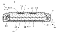
- FIG. 1 is a cross-sectional view showing the configuration of a coin-shaped secondary battery 1 according to the first embodiment of the present invention.
- the coin-type secondary battery 1 is, for example, a battery for soldering by a reflow method.
- the coin-type secondary battery 1 is mounted by being electrically connected to an object such as a wiring board by solder reflow. As a result, a battery-equipped device including the coin-type secondary battery 1 is manufactured.
- the vertical direction in FIG. 1 is also simply referred to as "vertical direction". The vertical direction does not have to coincide with the direction of gravity when the coin-type secondary battery 1 is actually used.
- the coin-type secondary battery 1 includes a positive electrode 2, a negative electrode 3, an electrolyte layer 4, an exterior body 5, a positive electrode current collector 62, a negative electrode current collector 63, and an elastic member 7.
- the electrolyte layer 4 is provided between the positive electrode 2 and the negative electrode 3.
- the exterior body 5 has a closed space inside.
- the positive electrode 2, the negative electrode 3, the electrolyte layer 4, the positive electrode current collector 62, the negative electrode current collector 63, and the elastic member 7 are housed in the enclosed space.
- the exterior body 5 includes a positive electrode can 51, a negative electrode can 52, and a gasket 53.
- the positive electrode can 51 includes a flat plate portion 511 and a peripheral wall portion 512.
- the flat plate portion 511 has a substantially disk shape.
- the peripheral wall portion 512 projects upward from the outer peripheral edge of the flat plate portion 511.
- the positive electrode can 51 is a container that houses the positive electrode 2.
- the negative electrode can 52 includes a flat plate portion 521 and a peripheral wall portion 522.
- the flat plate portion 521 has a substantially disk shape.
- the peripheral wall portion 522 projects downward from the outer peripheral edge of the flat plate portion 521.
- the negative electrode can 52 is a container that houses the negative electrode 3.
- the flat plate portion 511 of the positive electrode can 51, the positive electrode current collector 62, the positive electrode 2, the electrolyte layer 4, the negative electrode 3, the negative electrode current collector 63, the elastic member 7, and the flat plate portion 521 of the negative electrode can 52 are , Arrange in the vertical direction in this order from the lower side in FIG. As will be described later, the positive electrode current collector 62 and the negative electrode current collector 63 can be omitted.
- the negative electrode can 52 and the positive electrode can 51 are arranged so as to face the positive electrode 2 with the negative electrode 3 sandwiching the electrolyte layer 4.
- the gasket 53 is insulating and is provided between the peripheral wall portion 512 of the positive electrode can 51 and the peripheral wall portion 522 of the negative electrode can 52.
- the plate thickness of each of the positive electrode can 51 and the negative electrode can 52 is, for example, 0.075 to 0.25 mm.
- the elastic member 7 is a flexible and conductive plate member.
- the elastic member 7 illustrated in FIG. 1 is a thin metal leaf spring (also referred to as a disc spring).
- the outer shape of the elastic member 7 in a plan view is substantially circular. The details of the shape of the elastic member 7 will be described later.
- the elastic member 7 is made of, for example, stainless steel.
- the elastic member 7 may be formed of another metal (for example, aluminum) or a conductive material other than the metal (for example, a conductive resin). Further, in the elastic member 7, a through hole may be provided in the central portion in the radial direction as needed.
- the elastic member 7 is sandwiched between the flat plate portion 521 of the negative electrode can 52 and the negative electrode current collector 63. Further, the elastic member 7 and the negative electrode current collector 63 are arranged between the flat plate portion 521 of the negative electrode can 52 and the negative electrode 3.
- the elastic member 7 is elastically deformed by receiving a force from the flat plate portion 521 of the negative electrode can 52, the negative electrode current collector 63, and the negative electrode 3, and is compressed in the vertical direction.
- the elastic member 7 indirectly electrically connects the flat plate portion 521 of the negative electrode can 52 and the negative electrode 3 via the negative electrode current collector 63.
- the flat plate portion 521, the negative electrode 3, and the negative electrode current collector 63 are substantially parallel to each other.
- the negative electrode current collector 63 can be omitted.
- the elastic member 7 is arranged in a compressed state between the flat plate portion 521 of the negative electrode can 52 and the negative electrode 3, and is in direct contact with the negative electrode 3.
- the elastic member 7 directly electrically connects the flat plate portion 521 of the negative electrode can 52 and the negative electrode 3.
- the elastic member 7 indirectly or directly contacts the negative electrode 3, and directly or indirectly electrically connects the flat plate portion 521 of the negative electrode can 52 and the negative electrode 3. Since the force from the elastic member 7 also acts on the positive electrode 2 side, the positive electrode current collector 62 can also be omitted.
- the coin-type secondary battery 1 When the coin-type secondary battery 1 is fixed to an object such as a wiring board, for example, the coin-type secondary battery 1 is soldered to the object by a reflow method. At this time, since the coin-type secondary battery 1 is heated at a high temperature for a predetermined time, the pressure inside the exterior body 5 becomes high. In the coin-type secondary battery 1, by providing the elastic member 7, even if the exterior body 5 expands, the conductivity between the negative electrode 3 and the negative electrode can 52 and the distance between the positive electrode 2 and the positive electrode can 51 Conductivity is ensured.
- the positive electrode can 51 and the negative electrode can 52 shown in FIG. 1 are made of metal.
- the positive electrode can 51 and the negative electrode can 52 are formed by pressing (drawing) a metal plate such as stainless steel or aluminum. If a closed space is realized in the exterior body 5, even if the flat plate portions 511 and 521 and the peripheral wall portions 521 and 522 are formed by other methods in the positive electrode can 51 and the negative electrode can 52, respectively. good.
- the peripheral wall portion 512 of the positive electrode can 51 is arranged outside the peripheral wall portion 522 of the negative electrode can 52. Then, a downward load is applied to the flat plate portion 521 of the negative electrode can 52, and the peripheral wall portion 512 of the positive electrode can 51 is plastically deformed inward in the radial direction in a state where the elastic member 7 is compressed in the vertical direction. By crimping the peripheral wall portion 512 of the positive electrode can 51 in this way, the positive electrode can 51 is fixed to the negative electrode can 52 via the gasket 53. As a result, the enclosed space is formed.
- the area of the flat plate portion 511 of the positive electrode can 51 is larger than the area of the flat plate portion 521 of the negative electrode can 52. Further, the circumference of the peripheral wall portion 512 of the positive electrode can 51 is larger than the circumference of the peripheral wall portion 522 of the negative electrode can 52. Since the outer peripheral surface of the peripheral wall portion 522 of the negative electrode can 52 is covered with the gasket 53, the portion of the peripheral wall portion 522 of the negative electrode can 52 that comes into contact with the outside air is small.
- the gasket 53 is an annular member arranged between the peripheral wall portions 512 and 522. The gasket 53 is also filled between the peripheral wall portion 522 and the positive electrode 2 and the like.
- the gasket 53 is made of an insulating resin such as polypropylene, polytetrafluoroethylene, polyphenylene sulfide, perfluoroalkoxyalkane, or polychlorotrifluoroethylene. Of these, polyphenylene sulfide and perfluoroalkoxyalkane, which have excellent heat resistance, are preferable.
- the gasket 53 may be a member formed of another insulating material.
- the thickness of the coin-shaped secondary battery 1, that is, the distance between the outer surface of the flat plate portion 511 of the positive electrode can 51 and the outer surface of the flat plate portion 521 of the negative electrode can 52 is, for example, 0.7 mm or more and 1.6 mm or less. Is.
- the upper limit of the thickness of the coin-type secondary battery 1 is preferably 1.4 mm, more preferably 1. It is 2 mm.
- the lower limit of the thickness of the coin-type secondary battery 1 is preferably 0.8 mm, more preferably 0. It is 9.9 mm.
- the diameter of the coin-type secondary battery 1 is, for example, 10 mm or more and 20 mm or less.
- the diameter of the coin-shaped secondary battery 1 in FIG. 1 is the diameter of the flat plate portion 511 of the positive electrode can 51.
- the upper limit of the diameter of the coin-type secondary battery 1 is preferably 18 mm, more preferably 16 mm.
- the lower limit of the diameter of the coin-type secondary battery 1 is preferably 10.5 mm, more preferably 11 mm. ..
- a lithium composite oxide sintered body plate is used as the positive electrode 2
- a titanium-containing sintered body plate is used as the negative electrode 3.
- the positive electrode 2 is, for example, a sintered body plate (that is, a plate-shaped sintered body).
- the fact that the positive electrode 2 is a sintered body means that the positive electrode 2 does not contain a binder or a conductive auxiliary agent. This is because even if the green sheet contains a binder, the binder disappears or burns out during firing. Since the positive electrode 2 is a sintered body, heat resistance can be improved. Further, since the positive electrode 2 does not contain a binder, deterioration of the positive electrode 2 due to the electrolytic solution 42 (described later) is also suppressed.
- the positive electrode 2 is preferably porous, that is, contains pores.
- the preferred positive electrode 2 is a lithium composite oxide sintered body plate.
- the lithium composite oxide is particularly preferably lithium cobalt oxide (typically LiCoO 2 and hereinafter abbreviated as "LCO").
- the lithium composite oxide sintered body plate contains a plurality of primary particles composed of the lithium composite oxide, and the plurality of primary particles have an average orientation of more than 0 ° and 30 ° or less with respect to the plate surface of the positive electrode. It is preferably an oriented positive electrode plate that is oriented at an angle.
- the thickness of the positive electrode 2 is preferably 60 ⁇ m to 450 ⁇ m, more preferably 70 ⁇ m to 350 ⁇ m, and further preferably 90 ⁇ m to 300 ⁇ m. Within such a range, the active material capacity per unit area is increased to improve the energy density of the coin-type secondary battery 1, and the battery characteristics deteriorate (particularly, the resistance value increases) due to repeated charging and discharging. Can be suppressed.
- the negative electrode 3 is, for example, a sintered body plate (that is, a plate-shaped sintered body).
- the fact that the negative electrode 3 is a sintered body means that the negative electrode 3 does not contain a binder or a conductive auxiliary agent. This is because even if the green sheet contains a binder, the binder disappears or burns out during firing. Since the negative electrode 3 is a sintered body, heat resistance can be improved. Further, since the negative electrode 3 does not contain a binder and the packing density of the negative electrode active material (LTO or Nb 2 TiO 7 described later) is high, high capacity and good charge / discharge efficiency can be obtained.
- the negative electrode 3 is preferably porous, that is, contains pores.
- the preferred negative electrode 3 is a titanium-containing sintered plate.
- the titanium-containing sintered plate preferably contains lithium titanate Li 4 Ti 5 O 12 (hereinafter referred to as “LTO”) or niobium-titanium composite oxide Nb 2 TiO 7 , and more preferably contains LTO.
- LTO is typically known to have a spinel-type structure, other structures may be adopted during charging / discharging.
- LTO reacts in a two-phase coexistence of Li 4 Ti 5 O 12 (spinel structure) and Li 7 Ti 5 O 12 (rock salt structure) during charging and discharging. Therefore, LTO is not limited to the spinel structure.
- the titanium-containing sintered plate has a structure in which a plurality of (that is, a large number of) primary particles are bonded. Therefore, it is preferable that these primary particles are composed of LTO or Nb 2 TiO 7.
- the thickness of the negative electrode 3 is preferably 70 ⁇ m to 500 ⁇ m, preferably 85 ⁇ m to 400 ⁇ m, and more preferably 95 ⁇ m to 350 ⁇ m.
- the thickness of the negative electrode 3 can be obtained, for example, by measuring the distance between the plate surfaces observed substantially in parallel when the cross section of the negative electrode 3 is observed by an SEM (scanning electron microscope).
- the electrolyte layer 4 includes a separator 41 and an electrolytic solution 42.
- the separator 41 is provided between the positive electrode 2 and the negative electrode 3.
- the separator 41 is porous, and the electrolytic solution 42 is mainly impregnated in the separator 41.
- the electrolytic solution 42 is also impregnated with the positive electrode 2 and the negative electrode 3.
- the electrolytic solution 42 may be present in the gap between the positive electrode 2, the negative electrode 3, the separator 41 and the like and the exterior body 5.
- the separator 41 is preferably a cellulosic or ceramic separator.
- Cellulose separators are advantageous in that they are inexpensive and have excellent heat resistance.
- the cellulose separator is different from the widely used polyolefin separator having poor heat resistance, and is not only excellent in heat resistance itself, but also ⁇ -butyrolactone (GBL) which is an electrolytic solution component having excellent heat resistance. ) Is also excellent in wettability. Therefore, when an electrolytic solution containing GBL is used, the electrolytic solution can be sufficiently permeated into the separator (without repelling).
- the ceramic separator has an advantage that it can be manufactured as one integrally sintered body together with the positive electrode 2 and the negative electrode 3 as a whole, as well as being excellent in heat resistance.
- the ceramic constituting the separator is preferably at least one selected from MgO, Al 2 O 3 , ZrO 2 , SiC, Si 3 N 4 , Al N and cordierite, and more preferably MgO. , Al 2 O 3 and ZrO 2 are at least one selected.
- the electrolytic solution 42 is not particularly limited, and when the coin-type secondary battery 1 is a lithium secondary battery, a commercially available electrolytic solution for a lithium battery, such as a solution in which a lithium salt is dissolved in a non-aqueous solvent such as an organic solvent, is used.
- a liquid may be used.
- an electrolytic solution having excellent heat resistance is preferable, and such an electrolytic solution preferably contains lithium borofluoride (LiBF 4) in a non-aqueous solvent.
- the preferred non-aqueous solvent is at least one selected from the group consisting of ⁇ -butyrolactone (GBL), ethylene carbonate (EC) and propylene carbonate (PC), and more preferably a mixed solvent consisting of EC and GBL.
- GBL ⁇ -butyrolactone
- EC ethylene carbonate
- PC propylene carbonate
- the volume ratio of EC: GBL in the EC and / or GBL-containing non-aqueous solvent is preferably 0: 1 to 1: 1 (GBL ratio: 50% by volume to 100% by volume), more preferably 0: 1 to 1: 1.5 (GBL ratio 60% by volume to 100% by volume), more preferably 0: 1 to 1: 2 (GBL ratio 66.6% by volume to 100% by volume), particularly preferably 0: 1 to 100% by volume. It is 1: 3 (GBL ratio 75% by volume to 100% by volume).
- Lithium borofluoride (LiBF 4 ) dissolved in a non-aqueous solvent is an electrolyte having a high decomposition temperature, which also brings about a significant improvement in heat resistance.
- the concentration of LiBF 4 in the electrolytic solution 42 is preferably 0.5 mol / L to 2 mol / L, more preferably 0.6 mol / L to 1.9 mol / L, and further preferably 0.7 mol / L to 1.7 mol. / L, particularly preferably 0.8 mol / L to 1.5 mol / L.
- the electrolytic solution 42 may further contain vinylene carbonate (VC) and / or fluoroethylene carbonate (FEC) and / or vinylethylene carbonate (VEC) as additives. Both VC and FEC have excellent heat resistance. Therefore, when the electrolytic solution 42 contains such an additive, an SEI film having excellent heat resistance can be formed on the surface of the negative electrode 3.
- VC vinylene carbonate
- FEC fluoroethylene carbonate
- VEC vinylethylene carbonate
- the material and shape thereof are not particularly limited, but the current collector is preferably a metal such as copper foil or aluminum foil. It is a foil. Further, it is preferable that the positive electrode side carbon layer 621 is provided between the positive electrode 2 and the positive electrode current collector 62 from the viewpoint of reducing contact resistance. Similarly, it is preferable that the negative electrode side carbon layer 631 is provided between the negative electrode 3 and the negative electrode current collector 63 from the viewpoint of reducing contact resistance. Both the positive electrode side carbon layer 621 and the negative electrode side carbon layer 631 are preferably composed of conductive carbon, and may be formed by, for example, applying a conductive carbon paste by screen printing or the like. As another method, metal or carbon may be formed on the electrode current collecting surface by sputtering. Examples of metal species include Au, Pt, Al and the like.
- FIG. 2 is a plan view showing the elastic member 7.
- FIG. 3 is a cross-sectional view of the elastic member 7 cut at the positions III-III in FIG. 2 and 3 show a free state in which the elastic member 7 is neither compressed nor stretched (the same applies to FIGS. 6 to 9, 11 to 12, 14 to 15, 17 to 18, 20 to 21).
- the outer shape of the elastic member 7 in a plan view is a substantially circular shape centered on the center C.
- first radial direction the direction parallel to the diameter extending in the left-right direction in FIG. 2 through the center C
- second radial direction the direction parallel to the diameter extending in the vertical direction in FIG. 2 through the center C.
- the second radial direction is orthogonal to the first radial direction.
- the elastic member 7 includes a plurality of convex portions 71 and 72 that are convex in the vertical direction.
- the plurality of convex portions 71 and 72 can be elastically deformed in the vertical direction.
- the height of the elastic member 7 in the vertical direction is emphasized more than it actually is (the same applies to FIGS. 7, 9, 12, 15, 18, and 20).
- the diameter of the elastic member 7 in a plan view is, for example, 9.900 mm or more and 19.850 mm or less, preferably 9.900 mm or more and 17.815 mm or less, and more preferably 9.900 mm or more and 17.600 mm or less. be.
- the thickness of the metal plate forming the elastic member 7 (hereinafter, also simply referred to as “the thickness of the elastic member 7”) is, for example, 0.027 mm or more and 0.103 mm or less, preferably 0.047 mm or more and 0. It is 0.083 mm or less, more preferably 0.047 mm or more and 0.053 mm or less. In the examples shown in FIGS. 2 and 3, the plate thickness of the elastic member 7 is substantially the same over the entire surface of the elastic member 7.
- the free height of the elastic member 7 (that is, the height in the vertical direction in a free state in which it is neither compressed nor stretched) is, for example, 0.054 mm or more and 0.900 mm or less, preferably 0.190 mm or more and 0. It is 620 mm or less, more preferably 0.190 mm or more and 0.290 mm or less.
- the surface roughness of the elastic member 7 is, for example, 1.0 ⁇ m or more and 30.0 ⁇ m or less, preferably 3.0 ⁇ m or more and 10.0 ⁇ m or less.
- the surface roughness is the center line average roughness (Ra), and the same applies to the following description. In the examples shown in FIGS. 2 and 3, the surface roughness of the elastic member 7 is substantially the same over the entire surface of the elastic member 7.
- the convex portions 71 and 72 of the elastic member 7 are also referred to as “first convex portion 71" and “second convex portion 72", respectively.
- the elastic member 7 includes two first convex portions 71 and one second convex portion 72 that are convex upward.
- the two first convex portions 71 and the one second convex portion 72 are alternately arranged in a predetermined arrangement direction substantially parallel to the first radial direction.
- two first convex portions 71 are arranged adjacent to each other on both sides of the second convex portion 72.
- the two first convex portions 71 are located at both ends in the arrangement direction, and the second convex portions 72 are located on the center C of the elastic member 7 between the two first convex portions 71.
- each of the first convex portion 71 and the second convex portion 72 extends substantially linearly in the second radial direction (that is, a direction substantially perpendicular to the arrangement direction).
- the elastic member 7 is a corrugated plate in which three linear convex portions 71 and 72 are arranged in an arrangement direction substantially perpendicular to the longitudinal direction of the convex portions 71 and 72.
- each of the first convex portion 71 and the second convex portion 72 is a so-called “mountain portion”
- the portion between each first convex portion 71 and the second convex portion 72 is a so-called "valley portion".
- the first convex portion 71 extends in the longitudinal direction from a part of the peripheral edge of the substantially disk-shaped elastic member 7, and is located at a position opposed to the part of the peripheral edge of the elastic member 7 in the longitudinal direction. It reaches the department. The same applies to the second convex portion 72.
- the number of the first convex portions 71 may be 1 or 3 or more, and the number of the second convex portions 72 may be 2 or more. Further, in the elastic member 7, three or more convex portions 71 and 72 may be arranged in the above-mentioned arrangement direction. In this case, the first convex portion 71 and the second convex portion 72 do not necessarily have to be arranged alternately, and the first convex portions 71 and / or the second convex portions 72 are adjacent to each other in the arrangement direction. May be good.
- the widths of the first convex portion 71 and the second convex portion 72 in the arrangement direction are substantially the same.
- the arrangement direction is also referred to as "width direction”.
- the vertical heights (that is, free heights) of the first convex portion 71 and the second convex portion 72 in the free state are substantially the same.
- the plate thickness and surface roughness of each of the first convex portion 71 and the second convex portion 72 are substantially the same.
- each first convex portion 71 is a flat portion 711 substantially perpendicular to the vertical direction.
- the flat surface portion 711 is provided over substantially the entire length of the first convex portion 71 in the longitudinal direction (that is, the second radial direction).
- the width of the flat surface portion 711 in the first radial direction is substantially constant over the substantially overall length in the longitudinal direction.
- the top portion (that is, the upper end portion) of the second convex portion 72 is a flat surface portion 721 that is substantially perpendicular to the vertical direction.
- the flat surface portion 721 is provided over substantially the entire length of the first convex portion 72 in the longitudinal direction (that is, the second radial direction).
- the width of the flat surface portion 721 in the first radial direction is substantially constant over the substantially overall length in the longitudinal direction.
- the flat surface portion 711 of the two first convex portions 71 of the elastic member 7 and the first convex portion 71 before the negative electrode can 52 is arranged on the positive electrode can 51.
- the flat surface portion 721 of the two convex portions 72 at least one flat surface portion (for example, the flat surface portion 721 of the second convex portion 72) is welded and fixed to the flat plate portion 521 of the negative electrode can 52.
- the negative electrode can 52 and the elastic member 7 can be handled together, so that the production of the coin-type secondary battery 1 can be simplified.
- the flat surface portion that is not welded to the flat plate portion 521 of the negative electrode can 52 may be omitted.
- each first convex portion 71 that is, the curvature at the top assuming that the flat portion 711 is not provided
- the curvature of the upper end of the second convex portion 72 that is, the flat portion 721 is provided. Curvature at the top, assuming that it is not possible
- Curvature at the top assuming that it is not possible
- the curvature of the upper end of the first convex portion 71 and the second convex portion 72 is simply referred to as “curvature”.
- FIG. 4 is an enlarged view showing a portion of the coin-shaped secondary battery 1 in the vicinity of the elastic member 7.
- the height of the elastic member 7 in the vertical direction is emphasized more than it actually is (the same applies to FIGS. 5, 10, 13, 16 and 19).
- the flat plate portion 521 of the negative electrode can 52 is formed of a relatively thin member that is easily elastically deformed, and the radial central portion of the flat plate portion 521 projects upward with respect to the peripheral edge portion. In other words, the flat plate portion 521 is deformed so that the central portion in the radial direction becomes convex toward the upper side.
- the height of the radial center portion of the elastic member space 70 in the vertical direction is high.
- the height is higher than the height of the peripheral edge of the elastic member space 70 in the vertical direction.
- the deformation of the flat plate portion 521 in the vertical direction is emphasized more than the actual deformation.
- the elastic member 7 is elastically deformed by being compressed in the vertical direction between the flat plate portion 521 and the negative electrode 3 of the negative electrode can 52, and the first convex portion 71 and the second convex portion 72 of each.
- the top portion is in contact with the flat plate portion 521 of the negative electrode can 52.
- the top of the second convex portion 72 located at the central portion in the width direction is located above the top of each first convex portion 71 located at the end portion in the width direction.
- the amount of vertical displacement of the second convex portion 72 of the elastic member 7 (that is, the amount of vertical displacement due to compression between the negative electrode 3 and the flat plate portion 521) is smaller than the amount of vertical displacement of the first convex portion 71. .. Therefore, the difference between the compressive stress acting on the second convex portion 72 and the yield stress of the second convex portion 72 is the compressive stress acting on each first convex portion 71 and the yield of the first convex portion 71. Greater than the difference with stress. In the following description, the difference between the compressive stress and the yield stress acting on the convex portions 71 and 72 is also referred to as a “yield margin”.
- the yield margin of the second convex portion 72 is larger than the yield margin of each of the first convex portions 71.
- the timing of yielding can be staggered between the first convex portion 71 and the second convex portion 72.
- the yield margins of the first convex portion 71 and the second convex portion 72 are substantially the same, and the negative electrode can 52 is compared with the case where the first convex portion 71 and the second convex portion 72 yield substantially at the same time.
- the electrical connection between the flat plate portion 521 and the negative electrode 3 can be maintained for a long period of time, and the life of the coin-type secondary battery 1 can be extended.
- the elastic member 7 does not necessarily have to be arranged between the negative electrode 3 and the flat plate portion 521 of the negative electrode can 52, and the flat plate portion 511 of the positive electrode can 51, the positive electrode current collector 62, and the positive electrode can It may be arranged between the positive electrode 2 and the positive electrode 2.
- the elastic member 7 is elastically deformed by receiving a force from the flat plate portion 511 of the positive electrode can 51, the positive electrode current collector 62, and the positive electrode 2, and is compressed in the vertical direction.
- the elastic member 7 indirectly electrically connects the flat plate portion 511 of the positive electrode can 51 and the positive electrode 2 via the positive electrode current collector 62.
- the elastic member 7 directly electrically connects the flat plate portion 511 of the positive electrode can 51 and the positive electrode 2.
- the flat plate portion 511 of the positive electrode can 51 is deformed in substantially the same manner as the flat plate portion 521 of the negative electrode can 52 shown in FIG. 4, and the shape of the elastic member 7 is also substantially the same as that shown in FIG. Is.
- the coin-type secondary battery 1 includes a positive electrode 2, a negative electrode 3, an electrolyte layer 4, an exterior body 5, and a conductive elastic member 7.
- the positive electrode 2 and the negative electrode 3 are arranged in the vertical direction.
- the electrolyte layer 4 is provided between the positive electrode 2 and the negative electrode 3.
- the exterior body 5 has a closed space for accommodating the positive electrode 2, the negative electrode 3, and the electrolyte layer 4.
- the elastic member 7 is arranged in a vertically compressed state between one of the electrodes of the positive electrode 2 and the negative electrode 3 and the flat plate portion (that is, the flat plate portion 511 or the flat plate portion 521) of the exterior body 5. ..
- the elastic member 7 electrically connects the one electrode and the flat plate portion indirectly or directly.
- the elastic member 7 includes a plurality of convex portions that are convex in the vertical direction.
- the plurality of convex portions include a first convex portion 71 and a second convex portion 72 having a yield margin different from that of the first convex portion 71, which is the difference between the compressive stress and the yield stress acting in the vertical direction. ..
- the timing at which the first convex portion 71 yields and the timing at which the second convex portion 72 yields can be shifted.
- the yield margin of the second convex portion 72 is larger than the yield margin of the first convex portion 71. Therefore, the first convex portion 71 yields first, and the second convex portion 72 remains in an elastically deformed state for a certain period of time.
- the yield margins of the first convex portion 71 and the second convex portion 72 are substantially the same, and the flat plate portion of the negative electrode can 52 is compared with the case where the first convex portion 71 and the second convex portion 72 yield substantially at the same time.
- the electrical connection between the 521 and the negative electrode 3 and the electrical connection between the flat plate portion 511 of the positive electrode can 51 and the positive electrode 2 can be maintained for a long period of time. Specifically, when the coin-type secondary battery 1 is exposed to changes in the operating temperature environment (including those due to the charge / discharge state), the first convex portion 71 that yields quickly is the coin-type secondary battery 1.
- the amount of vertical displacement which is the amount of vertical displacement due to compression between one of the electrodes and the flat plate portion, is the amount of vertical displacement of the second convex portion 72 and the amount of vertical displacement. 1
- the amount of vertical displacement of the convex portion 71 is different.
- the yield margin of the second convex portion 72 and the yield margin of the first convex portion 71 can be easily made different.
- the amount of vertical displacement of the second convex portion 72 is smaller than the amount of vertical displacement of the first convex portion 71. Therefore, the yield margin of the second convex portion 72 can be easily made larger than the yield margin of the first convex portion 71. As a result, the life of the coin-type secondary battery 1 can be extended without excessively complicating the structure of the coin-type secondary battery 1.
- the plurality of convex portions are three or more convex portions arranged in a predetermined arrangement direction parallel to one radial direction (in the above example, the first radial direction), and the first Of the convex portion 71 and the second convex portion 72, the convex portion having the larger yield margin (in the above example, the second convex portion 72) is a convex portion located at both ends in the arrangement direction among the plurality of convex portions. It is a convex part other than. As a result, the area of the convex portion can be increased as compared with the case where the convex portion having the larger yield margin is located at the end portion in the arrangement direction.
- the convex portion having a smaller yield margin (the first convex portion 71 in the above example) yields due to a change with time of the coin-shaped secondary battery 1, the flat plate portion and the elastic member 7 remain in contact with each other.
- the contact area can be maintained relatively large.
- the long-term reliability of the electrical connection in the coin-type secondary battery 1 that is, the electrical connection between the negative electrode 3 and the flat plate portion 521 and the electrical connection between the positive electrode 2 and the flat plate portion 511) is improved. can do.
- the plurality of convex portions (that is, the first convex portion 71 and the second convex portion 72) are predetermined to be parallel to one radial direction (in the above example, the first radial direction).
- each of the plurality of convex portions extends linearly in a direction perpendicular to the arrangement direction.
- the shape of the elastic member 7 can be simplified.
- the coin-type secondary battery 1 can be easily manufactured. The same applies to the coin-type secondary battery 1 including the elastic members 7a to 7e described later.
- the top of at least one of the plurality of convex portions is a flat portion (that is, a flat portion perpendicular to the vertical direction). It is a flat surface portion 711 or a flat surface portion 721), and is welded to the above-mentioned flat plate portion (that is, the flat plate portion 511 or the flat plate portion 521 of the exterior body 5).
- the elastic member 7 the area of the welded portion with the exterior body 5 can be increased, and the stress concentration at the welded portion can be suppressed. Further, the elastic member 7 and the exterior body 5 can be joined while suppressing a decrease in strength of the elastic member 7 due to spatter or the like. The same applies to the coin-type secondary battery 1 including the elastic members 7a to 7d described later.
- the heights of the plurality of convex portions that is, the first convex portion 71 and the second convex portion 72
- the shape of the elastic member 7 can be simplified.
- the coin-type secondary battery 1 can be easily manufactured.
- the coin-type secondary battery 1 provided with elastic members 7b to 7e which will be described later.
- FIG. 5 is an enlarged cross-sectional view showing a portion of the coin-shaped secondary battery 1a in the vicinity of the elastic member 7a.
- an elastic member 7a having a structure different from that of the elastic member 7 is provided instead of the elastic member 7 shown in FIGS. 2 and 3.
- the flat plate portion 521a of the negative electrode can 52 is formed of a relatively thick member that is not easily elastically deformed, and the flat plate portion 521a spreads substantially vertically in the vertical direction. Therefore, the height of the elastic member space 70a is substantially constant throughout.
- Other configurations of the coin-type secondary battery 1a are the same as those of the coin-type secondary battery 1, and in the following description, the corresponding configurations are designated by the same reference numerals.
- the elastic member 7a is a thin leaf spring having a substantially circular shape in a plan view.
- the elastic member 7a includes two first convex portions 71a and one second convex portion 72a.
- the two first convex portions 71a are located at both ends in the arrangement direction (that is, the first radial direction described above), similarly to the first convex portion 71 described above.
- the second convex portion 72a is located on the center C of the elastic member 7a between the two first convex portions 71a, similarly to the second convex portion 72 described above.
- Each of the first convex portion 71a and the second convex portion 72a extends substantially linearly in the above-mentioned second radial direction (that is, a direction substantially perpendicular to the arrangement direction).
- the widths of the first convex portion 71a and the second convex portion 72a in the arrangement direction are substantially the same.
- the plate thickness and surface roughness of each of the first convex portion 71a and the second convex portion 72a are substantially the same.
- the free heights of the first convex portion 71a and the second convex portion 72a are different.
- the free height of each first convex portion 71a is higher than the free height of the second convex portion 72a. Therefore, as shown in FIG. 5, when the height of the elastic member space 70a is constant as a whole, the vertical displacement of each first convex portion 71a in the elastic member 7a housed in the elastic member space 70a. The amount is larger than the amount of vertical displacement of the second convex portion 72a. Therefore, the yield margin of the second convex portion 72a (that is, the difference between the compressive stress acting in the vertical direction and the yield stress) is larger than the yield margin of the first convex portion 71a.
- the elastic member 7a does not necessarily have to be arranged between the negative electrode 3 and the flat plate portion 521a of the negative electrode can 52, and the flat plate portion 511 of the positive electrode can 51 and the positive electrode 2 (see FIG. 1). It may be placed between and. In this case, the elastic member 7a indirectly or directly electrically connects the flat plate portion 511 of the positive electrode can 51 and the positive electrode 2 in a state of being compressed in the vertical direction. Since the flat plate portion 511 of the positive electrode can 51 is substantially perpendicular to the flat plate portion 521a of the negative electrode can 52 shown in FIG. 5 in the vertical direction, the shape of the elastic member 7a is also substantially the same as that shown in FIG. ..
- the elastic member 7a includes a plurality of convex portions that are convex in the vertical direction, and the plurality of convex portions are formed.
- a first convex portion 71a and a second convex portion 72a having a yield margin different from that of the first convex portion 71a are provided.
- the first convex portion 71a yields first, and the second convex portion 72a remains in an elastically deformed state for a certain period of time.
- the yield margins of the first convex portion 71a and the second convex portion 72a are substantially the same, and the flat plate portion of the negative electrode can 52 is compared with the case where the first convex portion 71a and the second convex portion 72a yield substantially at the same time.
- the electrical connection between the 521a and the negative electrode 3 and the electrical connection between the flat plate portion 511 of the positive electrode can 51 and the positive electrode 2 (see FIG. 1) can be maintained for a long period of time. Therefore, the life of the coin-type secondary battery 1a can be extended.
- the vertical displacement amount of the second convex portion 72a and the vertical displacement amount of the first convex portion 71a are different.
- the yield margin of the second convex portion 72a and the yield margin of the first convex portion 71a can be easily made different.
- the amount of vertical displacement of the second convex portion 72a is smaller than the amount of vertical displacement of the first convex portion 71a. Therefore, the yield margin of the second convex portion 72a can be easily made larger than the yield margin of the first convex portion 71a.
- the life of the coin-type secondary battery 1a can be extended without excessively complicating the structure of the coin-type secondary battery 1a.
- the elastic member 7a may be arranged in the elastic member space 70 having a high radial center portion in the coin-shaped secondary battery 1 (see FIG. 1). Also in this case, the amount of vertical displacement of the second convex portion 72a is smaller than the amount of vertical displacement of the first convex portion 71a. Therefore, since the yield margin of the second convex portion 72a is larger than the yield margin of the first convex portion 71a, the first convex portion 71a yields first, and the second convex portion 72a remains in an elastically deformed state for a certain period of time. do.
- the free height of the second convex portion 72a may be higher than the free height of each first convex portion 71a.
- the vertical displacement amount of the second convex portion 72a is the vertical displacement amount of each first convex portion 71a. Greater than. Therefore, since the yield margin of the second convex portion 72a is smaller than the yield margin of the first convex portion 71a, the second convex portion 72a yields first, and the first convex portion 71a remains in an elastically deformed state for a certain period of time. do.
- the elastic member 7a may be arranged in the elastic member space 70 (see FIG. 1) of the coin-shaped secondary battery 1.
- the coin-shaped secondary battery 1, 1a described above may be provided with an elastic member having a structure different from that of the elastic members 7, 7a.
- elastic members 7b to 7e having a structure different from that of the elastic members 7 and 7a will be described.
- the elastic member 7b is a thin leaf spring having a substantially circular shape in a plan view.
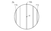
- the elastic member 7b includes two first convex portions 71b and one second convex portion 72b.
- the two first convex portions 71b are located at both ends in the arrangement direction (that is, the first radial direction described above), similarly to the first convex portion 71 described above.
- the second convex portion 72b is located on the center C of the elastic member 7b between the two first convex portions 71b, similarly to the second convex portion 72 described above.
- Each of the first convex portion 71b and the second convex portion 72b extends substantially linearly in the above-mentioned second radial direction (that is, a direction substantially perpendicular to the arrangement direction).
- the free heights of the first convex portion 71b and the second convex portion 72b are substantially the same.
- the plate thickness and surface roughness of each of the first convex portion 71b and the second convex portion 72b are substantially the same.
- the widths of the first convex portion 71b and the second convex portion 72b in the arrangement direction are different, so that the spring constant of the first convex portion 71b in the vertical direction is the first. It is different from the spring constant of the two convex portions 72b.
- the width of the second convex portion 72b is larger than the width of each first convex portion 71b, so that the spring constant of the second convex portion 72b is the spring constant of the first convex portion 71b. Smaller than
- the vertical displacement amount of each first convex portion 71b becomes the first. It is substantially the same as the amount of vertical displacement of the two convex portions 72b. Therefore, the compressive stress acting in the vertical direction on the first convex portion 71b having a large spring constant is larger than the compressive stress acting in the vertical direction on the second convex portion 72b having a small spring constant. Therefore, the yield margin of the second convex portion 72b is larger than the yield margin of the first convex portion 71b.
- the plurality of convex portions of the elastic member 7b include the first convex portion 71b and the second convex portion 72b having a yield margin different from that of the first convex portion 71b.
- the timing at which the first convex portion 71b yields and the timing at which the second convex portion 72b yields can be shifted.
- the spring constant of the second convex portion 72b and the spring constant of the first convex portion 71b are different from each other, so that the second convex portion 72b yields.
- the margin and the yield margin of the first convex portion 71b can be easily made different. As a result, the life of the coin-type secondary battery 1a can be extended without excessively complicating the structure of the coin-type secondary battery 1a.
- the difference in the spring constants of the first convex portion 71b and the second convex portion 72b is due to the difference in the widths of the first convex portion 71b and the second convex portion 72b.
- the spring constant of the first convex portion 71b and the spring constant of the second convex portion 72b can be easily made different.
- the elastic member 7b may be arranged in the elastic member space 70 having a high radial center portion in the coin-shaped secondary battery 1 (see FIG. 1).
- the spring constant and the amount of vertical displacement of the second convex portion 72b are smaller than the spring constant and the amount of vertical displacement of the first convex portion 71b. Therefore, the compressive stress acting on the second convex portion 72b in the vertical direction is smaller than the compressive stress acting on the first convex portion 71b in the vertical direction.
- the yield margin of the second convex portion 72b is larger than the yield margin of the first convex portion 71b, the first convex portion 71b yields first, and the second convex portion 72b remains in an elastically deformed state for a certain period of time. do.
- the width of the second convex portion 72b may be smaller than the width of each first convex portion 71b.
- the spring constant of the second convex portion 72b becomes larger than the spring constant of the first convex portion 71b. Therefore, in the elastic member 7b housed in the elastic member space 70a (see FIG. 10) of the coin-shaped secondary battery 1a, the vertical compressive stress acting on the second convex portion 72b acts on the first convex portion 71b. It is larger than the compressive stress in the vertical direction.
- the elastic member 7b may be arranged in the elastic member space 70 (see FIG. 1) of the coin-shaped secondary battery 1.
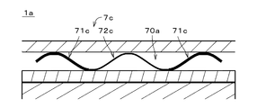
- the elastic member 7c is a thin leaf spring having a substantially circular shape in a plan view.
- the elastic member 7c includes two first convex portions 71c and one second convex portion 72c.
- the two first convex portions 71c are located at both ends in the arrangement direction (that is, the first radial direction described above), similarly to the first convex portion 71 described above.
- the second convex portion 72c is located on the center C of the elastic member 7c between the two first convex portions 71c, similarly to the second convex portion 72 described above.
- Each of the first convex portion 71c and the second convex portion 72c extends substantially linearly in the above-mentioned second radial direction (that is, a direction substantially perpendicular to the arrangement direction).
- the free heights of the first convex portion 71c and the second convex portion 72c are substantially the same.
- the widths of the first convex portion 71c and the second convex portion 72c in the arrangement direction are substantially the same.
- the surface roughness of each of the first convex portion 71c and the second convex portion 72c is substantially the same.
- the spring constant of the first convex portion 71c is different from the spring constant of the second convex portion 72c.
- the spring constant of the second convex portion 72c is larger than the spring constant of the first convex portion 71c. Is also small.
- the plurality of convex portions of the elastic member 7c include the first convex portion 71c and the second convex portion 72c having a yield margin different from that of the first convex portion 71c.
- the timing at which the first convex portion 71c yields and the timing at which the second convex portion 72c yields can be shifted.
- the spring constant of the second convex portion 72c and the spring constant of the first convex portion 71c are different from each other, so that the second convex portion 72c yields.
- the margin and the yield margin of the first convex portion 71c can be easily made different. As a result, the life of the coin-type secondary battery 1a can be extended without excessively complicating the structure of the coin-type secondary battery 1a.
- the difference in the spring constants between the first convex portion 71c and the second convex portion 72c is due to the difference in the plate thickness between the first convex portion 71c and the second convex portion 72c.
- the spring constant of the first convex portion 71c and the spring constant of the second convex portion 72c can be easily made different.
- the elastic member 7c may be arranged in the elastic member space 70 having a high radial center portion in the coin-shaped secondary battery 1 (see FIG. 1).
- the spring constant and the amount of vertical displacement of the second convex portion 72c are smaller than the spring constant and the amount of vertical displacement of the first convex portion 71c. Therefore, the compressive stress acting on the second convex portion 72c in the vertical direction is smaller than the compressive stress acting on the first convex portion 71c in the vertical direction.
- the yield margin of the second convex portion 72c is larger than the yield margin of the first convex portion 71c, the first convex portion 71c yields first, and the second convex portion 72c remains in an elastically deformed state for a certain period of time. do.
- the plate thickness of the second convex portion 72c may be larger than the plate thickness of each first convex portion 71c.
- the spring constant of the second convex portion 72c becomes larger than the spring constant of the first convex portion 71c. Therefore, in the elastic member 7c housed in the elastic member space 70a (see FIG. 13) of the coin-shaped secondary battery 1a, the vertical compressive stress acting on the second convex portion 72c acts on the first convex portion 71c. It is larger than the compressive stress in the vertical direction.
- the elastic member 7c may be arranged in the elastic member space 70 (see FIG. 1) of the coin-shaped secondary battery 1.
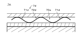
- the elastic member 7d is a thin leaf spring having a substantially circular shape in a plan view.
- the elastic member 7d includes two first convex portions 71d and one second convex portion 72d.
- the two first convex portions 71d are located at both ends in the arrangement direction (that is, the first radial direction described above), similarly to the first convex portion 71 described above.
- the second convex portion 72d is located on the center C of the elastic member 7d between the two first convex portions 71d, similarly to the second convex portion 72 described above.
- Each of the first convex portion 71d and the second convex portion 72d extends substantially linearly in the above-mentioned second radial direction (that is, a direction substantially perpendicular to the arrangement direction).
- the free heights of the first convex portion 71d and the second convex portion 72d are substantially the same.
- the widths of the first convex portion 71d and the second convex portion 72d in the arrangement direction are substantially the same.
- the plate thicknesses of the first convex portion 71d and the second convex portion 72d are also substantially the same.
- the surface roughness of the first convex portion 71d and the second convex portion 72d is different. Therefore, when the coin-type secondary battery 1a is mounted on an object by solder reflow, or when it is exposed to a temperature change environment and thermal expansion occurs repeatedly, the exterior body 5 (see FIG. 1) to the first.
- the amount of heat conducted to the convex portion 71d and the amount of heat conducted from the exterior body 5 to the second convex portion 72d are different. Therefore, the degree of decrease in Young's modulus due to the heat conducted from the exterior body 5 (that is, the heat input from the exterior body 5) differs between the first convex portion 71d and the second convex portion 72d.
- the surface roughness of the first convex portion 71d is larger than the surface roughness of the second convex portion 72d. Therefore, the amount of heat input to the second convex portion 72d is larger than the amount of heat input to the first convex portion 71d, and the Young's modulus of the second convex portion 72d is significantly lower than the Young's modulus of the first convex portion 71d. Therefore, the Young's modulus of the second convex portion 72d is smaller than the Young's modulus of the first convex portion 71d. As a result, the spring constant of the second convex portion 72d becomes smaller than the spring constant of the first convex portion 71d.
- a parallel diagonal line is provided on the first convex portion 71d having a large surface roughness, and in FIG. 15, the surface (that is, the upper surface) of the first convex portion 71d is drawn by a broken line.
- the vertical displacement amount of each first convex portion 71d becomes the first. It is substantially the same as the amount of vertical displacement of the two convex portions 72d. Therefore, the compressive stress acting in the vertical direction on the first convex portion 71d having a large Young's modulus is larger than the compressive stress acting in the vertical direction on the second convex portion 72d having a small Young's modulus. Therefore, the yield margin of the second convex portion 72d is larger than the yield margin of the first convex portion 71d.
- the plurality of convex portions of the elastic member 7d include the first convex portion 71d and the second convex portion 72d having a yield margin different from that of the first convex portion 71d.
- the timing at which the first convex portion 71d yields and the timing at which the second convex portion 72d yields can be shifted.
- the yield of the second convex portion 72d is different due to the difference between the Young's modulus of the second convex portion 72d and the Young's modulus of the first convex portion 71d.
- the margin and the yield margin of the first convex portion 71d can be easily made different. As a result, the life of the coin-type secondary battery 1a can be extended without excessively complicating the structure of the coin-type secondary battery 1a.
- the difference in spring constant between the first convex portion 71d and the second convex portion 72d is due to the difference in Young's modulus between the first convex portion 71d and the second convex portion 72d, and the first convex portion 72d.
- the difference in Young's modulus between the portion 71d and the second convex portion 72d is due to the difference in surface roughness between the first convex portion 71d and the second convex portion 72d.
- the elastic member 7d may be arranged in the elastic member space 70 having a high radial center portion in the coin-shaped secondary battery 1 (see FIG. 1).
- the spring constant and the amount of vertical displacement of the second convex portion 72d are smaller than the spring constant and the amount of vertical displacement of the first convex portion 71d. Therefore, the compressive stress acting on the second convex portion 72d in the vertical direction is smaller than the compressive stress acting on the first convex portion 71d in the vertical direction.
- the yield margin of the second convex portion 72d is larger than the yield margin of the first convex portion 71d, the first convex portion 71d yields first, and the second convex portion 72d remains in an elastically deformed state for a certain period of time. do.
- the surface roughness of the second convex portion 72d may be larger than the surface roughness of each first convex portion 71d.
- the Young's modulus of the second convex portion 72d is larger than the Young's modulus of the first convex portion 71d.
- the spring constant of the second convex portion 72d becomes larger than the spring constant of the first convex portion 71d. Therefore, in the elastic member 7d housed in the elastic member space 70a (see FIG. 16) of the coin-shaped secondary battery 1a, the vertical compressive stress acting on the second convex portion 72d acts on the first convex portion 71d. It is larger than the compressive stress in the vertical direction.
- the elastic member 7d may be arranged in the elastic member space 70 (see FIG. 1) of the coin-shaped secondary battery 1.
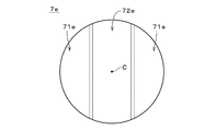
- the 17 and 18 are a plan view and a cross-sectional view showing the elastic member 7e, respectively.
- the elastic member 7e is a thin leaf spring having a substantially circular shape in a plan view.
- the elastic member 7e includes two first convex portions 71e and one second convex portion 72e.
- the two first convex portions 71e are located at both ends in the arrangement direction (that is, the above-mentioned first radial direction), similarly to the first convex portion 71 described above.
- the second convex portion 72e is located on the center C of the elastic member 7e between the two first convex portions 71e, similarly to the second convex portion 72 described above.
- Each of the first convex portion 71e and the second convex portion 72e extends substantially linearly in the above-mentioned second radial direction (that is, a direction substantially perpendicular to the arrangement direction).
- the free heights of the first convex portion 71e and the second convex portion 72e are substantially the same.
- the widths of the first convex portion 71e and the second convex portion 72e in the arrangement direction are substantially the same.
- the plate thickness and surface roughness of each of the first convex portion 71e and the second convex portion 72e are substantially the same.
- the flat surface portions 711 and 721 are omitted at the tops (that is, the upper ends) of the first convex portion 71e and the second convex portion 72e, and the first convex portion 71e
- the curvature at the top of the second convex portion 72e is different from the curvature at the top of the second convex portion 72e. Therefore, the spring constant of the first convex portion 71e is different from the spring constant of the second convex portion 72e.
- the curvature at the tops of the first convex portion 71e and the second convex portion 72e is also simply referred to as "curvature". In the example shown in FIG.
- the spring constant of the second convex portion 72e is the first convex portion 72e. It is smaller than the spring constant of the portion 71e.
- the plurality of convex portions of the elastic member 7e include the first convex portion 71e and the second convex portion 72e having a yield margin different from that of the first convex portion 71e.
- the timing at which the first convex portion 71e yields and the timing at which the second convex portion 72e yields can be shifted.
- the spring constant of the second convex portion 72e and the spring constant of the first convex portion 71e are different from each other, so that the second convex portion 72e yields.
- the margin and the yield margin of the first convex portion 71e can be easily made different. As a result, the life of the coin-type secondary battery 1a can be extended without excessively complicating the structure of the coin-type secondary battery 1a.
- the difference in the spring constants between the first convex portion 71e and the second convex portion 72e is the difference in the curvature (that is, the curvature at the top) of the first convex portion 71e and the second convex portion 72e. according to.
- the spring constant of the first convex portion 71e and the spring constant of the second convex portion 72e can be easily made different.
- the elastic member 7e may be arranged in the elastic member space 70 having a high radial center portion in the coin-shaped secondary battery 1 (see FIG. 1).
- the spring constant and the amount of vertical displacement of the second convex portion 72e are smaller than the spring constant and the amount of vertical displacement of the first convex portion 71e. Therefore, the compressive stress acting on the second convex portion 72e in the vertical direction is smaller than the compressive stress acting on the first convex portion 71e in the vertical direction.
- the yield margin of the second convex portion 72e is larger than the yield margin of the first convex portion 71e, the first convex portion 71e yields first, and the second convex portion 72e remains in an elastically deformed state for a certain period of time. do.
- the curvature of the second convex portion 72e may be larger than the curvature of each first convex portion 71e.
- the spring constant of the second convex portion 72e becomes larger than the spring constant of the first convex portion 71e. Therefore, in the elastic member 7e housed in the elastic member space 70a (see FIG. 19) of the coin-shaped secondary battery 1a, the vertical compressive stress acting on the second convex portion 72e acts on the first convex portion 71e. It is larger than the compressive stress in the vertical direction.
- the elastic member 7e may be arranged in the elastic member space 70 (see FIG. 1) of the coin-shaped secondary battery 1.
- the above-mentioned coin-type secondary batteries 1, 1a can be changed in various ways.
- the elastic member 7 does not necessarily have to be welded to the flat plate portion 521 of the negative electrode can 52 (or the flat plate portion 511 of the positive electrode can 51), and the elastic member 7 does not necessarily have to be welded. 7 and the negative electrode can 52 (or the positive electrode can 51) may be handled individually. The same applies to the coin-type secondary battery 1a and the elastic members 7a to 7e.
- the second convex portion 72a does not necessarily have to be located at the central portion in the arrangement direction, and may be located at the end portion in the arrangement direction, for example.
- the elastic member 7a may be provided with three or more types of convex portions (including a first convex portion 71a and a second convex portion 72a) having different free heights, and the three or more types of convex portions may be provided. For example, they may be arranged in the order of free height from one end in the arrangement direction toward the other end.
- the elastic member 7b may be provided with three or more types of convex portions having different widths, and the three or more types of convex portions may be arranged in the order of width in the arrangement direction, for example.
- the elastic member 7c may be provided with three or more types of convex portions having different plate thicknesses, and the three or more types of convex portions may be arranged in the order of plate thickness, for example, in the arrangement direction.
- the elastic member 7d may be provided with three or more types of convex portions having different surface roughness, and the three or more types of convex portions may be arranged in the order of surface roughness in the arrangement direction, for example.
- the elastic member 7e may be provided with three or more types of convex portions having different curvatures at the top, and the three or more types of convex portions may be arranged in the order of the curvatures in the arrangement direction, for example.
- the first convex portion 71 and the second convex portion 72 do not necessarily have to extend in the direction perpendicular to the arrangement direction, and do not necessarily have to be arranged in the arrangement direction. In other words, the elastic member 7 does not necessarily have to be corrugated.
- the first convex portion 71 and the second convex portion 72 may each be a large number of point-shaped embossing elements (that is, protrusions) formed by embossing. The same applies to the elastic members 7a to 7e.
- the shape of the elastic members 7, 7a to 7e in a plan view is not limited to a substantially circular shape and may be changed in various ways.
- the shapes of the elastic members 7, 7a to 7e in a plan view may be substantially rectangular or substantially annular.
- FIG. 20 is a perspective view showing an elastic member 7f which is a substantially annular thin leaf spring in a plan view.
- FIG. 21 is a diagram showing the height of the elastic member 7f at each position in the circumferential direction by extending the position of the elastic member 7f in the circumferential direction linearly in the left-right direction in the drawing.
- the elastic member 7f includes a plurality of first convex portions 71f that are convex downward, and a plurality of second convex portions 72f that are convex upward. In the example shown in FIGS. 20 and 21, the four first convex portions 71f and the four second convex portions 72f are arranged alternately in the circumferential direction.
- the elastic member 7f is a ring-shaped spring (so-called wave washer) that undulates in the circumferential direction.
- the curvature at the top (that is, the lower end) of the first convex portion 71f is larger (that is, the radius of curvature is smaller) than the curvature at the top (that is, the upper end) of the second convex portion 72f.
- the spring constant of the second convex portion 72f becomes smaller than the spring constant of the first convex portion 71f.
- the compressive stress acting in the vertical direction on the first convex portion 71f having a large spring constant is larger than the compressive stress acting in the vertical direction on the second convex portion 72f having a small spring constant. Therefore, since the yield margin of the second convex portion 72f is larger than the yield margin of the first convex portion 71f, the first convex portion 71f yields first and the second convex portion 72f is elastically deformed for a certain period of time. Remain. As a result, the life of the coin-type secondary batteries 1, 1a can be extended.
- the positive electrode 2 and the negative electrode 3 do not have to be sintered plate electrodes, respectively, and may be, for example, a coated electrode in which an active material layer containing an active material and a binder is coated on the current collector.
- the coin-type secondary battery of the present invention can be used in various fields in which a coin-type secondary battery is used, for example, a battery that is electrically connected to and mounted on an object such as a wiring board.
Landscapes
- Chemical & Material Sciences (AREA)
- Chemical Kinetics & Catalysis (AREA)
- Electrochemistry (AREA)
- General Chemical & Material Sciences (AREA)
- Engineering & Computer Science (AREA)
- Manufacturing & Machinery (AREA)
- Secondary Cells (AREA)
- Connection Of Batteries Or Terminals (AREA)
- Sealing Battery Cases Or Jackets (AREA)
Priority Applications (5)
| Application Number | Priority Date | Filing Date | Title |
|---|---|---|---|
| CN202180005688.0A CN115136407A (zh) | 2020-02-27 | 2021-01-13 | 纽扣型二次电池 |
| KR1020227021127A KR20220104787A (ko) | 2020-02-27 | 2021-01-13 | 코인형 이차 전지 |
| EP21759795.4A EP4113730A4 (en) | 2020-02-27 | 2021-01-13 | COIN-SHAPED SECONDARY CELL |
| JP2022503137A JP7490744B2 (ja) | 2020-02-27 | 2021-01-13 | コイン形二次電池 |
| US17/804,867 US20220294085A1 (en) | 2020-02-27 | 2022-06-01 | Coin-type secondary battery |
Applications Claiming Priority (2)
| Application Number | Priority Date | Filing Date | Title |
|---|---|---|---|
| JP2020031486 | 2020-02-27 | ||
| JP2020-031486 | 2020-02-27 |
Related Child Applications (1)
| Application Number | Title | Priority Date | Filing Date |
|---|---|---|---|
| US17/804,867 Continuation US20220294085A1 (en) | 2020-02-27 | 2022-06-01 | Coin-type secondary battery |
Publications (1)
| Publication Number | Publication Date |
|---|---|
| WO2021171811A1 true WO2021171811A1 (ja) | 2021-09-02 |
Family
ID=77489950
Family Applications (1)
| Application Number | Title | Priority Date | Filing Date |
|---|---|---|---|
| PCT/JP2021/000869 Ceased WO2021171811A1 (ja) | 2020-02-27 | 2021-01-13 | コイン形二次電池 |
Country Status (7)
| Country | Link |
|---|---|
| US (1) | US20220294085A1 (https=) |
| EP (1) | EP4113730A4 (https=) |
| JP (1) | JP7490744B2 (https=) |
| KR (1) | KR20220104787A (https=) |
| CN (1) | CN115136407A (https=) |
| TW (1) | TWI875936B (https=) |
| WO (1) | WO2021171811A1 (https=) |
Cited By (2)
| Publication number | Priority date | Publication date | Assignee | Title |
|---|---|---|---|---|
| JPWO2024034601A1 (https=) * | 2022-08-08 | 2024-02-15 | ||
| JP2024111475A (ja) * | 2023-02-06 | 2024-08-19 | プライムプラネットエナジー&ソリューションズ株式会社 | 蓄電デバイス及び蓄電デバイスの製造方法 |
Families Citing this family (1)
| Publication number | Priority date | Publication date | Assignee | Title |
|---|---|---|---|---|
| CN116845265A (zh) * | 2023-08-14 | 2023-10-03 | 常州宇峰电池有限公司 | 一种叠片式锂锰一次扣式电池及其制备方法 |
Citations (4)
| Publication number | Priority date | Publication date | Assignee | Title |
|---|---|---|---|---|
| JP2012197824A (ja) | 2011-03-18 | 2012-10-18 | Sumitomo Electric Ind Ltd | 薄板ばね及びこれを用いた溶融塩電池 |
| CN204632817U (zh) * | 2015-05-26 | 2015-09-09 | 新乡市超力新能源有限公司 | 一种纽扣式电池 |
| JP2017195129A (ja) | 2016-04-22 | 2017-10-26 | 日本碍子株式会社 | リチウム二次電池 |
| JP2019021428A (ja) * | 2017-07-12 | 2019-02-07 | 日立造船株式会社 | コイン形電池およびその製造方法 |
Family Cites Families (15)
| Publication number | Priority date | Publication date | Assignee | Title |
|---|---|---|---|---|
| JPS5528393B2 (https=) * | 1974-09-17 | 1980-07-28 | ||
| JPH0583402U (ja) * | 1992-04-10 | 1993-11-12 | エヌオーケー株式会社 | アキュムレータ |
| DE4426970A1 (de) * | 1994-07-29 | 1996-02-01 | Varta Batterie | Gasdicht verschlossener alkalischer Akkumulator in Form einer Knopfzelle |
| US6689512B2 (en) * | 2001-04-11 | 2004-02-10 | Hitachi Maxell Ltd. | Flat-shaped nonaqueous electrolyte battery |
| JP2007227219A (ja) * | 2006-02-24 | 2007-09-06 | Matsushita Electric Ind Co Ltd | 非水電解質二次電池用負極板およびその製造方法 |
| TWI430304B (zh) * | 2007-01-19 | 2014-03-11 | Stella Chemifa Corp | Storage element |
| JP2010056067A (ja) * | 2008-07-31 | 2010-03-11 | Idemitsu Kosan Co Ltd | コイン型リチウム二次電池 |
| US8540224B2 (en) * | 2010-09-29 | 2013-09-24 | Walker Lee Guthrie | Variable amplitude sine wave spring |
| JP5660625B2 (ja) * | 2011-06-30 | 2015-01-28 | Fdkトワイセル株式会社 | 負極板の製造方法 |
| US9360074B2 (en) * | 2012-03-12 | 2016-06-07 | Nhk Spring Co., Ltd. | Wave spring and load adjusting method therefor |
| EP2958165B1 (en) * | 2013-02-15 | 2017-09-20 | Hitachi Automotive Systems, Ltd. | Secondary battery module |
| CN204361197U (zh) * | 2014-09-19 | 2015-05-27 | 辉县市兆阳电源有限公司 | 一种氢镍纽扣电池 |
| WO2019221142A1 (ja) * | 2018-05-17 | 2019-11-21 | 日本碍子株式会社 | リチウム二次電池 |
| US20200251767A1 (en) * | 2019-02-05 | 2020-08-06 | National Technology & Engineering Solutions Of Sandia, Llc | Mechanical Interfacial Control of Lithium Metal Anodes |
| US11870089B2 (en) * | 2022-03-15 | 2024-01-09 | GM Global Technology Operations LLC | Battery cell pack |
-
2021
- 2021-01-13 EP EP21759795.4A patent/EP4113730A4/en active Pending
- 2021-01-13 WO PCT/JP2021/000869 patent/WO2021171811A1/ja not_active Ceased
- 2021-01-13 KR KR1020227021127A patent/KR20220104787A/ko not_active Ceased
- 2021-01-13 JP JP2022503137A patent/JP7490744B2/ja active Active
- 2021-01-13 CN CN202180005688.0A patent/CN115136407A/zh active Pending
- 2021-01-27 TW TW110102920A patent/TWI875936B/zh active
-
2022
- 2022-06-01 US US17/804,867 patent/US20220294085A1/en active Pending
Patent Citations (4)
| Publication number | Priority date | Publication date | Assignee | Title |
|---|---|---|---|---|
| JP2012197824A (ja) | 2011-03-18 | 2012-10-18 | Sumitomo Electric Ind Ltd | 薄板ばね及びこれを用いた溶融塩電池 |
| CN204632817U (zh) * | 2015-05-26 | 2015-09-09 | 新乡市超力新能源有限公司 | 一种纽扣式电池 |
| JP2017195129A (ja) | 2016-04-22 | 2017-10-26 | 日本碍子株式会社 | リチウム二次電池 |
| JP2019021428A (ja) * | 2017-07-12 | 2019-02-07 | 日立造船株式会社 | コイン形電池およびその製造方法 |
Non-Patent Citations (1)
| Title |
|---|
| See also references of EP4113730A4 |
Cited By (4)
| Publication number | Priority date | Publication date | Assignee | Title |
|---|---|---|---|---|
| JPWO2024034601A1 (https=) * | 2022-08-08 | 2024-02-15 | ||
| WO2024034601A1 (ja) * | 2022-08-08 | 2024-02-15 | マクセル株式会社 | 電気化学素子 |
| JP7759503B2 (ja) | 2022-08-08 | 2025-10-23 | マクセル株式会社 | 電気化学素子 |
| JP2024111475A (ja) * | 2023-02-06 | 2024-08-19 | プライムプラネットエナジー&ソリューションズ株式会社 | 蓄電デバイス及び蓄電デバイスの製造方法 |
Also Published As
| Publication number | Publication date |
|---|---|
| CN115136407A (zh) | 2022-09-30 |
| US20220294085A1 (en) | 2022-09-15 |
| JP7490744B2 (ja) | 2024-05-27 |
| EP4113730A4 (en) | 2025-01-08 |
| JPWO2021171811A1 (https=) | 2021-09-02 |
| EP4113730A1 (en) | 2023-01-04 |
| TW202137608A (zh) | 2021-10-01 |
| TWI875936B (zh) | 2025-03-11 |
| KR20220104787A (ko) | 2022-07-26 |
Similar Documents
| Publication | Publication Date | Title |
|---|---|---|
| JP6102057B2 (ja) | 蓄電素子 | |
| CN107851768B (zh) | 电化学器件的制造方法 | |
| US20220294085A1 (en) | Coin-type secondary battery | |
| JP6060599B2 (ja) | 組電池 | |
| WO2013002058A1 (ja) | 蓄電デバイス | |
| JP5623073B2 (ja) | 二次電池 | |
| JP2011222128A (ja) | 二次電池 | |
| US12531263B2 (en) | Cell battery | |
| JP2011096485A (ja) | 二次電池 | |
| JP4868797B2 (ja) | 電池用ケースおよび電池ならびに電気二重層キャパシタ用ケースおよび電気二重層キャパシタ | |
| KR20140106391A (ko) | 비수 전해질 이차 전지 | |
| US20240413378A1 (en) | Method of manufacturing secondary battery | |
| WO2021153292A1 (ja) | 非水電解質二次電池及び二次電池モジュール | |
| US20220223986A1 (en) | Cell battery | |
| JP2000294202A (ja) | 薄型電池 | |
| US20240413493A1 (en) | Secondary battery | |
| JP7701160B2 (ja) | 非水電解質二次電池の製造方法 | |
| KR20210064614A (ko) | 양면 테이프에 의해 접합된 전극 리드와 버스 바를 포함하는 전지 모듈 및 이를 포함하는 전지 팩 | |
| US20260058338A1 (en) | Secondary Battery and Manufacturing Method Thereof | |
| US20240413496A1 (en) | Secondary battery and method of manufacturing secondary battery | |
| JP6308578B2 (ja) | 電気化学セル | |
| JP2005302383A (ja) | 組電池 | |
| JP2024175850A (ja) | 全固体電池及び全固体電池の製造方法 | |
| KR20260047896A (ko) | 이차 전지 및 이차 전지의 제조 방법 | |
| WO2026048534A1 (ja) | 円筒形二次電池 |
Legal Events
| Date | Code | Title | Description |
|---|---|---|---|
| 121 | Ep: the epo has been informed by wipo that ep was designated in this application |
Ref document number: 21759795 Country of ref document: EP Kind code of ref document: A1 |
|
| ENP | Entry into the national phase |
Ref document number: 2022503137 Country of ref document: JP Kind code of ref document: A |
|
| ENP | Entry into the national phase |
Ref document number: 20227021127 Country of ref document: KR Kind code of ref document: A |
|
| NENP | Non-entry into the national phase |
Ref country code: DE |
|
| ENP | Entry into the national phase |
Ref document number: 2021759795 Country of ref document: EP Effective date: 20220927 |
|
| WWR | Wipo information: refused in national office |
Ref document number: 1020227021127 Country of ref document: KR |