WO2021166608A1 - 投影装置、投影方法、及び制御プログラム - Google Patents
投影装置、投影方法、及び制御プログラム Download PDFInfo
- Publication number
- WO2021166608A1 WO2021166608A1 PCT/JP2021/003430 JP2021003430W WO2021166608A1 WO 2021166608 A1 WO2021166608 A1 WO 2021166608A1 JP 2021003430 W JP2021003430 W JP 2021003430W WO 2021166608 A1 WO2021166608 A1 WO 2021166608A1
- Authority
- WO
- WIPO (PCT)
- Prior art keywords
- projection
- optical system
- optical characteristics
- optical
- change
- Prior art date
- Legal status (The legal status is an assumption and is not a legal conclusion. Google has not performed a legal analysis and makes no representation as to the accuracy of the status listed.)
- Ceased
Links
Images






Classifications
-
- G—PHYSICS
- G02—OPTICS
- G02B—OPTICAL ELEMENTS, SYSTEMS OR APPARATUS
- G02B7/00—Mountings, adjusting means, or light-tight connections, for optical elements
- G02B7/02—Mountings, adjusting means, or light-tight connections, for optical elements for lenses
- G02B7/04—Mountings, adjusting means, or light-tight connections, for optical elements for lenses with mechanism for focusing or varying magnification
- G02B7/09—Mountings, adjusting means, or light-tight connections, for optical elements for lenses with mechanism for focusing or varying magnification adapted for automatic focusing or varying magnification
-
- G—PHYSICS
- G02—OPTICS
- G02B—OPTICAL ELEMENTS, SYSTEMS OR APPARATUS
- G02B7/00—Mountings, adjusting means, or light-tight connections, for optical elements
- G02B7/02—Mountings, adjusting means, or light-tight connections, for optical elements for lenses
- G02B7/14—Mountings, adjusting means, or light-tight connections, for optical elements for lenses adapted to interchange lenses
-
- G—PHYSICS
- G03—PHOTOGRAPHY; CINEMATOGRAPHY; ANALOGOUS TECHNIQUES USING WAVES OTHER THAN OPTICAL WAVES; ELECTROGRAPHY; HOLOGRAPHY
- G03B—APPARATUS OR ARRANGEMENTS FOR TAKING PHOTOGRAPHS OR FOR PROJECTING OR VIEWING THEM; APPARATUS OR ARRANGEMENTS EMPLOYING ANALOGOUS TECHNIQUES USING WAVES OTHER THAN OPTICAL WAVES; ACCESSORIES THEREFOR
- G03B21/00—Projectors or projection-type viewers; Accessories therefor
- G03B21/14—Details
- G03B21/142—Adjusting of projection optics
-
- G—PHYSICS
- G03—PHOTOGRAPHY; CINEMATOGRAPHY; ANALOGOUS TECHNIQUES USING WAVES OTHER THAN OPTICAL WAVES; ELECTROGRAPHY; HOLOGRAPHY
- G03B—APPARATUS OR ARRANGEMENTS FOR TAKING PHOTOGRAPHS OR FOR PROJECTING OR VIEWING THEM; APPARATUS OR ARRANGEMENTS EMPLOYING ANALOGOUS TECHNIQUES USING WAVES OTHER THAN OPTICAL WAVES; ACCESSORIES THEREFOR
- G03B21/00—Projectors or projection-type viewers; Accessories therefor
- G03B21/14—Details
- G03B21/145—Housing details, e.g. position adjustments thereof
-
- G—PHYSICS
- G03—PHOTOGRAPHY; CINEMATOGRAPHY; ANALOGOUS TECHNIQUES USING WAVES OTHER THAN OPTICAL WAVES; ELECTROGRAPHY; HOLOGRAPHY
- G03B—APPARATUS OR ARRANGEMENTS FOR TAKING PHOTOGRAPHS OR FOR PROJECTING OR VIEWING THEM; APPARATUS OR ARRANGEMENTS EMPLOYING ANALOGOUS TECHNIQUES USING WAVES OTHER THAN OPTICAL WAVES; ACCESSORIES THEREFOR
- G03B21/00—Projectors or projection-type viewers; Accessories therefor
- G03B21/14—Details
- G03B21/28—Reflectors in projection beam
-
- H—ELECTRICITY
- H04—ELECTRIC COMMUNICATION TECHNIQUE
- H04N—PICTORIAL COMMUNICATION, e.g. TELEVISION
- H04N5/00—Details of television systems
- H04N5/74—Projection arrangements for image reproduction, e.g. using eidophor
-
- G—PHYSICS
- G02—OPTICS
- G02B—OPTICAL ELEMENTS, SYSTEMS OR APPARATUS
- G02B7/00—Mountings, adjusting means, or light-tight connections, for optical elements
- G02B7/02—Mountings, adjusting means, or light-tight connections, for optical elements for lenses
- G02B7/04—Mountings, adjusting means, or light-tight connections, for optical elements for lenses with mechanism for focusing or varying magnification
- G02B7/10—Mountings, adjusting means, or light-tight connections, for optical elements for lenses with mechanism for focusing or varying magnification by relative axial movement of several lenses, e.g. of varifocal objective lens
- G02B7/102—Mountings, adjusting means, or light-tight connections, for optical elements for lenses with mechanism for focusing or varying magnification by relative axial movement of several lenses, e.g. of varifocal objective lens controlled by a microcomputer
Definitions
- the present invention relates to a projection device, a projection method, and a control program.
- Patent Document 1 when the position of the lens unit is moved (shifted) by the lens shift mechanism, the lens mount position is within an appropriate range by using the lens information that associates the lens ID with the lens shift range.
- a projector that controls vignetting by the main body and avoids or suppresses the influence of light deviating from the image circle is described.
- Patent Document 2 describes a projection device that moves the mounted lens to a reference position so that the optical axis of the mounted lens approaches a normal passing through the center of the liquid crystal panel when the image light protrudes from the image circle of the mounted lens. Is described.
- One embodiment according to the technique of the present disclosure provides a projection device, a projection method, and a control program that suppresses deterioration of the projection quality of a projection device having an optical system having variable optical characteristics.
- the projection device of the present invention is a projection device that projects an image by an optical system having variable optical characteristics, and controls the movement of a projection region on which the image is projected based on the optical characteristics in the optical system. It has a processor that performs the above.
- the projection method of the present invention is a projection method using a projection device that projects an image by an optical system having variable optical characteristics, and the processor of the projection device projects the image based on the optical characteristics in the optical system. It controls the movement of the projected area.
- the control program of the present invention is a control program of a projection device that projects an image by an optical system having variable optical characteristics, and moves a projection region on which the image is projected based on the optical characteristics in the optical system. It is for letting a computer execute a process that controls regulation.
- a projection device capable of suppressing deterioration of projection quality of a projection device having an optical system having variable optical characteristics.
- FIG. 3 is a schematic cross-sectional view of the optical unit 106 of the projection device 10 shown in FIG. It is a figure for demonstrating an example of shift regulation by a projection apparatus 10. It is a figure (the 1) which shows the specific example of the information which associates the optical characteristic of a projection optical system 23 with a shift range.
- FIG. 2 is a diagram (No. 2) showing a specific example of information for associating the optical characteristics of the projection optical system 23 with the shift range.
- the projection area on which the image is projected by the projection device is the main body of the projection device or the like depending on the state of the optical characteristics.
- the projection quality may deteriorate due to being shielded by.
- the projection area is not blocked by the main end portion or the like, but when the angle of view of the lens of the projection device is set to the wide angle side, the projection area is set to the main end portion or the like. It may be shielded.
- Patent Document 1 the method of setting the lens shift range for each lens ID cannot solve the above-mentioned problem in the configuration in which the optical characteristics of one lens are variable. Further, the means for solving the above-mentioned problems is not disclosed in Patent Document 2.
- FIG. 1 is a schematic view showing a schematic configuration of a projection device 10 which is an embodiment of the projection device of the present invention.
- the projection device 10 includes a projection unit 1, a control device 4, a screen 6, and an operation reception unit 2.
- the projection unit 1 is composed of, for example, a liquid crystal projector, a projector using LCOS (Liquid Crystal On Silicon), or the like. Hereinafter, it is assumed that the projection unit 1 is a liquid crystal projector.
- the control device 4 includes a control unit composed of various processors, a communication interface (not shown) for communicating with each unit, and a storage medium such as a hard disk, SSD (Solid State Drive), or ROM (Read Only Memory). It is a device including 4a and 4a, and controls the projection unit 1 in an integrated manner.
- a control unit composed of various processors, a communication interface (not shown) for communicating with each unit, and a storage medium such as a hard disk, SSD (Solid State Drive), or ROM (Read Only Memory). It is a device including 4a and 4a, and controls the projection unit 1 in an integrated manner.
- the circuit configuration is changed after manufacturing the CPU (Central Processing Unit), FPGA (Field Programmable Gate Array), etc., which are general-purpose processors that execute programs and perform various processes.
- a dedicated electric circuit or the like which is a processor having a circuit configuration specially designed to execute a specific process such as a programmable logic device (PLD) or an ASIC (Application Special Integrated Circuit), which is a possible processor. Is included.
- the structure of these various processors is an electric circuit that combines circuit elements such as semiconductor elements.
- the control unit of the control device 4 may be composed of one of various processors, or a combination of two or more processors of the same type or different types (for example, a combination of a plurality of FPGAs or a combination of a CPU and an FPGA). It may be composed of.
- the operation reception unit 2 detects an instruction (user instruction) from the user by receiving various operations from the user.
- the operation receiving unit 2 may be a button, a key, a joystick, or the like provided in the control device 4, or may be a receiving unit or the like that receives a signal from a remote controller that remotely controls the control device 4.
- the screen 6 is a projected object having a projection surface on which a projected image is displayed by the projection unit 1.
- the projection plane of the screen 6 is rectangular. It is assumed that the top, bottom, left, and right of the screen 6 in FIG. 1 are the top, bottom, left, and right of the actual screen 6.
- the projection area 11 is a range in which the projection light is irradiated by the projection unit 1.
- the projection area 11 is rectangular.
- the projection unit 1, the control device 4, and the operation reception unit 2 are realized by, for example, one device (see, for example, FIGS. 3 and 4).
- the projection unit 1, the control device 4, and the operation reception unit 2 may be separate devices that cooperate with each other by communicating with each other.
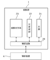
- FIG. 2 is a schematic view showing an example of the internal configuration of the projection unit 1 shown in FIG.
- the projection unit 1 includes a light source 21, an optical modulation unit 22, a projection optical system 23, and a control circuit 24.
- the light source 21 includes a light emitting element such as a laser or an LED (Light Emitting Diode), and emits white light, for example.
- a light emitting element such as a laser or an LED (Light Emitting Diode), and emits white light, for example.
- the light modulation unit 22 modulates each color light emitted from the light source 21 and separated into three colors of red, blue, and green by a color separation mechanism (not shown) based on image information, and emits each color image. It is composed of a liquid crystal panel. Red, blue, and green filters may be mounted on each of the three liquid crystal panels, and the white light emitted from the light source 21 may be modulated by each liquid crystal panel to emit each color image.
- the projection optical system 23 receives light from the light source 21 and the light modulation unit 22, and includes, for example, a relay optical system including at least one lens. The light that has passed through the projection optical system 23 is projected onto the screen 6.
- the control circuit 24 projects an image based on the display data on the screen 6 by controlling the light source 21, the optical modulation unit 22, and the projection optical system 23 based on the display data input from the control device 4. Let me.
- the display data input to the control circuit 24 is composed of three components: red display data, blue display data, and green display data.
- control circuit 24 expands or contracts the projection area 11 (see FIG. 1) of the projection unit 1 by changing the projection optical system 23 based on the command input from the control device 4. Further, the control device 4 may move the projection area 11 of the projection unit 1 by changing the projection optical system 23 based on the operation from the user received by the operation reception unit 2.
- the projection device 10 includes a shift mechanism that mechanically or optically moves the projection region 11 while maintaining the image circle of the projection optical system 23.
- the image circle of the projection optical system 23 is a region in which the projected light incident on the projection optical system 23 appropriately passes through the projection optical system 23 from the points of light loss, color separation, peripheral curvature, and the like.
- the shift mechanism is realized by at least one of an optical system shift mechanism that shifts the optical system and an electronic shift mechanism that performs electron shift.
- the optical system shift mechanism is, for example, a mechanism for moving the projection optical system 23 in a direction perpendicular to the optical axis (see, for example, FIGS. 3 and 4), or an optical modulation unit 22 instead of moving the projection optical system 23. It is a mechanism that moves in the direction perpendicular to the axis. Further, the optical system shift mechanism may be a combination of the movement of the projection optical system 23 and the movement of the optical modulation unit 22.
- the electronic shift mechanism is a mechanism that shifts the pseudo projection region 11 by changing the range in which light is transmitted in the optical modulation unit 22.
- the projection device 10 may include a projection direction changing mechanism that moves the projection area 11 together with the image circle of the projection optical system 23.
- the projection direction changing mechanism is a mechanism that changes the projection direction of the projection unit 1 by changing the direction of the projection unit 1 by mechanical rotation (see, for example, FIGS. 3 and 4).
- the projection optical system 23 constitutes an optical system having variable optical characteristics.
- the optical characteristic of the projection optical system 23 is, for example, the angle of view of the image projected by the projection optical system 23 (that is, the focal length of the projection optical system 23).
- the projection optical system 23 having a variable angle of view can be realized, for example, by including a zoom lens having a variable focal length in the projection optical system 23.
- the projection optical system 23 having a variable angle of view can be realized by making the lens included in the projection optical system 23 interchangeable.
- the optical characteristics of the projection optical system 23 may be the projection direction according to the rotation of at least a part (for example, the projection direction changing mechanism) of the projection optical system 23.
- the optical characteristic of the projection optical system 23 may be an image circle (for example, size or shape) of the projection optical system 23.
- the optical characteristics of the projection optical system 23 may include a plurality of these optical characteristics.
- FIG. 3 is a schematic view showing an external configuration of the projection device 10.
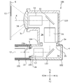
- FIG. 4 is a schematic cross-sectional view of the optical unit 106 of the projection device 10 shown in FIG.
- FIG. 4 shows a cross section of the light emitted from the main body 101 shown in FIG. 3 along the optical path.
- the projection device 10 includes a main body portion 101 and an optical unit 106 provided so as to project from the main body portion 101.
- the operation reception unit 2, the control device 4, the light source 21, the light modulation unit 22, and the control circuit 24 in the projection unit 1 are provided in the main body 101.
- the projection optical system 23 in the projection unit 1 is provided in the optical unit 106.
- the optical unit 106 includes a first member 102 supported by the main body 101 and a second member 103 supported by the first member 102.
- the first member 102 and the second member 103 may be integrated members.
- the optical unit 106 may be detachably configured (in other words, interchangeable) on the main body 101.
- the main body 101 has a housing 15 (see FIG. 4) in which an opening 15a (see FIG. 4) for passing light is formed in a portion connected to the optical unit 106.
- a light source 21 and an optical modulation unit 22 Inside the housing 15 of the main body 101, as shown in FIG. 3, a light source 21 and an optical modulation unit 22 (a light modulation unit 22 that spatially modulates the light emitted from the light source 21 based on input image data to generate an image).
- An optical modulation unit 12 including (see FIG. 2) is provided inside the housing 15 of the main body 101.
- the light emitted from the light source 21 is incident on the optical modulation unit 22 of the optical modulation unit 12, and is spatially modulated by the optical modulation unit 22 and emitted.
- the image formed by the light spatially modulated by the optical modulation unit 12 passes through the opening 15a of the housing 15, is incident on the optical unit 106, and is projected onto the screen 6 as a projection object. Then, the image G1 becomes visible to the observer.
- the optical unit 106 includes a first member 102 having a hollow portion 2A connected to the inside of the main body 101, a second member 103 having a hollow portion 3A connected to the hollow portion 2A, and a hollow portion 2A.
- the first optical system 121 and the reflecting member 122 arranged, the second optical system 31, the reflecting member 32, the third optical system 33, and the lens 34 arranged in the hollow portion 3A, the shift mechanism 105, and the projection direction change.
- the mechanism 104 is provided.
- the first member 102 is a member having a rectangular cross-sectional outer shape as an example, and the openings 2a and 2b are formed on surfaces perpendicular to each other.
- the first member 102 is supported by the main body 101 in a state where the opening 2a is arranged at a position facing the opening 15a of the main body 101.
- the light emitted from the light modulation unit 22 of the light modulation unit 12 of the main body 101 passes through the openings 15a and 2a and is incident on the hollow portion 2A of the first member 102.
- the incident direction of the light incident on the hollow portion 2A from the main body portion 101 is described as the direction X1, the opposite direction of the direction X1 is described as the direction X2, and the direction X1 and the direction X2 are collectively referred to as the direction X.
- the direction from the front to the back of the paper and the opposite direction are described as the direction Z.
- the direction from the front to the back of the paper is described as the direction Z1
- the direction from the back to the front of the paper is described as the direction Z2.
- the direction perpendicular to the direction X and the direction Z is described as the direction Y, and among the directions Y, the upward direction in FIG. 4 is described as the direction Y1, and the downward direction in FIG. 4 is described as the direction Y2. ..
- the projection device 10 is arranged so that the direction Y2 is the vertical direction.
- the projection optical system 23 shown in FIG. 2 is composed of a first optical system 121, a reflection member 122, a second optical system 31, a reflection member 32, a third optical system 33, and a lens 34.
- FIG. 4 shows the optical axis K of the projection optical system 23.
- the first optical system 121, the reflecting member 122, the second optical system 31, the reflecting member 32, the third optical system 33, and the lens 34 are arranged along the optical axis K in this order from the optical modulation unit 22 side.
- the first optical system 121 includes at least one lens, and guides light traveling from the main body 101 to the first member 102 in the direction X1 to the reflecting member 122.
- the reflecting member 122 reflects the light incident from the first optical system 121 in the direction Y1.
- the reflective member 122 is composed of, for example, a mirror or the like.
- the first member 102 has an opening 2b formed on the optical path of the light reflected by the reflecting member 122, and the reflected light passes through the opening 2b and proceeds to the hollow portion 3A of the second member 103.
- the second member 103 is a member having a substantially T-shaped cross section, and an opening 3a is formed at a position facing the opening 2b of the first member 102.
- the light from the main body 101 that has passed through the opening 2b of the first member 102 is incident on the hollow portion 3A of the second member 103 through the opening 3a.
- the cross-sectional outer shape of the first member 102 and the second member 103 is arbitrary, and is not limited to the above.
- the second optical system 31 includes at least one lens, and guides the light incident from the first member 102 to the reflecting member 32.
- the reflecting member 32 reflects the light incident from the second optical system 31 in the direction X2 and guides it to the third optical system 33.
- the reflective member 32 is composed of, for example, a mirror or the like.
- the third optical system 33 includes at least one lens, and guides the light reflected by the reflecting member 32 to the lens 34.
- the lens 34 is arranged at this end so as to close the opening 3c formed at the end of the second member 103 on the direction X2 side.
- the lens 34 projects the light incident from the third optical system 33 onto the screen 6.
- the projection direction changing mechanism 104 is a rotation mechanism that rotatably connects the second member 103 to the first member 102.
- the second member 103 is rotatably configured around a rotation axis (specifically, an optical axis K) extending in the direction Y.
- the projection direction changing mechanism 104 is not limited to the arrangement position shown in FIG. 4, as long as the optical system can be rotated. Further, the number of rotation mechanisms is not limited to one, and a plurality of rotation mechanisms may be provided.
- the shift mechanism 105 is a mechanism for moving the optical axis K (in other words, the optical unit 106) of the projection optical system in a direction perpendicular to the optical axis K (direction Y in FIG. 4). Specifically, the shift mechanism 105 is configured so that the position of the first member 102 in the direction Y with respect to the main body 101 can be changed.
- the shift mechanism 105 may be one that manually moves the first member 102 or one that electrically moves the first member 102.
- FIG. 4 shows a state in which the first member 102 is moved to the direction Y1 side as much as possible by the shift mechanism 105. From the state shown in FIG. 4, the first member 102 is moved in the direction Y2 by the shift mechanism 105, so that the center of the image (in other words, the center of the display surface) formed by the optical modulation unit 22 and the optical axis K are aligned with each other. The relative position changes, and the image G1 projected on the screen 6 can be shifted (translated) in the direction Y2.
- the shift mechanism 105 may be a mechanism that moves the optical modulation unit 22 in the direction Y instead of moving the optical unit 106 in the direction Y. Even in this case, the image G1 projected on the screen 6 can be moved in the direction Y2.
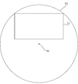
- FIG. 5 is a diagram for explaining an example of shift regulation by the projection device 10.
- the optical axis 51 shown in FIG. 5 is the optical axis of the projection optical system 23.
- the image circle 52 is an image circle of the projection optical system 23.
- the image circle 52 is a region in which the projected light incident on the projection optical system 23 properly passes through the projection optical system 23 from the viewpoints of light loss, color separation, peripheral curvature, and the like.
- the optical axis 51 is located at the center of the image circle 52. Note that FIG. 5 shows the optical axis 51 and the image circle 52 as viewed from a direction parallel to the optical axis 51.
- the control device 4 controls, for example, to regulate the movement of the projection area 11 by the shift mechanism so that the projection area 11 does not deviate from the image circle 52.
- the shift mechanism to which this regulation is applied is, for example, an optical system shift by the above-mentioned optical system shift mechanism.
- the shift mechanism to which this regulation is applied may be an electron shift by the above-mentioned electron shift mechanism, or may be both an optical system shift by the optical system shift mechanism and an electron shift by the electron shift mechanism.
- the position of the projection area 11 is set so that the center of the projection area 11 (the intersection of the diagonal lines of the projection area 11) coincides with the optical axis 51 in the initial state, and the control device 4 receives the operation.
- the projection area 11 is moved by the shift mechanism according to the user operation for the unit 2.
- the projection area 11 moves upward (upward in FIG. 5), and the upper right corner and the upper left corner of the projection area 11 reach the end of the image circle 52.
- the ends of the projection area 11 deviate from the image circle 52, and the projection quality such as a drop in the amount of light is deteriorated at the end of the projection area 11. Occurs.
- control device 4 controls the movement of the projection area 11 so that the projection area 11 does not move upward any more.
- the control device 4 does not move the projection area 11 upward even if it accepts a user operation for further moving the projection area 11 upward.
- control device 4 may notify the user by voice, screen display, or the like that the projection area 11 cannot be moved upward any more. Then, when the control device 4 further accepts the user operation of moving the projection area 11 upward, the control device 4 may move the projection area 11 upward.
- the control device 4 determines the current lens of the projection optical system 23, and regulates the movement of the projection region 11 according to the image circle 52 corresponding to the determined lens.
- the projection device 10 even if the optical characteristics of the projection optical system 23 are variable, the movement of the projection region 11 for projecting an image is restricted based on the current optical characteristics of the projection optical system 23. By performing the control, it is possible to suppress deterioration of projection quality such as light falloff, color separation, and peripheral curvature.
- the projection device 10 derives a shift range which is a movable range of the projection region 11 based on the optical characteristics of the projection optical system 23, and regulates the movement of the projection region 11 by the derived shift range.
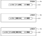
- control device 4 stores at least one of the corresponding information 111 to 116 shown in FIGS. 6 and 7 in the storage medium 4a (see FIG. 1).
- the correspondence information 111 to 116 is created in advance by simulation, experiment, or the like according to the design of the projection optical system 23, and is stored in the storage medium 4a.
- Correspondence information 111 in FIG. 6 is correspondence information indicating a corresponding shift range for a plurality of zoom states.
- the zoom state is the angle of view of the projection optical system 23 including the zoom lens.
- the control device 4 controls, for example, to regulate the movement of the projection region 11 so as not to deviate from the shift range derived based on the angle of view of the current projection optical system 23 and the corresponding information 111.
- Correspondence information 112 in FIG. 6 is correspondence information indicating corresponding shift ranges for a plurality of projection directions.
- the projection direction is the projection direction of the projection optical system 23 due to the rotation of the projection direction changing mechanism 104.
- the control device 4 controls the movement of the projection region 11 so as not to deviate from the shift range derived based on the projection direction of the current projection optical system 23 and the correspondence information 112.
- Correspondence information 113 in FIG. 6 is correspondence information indicating a corresponding shift range for a plurality of combinations of a zoom state and a projection direction.
- the control device 4 controls the movement of the projection area 11 so as not to deviate from the shift range derived based on the current zoom state and projection direction and the correspondence information 113.
- Correspondence information 114 in FIG. 7 is correspondence information indicating a corresponding shift range for a plurality of combinations of a lens ID and a zoom state.
- the lens ID is an identifier of a lens mounted on the projection optical system 23 in which the lens can be exchanged.
- the control device 4 controls the movement of the projection region 11 so as not to deviate from the shift range derived based on the current lens ID and zoom state and the correspondence information 114.
- Correspondence information 115 in FIG. 7 is correspondence information indicating a corresponding shift range for a plurality of combinations of a lens ID and a projection direction.
- the control device 4 controls the movement of the projection region 11 so as not to deviate from the shift range derived based on the current lens ID and projection direction and the correspondence information 115.
- Correspondence information 116 in FIG. 7 is correspondence information indicating a corresponding shift range for a plurality of combinations of a lens ID, a zoom state, and a projection direction.
- the control device 4 controls the movement of the projection area 11 so as not to deviate from the shift range derived based on the current lens ID, the zoom state, the projection direction, and the correspondence information 116.
- the control device 4 moves the projection region 11 based on the information of the optical characteristics of the projection optical system 23 and the shift range which is the movable range of the projection region 11. You may perform control to regulate. Specifically, the control device 4 acquires correspondence information for associating the optical characteristics of the projection optical system 23 with the shift range, and based on the acquired correspondence information and the optical characteristics in the projection optical system 23, Control may be performed to regulate the movement of the projection area 11.
- the control device 4 determines the lens ID of the lens included in the projection optical system 23 and the optical characteristics of the projection optical system 23. Control may be performed to regulate the movement of the projection area 11 based on the combination of and. Specifically, the control device 4 acquires correspondence information that associates the combination of the lens ID and the optical characteristics with the shift range, and the acquired correspondence information and the lens ID and projection of the lens included in the projection optical system 23. Control may be performed to regulate the movement of the projection region 11 based on the combination of optical characteristics in the optical system 23.
- FIG. 8 is a diagram for explaining an example of calculation processing of shift regulation by the projection device 10.
- the rectangle shown by the dotted line indicates the initial position of the projection area 11.
- the image circle 52 changes depending on the lens mounted on the projection optical system 23, for example, when the lens of the projection optical system 23 can be exchanged.
- the radius r is the radius of the image circle 52.
- the radius r of the image circle 52 is stored as the shift range.
- the control device 4 can derive the radius r as the shift range based on the optical characteristics of the projection optical system 23 or the combination of the optical characteristics of the projection optical system 23 and the lens ID.
- the height h is the length of the projection area 11 in the vertical direction.
- the width w is the length of the projection area 11 in the left-right direction. Since the height h and the width w are determined according to the design of the optical modulation unit 22, for example, they are stored in advance in the storage medium 4a of the control device 4. Further, when the control device 4 performs an electron shift in which the projection region 11 is pseudo-changed by changing the range through which light is transmitted in the optical modulation unit 22, the height h and the width w are changed by the electron shift. The height and width of the projection region 11 that has been changed in a pseudo manner may be used.
- V1 in FIG. 7 is the distance between the upper side of the projection area 11 and the optical axis 51 in a state where the upper right corner and the upper left corner of the projection area 11 reach the end of the image circle 52.
- V1 can be calculated by, for example, the following equation (1).
- V1 (r ⁇ 2- (w / 2) ⁇ 2) ⁇ 0.5 ... (1)
- the control device 4 sets the projection area 11 within a range in which the distance between the upper side of the projection area 11 and the optical axis 51 does not become larger than V1 in response to the user operation instructing the projection area 11 to move upward. Controls the movement in the upward direction. As a result, it is possible to prevent the projection area 11 from deviating to the upper side of the image circle 52.
- Vs'in FIG. 6 is the amount of movement of the upper side of the projection area 11 when the projection area 11 is moved from the initial position to the position shown in FIG. Vs'can be calculated by, for example, the following equation (2).
- Vs' V1-0.5h ...
- the control device 4 receives the projection area 11 in a range in which the amount of movement of the projection area 11 from the initial position in the upward direction does not become larger than Vs' in response to the user operation instructing the projection area 11 to move upward. May be controlled to move upward. As a result, it is possible to prevent the projection area 11 from deviating to the upper side of the image circle 52.
- control device 4 regulates the upward movement of the projection region 11 by the ratio of the height h of the projection optical system 23 to the upward movement amount of the projection region 11, so that the projection region 11 is imaged. It may be avoided to deviate to the upper side of the circle 52.
- FIG. 9 is a diagram for explaining another example of the arithmetic processing of the shift regulation by the projection device 10.
- the rectangle shown by the dotted line indicates the initial position of the projection area 11.
- V2 in FIG. 9 is the distance between the upper side of the projection area 11 and the optical axis 51 in a state where the upper side of the projection area 11 reaches the upper end of the image circle 52.
- V2 can be calculated by, for example, the following equation (3).
- control device 4 has a projection area within a range in which the distance between the upper side of the projection area 11 and the optical axis 51 does not become larger than V2 in response to a user operation instructing the projection area 11 to move upward. Control is performed to move 11 upward. As a result, it is possible to prevent the entire upper side of the projection area 11 from deviating to the upper side of the image circle 52.
- Vs'in FIG. 9 is the amount of movement of the upper side of the projection area 11 when the projection area 11 is moved from the initial position to the position shown in FIG. Vs'in FIG. 9 can be calculated by, for example, the following equation (4).
- Vs' V2-0.5h ... (4)
- the control device 4 has a range in which the amount of upward movement of the projection area 11 from the initial position does not become larger than Vs'in FIG. 9 in response to the user operation instructing the projection area 11 to move upward. Control may be performed to move the projection area 11 upward. As a result, it is possible to prevent the entire upper side of the projection area 11 from deviating to the upper side of the image circle 52.
- control device 4 regulates the upward movement of the projection region 11 by the ratio of the height h of the projection optical system 23 to the upward movement amount of the projection region 11, thereby regulating the upper side of the projection region 11. It may be avoided that all of the above deviates to the upper side of the image circle 52.
- control device 4 may set the shift range in which the projection area 11 can be moved to a range in which a part of the projection area 11 can deviate from the image circle 52. As a result, the projection quality of a part of the projection area 11 may be deteriorated, but the movable shift range of the projection area 11 can be widened.
- the shift range in which the projection area 11 can be moved is not limited to that shown in FIGS. 8 and 9, and the projection quality of a part of the projection area 11 can be arbitrarily set within an acceptable range.
- the control device 4 may be able to switch the shift range in which the projection area 11 can be moved. This shift range switching may be performed in response to the reception of user operations via the operation reception unit 2, or is automatically performed based on various information such as the contents of the projected image and the installation status of the projection device 10. It may be done.
- control device 4 also performs control for restricting each movement of the projection area 11 in the downward direction, the left direction, and the right direction. Further, the control device 4 may perform control that similarly regulates each movement of the projection region 11 in the oblique direction.
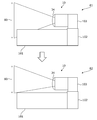
- control device 4 may control the movement of the projection area 11 so that the projection area 11 is not obstructed (vignetting) by the main body 101 or the like of the projection device 10 (see, for example, FIGS. 10 and 11). ).
- FIG. 10 is a diagram showing an example of regulation of movement of the projection region 11 based on the lens ID of the lens mounted on the projection optical system 23.
- the control device 4 may perform control to regulate the movement of the projection region 11 based on the lens ID of the lens mounted on the projection optical system 23. For example, depending on the lens mounted on the projection optical system 23, the image circle of the projection optical system 23 may be blocked by the main body 101 or the like.
- the shift range 80 is a range in the vertical direction (Y direction in FIG. 2) in which the projection region 11 can be moved, and is a range in the vertical direction of the image circle of the projection optical system 23 in the state 81.
- the storage medium 4a stores the correspondence information between the lens ID of the lens mounted on the projection optical system 23 and the shift range.
- the control device 4 acquires the lens ID of the lens mounted on the projection optical system 23, derives the shift range corresponding to the acquired lens ID from the correspondence information of the storage medium 4a, and determines the shift range of the projection area 11 according to the derived shift range. Controls movement.
- the shift range 80 is reduced so as not to include the portion blocked by the main body 101. Then, the control device 4 can prevent the projection area 11 from being obstructed by the main body 101 by moving the projection area 11 in the vertical direction within the reduced shift range 80.
- the storage medium 4a may store the correspondence information between the combination of the lens ID and the projection direction of the projection optical system 23 and the shift range.
- the control device 4 controls the movement of the projection region 11 by the shift range corresponding to the combination of the lens ID and the projection direction of the projection optical system 23.
- Such control is performed, for example, in the correspondence information 115, 116 (see FIG. 7) that associates the combination of the lens ID and the projection direction of the projection optical system 23 with the shift range, the characteristics of the lens indicated by the lens ID, and the projection optical system 23.
- This can be realized by setting a range that is not blocked by the main body 101 or the like as a shift range according to the projection direction of the lens.
- FIG. 11 is a diagram showing an example of movement of the projection region 11 based on a change in the projection direction of the projection optical system 23.
- the projection direction of the projection optical system 23 is opposite to that of the main body 101.
- the image circle of the projection optical system 23 is not blocked by the main body 101. Therefore, in the above correspondence information, for example, a shift range corresponding to the image circle is preset for the projection direction shown in the state 91. NS. Therefore, the control device 4 controls the movement of the projection region 11 within the image circle of the projection optical system 23.
- the state 92 is obtained.
- the image circle of the projection optical system 23 is blocked by the main body 101, as in the state 81 of FIG. Therefore, in the above correspondence information, a shift range narrower than, for example, an image circle is preset for the projection direction shown in the state 92.
- control device 4 reduces the shift range 80 so as not to include the portion blocked by the main body 101.
- the state becomes 93, and it is possible to prevent the projection area 11 from being blocked by the main body 101 as in the state 82 of FIG.
- the control device 4 shifts the projection area 11 to the shift range 80. Controls the movement so that it fits. Then, when the control device 4 moves the projection area 11 in response to the change in the optical characteristics of the projection optical system 23 in this way, the control device 4 stores the projection area 11 before the change in the storage medium 4a (memory). back.
- the state 93 when the projection direction of the projection optical system 23 changes by 180 degrees due to the rotation of the projection direction changing mechanism 104, the state becomes the state 94. In the state 94, the shift range 80 is reduced even though the image circle of the projection optical system 23 is not blocked by the main body 101.
- the control device 4 returns the shift range 80 to the original range based on the correspondence information between the projection direction and the shift range. As a result, it is possible to return to the state 91 and widen the shift range 80 in which the projection area 11 can be moved. Then, when the projection direction of the projection optical system 23 changes and returns to the projection direction before the change, the control device 4 stores the projection area 11 in the storage medium 4a. Controls to return to the position.
- the shift range which is the movable range of the projection region 11, is not limited to the image circle of the projection optical system 23, and the projection light by the projection device 10 (for example, the main body 101).
- the range may be determined according to the shielding.
- the projection region 11 deviates from the shift range according to the projection direction of the current projection optical system 23 in response to a change in the optical characteristics of the projection optical system 23. Controls the movement of the projection area 11 so that the projection area 11 falls within the shift range according to the projection direction of the current projection optical system 23.
- the movement of the projection region 11 is restricted according to the change in the optical characteristics of the projection optical system 23, and the projection optical system 23 is further subjected to the optical characteristics in a state where the projection region 11 is moved accordingly.
- control is performed to return the projection area 11 to the projection area 11 before the change.
- control device 4 moves the projection area 11 in response to a change in the optical characteristics of the projection optical system 23
- the control device 4 stores the projection area 11 before the change in the storage medium 4a.
- the control device 4 returns the projection area 11 to the original position stored in the storage medium 4a.
- the projection area 11 can be restored when the reason for the restriction is resolved.
- the control device 4 automatically moves the projection area 11 based on various information. May be good.
- an image pickup device for imaging the screen 6 is provided in the projection device 10, and the control device 4 controls the movement of the projection region 11 to the range of the screen 6 specified by the processing based on the image obtained by the image pickup of the image pickup device. You may go.
- the control device 4 is not limited to the configuration in which the shift range according to the projection direction of the projection optical system 23 is obtained and set in advance by simulation, experiment, or the like, and the control device 4 controls the projection direction of the projection optical system 23, the shape of the main body 101, and the shape of the main body 101.
- the configuration may be calculated based on the optical information of the projection optical system 23 or the like.
- FIGS. 2, 3 and 11 The configuration shown in FIGS. 2, 3 and 11 has been described as a configuration of the projection device 10 including a projection direction as a variable optical characteristic in the optical system, but the present invention is not limited to this, and for example, the lens of the projection optical system is replaced.
- various projection devices 10 can be configured in which the range of the image circle blocked by the main body 101 or the like changes according to the lens mounted on the projection optical system.
- the configuration shown in FIG. 10 has been described as a configuration of the projection device 10 in which the lens of the projection optical system can be exchanged, but the configuration is not limited to this. It is possible to configure various projection devices 10 in which the blocked range changes.
- a projection device that projects an image using an optical system with variable optical characteristics. It has a processor that controls movement of a projection region on which the image is projected based on the optical characteristics in the optical system. Projection device.
- the projection device according to the above.
- the processor performs the control based on the information of the optical characteristics and the movable range of the projection region. Projection device.
- the projection device Acquire the correspondence information that associates the optical characteristics with the movable range of the projection area, and obtains the correspondence information.
- the control is performed based on the acquired correspondence information and the optical characteristics in the optical system. Projection device.
- the projection device according to any one of (1) to (4).
- the optical characteristics include a projection direction corresponding to the rotation of at least a part of the optical system. Projection device.
- the projection device according to any one of (1) to (5).
- the above optical characteristics include an image circle. Projection device.
- the projection device according to any one of (1) to (6).
- the lens included in the above optical system can be replaced,
- the processor performs the control based on a combination of the identifier of the lens included in the optical system and the optical characteristics in the optical system. Projection device.
- the projection device Acquire the correspondence information that associates the combination of the lens identifier and the optical characteristics with the movable range of the projection region.
- the control is performed based on the acquired correspondence information, the identifier of the lens included in the optical system, and the combination of the optical characteristics in the optical system. Projection device.
- the projection device according to (3) or (8).
- the movable range of the projection area is a range determined according to the shielding of the projected light by the projection device. Projection device.
- the projection device according to any one of (1) to (9).
- the processor controls the movement of the projection region in response to a change in the optical characteristics. Projection device.
- the projection device according to any one of (1) to (12). It has a shift mechanism that moves the projection area.
- the processor performs the control that regulates the movement of the projection region by the shift mechanism. Projection device.
- the processor of the projection device controls the movement of the projection region on which the image is projected based on the optical characteristics in the optical system. Projection method.
- the processor performs the control based on the information of the optical characteristics and the movable range of the projection region. Projection method.
- the projection method according to the above Acquire the correspondence information that associates the optical characteristics with the movable range of the projection area, and obtains the correspondence information.
- the control is performed based on the acquired correspondence information and the optical characteristics in the optical system. Projection method.
- the optical characteristics include a projection direction corresponding to the rotation of at least a part of the optical system. Projection method.
- the lens included in the above optical system can be replaced,
- the processor performs the control based on a combination of the identifier of the lens included in the optical system and the optical characteristics in the optical system. Projection method.
- the projection method according to the above.
- the above processor Acquire the correspondence information that associates the combination of the lens identifier and the optical characteristics with the movable range of the projection region.
- the control is performed based on the acquired correspondence information, the identifier of the lens included in the optical system, and the combination of the optical characteristics in the optical system. Projection method.
- the projection method according to (16) or (21) The projection method according to (16) or (21).
- the movable range of the projection area is a range determined according to the shielding of the projected light by the projection device. Projection method.
- the projection method according to any one of (14) to (22).
- the processor controls the movement of the projection region in response to a change in the optical characteristics. Projection method.
- the processor changes the projection region to the optical characteristics before the change when the movement of the projection region is restricted according to the change in the optical characteristics and the optical characteristics further change to return to the optical characteristics before the change. Control to return to the projection area before the change, Projection method.
- the projection method according to any one of (14) to (25).
- the projection device has a shift mechanism for moving the projection area.
- the processor performs the control that regulates the movement of the projection region by the shift mechanism. Projection method.
- a control program for a projection device that projects an image using an optical system with variable optical characteristics. Based on the optical characteristics in the optical system, control is performed to regulate the movement of the projection region on which the image is projected.
- a control program that lets a computer perform processing.
- Projection unit 2 Operation reception unit 2A, 3A Hollow part 2a, 2b, 3a, 3c, 15a Opening 4 Control device 4a Storage medium 6 Screen 10
- Projection device 11 Projection area 12
- Optical modulation unit 15 Housing 21
- Light source 22 Optical modulation unit 23
- Projection optical system 24 Control circuit 31
- Third optical system 34 Lens 51
- Optical axis 52 Image circle 80 Shift range 81,82,91-94 State 101
- Main body 102
- First member 103
- Second Member 104 Projection direction change mechanism 105
- Shift mechanism 106 Optical unit 111 to 116 Correspondence information 121
Landscapes
- Physics & Mathematics (AREA)
- General Physics & Mathematics (AREA)
- Optics & Photonics (AREA)
- Engineering & Computer Science (AREA)
- Multimedia (AREA)
- Signal Processing (AREA)
- Projection Apparatus (AREA)
- Transforming Electric Information Into Light Information (AREA)
Priority Applications (3)
| Application Number | Priority Date | Filing Date | Title |
|---|---|---|---|
| CN202180015601.8A CN115136071B (zh) | 2020-02-21 | 2021-01-29 | 投影装置、投影方法及存储介质 |
| JP2022501747A JP7300054B2 (ja) | 2020-02-21 | 2021-01-29 | 投影装置、投影方法、及び制御プログラム |
| US17/885,100 US12461332B2 (en) | 2020-02-21 | 2022-08-10 | Projection apparatus, projection method, and control program |
Applications Claiming Priority (2)
| Application Number | Priority Date | Filing Date | Title |
|---|---|---|---|
| JP2020-028504 | 2020-02-21 | ||
| JP2020028504 | 2020-02-21 |
Related Child Applications (1)
| Application Number | Title | Priority Date | Filing Date |
|---|---|---|---|
| US17/885,100 Continuation US12461332B2 (en) | 2020-02-21 | 2022-08-10 | Projection apparatus, projection method, and control program |
Publications (1)
| Publication Number | Publication Date |
|---|---|
| WO2021166608A1 true WO2021166608A1 (ja) | 2021-08-26 |
Family
ID=77390942
Family Applications (1)
| Application Number | Title | Priority Date | Filing Date |
|---|---|---|---|
| PCT/JP2021/003430 Ceased WO2021166608A1 (ja) | 2020-02-21 | 2021-01-29 | 投影装置、投影方法、及び制御プログラム |
Country Status (4)
| Country | Link |
|---|---|
| US (1) | US12461332B2 (https=) |
| JP (1) | JP7300054B2 (https=) |
| CN (1) | CN115136071B (https=) |
| WO (1) | WO2021166608A1 (https=) |
Cited By (1)
| Publication number | Priority date | Publication date | Assignee | Title |
|---|---|---|---|---|
| WO2024224924A1 (ja) * | 2023-04-24 | 2024-10-31 | 富士フイルム株式会社 | 投影装置、制御方法、及び制御プログラム |
Citations (5)
| Publication number | Priority date | Publication date | Assignee | Title |
|---|---|---|---|---|
| JP2018021943A (ja) * | 2016-08-01 | 2018-02-08 | セイコーエプソン株式会社 | プロジェクター、及び、プロジェクターの制御方法 |
| WO2018055964A1 (ja) * | 2016-09-23 | 2018-03-29 | 富士フイルム株式会社 | 投射レンズ及びプロジェクタ |
| JP2018151442A (ja) * | 2017-03-10 | 2018-09-27 | キヤノン株式会社 | 画像投射装置 |
| JP2020008799A (ja) * | 2018-07-12 | 2020-01-16 | 株式会社コシナ | 広角レンズ装置 |
| JP6639619B1 (ja) * | 2018-11-13 | 2020-02-05 | 富士フイルム株式会社 | 投射装置 |
Family Cites Families (3)
| Publication number | Priority date | Publication date | Assignee | Title |
|---|---|---|---|---|
| JP5911285B2 (ja) | 2011-02-28 | 2016-04-27 | キヤノン株式会社 | プロジェクション装置およびプログラム |
| JP6538981B2 (ja) * | 2016-07-21 | 2019-07-03 | 富士フイルム株式会社 | 投写レンズ及びプロジェクタ |
| KR102304338B1 (ko) * | 2017-04-28 | 2021-09-23 | 에스케이텔레콤 주식회사 | 영상 투사 기기 정렬 장치 및 방법 |
-
2021
- 2021-01-29 WO PCT/JP2021/003430 patent/WO2021166608A1/ja not_active Ceased
- 2021-01-29 CN CN202180015601.8A patent/CN115136071B/zh active Active
- 2021-01-29 JP JP2022501747A patent/JP7300054B2/ja active Active
-
2022
- 2022-08-10 US US17/885,100 patent/US12461332B2/en active Active
Patent Citations (5)
| Publication number | Priority date | Publication date | Assignee | Title |
|---|---|---|---|---|
| JP2018021943A (ja) * | 2016-08-01 | 2018-02-08 | セイコーエプソン株式会社 | プロジェクター、及び、プロジェクターの制御方法 |
| WO2018055964A1 (ja) * | 2016-09-23 | 2018-03-29 | 富士フイルム株式会社 | 投射レンズ及びプロジェクタ |
| JP2018151442A (ja) * | 2017-03-10 | 2018-09-27 | キヤノン株式会社 | 画像投射装置 |
| JP2020008799A (ja) * | 2018-07-12 | 2020-01-16 | 株式会社コシナ | 広角レンズ装置 |
| JP6639619B1 (ja) * | 2018-11-13 | 2020-02-05 | 富士フイルム株式会社 | 投射装置 |
Cited By (1)
| Publication number | Priority date | Publication date | Assignee | Title |
|---|---|---|---|---|
| WO2024224924A1 (ja) * | 2023-04-24 | 2024-10-31 | 富士フイルム株式会社 | 投影装置、制御方法、及び制御プログラム |
Also Published As
| Publication number | Publication date |
|---|---|
| US20220382012A1 (en) | 2022-12-01 |
| CN115136071A (zh) | 2022-09-30 |
| JP7300054B2 (ja) | 2023-06-28 |
| US12461332B2 (en) | 2025-11-04 |
| CN115136071B (zh) | 2023-10-27 |
| JPWO2021166608A1 (https=) | 2021-08-26 |
Similar Documents
| Publication | Publication Date | Title |
|---|---|---|
| KR100938029B1 (ko) | 프로젝터 | |
| TWI498598B (zh) | 立體裸視投影裝置及顯示裝置 | |
| CN109212877B (zh) | 光学单元以及具备该光学单元的投影仪 | |
| CN101308252B (zh) | 投影装置和用于该投影装置的投影方法 | |
| US20110063580A1 (en) | Projection display apparatus | |
| JP2006323383A (ja) | 携帯用プロジェクタの光学システム及びこれを用いる移動通信端末機 | |
| CN113366386A (zh) | 投影透镜及投影装置 | |
| WO2021166608A1 (ja) | 投影装置、投影方法、及び制御プログラム | |
| US11889238B2 (en) | Projection apparatus, projection method, and control program | |
| WO2021220608A1 (ja) | 制御方法、投影装置、及び制御プログラム | |
| JP2011112811A (ja) | 画像投射装置 | |
| JP2017227803A (ja) | 画像投写装置及び画像位置調整装置 | |
| JP7350898B2 (ja) | 投影装置、投影方法、及び制御プログラム | |
| JP7623893B2 (ja) | 投影装置及び制御方法 | |
| WO2021181938A1 (ja) | 投影システム、投影方法、及び制御プログラム | |
| TWI838675B (zh) | 光路調整機構 | |
| TWI754955B (zh) | 光路調整機構及其製造方法 | |
| JP6914388B2 (ja) | 投射レンズ及び投射装置 | |
| JP7101316B2 (ja) | 制御装置、投影装置、制御方法、及び制御プログラム | |
| WO2021215124A1 (ja) | 制御方法、投影装置、及び制御プログラム | |
| JP4196965B2 (ja) | 画像表示装置 | |
| WO2022044385A1 (ja) | 調整支援装置、調整支援方法、調整支援プログラム、及び投影システム | |
| WO2020261852A1 (ja) | 投影装置 |
Legal Events
| Date | Code | Title | Description |
|---|---|---|---|
| 121 | Ep: the epo has been informed by wipo that ep was designated in this application |
Ref document number: 21755684 Country of ref document: EP Kind code of ref document: A1 |
|
| ENP | Entry into the national phase |
Ref document number: 2022501747 Country of ref document: JP Kind code of ref document: A |
|
| NENP | Non-entry into the national phase |
Ref country code: DE |
|
| 122 | Ep: pct application non-entry in european phase |
Ref document number: 21755684 Country of ref document: EP Kind code of ref document: A1 |