WO2021166337A1 - ハイブリッド車両における電力線の配索構造 - Google Patents
ハイブリッド車両における電力線の配索構造 Download PDFInfo
- Publication number
- WO2021166337A1 WO2021166337A1 PCT/JP2020/041652 JP2020041652W WO2021166337A1 WO 2021166337 A1 WO2021166337 A1 WO 2021166337A1 JP 2020041652 W JP2020041652 W JP 2020041652W WO 2021166337 A1 WO2021166337 A1 WO 2021166337A1
- Authority
- WO
- WIPO (PCT)
- Prior art keywords
- power line
- battery
- cross member
- traveling
- hybrid vehicle
- Prior art date
- Legal status (The legal status is an assumption and is not a legal conclusion. Google has not performed a legal analysis and makes no representation as to the accuracy of the status listed.)
- Ceased
Links
Images


Classifications
-
- B—PERFORMING OPERATIONS; TRANSPORTING
- B60—VEHICLES IN GENERAL
- B60K—ARRANGEMENT OR MOUNTING OF PROPULSION UNITS OR OF TRANSMISSIONS IN VEHICLES; ARRANGEMENT OR MOUNTING OF PLURAL DIVERSE PRIME-MOVERS IN VEHICLES; AUXILIARY DRIVES FOR VEHICLES; INSTRUMENTATION OR DASHBOARDS FOR VEHICLES; ARRANGEMENTS IN CONNECTION WITH COOLING, AIR INTAKE, GAS EXHAUST OR FUEL SUPPLY OF PROPULSION UNITS IN VEHICLES
- B60K1/00—Arrangement or mounting of electrical propulsion units
- B60K1/04—Arrangement or mounting of electrical propulsion units of the electric storage means for propulsion
-
- H—ELECTRICITY
- H02—GENERATION; CONVERSION OR DISTRIBUTION OF ELECTRIC POWER
- H02G—INSTALLATION OF ELECTRIC CABLES OR LINES, OR OF COMBINED OPTICAL AND ELECTRIC CABLES OR LINES
- H02G3/00—Installations of electric cables or lines or protective tubing therefor in or on buildings, equivalent structures or vehicles
- H02G3/36—Installations of cables or lines in walls, floors or ceilings
- H02G3/38—Installations of cables or lines in walls, floors or ceilings the cables or lines being installed in preestablished conduits or ducts
- H02G3/383—Installations of cables or lines in walls, floors or ceilings the cables or lines being installed in preestablished conduits or ducts in floors
-
- B—PERFORMING OPERATIONS; TRANSPORTING
- B60—VEHICLES IN GENERAL
- B60R—VEHICLES, VEHICLE FITTINGS, OR VEHICLE PARTS, NOT OTHERWISE PROVIDED FOR
- B60R16/00—Electric or fluid circuits specially adapted for vehicles and not otherwise provided for; Arrangement of elements of electric or fluid circuits specially adapted for vehicles and not otherwise provided for
- B60R16/02—Electric or fluid circuits specially adapted for vehicles and not otherwise provided for; Arrangement of elements of electric or fluid circuits specially adapted for vehicles and not otherwise provided for electric constitutive elements
- B60R16/0207—Wire harnesses
- B60R16/0215—Protecting, fastening and routing means therefor
-
- B—PERFORMING OPERATIONS; TRANSPORTING
- B60—VEHICLES IN GENERAL
- B60K—ARRANGEMENT OR MOUNTING OF PROPULSION UNITS OR OF TRANSMISSIONS IN VEHICLES; ARRANGEMENT OR MOUNTING OF PLURAL DIVERSE PRIME-MOVERS IN VEHICLES; AUXILIARY DRIVES FOR VEHICLES; INSTRUMENTATION OR DASHBOARDS FOR VEHICLES; ARRANGEMENTS IN CONNECTION WITH COOLING, AIR INTAKE, GAS EXHAUST OR FUEL SUPPLY OF PROPULSION UNITS IN VEHICLES
- B60K11/00—Arrangement in connection with cooling of propulsion units
- B60K11/02—Arrangement in connection with cooling of propulsion units with liquid cooling
- B60K11/04—Arrangement or mounting of radiators, radiator shutters, or radiator blinds
-
- B—PERFORMING OPERATIONS; TRANSPORTING
- B60—VEHICLES IN GENERAL
- B60K—ARRANGEMENT OR MOUNTING OF PROPULSION UNITS OR OF TRANSMISSIONS IN VEHICLES; ARRANGEMENT OR MOUNTING OF PLURAL DIVERSE PRIME-MOVERS IN VEHICLES; AUXILIARY DRIVES FOR VEHICLES; INSTRUMENTATION OR DASHBOARDS FOR VEHICLES; ARRANGEMENTS IN CONNECTION WITH COOLING, AIR INTAKE, GAS EXHAUST OR FUEL SUPPLY OF PROPULSION UNITS IN VEHICLES
- B60K6/00—Arrangement or mounting of plural diverse prime-movers for mutual or common propulsion, e.g. hybrid propulsion systems comprising electric motors and internal combustion engines
- B60K6/20—Arrangement or mounting of plural diverse prime-movers for mutual or common propulsion, e.g. hybrid propulsion systems comprising electric motors and internal combustion engines the prime-movers consisting of electric motors and internal combustion engines, e.g. HEVs
- B60K6/22—Arrangement or mounting of plural diverse prime-movers for mutual or common propulsion, e.g. hybrid propulsion systems comprising electric motors and internal combustion engines the prime-movers consisting of electric motors and internal combustion engines, e.g. HEVs characterised by apparatus, components or means specially adapted for HEVs
- B60K6/40—Arrangement or mounting of plural diverse prime-movers for mutual or common propulsion, e.g. hybrid propulsion systems comprising electric motors and internal combustion engines the prime-movers consisting of electric motors and internal combustion engines, e.g. HEVs characterised by apparatus, components or means specially adapted for HEVs characterised by the assembly or relative disposition of components
-
- H—ELECTRICITY
- H02—GENERATION; CONVERSION OR DISTRIBUTION OF ELECTRIC POWER
- H02G—INSTALLATION OF ELECTRIC CABLES OR LINES, OR OF COMBINED OPTICAL AND ELECTRIC CABLES OR LINES
- H02G3/00—Installations of electric cables or lines or protective tubing therefor in or on buildings, equivalent structures or vehicles
- H02G3/02—Details
- H02G3/04—Protective tubing or conduits, e.g. cable ladders or cable troughs
- H02G3/0406—Details thereof
-
- H—ELECTRICITY
- H02—GENERATION; CONVERSION OR DISTRIBUTION OF ELECTRIC POWER
- H02G—INSTALLATION OF ELECTRIC CABLES OR LINES, OR OF COMBINED OPTICAL AND ELECTRIC CABLES OR LINES
- H02G3/00—Installations of electric cables or lines or protective tubing therefor in or on buildings, equivalent structures or vehicles
- H02G3/30—Installations of cables or lines on walls, floors or ceilings
-
- B—PERFORMING OPERATIONS; TRANSPORTING
- B60—VEHICLES IN GENERAL
- B60K—ARRANGEMENT OR MOUNTING OF PROPULSION UNITS OR OF TRANSMISSIONS IN VEHICLES; ARRANGEMENT OR MOUNTING OF PLURAL DIVERSE PRIME-MOVERS IN VEHICLES; AUXILIARY DRIVES FOR VEHICLES; INSTRUMENTATION OR DASHBOARDS FOR VEHICLES; ARRANGEMENTS IN CONNECTION WITH COOLING, AIR INTAKE, GAS EXHAUST OR FUEL SUPPLY OF PROPULSION UNITS IN VEHICLES
- B60K11/00—Arrangement in connection with cooling of propulsion units
- B60K11/02—Arrangement in connection with cooling of propulsion units with liquid cooling
-
- B—PERFORMING OPERATIONS; TRANSPORTING
- B60—VEHICLES IN GENERAL
- B60K—ARRANGEMENT OR MOUNTING OF PROPULSION UNITS OR OF TRANSMISSIONS IN VEHICLES; ARRANGEMENT OR MOUNTING OF PLURAL DIVERSE PRIME-MOVERS IN VEHICLES; AUXILIARY DRIVES FOR VEHICLES; INSTRUMENTATION OR DASHBOARDS FOR VEHICLES; ARRANGEMENTS IN CONNECTION WITH COOLING, AIR INTAKE, GAS EXHAUST OR FUEL SUPPLY OF PROPULSION UNITS IN VEHICLES
- B60K15/00—Arrangement in connection with fuel supply of combustion engines or other fuel consuming energy converters, e.g. fuel cells; Mounting or construction of fuel tanks
- B60K15/03—Fuel tanks
-
- B—PERFORMING OPERATIONS; TRANSPORTING
- B60—VEHICLES IN GENERAL
- B60K—ARRANGEMENT OR MOUNTING OF PROPULSION UNITS OR OF TRANSMISSIONS IN VEHICLES; ARRANGEMENT OR MOUNTING OF PLURAL DIVERSE PRIME-MOVERS IN VEHICLES; AUXILIARY DRIVES FOR VEHICLES; INSTRUMENTATION OR DASHBOARDS FOR VEHICLES; ARRANGEMENTS IN CONNECTION WITH COOLING, AIR INTAKE, GAS EXHAUST OR FUEL SUPPLY OF PROPULSION UNITS IN VEHICLES
- B60K1/00—Arrangement or mounting of electrical propulsion units
- B60K1/04—Arrangement or mounting of electrical propulsion units of the electric storage means for propulsion
- B60K2001/0405—Arrangement or mounting of electrical propulsion units of the electric storage means for propulsion characterised by their position
-
- B—PERFORMING OPERATIONS; TRANSPORTING
- B60—VEHICLES IN GENERAL
- B60K—ARRANGEMENT OR MOUNTING OF PROPULSION UNITS OR OF TRANSMISSIONS IN VEHICLES; ARRANGEMENT OR MOUNTING OF PLURAL DIVERSE PRIME-MOVERS IN VEHICLES; AUXILIARY DRIVES FOR VEHICLES; INSTRUMENTATION OR DASHBOARDS FOR VEHICLES; ARRANGEMENTS IN CONNECTION WITH COOLING, AIR INTAKE, GAS EXHAUST OR FUEL SUPPLY OF PROPULSION UNITS IN VEHICLES
- B60K1/00—Arrangement or mounting of electrical propulsion units
- B60K1/04—Arrangement or mounting of electrical propulsion units of the electric storage means for propulsion
- B60K2001/0405—Arrangement or mounting of electrical propulsion units of the electric storage means for propulsion characterised by their position
- B60K2001/0438—Arrangement under the floor
Definitions
- the present invention relates to a power line distribution structure in a hybrid vehicle.
- a traveling motor and an engine are mounted on the front part of the vehicle body, and an IPU (electric machine) composed of a traveling battery, an inverter, etc. is contained in an IPU storage portion formed under the floor at the rear part of the vehicle body. (Electrical equipment for use) is disclosed.
- the traction motor and the IPU are connected under the floor via a three-phase power line, but since a tank storage section is formed in the center under the floor and the fuel tank of the engine is arranged, the power line is Arranged to avoid fuel tanks.
- the power line from the traction motor extends rearward in the center of the vehicle width direction and is drawn into the tank compartment, and extends along the inner wall of the tank compartment so as to bypass the fuel tank. However, it is fixed with a bracket or the like as appropriate. Further, the power line is pulled out from the tank storage part, and again extends rearward at the center in the vehicle width direction and is connected to the IPU.
- Patent Document 1 is a power line distribution structure for connecting an inverter included in an IPU and a traveling motor, but apart from this, an inverter integrated with a traveling battery and a traveling motor.
- a hybrid vehicle that adopts a power line distribution structure that connects to and.
- a hybrid vehicle for example, under the floor of the vehicle body, a battery storage portion is formed on the front side of the cross member connecting the left and right side members to dispose the traveling battery, and the tank is stored on the rear side of the cross member.
- a fuel tank is arranged by forming a portion, and a junction box that relays the electric power from the traveling battery and supplies it to the inverter is arranged on the rear side of the fuel tank.
- the power line connecting the terminal block of the traveling battery and the terminal block of the junction box should avoid the fuel tank as in the technique of Patent Document 1. It will be necessary to route to.
- the power line from the terminal block provided on the rear surface of the traveling battery is drawn into the tank housing, for example, extended to the left along the side wall of the cross member in the tank storage, and further along the side wall of the left side member. It is fixed with a bracket or the like as appropriate while extending to the rear.
- the power line is arranged so as to bypass the fuel tank in the tank storage part, and the power line is further pulled out from the tank storage part and connected to the terminal block of the junction box.
- the present invention has been made to solve such a problem, and an object of the present invention is a traveling battery and a traveling motor via a power line arranged so as to bypass the fuel tank in the tank storage portion. It is an object of the present invention to provide a power line wiring structure in a hybrid vehicle capable of reliably protecting the power line in the event of a side collision by another vehicle in the power line wiring structure connected to the side.
- the power line distribution structure in the hybrid vehicle of the present invention includes a fuel tank arranged in a tank accommodating portion formed between the left and right side members on the lower side of the floor of the vehicle body.
- a traveling battery arranged in a battery accommodating portion arranged side by side with the tank accommodating portion across the cross member connecting the left and right side members, and a vehicle in the front-rear direction with respect to the tank accommodating portion.
- a power line distribution structure in a hybrid vehicle including a traveling motor arranged on the side opposite to the battery housing portion and a power line for supplying electric power from the traveling battery to the traveling motor.
- a part of the tank accommodating portion is composed of the left and right side members and the cross member, and the cross member is such that the power line bypasses either the left or right side of the fuel tank from the terminal block of the traveling battery. It is characterized in that an extra length region having a slack is formed in a region along the side wall of the cross member while extending from the side wall of the cross member along the side wall of either the left or right side member. (Claim 1).
- the power line allocation structure of the hybrid vehicle configured in this way, for example, another vehicle collides from either the left or right side (the side where the power line bypasses the fuel tank) at a front-rear position that matches the traveling battery. If this happens, the traveling battery will be impacted and crushed in the left-right direction, and the terminal block will be displaced to either the left or right. Since the extra length region of the power line is stretched with the positional displacement, the increase in tension generated in the power line is suppressed.
- the power line extends in a mountain shape protruding upward along the side wall of the cross member to have a slack in the extra length region (claim 2).
- the power lines are extended in a mountain shape to form a slackened extra length region.
- the terminal block of the traveling battery is arranged under the cross member (claim 3). According to the power line distribution structure in the hybrid vehicle configured in this way, since the terminal block is located below the cross member, the power line is directly guided from the terminal block to the side wall of the cross member.
- the battery-side connector on the traveling battery side to which the power line-side connector on the power line side is connected is formed on the fuel tank side to the terminal block of the traveling battery, and the power line-side connector is formed on the fuel tank side. It is preferable that the cross member protrudes toward the fuel tank side while being connected to the battery side connector, and the power line extends upward from the protruding portion toward the fuel tank side (claim 4).
- the power line routing structure in the hybrid vehicle configured in this way, the power line is pulled upward from the terminal block and is routed upward on the side wall of the cross member without significantly changing the extension direction.
- the traveling motor is further provided with a cooling pipe for circulating cooling water to cool the traveling motor, and the cooling pipe is drawn from the traveling motor into the tank housing portion to obtain the fuel.
- the cooling pipe is extended at the intersection with the cross. It is preferable that the power line is arranged on the member side and the power line is arranged on the fuel tank side (claim 5).
- the power line can behave according to the position displacement of the terminal block of the traveling battery without being hindered by the cooling pipe at the time of a side collision of another vehicle. ..
- the first protector member is fitted to the cooling pipe and the second protector member is fitted to the power line at the intersection (claim 6).
- the heat of the cooling pipe is blocked by the first and second protector members, so that heat damage to the battery-side power cable is prevented.
- the second protector member extends from the intersection to a region along either the left or right side member (claim 7).
- the power line may be sandwiched between the side member deformed by the impact and the fuel tank at the time of a side collision from either the left or right side of the other vehicle.
- the power line is protected by the second protector member.
- the second protector member is bolted to the floor panel of the vehicle body in a region along either the left or right side member, and the power line is the extra length region. It is preferable that the cross member is fixed to the side wall of the cross member with a clip that comes off by a predetermined load (claim 8).
- the power line allocation structure of the hybrid vehicle configured in this way, periodic shaking of the extra length region due to vibration or the like during vehicle running can be a factor of deteriorating the power cable on the battery side. The situation is prevented by fixing the clip.
- the power line is fitted with a flexible third protector member in the extra length region (claim 9).
- the third protector member fitted to the power line since the third protector member fitted to the power line has flexibility, the behavior of the power line following the positional displacement of the terminal block of the traveling battery. Is possible.
- the power line routing structure in the hybrid vehicle of the present invention, the power line routing structure connecting the traveling battery and the traveling motor side via the power line arranged so as to bypass the fuel tank in the tank housing portion. In the case of a side collision by another vehicle, the power line can be reliably protected.
- FIG. 1 shows the side wall of the front floor cross member is viewed from the rear, and the arrow view B when the side wall of the left side member is viewed from the right.
- FIG. 4 shows the fixed state of the battery side power cable by a clip.
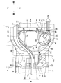
- FIG. 1 is a bottom view showing the rear part of the hybrid vehicle of the embodiment
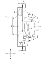
- FIG. 2 is a cross-sectional view showing the positional relationship of the drive unit and the power supply unit with respect to the floor when the rear part of the hybrid vehicle is also viewed from the rear.
- the front-back, left-right, and up-down directions are expressed mainly by the driver in the vehicle.
- a pair of left and right side members 3l and 3r are provided on the lower surface of the floor 2 constituting the vehicle body of the hybrid vehicle 1, and the side members 3l and 3r are closed to and from the floor 2, respectively. It forms a cross section and extends in the front-back direction.
- a rear suspension cross member 4 is arranged on the lower side of the floor 2, and both the left and right sides thereof are suspended and supported from the side members 3l and 3r.
- fixed points 5fl, 5fr, 5rl, 5rr are provided as support mounts at the front and rear positions of the left and right side members 3l and 3r, and the front left and right and rear left and right of the rear suspension cross member 4 are fixed points 5fl, respectively. It is suspended and supported from 5fr, 5rl, and 5rr. Further, the left and right sides of the rear suspension cross member 4 extend forward from the fixed points 5fl and 5fr at the front position, and are fastened to the left and right side members 3l and 3r by a pair of bolts 6l and 6r, respectively.
- the left and right rear wheels 7 are supported on the left and right sides of the rear suspension cross member 4 via double wishbone suspensions (not shown). Since the structure of the suspension is well known, the details will not be described, but the suspension is composed of an upper arm, a lower arm, a toe control link, a spring, an absorber and the like.
- a traveling motor 9 as a drive unit 8 On the lower side of the floor 2, on the rear suspension cross member 4, a traveling motor 9 as a drive unit 8, an inverter 10 integrally provided in the traveling motor 9, and a transaxle 11 functioning as a speed reducer are supported mounts (not shown).
- the left and right rear wheels 7 are connected to the transaxle 11 via a pair of left and right drive shafts 12.
- the traveling motor 9 is driven and controlled by the inverter 10. For example, at the time of power running control, the DC power from the traveling battery 34, which will be described later, is converted into three-phase AC power by the inverter 10 and supplied to the traveling motor 9, and the rotation of the traveling motor 9 is decelerated in the transformer axle 11.
- the left and right rear wheels 7 are driven via the drive shaft 12.
- the rotation of the left and right rear wheels 7 is transmitted to the traveling motor 9 via the drive shaft 12 and the transformer axle 11, and the three-phase AC power generated by the traveling motor 9 is converted into DC power by the inverter 10. It is converted and charged to the traveling battery 34.
- a junction box 21, a charger 22, and a DC-AC inverter 23 are mounted on the floor 2 as a power supply unit 20 from the left side.
- the junction box 21 is a device for connecting the traveling battery 34 and various electric loads such as the traveling motor 9, and the charger 22 uses the electric power from the external power source at the charging station or the like as the traveling battery.
- the DC-AC inverter 23 is a device for charging the 34, and is a device that converts the DC power of the traveling battery 34 into 100V AC power to enable home appliances to be used.
- the power supply unit 20 is covered from above by a cover 24, and a third row seat (not shown) is arranged directly above the power supply unit 20.
- the junction box 21 is connected to the charger 22 and the DC-AC inverter 23 via a power cable, respectively. Further, as shown in FIGS. 1 and 2, a terminal block 21a is provided on the lower surface of the junction box 21, is fitted into a through hole 2a formed in the floor 2, and projects downward. One end of the motor-side power cable 25 is connected to the rear surface of the terminal block 21a, and the other end is connected to the left side surface of the terminal block 10a of the inverter 10.
- the front surface of the terminal block 21a of the junction box 21 is connected to the traveling battery 34 via the battery-side power cable 26 (power line).
- the exchange of electric power between the traveling battery 34 and the charger 22, the DC-AC inverter 23, and the inverter 10 of the traveling motor 9 is performed by relaying the junction box 21.
- the DC power from the traveling battery 34 is supplied to the DC-AC inverter 23 via the junction box 21, converted into 100 V AC power, and used for operating home appliances.
- the AC power supplied from the external power source at the charging station or the like is converted into DC power by the charger 22, and the traveling battery 34 is charged via the junction box 21.
- the power running control and the regeneration control of the traveling motor 9 described above are also performed via the junction box 21.
- FIG. 3 is a perspective view showing a state in which power lines are arranged in the tank storage portion when the bottom surface of the rear portion of the vehicle body of the hybrid vehicle 1 is viewed from diagonally rearward.
- front, middle and rear floor cross members 27 to 29 are provided between the left and right side members 3l and 3r, respectively, and the cross members 27 to 29 are provided. It extends in the left-right direction while forming a closed cross section with the lower surface of the floor 2, and both ends thereof are connected to the left and right side members 3l and 3r.
- the fixed points 5fl, 5fr, 5rl, and 5rr that suspend and support the rear suspension cross member 4 are provided at both ends of the central and rear floor cross members 27 to 29.
- the front floor cross member 27 is arranged at a position on the front side of the middle floor cross member 28, and a tank storage portion 30 that opens downward is formed between the front and middle floor cross members 27 and 28 under the floor 2.
- a battery storage portion 31 that opens downward is formed on the front side of the front floor cross member 27.
- the tank storage unit 30 and the battery storage unit 31 are arranged side by side in the front-rear direction.
- a fuel tank 32 is arranged in the tank storage portion 30 and fixed by a pair of brackets 33, and fuel to be supplied to an engine (not shown) mounted on the front portion of the vehicle body is stored inside the fuel tank 32.
- a traveling battery 34 is arranged in the battery housing portion 31, and the periphery thereof is fixed by bolts (not shown).
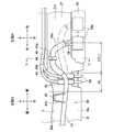
- FIG. 4 is a schematic view showing on one plane the arrow A of FIG. 1 when the side wall of the front floor cross member 27 is viewed from the rear and the arrow B when the side wall of the left side member 3l is viewed from the right.
- the side wall 27a of the front floor cross member 27 and the side wall 3la of the left side member 3l are connected via a curved corner portion 36. ..
- a terminal block 34a is provided on the rear surface of the traveling battery 34, the terminal block 34a is located below the front floor cross member 27, and the tip thereof faces the inside of the tank storage portion 30. It protrudes slightly rearward (fuel tank side) from the side wall 27a of the above.
- the terminals built into the terminal block 34a have an L-shape that extends rearward from the traveling battery 34 and bends upward.
- a connector battery-side connector on the traveling battery side
- a connector (not shown) provided at one end of the battery-side power cable 26 is provided.
- the power line side connector can be connected from above.
- the terminal block 34a is located below the front floor cross member 27, and the connector of the terminal block 34a is open upward. Therefore, the connector of the battery-side power cable 26 connected to the connector of the terminal block 34a protrudes toward the fuel tank 32 side, and the battery-side power cable 26 is pulled out upward from the protruding portion to directly direct the front floor cross member. It is guided to the side wall 27a of the 27, and is further arranged upward on the side wall 27a without significantly changing the extension direction. Although the details will be described later, such an upward pull-out state is intended for arranging the battery-side power cable 26 having a slack.
- the connector structure is not limited to the above as long as this drawer state can be realized.
- an I-shaped terminal is used instead of the L-shaped terminal to form a connector that opens rearward in the terminal block 34a, and the end of the battery-side power cable 26 is orthogonal to the longitudinal direction of the cable. And provide a connector to open.
- the connector is connected to the connector of the terminal block 34a from the rear in a posture in which the battery-side power cable 26 is extended upward. Even in this case, the battery-side power cable 26 is pulled upward from the terminal block 34a.
- the terminal block 34a is separated to the right by the distance L shown in FIG. 4 with respect to the corner portion 36, and the front portion corresponding to this distance L.
- the battery-side power cable 26 Utilizing the region on the side wall 27a of the floor cross member 27, the battery-side power cable 26 is laid out with a slack as described below.
- the slackened portion of the battery-side power cable 26 is referred to as an extra length region 26a, and the region on the side wall 27a corresponding to the distance L to which the extra length region 26a is allocated is referred to as the extra length region. It is called 37.
- the cooling pipe 38 Since the cooling pipe 38, which is also distributed in the tank storage portion 30, is involved in the wiring of the battery-side power cable 26, the wiring state of the cooling pipe 38 will be described first.
- the cooling pipe 38 is provided as a pair of pipelines for circulating cooling water between the traveling motor 9 and a radiator (not shown) arranged at the front of the vehicle body, and the traveling motor 9 is circulated by the circulation of the cooling water. Cooling action is played.
- each cooling pipe 38 is connected to the traveling motor 9 and extends forward, and is drawn into the tank storage portion 30 to the right side (either left or right) of the fuel tank 32. The other) is bypassed and extended forward, and further extended to the left along the side wall 27a of the front floor cross member 27. Then, at the corner portion 36 between the side wall 27a of the front floor cross member 27 and the side wall 3la of the left side member 3l, each cooling pipe 38 is bent downward and pulled out from the tank storage portion 30. At the downwardly bent portion, each cooling pipe 38 is fitted with a pipe-shaped heat insulating material 39 (first protector member) made of a synthetic resin material having heat insulating properties and elasticity. Further, each cooling pipe 38 is bent forward and extends forward beyond the lower surface of the front floor cross member 27, and is connected to a radiator (not shown).
- first protector member made of a synthetic resin material having heat insulating properties and elasticity
- the battery-side power cable 26 is arranged in the tank housing 30 on the opposite side of the cooling pipe 38. That is, one end of the battery-side power cable 26 is connected to the front surface of the terminal block 21a of the junction box 21, the battery-side power cable 26 is pulled into the tank housing portion 30, and the left side (either left or right) of the fuel tank 32 is inserted. It extends forward along the side wall 3la of the left side member 3l so as to detour.
- a pipe-shaped first coating material 40 made of a synthetic resin material having high strength is fitted in the lead-in portion of the battery-side power cable 26 into the tank storage portion 30, and the first coating material 40 is not shown.
- the integrally formed bracket is fixed to the bottom wall 30a or the like of the tank storage portion 30 with bolts.
- a pipe-shaped second covering material 41 (second protector member) made of a synthetic resin material having high strength is fitted to a portion along the side wall 3la of the side member 3l of the battery-side power cable 26.
- a pair of brackets 41a and 41b integrally molded with the second covering material 41 are fixed to the bottom wall 30a of the tank storage portion 30 and the side wall 3la of the side member 3l with bolts 42, respectively.
- the battery-side power cable 26 is maintained in a predetermined shape following the bottom wall 30a of the tank storage portion 30 and the side wall 3la of the side member 3l, and is kept in a predetermined shape when the vehicle is running. Positional displacement due to vibration of the electric power is prevented. Further, at the time of a side collision from the left side of another vehicle, the battery side power cable 26 may be sandwiched between the side member 3l and the fuel tank 32 which are deformed to the right due to the impact. 2. The battery-side power cable 26 is protected by the covering materials 40 and 41 to prevent damage such as disconnection.
- the characteristics of the first and second coating materials 40 and 41 are not limited to the above.
- a urethane material or the like is used to impart high impact absorption to the battery-side power cable. 26 may be protected.
- the second covering material 41 extends forward along the side wall 3la of the side member 3l, curves to the right at the corner 36, and reaches the side wall 27a of the front floor cross member 27. Since the curved portion of the second covering material 41 has a larger curvature than the corner portion 36, a gap is formed between the curved portion and the corner portion 36, and each cooling pipe 38 is fitted in the gap.
- the heat insulating material 39 is located. As a result, at the corner 36, the battery-side power cable 26 and the cooling pipe 38 intersect (intersection points), and the second covering material 41 and the heat insulating material 39 fitted to each intersect or are slightly separated from each other. ing.
- the cooling pipe 38 has a high temperature, the heat is blocked by the heat insulating material 39 and the second coating material 41, so that heat damage to the battery-side power cable 26 is prevented.
- the second covering material 41 and the heat insulating material 39 may rub against each other due to vibration or the like during vehicle running, but this is because direct contact between the battery-side power cable 26 and the cooling pipe 38 is prevented. Problems such as damage to the battery-side power cable 26 due to the above can be prevented.
- the cooling pipe 38 is on the front side (side wall 27a side of the front floor cross member 27), and the battery-side power cable 26 is on the rear side (fuel tank 32). Side). Therefore, at the time of a side collision of another vehicle, which will be described later, the battery side follows the positional displacement of the terminal block 34a of the traveling battery 34 without being hindered by the cooling pipe 38 fixed to the side wall 27a of the front floor cross member 27. The behavior of the power cable 26 is possible.
- the battery-side power cable 26 extends from the end of the second covering material 41 (the end of the corner 36) along the side wall 27a of the front floor cross member 27 on the extra length wiring region 37. It extends to the right. In the extra length distribution region 37, the battery-side power cable 26 is laid out with slack as the extra length region 26a, and the third covering material 43 (third protector member) is fitted to the end of the extra length region 26a.
- the connector provided in the portion is connected to the connector of the terminal block 34a of the traveling battery 34.
- the battery-side power cable 26 is pulled upward from the terminal block 34a, extends upward along the side wall 27a of the front floor cross member 27 in the extra length wiring region 37 of the side wall 27a, and is a side member. It extends downward toward 3 liters, and further extends to the side wall 3 la of the side member 3 liters through the region of the corner 36.
- the battery-side power cable 26 is extended in a mountain shape to form an extra length region 26a, so that the power cable 26 is loosened.
- FIG. 5 is a cross-sectional view taken along the line VV of FIG. 4 showing a fixed state of the battery-side power cable 26 by a clip.
- the portion of the battery-side power cable 26 corresponding to the apex of the extra length region 26a is fixed to the side wall 27a of the front floor cross member 27 by the clip 45.
- the clip 45 is integrally molded from a synthetic resin material, and is composed of a ring-shaped holding portion 45a and a hooking portion 45b provided on one side of the holding portion 45a.
- a third covering material 43 is externally fitted to the holding portion 45a, and the hooking portion 45b is elastically inserted and hooked into the clip hole 46 penetrating the side wall 27a of the front floor cross member 27.
- the extra length region 26a of the battery-side power cable 26 is fixed on the extra length distribution region 37 of the side wall 27a via the clip 45 and the third covering material 43. Periodic shaking of the extra length region 26a due to vibration during vehicle running may cause deterioration of the battery-side power cable 26, but by fixing the clip 45, such a situation can be prevented. ..
- the hooking portion together with the holding portion 45a with the dividing line 47 shown in FIG. 5 as a boundary. 45b is divided into upper and lower parts.
- the procedure for fixing the battery-side power cable 26 is as follows: first, the hooking portion 45b is separated, and then the battery-side power cable 26 to which the third covering material 43 is fitted in advance is placed between the hooking portion 45b from the side. Then, it is inserted into the holding portion 45a.
- the hooking portion 45b is joined, the third covering material 43 is held in the holding portion 45a without a gap, and in this state, the hooking portion 45b is inserted into the clip hole 46 of the side wall 27a.
- the hooking portion 45b expands by its own elasticity and is hooked on the clip hole 46, and the fixing work is completed.
- the hooking of the synthetic resin clip 45 by the hooking portion 45b is weaker than, for example, fastening by the metal bolt 42 for fixing the second covering material 41. For this reason, although the hooking is maintained by the force that the clip 45 normally receives, such as vibration caused by vehicle running, a larger predetermined load (specifically, with the positional displacement of the terminal block 34a described below).
- a larger predetermined load specifically, with the positional displacement of the terminal block 34a described below.
- the third covering material 43 is endowed with characteristics different from those of the first and second covering materials 41. That is, the third coating material 43 is made of a urethane material or the like, and has both high impact absorption and flexibility. Therefore, unlike the first and second covering materials 41 that protect the battery-side power cable 26 with high strength at the time of a side collision of another vehicle, the third covering material 43 absorbs the impact to absorb the impact and thus the internal battery-side power cable. Protect 26. For example, at the time of a side collision of another vehicle, the damaged peripheral member may come into contact with the battery-side power cable 26, but the battery-side power cable 26 is protected by the third covering material 43 to prevent damage.
- the third covering material 43 since the third covering material 43 has high flexibility, the position displacement of the terminal block 34a of the traveling battery 34 is not hindered by the third covering material 43 at the time of a side collision of another vehicle.
- the behavior of the battery-side power cable 26 that follows is possible.
- the protective action at the time of a side collision of another vehicle, which is exerted by the wiring structure of the battery-side power cable 26 configured as described above, will be described.
- the traveling battery 34 is impacted and crushed in the left-right direction.
- the terminal block 34a is displaced to the right.
- the position displacement causes tension in the battery-side power cable 26, and this tension acts as a downward force on the clip 45 fixing the battery-side power cable 26.
- the tension of the battery-side power cable 26 increases according to the position displacement of the terminal block 34a to the right, but the hooking portion 45b of the clip 45 is released before the battery-side power cable 26 is damaged such as disconnection. Will be done.
- the battery-side power cable 26 is not bound by the clip 45, and its tension is sharply reduced.
- the terminal block 34a is further displaced to the right, but the semicircular extra length region 26a is stretched to the right to suppress an increase in the tension of the battery-side power cable 26, resulting in disconnection due to the tension. Damage such as is prevented.
- Such a tension suppressing action is exerted by the extra length region 26a, and is an action that can be reliably obtained regardless of the restrained state of the other regions of the battery-side power cable 26.
- the brackets 41a and 41b fixing the battery side power cable 26 to the side wall 3la of the side member 3l may not be damaged, and the fuel tank 32 may not be deformed due to impact.
- the bracket 41a , 41b keeps the side member 3l fixed to the side wall 3la and causes tension in the battery side power cable 26.
- the behavior of the battery side power cable 26 following the terminal block 34a behaves as the fuel tank 32. In any case, it causes damage such as disconnection.
- the tension generated in the battery-side power cable 26 can be suppressed in any side collision situation without falling into such a situation, and as a result, when a side collision of another vehicle occurs.
- the battery-side power cable 26 can be reliably protected in the above.
- the traveling battery 34, the fuel tank 32, and the traveling motor 9 are arranged in order from the front side of the vehicle body to drive the rear wheels 7, but these arrangements are reversed to the rear side of the vehicle body.
- the traveling battery 34, the fuel tank 32, and the traveling motor 9 may be arranged in this order to drive the front wheels.
- the traveling battery 34 and the junction box 21 are connected via the battery-side power cable 26, but the junction box 21 is omitted and the traveling battery 34 is used for traveling via the battery-side power cable 26. It may be directly connected to the inverter 10 of the motor 9. Further, in the above embodiment, the semicircular extra length region 26a is formed, but the shape is not limited to this and can be arbitrarily changed. For example, a substantially S-shaped extra length region may be formed by combining a semicircle convex on the upper side and a semicircle convex on the lower side.
- the third covering material 43 is fitted in the extra length region 26a of the battery-side power cable 26 and fixed to the side wall 27a of the front floor cross member 27 by the clip 45, but these requirements are not necessarily required. It is not necessary, and either one or both may be omitted.
Landscapes
- Engineering & Computer Science (AREA)
- Mechanical Engineering (AREA)
- Chemical & Material Sciences (AREA)
- Transportation (AREA)
- Combustion & Propulsion (AREA)
- Civil Engineering (AREA)
- Structural Engineering (AREA)
- Architecture (AREA)
- Arrangement Or Mounting Of Propulsion Units For Vehicles (AREA)
- Cooling, Air Intake And Gas Exhaust, And Fuel Tank Arrangements In Propulsion Units (AREA)
- Hybrid Electric Vehicles (AREA)
- Details Of Indoor Wiring (AREA)
- Installation Of Indoor Wiring (AREA)
Priority Applications (4)
| Application Number | Priority Date | Filing Date | Title |
|---|---|---|---|
| US17/761,405 US12233696B2 (en) | 2020-02-19 | 2020-11-09 | Power line routing structure in hybrid vehicle |
| JP2022501628A JP7368795B2 (ja) | 2020-02-19 | 2020-11-09 | ハイブリッド車両における電力線の配索構造 |
| EP20920257.1A EP4108493B1 (en) | 2020-02-19 | 2020-11-09 | Hybrid vehicle with a power line |
| CN202080065889.5A CN115135536A (zh) | 2020-02-19 | 2020-11-09 | 混合动力车辆中的电线的配线构造 |
Applications Claiming Priority (2)
| Application Number | Priority Date | Filing Date | Title |
|---|---|---|---|
| JP2020026519 | 2020-02-19 | ||
| JP2020-026519 | 2020-02-19 |
Publications (1)
| Publication Number | Publication Date |
|---|---|
| WO2021166337A1 true WO2021166337A1 (ja) | 2021-08-26 |
Family
ID=77390562
Family Applications (1)
| Application Number | Title | Priority Date | Filing Date |
|---|---|---|---|
| PCT/JP2020/041652 Ceased WO2021166337A1 (ja) | 2020-02-19 | 2020-11-09 | ハイブリッド車両における電力線の配索構造 |
Country Status (5)
| Country | Link |
|---|---|
| US (1) | US12233696B2 (cg-RX-API-DMAC7.html) |
| EP (1) | EP4108493B1 (cg-RX-API-DMAC7.html) |
| JP (1) | JP7368795B2 (cg-RX-API-DMAC7.html) |
| CN (1) | CN115135536A (cg-RX-API-DMAC7.html) |
| WO (1) | WO2021166337A1 (cg-RX-API-DMAC7.html) |
Cited By (8)
| Publication number | Priority date | Publication date | Assignee | Title |
|---|---|---|---|---|
| EP4159542A1 (en) * | 2021-09-30 | 2023-04-05 | Mazda Motor Corporation | Vehicle-body structure |
| JP2023051652A (ja) * | 2021-09-30 | 2023-04-11 | マツダ株式会社 | 車体構造 |
| JP2023060644A (ja) * | 2021-10-18 | 2023-04-28 | 日産自動車株式会社 | 車両の保護構造 |
| JP2024067311A (ja) * | 2022-11-04 | 2024-05-17 | トヨタ自動車株式会社 | 車両 |
| WO2024257272A1 (ja) * | 2023-06-14 | 2024-12-19 | 日産自動車株式会社 | ハーネスの取付構造 |
| US12233696B2 (en) | 2020-02-19 | 2025-02-25 | Mitsubishi Jidosha Kogyo Kabushiki Kaisha | Power line routing structure in hybrid vehicle |
| WO2025083866A1 (ja) * | 2023-10-20 | 2025-04-24 | 日産自動車株式会社 | 車両のパワーユニット保護構造 |
| CN122275569A (zh) * | 2026-05-29 | 2026-06-26 | 安驰汽车科技(洛阳)有限公司 | 一种车用储能电力设备的自适应机械限位安装架 |
Families Citing this family (4)
| Publication number | Priority date | Publication date | Assignee | Title |
|---|---|---|---|---|
| EP4092880B1 (en) * | 2020-01-17 | 2025-12-31 | Mitsubishi Jidosha Kogyo Kabushiki Kaisha | ELECTRIC VEHICLE WITH AN ARRANGEMENT STRUCTURE COMPRISING A DRIVE UNIT AND AN ELECTRICAL POWER SUPPLY UNIT |
| FR3151553B1 (fr) * | 2023-07-25 | 2025-07-18 | Renault Sas | Arrangement pour véhicule automobile. |
| FR3162681A1 (fr) * | 2024-05-28 | 2025-12-05 | Renault Sas | Dispositif de protection pare-feu pour un véhicule automobile hybride |
| FR3166112A1 (fr) * | 2024-09-10 | 2026-03-13 | Renault Sas | Arrangement pour véhicule automobile. |
Citations (6)
| Publication number | Priority date | Publication date | Assignee | Title |
|---|---|---|---|---|
| JP2007039020A (ja) * | 2005-06-28 | 2007-02-15 | Honda Motor Co Ltd | 車体構造 |
| WO2011135270A1 (fr) * | 2010-04-30 | 2011-11-03 | Peugeot Citroën Automobiles SA | Vehicule hybride comportant une batterie haute tension implantee sous le plancher du vehicule, bloc forme par un reservoir et une batterie haute tension, et procede de remplacement associe |
| JP2012040893A (ja) | 2010-08-12 | 2012-03-01 | Honda Motor Co Ltd | ハイブリッド車両 |
| JP2016052862A (ja) * | 2014-09-04 | 2016-04-14 | 日産自動車株式会社 | 電動車両の車体後部構造 |
| JP2018070076A (ja) * | 2016-11-02 | 2018-05-10 | トヨタ自動車株式会社 | 電気自動車 |
| JP2019151174A (ja) * | 2018-03-01 | 2019-09-12 | 三菱自動車工業株式会社 | 電動車両における電源ユニットの配置構造 |
Family Cites Families (12)
| Publication number | Priority date | Publication date | Assignee | Title |
|---|---|---|---|---|
| JP3571677B2 (ja) * | 2001-09-03 | 2004-09-29 | 本田技研工業株式会社 | ハイブリッド車両用モータの配線構造 |
| JP3815456B2 (ja) * | 2003-04-09 | 2006-08-30 | トヨタ自動車株式会社 | ハイブリッド車両における高圧電線の配策構造 |
| JP4355366B2 (ja) | 2005-11-10 | 2009-10-28 | 日産自動車株式会社 | 車両の強電ハーネス配索構造 |
| JP5660111B2 (ja) * | 2012-11-30 | 2015-01-28 | トヨタ自動車株式会社 | 電気自動車のモータルームにおけるケーブル配索構造 |
| JP6271615B2 (ja) * | 2016-02-12 | 2018-01-31 | 本田技研工業株式会社 | ケーブル構造及び車両 |
| JP6286459B2 (ja) * | 2016-02-12 | 2018-02-28 | 本田技研工業株式会社 | 車両 |
| JP6706507B2 (ja) * | 2016-02-12 | 2020-06-10 | 本田技研工業株式会社 | 車両 |
| JP6357512B2 (ja) * | 2016-09-13 | 2018-07-11 | 本田技研工業株式会社 | ハーネスホルダ、電力機器ユニット及び車両 |
| JP6922763B2 (ja) | 2018-01-30 | 2021-08-18 | トヨタ自動車株式会社 | 車両下部構造 |
| JP2020026159A (ja) | 2018-08-09 | 2020-02-20 | トヨタ自動車株式会社 | 車両下部構造 |
| EP4092880B1 (en) * | 2020-01-17 | 2025-12-31 | Mitsubishi Jidosha Kogyo Kabushiki Kaisha | ELECTRIC VEHICLE WITH AN ARRANGEMENT STRUCTURE COMPRISING A DRIVE UNIT AND AN ELECTRICAL POWER SUPPLY UNIT |
| EP4108493B1 (en) | 2020-02-19 | 2025-01-01 | Mitsubishi Jidosha Kogyo Kabushiki Kaisha | Hybrid vehicle with a power line |
-
2020
- 2020-11-09 EP EP20920257.1A patent/EP4108493B1/en active Active
- 2020-11-09 WO PCT/JP2020/041652 patent/WO2021166337A1/ja not_active Ceased
- 2020-11-09 US US17/761,405 patent/US12233696B2/en active Active
- 2020-11-09 CN CN202080065889.5A patent/CN115135536A/zh active Pending
- 2020-11-09 JP JP2022501628A patent/JP7368795B2/ja active Active
Patent Citations (6)
| Publication number | Priority date | Publication date | Assignee | Title |
|---|---|---|---|---|
| JP2007039020A (ja) * | 2005-06-28 | 2007-02-15 | Honda Motor Co Ltd | 車体構造 |
| WO2011135270A1 (fr) * | 2010-04-30 | 2011-11-03 | Peugeot Citroën Automobiles SA | Vehicule hybride comportant une batterie haute tension implantee sous le plancher du vehicule, bloc forme par un reservoir et une batterie haute tension, et procede de remplacement associe |
| JP2012040893A (ja) | 2010-08-12 | 2012-03-01 | Honda Motor Co Ltd | ハイブリッド車両 |
| JP2016052862A (ja) * | 2014-09-04 | 2016-04-14 | 日産自動車株式会社 | 電動車両の車体後部構造 |
| JP2018070076A (ja) * | 2016-11-02 | 2018-05-10 | トヨタ自動車株式会社 | 電気自動車 |
| JP2019151174A (ja) * | 2018-03-01 | 2019-09-12 | 三菱自動車工業株式会社 | 電動車両における電源ユニットの配置構造 |
Non-Patent Citations (1)
| Title |
|---|
| See also references of EP4108493A4 |
Cited By (12)
| Publication number | Priority date | Publication date | Assignee | Title |
|---|---|---|---|---|
| US12233696B2 (en) | 2020-02-19 | 2025-02-25 | Mitsubishi Jidosha Kogyo Kabushiki Kaisha | Power line routing structure in hybrid vehicle |
| EP4159542A1 (en) * | 2021-09-30 | 2023-04-05 | Mazda Motor Corporation | Vehicle-body structure |
| JP2023051652A (ja) * | 2021-09-30 | 2023-04-11 | マツダ株式会社 | 車体構造 |
| US12286019B2 (en) * | 2021-09-30 | 2025-04-29 | Mazda Motor Corporation | Vehicle-body structure with a battery cover for improved aerodynamic performance |
| JP7775652B2 (ja) | 2021-09-30 | 2025-11-26 | マツダ株式会社 | 車体構造 |
| JP2023060644A (ja) * | 2021-10-18 | 2023-04-28 | 日産自動車株式会社 | 車両の保護構造 |
| JP7664146B2 (ja) | 2021-10-18 | 2025-04-17 | 日産自動車株式会社 | 車両の保護構造 |
| JP2024067311A (ja) * | 2022-11-04 | 2024-05-17 | トヨタ自動車株式会社 | 車両 |
| JP7715125B2 (ja) | 2022-11-04 | 2025-07-30 | トヨタ自動車株式会社 | 車両 |
| WO2024257272A1 (ja) * | 2023-06-14 | 2024-12-19 | 日産自動車株式会社 | ハーネスの取付構造 |
| WO2025083866A1 (ja) * | 2023-10-20 | 2025-04-24 | 日産自動車株式会社 | 車両のパワーユニット保護構造 |
| CN122275569A (zh) * | 2026-05-29 | 2026-06-26 | 安驰汽车科技(洛阳)有限公司 | 一种车用储能电力设备的自适应机械限位安装架 |
Also Published As
| Publication number | Publication date |
|---|---|
| EP4108493A1 (en) | 2022-12-28 |
| US20220371420A1 (en) | 2022-11-24 |
| CN115135536A (zh) | 2022-09-30 |
| US12233696B2 (en) | 2025-02-25 |
| JP7368795B2 (ja) | 2023-10-25 |
| EP4108493B1 (en) | 2025-01-01 |
| JPWO2021166337A1 (cg-RX-API-DMAC7.html) | 2021-08-26 |
| EP4108493A4 (en) | 2023-10-04 |
Similar Documents
| Publication | Publication Date | Title |
|---|---|---|
| JP7368795B2 (ja) | ハイブリッド車両における電力線の配索構造 | |
| US12036858B2 (en) | Arrangement structure of drive unit and power supply unit in electric vehicle | |
| JP7295505B2 (ja) | 車両の駆動ユニット | |
| CN104284791B (zh) | 电动汽车 | |
| JP5446537B2 (ja) | 電気自動車の搭載構造 | |
| JP5516084B2 (ja) | 車載システム回路の充電器搭載構造 | |
| JP7339608B2 (ja) | 電動車両における電源ユニットの配置構造 | |
| JP5018837B2 (ja) | 電気自動車の搭載構造 | |
| JP4924671B2 (ja) | 電気自動車の搭載構造 | |
| CN102555754B (zh) | 车辆的线束设置结构 | |
| JPWO2021166337A5 (cg-RX-API-DMAC7.html) | ||
| WO2013133153A1 (ja) | 電気自動車のハーネス配策構造 | |
| WO2009014254A1 (ja) | 内燃機関および回転電機を動力源として備える車両 | |
| CN106671761A (zh) | 燃料电池的搭载结构 | |
| JP4968292B2 (ja) | 電気自動車の搭載構造 | |
| JP7343457B2 (ja) | 電動車両 | |
| JP2019151174A (ja) | 電動車両における電源ユニットの配置構造 | |
| JP7087834B2 (ja) | 電気機器の車載構造 | |
| JP6614213B2 (ja) | エンジンルーム内のハーネス配索構造 | |
| JP2023136720A (ja) | 電動車両の駆動装置 | |
| US20250269745A1 (en) | Power unit room installing structure | |
| WO2013133151A1 (ja) | 電気自動車のハーネス配策構造 | |
| JP7845299B2 (ja) | エンジンルーム搭載構造 | |
| JP2020203545A (ja) | 車両 | |
| JP6500740B2 (ja) | 電力変換器の車載構造 |
Legal Events
| Date | Code | Title | Description |
|---|---|---|---|
| 121 | Ep: the epo has been informed by wipo that ep was designated in this application |
Ref document number: 20920257 Country of ref document: EP Kind code of ref document: A1 |
|
| ENP | Entry into the national phase |
Ref document number: 2022501628 Country of ref document: JP Kind code of ref document: A |
|
| NENP | Non-entry into the national phase |
Ref country code: DE |
|
| ENP | Entry into the national phase |
Ref document number: 2020920257 Country of ref document: EP Effective date: 20220919 |
|
| WWG | Wipo information: grant in national office |
Ref document number: 17761405 Country of ref document: US |