WO2021161976A1 - フレキシブル配線体、駆動システムおよび撮像装置 - Google Patents
フレキシブル配線体、駆動システムおよび撮像装置 Download PDFInfo
- Publication number
- WO2021161976A1 WO2021161976A1 PCT/JP2021/004696 JP2021004696W WO2021161976A1 WO 2021161976 A1 WO2021161976 A1 WO 2021161976A1 JP 2021004696 W JP2021004696 W JP 2021004696W WO 2021161976 A1 WO2021161976 A1 WO 2021161976A1
- Authority
- WO
- WIPO (PCT)
- Prior art keywords
- actuator
- portions
- movable
- flexible wiring
- movable portion
- Prior art date
- Legal status (The legal status is an assumption and is not a legal conclusion. Google has not performed a legal analysis and makes no representation as to the accuracy of the status listed.)
- Ceased
Links
Images


Classifications
-
- H—ELECTRICITY
- H05—ELECTRIC TECHNIQUES NOT OTHERWISE PROVIDED FOR
- H05K—PRINTED CIRCUITS; CASINGS OR CONSTRUCTIONAL DETAILS OF ELECTRIC APPARATUS; MANUFACTURE OF ASSEMBLAGES OF ELECTRICAL COMPONENTS
- H05K1/00—Printed circuits
- H05K1/02—Details
- H05K1/0277—Bendability or stretchability details
- H05K1/028—Bending or folding regions of flexible printed circuits
-
- H—ELECTRICITY
- H10—SEMICONDUCTOR DEVICES; ELECTRIC SOLID-STATE DEVICES NOT OTHERWISE PROVIDED FOR
- H10W—GENERIC PACKAGES, INTERCONNECTIONS, CONNECTORS OR OTHER CONSTRUCTIONAL DETAILS OF DEVICES COVERED BY CLASS H10
- H10W70/00—Package substrates; Interposers; Redistribution layers [RDL]
- H10W70/60—Insulating or insulated package substrates; Interposers; Redistribution layers
- H10W70/62—Insulating or insulated package substrates; Interposers; Redistribution layers characterised by their interconnections
- H10W70/65—Shapes or dispositions of interconnections
-
- G—PHYSICS
- G03—PHOTOGRAPHY; CINEMATOGRAPHY; ANALOGOUS TECHNIQUES USING WAVES OTHER THAN OPTICAL WAVES; ELECTROGRAPHY; HOLOGRAPHY
- G03B—APPARATUS OR ARRANGEMENTS FOR TAKING PHOTOGRAPHS OR FOR PROJECTING OR VIEWING THEM; APPARATUS OR ARRANGEMENTS EMPLOYING ANALOGOUS TECHNIQUES USING WAVES OTHER THAN OPTICAL WAVES; ACCESSORIES THEREFOR
- G03B5/00—Adjustment of optical system relative to image or object surface other than for focusing
-
- H—ELECTRICITY
- H02—GENERATION; CONVERSION OR DISTRIBUTION OF ELECTRIC POWER
- H02K—DYNAMO-ELECTRIC MACHINES
- H02K41/00—Propulsion systems in which a rigid body is moved along a path due to dynamo-electric interaction between the body and a magnetic field travelling along the path
- H02K41/02—Linear motors; Sectional motors
- H02K41/035—DC motors; Unipolar motors
- H02K41/0352—Unipolar motors
- H02K41/0354—Lorentz force motors, e.g. voice coil motors
-
- H—ELECTRICITY
- H02—GENERATION; CONVERSION OR DISTRIBUTION OF ELECTRIC POWER
- H02N—ELECTRIC MACHINES NOT OTHERWISE PROVIDED FOR
- H02N1/00—Electrostatic generators or motors using a solid moving electrostatic charge carrier
- H02N1/002—Electrostatic motors
- H02N1/006—Electrostatic motors of the gap-closing type
-
- H—ELECTRICITY
- H04—ELECTRIC COMMUNICATION TECHNIQUE
- H04M—TELEPHONIC COMMUNICATION
- H04M1/00—Substation equipment, e.g. for use by subscribers
- H04M1/02—Constructional features of telephone sets
- H04M1/0202—Portable telephone sets, e.g. cordless phones, mobile phones or bar type handsets
- H04M1/026—Details of the structure or mounting of specific components
- H04M1/0264—Details of the structure or mounting of specific components for a camera module assembly
-
- H—ELECTRICITY
- H05—ELECTRIC TECHNIQUES NOT OTHERWISE PROVIDED FOR
- H05K—PRINTED CIRCUITS; CASINGS OR CONSTRUCTIONAL DETAILS OF ELECTRIC APPARATUS; MANUFACTURE OF ASSEMBLAGES OF ELECTRICAL COMPONENTS
- H05K1/00—Printed circuits
- H05K1/02—Details
- H05K1/0213—Electrical arrangements not otherwise provided for
- H05K1/0237—High frequency adaptations
-
- H—ELECTRICITY
- H04—ELECTRIC COMMUNICATION TECHNIQUE
- H04M—TELEPHONIC COMMUNICATION
- H04M2250/00—Details of telephonic subscriber devices
- H04M2250/52—Details of telephonic subscriber devices including functional features of a camera
-
- H—ELECTRICITY
- H04—ELECTRIC COMMUNICATION TECHNIQUE
- H04N—PICTORIAL COMMUNICATION, e.g. TELEVISION
- H04N23/00—Cameras or camera modules comprising electronic image sensors; Control thereof
- H04N23/50—Constructional details
- H04N23/54—Mounting of pick-up tubes, electronic image sensors, deviation or focusing coils
-
- H—ELECTRICITY
- H04—ELECTRIC COMMUNICATION TECHNIQUE
- H04N—PICTORIAL COMMUNICATION, e.g. TELEVISION
- H04N23/00—Cameras or camera modules comprising electronic image sensors; Control thereof
- H04N23/57—Mechanical or electrical details of cameras or camera modules specially adapted for being embedded in other devices
-
- H—ELECTRICITY
- H04—ELECTRIC COMMUNICATION TECHNIQUE
- H04N—PICTORIAL COMMUNICATION, e.g. TELEVISION
- H04N23/00—Cameras or camera modules comprising electronic image sensors; Control thereof
- H04N23/60—Control of cameras or camera modules
- H04N23/68—Control of cameras or camera modules for stable pick-up of the scene, e.g. compensating for camera body vibrations
- H04N23/682—Vibration or motion blur correction
- H04N23/685—Vibration or motion blur correction performed by mechanical compensation
- H04N23/687—Vibration or motion blur correction performed by mechanical compensation by shifting the lens or sensor position
-
- H—ELECTRICITY
- H05—ELECTRIC TECHNIQUES NOT OTHERWISE PROVIDED FOR
- H05K—PRINTED CIRCUITS; CASINGS OR CONSTRUCTIONAL DETAILS OF ELECTRIC APPARATUS; MANUFACTURE OF ASSEMBLAGES OF ELECTRICAL COMPONENTS
- H05K1/00—Printed circuits
- H05K1/18—Printed circuits structurally associated with non-printed electric components
- H05K1/189—Printed circuits structurally associated with non-printed electric components characterised by the use of flexible or folded printed circuits
-
- H—ELECTRICITY
- H05—ELECTRIC TECHNIQUES NOT OTHERWISE PROVIDED FOR
- H05K—PRINTED CIRCUITS; CASINGS OR CONSTRUCTIONAL DETAILS OF ELECTRIC APPARATUS; MANUFACTURE OF ASSEMBLAGES OF ELECTRICAL COMPONENTS
- H05K2201/00—Indexing scheme relating to printed circuits covered by H05K1/00
- H05K2201/05—Flexible printed circuits [FPCs]
- H05K2201/052—Branched
-
- H—ELECTRICITY
- H05—ELECTRIC TECHNIQUES NOT OTHERWISE PROVIDED FOR
- H05K—PRINTED CIRCUITS; CASINGS OR CONSTRUCTIONAL DETAILS OF ELECTRIC APPARATUS; MANUFACTURE OF ASSEMBLAGES OF ELECTRICAL COMPONENTS
- H05K2201/00—Indexing scheme relating to printed circuits covered by H05K1/00
- H05K2201/10—Details of components or other objects attached to or integrated in a printed circuit board
- H05K2201/10007—Types of components
- H05K2201/10121—Optical component, e.g. opto-electronic component
-
- H—ELECTRICITY
- H05—ELECTRIC TECHNIQUES NOT OTHERWISE PROVIDED FOR
- H05K—PRINTED CIRCUITS; CASINGS OR CONSTRUCTIONAL DETAILS OF ELECTRIC APPARATUS; MANUFACTURE OF ASSEMBLAGES OF ELECTRICAL COMPONENTS
- H05K2201/00—Indexing scheme relating to printed circuits covered by H05K1/00
- H05K2201/10—Details of components or other objects attached to or integrated in a printed circuit board
- H05K2201/10007—Types of components
- H05K2201/10151—Sensor
-
- H—ELECTRICITY
- H10—SEMICONDUCTOR DEVICES; ELECTRIC SOLID-STATE DEVICES NOT OTHERWISE PROVIDED FOR
- H10F—INORGANIC SEMICONDUCTOR DEVICES SENSITIVE TO INFRARED RADIATION, LIGHT, ELECTROMAGNETIC RADIATION OF SHORTER WAVELENGTH OR CORPUSCULAR RADIATION
- H10F39/00—Integrated devices, or assemblies of multiple devices, comprising at least one element covered by group H10F30/00, e.g. radiation detectors comprising photodiode arrays
- H10F39/80—Constructional details of image sensors
- H10F39/804—Containers or encapsulations
-
- H—ELECTRICITY
- H10—SEMICONDUCTOR DEVICES; ELECTRIC SOLID-STATE DEVICES NOT OTHERWISE PROVIDED FOR
- H10W—GENERIC PACKAGES, INTERCONNECTIONS, CONNECTORS OR OTHER CONSTRUCTIONAL DETAILS OF DEVICES COVERED BY CLASS H10
- H10W70/00—Package substrates; Interposers; Redistribution layers [RDL]
- H10W70/60—Insulating or insulated package substrates; Interposers; Redistribution layers
- H10W70/67—Insulating or insulated package substrates; Interposers; Redistribution layers characterised by their insulating layers or insulating parts
- H10W70/688—Flexible insulating substrates
Definitions
- the present invention relates to flexible wiring bodies, drive systems and imaging devices.
- the present invention claims priority based on Japanese Patent Application No. 2020-021006 filed in Japan on February 10, 2020, the contents of which are incorporated herein by reference.
- Some cameras such as smartphones have a mechanical image stabilization (OIS) function and a mechanical focusing function. This is achieved by translating the lens with a voice coil motor (VCM).
- OIS mechanical image stabilization
- VCM voice coil motor
- a translational and rotating actuator can be realized with a footprint similar to that of an image sensor, but if it is designed to generate a large displacement of several tens of ⁇ m or more in multiple axes, the actuator can be realized.
- the generated power of is reduced.
- dozens of wires must be taken out from the image sensor, and some of the wires are high-frequency wires for high-speed communication, and some of the wires are for the image sensor with high power consumption. It is a power supply wiring for supplying electric current. In order to move the image sensor, such wiring must be moved together (dragged), and the resistance becomes a heavy load for the small actuator. Therefore, in order to realize a compact OIS system with a movable image sensor, one of the keys is to increase the generating force of the actuator and how to take out the wiring from the image sensor.
- a multi-axis MEMS assembly including a MEMS actuator configured to move in three axes.
- a MEMS actuator having one end attached to a MEMS actuator core and the other end attached to an outer frame, the conductive bending portion supplying an electrical signal from a photoelectric conversion element of the MEMS actuator core to the outer frame.
- Patent Document 1 a MEMS actuator having a structure in which a U-shaped thin film wiring connected to the outer frame and the inner frame is raised upward by pressing the outer frame from the periphery and fixing the bars constituting the outer frame with a latch structure.
- Patent Document 2 In this MEMS actuator, it is said that the U-shaped thin film wiring is deformed so as to fall or rise as the image sensor moves, thereby reducing the mechanical load (mechanical resistance) of many wirings.
- An object of the present invention is to be able to stably flow both a high-frequency signal for high-speed communication and a large current for driving an image sensor, and to improve the positioning performance of an image sensor attached to an actuator.
- An object of the present invention is to provide a flexible wiring body, a drive system, and an image pickup device that do not require a complicated assembly process and can be mass-produced.
- the arm portion is bent so as to have a main surface intersecting with the main surface of the main portion, and is further folded and bent.
- An actuator that performs at least one movement of translation in three directions orthogonal to each other and rotation around the axis in the three directions, and a flexible wiring body according to any one of the above [1] to [7].
- the actuator The base fixed to the board and A movable portion to which the main portion and the semiconductor element of the flexible wiring body are attached, and a plurality of spring portions connecting the base portion and the movable portion. Has a drive system.
- both a high-frequency signal for high-speed communication and a large current for driving an image sensor can be stably flowed, and the positioning performance of the image sensor attached to the actuator can be improved. It is possible to provide a flexible wiring body, a drive system, and an image pickup device that do not require a complicated assembly process and can be mass-produced.
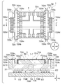
- FIG. 1 is an exploded perspective view schematically showing a configuration of an image pickup apparatus according to an embodiment of the present invention.
- 2 (a) is a plan view schematically showing the configuration of the drive system in FIG. 1, and
- FIG. 2 (b) is a cross-sectional view taken along the line I-I'of FIG. 1 (a).
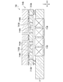
- FIG. 3 is a partially enlarged cross-sectional view of FIG. 2 (b).
- FIG. 4 is a developed view of the flexible wiring body in FIG. 2 (a).
- 5 (a) is a bottom view schematically showing the configuration of the actuator in FIG. 2 (b),
- FIG. 5 (b) is FIG. 5 (b), and
- FIG. 5 (b) is line II-II of FIG. 5 (a).
- FIG. 5 (c) is an enlarged cross-sectional view of the insulating portion in FIG. 5 (b).
- 6 (a) is a plan view showing a modified example of the drive system in FIG. 2 (a)
- FIG. 6 (b) is a cross-sectional view taken along the line III-III'of FIG. 6 (a).
- FIG. 7 is a partially enlarged cross-sectional view of FIG. 6 (b).
- FIG. 8 is a developed view of the flexible wiring body in FIG. 6A.
- FIG. 10 (b) is a partial cross-sectional view of FIG.
- FIG. 11 is a plan view showing another modification of the flexible wiring body in FIG. 12 (a) is a partial plan view showing a state in which the flexible wiring body of FIG. 11 is mounted on the actuator
- FIG. 12 (b) is a partial cross-sectional view of FIG. 12 (a).
- FIG. 13 is a bottom view showing a modified example of the actuator of FIG.
- FIG. 14 is a bottom view showing another modification of the actuator of FIG.
- FIG. 15 is a cross-sectional view showing a modified example of the actuator in FIG. 2 (b).
- the flexible wiring body 73A includes a main portion 731A on which the semiconductor element 6 is mounted and electrically connected to the semiconductor element 6, and a plurality of flexible wiring bodies 73A extending from the main portion 731A toward the frame body 72 and bent three-dimensionally. Has an arm portion of 732A.
- the flexible wiring body 73A has four arm portions 732A, and the four arm portions 732A are referred to, for example, a line along the Y direction through the center of the main portion 731A in a plan view. They are arranged line-symmetrically.
- the arm portion 732A is bent so as to have a main surface 732a intersecting the main surface 731a of the main portion 731A (FIG. 2 (b)), and further folded back and bent (FIG. 2 (a)).
- the deformation gives a degree of freedom to the rotation of the semiconductor element 6 in the horizontal direction (X direction), the vertical direction (Y direction), and the direction perpendicular to the main surface of the semiconductor element 6 (Z direction).
- One end 734Aa of the conductive layer 734A is electrically connected to the semiconductor element 6 via a wire portion 77 such as a bonding wire made of metal, and the other end 734Ab is electrically connected to a connector terminal (not shown).
- the thickness of the resin layer 733A is, for example, 10 ⁇ m to 30 ⁇ m, and the thickness of the conductive layer 734A is, for example, 5 ⁇ m to 15 ⁇ m.
- the resin layer 733A is made of, for example, polyimide (PI), and the conductive layer 734A is made of, for example, copper (Cu).
- the conductive layer is one layer, but it may be multi-layered in order to perform more complicated wiring. Further, an insulating protective film may be formed on the conductive layer. Further, in this figure, only the semiconductor element 6 is mounted on the flexible wiring body 73A, but other elements may be mounted.
- the plurality of arm portions 732A have a conductive layer 734A having 20 or more wires as a whole.
- the arm portion 732A is provided with five conductive layers 734A, and the plurality of arm portions 732A have a total of 20 wires of the conductive layer 734A.
- the conductive layer 734A having 20 or more wires is provided as a whole, there is no limitation on the number of arms and the number of lines or layers of the conductive layer of each arm, and the number can be appropriately changed according to the specifications. .. As a result, it is possible to sufficiently cope with an increase in wiring due to higher functionality of the semiconductor element 6.
- the line width of the 20-line conductive layer 734A is the same in a plan view, but the line width is not limited to this, and the line width of the 20-line conductive layer 734A may be different.
- the plurality of conductive layers 734A may include a narrow conductive layer for communication and a wide conductive layer for electric power.
- a conductive layer through which a high frequency signal for high-speed communication is passed and a conductive layer through which a large current for driving an image pickup element is passed can be provided, and the flexible wiring body 73A can be provided with a high frequency for high-speed communication. It is possible to pass both a signal and a large current for driving an image pickup element.
- the method for forming the flexible wiring body 73A is not particularly limited, and is a subtractive method in which a copper foil of a copper laminated plate is etched to form a circuit, or a semi in which a circuit is formed by electroplating on an insulating base material having a conductive layer. It can be formed by using a method such as an additive method.
- the actuator 71A includes a plurality of base portions 712A fixed to the substrate 8, a movable portion 713A to which the main portion 731A of the flexible wiring body 73A and the semiconductor element 6 are attached via the stage portion 711A, and a base portion 712A and a movable portion 713A. It has a plurality of spring portions 714A to be connected.
- the actuator 71A is not limited in its form as long as it has a base portion 712A, a movable portion 713A, and a plurality of spring portions 714A, but is formed by, for example, MEMS from the viewpoint of miniaturization and ease of manufacture.
- One comb tooth of the comb tooth electrode is formed on the two fixing portions X11 and X12, and the other comb tooth is formed on the first movable portion 713AA described later.
- the four fixed portions GND14, GND14, GND15, and ⁇ 12 are each connected to the first movable portion 713AA described later via the first spring portion 714AA.
- one comb tooth of the comb tooth electrode is formed on each of the two fixing portions X21 and X22, and the other comb tooth is formed on the first movable portion 713AB described later.
- the four fixed portions ⁇ 22, GND23, GND25, and GND23 are each connected to the first movable portion 713AB described later via the first spring portion 714AA.
- the movable portion 713A is arranged in the central portion of the four first movable portions 713AA, 713AB, 713AC, 713AD and the four first movable portions 713AA to 713AD arranged on the four sides (XY directions) of the second movable portion, which will be described later.
- the four first movable portions 713AA to 713AD are connected to each other via a plurality of second spring portions 714AB, and are arranged at the central portion of the second movable portion 713AE and the second movable portion 713AE, which are substantially cross-shaped in a plan view.
- the second movable portion 713AE and the third movable portion 713AF which is connected via a plurality of third spring portions 714AC and has a substantially X shape in a plan view.
- the fixed portions GND14, GND15, GND14, and ⁇ 12 are connected to the first movable portion 713AA via the first spring portion 714AA, respectively.
- the fixed portions ⁇ 22, GND23, GND25, and GND23 are each connected to the first movable portion 713AB via the first spring portion 714AA.
- the fixed portions GND31, GND35, GND31, and ⁇ 31 are each connected to the first movable portion 713AC via the first spring portion 714AA.
- the fixed portions ⁇ 41, GND42, GND45, and GND42 are each connected to the first movable portion 713AD via the first spring portion 714AA.
- the plurality of first spring portions 714AA function as an electrical connection portion in addition to the function as a mechanical connection portion.
- the fixed part X11 has the same potential as the fixed part X21
- the fixed part X12 has the same potential as the fixed part X22
- the fixed portion Y11 has the same potential as the fixed portion Y21
- the fixed portion Y12 has the same potential as the fixed portion Y22.
- the second movable portion 713AE has six moving parts ⁇ 51, ⁇ 52, GND55, ⁇ 61, ⁇ 62, and GND65 provided so as to surround the third movable portion 713AF.
- the moving portions ⁇ 51, ⁇ 52, GND55, ⁇ 61, ⁇ 62, and GND65 are arranged so as to be 180 ° rotationally symmetric with respect to the center of the third movable portion 713AF.
- the symbol "GND" of the moving portion indicates a grounded portion, and the symbol " ⁇ " indicates a portion to which a voltage is applied when rotating in the ⁇ z direction.
- the moving portion ⁇ 51 is connected to the fixed portion ⁇ 31 via the second spring portion 714AB and the first spring portion 714AA.
- the moving portion ⁇ 52 is connected to the fixed portion ⁇ 22 via the second spring portion 714AB and the first spring portion 714AA.
- the moving portion GND55 is connected to the fixing portions GND15 and GND35, respectively, via the second spring portion 714AB and the first spring portion 714AA.
- the moving portion ⁇ 61 is connected to the fixed portion ⁇ 41 via the second spring portion 714AB and the first spring portion 714AA.
- the moving portion ⁇ 62 is connected to the fixed portion ⁇ 12 via the second spring portion 714AB and the first spring portion 714AA.
- the moving portion GND65 is connected to the fixing portions GND25 and GND45 via the second spring portion 714AB and the first spring portion 714AA, respectively. Further, the plurality of second spring portions 714AB and the first spring portion 714AA function not only as a mechanical connection portion but also as an electrical connection portion.
- the third movable portion 713AF is fixed to the stage portion 711A via the adhesive layer 78A (FIG. 2B).
- the third movable portion 713AF moves in one direction in the ⁇ z direction (for example, clockwise), and when the same voltage is applied to the moving portions ⁇ 52 and ⁇ 62, the third movable portion 713AF Moves to the other (eg, counterclockwise) in the ⁇ z direction.
- the first movable portion 713AA to 713AD and the second movable portion 713AE are translated in the X direction and / or the Y direction, and the third movable portion is movable.
- the unit 713AF rotates in the ⁇ z direction. Therefore, the third movable portion 713AF moves in the X direction, the Y direction, and / or the ⁇ z direction.
- the stage portion 711A moves in the X direction, the Y direction and / or the ⁇ z direction as the third movable portion 713AF moves, and the main portion 731A of the flexible wiring body 73A moves in the X direction and Y as the stage portion 711A moves. Move in the direction and / or the ⁇ z direction.
- the plurality of arm portions 732A of the flexible wiring body 73A are easily deformed and follow with the movement of the main portion 731A.
- the method for forming the actuator 71A is not particularly limited, and for example, a substrate such as SOI in which silicon single crystals are formed on both sides of the oxide film is used, and etching such as DRIE (deep-drilling reactive etching) is performed on the handle layer and the active layer. It can be formed by processing. Further, the insulating portion in the actuator 71A can be formed by combining DRIE, LPCVD, polishing and the like.
- the flexible wiring body 73A is directed toward the main portion 731A on which the semiconductor element 6 is mounted and electrically connected to the semiconductor element 6 and the main portion 731A toward the frame body 72. Since it has a plurality of arm portions 732A that are extended and bent three-dimensionally, the main surface 732a of the plurality of arm portions 732A integrally formed with the main portion 731A is not related to the main surface 731a of the main portion 731A.
- the plurality of arm portions 732A are parallel to each other, and the plurality of arm portions 732A are easily and sufficiently bent in the out-of-plane direction with respect to the translation (X direction and / or Y direction) and rotation ( ⁇ z direction) of the main portion 731A fixed to the stage portion 711A.
- the movement of the actuator 71A is less likely to be hindered, and as a result, the positioning performance of the semiconductor element 6 mounted on the main portion 731A can be improved.
- the arm portion 732A with a conductive layer for communication and a conductive layer for electric power, both a high frequency signal for high-speed communication and a large current for driving an image sensor can be stably flowed.
- the flexible wiring body 73A can be formed by subjecting the developed body of the flexible wiring body 73A to a simple bending process, a complicated assembly process is not required and mass production can be supported.
- the plurality of arm portions 732A are arranged symmetrically with respect to the main portion 731A, and the plurality of arm portions 732A are folded back and bent so that the forces due to elastic deformation are balanced. Since it is maintained, even when the actuator 71A is formed of MEMS or the like and the generated force is small, the resistance force due to the rigidity of the flexible wiring body 73A is small, so that the movement of the actuator 71A is not easily hindered. , Highly accurate movement of the semiconductor element 6 can be realized.
- the arm portion 732A has a first portion 732Aa having a main surface 732a substantially perpendicular to the main surface 731a of the main portion 731A, and a second portion provided at one end of the first portion 732Aa and curved by folding back. Since the 732Ab and the third portion 732Ac arranged to face the first portion 732Aa are arranged substantially perpendicular to the main surface 731a of the main portion 731A, the plurality of arm portions 732A are arranged on the stage portion 711A.
- a plurality of insulating portions 715AA to 715AF and 716AA to 716AF are formed in the actuator 71A, and a drive mechanism and circuit for translating in the X direction and a drive mechanism for translating in the Y direction. And the circuit, and the drive mechanism and the circuit for rotating in the ⁇ z direction are provided electrically independently, so that any movement in the X direction, the Y direction, and / or the ⁇ z direction can be realized. Further, since the drive circuit of the actuator 71A is connected to a circuit (not shown) of the substrate 8, the wiring of the actuator 71A and the wiring of the semiconductor element 6 (the conductive layer of the flexible wiring body 73A) are moved up and down with reference to the stage portion 711A.
- FIG. 6 (a) is a plan view showing a modified example of the drive system 7 in FIG. 2 (a), and FIG. 6 (b) is a cross-sectional view taken along the line III-III'of FIG. 6 (a).
- 7 is a partially enlarged cross-sectional view of FIG. 6B.
- the drive system in FIG. 6A mainly does not have the stage portion 711A, and the actuator 71A is directly connected to the flexible wiring body 73A via the adhesive layer 80A. It is different from the configuration of 7.
- the same configurations as those of the drive system 7 in FIG. 2A are designated by the same reference numerals, and the description thereof will be omitted.
- the flexible wiring body 73A of FIG. 6A has the same configuration as the flexible wiring body 73A of FIG. 2A in the deployed state, and is shown in FIG. 2A in a state where a three-dimensional structure is formed by processing. It has a different configuration from the flexible wiring body 73A of.
- the flexible wiring body 73A is defined by a main portion 731A and an arm portion 732A, and has an accommodating portion 81A in which the semiconductor element 6 is accommodated.
- the main portion 731A is fixed to the lower surface 6a of the semiconductor element 6 via the adhesive layer 82A.
- the first portion 732Aa of the arm portion 732A is fixed to the side surface 6b of the semiconductor element 6 via the adhesive layer 83A (FIG. 7). Further, one end 734Aa of the conductive layer 734A is electrically connected to the semiconductor element 6 via a bonding portion 84A formed by ultrasonic connection, thermocompression bonding, connection using a conductive adhesive, or the like, and the other end.
- the 734Ab is electrically connected to a connector terminal (not shown).
- FIG. 8 is a developed view of the flexible wiring body 73A in FIG. 6A.
- the flexible wiring body 73A is mountain-folded along the lines L2 and L2 in FIG. 8, and the intermediate portions of the four arm portions 732A are folded back and bent to form FIGS. 6A and 6 (FIG. 6).
- FIGS. 6A and 6 FIGS. 6A and 6 (FIG. 6).
- a three-dimensional structure as shown in b) is formed.
- the flexible wiring body 73A can be applied to the drive system 7 that does not have the stage portion 711A. That is, the flexible wiring body 73A is bent three-dimensionally by extending from the main portion 731A on which the semiconductor element 6 is placed and electrically connected to the semiconductor element 6 and the main portion 731A toward the frame body 72. Since it has a plurality of arm portions 732A, the main surface 732a of the plurality of arm portions 732A integrally formed with the main portion 731A is non-parallel to the main surface 731a of the main portion 731A, and the plurality of arm portions 732A have a plurality of arm portions 732A.
- the main portion 731A fixed to the stage portion 711A is easily and sufficiently bent in the out-of-plane direction with respect to translation (X direction and / or Y direction) and rotation ( ⁇ z direction), and the movement of the actuator 71A is not easily hindered. As a result, the positioning performance of the semiconductor element 6 mounted on the main portion 731A can be improved. Further, since the semiconductor element 6 and the flexible wiring body 73A are electrically connected by providing the joint portion 84A without providing the wire portion, it contributes to lowering the height of the configuration in which the semiconductor element 6 and the drive system 7 are combined. Can be done.
- FIG. 9 is a plan view showing another modification of the flexible wiring body in FIG. 10 (a) is a partial plan view showing a state in which the flexible wiring body of FIG. 9 is mounted on the actuator, and FIG. 10 (b) is a partial cross-sectional view of FIG. 10 (a).
- the flexible wiring body of FIG. 9 is different from the configuration of the flexible wiring body of FIG. 4 in that the shape of the arm portion is different.
- the flexible wiring body 73B includes a main portion 731B on which the semiconductor element 6 is mounted and electrically connected to the semiconductor element 6, and a frame body 72 from the main portion 731B (FIG. 2A and FIG. It has a plurality of arm portions 732B extending toward (see FIG. 2B) and bent three-dimensionally.
- the arm portion 732B has a first portion 732Ba having a main surface 732c substantially perpendicular to the main surface 731b of the main portion 731B, and a first portion.
- a second portion 732Bb provided at one end of the 732Ba and curved by folding back, a third portion 732Bc arranged to face the first portion 732Ba, and a main surface 731b provided at one end of the third portion 732Bc.
- It has a fourth site 732Ad having a substantially parallel main surface 732d.
- the first portion 732Ba, the second portion 732Bb, and the third portion 732Bc are arranged substantially perpendicular to the main surface 731b of the main portion 731B (FIG. 10 (b)).
- the fourth portion 732Bd has an extension portion 732Bda arranged perpendicularly to the third portion 732Bc and an extension portion 732Bdb arranged perpendicularly to the extension portion 732Bda (FIG. 9).
- the extending portion 732Bda extends in the direction away from the main portion 731B (X direction) in a plan view, and the extending portion 732Bdb extends.
- the two extending portions 732Bdb provided on the two adjacent arm portions 732B extend in the lateral direction (Y direction) and extend in the direction away from each other. Further, in this modification, the fourth portion 732Bd is provided on a plane different from that of the main portion 731B, and is arranged below the main portion 731B.
- the extending portion 732Bdb is provided with the other end portion 734Bb of the conductive layer 734B, the one end portion 734Ba of the conductive layer 734B is electrically connected to the semiconductor element 6, and the other end portion 734Bb is not shown. It is electrically connected to the connector terminal of. Further, in a state where the flexible wiring body 73B is three-dimensionally bent, the other end portion 734Bb of the conductive layer 734B is arranged on the lower side (back side) of the resin layer 733B in the Z direction (FIG. 10 (b)). ..
- the arm portion 732B may have a fifth portion 732Be which becomes a margin portion at the time of bending between the main portion 731B and the first portion 732Ba (FIG. 9). Further, it is preferable that the width direction (Y direction) dimension of the fifth portion 732Be is smaller than the width direction dimension of the main portion 731B. This makes it easier to form the first portion 732Ba by bending, and buckling of the conductive layer 734B at the bent portion can be suppressed, further improving the electrical connection reliability of the conductive layer 734B. can do.
- the fourth portion 732Bd has an extension portion 732Bda arranged perpendicular to the third portion 732Bc and an extension portion 732Bdb arranged perpendicularly to the extension portion 732Bda. Therefore, the degree of freedom in designing the fourth portion 732Bd inserted into the connector terminal can be improved.
- FIG. 11 is a plan view showing another modification of the flexible wiring body in FIG. 12 (a) is a partial plan view showing a state in which the flexible wiring body of FIG. 11 is mounted on the actuator, and FIG. 12 (b) is a partial cross-sectional view of FIG. 12 (a).
- the flexible wiring body 73C includes a main portion 731C on which the semiconductor element 6 is mounted and electrically connected to the semiconductor element 6, and a frame body 72 from the main portion 731C (FIG. 2A and FIG. It has a plurality of arm portions 732C extending toward FIG. 2B) and bent three-dimensionally.
- the arm portion 732C has a first portion 732Ca having a main surface 732e substantially perpendicular to the main surface 731c of the main portion 731C, and a first portion.
- a second portion 732Cb provided at one end of the 732Ca and curved by folding back, a third portion 732Cc arranged opposite to the first portion 732Ca, and a main surface 731c provided at one end of the third portion 732Cc. It has a fourth site 732Cd with a substantially parallel main surface 732f.
- the first portion 732Ca, the second portion 732Cb, and the third portion 732Cc are arranged substantially perpendicular to the main surface 731c of the main portion 731C. (Fig. 10 (b)).
- the fourth portion 732Cd has an extension portion 732Cda arranged perpendicular to the third portion 732Cc and an extension portion 732Cdb arranged perpendicularly to the extension portion 732Cda (FIG. 11).
- the extending portion 732Cda extends in the direction away from the main portion 731C (X direction) in a plan view, and the extending portion 732Cdb is , Extends in the lateral direction (Y direction) from the extension portion 732Cda.
- the two extending portions 732Cdb provided on the two adjacent arm portions 732C extend in the lateral direction (Y direction) and extend in the direction away from each other. Further, in this modification, the fourth portion 732Cd is provided on the same plane as the main portion 731C.
- the extending portion 732Cdb is provided with the other end portion 734Cb of the conductive layer 734C, the one end portion 734Ca of the conductive layer 734C is electrically connected to the semiconductor element 6, and the other end portion 734Bb is formed. It is electrically connected to a connector terminal (not shown). Further, in a state where the flexible wiring body 73C is three-dimensionally bent, the other end portion 734Cb of the conductive layer 734C is arranged on the upper side (front side) of the resin layer 733C in the Z direction (FIG. 12 (b)).
- the fourth portion 732Cd has an extension portion 732Cda arranged perpendicular to the third portion 732Cc and an extension portion 732Cdb arranged perpendicularly to the extension portion 732Cda. Therefore, as with the fourth portion 732Bd of the flexible wiring body 73B, the degree of freedom in designing the fourth portion 732Cd inserted into the connector terminal can be improved.
- FIG. 13 is a bottom view showing a modified example of the actuator 71A of FIG.
- the actuator 71B includes a plurality of base portions 712B fixed to the substrate 8 (see FIG. 2B), and a movable portion 713B to which the main portion 731A of the flexible wiring body 73A and the semiconductor element 6 are attached.
- the actuator 71B is formed by, for example, a MEMS.
- the plurality of bases 712B are fixed portions X31, X32, GND51, GND51 arranged on one end side of the actuator 71B in the X direction, and fixed portions X41, X42, GND51 arranged on the other end side of the actuator 71B in the X direction. It has a GND 51 and.
- the fixing portions X31 and X32 are connected to the substrate 8 via an extraction electrode (not shown) (see FIG. 5B). Since other fixing parts have the same configuration, the description thereof will be omitted.
- One comb tooth of the comb tooth electrode is formed on the two fixing portions X31 and X32, and the other comb tooth is formed on the first movable portion 713BA described later.
- the two fixing portions GND51 and GND51 are connected to the first movable portion 713BA described later via the first spring portion 714BA, respectively.
- one comb tooth of the comb tooth electrode is formed on each of the two fixing portions X41 and X42, and the other comb tooth is formed on the first movable portion 713BB described later.
- the two fixing portions GND51 and GND51 are connected to the first movable portion 713BB, which will be described later, via the first spring portion 714BA, respectively.
- the plurality of base portions 712B have fixed portions Y31, Y32, GND51, and GND51 arranged on one end side of the actuator 71B in the Y direction, and fixed portions Y41 arranged on the other end side of the actuator 71B in the Y direction. , Y42, GND51, GND51.
- One comb tooth of the comb tooth electrode is formed on the two fixing portions Y31 and Y32, and the other comb tooth is formed on the first movable portion 713BC described later.
- the two fixing portions GND51 and GND51 are connected to the first movable portion 713BC described later via the first spring portion 714BA, respectively.
- one comb tooth of the comb tooth electrode is formed on each of the two fixing portions Y41 and Y42, and the other comb tooth is formed on the first movable portion 713BD described later.
- the two fixing portions GND51 and GND51 are connected to the first movable portion 713BD described later via the first spring portion 714BA, respectively.
- the movable portion 713B is arranged in the central portion of the four first movable portions 713BA, 713BB, 713BC, 713BD and the four first movable portions 713BA to 713BD arranged on the four sides (XY directions) of the second movable portion, which will be described later.
- the four first movable portions 713BA to 713BD are connected to each other via a plurality of second spring portions 714BB, and have a substantially windmill-shaped second movable portion 713BE in a plan view.
- the first movable portions 713BA, 713BB, 713BC, and 713BD are, for example, substantially grid-shaped frames in a plan view.
- Fixed portions GND51 and GND51 are arranged on both sides of the first movable portion 713BA in the Y direction, and fixed portions X31 and X32 are arranged inside the first movable portion 713BA.
- the fixed portions GND51 and GND51 are arranged on both sides of the first movable portion 713BB in the Y direction, and the fixed portions X41 and X42 are arranged inside the first movable portion 713BB.
- the fixing portions GND51 and GND51 are arranged on both sides of the first movable portion 713BC in the X direction, and the fixing portions Y31 and Y32 are arranged inside the first movable portion 713BC. Further, the fixing portions GND51 and GND51 are arranged on both sides of the first movable portion 713BD in the X direction, and the fixing portions Y41 and Y42 are arranged inside the first movable portion 713BD.
- the plurality of fixed portions GND51 are connected to the first movable portions 713BA to 713BD via the first spring portion 714BA, respectively. Further, the plurality of first spring portions 714BA function as an electrical connection portion in addition to the function as a mechanical connection portion.
- the first movable parts 713BA, 713BB, 713BC, and 713BD move independently, and the second The movable portion 713BE moves in the X, Y, and ⁇ z directions.
- the first movable portion 713BA and 713BB move equally in the X direction (rightward)
- the second movable portion 713BE moves in the + X direction (rightward).
- the first movable portion 713BA, 713BB, 713BC, and 713BD move equally toward the center, and the second movable portion 713BE moves in the ⁇ z direction (clockwise). Rotate.
- the second movable portion 713BE is connected to four first movable portions 713BA, 713BB, 713BC, and 713BD via eight second spring portions 714BB.
- Two second spring portions 714BB are arranged on one end side of the second movable portion 713BE in the X direction, and two second spring portions 714BB are arranged on the other end side as well.
- two second spring portions 714BB are arranged on one end side of the second movable portion 713BE in the Y direction, and two second spring portions 714BB are arranged on the other end side as well.
- the first movable portions 713BA and 713BB can be moved only in the X direction, and the first movable portions 713BC and 713BD can be moved only in the Y direction.
- the second movable portion 713BE is fixed to the stage portion 711A via the adhesive layer 78A (see FIG. 2B).
- a drive mechanism and a circuit for translating in the X direction and a drive mechanism and a circuit for translating in the Y direction are independently provided, and the above translation and the Y direction in the X direction are provided. Since the rotation in the ⁇ z direction is also controlled by controlling the translation to, the movement of the second movable portion 713BE in the X direction, the Y direction, and / or the ⁇ z direction can be realized.
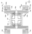
- FIG. 14 is a bottom view showing another modification of the actuator 71A of FIG.
- the actuator 71C includes a plurality of base portions 712C fixed to the substrate 8 (see FIG. 2B), a main portion 731A of the flexible wiring body 73A, and a movable portion 713C to which the semiconductor element 6 is attached.
- the actuator 71C is formed by, for example, a MEMS.
- the plurality of bases 712C are fixed portions X51, X52, GND61, X61, X62, GND61 arranged on one end side of the actuator 71C in the X direction, and fixed portions X71 arranged on the other end side of the actuator 71C in the X direction. It has X72, GND61, X81, X82, and GND61.
- the fixing portions X51 and X52 are connected to the substrate 8 via an extraction electrode (not shown) (see FIG. 5B). Since other fixing parts have the same configuration, the description thereof will be omitted.
- One comb tooth of the comb tooth electrode is formed on the two fixing portions X51 and X52, and the other comb tooth is formed on the first movable portion 713CAA described later.
- one comb tooth of the comb tooth electrode is formed on the two fixing portions X61 and X62, and the other comb tooth is formed on the first movable portion 713CAB described later.
- the two fixing portions GND61 and GND61 are connected to the first movable portion 713CAA and the first movable portion 713CAB, which will be described later, via two first spring portions 714CA, respectively.
- one comb tooth of the comb tooth electrode is formed on the two fixing portions X71 and X72, and the other comb tooth is formed on the first movable portion 713CBA described later.
- one comb tooth of the comb tooth electrode is formed on the two fixing portions X81 and X82, and the other comb tooth is formed on the first movable portion 713CBB described later.
- the two fixing portions GND61 and GND61 are connected to the first movable portion 713CBA and the first movable portion 713CBB, which will be described later, via two first spring portions 714CA, respectively.
- the plurality of bases 712C are fixed portions Y51, Y52, GND61, Y61, Y62, GND61 arranged on one end side of the actuator 71C in the Y direction, and fixed portions arranged on the other end side of the actuator 71C in the Y direction. It has Y71, Y72, GND61, Y81, Y82, and GND61.
- One comb tooth of the comb tooth electrode is formed on the two fixing portions Y51 and Y52, and the other comb tooth is formed on the first movable portion 713CCA described later.
- one comb tooth of the comb tooth electrode is formed on the two fixing portions Y61 and Y62, and the other comb tooth is formed on the first movable portion 713CCB described later.
- the two fixing portions GND61 and GND61 are connected to the first movable portion 713CCA and the first movable portion 713CCB, which will be described later, via two first spring portions 714CA, respectively.
- one comb tooth of the comb tooth electrode is formed on the two fixing portions Y71 and Y72, and the other comb tooth is formed on the first movable portion 713CDA described later.
- one comb tooth of the comb tooth electrode is formed on the two fixing portions Y81 and Y82, and the other comb tooth is formed on the first movable portion 713CDB described later.
- the two fixing portions GND61 and GND61 are connected to the first movable portion 713CDA and the first movable portion 713CDB, which will be described later, via two first spring portions 714CA, respectively.
- the movable portion 713C includes eight first movable portions 713CAA, 713CAB, 713CBA, 713CBB, 713CCA, 713CCB, 713CDA, and 713CDB arranged on four sides (XY directions) of the second movable portion, which will be described later, and eight first movable portions. It is arranged in the central portion of 713CAA to 713CDB, is connected to eight first movable portions 713CAA to 713CDB via a plurality of second spring portions 714CB, and has a second movable portion 713CE which is substantially rectangular in a plan view.
- the first movable portions 713CAA, 713CAB, 713CBA, 713CBB, 713CCA, 713CCB, 713CDA, and 713CDB are, for example, substantially rectangular frames in a plan view.
- the fixed portion X51 is arranged on the side of the first movable portion 713CAA opposite to the second movable portion 713CE in the X direction, and the fixed portions X52 and GND61 are arranged inside the first movable portion 713CAA.
- the fixed portion X61 is arranged on the side of the first movable portion 713CAB opposite to the second movable portion 713CE in the X direction, and the fixed portions X52 and GND61 are arranged inside the first movable portion 713CAB.
- the fixed portion X71 is arranged on the side of the first movable portion 713CBA opposite to the second movable portion 713CE in the X direction, and the fixed portions X72 and GND61 are arranged inside the first movable portion 713CBA.
- the fixed portion X81 is arranged on the side of the first movable portion 713CBB opposite to the second movable portion 713CE in the X direction, and the fixed portions X82 and GND61 are arranged inside the first movable portion 713CBB.
- the fixed portion Y52 is arranged on the side of the first movable portion 713CCA opposite to the second movable portion 713CE in the Y direction, and the fixed portions Y51 and GND61 are arranged inside the first movable portion 713CCA. .. Further, the fixed portion X62 is arranged on the side of the first movable portion 713CCB opposite to the second movable portion 713CE in the Y direction, and the fixed portions Y61 and GND61 are arranged inside the first movable portion 713CCB.
- the fixed portion Y72 is arranged on the side of the first movable portion 713CDA opposite to the second movable portion 713CE in the Y direction, and the fixed portions Y71 and GND61 are arranged inside the first movable portion 713CDA.
- the fixed portion Y82 is arranged on the side of the first movable portion 713CDB opposite to the second movable portion 713CE in the Y direction, and the fixed portions Y81 and GND61 are arranged inside the first movable portion 713CDB.
- the plurality of fixed portions GND61 are connected to the first movable portion 713CAA to 713CDB via the first spring portion 714CA, respectively. Further, the plurality of first spring portions 714CA function as an electrical connection portion in addition to the function as a mechanical connection portion.
- the first movable portions 713CAA, 713CAB, 713CBA, and 713CBB move in one of the X directions (for example, the + X direction), and the fixed portions X51 and X61.
- the first movable portions 713CAA, 713CAB, 713CBA and 713CBB move in the other direction in the X direction (for example, in the ⁇ X direction).
- the first movable portions 713BC and 713BD move in one of the Y directions (for example, the + Y direction), and the voltage is applied to the fixed portions Y51, Y61, Y72, and Y82.
- the first movable portions 713BC and 713BD move in the other direction in the Y direction (for example, in the ⁇ Y direction).
- the second movable portion 713CE is connected to eight first movable portions 713CAA, 713CAB, 713CBA, 713CBB, 713CCA, 713CCB, 713CDA, and 713CDB via eight second spring portions 714CB.
- Two second spring portions 714CB are arranged on one end side of the second movable portion 713CE in the X direction, and two second spring portions 714CB are arranged on the other end side as well. Further, two second spring portions 714CB are arranged on one end side of the second movable portion 713BE in the Y direction, and two second spring portions 714CB are arranged on the other end side as well.
- the second movable portion 713CE is fixed to the stage portion 711A via the adhesive layer 78A (see FIG. 2B).
- the second movable portion 713CE has the same potential as the fixed portion GND61.
- the first movable part 713CAA, 713CAB, 713CBA, 713CBB moves in one direction in the X direction (for example, + X direction), and the first movable part 713CCA, 713CCB, 713CDA, 713CDB moves in one direction in the Y direction (for example, + X direction). For example, move in the + Y direction).
- the second movable portion 713CE moves in the X, Y, and ⁇ z directions.
- the first movable portion 713CAA, 713CAB, 713CBA, and 713CBB move equally in the + X direction (rightward), and the second movable portion 713CE moves in the + X direction (rightward).
- the same voltage is applied to the fixed portions X52, X61, X71, X82, Y52, Y61, Y71, Y82, the first movable parts 713CAA and 713CBA are in the + X direction, and the first movable parts 713CAB and 713CBB are in the -X direction.
- the first movable part 713CCA and 713CDA move in the + Y direction (upward)
- the first movable part 713CBB and 713CDB move in the ⁇ Y direction
- the second movable part 713CE moves in the ⁇ z direction (clockwise).
- the first movable portion 713CAA to 713CDB are translated in the X direction and / or the Y direction, and the second movable portion 713BE is X, Y. , Moves in the ⁇ z direction.
- a drive mechanism and a circuit for translating in the X direction and a drive mechanism and a circuit for translating in the Y direction are independently provided, and the above translation and the Y direction in the X direction are provided. Since the rotation in the ⁇ z direction is performed by controlling the translation to, the movement of the second movable portion 713CE in the X direction, the Y direction, and / or the ⁇ z direction can be realized.
- FIG. 15 is a cross-sectional view showing a modified example of the actuator 71A of FIG. 2 (b). This modification differs from the actuator 71A in that the actuator is an electromagnetic actuator.
- the actuator 71D has a MEMS 711D mounted on the substrate 8 and a plurality of coils 712D provided in the substrate 8 and electrically connected to an external circuit (not shown).
- the MEMS 711D includes a base portion 711DA supported by the substrate 8, a movable portion 711DB fixed to the main portion 731A of the flexible wiring body 73A and the semiconductor element 6, and a plurality of spring portions 711DC connecting the base portion 711DA and the movable portion 711DB.
- the plurality of coils 712D are arranged at positions directly below the MEMS 711D and corresponding to the plurality of magnetic bodies 711DD, and are embedded in a substrate 8 such as a printed circuit board or a ceramic substrate. Since the configurations of the base 711DA, the movable portion 711DB, and the plurality of spring portions 711DC of the MEMS 711D are basically the same as the configurations of the base portion, the movable portion, and the plurality of spring portions of the actuator described above, the description thereof will be omitted.
- the magnetic body 711DD is formed by using a magnetic powder such as a neodymium magnet, and is embedded in the movable portion 711DB.
- the magnetic material 711DD can be obtained by forming a hole in a substrate such as SOI by DRIE and fixing the magnetic powder to the hole by film formation with the magnetic powder inside the hole.
- the magnetic powders are bonded to each other by a film-forming body, and the film-forming body is composed of, for example, alumina (Al 2 O 3 ) and is formed of ALD.
- the magnetic powders are bonded together by a resin binder.
- a magnetic material for example, CoPt
- the thickness of the magnetic material 711DD can be increased with respect to the thickness of the substrate such as SOI, and the magnetic material 711DD having a high magnetic force can be formed on the movable portion 711DB.
- the actuator 71D may have at least one displacement sensor that measures the displacement of at least one of the movable portion 711DB and the plurality of spring portions 711DC.
- a displacement sensor and its circuit can be formed on the MEMS711D.
- the movable portion 711DB can be moved in the X direction, the Y direction, and / or the ⁇ z direction by using the actuator 71D which is an electromagnetic actuator, and the semiconductor element 6 has high accuracy like the electrostatic actuator. Movement can be realized.
- the actuator 71A translates in the X and Y directions among the XYZ directions orthogonal to each other, and rotates around the axis in the Z direction ( ⁇ z direction), but the present invention is not limited to this.
- At least one of the rotational movements (in the ⁇ z direction) may be performed.
Landscapes
- Engineering & Computer Science (AREA)
- Signal Processing (AREA)
- Microelectronics & Electronic Packaging (AREA)
- Multimedia (AREA)
- Physics & Mathematics (AREA)
- Electromagnetism (AREA)
- Combustion & Propulsion (AREA)
- Power Engineering (AREA)
- Chemical & Material Sciences (AREA)
- General Physics & Mathematics (AREA)
- Micromachines (AREA)
- Studio Devices (AREA)
- Adjustment Of Camera Lenses (AREA)
- Structure Of Printed Boards (AREA)
- Reciprocating, Oscillating Or Vibrating Motors (AREA)
Priority Applications (3)
| Application Number | Priority Date | Filing Date | Title |
|---|---|---|---|
| US17/798,866 US20230156911A1 (en) | 2020-02-10 | 2021-02-09 | Flexible wiring body, driving system, and imaging device |
| CN202180026741.5A CN115461677A (zh) | 2020-02-10 | 2021-02-09 | 柔性布线体、驱动系统以及摄像装置 |
| JP2022500412A JP7643738B2 (ja) | 2020-02-10 | 2021-02-09 | フレキシブル配線体、駆動システムおよび撮像装置 |
Applications Claiming Priority (2)
| Application Number | Priority Date | Filing Date | Title |
|---|---|---|---|
| JP2020-021006 | 2020-02-10 | ||
| JP2020021006A JP2020106845A (ja) | 2020-02-10 | 2020-02-10 | フレキシブル配線体、駆動システムおよび撮像装置 |
Publications (1)
| Publication Number | Publication Date |
|---|---|
| WO2021161976A1 true WO2021161976A1 (ja) | 2021-08-19 |
Family
ID=71450821
Family Applications (1)
| Application Number | Title | Priority Date | Filing Date |
|---|---|---|---|
| PCT/JP2021/004696 Ceased WO2021161976A1 (ja) | 2020-02-10 | 2021-02-09 | フレキシブル配線体、駆動システムおよび撮像装置 |
Country Status (4)
| Country | Link |
|---|---|
| US (1) | US20230156911A1 (https=) |
| JP (2) | JP2020106845A (https=) |
| CN (1) | CN115461677A (https=) |
| WO (1) | WO2021161976A1 (https=) |
Cited By (2)
| Publication number | Priority date | Publication date | Assignee | Title |
|---|---|---|---|---|
| EP4307697A1 (en) * | 2022-07-12 | 2024-01-17 | Largan Precision Co. Ltd. | Camera module and electronic device |
| EP4319177A1 (en) * | 2022-08-03 | 2024-02-07 | Largan Precision Co. Ltd. | Shiftable image sensor module, camera module and electronic device |
Families Citing this family (7)
| Publication number | Priority date | Publication date | Assignee | Title |
|---|---|---|---|---|
| CN112492165B (zh) * | 2020-11-30 | 2022-03-15 | 维沃移动通信有限公司 | 摄像头模组、成像方法和电子设备 |
| US12389704B1 (en) * | 2021-01-15 | 2025-08-12 | Apple Inc. | Image sensor package for camera with sensor shift actuation |
| EP4300986A1 (en) * | 2022-06-30 | 2024-01-03 | Largan Precision Co. Ltd. | Shiftable circuit element, shiftable image sensor module, camera module and electronic device |
| CN120130075A (zh) * | 2022-09-02 | 2025-06-10 | Lg伊诺特有限公司 | 相机装置和光学仪器 |
| US12231753B1 (en) * | 2022-09-07 | 2025-02-18 | Apple Inc. | Flexure arm separator for flexure module of camera with moveable image sensor |
| WO2025015292A2 (en) * | 2023-07-12 | 2025-01-16 | MEMS Drive (Nanjing) Co., Ltd. | Electromagnetic mems assembly |
| DE102023211945A1 (de) * | 2023-11-29 | 2025-06-05 | Robert Bosch Gesellschaft mit beschränkter Haftung | Mikroelektromechanische Haltevorrichtung, Bildsensorvorrichtung und Verfahren zum Herstellen einer mikroelektromechanischen Haltevorrichtung |
Citations (5)
| Publication number | Priority date | Publication date | Assignee | Title |
|---|---|---|---|---|
| JP2008203402A (ja) * | 2007-02-19 | 2008-09-04 | Konica Minolta Opto Inc | センサ装置、および撮像装置 |
| JP2009128521A (ja) * | 2007-11-21 | 2009-06-11 | Fujifilm Corp | フレキシブル配線板及び撮像装置 |
| JP2012521566A (ja) * | 2009-03-18 | 2012-09-13 | バイヤー・マテリアルサイエンス・アーゲー | ウエハレベル光学システム |
| JP2013072967A (ja) * | 2011-09-27 | 2013-04-22 | Toshiba Corp | 手振れ補正装置及び撮像装置 |
| US20160241785A1 (en) * | 2015-02-13 | 2016-08-18 | Ue Technology Co., Ltd. | Optical Image Stabilizing Device |
Family Cites Families (6)
| Publication number | Priority date | Publication date | Assignee | Title |
|---|---|---|---|---|
| JP4958869B2 (ja) * | 2008-09-30 | 2012-06-20 | 日本電産コパル株式会社 | 像振れ補正装置、撮像レンズユニット、及びカメラユニット |
| US20160241787A1 (en) * | 2013-09-27 | 2016-08-18 | Sharp Kabushiki Kaisha | Camera module |
| CN107615160B (zh) * | 2015-05-29 | 2020-06-16 | 三美电机株式会社 | 致动器、摄像机模块及摄像机搭载装置 |
| CN119781132A (zh) * | 2016-03-11 | 2025-04-08 | 苹果公司 | 具有用于移动图像传感器的音圈电机的光学图像稳定 |
| JP6993567B2 (ja) * | 2017-09-29 | 2022-02-03 | ミツミ電機株式会社 | レンズ駆動装置、カメラモジュール、およびカメラ搭載装置 |
| CN111656240B (zh) * | 2018-01-24 | 2022-06-10 | 麦斯卓有限公司 | Mems致动系统 |
-
2020
- 2020-02-10 JP JP2020021006A patent/JP2020106845A/ja active Pending
-
2021
- 2021-02-09 JP JP2022500412A patent/JP7643738B2/ja active Active
- 2021-02-09 WO PCT/JP2021/004696 patent/WO2021161976A1/ja not_active Ceased
- 2021-02-09 CN CN202180026741.5A patent/CN115461677A/zh active Pending
- 2021-02-09 US US17/798,866 patent/US20230156911A1/en not_active Abandoned
Patent Citations (5)
| Publication number | Priority date | Publication date | Assignee | Title |
|---|---|---|---|---|
| JP2008203402A (ja) * | 2007-02-19 | 2008-09-04 | Konica Minolta Opto Inc | センサ装置、および撮像装置 |
| JP2009128521A (ja) * | 2007-11-21 | 2009-06-11 | Fujifilm Corp | フレキシブル配線板及び撮像装置 |
| JP2012521566A (ja) * | 2009-03-18 | 2012-09-13 | バイヤー・マテリアルサイエンス・アーゲー | ウエハレベル光学システム |
| JP2013072967A (ja) * | 2011-09-27 | 2013-04-22 | Toshiba Corp | 手振れ補正装置及び撮像装置 |
| US20160241785A1 (en) * | 2015-02-13 | 2016-08-18 | Ue Technology Co., Ltd. | Optical Image Stabilizing Device |
Cited By (4)
| Publication number | Priority date | Publication date | Assignee | Title |
|---|---|---|---|---|
| EP4307697A1 (en) * | 2022-07-12 | 2024-01-17 | Largan Precision Co. Ltd. | Camera module and electronic device |
| US12556792B2 (en) | 2022-07-12 | 2026-02-17 | Largan Precision Co., Ltd. | Camera module and electronic device |
| EP4319177A1 (en) * | 2022-08-03 | 2024-02-07 | Largan Precision Co. Ltd. | Shiftable image sensor module, camera module and electronic device |
| US12464241B2 (en) | 2022-08-03 | 2025-11-04 | Largan Precision Co., Ltd. | Shiftable image sensor module, camera module and electronic device |
Also Published As
| Publication number | Publication date |
|---|---|
| JPWO2021161976A1 (https=) | 2021-08-19 |
| JP7643738B2 (ja) | 2025-03-11 |
| CN115461677A (zh) | 2022-12-09 |
| US20230156911A1 (en) | 2023-05-18 |
| JP2020106845A (ja) | 2020-07-09 |
Similar Documents
| Publication | Publication Date | Title |
|---|---|---|
| JP7643738B2 (ja) | フレキシブル配線体、駆動システムおよび撮像装置 | |
| US11425295B2 (en) | Integrated substrate for anti-shake apparatus | |
| CN108602663B (zh) | Mems致动器组结构 | |
| CN111295513B (zh) | 形状记忆合金致动器支承部 | |
| CN102906638B (zh) | 具有mems执行器的相机模块 | |
| US20180259740A1 (en) | Lens actuator | |
| WO2018018998A1 (zh) | 成像方法、成像装置及电子装置 | |
| JP2009216878A (ja) | レンズ駆動装置およびカメラモジュール | |
| TW202544522A (zh) | 光學元件驅動機構 | |
| JP2018041085A (ja) | 光の二次元偏向のためのマイクロメカニカル装置及び方法 | |
| CN113068362B (zh) | 一种柔性电路板组件、驱动装置、摄像模组及电子产品 | |
| CN113825905B (zh) | 致动器组件 | |
| KR20110127922A (ko) | 멤스 액추에이터를 포함하는 카메라 모듈 | |
| CN106132867A (zh) | 用于移动光电设备的致动器 | |
| CN113556446A (zh) | 具有防抖功能的感光组件及相应摄像模组 | |
| CN116888969A (zh) | 传感器驱动装置 | |
| CN107277306B (zh) | 摄像模块 | |
| US20260122331A1 (en) | Camera device and optical instrument | |
| CN113014785A (zh) | 一种柔性电路板组件、驱动装置、摄像模组及电子产品 | |
| CN115442499B (zh) | 摄像模组 | |
| CN116437210A (zh) | 传感器移位致动器及包括传感器移位致动器的相机模块 | |
| JP7175603B2 (ja) | アクチュエータ、レンズ駆動モータ及び電子機器 | |
| CN115706855A (zh) | 弹性连接组件、光学防抖装置、及其电子设备 | |
| CN204887703U (zh) | 一种用于焊接图像传感器的柔性电路板 | |
| JP2018173581A (ja) | モバイル用電磁駆動装置 |
Legal Events
| Date | Code | Title | Description |
|---|---|---|---|
| 121 | Ep: the epo has been informed by wipo that ep was designated in this application |
Ref document number: 21754301 Country of ref document: EP Kind code of ref document: A1 |
|
| ENP | Entry into the national phase |
Ref document number: 2022500412 Country of ref document: JP Kind code of ref document: A |
|
| NENP | Non-entry into the national phase |
Ref country code: DE |
|
| 122 | Ep: pct application non-entry in european phase |
Ref document number: 21754301 Country of ref document: EP Kind code of ref document: A1 |