WO2021161815A1 - 接着フィルム製造装置及びリール体 - Google Patents
接着フィルム製造装置及びリール体 Download PDFInfo
- Publication number
- WO2021161815A1 WO2021161815A1 PCT/JP2021/003318 JP2021003318W WO2021161815A1 WO 2021161815 A1 WO2021161815 A1 WO 2021161815A1 JP 2021003318 W JP2021003318 W JP 2021003318W WO 2021161815 A1 WO2021161815 A1 WO 2021161815A1
- Authority
- WO
- WIPO (PCT)
- Prior art keywords
- adhesive film
- adhesive
- base material
- winding core
- adhesive layer
- Prior art date
- Legal status (The legal status is an assumption and is not a legal conclusion. Google has not performed a legal analysis and makes no representation as to the accuracy of the status listed.)
- Ceased
Links
Images



Classifications
-
- B—PERFORMING OPERATIONS; TRANSPORTING
- B65—CONVEYING; PACKING; STORING; HANDLING THIN OR FILAMENTARY MATERIAL
- B65H—HANDLING THIN OR FILAMENTARY MATERIAL, e.g. SHEETS, WEBS, CABLES
- B65H18/00—Winding webs
- B65H18/08—Web-winding mechanisms
-
- B—PERFORMING OPERATIONS; TRANSPORTING
- B65—CONVEYING; PACKING; STORING; HANDLING THIN OR FILAMENTARY MATERIAL
- B65H—HANDLING THIN OR FILAMENTARY MATERIAL, e.g. SHEETS, WEBS, CABLES
- B65H18/00—Winding webs
- B65H18/08—Web-winding mechanisms
- B65H18/10—Mechanisms in which power is applied to web-roll spindle
- B65H18/103—Reel-to-reel type web winding and unwinding mechanisms
-
- B—PERFORMING OPERATIONS; TRANSPORTING
- B65—CONVEYING; PACKING; STORING; HANDLING THIN OR FILAMENTARY MATERIAL
- B65H—HANDLING THIN OR FILAMENTARY MATERIAL, e.g. SHEETS, WEBS, CABLES
- B65H18/00—Winding webs
- B65H18/08—Web-winding mechanisms
- B65H18/10—Mechanisms in which power is applied to web-roll spindle
-
- B—PERFORMING OPERATIONS; TRANSPORTING
- B65—CONVEYING; PACKING; STORING; HANDLING THIN OR FILAMENTARY MATERIAL
- B65H—HANDLING THIN OR FILAMENTARY MATERIAL, e.g. SHEETS, WEBS, CABLES
- B65H18/00—Winding webs
- B65H18/02—Supporting web roll
- B65H18/021—Multiple web roll supports
-
- B—PERFORMING OPERATIONS; TRANSPORTING
- B65—CONVEYING; PACKING; STORING; HANDLING THIN OR FILAMENTARY MATERIAL
- B65H—HANDLING THIN OR FILAMENTARY MATERIAL, e.g. SHEETS, WEBS, CABLES
- B65H35/00—Delivering articles from cutting or line-perforating machines; Article or web delivery apparatus incorporating cutting or line-perforating devices, e.g. adhesive tape dispensers
- B65H35/02—Delivering articles from cutting or line-perforating machines; Article or web delivery apparatus incorporating cutting or line-perforating devices, e.g. adhesive tape dispensers from or with longitudinal slitters or perforators
-
- B—PERFORMING OPERATIONS; TRANSPORTING
- B65—CONVEYING; PACKING; STORING; HANDLING THIN OR FILAMENTARY MATERIAL
- B65H—HANDLING THIN OR FILAMENTARY MATERIAL, e.g. SHEETS, WEBS, CABLES
- B65H75/00—Storing webs, tapes, or filamentary material, e.g. on reels
- B65H75/02—Cores, formers, supports, or holders for coiled, wound, or folded material, e.g. reels, spindles, bobbins, cop tubes, cans, mandrels or chucks
- B65H75/04—Kinds or types
- B65H75/08—Kinds or types of circular or polygonal cross-section
- B65H75/10—Kinds or types of circular or polygonal cross-section without flanges, e.g. cop tubes
-
- B—PERFORMING OPERATIONS; TRANSPORTING
- B65—CONVEYING; PACKING; STORING; HANDLING THIN OR FILAMENTARY MATERIAL
- B65H—HANDLING THIN OR FILAMENTARY MATERIAL, e.g. SHEETS, WEBS, CABLES
- B65H75/00—Storing webs, tapes, or filamentary material, e.g. on reels
- B65H75/02—Cores, formers, supports, or holders for coiled, wound, or folded material, e.g. reels, spindles, bobbins, cop tubes, cans, mandrels or chucks
- B65H75/18—Constructional details
-
- C—CHEMISTRY; METALLURGY
- C09—DYES; PAINTS; POLISHES; NATURAL RESINS; ADHESIVES; COMPOSITIONS NOT OTHERWISE PROVIDED FOR; APPLICATIONS OF MATERIALS NOT OTHERWISE PROVIDED FOR
- C09J—ADHESIVES; NON-MECHANICAL ASPECTS OF ADHESIVE PROCESSES IN GENERAL; ADHESIVE PROCESSES NOT PROVIDED FOR ELSEWHERE; USE OF MATERIALS AS ADHESIVES
- C09J7/00—Adhesives in the form of films or foils
- C09J7/20—Adhesives in the form of films or foils characterised by their carriers
-
- C—CHEMISTRY; METALLURGY
- C09—DYES; PAINTS; POLISHES; NATURAL RESINS; ADHESIVES; COMPOSITIONS NOT OTHERWISE PROVIDED FOR; APPLICATIONS OF MATERIALS NOT OTHERWISE PROVIDED FOR
- C09J—ADHESIVES; NON-MECHANICAL ASPECTS OF ADHESIVE PROCESSES IN GENERAL; ADHESIVE PROCESSES NOT PROVIDED FOR ELSEWHERE; USE OF MATERIALS AS ADHESIVES
- C09J7/00—Adhesives in the form of films or foils
- C09J7/30—Adhesives in the form of films or foils characterised by the adhesive composition
-
- B—PERFORMING OPERATIONS; TRANSPORTING
- B65—CONVEYING; PACKING; STORING; HANDLING THIN OR FILAMENTARY MATERIAL
- B65H—HANDLING THIN OR FILAMENTARY MATERIAL, e.g. SHEETS, WEBS, CABLES
- B65H2301/00—Handling processes for sheets or webs
- B65H2301/40—Type of handling process
- B65H2301/41—Winding, unwinding
- B65H2301/413—Supporting web roll
- B65H2301/4139—Supporting means for several rolls
- B65H2301/41398—Supporting means for several rolls juxtaposed
-
- B—PERFORMING OPERATIONS; TRANSPORTING
- B65—CONVEYING; PACKING; STORING; HANDLING THIN OR FILAMENTARY MATERIAL
- B65H—HANDLING THIN OR FILAMENTARY MATERIAL, e.g. SHEETS, WEBS, CABLES
- B65H2301/00—Handling processes for sheets or webs
- B65H2301/40—Type of handling process
- B65H2301/41—Winding, unwinding
- B65H2301/414—Winding
- B65H2301/4148—Winding slitting
-
- B—PERFORMING OPERATIONS; TRANSPORTING
- B65—CONVEYING; PACKING; STORING; HANDLING THIN OR FILAMENTARY MATERIAL
- B65H—HANDLING THIN OR FILAMENTARY MATERIAL, e.g. SHEETS, WEBS, CABLES
- B65H2301/00—Handling processes for sheets or webs
- B65H2301/40—Type of handling process
- B65H2301/41—Winding, unwinding
- B65H2301/414—Winding
- B65H2301/4148—Winding slitting
- B65H2301/41486—Winding slitting winding on two or more winding shafts simultaneously
-
- B—PERFORMING OPERATIONS; TRANSPORTING
- B65—CONVEYING; PACKING; STORING; HANDLING THIN OR FILAMENTARY MATERIAL
- B65H—HANDLING THIN OR FILAMENTARY MATERIAL, e.g. SHEETS, WEBS, CABLES
- B65H2511/00—Dimensions; Position; Numbers; Identification; Occurrences
- B65H2511/10—Size; Dimensions
- B65H2511/12—Width
-
- B—PERFORMING OPERATIONS; TRANSPORTING
- B65—CONVEYING; PACKING; STORING; HANDLING THIN OR FILAMENTARY MATERIAL
- B65H—HANDLING THIN OR FILAMENTARY MATERIAL, e.g. SHEETS, WEBS, CABLES
- B65H2511/00—Dimensions; Position; Numbers; Identification; Occurrences
- B65H2511/10—Size; Dimensions
- B65H2511/18—Size; Dimensions relative to handling machine
-
- B—PERFORMING OPERATIONS; TRANSPORTING
- B65—CONVEYING; PACKING; STORING; HANDLING THIN OR FILAMENTARY MATERIAL
- B65H—HANDLING THIN OR FILAMENTARY MATERIAL, e.g. SHEETS, WEBS, CABLES
- B65H2701/00—Handled material; Storage means
- B65H2701/10—Handled articles or webs
- B65H2701/11—Dimensional aspect of article or web
- B65H2701/113—Size
- B65H2701/1133—Size of webs
- B65H2701/11332—Size of webs strip, tape, narrow web
-
- B—PERFORMING OPERATIONS; TRANSPORTING
- B65—CONVEYING; PACKING; STORING; HANDLING THIN OR FILAMENTARY MATERIAL
- B65H—HANDLING THIN OR FILAMENTARY MATERIAL, e.g. SHEETS, WEBS, CABLES
- B65H2701/00—Handled material; Storage means
- B65H2701/10—Handled articles or webs
- B65H2701/17—Nature of material
- B65H2701/172—Composite material
- B65H2701/1722—Composite material including layer with adhesive properties
-
- B—PERFORMING OPERATIONS; TRANSPORTING
- B65—CONVEYING; PACKING; STORING; HANDLING THIN OR FILAMENTARY MATERIAL
- B65H—HANDLING THIN OR FILAMENTARY MATERIAL, e.g. SHEETS, WEBS, CABLES
- B65H2701/00—Handled material; Storage means
- B65H2701/30—Handled filamentary material
- B65H2701/37—Tapes
- B65H2701/377—Adhesive tape
-
- C—CHEMISTRY; METALLURGY
- C09—DYES; PAINTS; POLISHES; NATURAL RESINS; ADHESIVES; COMPOSITIONS NOT OTHERWISE PROVIDED FOR; APPLICATIONS OF MATERIALS NOT OTHERWISE PROVIDED FOR
- C09J—ADHESIVES; NON-MECHANICAL ASPECTS OF ADHESIVE PROCESSES IN GENERAL; ADHESIVE PROCESSES NOT PROVIDED FOR ELSEWHERE; USE OF MATERIALS AS ADHESIVES
- C09J2301/00—Additional features of adhesives in the form of films or foils
- C09J2301/10—Additional features of adhesives in the form of films or foils characterized by the structural features of the adhesive tape or sheet
- C09J2301/16—Additional features of adhesives in the form of films or foils characterized by the structural features of the adhesive tape or sheet by the structure of the carrier layer
Definitions
- This disclosure relates to an adhesive film manufacturing apparatus and a reel body.
- a conventional semiconductor package includes a semiconductor element bonded on a die pad and a lead frame bonded to the semiconductor element with a wire, and has a structure in which the entire structure is sealed with resin except for an outer lead for external connection.
- a QFN Quad Flat Non-leaded
- the lead frame does not protrude from the sealing resin, so that the area and thickness of the package can be reduced.
- the sealing resin wraps around the back surface of the lead frame.
- Patent Document 1 there is a method of attaching an adhesive film as a temporary protective film to the back surface of the lead frame. In this method, the semiconductor element is sealed with the back surface of the lead frame temporarily protected by the adhesive film, and then the adhesive film is peeled off from the back surface of the lead frame.
- the adhesive film used as a temporary protective film is formed, for example, by cutting out a base material fed from a feeding roller to an arbitrary width.
- the cut-out adhesive film of each width is wound up by the winding core and treated as a reel body.
- the adhesive film is pulled out from the reel body and the adhesive film is attached to the back surface of the lead frame.
- the present disclosure has been made to solve the above problems, and an object of the present invention is to provide an adhesive film manufacturing apparatus and a reel body capable of winding up adhesive films having different widths and reducing the manufacturing cost of the reel body. And.
- the adhesive film manufacturing apparatus is an adhesive film manufacturing apparatus for producing an adhesive film having an adhesive layer on a base material layer, and is a feeding roller for feeding out a base material of the adhesive film and a mother of the adhesive film. It is provided with a cutting portion for cutting the material into a plurality of adhesive films having a predetermined width, and a plurality of cores for winding each of the plurality of adhesive films, and each of the plurality of cores is wider than the width of the adhesive film to be wound. Also has a large width.
- each of the plurality of winding cores for winding the adhesive film has a width larger than the width of the adhesive film to be wound.
- the adhesive film having a width smaller than that of the core can be wound by using the core having the same width. Therefore, in this adhesive film manufacturing apparatus, it is possible to reduce the types of winding cores to be prepared, and it is possible to reduce the manufacturing cost of the reel body.
- the protruding portion of the winding core can be used to align the adhesive film when using the adhesive film wound around the winding core. It will be easy.
- Each of the plurality of winding cores may be arranged so that the edge portion of the winding core protrudes from the adhesive film to be wound only on one side in the axial direction. In this case, when the adhesive film wound around the winding core is used, the alignment of the adhesive film becomes easier.
- the reel body according to one aspect of the present disclosure is a reel body formed by winding an adhesive film having an adhesive layer on a base material layer around a winding core, and the winding core has a width larger than the width of the adhesive film. doing.
- the width of the winding core is larger than the width of the adhesive film.
- the adhesive film having a width smaller than that of the core can be wound by using the core having the same width. Therefore, in this reel body, it is possible to reduce the types of winding cores to be prepared, and it is possible to reduce the manufacturing cost.
- the protruding portion of the winding core can be used to align the adhesive film when using the adhesive film wound around the winding core. It will be easy.
- the edge of the winding core may protrude from the winding body of the adhesive film only on one side in the axial direction. In this case, when the adhesive film wound around the winding core is used, the alignment of the adhesive film becomes easier.
- the edge of the winding core protrudes from the side surface of the wound body of the adhesive film to both sides in the axial direction, and the amount of protrusion of one in the axial direction may be larger than the amount of protrusion of the other. In this case, when the adhesive film wound around the winding core is used, the alignment of the adhesive film becomes easier.
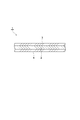
- FIG. 5 is a schematic cross-sectional view showing another embodiment of the adhesive film.
- FIG. 5 is a schematic cross-sectional view showing another embodiment of the adhesive film.
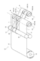
- It is a schematic perspective view which shows one Embodiment of the adhesive film manufacturing apparatus.
- It is a schematic cross-sectional view which shows the winding state of the base material of the adhesive film in the feeding roll.
- It is a schematic cross-sectional view which shows the transport state of the adhesive film from a cut part to a winding core.
- It is a schematic perspective view which shows another embodiment of the adhesive film manufacturing apparatus.
- FIG. 1 is a schematic cross-sectional view showing an embodiment of an adhesive film.
- the adhesive film 1 shown in FIG. 1 is a film used for temporary protection of a lead frame, for example, in a sealing step of sealing a semiconductor element mounted on the lead frame.
- the adhesive film 1 is attached to the back surface of the lead frame (the surface opposite to the surface on which the semiconductor element is formed) in the sealing step, and the lead frame is formed while forming the sealing layer for sealing the semiconductor element. Temporarily protect.
- the adhesive film 1 is peeled off from the back surface of the lead frame after the sealing process is completed.
- the adhesive film 1 is handled, for example, in the state of a reel body wound around a winding core 14 (see FIG. 3).
- the adhesive film 1 may be handled with the reel body housed in a packaging bag.
- the packaging bag may contain a single reel body or may contain a plurality of reel bodies.
- the packaging bag may be formed of a resin film or a composite resin film having an aluminum layer. Specific examples of the packaging bag include an aluminum-coated plastic bag and the like. Examples of the material of the resin film include plastics such as polyethylene, polyester, vinyl chloride, and polyethylene terephthalate.
- the reel body may be housed in a packaging bag in a vacuum-packed state, for example.
- the packaging bag may contain a desiccant together with the reel body. Examples of the desiccant include silica gel.
- the package may be further wrapped with a cushioning material.
- the package may be housed in a packaging box such as corrugated cardboard.
- the adhesive film 1 is composed of two layers, a base material layer 2 and an adhesive layer 3 provided on one surface side of the base material layer 2.
- the width of the adhesive film 1 is, for example, 50 mm or more.
- the width of the adhesive film 1 may be 100 mm or more, or 200 mm or more.
- the width of the adhesive film 1 may be 600 mm or less.
- the width of the adhesive film 1 may be, for example, 50 mm or more and 600 mm or less, 100 mm or more and 600 mm or less, or 200 mm or more and 600 mm or less.
- the coefficient of linear expansion of the adhesive film 1 in the in-plane direction from 30 ° C. to 200 ° C. is, for example, 16 ppm / ° C. or higher and 20 ppm / ° C. or lower.
- the in-plane direction may be, for example, either an MD (Machine Direction) direction or a TD (Transverse Direction) direction.
- the MD direction is usually the longitudinal direction of the adhesive film 1.
- the TD direction is a direction (width direction) orthogonal to the MD direction.
- the coefficient of linear expansion can be measured by a thermomechanical analyzer (for example, manufactured by Seiko Instruments Inc .: SSC5200).
- the coefficient of linear expansion of the adhesive film 1 in the in-plane direction at 30 ° C. to 200 ° C. can be adjusted, for example, by changing the thickness of the adhesive layer 3.
- the elastic modulus of the adhesive film 1 at 30 ° C. is, for example, 9 GPa or less.
- the elastic modulus of the adhesive film 1 at 30 ° C. may be 8 GPa or less, and may be 7 GPa or less.
- the elastic modulus of the adhesive film 1 at 30 ° C. may be 4 GPa or more, or 5 GPa or more.
- the elastic modulus of the adhesive film 1 at 30 ° C. can be measured by a dynamic viscoelasticity measuring device (for example, manufactured by UBM Co., Ltd .: Rheogel-E4000).
- a test piece obtained by cutting the adhesive film 1 into a size of, for example, 4 mm ⁇ 30 mm is set in a dynamic viscoelasticity measuring device at a distance between chucks of 20 mm. Then, the elastic modulus of the adhesive film 1 at 30 ° C. can be obtained by measuring the tensile elastic modulus of the test piece under the conditions of a sine wave, a temperature range of 30 ° C. (constant), and a frequency of 10 Hz.
- the base material layer 2 is made of a material having heat resistance to heat in each process such as the process of forming the adhesive layer 3 and the process of assembling the semiconductor package.
- examples of such materials include aromatic polyimide, aromatic polyamide, aromatic polyamideimide, aromatic polysulfone, aromatic polyethersulfone, polyphenylene sulfide, aromatic polyetherketone, polyallylate, aromatic polyetheretherketone, and polyethylene. Included are at least one polymer selected from the group consisting of naphthalates.
- the glass transition temperature of the base material layer 2 may be 200 ° C. or higher or 250 ° C. or higher from the viewpoint of improving heat resistance.
- the softening of the base material layer 2 is suppressed in the heat-applied steps such as the step of adhering the semiconductor element to the die pad, the wire bonding step, the sealing step, and the step of peeling the temporary protective film from the sealing molded body. Efficiency is improved.
- the elastic modulus of the base material layer 2 at 230 ° C. is higher than the elastic modulus of the adhesive layer 3 at 230 ° C. (described later).
- the base material layer 2 has sufficient adhesion to the adhesive layer 3.
- the base material layer 2 has sufficient adhesion to the adhesive layer 3, for example, when the adhesive film 1 is peeled off from the lead frame and the sealing material at a temperature of 100 ° C. to 300 ° C., it is based on the adhesive layer 3. It is possible to suppress the occurrence of peeling at the interface with the material layer 2. As a result, it is possible to prevent the resin from remaining on the lead frame and the sealing material.
- the base material layer 2 may be made of polyimide.
- the coefficient of linear expansion of the substrate layer 2 made of polyimide from 30 ° C. to 200 ° C. may be 3.0 ⁇ 10-5 / ° C. or less, or 2.5 ⁇ 10-5 ° C. or less, 2 It may be 0.0 ⁇ 10 -5 / ° C or less.
- the heat shrinkage rate of the base material layer 2 when heated at 200 ° C. for 2 hours may be 0.15% or less, 0.1% or less, or 0.05% or less. good.
- the material constituting the base material layer 2 is not limited to the above-mentioned resin, and can be selected from the group consisting of copper, aluminum, stainless steel, and nickel.
- the coefficient of linear expansion of the adhesive film 1 can be brought close to the coefficient of linear expansion of the lead frame, and the lead frame warps when the adhesive film 1 is attached to the lead frame. Can be suitably reduced.
- the base material layer 2 may be surface-treated.
- Examples of the type of surface treatment include chemical treatment such as alkali treatment and silane coupling treatment, physical treatment such as sand mat treatment, plasma treatment, corona treatment and the like. By applying the surface treatment, the adhesion to the adhesive layer 3 can be further sufficiently enhanced.
- the thickness of the base material layer 2 may be, for example, 100 ⁇ m or less, 50 ⁇ m or less, or 25 ⁇ m or less from the viewpoint of reducing the warp of the lead frame when the adhesive film 1 is attached to the lead frame. It may be.
- the thickness of the base material layer 2 may be 5 ⁇ m or more, or 10 ⁇ m or more.
- the adhesive layer 3 includes, for example, an amide group (-NHCO-), an ester group (-CO-O-), an imide group (-NR 2 , where R is -CO-), an ether group (-O-), and the like.
- it is composed of a thermoplastic resin having a sulfone group (-SO 2-).
- These resins may be thermoplastic resins having an amide group, an ester group, an imide group, or an ether group.
- such thermoplastic resins include aromatic polyamide, aromatic polyester, aromatic polyimide, aromatic polyamideimide, aromatic polyether, aromatic polyetheramideimide, aromatic polyetheramide, and fragrance. Examples thereof include group polyesterimide and aromatic polyetherimide.
- the thermoplastic resin may be at least one resin selected from the group consisting of aromatic polyetherimide imide, aromatic polyetherimide, and aromatic polyetheramide from the viewpoint of heat resistance and adhesiveness. ..
- the basic component such as aromatic diamine or bisphenol is polycondensed with the acid component dicarboxylic acid, tricarboxylic acid, tetracarboxylic acid, aromatic chloride, or a reactive derivative thereof.
- the above-mentioned resin can be produced by a usual method used for the reaction between an amine and an acid, and there are no particular restrictions on various conditions and the like. The usual method is also used for the polycondensation reaction of an aromatic dicarboxylic acid, an aromatic tricarboxylic acid, or a reactive derivative thereof with a diamine.
- Examples of the base component used for the synthesis of aromatic polyetherimide, aromatic polyetheramideimide, and aromatic polyetheramide include 2,2-bis [4- (4-aminophenoxy) phenyl] propane and bis [4. -(4-Aminophenoxy) phenyl] sulfone, 4,4'-diaminodiphenyl ether, bis [4- (4-aminophenoxy) phenyl] ether, 2,2-bis [4- (4-aminophenoxy)] hexafluoro Aromatic diamines with ether groups such as propane; aromatic diamines without ether groups such as 4,4'-methylenebis (2,6-diisopropylamine); 1,3-bis (3-aminopropyl) -tetramethyl Siloxane diamines such as disiloxane; and ⁇ , ⁇ -diaminoalkanes such as 1,12-diaminododecane and 1,6-diaminohexan
- the above aromatic diamine having an ether group is 40 to 100 mol% or 50 to 97 mol%, and at least selected from the aromatic diamine without an ether group, siloxane diamine, and ⁇ , ⁇ -diaminoalkane.
- One type may be used in an amount of 0 to 60 mol% or 3 to 50 mol%.
- Specific examples of the basic component include (1) 60 to 89 mol% or 68 to 82 mol% of aromatic diamine having an ether group, 1 to 10 mol% or 3 to 7 mol% of siloxane diamine, and ⁇ , ⁇ -.
- Examples of the acid component used for the synthesis of aromatic polyetherimide, aromatic polyetheramideimide, and aromatic polyetheramide include (A) reaction of trimellitic anhydride such as trimellitic anhydride and trimellitic anhydride chloride. Polynuclear such as sex derivatives, mononuclear aromatic tricarboxylic acid anhydrides such as pyromellitic acid dianhydride, mononuclear aromatic tetracarboxylic acid dianhydrides, (B) bisphenol A bistrimericate dianhydrides, and oxydiphthalic acid anhydrides.
- trimellitic anhydride such as trimellitic anhydride and trimellitic anhydride chloride.
- Polynuclear such as sex derivatives, mononuclear aromatic tricarboxylic acid anhydrides such as pyromellitic acid dianhydride, mononuclear aromatic tetracarboxylic acid dianhydrides
- B bisphenol A bistrimericate dianhydrides,
- aromatic tetracarboxylic dianhydride examples include aromatic tetracarboxylic dianhydride, (C) aromatic dicarboxylic acids such as terephthalic acid, isophthalic acid, terephthalic acid chloride, and reactive derivatives of phthalic acid such as isophthalic acid chloride.
- aromatic poly obtained by reacting 0.95 to 1.05 mol or 0.98 to 1.02 mol of the acid component (A) per 1 mol of the base component (1) or (2).
- Aromatic polyetherimide obtained by reacting etheramideimide and 0.95 to 1.05 mol or 0.98 to 1.02 mol of the acid component (B) per 1 mol of the base component (3).
- the adhesive layer 3 may contain components other than the above resin.
- other components include fillers such as ceramic powder, glass powder, silver powder, copper powder, resin particles, and rubber particles, antioxidants, and coupling agents.
- the content of the filler may be 1 to 30 parts by mass or 5 to 15 parts by mass with respect to 100 parts by mass of the resin.
- the coupling agent for example, vinylsilane, epoxysilane, aminosilane, mercaptosilane, titanate, aluminum chelate, zircoaluminate and the like can be used.
- the coupling agent may be a silane coupling agent.
- Examples of the silane coupling agent include vinyltrimethoxysilane, vinyltrietocisilane, vinyltris ( ⁇ -methoxyethoxy) silane, ⁇ - (3,4-epoxycyclohexyl) ethyltrimethoxysilane, and ⁇ -glycidoxypropyltrimethoxysilane.
- ⁇ -Glycydoxypropylmethyldiethoxysilane N- ⁇ - (aminoethyl) - ⁇ -aminopropylmethyldimethoxysilane, ⁇ -aminopropyltriethoxysilane, N-phenyl- ⁇ -aminopropyltrimethoxysilane, ⁇ -An epoxysilane coupling agent having an organic reactive group at the terminal such as mercaptopropyltrimethoxysilane and having an epoxy group can be used.
- the organic reactive group is a functional group such as an epoxy group, a vinyl group, an amino group, and a mercapto group.
- the addition of the silane coupling agent improves the adhesion of the adhesive layer 3 to the base material layer 2, and when the adhesive layer 3 is peeled off at a temperature of 100 to 300 ° C., the peeling at the interface between the base material layer 2 and the adhesive layer 3 is performed. It has the effect of suppressing the occurrence.
- the adhesive layer 3 contains a coupling agent
- the content of the coupling agent may be 1 to 15 parts by mass or 2 to 10 parts by mass with respect to 100 parts by mass of the resin.
- the thickness of the adhesive layer 3 is, for example, 20 ⁇ m or less.
- the thickness of the adhesive layer 3 may be 18 ⁇ m or less, 16 ⁇ m or less, 14 ⁇ m or less, 12 ⁇ m or less, 10 ⁇ m or less, 9 ⁇ m or less, 8 ⁇ m or less.
- the thickness of the adhesive layer 3 is, for example, 1 ⁇ m or more.
- the thickness of the adhesive layer 3 may be 2 ⁇ m or more, 3 ⁇ m or more, 4 ⁇ m or more, 5 ⁇ m or more, 6 ⁇ m or more, 7 ⁇ m or more, 8 ⁇ m or more.
- the thickness of the adhesive layer 3 may be 1 ⁇ m or more and 20 ⁇ m or less, 1 ⁇ m or more and 15 ⁇ m or less, or 1 ⁇ m or more and 8 ⁇ m or less.
- the thickness of the adhesive layer 3 is 1 ⁇ m or more, sufficient adhesiveness can be ensured and leakage of the sealing material at the time of sealing can be suppressed.
- the thickness of the adhesive layer 3 is 20 ⁇ m or less, the overall layer thickness of the adhesive film 1 can be suppressed, the cost can be suppressed, and the generation of voids during heat treatment at 300 ° C. or higher can be suppressed.
- the thickness of the adhesive layer 3 is 20 ⁇ m or less, an increase in wettability during heat treatment can be suppressed. As a result, the adhesive layer 3 is prevented from sticking to the lead frame with excessive adhesive strength, and the peelability can be ensured.
- the ratio of the thickness of the adhesive layer 3 to the thickness of the base material layer 2 is, for example, 0.2 or less.
- the ratio of the thickness of the adhesive layer 3 to the thickness of the base material layer 2 may be 0.1 or less, or may be 0.05 or less.
- the glass transition temperature (Tg) of the adhesive layer 3 is higher than room temperature (for example, 25 ° C.).
- the glass transition temperature (Tg) of the adhesive layer 3 may be, for example, 100 ° C. or higher, or 150 ° C. or higher.
- the glass transition temperature of the adhesive layer 3 may be, for example, 300 ° C. or lower, or 250 ° C. or lower.
- the glass transition temperature of the adhesive layer 3 is 100 ° C. or higher, the residue of the adhesive layer 3 on the lead frame and the sealing material can be suppressed. In addition, softening of the adhesive layer 3 due to heat in the wire bonding step can be suppressed, and the occurrence of wire bonding defects can be reduced. Further, it is possible to suppress the softening of the adhesive layer 3 due to heat in the sealing step, and it is possible to suppress the occurrence of problems such as the sealing material getting into between the lead frame and the adhesive layer 3. When the glass transition temperature of the adhesive layer 3 is within 300 ° C., the softening of the adhesive layer 3 at the time of adhesion is sufficiently suppressed. Further, at room temperature (for example, 25 ° C.), sufficient peel strength can be ensured at a peeling angle of 90 ° between the adhesive film 1 and the lead frame.
- the glass transition temperature of the adhesive layer 3 can be measured by a thermomechanical analyzer (manufactured by Seiko Instruments Inc .: SSC5200 type).
- the measurement conditions can be, for example, a tension mode in which the distance between the chucks is 10 mm, the temperature range is 30 ° C. to 300 ° C., and the heating rate is 10 ° C./min.
- the 5% weight loss temperature of the adhesive layer 3 may be 300 ° C. or higher, 350 ° C. or higher, or 400 ° C. or higher.
- the 5% weight loss temperature can be measured with a differential thermal balance (for example, manufactured by Seiko Instruments Inc .: SSC5200 type).
- the measurement conditions can be, for example, a heating rate of 10 ° C./min under an air atmosphere.
- the elastic modulus of the adhesive layer 3 at 230 ° C. is, for example, 1 MPa or more.
- the elastic modulus of the adhesive layer 3 at 230 ° C. may be 3 MPa or more.
- the temperature (wire bonding temperature) during the wire bonding process is not particularly limited, but is generally about 200 to 260 ° C., which is about 230 ° C. Therefore, when the elastic modulus of the adhesive layer 3 at 230 ° C. is 1 MPa or more, softening of the adhesive layer 3 due to heat in the wire bonding step can be suppressed, and the occurrence of wire bonding defects can be suppressed.
- the elastic modulus of the adhesive layer 3 at 230 ° C. is, for example, 2000 MPa or less.
- the elastic modulus of the adhesive layer 3 at 230 ° C. may be 1500 MPa or less, or 1000 MPa or less.
- the elastic modulus of the adhesive layer 3 at 230 ° C. can be measured by a dynamic viscoelasticity measuring device (for example, manufactured by UBM Co., Ltd .: Rheogel-E4000).
- the measurement conditions can be a tension mode with a chuck-to-chuck distance of 20 mm, a sine wave, a frequency of 10 Hz, and a heating rate of 5 ° C./min.
- the method for forming the adhesive layer 3 on the base material layer 2 is not particularly limited.
- a resin varnish prepared by dissolving a resin in a solvent is applied to the surface of the base material layer 2, and then heat-treated.
- a method of removing the solvent can be used.
- the solvent N-methyl-2-pyrrolidone, dimethylacetamide, diethylene glycol dimethyl ether, tetrahydrofuran, cyclohexanone, methyl ethyl ketone, dimethylformamide and the like can be used.
- a precursor varnish in which a resin precursor is dissolved in a solvent is applied to the surface of the base material layer 2, and then heat treatment is performed to remove the solvent.
- the resin constituting the adhesive layer 3 is a polyimide resin
- the precursor is, for example, polyamic acid.
- the temperature of the heat treatment may be different depending on whether the resin varnish is used or the precursor varnish is used. In the case of a resin varnish, the temperature of the heat treatment may be any temperature at which the solvent can be removed. In the case of the precursor varnish, the temperature of the heat treatment may be equal to or higher than the glass transition temperature of the adhesive layer 3 because the resin is formed (for example, imidized) from the precursor.
- the method of applying the resin varnish or the precursor varnish to the surface of the base material layer 2 is not particularly limited, and for example, a roll coat, a reverse roll coat, a gravure coat, a bar coat, a comma coat, a die coat, or a reduced pressure die coat is used. Can be done. Further, the resin varnish or the precursor varnish may be applied to the surface of the base material layer 2 by immersing the base material layer 2 in the resin varnish or the precursor varnish.
- the adhesive film 1 may be further provided with a non-adhesive layer 4 on the other surface side (opposite surface side of the adhesive layer 3) of the base material layer 2 to have a three-layer structure.
- the non-adhesive layer 4 is a resin layer having substantially no adhesiveness (or pressure-sensitive adhesiveness) to a lead frame at 0 ° C. to 270 ° C.
- thermoplastic resin for the formation of the non-adhesive layer 4, for example, a thermoplastic resin or a thermosetting resin can be used.
- the thermoplastic resin include resins having an amide group, an ester group, an imide group, or an ether group.
- the thermoplastic resin may be an aromatic polyetheramideimide obtained by reacting 1 mol of the above-mentioned base component with 0.95 to 1.05 mol or 0.98 to 1.02 mol of the above-mentioned acid component. good.
- thermosetting resin examples include epoxy resin, phenol resin, and bismaleimide resin (for example, bismaleimide resin having bis (4-maleimidephenyl) methane as a monomer).
- a thermoplastic resin and a thermosetting resin may be used in combination.
- the thermosetting resin may be 5 to 100 parts by mass or 20 to 70 parts by mass with respect to 100 parts by mass of the thermoplastic resin.
- the non-adhesive layer 4 may contain components other than the above resin. Examples of other components include fillers and coupling agents.
- the content of the filler may be 1 to 30 parts by mass or 5 to 15 parts by mass with respect to 100 parts by mass of the resin. ..
- the content of the coupling agent may be 1 to 20 parts by mass with respect to 100 parts by mass of the resin, and is 5 to 15 parts by mass. You may.
- the thickness of the non-adhesive layer 4 is, for example, 10 ⁇ m or less.
- the thickness of the non-adhesive layer 4 may be 9 ⁇ m or less, 8 ⁇ m or less, and 7 ⁇ m or less.
- the thickness of the non-adhesive layer 4 is, for example, 1 ⁇ m or more.
- the thickness of the non-adhesive layer 4 may be 2 ⁇ m or more, 3 ⁇ m or more, 4 ⁇ m or more, 5 ⁇ m or more, and 6 ⁇ m or more.
- the thickness of the non-adhesive layer 4 may be, for example, 1 ⁇ m or more and 10 ⁇ m or less, or 1 ⁇ m or more and 8 ⁇ m or less.
- the ratio of the thickness of the adhesive layer 3 to the thickness of the non-adhesive layer 4 may be 1.0 to 2.0, or 1.3 to 2.0.
- the elastic modulus of the non-adhesive layer 4 at 230 ° C. is, for example, 10 MPa or more.
- the elastic modulus of the non-adhesive layer 4 at 230 ° C. may be 100 MPa or more, or 1000 MPa or more.
- the elastic modulus of the non-adhesive layer 4 at 230 ° C. is 10 MPa or more, softening of the non-adhesive layer 4 in a process of applying heat such as a wire bonding process can be suppressed, and sticking to a mold or a jig is prevented. can.
- the elastic modulus of the non-adhesive layer 4 at 230 ° C. may be 2000 MPa or less, or 1800 MPa or less.
- the elastic modulus of the non-adhesive layer 4 at 230 ° C. can be measured by the same method as in the case of the elastic modulus of the adhesive layer 3 at 230 ° C. described above.
- the peel strength at a peeling angle of 90 ° between the non-adhesive layer 4 and the mold and the jig at room temperature may be less than 5 N / m or less than 1 N / m. This peel strength is measured, for example, after crimping a brass mold at a temperature of 250 ° C. and a pressure of 8 MPa for 10 seconds.
- the glass transition temperature of the non-adhesive layer 4 is, for example, 150 ° C. or higher.
- the glass transition temperature of the non-adhesive layer 4 may be 200 ° C. or higher, or 250 ° C. or higher.
- the non-adhesive layer is used in a step of adhering a semiconductor element to a die pad, a wire bonding step, a sealing step, a step of peeling the adhesive film 1 from a sealed body, and the like.
- the softening of 4 can be suppressed. Further, it is possible to suppress the sticking of the non-adhesive layer 4 to the mold and the jig.
- the glass transition temperature of the non-adhesive layer 4 may be 350 ° C. or lower, or 300 ° C. or lower.
- the method of forming on the base material layer 2 of the non-adhesive layer 4 is not particularly limited, but a method of applying a resin varnish or a precursor varnish to the base material layer 2 can be adopted as in the case of the adhesive layer 3 described above. ..
- a thermosetting resin is used as a constituent material of the non-adhesive layer 4, or when a thermoplastic resin and a thermosetting resin are used in combination, the thermosetting resin is cured by heat treatment after coating to prevent non-adhesion.
- the elastic modulus of the adhesive layer 4 can be set to 10 MPa or more. This heat treatment may be performed at the same time as removal of the solvent or imidization, or may be performed separately.
- the non-adhesive layer 4 as described above is provided on the base material layer 2, the volume of the non-adhesive layer 4 is reduced when the solvent is removed, the non-adhesive layer 4 is imidized, the thermosetting resin is cured, and the like. By the shrinkage of 4, the warp of the adhesive film 1 due to the volume reduction of the adhesive layer 3 can be offset. [Adhesive film manufacturing equipment]
- FIG. 3 is a schematic perspective view showing an embodiment of the adhesive film manufacturing apparatus.
- the left-right direction is the horizontal direction
- the vertical direction is the vertical direction.
- the adhesive film manufacturing apparatus 11 shown in the figure is configured as an apparatus for forming a reel body R by cutting out a plurality of adhesive films 1 from the base material B of the adhesive film 1 and winding each of the cut out adhesive films 1. ..
- the adhesive film manufacturing apparatus 11 includes a feeding roller 12, a cutting portion 13, and a plurality of winding cores 14.
- the production of the adhesive film 1 having a two-layer structure shown in FIG. 1 is illustrated.
- the feeding roller 12 is a portion for feeding the base material B of the adhesive film 1.
- the base material B of the adhesive film 1 is wound around the feeding roller 12 so that the adhesive layer 3 faces outward. That is, the base material B of the adhesive film 1 is wound around the feeding roller 12 so that the adhesive layer 3 bends in a mountain shape.
- the base material B of the adhesive film 1 unwound from the feeding roller 12 is horizontally conveyed toward the cutting portion 13 at a predetermined speed.
- the cutting portion 13 is a portion cut out from the base material B of the adhesive film 1 into a plurality of adhesive films 1 having a predetermined width.
- the cutting portion 13 includes an upper shaft 16 and a lower shaft 17 arranged in pairs on the upper and lower sides of the base material B, and a plurality of disc-shaped upper blades 18 provided on the upper shaft 16. It has a plurality of disc-shaped lower blades 19 provided on the lower shaft 17.
- the upper blade 18 faces the adhesive layer 3 and the lower blade 19 faces the base material layer 2.
- the upper blade 18 and the lower blade 19 are in a state where, for example, the side surfaces of the blade edges of each other are in sliding contact with each other, and the base material B is cut by a shear cut method.
- the width of the plurality of adhesive films 1 cut out by the cutting portion 13 is adjusted by changing the axial distance between the upper blade 18 and the lower blade 19.
- a plurality of adhesive films 1 having different widths are cut out from the base material B of the adhesive film 1 by the cutting portion 13.
- the plurality of winding cores 14 are portions for winding each of the plurality of adhesive films 1.
- the adhesive film 1 is wound around the winding core 14 so that the feeding roller 12 and the adhesive layer 3 face outward. Even if the winding core 14 is color-coded depending on whether the adhesive film 1 having a two-layer structure shown in FIG. 1 is wound or the adhesive film 1 having a three-layer structure shown in FIG. 2 is wound. good.
- the plurality of winding cores 14 have a first winding core 14A located on the first shaft G1 and a second winding core 14B located on the second shaft G2.
- the first axis G1 and the second axis G2 are located at least horizontally offset from each other, and the first winding core 14A and the second winding core 14B are alternately arranged in the axial direction. Has been done.
- the number of times the adhesive layer 3 of the adhesive film 1 is bent convexly is equal to or greater than the number of times it is bent concavely.
- the conveying direction of the adhesive film 1 from the cutting portion 13 toward the first winding core 14A is the same as the conveying direction of the base material B. It is arranged to maintain the level.
- the adhesive layer 3 of the adhesive film 1 from the cut portion 13 toward the second winding core 14B is convex.
- the adhesive film 1 from the cut portion 13 toward the first winding core 14A is wound by the first winding core 14A without the adhesive layer 3 being bent into either a convex shape or a concave shape, and the cut portion 13 is formed.
- the adhesive film 1 from the to the second core 14B is wound by the second core 14B with the adhesive layer 3 bent only in a convex shape.
- each of the first winding core 14A and the second winding core 14B has a width W2 larger than the width W1 of the adhesive film 1 to be wound, as shown in FIG.
- the edge portion 14a of the winding core 14 from the side surface 21a of the winding body 21 of the adhesive film 1 Is protruding.
- the width W1 of the adhesive film 1 to be wound is 50 mm or more and less than 55 mm
- the width W2 of the winding core 14 for winding the adhesive film 1 can be 55 mm. Further, in the example of FIG.
- the center position of the winding core 14 in the axial direction is deviated from the center position in the width direction of the adhesive film 1.
- the edge portion 14a of the winding core 14 protrudes from only one side surface 21a of the winding body 21 of the adhesive film 1, and the other side surface 21a and the edge portion 14a of the winding core 14 are flush with each other. It has become.
- a winding tension is applied to the base material B and the plurality of adhesive films 1 from the feeding roller 12 through the cutting portion 13 to the winding core 14.
- a tension roller may be used to apply the winding tension to the base material B and the plurality of adhesive films 1, or an adjusting mechanism for adjusting the axial positions of the feeding roller 12 and the winding core 14 may be used.
- the winding tension applied to the base material B and the plurality of adhesive films 1 is not particularly limited, but is, for example, 60 N / m or more.
- the take-up tension may be 70 N / m or more, or 80 N / m or more.
- the take-up tension is, for example, 150 N / m or less.
- the take-up tension may be 140 N / m or less, or 130 N / m or less.
- FIG. 7 is a flowchart showing an embodiment of the adhesive film manufacturing method.
- the adhesive film manufacturing method is carried out using the adhesive film manufacturing apparatus 11.
- step S01 feeding step
- the base material B of the adhesive film 1 is fed out from the feeding roller 12 (step S01: feeding step).
- the base material B of the adhesive film 1 is wound around the feeding roller 12 so that the adhesive layer 3 faces outward. That is, the base material B of the adhesive film 1 is wound around the feeding roller 12 so that the adhesive layer 3 is bent in a convex shape.
- the base material B of the adhesive film 1 unwound from the feeding roller 12 is horizontally conveyed toward the cutting portion 13 at a predetermined speed.
- step S02 cutting step
- the cutting portion 13 cuts out a plurality of adhesive films 1 having different widths from the base material B of the adhesive film 1.
- each of these adhesive films 1 is wound by the plurality of winding cores 14 (step S03: winding step).
- the winding step the adhesive film 1 from the cut portion 13 toward the second winding core 14B is conveyed and wound so that the adhesive layer 3 is bent in a convex shape. Further, when winding the adhesive film 1 on each of the first winding core 14A and the second winding core 14B, the center position of the winding core 14 in the axial direction is shifted from the center position in the width direction of the adhesive film 1. Deploy.
- the edge portion 14a of the winding core 14 is one of the winding bodies 21 of the adhesive film 1. It is in a state of protruding from the side surface 21a.
- each of the plurality of winding cores 14 for winding the adhesive film 1 has a width larger than the width of the adhesive film 1 to be wound.
- the adhesive film 1 having a width smaller than that of the winding core 14 can be wound by using the winding core 14 having the same width. Therefore, in this adhesive film manufacturing apparatus 11, it is possible to reduce the types of winding cores 14 to be prepared, and it is possible to reduce the manufacturing cost of the reel body R. Further, since the edge portion 14a of the winding core 14 protrudes from the adhesive film 1 to be wound, the adhesive film 1 wound around the winding core 14 can be used by using the protruding portion of the winding core 14. The alignment of the adhesive film 1 becomes easy.
- each of the plurality of winding cores 14 is arranged so that the edge portion 14a of the winding core 14 protrudes from the adhesive film 1 to be wound only on one side in the axial direction.
- the alignment of the adhesive film 1 when setting the reel body R on the device on the use side becomes easier.
- FIG. 8 is a schematic perspective view showing another embodiment of the adhesive film manufacturing apparatus.
- the base material B fed out from the feeding roller 12 is horizontally conveyed toward the cutting portion 13, but as in the example of FIG. 8, the roller 31 that applies tension to the base material B is applied.
- a plurality of rollers similar to the rollers 31 may be arranged, and the base material B may be bent a plurality of times in a convex or concave shape between the feeding roller 12 and the cutting portion 13.
- the number of times the adhesive layer 3 of the base material B is bent in a convex shape may be equal to or greater than the number of times the base material B is bent in a concave shape.
- the final bending (bending on the most cut portion 13 side) may be a convex bending.
- the base material B is bent.
- a roller 32 for applying winding tension may be arranged between the feeding roller 12 and the cutting portion 13, and the adhesive film 1 may be bent in a convex shape by the roller 32.
- a plurality of rollers similar to the rollers 32 may be arranged, and the base material B may be bent a plurality of times in a convex or concave shape between the cutting portion 13 and the winding core 14.
- the number of times the adhesive layer 3 of the adhesive film 1 is bent convexly is equal to or greater than the number of times the adhesive layer 3 is bent concavely.
- the final bending (bending on the winding core 14 side) may be a convex bending.
- the first axis G1 in which the first winding core 14A is located and the second axis G2 in which the second winding core 14B is located are located at the same position in the vertical direction.
- the first winding core 14A is arranged so that the transport direction of the adhesive film 1 from the cutting portion 13 to the first winding core 14A is bent at a substantially right angle in the roller 32, and the second winding core 14B is the cutting portion.
- the adhesive film 1 is arranged so that the conveying direction of the adhesive film 1 from the 13 to the second winding core 14B is bent at an acute angle in the roller 32.
- the adhesive layer 3 is bent only in a convex shape. It is wound by the winding core 14.
- the edge portion 14a of the winding core 14 protrudes from only one side surface 21a of the winding body 21 of the adhesive film 1, and the other side surface 21a and the edge portion 14a of the winding core 14 are flush with each other.
- the edge portion 14a of the winding core 14 may protrude from one side and the other side surface 21a of the winding body 21 of the adhesive film 1. That is, the edge portion 14a of the winding core 14 may protrude from the side surface 21a of the winding body 21 of the adhesive film 1 on both sides in the axial direction.
- the amount of protrusion of the edge portion 14a of the winding core 14 from one side surface 21a is equal to the amount of protrusion of the edge portion 14a of the winding core 14 from the other side surface 21a. It may be. Further, the amount of protrusion of the edge portion 14a of the winding core 14 from one side surface 21a of the wound body 21 of the adhesive film 1 is larger than the amount of protrusion of the edge portion 14a of the winding core 14 from the other side surface 21a. May be good. Even in such a configuration, when the adhesive film 1 wound around the winding core 14 is used, the alignment of the adhesive film 1 becomes easier.
- the ratio of the amount of protrusion of the edge portion 14a of the winding core 14 from one side surface 21a to the amount of protrusion of the edge portion 14a of the winding core 14 from the other side surface 21a may be, for example, 0.02 to 5.00. , 0.04 to 3.00.
- Adhesive film 1 ... Adhesive film, 2 ... Base material layer, 3 ... Adhesive layer, 11 ... Adhesive film manufacturing equipment, 12 ... Feeding roller, 13 ... Cutting part, 14 ... Reel core, 14a ... Edge part, B ... Base material, R ... Reel body, W1 ... width of adhesive film, W2 ... width of winding core.
Landscapes
- Chemical & Material Sciences (AREA)
- Organic Chemistry (AREA)
- Adhesive Tapes (AREA)
- Storage Of Web-Like Or Filamentary Materials (AREA)
Abstract
接着層3を基材層2上に有する接着フィルム1を製造する接着フィルム製造装置11であって、接着フィルム1の母材Bを繰り出す繰出ローラ12と、接着フィルム1の母材を所定幅の複数の接着フィルム1に切り出す切断部13と、複数の接着フィルム1のそれぞれを巻き取る複数の巻芯14と、を備え、複数の巻芯14のそれぞれは、巻取対象の接着フィルム1の幅よりも大きい幅を有している。
Description
本開示は、接着フィルム製造装置及びリール体に関する。
従来の半導体パッケージは、ダイパッド上に接着された半導体素子と、当該半導体素子とワイヤで接合されたリードフレームとを含み、外部接続用のアウターリードを除いて全体が樹脂で封止された構造を有している。近年、半導体パッケージの高密度化、小面積化、薄型化などの要求の高まりに伴い、例えばQFN(Quad Flat Non-leaded)パッケージのように、パッケージの片面(半導体素子側)のみを封止した構造の半導体パッケージが開発されている。
パッケージの片面のみを封止した構造の半導体パッケージでは、リードフレームが封止樹脂から突出しないため、パッケージの小面積化及び薄型化が図られる。しかしながら、封止の際に、リードフレームの裏面に封止樹脂が回り込むといった不具合が生じる場合がある。このような不具合を防止する方法として、例えば特許文献1のように、リードフレームの裏面に仮保護フィルムとしての接着フィルムを貼り付ける方法がある。この方法では、リードフレームの裏面を接着フィルムで仮保護した状態で半導体素子の封止を行い、その後にリードフレームの裏面から接着フィルムを剥離する。
仮保護フィルムとして用いられる接着フィルムは、例えば繰出ローラから繰り出された母材を任意の幅に切り出すことによって形成される。切り出された各幅の接着フィルムは、巻芯でそれぞれ巻き取られ、リール体として取り扱われる。接着フィルムの使用の現場では、リール体から接着フィルムを引き出し、リードフレームの裏面への接着フィルムの貼り付けが行われる。
かかる接着フィルムでは、貼付対象となるリードフレームの形状に応じて様々な幅のものが用いられる。このため、巻き取る接着フィルムの幅に合わせて巻芯の幅をそれぞれ異ならせる場合、接着フィルム製造装置での巻芯のセットが煩雑になることが考えられる。また、幅が異なる巻芯を多数用意する必要があり、リール体の作製コストが増大するおそれがある。
本開示は、上記課題の解決のためになされたものであり、幅の異なる接着フィルムの巻き取りに対応でき、リール体の作製コストを低減できる接着フィルム製造装置及びリール体を提供することを目的とする。
本開示の一側面に係る接着フィルム製造装置は、接着層を基材層上に有する接着フィルムを製造する接着フィルム製造装置であって、接着フィルムの母材を繰り出す繰出ローラと、接着フィルムの母材を所定幅の複数の接着フィルムに切り出す切断部と、複数の接着フィルムのそれぞれを巻き取る複数の巻芯と、を備え、複数の巻芯のそれぞれは、巻取対象の接着フィルムの幅よりも大きい幅を有している。
この接着フィルム製造装置では、接着フィルムを巻き取る複数の巻芯のそれぞれが、巻取対象の接着フィルムの幅よりも大きい幅を有している。これにより、同一の幅の巻芯を用いて、巻芯よりも小さい幅の接着フィルムの巻き取りを実施できる。したがって、この接着フィルム製造装置では、用意する巻芯の種類を削減することが可能となり、リール体の作製コストを低減できる。また、巻芯の縁部が巻取対象の接着フィルムからはみ出すため、巻芯のはみ出し部分を利用することで、巻芯に巻き回された接着フィルムを使用する際、当該接着フィルムの位置合わせが容易となる。
複数の巻芯のそれぞれは、当該巻芯の縁部が巻取対象の接着フィルムから軸方向の片側のみにはみ出すように配置されていてもよい。この場合、巻芯に巻き回された接着フィルムを使用する際、当該接着フィルムの位置合わせが一層容易となる。
本開示の一側面に係るリール体は、接着層を基材層上に有する接着フィルムを巻芯に巻き回してなるリール体であって、巻芯は、接着フィルムの幅よりも大きい幅を有している。
このリール体では、巻芯の幅が接着フィルムの幅よりも大きくなっている。これにより、同一の幅の巻芯を用いて、巻芯よりも小さい幅の接着フィルムの巻き取りを実施できる。したがって、このリール体では、用意する巻芯の種類を削減することが可能となり、作製コストを低減できる。また、巻芯の縁部が巻取対象の接着フィルムからはみ出すため、巻芯のはみ出し部分を利用することで、巻芯に巻き回された接着フィルムを使用する際、当該接着フィルムの位置合わせが容易となる。
巻芯の縁部は、接着フィルムの巻回体から軸方向の片側のみにはみ出していてもよい。この場合、巻芯に巻き回された接着フィルムを使用する際、当該接着フィルムの位置合わせが一層容易となる。
巻芯の縁部は、接着フィルムの巻回体の側面から軸方向の両側にはみ出しており、軸方向の一方のはみ出し量が他方のはみ出し量よりも大きくなっていてもよい。この場合、巻芯に巻き回された接着フィルムを使用する際、当該接着フィルムの位置合わせが一層容易となる。
本開示によれば、幅の異なる接着フィルムの巻き取りに対応でき、リール体の作製コストを低減できる。
以下、図面を参照しながら、本開示の一側面に係る接着フィルム製造装置及びリール体の好適な実施形態について詳細に説明する。
[接着フィルム]
[接着フィルム]
始めに、接着フィルム製造装置で製造される接着フィルムの構成について説明する。図1は、接着フィルムの一実施形態を示す概略的な断面図である。図1に示す接着フィルム1は、例えばリードフレームに搭載された半導体素子を封止する封止工程において、リードフレームの仮保護に用いられるフィルムである。接着フィルム1は、封止工程において、リードフレームの裏面(半導体素子の形成面とは反対側の面)に貼り付けられ、半導体素子を封止する封止層を形成している間、リードフレームを仮保護する。接着フィルム1は、封止工程が終了した後、リードフレームの裏面から剥離される。
接着フィルム1は、例えば巻芯14(図3参照)に巻き回されたリール体の状態で取り扱われる。接着フィルム1は、当該リール体を包装袋に収容した状態で取り扱われてもよい。この場合、包装袋には、単体のリール体が収容されていてもよく、複数のリール体が収容されていてもよい。包装袋は、樹脂フィルムによって形成されていてよく、アルミニウム層を有する複合樹脂フィルムによって形成されていてもよい。包装袋の具体例としては、アルミニウムコーティングされたプラスチック製の袋等が挙げられる。樹脂フィルムの素材としては、ポリエチレン、ポリエステル、塩化ビニル、ポリエチレンテレフタレート等のプラスチックが挙げられる。リール体は、例えば、真空パックされた状態で包装袋に収容されていてもよい。包装袋には、リール体と共に乾燥剤が収容されていてもよい。乾燥剤としては、例えばシリカゲルが挙げられる。包装体は、更に緩衝材で包まれていてもよい。包装体は、例えば段ボールのような梱包箱に収容されていてもよい。
接着フィルム1は、図1に示すように、基材層2と、基材層2の一面側に設けられた接着層3とによって2層に構成されている。接着フィルム1の幅は、例えば50mm以上となっている。接着フィルム1の幅は、100mm以上であってもよく、200mm以上であってもよい。接着フィルム1の幅は、600mm以下であってもよい。接着フィルム1の幅は、例えば50mm以上600mm以下であってもよく、100mm以上600mm以下であってもよく、200mm以上600mm以下であってもよい。
接着フィルム1の面内方向の30℃~200℃における線膨張係数は、例えば16ppm/℃以上20ppm/℃以下となっている。面内方向とは、例えばMD(Machine Direction)方向及びTD(Transverse Direction)方向のいずれかであってよい。MD方向は、通常、接着フィルム1の長手方向である。TD方向は、MD方向に直交する方向(幅方向)である。線膨張係数の測定は、熱機械分析装置(例えばセイコーインスツル株式会社製:SSC5200)により測定できる。接着フィルム1の面内方向の30℃~200℃における線膨張係数は、例えば接着層3の厚さを変えることによって調整できる。
接着フィルム1の30℃における弾性率は、例えば9GPa以下となっている。接着フィルム1の30℃における弾性率は、8GPa以下であってよく、7GPa以下であってもよい。接着フィルム1の30℃における弾性率は、4GPa以上であってもよく、5GPa以上であってもよい。接着フィルム1の30℃における弾性率は、動的粘弾性測定装置(例えば株式会社ユービーエム製:Rheogel-E4000)により測定できる。この場合、接着フィルム1を例えば4mm×30mmサイズに切って得た試験片をチャック間距離20mmで動的粘弾性測定装置にセットする。そして、正弦波、温度範囲30℃(一定)、周波数10Hzの条件で試験片の引張弾性率を測定することにより、接着フィルム1の30℃における弾性率を求めることができる。
基材層2は、接着層3の形成工程、半導体パッケージの組立工程などの各工程での熱に対する耐熱性を有する材料によって構成されている。かかる材料としては、例えば芳香族ポリイミド、芳香族ポリアミド、芳香族ポリアミドイミド、芳香族ポリスルホン、芳香族ポリエーテルスルホン、ポリフェニレンスルフィド、芳香族ポリエーテルケトン、ポリアリレート、芳香族ポリエーテルエーテルケトン、及びポリエチレンナフタレートよりなる群から選ばれる少なくとも1種のポリマーが挙げられる。
基材層2のガラス転移温度は、耐熱性を向上させる観点から、200℃以上であってもよく、250℃以上であってもよい。これにより、ダイパッドに半導体素子を接着する工程、ワイヤボンディング工程、封止工程、仮保護フィルムを封止成形体から引き剥がす工程といった熱の加わる工程において、基材層2の軟化が抑制され、作業効率の向上が図られる。また、基材層2の230℃における弾性率は、接着層3の230℃における弾性率(後述する)よりも高くなっている。
基材層2は、接着層3に対する密着性を十分に有していることが好ましい。基材層2が接着層3に対する密着性を十分に有している場合、例えば100℃~300℃の温度で接着フィルム1をリードフレーム及び封止材から引き剥がす際に、接着層3と基材層2との界面で剥離が生じることを抑制できる。これにより、リードフレーム及び封止材に樹脂が残留することを抑制できる。
耐熱性及び接着層3に対する密着性の双方を十分に有する観点からは、基材層2がポリイミドによって構成されていてもよい。ポリイミドによる基材層2の30℃~200℃における線膨張係数は、3.0×10⁻⁵/℃以下であってもよく、2.5×10-5℃以下であってもよく、2.0×10-5/℃以下であってもよい。200℃で2時間加熱した際の基材層2の加熱収縮率は、0.15%以下であってもよく、0.1%以下であってもよく、0.05%以下であってもよい。
基材層2を構成する材料は、上記した樹脂に限られず、銅、アルミニウム、ステンレス、及びニッケルよりなる群から選ぶこともできる。基材層2をこれらの金属によって構成する場合、接着フィルム1の線膨張係数をリードフレームの線膨張係数に近づけることが可能となり、接着フィルム1をリードフレームに貼り付けた際のリードフレームの反りを好適に低減できる。
基材層2には、表面処理が施されていてもよい。表面処理の種類としては、例えばアルカリ処理、シランカップリング処理等の化学的処理、サンドマット処理等の物理的処理、プラズマ処理、コロナ処理等が挙げられる。表面処理を施すことにより、接着層3に対する密着性を一層十分に高めることができる。
基材層2の厚さは、接着フィルム1をリードフレームに貼り付けた際のリードフレームの反りを低減する観点から、例えば100μm以下であってもよく、50μm以下であってもよく、25μm以下であってもよい。基材層2の厚さは、5μm以上であってもよく、10μm以上であってもよい。
接着層3は、例えばアミド基(-NHCO-)、エステル基(―CO-O-)、イミド基(-NR2、ただしRはそれぞれ-CO-である)、エーテル基(-O-)、又はスルホン基(-SO2-)を有する熱可塑性樹脂によって構成されている。これらの樹脂は、アミド基、エステル基、イミド基、又はエーテル基を有する熱可塑性樹脂であってもよい。具体的には、このような熱可塑性樹脂としては、芳香族ポリアミド、芳香族ポリエステル、芳香族ポリイミド、芳香族ポリアミドイミド、芳香族ポリエーテル、芳香族ポリエーテルアミドイミド、芳香族ポリエーテルアミド、芳香族ポリエステルイミド、及び芳香族ポリエーテルイミド等が挙げられる。熱可塑性樹脂は、耐熱性及び接着性の点から、芳香族ポリエーテルアミドイミド、芳香族ポリエーテルイミド、及び芳香族ポリエーテルアミドからなる群より選択される少なくとも1種の樹脂であってもよい。
上記樹脂は、いずれも、塩基成分である芳香族ジアミン又はビスフェノール等と、酸成分であるジカルボン酸、トリカルボン酸、テトラカルボン酸、若しくは芳香族塩化物、又はこれらの反応性誘導体とを重縮合させて作製できる。すなわち、上記樹脂の作製は、アミンと酸との反応に用いられる通常の方法で行うことができ、諸条件等についても特に制限はない。芳香族ジカルボン酸、芳香族トリカルボン酸、又はこれらの反応性誘導体とジアミンとの重縮合反応についても、通常の方法が用いられる。
芳香族ポリエーテルイミド、芳香族ポリエーテルアミドイミド、芳香族ポリエーテルアミドの合成に用いられる塩基成分としては、例えば2,2-ビス[4-(4-アミノフェノキシ)フェニル]プロパン、ビス[4-(4-アミノフェノキシ)フェニル]スルホン、4,4’-ジアミノジフェニルエーテル、ビス[4-(4-アミノフェノキシ)フェニル]エーテル、2,2-ビス[4-(4-アミノフェノキシ)]ヘキサフルオロプロパン等のエーテル基を有する芳香族ジアミン;4,4’-メチレンビス(2,6-ジイソプロピルアミン)等のエーテル基を有しない芳香族ジアミン;1,3-ビス(3-アミノプロピル)-テトラメチルジシロキサン等のシロキサンジアミン;及び1,12-ジアミノドデカン、1,6-ジアミノヘキサン等のα,ω-ジアミノアルカンを用いることができる。
塩基成分総量中、上記のエーテル基を有する芳香族ジアミンを40~100モル%又は50~97モル%、エーテル基を有しない芳香族ジアミン、シロキサンジアミン、及びα,ω-ジアミノアルカンから選ばれる少なくとも1種を0~60モル%、又は3~50モル%の量で用いてもよい。塩基成分の具体例としては、(1)エーテル基を有する芳香族ジアミン60~89モル%又は68~82モル%と、シロキサンジアミン1~10モル%又は3~7モル%と、α,ω-ジアミノアルカン10~30モル%又は15~25モル%と、からなる塩基成分、(2)エーテル基を有する芳香族ジアミン90~99モル%又は93~97モル%と、シロキサンジアミン1~10モル%又は3~7モル%と、からなる塩基成分、(3)エーテル基を有する芳香族ジアミン40~70モル%又は45~60モル%と、エーテル基を有しない芳香族ジアミン30~60モル%又は40~55モル%と、からなる塩基成分が挙げられる。
芳香族ポリエーテルイミド、芳香族ポリエーテルアミドイミド、芳香族ポリエーテルアミドの合成に用いられる酸成分としては、例えば(A)無水トリメリット酸、無水トリメリット酸クロライド等の無水トリメリット酸の反応性誘導体、ピロメリット酸二無水物等の単核芳香族トリカルボン酸無水物、単核芳香族テトラカルボン酸二無水物、(B)ビスフェノールAビストリメリテート二無水物、オキシジフタル酸無水物等の多核芳香族テトラカルボン酸二無水物、(C)テレフタル酸、イソフタル酸、テレフタル酸クロライド、イソフタル酸クロライド等のフタル酸の反応性誘導体等の芳香族ジカルボン酸、などが挙げられる。これらの中でも、上記塩基成分(1)又は(2)1モル当たり、上記酸成分(A)0.95~1.05モル又は0.98~1.02モルを反応させて得られる芳香族ポリエーテルアミドイミド、及び、上記塩基成分(3)1モル当たり、上記酸成分(B)0.95~1.05モル又は0.98~1.02モルを反応させて得られる芳香族ポリエーテルイミドを用いることができる。
接着層3は、上記樹脂以外の他の成分を含有していてもよい。他の成分としては、例えばセラミック粉、ガラス粉、銀粉、銅粉、樹脂粒子、ゴム粒子等のフィラー、酸化防止剤、カップリング剤が挙げられる。接着層3が他の成分としてフィラーを含有する場合、フィラーの含有量は、樹脂100質量部に対して、1~30質量部であってもよく、5~15質量部であってもよい。
カップリング剤としては、例えばビニルシラン、エポキシシラン、アミノシラン、メルカプトシラン、チタネート、アルミキレート、ジルコアルミネート等を用いることができる。カップリング剤は、シランカップリング剤であってもよい。シランカップリング剤としては、ビニルトリメトキシシラン、ビニルトリエトシシラン、ビニルトリス(β-メトキシエトキシ)シラン、β-(3,4-エポキシシクロヘキシル)エチルトリメトキシシラン、γ-グリシドキシプロピルトリメトキシシラン、γ-グリシドキシプロピルメチルジエトキシシラン、N-β-(アミノエチル)-γ-アミノプロピルメチルジメトキシシラン、γ-アミノプロピルトリエトキシシラン、N-フェニル-γ-アミノプロピルトリメトキシシラン、γ-メルカプトプロピルトリメトキシシラン等の末端に有機反応性基を有し、これらのうち、エポキシ基を有するエポキシシランカップリング剤を用いることができる。
有機反応性基とは、エポキシ基、ビニル基、アミノ基、メルカプト基等の官能基である。シランカップリング剤の添加は、基材層2に対する接着層3の密着性を向上させ、100~300℃の温度で剥離する際に、基材層2と接着層3との界面での剥離の発生を抑制する効果を奏する。接着層3がカップリング剤を含有する場合、カップリング剤の含有量は、樹脂100質量部に対して、1~15質量部であってもよく、2~10質量部であってもよい。
接着層3の厚さは、例えば20μm以下となっている。接着層3の厚さは、18μm以下、16μm以下、14μm以下、12μm以下、10μm以下、9μm以下、8μm以下であってもよい。接着層3の厚さは、例えば1μm以上となっている。接着層3の厚さは、2μm以上、3μm以上、4μm以上、5μm以上、6μm以上、7μm以上、8μm以上であってもよい。接着層3の厚さは、1μm以上20μm以下であってもよく、1μm以上15μm以下であってもよく、1μm以上8μm以下であってもよい。
接着層3の厚さが1μm以上である場合、充分な接着性を確保できると共に、封止時の封止材の漏れを抑制できる。接着層3の厚さが20μm以下である場合、接着フィルム1の全体の層厚みが抑えられ、コストが抑えられるほか、300℃以上の熱処理を行う際のボイドの発生を抑制できる。また、接着層3の厚さが20μm以下である場合、熱処理時の濡れ性の上昇を抑制できる。これにより、接着層3がリードフレームに過剰な接着強度で貼りつくことが抑制され、剥離性を確保できる。
基材層2の厚さに対する接着層3の厚さの比は、例えば0.2以下となっている。基材層2の厚さに対する接着層3の厚さの比は、0.1以下であってもよく、0.05以下であってもよい。これにより、基材層2への接着層3の塗工後の溶剤除去時の体積減少に起因する反りが抑制され、接着フィルム1をリードフレームに貼り付ける際の作業性を向上できる。
接着層3のガラス転移温度(Tg)は、常温(例えば25℃)よりも高くなっている。接着層3のガラス転移温度(Tg)は、例えば100℃以上であってもよく、150℃以上であってもよい。接着層3のガラス転移温度は、例えば300℃以下であってもよく、250℃以下であってもよい。接着層3のガラス転移温度が100℃以上である場合、接着フィルム1をリードフレーム及び封止材から剥離する際、基材層2と接着層3との界面での剥離が抑制されると共に、接着層3の凝集破壊が抑制される。
接着層3のガラス転移温度が100℃以上である場合、リードフレーム及び封止材への接着層3の残留を抑制できる。また、ワイヤボンディング工程での熱による接着層3の軟化を抑制でき、ワイヤの接合不良の発生を低減できる。さらに、封止工程での熱による接着層3の軟化を抑制でき、リードフレームと接着層3との間に封止材が入り込むといった不具合の発生を抑制できる。接着層3のガラス転移温度が300℃以内の場合、接着時の接着層3の軟化が十分に抑制される。また、常温(例えば25℃)において、接着フィルム1とリードフレームとの間の剥離角度90°でのピール強度を十分に確保できる。
接着層3のガラス転移温度は、熱機械分析装置(セイコーインスツル株式会社製:SSC5200型)により測定できる。測定条件は、例えばチャック間距離10mm、温度範囲30℃~300℃、昇温速度10℃/分の引っ張りモードとすることができる。
接着層3の5%重量減少温度は、300℃以上であってもよく、350℃以上であってもよく、400℃以上であってもよい。接着層3の5重量%減少温度が300℃以上である場合、リードフレームに接着フィルム1を貼り付ける際の熱及びワイヤボンディング工程での熱によるアウトガスが生じにくくなり、リードフレーム、ワイヤ等の汚染を抑制できる。5%重量減少温度は、示差熱天秤(例えばセイコーインスツル株式会社製:SSC5200型)により測定できる。測定条件は、例えば空気雰囲気下、昇温速度10℃/分とすることができる。
接着層3の230℃における弾性率は、例えば1MPa以上となっている。接着層3の230℃における弾性率は、3MPa以上であってもよい。半導体パッケージの製造工程において、ワイヤボンディング工程中の温度(ワイヤボンドディング温度)は、特に制限されないが、一般には200~260℃程度であり、230℃前後となっている。したがって、接着層3の230℃における弾性率が1MPa以上である場合、ワイヤボンディング工程での熱による接着層3の軟化が抑制され、ワイヤの接合不良の発生を抑制できる。接着層3の230℃における弾性率は、例えば2000MPa以下となっている。接着層3の230℃における弾性率は、1500MPa以下であってもよく、1000MPa以下であってもよい。
接着層3の230℃における弾性率は、動的粘弾性測定装置(例えば株式会社ユービーエム製:Rheogel-E4000)により測定できる。この場合、測定条件は、チャック間距離20mm、正弦波、周波数10Hz、昇温速度5℃/分の引張モードとすることができる。
接着層3を基材層2上に形成する方法は、特に制限されないが、例えば樹脂を溶剤に溶解して作製した樹脂ワニスを基材層2の表面に塗工し、その後、加熱処理して溶剤を除去する方法を用いることができる。溶剤としては、N-メチル-2-ピロリドン、ジメチルアセトアミド、ジエチレングリコールジメチルエーテル、テトラヒドロフラン、シクロヘキサノン、メチルエチルケトン、ジメチルホルムアミド等を用いることができる。樹脂の前駆体を溶剤に溶解した前駆体ワニスを基材層2の表面に塗工し、その後、加熱処理して溶剤を除去する方法を用いることもできる。接着層3を構成する樹脂がポリイミド樹脂である場合、前駆体は、例えばポリアミド酸である。
加熱処理の温度は、樹脂ワニスを用いる場合と前駆体ワニスを用いる場合とで異なっていてもよい。樹脂ワニスの場合、加熱処理の温度は、溶剤を除去できる温度であればよい。前駆体ワニスの場合、加熱処理の温度は、前駆体から樹脂を形成(例えばイミド化)するため、接着層3のガラス転移温度以上であってもよい。
樹脂ワニス又は前駆体ワニスを基材層2の表面に塗工する方法としては、特に制限されないが、例えばロールコート、リバースロールコート、グラビアコート、バーコート、コンマコート、ダイコート、減圧ダイコートを用いることができる。また、樹脂ワニス又は前駆体ワニスに基材層2を浸漬することにより、樹脂ワニス又は前駆体ワニスを基材層2の表面に塗工してもよい。
接着フィルム1は、図2に示すように、基材層2の他面側(接着層3の反対面側)に非接着層4を更に備え、3層の構成となっていてもよい。非接着層4は、0℃~270℃においてリードフレームに対する接着性(又は感圧接着性)を実質的に有しない樹脂層である。
非接着層4の形成には、例えば熱可塑性樹脂、或いは熱硬化性樹脂を用いることができる。熱可塑性樹脂としては、例えばアミド基、エステル基、イミド基、又はエーテル基を有する樹脂が挙げられる。熱可塑性樹脂は、前述した塩基成分1モルと、前述した酸成分0.95~1.05モル又は0.98~1.02モルを反応させて得られる芳香族ポリエーテルアミドイミドであってもよい。
熱硬化性樹脂としては、例えばエポキシ樹脂、フェノール樹脂、ビスマレイミド樹脂(例えばビス(4-マレイミドフェニル)メタンをモノマーとするビスマレイミド樹脂)が挙げられる。熱可塑性樹脂と熱硬化性樹脂とを組み合せて用いてもよい。熱可塑性樹脂と熱硬化性樹脂とを組み合わせて用いる場合、熱可塑性樹脂100質量部に対し、熱硬化性樹脂5~100質量部としてもよく、20~70質量部としてもよい。
非接着層4は、上記樹脂以外の他の成分を含有してもよい。他の成分としては、例えばフィラー、カップリング剤が挙げられる。非接着層4が他の成分としてフィラーを含有する場合、フィラーの含有量は、樹脂100質量部に対して、1~30質量部であってもよく、5~15質量部であってもよい。非接着層4が他の成分としてカップリング剤を含有する場合、カップリング剤の含有量は、樹脂100質量部に対して1~20質量部でってもよく、5~15質量部であってもよい。
非接着層4の厚さは、例えば10μm以下となっている。非接着層4の厚さは、9μm以下、8μm以下、7μm以下であってもよい。非接着層4の厚さは、例えば1μm以上となっている。非接着層4の厚さは、2μm以上、3μm以上、4μm以上、5μm以上、6μm以上であってよい。非接着層4の厚さは、例えば1μm以上10μm以下であってもよく、1μm以上8μm以下であってもよい。非接着層4の厚さに対する接着層3の厚さの比は、1.0~2.0であってもよく、1.3~2.0であってよい。
非接着層4の230℃における弾性率は、例えば10MPa以上となっている。非接着層4の230℃における弾性率は、100MPa以上であってもよく、1000MPa以上であってもよい。非接着層4の230℃における弾性率が10MPa以上である場合、ワイヤボンディング工程等の熱の加わる工程での非接着層4の軟化を抑制でき、金型及び治具などへの貼り付きを防止できる。非接着層4の230℃における弾性率は、2000MPa以下であってもよく、1800MPa以下であってもよい。非接着層4の230℃での弾性率は、上述の接着層3の230℃における弾性率の場合と同様の方法で測定できる。
常温(例えば25℃)における非接着層4と金型及び治具との間の剥離角度90°のピール強度は、5N/m未満であってもよく、1N/m以下であってもよい。このピール強度の測定は、例えば真鍮製の金型に温度250℃、圧力8MPaで10秒間圧着した後に行われる。
非接着層4のガラス転移温度は、例えば150℃以上となっている。非接着層4のガラス転移温度は、200℃以上であってもよく、250℃以上であってもよい。非接着層4のガラス転移温度が150℃以上である場合、ダイパッドに半導体素子を接着する工程、ワイヤボンド工程、封止工程、接着フィルム1を封止体から剥離する工程等において、非接着層4の軟化を抑制できる。また、金型及び治具への非接着層4の貼り付きを抑制できる。非接着層4のガラス転移温度は、350℃以下であってもよく、300℃以下であってもよい。
非接着層4の基材層2上に形成する方法は、特に制限されないが、上述した接着層3の場合と同様、樹脂ワニス或いは前駆体ワニスを基材層2に塗工する方法を採り得る。非接着層4の構成材料として熱硬化性樹脂を用いる場合、又は熱可塑性樹脂と熱硬化性樹脂とを組み合わせて用いる場合には、塗工後の加熱処理によって熱硬化性樹脂を硬化させ、非接着層4の弾性率を10MPa以上にすることもできる。この加熱処理は、溶剤の除去或いはイミド化と同時に行ってもよく、別途行ってもよい。
以上のような非接着層4を基材層2に設ける場合、溶剤除去時の非接着層4の体積減少、非接着層4のイミド化、熱硬化性樹脂の硬化等の際の非接着層4の収縮により、接着層3の体積減少に起因する接着フィルム1の反りを相殺することができる。
[接着フィルム製造装置]
[接着フィルム製造装置]
次に、接着フィルム1の製造に用いられる接着フィルム製造装置について詳細に説明する。
図3は、接着フィルム製造装置の一実施形態を示す概略的な斜視図である。図3では、左右方向を水平方向とし、上下方向を鉛直方向とする。同図に示す接着フィルム製造装置11は、接着フィルム1の母材Bから複数の接着フィルム1を切り出し、切り出した接着フィルム1のそれぞれを巻き取ってリール体Rを形成する装置として構成されている。接着フィルム製造装置11は、図3に示すように、繰出ローラ12と、切断部13と、複数の巻芯14とを備えている。ここでは、図1に示した2層の構成の接着フィルム1の製造を例示する。
繰出ローラ12は、接着フィルム1の母材Bを繰り出す部分である。繰出ローラ12には、図4に示すように、接着層3が外向きとなるように接着フィルム1の母材Bが巻き回されている。すなわち、繰出ローラ12には、接着層3が山なりに屈曲するように接着フィルム1の母材Bが巻き回されている。繰出ローラ12から繰り出された接着フィルム1の母材Bは、所定の速度で切断部13に向かって水平に搬送される。
切断部13は、接着フィルム1の母材Bから所定幅の複数の接着フィルム1に切り出す部分である。切断部13は、図5に示すように、母材Bを挟んで上下一対に配置された上軸16及び下軸17と、上軸16に設けられた複数の円盤状の上刃18と、下軸17に設けられた複数の円盤状の下刃19とを有している。図5の態様では、上刃18が接着層3と対向し、下刃19が基材層2と対向している。上刃18及び下刃19は、例えば互いの刃先の側面同士が摺接した状態となっており、シャーカット方式で母材Bを切断する。切断部13によって切り出される複数の接着フィルム1の幅は、上刃18及び下刃19の軸方向の間隔を変えることにより調整される。本実施形態では、切断部13により、接着フィルム1の母材Bから幅の異なる複数の接着フィルム1が切り出されている。
複数の巻芯14は、複数の接着フィルム1のそれぞれを巻き取る部分である。巻芯14には、繰出ローラ12と接着層3が外向きとなるように接着フィルム1が巻き取られる。巻芯14には、図1に示した2層の構成の接着フィルム1を巻き取る場合と、図2に示した3層の構成の接着フィルム1を巻き取る場合とで色分けがなされていてもよい。複数の巻芯14は、第1の軸G1上に位置する第1の巻芯14Aと、第2の軸G2上に位置する第2の巻芯14Bとを有している。第1の軸G1と第2の軸G2とは、少なくとも水平方向について互いにずれた位置に位置しており、第1の巻芯14Aと第2の巻芯14Bとは、軸方向について交互に配置されている。
ここで、切断部13から巻芯14に向かう接着フィルム1の搬送経路において、接着フィルム1の接着層3が凸状に屈曲する回数は、凹状に屈曲する回数以上となっている。図3に示す形態では、第1の巻芯14Aが位置する第1の軸G1は、切断部13から第1の巻芯14Aに向かう接着フィルム1の搬送方向が母材Bの搬送方向と同様に水平を維持するように配置されている。一方、第2の巻芯14Bが位置する第2の軸G2は、図3及び図5に示すように、切断部13から第2の巻芯14Bに向かう接着フィルム1の接着層3が凸状に屈曲するように、第1の軸G1よりも下方に配置されている。この結果、切断部13から第1の巻芯14Aに向かう接着フィルム1は、接着層3が凸状及び凹状のいずれにも屈曲せずに第1の巻芯14Aによって巻き取られ、切断部13から第2の巻芯14Bに向かう接着フィルム1は、接着層3が凸状のみに屈曲して第2の巻芯14Bによって巻き取られる。
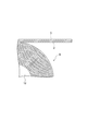
また、第1の巻芯14A及び第2の巻芯14Bのそれぞれは、図6に示すように、巻取対象の接着フィルム1の幅W1よりも大きい幅W2を有している。これにより、第1の巻芯14A及び第2の巻芯14Bのそれぞれで接着フィルム1を巻き取ったリール体Rにおいて、接着フィルム1の巻回体21の側面21aから巻芯14の縁部14aが突出するようになっている。一例として、巻取対象の接着フィルム1の幅W1が50mm以上55mm未満である場合、これを巻き取る巻芯14の幅W2を55mmとすることができる。また、図6の例では、接着フィルム1の幅方向の中心位置に対し、巻芯14の軸方向の中心位置がずれた状態となっている。これにより、リール体Rでは、接着フィルム1の巻回体21における一方の側面21aのみから巻芯14の縁部14aが突出し、他方の側面21aと巻芯14の縁部14aとは面一になっている。
繰出ローラ12から切断部13を経て巻芯14に至る母材B及び複数の接着フィルム1には、巻取張力が付与されている。母材B及び複数の接着フィルム1への巻取張力の付与には、テンションローラを用いてもよく、繰出ローラ12及び巻芯14の軸位置を調整する調整機構を用いてもよい。母材B及び複数の接着フィルム1に付与する巻取張力は、特に制限はないが、例えば60N/m以上となっている。巻取張力は、70N/m以上であってもよく、80N/m以上であってもよい。巻取張力は、例えば150N/m以下となっている。巻取張力は、140N/m以下であってもよく、130N/m以下であってもよい。
[接着フィルム製造方法]
[接着フィルム製造方法]
図7は、接着フィルム製造方法の一実施形態を示すフローチャートである。本実施形態では、接着フィルム製造方法は、上記接着フィルム製造装置11を用いて実施される。この接着フィルム製造方法では、まず、接着フィルム1の母材Bを繰出ローラ12から繰り出す(ステップS01:繰出ステップ)。繰出ステップでは、接着層3が外向きとなるように接着フィルム1の母材Bを繰出ローラ12に巻き回しておく。すなわち、繰出ローラ12には、接着層3が凸状に屈曲するように接着フィルム1の母材Bを巻き回しておく。そして、繰出ローラ12から繰り出された接着フィルム1の母材Bを所定の速度で切断部13に向かって水平に搬送する。
次に、接着フィルム1の母材Bから切断部13によって所定幅の複数の接着フィルム1に切り出す(ステップS02:切断ステップ)。切断ステップでは、切断部13により、接着フィルム1の母材Bから幅の異なる複数の接着フィルム1を切り出す。
複数の接着フィルム1を切り出した後、これらの接着フィルム1のそれぞれを複数の巻芯14によってそれぞれ巻き取る(ステップS03:巻取ステップ)。巻取ステップでは、切断部13から第2の巻芯14Bに向かう接着フィルム1を、接着層3が凸状に屈曲するように搬送して巻き取る。また、第1の巻芯14A及び第2の巻芯14Bのそれぞれで接着フィルム1を巻き取るにあたり、接着フィルム1の幅方向の中心位置に対し、巻芯14の軸方向の中心位置をずらして配置する。これにより、第1の巻芯14A及び第2の巻芯14Bのそれぞれで接着フィルム1を巻き取ったリール体Rにおいて、巻芯14の縁部14aが接着フィルム1の巻回体21の一方の側面21aから突出した状態となる。
[作用効果]
[作用効果]
以上説明したように、接着フィルム製造装置11では、接着フィルム1を巻き取る複数の巻芯14のそれぞれが、巻取対象の接着フィルム1の幅よりも大きい幅を有している。これにより、同一の幅の巻芯14を用いて、巻芯14よりも小さい幅の接着フィルム1の巻き取りを実施できる。したがって、この接着フィルム製造装置11では、用意する巻芯14の種類を削減することが可能となり、リール体Rの作製コストを低減できる。また、巻芯14の縁部14aが巻取対象の接着フィルム1からはみ出すため、巻芯14のはみ出し部分を利用することで、巻芯14に巻き回された接着フィルム1を使用する際、当該接着フィルム1の位置合わせが容易となる。
また、接着フィルム製造装置11では、複数の巻芯14のそれぞれは、当該巻芯14の縁部14aが巻取対象の接着フィルム1から軸方向の片側のみにはみ出すように配置されている。この場合、巻芯14に巻き回された接着フィルム1を使用するにあたり、例えば使用側の装置にリール体Rをセットする際の当該接着フィルム1の位置合わせが一層容易となる。
[変形例]
[変形例]
本開示は、上記実施形態に限られるものではない。図8は、接着フィルム製造装置の別実施形態を示す概略的な斜視図である。図3の例では、繰出ローラ12から繰り出された母材Bが切断部13に向かって水平方向に搬送されているが、図8の例のように、母材Bに張力を付与するローラ31を繰出ローラ12と切断部13との間に配置し、当該ローラ31によって母材Bを凸状に屈曲させてもよい。ローラ31と同様のローラを複数配置し、繰出ローラ12と切断部13との間で母材Bを凸状及び凹状に複数回屈曲させてもよい。この場合、繰出ローラ12から切断部13に向かう母材Bの搬送経路において、母材Bの接着層3が凸状に屈曲する回数が凹状に屈曲する回数以上となっていてもよい。母材Bを複数回屈曲させる場合、最後の屈曲(最も切断部13側での屈曲)は、凸状の屈曲であってもよい。
また、図3の例では、切断部13から第2の巻芯14Bに向かう接着フィルム1の接着層3のみが山なりに屈曲しているが、図8の例のように、母材Bに巻取張力を付与するローラ32を繰出ローラ12と切断部13との間に配置し、当該ローラ32によって接着フィルム1を凸状に屈曲させてもよい。ローラ32と同様のローラを複数配置し、切断部13と巻芯14との間で母材Bを凸状及び凹状に複数回屈曲させてもよい。この場合、切断部13から巻芯14に向かう接着フィルム1の搬送経路において、接着フィルム1の接着層3が凸状に屈曲する回数が凹状に屈曲する回数以上となっていればよい。接着フィルム1を複数回屈曲させる場合、最後の屈曲(最も巻芯14側での屈曲)は、凸状の屈曲であってもよい。
図8の例では、第1の巻芯14Aが位置する第1の軸G1と、第2の巻芯14Bが位置する第2の軸G2とが垂直方向について同位置に位置している。第1の巻芯14Aは、切断部13から第1の巻芯14Aに向かう接着フィルム1の搬送方向がローラ32において略直角に屈曲するように配置され、第2の巻芯14Bは、切断部13から第2の巻芯14Bに向かう接着フィルム1の搬送方向がローラ32において鋭角に屈曲するように配置されている。この結果、切断部13から第1の巻芯14Aに向かう接着フィルム1、及び切断部13から第2の巻芯14Bに向かう接着フィルム1のそれぞれは、接着層3が凸状のみに屈曲して巻芯14によって巻き取られる。
また、例えば図6の例では、接着フィルム1の巻回体21における一方の側面21aのみから巻芯14の縁部14aが突出し、他方の側面21aと巻芯14の縁部14aとは面一になっているが、接着フィルム1の巻回体21における一方及び他方の側面21aから巻芯14の縁部14aがそれぞれ突出していてもよい。すなわち、巻芯14の縁部14aは、接着フィルム1の巻回体21の側面21aから軸方向の両側にはみ出していてもよい。
この場合、接着フィルム1の巻回体21において、一方の側面21aからの巻芯14の縁部14aのはみ出し量と、他方の側面21aからの巻芯14の縁部14aのはみ出し量とが等しくなっていてもよい。また、接着フィルム1の巻回体21における一方の側面21aからの巻芯14の縁部14aのはみ出し量は、他方の側面21aからの巻芯14の縁部14aのはみ出し量より大きくなっていてもよい。このような構成においても、巻芯14に巻き回された接着フィルム1を使用する際、当該接着フィルム1の位置合わせが一層容易となる。一方の側面21aからの巻芯14の縁部14aのはみ出し量に対する他方の側面21aからの巻芯14の縁部14aのはみ出し量の比率は、例えば0.02~5.00であってもよく、0.04~3.00であってもよい。
1…接着フィルム、2…基材層、3…接着層、11…接着フィルム製造装置、12…繰出ローラ、13…切断部、14…巻芯、14a…縁部、B…母材、R…リール体、W1…接着フィルムの幅、W2…巻芯の幅。
Claims (5)
- 接着層を基材層上に有する接着フィルムを製造する接着フィルム製造装置であって、
前記接着フィルムの母材を繰り出す繰出ローラと、
前記接着フィルムの母材を所定幅の複数の接着フィルムに切り出す切断部と、
前記複数の接着フィルムのそれぞれを巻き取る複数の巻芯と、を備え、
前記複数の巻芯のそれぞれは、巻取対象の接着フィルムの幅よりも大きい幅を有している接着フィルム製造装置。 - 前記複数の巻芯のそれぞれは、当該巻芯の縁部が前記巻取対象の接着フィルムから軸方向の片側のみにはみ出すように配置されている請求項1記載の接着フィルム製造装置。
- 接着層を基材層上に有する接着フィルムを巻芯に巻き回してなるリール体であって、
前記巻芯は、前記接着フィルムの幅よりも大きい幅を有しているリール体。 - 前記巻芯の縁部は、前記接着フィルムの巻回体の側面から軸方向の片側のみにはみ出している請求項3記載のリール体。
- 前記巻芯の縁部は、前記接着フィルムの巻回体の側面から軸方向の両側にはみ出しており、前記軸方向の一方のはみ出し量が他方のはみ出し量よりも大きくなっている請求項3記載のリール体。
Priority Applications (4)
| Application Number | Priority Date | Filing Date | Title |
|---|---|---|---|
| CN202180012738.8A CN115052826A (zh) | 2020-02-12 | 2021-01-29 | 黏合膜制造装置及卷轴体 |
| US17/791,996 US12227379B2 (en) | 2020-02-12 | 2021-01-29 | Adhesive film production apparatus and reel bodies |
| KR1020227026816A KR20220137902A (ko) | 2020-02-12 | 2021-01-29 | 접착 필름 제조 장치 및 릴체 |
| PH1/2022/551996A PH12022551996A1 (en) | 2020-02-12 | 2021-01-29 | Adhesive film production apparatus and reel bodies |
Applications Claiming Priority (2)
| Application Number | Priority Date | Filing Date | Title |
|---|---|---|---|
| JP2020021344A JP2021127196A (ja) | 2020-02-12 | 2020-02-12 | 接着フィルム製造装置及びリール体 |
| JP2020-021344 | 2020-02-12 |
Publications (1)
| Publication Number | Publication Date |
|---|---|
| WO2021161815A1 true WO2021161815A1 (ja) | 2021-08-19 |
Family
ID=77292378
Family Applications (1)
| Application Number | Title | Priority Date | Filing Date |
|---|---|---|---|
| PCT/JP2021/003318 Ceased WO2021161815A1 (ja) | 2020-02-12 | 2021-01-29 | 接着フィルム製造装置及びリール体 |
Country Status (7)
| Country | Link |
|---|---|
| US (1) | US12227379B2 (ja) |
| JP (1) | JP2021127196A (ja) |
| KR (1) | KR20220137902A (ja) |
| CN (1) | CN115052826A (ja) |
| PH (1) | PH12022551996A1 (ja) |
| TW (1) | TW202200476A (ja) |
| WO (1) | WO2021161815A1 (ja) |
Families Citing this family (10)
| Publication number | Priority date | Publication date | Assignee | Title |
|---|---|---|---|---|
| JP2021127195A (ja) * | 2020-02-12 | 2021-09-02 | 昭和電工マテリアルズ株式会社 | 接着フィルム製造装置及び接着フィルム製造方法 |
| US12391018B2 (en) * | 2020-04-10 | 2025-08-19 | Rst Automation Llc | Systems and methods for packaging instruments or other items with bag making features |
| JP7631743B2 (ja) * | 2020-11-10 | 2025-02-19 | 株式会社レゾナック | リール体、リール体の製造方法、及び物品の製造方法 |
| KR102648548B1 (ko) | 2021-03-31 | 2024-03-18 | 유니티카 가부시끼가이샤 | 반방향족 폴리아미드 필름 및 그것으로부터 얻어지는 적층체 |
| JP7673562B2 (ja) * | 2021-08-03 | 2025-05-09 | 株式会社三洋物産 | 遊技機 |
| JP7673564B2 (ja) * | 2021-08-03 | 2025-05-09 | 株式会社三洋物産 | 遊技機 |
| JP7673561B2 (ja) * | 2021-08-03 | 2025-05-09 | 株式会社三洋物産 | 遊技機 |
| JP7673563B2 (ja) * | 2021-08-03 | 2025-05-09 | 株式会社三洋物産 | 遊技機 |
| JP7722213B2 (ja) * | 2022-02-14 | 2025-08-13 | 株式会社三洋物産 | 遊技機 |
| JP7729250B2 (ja) * | 2022-05-02 | 2025-08-26 | 株式会社三洋物産 | 遊技機 |
Citations (3)
| Publication number | Priority date | Publication date | Assignee | Title |
|---|---|---|---|---|
| JP2000136056A (ja) * | 1998-10-29 | 2000-05-16 | Matsushita Electronics Industry Corp | 多連リール及び連続巻出し装置 |
| JP2002080167A (ja) * | 2000-06-19 | 2002-03-19 | Sony Chem Corp | ロール及びロール製造装置 |
| WO2014065262A1 (ja) * | 2012-10-23 | 2014-05-01 | 株式会社クレハ | 巻回体の製造方法及び巻回体製造装置 |
Family Cites Families (15)
| Publication number | Priority date | Publication date | Assignee | Title |
|---|---|---|---|---|
| US6700185B1 (en) | 1999-11-10 | 2004-03-02 | Hitachi Chemical Co., Ltd. | Adhesive film for semiconductor, lead frame and semiconductor device using the same, and method for manufacturing semiconductor device |
| JP2005206358A (ja) | 2004-01-26 | 2005-08-04 | Konica Minolta Medical & Graphic Inc | 広幅帯状感光材料の裁断方法及び広幅帯状感光材料用裁断装置 |
| JP4386442B2 (ja) | 2005-03-22 | 2009-12-16 | 富士フイルム株式会社 | ウェブ巻取装置及びスペーサ |
| JPWO2008047546A1 (ja) | 2006-09-29 | 2010-02-25 | 日立化成工業株式会社 | フィルム自動巻取装置、スリット巻取システム及び巻取フィルムの製造方法 |
| JP5532658B2 (ja) | 2008-09-04 | 2014-06-25 | 日立化成株式会社 | 積層体エレメント用感光性接着剤組成物、フィルム状接着剤、接着シート、及び、積層体エレメント |
| JP2010070377A (ja) | 2008-09-22 | 2010-04-02 | Oki Joho Systems:Kk | 媒体処理装置 |
| JP2010120741A (ja) | 2008-11-19 | 2010-06-03 | Canon Inc | カール除去装置および記録装置 |
| KR20120128365A (ko) | 2011-05-17 | 2012-11-27 | 삼성전기주식회사 | 슬리터 |
| JP3172995U (ja) * | 2011-10-31 | 2012-01-19 | 双葉ボビン株式会社 | フィルム巻取用リール |
| JP3209784U (ja) | 2017-01-26 | 2017-04-06 | 秀之 上村 | テープ巻き直し装置 |
| WO2019176599A1 (ja) | 2018-03-12 | 2019-09-19 | 日立化成株式会社 | リール体、包装体及び梱包物 |
| WO2019240923A1 (en) | 2018-06-11 | 2019-12-19 | Dow Global Technologies Llc | Slitting machines and methods for forming rolls of coated films therewith |
| JP7111524B2 (ja) * | 2018-06-25 | 2022-08-02 | 住友化学株式会社 | フィルムの製造方法、フィルム捲回装置 |
| JP2021127195A (ja) * | 2020-02-12 | 2021-09-02 | 昭和電工マテリアルズ株式会社 | 接着フィルム製造装置及び接着フィルム製造方法 |
| JP7631743B2 (ja) * | 2020-11-10 | 2025-02-19 | 株式会社レゾナック | リール体、リール体の製造方法、及び物品の製造方法 |
-
2020
- 2020-02-12 JP JP2020021344A patent/JP2021127196A/ja active Pending
-
2021
- 2021-01-29 KR KR1020227026816A patent/KR20220137902A/ko active Pending
- 2021-01-29 US US17/791,996 patent/US12227379B2/en active Active
- 2021-01-29 CN CN202180012738.8A patent/CN115052826A/zh active Pending
- 2021-01-29 WO PCT/JP2021/003318 patent/WO2021161815A1/ja not_active Ceased
- 2021-01-29 PH PH1/2022/551996A patent/PH12022551996A1/en unknown
- 2021-02-03 TW TW110103962A patent/TW202200476A/zh unknown
Patent Citations (3)
| Publication number | Priority date | Publication date | Assignee | Title |
|---|---|---|---|---|
| JP2000136056A (ja) * | 1998-10-29 | 2000-05-16 | Matsushita Electronics Industry Corp | 多連リール及び連続巻出し装置 |
| JP2002080167A (ja) * | 2000-06-19 | 2002-03-19 | Sony Chem Corp | ロール及びロール製造装置 |
| WO2014065262A1 (ja) * | 2012-10-23 | 2014-05-01 | 株式会社クレハ | 巻回体の製造方法及び巻回体製造装置 |
Also Published As
| Publication number | Publication date |
|---|---|
| TW202200476A (zh) | 2022-01-01 |
| KR20220137902A (ko) | 2022-10-12 |
| US12227379B2 (en) | 2025-02-18 |
| CN115052826A (zh) | 2022-09-13 |
| JP2021127196A (ja) | 2021-09-02 |
| PH12022551996A1 (en) | 2024-01-22 |
| US20230039365A1 (en) | 2023-02-09 |
Similar Documents
| Publication | Publication Date | Title |
|---|---|---|
| WO2021161815A1 (ja) | 接着フィルム製造装置及びリール体 | |
| JP6747621B2 (ja) | 半導体封止成形用仮保護フィルム、仮保護フィルム付きリードフレーム、仮保護フィルム付き封止成形体及び半導体装置を製造する方法 | |
| US12060239B2 (en) | Reel body, method for manufacturing reel body, and method for manufacturing article | |
| US11682564B2 (en) | Temporary protective film for semiconductor encapsulation molding, lead frame provided with temporary protective film, encapsulated molded body provided with temporary protective film, and method for manufacturing semiconductor device | |
| US12134534B2 (en) | Adhesive film production apparatus and adhesive film production method | |
| JP7803713B2 (ja) | 半導体封止成形用仮保護フィルム、仮保護フィルム付きリードフレーム、仮保護フィルム付き封止成形体、及び半導体装置を製造する方法 | |
| JP3575480B2 (ja) | 半導体用接着フィルム |
Legal Events
| Date | Code | Title | Description |
|---|---|---|---|
| 121 | Ep: the epo has been informed by wipo that ep was designated in this application |
Ref document number: 21753077 Country of ref document: EP Kind code of ref document: A1 |
|
| NENP | Non-entry into the national phase |
Ref country code: DE |
|
| 32PN | Ep: public notification in the ep bulletin as address of the adressee cannot be established |
Free format text: NOTING OF LOSS OF RIGHTS PURSUANT TO RULE 112(1) EPC (EPO FORM 1205A DATED 01/12/2022) |
|
| 122 | Ep: pct application non-entry in european phase |
Ref document number: 21753077 Country of ref document: EP Kind code of ref document: A1 |