WO2021156933A1 - 波長クロスコネクト装置及び波長クロスコネクト方法 - Google Patents
波長クロスコネクト装置及び波長クロスコネクト方法 Download PDFInfo
- Publication number
- WO2021156933A1 WO2021156933A1 PCT/JP2020/004101 JP2020004101W WO2021156933A1 WO 2021156933 A1 WO2021156933 A1 WO 2021156933A1 JP 2020004101 W JP2020004101 W JP 2020004101W WO 2021156933 A1 WO2021156933 A1 WO 2021156933A1
- Authority
- WO
- WIPO (PCT)
- Prior art keywords
- band
- wavelength
- wxc
- optical
- optical signal
- Prior art date
- Legal status (The legal status is an assumption and is not a legal conclusion. Google has not performed a legal analysis and makes no representation as to the accuracy of the status listed.)
- Ceased
Links
Images


Classifications
-
- H—ELECTRICITY
- H04—ELECTRIC COMMUNICATION TECHNIQUE
- H04Q—SELECTING
- H04Q11/00—Selecting arrangements for multiplex systems
- H04Q11/0001—Selecting arrangements for multiplex systems using optical switching
- H04Q11/0005—Switch and router aspects
-
- H—ELECTRICITY
- H04—ELECTRIC COMMUNICATION TECHNIQUE
- H04J—MULTIPLEX COMMUNICATION
- H04J14/00—Optical multiplex systems
- H04J14/02—Wavelength-division multiplex systems
-
- H—ELECTRICITY
- H04—ELECTRIC COMMUNICATION TECHNIQUE
- H04Q—SELECTING
- H04Q11/00—Selecting arrangements for multiplex systems
- H04Q11/0001—Selecting arrangements for multiplex systems using optical switching
- H04Q11/0062—Network aspects
-
- H—ELECTRICITY
- H04—ELECTRIC COMMUNICATION TECHNIQUE
- H04B—TRANSMISSION
- H04B10/00—Transmission systems employing electromagnetic waves other than radio-waves, e.g. infrared, visible or ultraviolet light, or employing corpuscular radiation, e.g. quantum communication
- H04B10/29—Repeaters
-
- H—ELECTRICITY
- H04—ELECTRIC COMMUNICATION TECHNIQUE
- H04B—TRANSMISSION
- H04B10/00—Transmission systems employing electromagnetic waves other than radio-waves, e.g. infrared, visible or ultraviolet light, or employing corpuscular radiation, e.g. quantum communication
- H04B10/29—Repeaters
- H04B10/291—Repeaters in which processing or amplification is carried out without conversion of the main signal from optical form
-
- H—ELECTRICITY
- H04—ELECTRIC COMMUNICATION TECHNIQUE
- H04J—MULTIPLEX COMMUNICATION
- H04J14/00—Optical multiplex systems
- H04J14/02—Wavelength-division multiplex systems
- H04J14/0201—Add-and-drop multiplexing
- H04J14/0202—Arrangements therefor
- H04J14/0213—Groups of channels or wave bands arrangements
-
- H—ELECTRICITY
- H04—ELECTRIC COMMUNICATION TECHNIQUE
- H04Q—SELECTING
- H04Q11/00—Selecting arrangements for multiplex systems
- H04Q11/0001—Selecting arrangements for multiplex systems using optical switching
- H04Q11/0005—Switch and router aspects
- H04Q2011/0007—Construction
- H04Q2011/0011—Construction using wavelength conversion
-
- H—ELECTRICITY
- H04—ELECTRIC COMMUNICATION TECHNIQUE
- H04Q—SELECTING
- H04Q11/00—Selecting arrangements for multiplex systems
- H04Q11/0001—Selecting arrangements for multiplex systems using optical switching
- H04Q11/0005—Switch and router aspects
- H04Q2011/0007—Construction
- H04Q2011/0016—Construction using wavelength multiplexing or demultiplexing
-
- H—ELECTRICITY
- H04—ELECTRIC COMMUNICATION TECHNIQUE
- H04Q—SELECTING
- H04Q11/00—Selecting arrangements for multiplex systems
- H04Q11/0001—Selecting arrangements for multiplex systems using optical switching
- H04Q11/0062—Network aspects
- H04Q2011/0079—Operation or maintenance aspects
- H04Q2011/0083—Testing; Monitoring
Definitions
- the present invention relates to a wavelength cross-connect device and a wavelength cross-connect method used for multi-band transmission in which wavelength-multiplexed signal light obtained by multiplexing each optical signal of a plurality of different wavelength bands is transmitted by an optical fiber.
- the wavelength cross-connect device used in a multi-band transmission system is an optical transmission line composed of one or a plurality of optical fibers for transmitting wavelength division multiplexing signal light in which each optical signal of a plurality of different wavelength bands is multiplexed.
- it is an optical node that connects between arbitrary directions in the optical network.
- wavelength cross-connect device wavelength division multiplexing signal light transmitted from the input side route is output to the output side route via a plurality of WSS (Wavelength Selective Switch).
- WSS Widelength Selective Switch
- FIG. 6 shows the configuration of the wavelength cross-connect device 20 used in the conventional multi-band transmission system (also referred to as a system) 10.
- the system 10 has M wavelength band demultiplexers (also referred to as demultiplexers) 11a, 11b, ..., 11m connected for each of the M directions indicated by the reference numerals M (1) on the input side, and the output side. 12a, 12b, ..., 12m of M wavelength band combiners (also referred to as combiners) connected to each of the M directions indicated by the reference numeral M (2). Further, the system 10 has an S-band WXC (Wavelength Cross Connect) unit 21, a C-band WEXC unit 22, and an L-band GXC connected by an optical fiber between the demultiplexer 11a to 11m and the duplexer 12a to 12m. A wavelength cross-connect device 20 having a unit 23 is provided. The S-band WXC unit 21, the C-band WXC unit 22, and the L-band WXC unit 23 are also referred to as WXC units 21 to 23.
- WXC Wavelength Cross Connect
- each WXC unit 21 to 23 has M optical amplifiers 24a, 24b, ..., 24m and M WSS25a, 25b, ..., On the input side. It has 25m. Each WSS 25a-25m has one input end and an M output end (1 ⁇ M). Further, the L band WXC unit 23 has M WSS26a, 26b, ..., 26m having an M input end and one output end (M ⁇ 1) on the output side, and M optical amplifiers 27a, 27b, ..., It has 27m. Each element of these optical amplifiers 24a to 24m, WSS25a to 25m, WSS26a to 26m, and optical amplifiers 27a to 27m is connected by an optical fiber or an optical waveguide.
- the optical amplifiers 24a to 24m, WSS25a to 25m, WSS26a to 26m, and optical amplifiers 27a to are similar to the L band WXC unit 23 described above. It has 27m.
- the wavelength division multiplexing signal lights 1a, 1b, ..., 1m transmitted in multiband for each of the M directions on the input side are input to the demultiplexers 11a to 11m as follows. That is, the wavelength division multiplexing signal light 1a is input to the demultiplexer 11a, the wavelength division multiplexing signal light 1ba is input to the demultiplexer 11b, and the wavelength division multiplexing signal light 1m is input to the demultiplexer 11m.
- each of the wavelength division multiplexing signal lights 1a to 1m is a multiplexing of each optical signal of the S band, C band, and L band of the wavelength band described later.
- Each wavelength band is, in order from the short wavelength side, an S band of 1460 nm to 1530 nm, a C band of 1530 nm to 1565 nm, and an L band of 1565 nm to 1625 nm.
- Each of the S band, C band, and L band optical signals is assigned to the S band, C band, and L band of the optical fiber as a route at the time of transmission.
- S S band
- C C band
- L L band of the optical signal on the transmission path of the optical signal.
- the demultiplexer 11a demultiplexes the wavelength division multiplexing signal light 1a into S-band, C-band, and L-band optical signals, and outputs the light to the optical amplifiers 24a of the WXC units 21 to 23. That is, the demultiplexer 11a outputs the demultiplexed S band light signal to the optical amplifier 24a of the S band WXC unit 21, outputs the C band light signal to the optical amplifier 24a of the C band WXC unit 22, and outputs the L band. The optical signal is output to the optical amplifier 24a of the L band WXC unit 23.
- the other demultiplexers 11b to 11m also demultiplex the wavelength division multiplexing signal light 1b to 1 m into the S band, C band, and L band optical signals, and each WXC unit 21 to 21 to Output to 23 optical amplifiers 24b to 24m.
- the optical amplifiers 24a to 24m of each WXC unit 21 to 23 amplify each optical signal of S band, C band and L band and output to WSS 25a to 25 m of each WXC unit 21 to 23.
- Each WSS 25a to 25m has a function of selecting an optical signal for each wavelength band and adjusting an amount of attenuation.
- the M output terminals for each of WSS 25a to 25 m are connected to the M input terminals of WSS 26a to 26 m on the output side.
- the WSS25a outputs an L-band light signal from the first output end described at the top to the second input end of the WSS26a on the output side, and outputs an L-band light signal from the second output end to the output side. It is output to the input end of the WSS, and the L band light signal is output from the third output end to the first input end of the WSS 26m on the output side. In this way, the L band light signal is output from each output end of one WSS25a to different input ends of WSS26a to 26m.
- Each of WSS26a to 26m on the output side sequentially selects optical signals of a plurality of wavelength bands input from M input ends and outputs them from one output end to the optical amplifiers 27a to 27m.
- each optical amplifier 27a to 27m The output ends of each optical amplifier 27a to 27m are connected to the combiner 12a to 12m.
- the optical amplifiers 27a to 27m amplify each of the S band, C band, and L band optical signals and then output them to the corresponding combiner 12a to 12m.
- each of the combiners 12a to 12m combines the S-band, C-band, and L-band optical signals amplified by the optical amplifiers 27a to 27m of the WXC units 21 to 23.
- the wavelength division multiplexing signal light generated by this combined wave is multiband transmitted to M directions M (2).
- Non-Patent Document 1 As a conventional technique relating to such a wavelength cross-connect device 20, there is one described in Non-Patent Document 1.
- the wavelength cross-connect device 20 described above supports multi-band transmission, and the S-band WXC section 21 and C-band corresponding to the S-band, C-band, and L-band optical signals demultiplexed by the demultiplexer 11a. It is necessary to include the WXC unit 22 and the L band WXC unit 23. Therefore, the scale of the device and the power consumption of the device are more than three times as large as those of the wavelength cross-connect device for a single band.
- the transmission performance of each optical signal in the S band, C band and L band is improved. There is a difference. For example, the wavelength band dependence of the transmission band and light loss in a WSS or an optical amplifier occurs.
- the technical maturity level of the components used for the optical device differs depending on the wavelength band. If the technology maturity period for improving optical components required to ensure a certain level of optical performance (transmission band, light loss, etc.) differs depending on the wavelength band, the optical device in the wavelength band that requires the most technology maturity period.
- the realization time of multi-band compatible WXC will be rate-determined by the technological maturity of. For example, the technological maturity level of optical devices is highest in the C band, which is most often applied to general optical transmission systems, and is lowest in the order of L band and S band. Therefore, there is a problem that the realization time of the multi-band compatible WXC is rate-determined by the realization of the S-band optical device that requires a technology readiness period.
- the present invention has been made in view of such circumstances, the scale of the apparatus and the power consumption can be reduced, the difference in the transmission performance of each optical signal due to the different wavelength bands of WXC is eliminated, and the wavelength requiring the most technological maturity period. It is an object of the present invention to prevent the realization time of the multi-band compatible WXC from being rate-determined by the band optical device.
- the wavelength cross-connect device of the present invention multiplexes each optical signal of a plurality of different wavelength bands that have been multiband-transmitted in an optical transmission line composed of one or a plurality of optical fibers.
- the wavelength multiplex signal light is divided into different wavelength bands for each direction.
- WSS Widelength Selective Switch
- the direction is changed by WSS (Wavelength Selective Switch) to the output side.
- a wavelength cross-connect device that performs relay processing for outputting to a road, having the optical amplifier and the WSS, and performing the relay processing of an optical signal in a predetermined specific wavelength band among the different wavelength bands.
- a WXC (Wavelength Cross Connect) unit having the same number as the number of wavelength bands of the optical signal in each wavelength band is provided, and an optical signal in a wavelength band other than the specific wavelength band is transmitted to the input side of the WXC unit in the specific wavelength band.
- An input-side conversion unit that converts an optical signal is provided, and an output-side conversion unit that converts an optical signal of a specific wavelength band converted by the input-side conversion unit into an optical signal before conversion is provided on the output side of the WXC unit.
- the optical signal of the specific wavelength band directly input from the input side is directly output after the relay process in the WXC unit.
- the device scale and power consumption can be reduced, the difference in transmission performance of each optical signal due to different wavelength bands of WXC is eliminated, and the optical device of the wavelength band that requires the most technological maturity period can be used to obtain a multi-band compatible WXC. It is possible to avoid that the realization time is rate-determined.
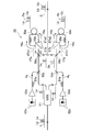
- FIG. 1 is a block diagram showing a configuration of a multi-band transmission system using the wavelength cross-connect device according to the embodiment of the present invention.
- the wavelength cross-connect device 20A performs the C-band WXC unit 22 related to the C-band, which is the wavelength band (referred to as a specific wavelength band) having the highest technical maturity of the above-mentioned WXC component, at every wavelength band demultiplexer 11a to 11m. It has the same number of wavelength bands to be demultiplexed. In this example, it is assumed that the number of wavelength bands is three, S band, C band, and L band. In this case, the configuration is such that three C-band WXC units 22 are provided.
- the C-band WXC unit 22 constitutes the WXC unit according to claim.
- the wavelength cross-connect device 20A converts an optical signal in a wavelength band (S band and L band) other than the specific wavelength band (C band) into an optical signal in the specific wavelength band (C band) on the input side. It includes an S / C conversion unit 31 and an L / C conversion unit 32 as units.
- the S / C conversion unit 31 converts the S band light signal into a C band light signal
- the L / C conversion unit 32 converts the L band light signal into a C band light signal.
- the S / C conversion unit 31 and the L / C conversion unit 32 form the input-side conversion unit according to the claim.
- connection configuration between each output end of the demultiplexer 11a to 11m and the input end of the three C-band WXC units 22 is as follows. That is, the output ends of the S-band optical signals of the demultiplexers 11a to 11m are connected to the optical amplifiers 24a to 24m of the first C-band WXC unit 22 via the S / C conversion unit 31. Further, the output ends of the C-band optical signals of the demultiplexers 11a to 11m are directly connected to the input ends of the optical amplifiers 24a to 24m of the second C-band WXC unit 22. Further, the output ends of the L-band optical signals of the demultiplexers 11a to 11m are connected to the input ends of the optical amplifiers 24a to 24m of the third C-band WXC unit 22 via the L / C conversion unit 32.
- the wavelength cross-connect device 20A includes a C / S conversion unit 35 and a C / L conversion unit 36 connected to the optical amplifiers 27a to 27m on the output side.
- FIG. 1 represents the C / L conversion unit 36 connected to the optical amplifiers 27a to 27m as a representative.
- the C / S conversion unit 35 converts the C-band light signal converted from the S-band light signal by the S / C conversion unit 31 on the input side into an S-band light signal.
- the C / L conversion unit 36 includes a C / L conversion unit 36 that converts a C-band light signal converted from an L-band light signal by the L / C conversion unit 32 on the input side into an L-band light signal.
- the C / S conversion unit 35 and the C / L conversion unit 36 constitute the output-side conversion unit according to the claim.
- the output end of the C band optical signal directly input in the C band WXC unit 22 is directly connected to the input end of the combiner 12a to 12m.
- FIG. 2 shows the circuit configuration of the L / C conversion unit 32 as a representative, and a description thereof will be given.
- the L / C conversion unit 32 shown in FIG. 2 includes a WSS 51, wavelength variable light sources 52a and 52b, amplifiers 53a and 53b, polarization controllers 54a and 54b, and WDM (Wavelength Division Multiplexing) couplers 55a, 55b and 56a. It includes 56b, polarization beam splitters 57a and 57b, polarization controllers 58a and 58b, loop-shaped highly non-linear fibers 59a and 59b, and an optical coupler 60.
- a indicates a component on the long wavelength side of the optical signal
- b indicates a component on the short wavelength side of the optical signal
- the polarization beam splitter 57a connects two input / output ports 57a1 and 57a2 in a loop shape with an optical fiber, and a loop-shaped high non-linear fiber 59a is connected in the middle of the optical fiber. Further, a polarization controller 58a is connected between one input / output port 57a1 of the polarization beam splitter 57a and the highly non-linear fiber 59a.
- the polarization beam splitter 57b connects two input / output ports 57b1 and 57b2 in a loop shape with an optical fiber, and a loop-shaped high non-linear fiber 59b is connected in the middle of the optical fiber. Further, a polarization controller 58b is connected between one input / output port 57b1 of the polarization beam splitter 57b and the highly non-linear fiber 59b.
- the pump light output from the wavelength-variable light source 52a is amplified by the amplifier 53a, and the pump light Pa whose polarization is controlled by the polarization controller 54a is input to the polarization beam splitter 57a via the WDM couplers 55a and 56a.
- the pump light Pa is input to the polarization beam splitter 57a in a linearly polarized state tilted by 45 degrees with respect to the main axis of the polarization beam splitter 57a.
- the tilt of 45 degrees is realized by the polarization control of the polarization controller 54a.
- the pump light output from the wavelength variable light source 52b is amplified by the amplifier 53b, and the pump light Pb whose polarization is controlled by the polarization controller 54b is input to the polarization beam splitter 57b via the WDM couplers 55b and 56b. ..
- the pump light Pb is input to the polarization beam splitter 57b in a linearly polarized state tilted by 45 degrees with respect to the main axis of the polarization beam splitter 57b.
- the tilt of 45 degrees is realized by the polarization control of the polarization controller 54b.
- the L band light signal (also referred to as optical signal L) from the demultiplexer 11a shown in FIG. 1 is input to the WSS 51 shown in FIG. 2 of the L / C conversion unit 32.
- this optical signal L an optical signal of the long wavelength side La (also referred to as a long wavelength side optical signal La) and an optical signal of the short wavelength side Lb (also referred to as a short wavelength side optical signal Lb) are combined.
- the WSS 51 divides the optical signal L into a long wavelength side optical signal La and a short wavelength side optical signal Lb and outputs the optical signal L.
- This long wavelength side optical signal La is input to the polarization beam splitter 57a via the WDM couplers 55a and 56a.
- the short wavelength side optical signal Lb is input to the polarization beam splitter 57b via the WDM couplers 55b and 56b.
- the long wavelength side optical signal La and the pump light Pa input to the polarization beam splitter 57a are output from the first input / output port 57a1 of the polarization beam splitter 57a, and are indicated by an arrow Y5a. As shown, it follows a loop path input to the second input / output port 57a2 via the polarization controller 58a and the highly nonlinear fiber 59a.
- the long wavelength side optical signal La and the pump optical Pa output from the first input / output port 57a1 of the polarization beam splitter 57a are polarized by the polarization controller 58a and are controlled by the highly nonlinear fiber 59a.
- the highly non-linear fiber 59a is an optical fiber having a high non-linear constant as a parameter, and efficiently causes four-wave mixing in a loop to perform wavelength band conversion.
- the highly non-linear fiber 59a is a new one wavelength band by interacting two wavelength bands of the long wavelength side optical signal La and the pump light Pa as a non-linear optical intermodulation phenomenon by the four-wave mixing process.
- An optical signal Ca on the long wavelength side of the C band is generated.
- the generated optical signal Ca, the long wavelength side optical signal La, and the pump optical Pa are input to the second input / output port 57a2 of the polarization beam splitter 57a.
- the long wavelength side optical signal La and the pump optical Pa input to the polarization beam splitter 57a are output from the second input / output port 57a2 and are high as shown by the arrow Y6a in the direction opposite to the arrow Y5a. It follows a loop path input to the first input / output port 57a1 via the non-linear fiber 59a and the polarization controller 58a. In this loop path as well, a new optical signal (also referred to as a long wavelength side optical signal Ca) of the C band long wavelength side Ca is newly generated by the four-wave mixing process.
- a new optical signal also referred to as a long wavelength side optical signal Ca
- the two long wavelength side optical signals Ca generated by following the loop path in both directions are wavelength-multiplexed by the polarization beam splitter 57a. As shown by the arrow Y7a, the long wavelength side optical signal Ca is output toward the input side, extracted by the WDM coupler 56a, and output to the optical coupler 60.
- the same wavelength band conversion process as on the long wavelength side is performed. That is, the long wavelength side optical signal Lb and the pump light Pb input to the polarization beam splitter 57b are output from the first input / output port 57b1 of the polarization beam splitter 57b, and as shown by the arrow Y5b, the polarization controller 58b And the loop path input to the second input / output port 57b2 via the highly non-linear fiber 59b is followed.
- the long wavelength side optical signal Lb and the pump light Pb output from the first input / output port 57b1 are subjected to four-wave mixing processing by the highly nonlinear fiber 59b while the polarization is controlled by the polarization controller 58b. ..
- a new optical signal Cb on the short wavelength side of the C band is generated, and is input to the second input / output port 57b2 of the polarization beam splitter 57b together with the long wavelength side optical signal Lb and the pump light Pb.
- the long wavelength side optical signal Lb and the pump light Pb follow the loop path indicated by the arrow Y6b in the direction opposite to the arrow Y5b from the second input / output port 57b2 of the polarization beam splitter 57b.
- a new optical signal on the short wavelength side Cb in the C band (also referred to as a short wavelength side optical signal Cb) is newly generated by the four-wave mixing process.
- the two short wavelength side optical signals Cb generated by following the loop path in both directions are wavelength-multiplexed by the polarization beam splitter 57b, output to the input side indicated by the arrow Y7b, and optical coupler via the WDM coupler 56b. It is output to 60.
- the optical coupler 60 combines the long wavelength side optical signal Ca and the short wavelength side optical signal Cb into a C band optical signal.
- the L / C conversion unit 32 converts the L-band light signal from the demultiplexer 11a into a C-band light signal. This converted C-band optical signal is input to the optical amplifier 24a of the C-band WXC unit 22.
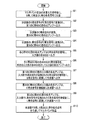
- step S1 shown in FIG. 3 the wavelength division multiplexing signal light 1a to 1m transmitted in multiband from the input side direction M (1) shown in FIG. 1 is the wavelength division multiplexing signal light 1a by the demultiplexers 11a to 11m. Every ⁇ 1 m, it is demultiplexed into S band, C band and L band optical signals.
- step S2 the demultiplexed S band light signal is converted into a C band light signal by each S / C conversion unit 31 and output to the optical amplifiers 24b to 24 m of the first C band WXC unit 22.
- step S3 the demultiplexed C-band optical signal is directly output to the optical amplifiers 24a to 24m of the second C-band WXC unit 22.
- step S4 the demultiplexed L-band light signal is converted into a C-band light signal by each L / C conversion unit 32 and output to the optical amplifiers 24b to 24m of the third C-band WXC unit 22.
- the processes of steps S2 to S4 may be executed in any order.
- step S5 each optical amplifier 24a to 24m of each C band WXC unit 22 amplifies the C band optical signal and outputs it to each WSS 25a to 25m.
- each WSS 25a to 25m of each C band WXC unit 22 outputs the input C band optical signal to the optical amplifier 27a to 27m via a predetermined output side WSS 26a to 26m.
- each optical amplifier 27a to 27m on the output side of the first C band WXC unit 22 amplifies the C band optical signal converted by the S / C conversion unit 31 on the input side, and the C / S conversion unit. Output to 35.
- the C / S conversion unit 35 converts the C-band light signal converted on the input side into an S-band light signal and outputs it to the combiner 12a to 12m.
- step S8 the optical amplifiers 27a to 27m of the second C-band WXC unit 22 amplify the C-band optical signal and directly output it to each of the combiners 12a to 12m.
- each optical amplifier 27a to 27m on the output side of the third C band WXC unit 22 amplifies the C band optical signal converted by the L / C conversion unit 32 on the input side, and the C / L conversion unit. Output to 36.
- the C / L conversion unit 36 converts the C-band light signal converted on the input side into an L-band light signal and outputs it to the combiner 12a to 12m.
- the processes in steps S7 to S9 may be executed in any order.
- step S10 the combiners 12a to 12m combine the input S-band, C-band, and L-band optical signals and transmit the multi-band to the M directions M (2) on the output side. do.
- the wavelength cross-connect device 20A of the present embodiment is a wavelength division multiplexing signal light 1a transmitted in multiple bands from a plurality of directions M (1) in which one or a plurality of optical fibers are bundled in one way M (1). After amplifying the optical signal of each wavelength band demultiplexed into different wavelength bands (S band, C band and L band) for each direction M (1), the direction is changed by WSS. Then, a relay process of outputting to the output side route M (2) is performed.
- the wavelength cross-connect device 20A has optical amplifiers 24b to 24m, 27a to 27m, and WSS 25a to 25m, 26a to 26m, and has a predetermined specific wavelength band (C band) of light among different wavelength bands.
- a C-band WXC unit 22 having the same number of wavelength bands as the number of wavelength bands of the optical signal of each wavelength band for performing signal relay processing is provided. Further, on the input side of the C band WXC unit 22, an input side conversion unit (S / C conversion unit 31 and L / C conversion unit 31) that converts an optical signal in a wavelength band other than the specific wavelength band into an optical signal in a specific wavelength band.
- the output side conversion unit (C / S conversion) that converts the optical signal of the specific wavelength band converted by the input side conversion unit into the optical signal before the conversion.
- a unit 35 and a C / L conversion unit 36) are provided.
- the optical signal of the specific wavelength band directly input from the input side is directly output after the relay processing in the C band WXC unit 22.
- the C-band WXC unit 22 that relays the optical signal of the specific wavelength band is provided with the same number of wavelength bands of each optical signal that is demultiplexed into different wavelength bands on the input side of the C-band WXC unit 22. ..
- An optical signal in a wavelength band other than the specific wavelength band on the input side is converted into an optical signal in the specific wavelength band by the input side conversion unit, and is input to the C band WXC unit 22 related to the wavelength band other than the specific wavelength band.
- the optical signal of the specific wavelength band on the input side is directly input to the C band WXC unit 22 related to the specific wavelength band. Therefore, all C-band WXC units 22 perform relay processing with optical signals of a specific wavelength band which is the same wavelength band.
- the output side conversion unit converts it to the optical signal before the conversion.
- the optical signal of the specific wavelength band directly input from the input side is directly output after the relay processing in the C band WXC unit 22.
- all C-band WXC units 22 have the same optical characteristics because they have a function of processing optical signals in the same wavelength band (specific wavelength band). In other words, in all the C-band WXC units 22, the difference in optical characteristics due to the difference in the wavelength band of the conventional multi-band transmission disappears.
- each C band WXC unit 22 corresponds to optical signal processing in different wavelength bands, but in the present invention, optical signal processing can be performed in the same wavelength band (specific wavelength band). Therefore, parts such as electric parts and mechanical parts can be shared, so that the device scale and power consumption of the C-band WXC unit 22 can be reduced.
- each C-band WXC unit 22 the technical maturity of the components (WSS 25a to 25 m, 26a to 26 m and optical amplifiers 24b to 24 m, 27a to 27 m) is determined by each C-band WXC unit 22 as in the conventional case. It is possible to eliminate the limitation of the transmission performance of the other C-band WXC unit 22 by the S-band WXC unit 21 (FIG. 6) related to the wavelength band to be lowered. That is, it is possible to avoid that the realization time of the multi-band compatible WXC is rate-determined by the optical device in the wavelength band (S band) that requires the most technological maturity period.
- the specific wavelength band is a wavelength band (C band) that maximizes the technology readiness level among the wavelength bands that differ in the technology readiness level of the components related to the transmission performance of the C band WXC unit 22. ..
- all C-band WXC units 22 have components related to a specific wavelength band that maximizes the technical maturity level, so that all C-band WXC units 22 can have the highest transmission performance. Can be unified to.
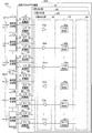
- FIG. 4 is a block diagram showing a configuration of a multi-band transmission system using the wavelength cross-connect device according to the first modification of the embodiment of the present invention.
- the wavelength cross-connect device 20B of the first modification shown in FIG. 4 has M optical amplifiers on the input side in the three C-band WXC units 22 in the same manner as the wavelength cross-connect device 20A (FIG. 1) of the above-described embodiment. It is provided with various functional components of 24a to 24m and M WSS 25a to 25m, and M WSS 26a to 26m on the output side and M optical amplifiers 27a to 27m.
- the feature of the wavelength cross-connect device 20B is that the components of various functions in the three C-band WXC units 22 are collectively configured for each component of the same type on the input side or the output side, and the device has a single housing ( It is a point realized by (called a housing device).
- the optical amplifiers 24a on the input side which are arranged one by one for each of the three C-band WXC units 22, are configured (or array-configured) as a group of three to form one housing device.
- the other optical amplifiers 24b to 24m also form one optical amplifier device 41 by forming three optical amplifiers of the three C-band WXC units 22 together.
- the WSS 25a on the input side which is arranged one by one for each of the three C-band WXC units 22, is configured as a group of three to form one WSS device (with the WSS device 42). It is called).
- each of the other WSSs 25b to 25m also comprises three WSSs of the three C-band WXC portions 22 as one WSS device 42.
- the WSS26a of the three C-band WXC portions 22 is configured as a group of three to form one WSS device 43 shown by a broken line frame.
- each of the other WSS 26b to 26 m is also configured as one WSS device 43.
- optical amplifiers 27a on the output side of the three C-band WXC units 22 are configured as a group of three to form one optical amplifier device 44 shown by a broken line frame.
- each of the other optical amplifiers 27a to 27m is also configured as one optical amplifier device 44.
- the components of various functions represented by the optical amplifiers 24b to 24m, 27a to 27m and WSS25a to 25m, 26a to 26m of all C band WXC units 22 are spread over all C band WXC units 22.
- the housing devices 41 to 44 which are configured as a group for each of the same types.
- the scale can be made smaller than the scale when the three C-band WXC units 22 are simply combined, and the power consumption can be reduced.
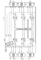
- FIG. 5 is a block diagram showing a configuration of a multi-band transmission system using the wavelength cross-connect device according to the second modification of the embodiment of the present invention.
- the feature of the wavelength cross-connect device 20B of the multi-band transmission system 20C of the modification 2 shown in FIG. 5 is that the same type of components on the input side and the output side are collectively configured for each of the three C-band WXC units 22. The point is that it is realized by two housing devices.
- optical amplifiers 24a to 24m on the input side and M optical amplifiers on the output side are connected.
- the optical amplifiers 27a to 27m of the above are collectively configured (or array-configured) to form an optical amplifier device (referred to as an optical amplifier device 46) as one housing device.
- WSS device 47 As shown by the alternate long and short dash line frame 47, in the C band WXC unit 22 to which the L / C conversion unit 32 on the input side is connected, M WSS 25a to 25 m on the input side and M WSS 26a to 26 m on the output side. And were collectively configured as one WSS device (referred to as WSS device 47).
- the optical amplifiers 24a to 24m on the input side and the optical amplifiers 27a to 27m on the output side are collectively configured. Then, one optical amplifier device 46 was used.
- the M WSS 25a to 25 m on the input side and the M WSS 26a to 26 m on the output side are grouped together. It was made into one WSS device 47.
- the optical amplifiers 24b to 24m on the input side and the optical amplifiers 27a to 27m on the output side are collectively configured as one.
- the optical amplifier device 46 was used.
- the WSS 25a to 25 m on the input side and the WSS 26a to 26 m on the output side are collectively configured to form one WSS device 47. ..
- the two-dot chain line frame 48 connected between the output end of WSS 25a to 25 m on the input side and the input end of WSS 26a to 26 m on the output side has the same light as the optical wiring surrounded by the two-dot chain line frame 48 in FIG. Indicates that the wiring has been deployed. That is, the output ends of WSS 25a to 25 m on the input side and the input ends of WSS 26a to 26 m on the output side are connected by the optical wiring shown by the chain double-dashed line frame 48.
- a housing device 46 in which components of various functions represented by optical amplifiers 24b to 24m, 27a to 27m, and WSS 25a to 25m, 26a to 26m are collectively configured for each type of all C band WXC units 22. , 47.
- each C-band WXC unit 22 the same type of components on the input side and the output side are collectively configured and realized by one housing device 46, 47.
- parts such as electrical parts and mechanical parts can be shared. Therefore, the scale can be made smaller than the scale when the three C-band WXC units 22 are simply combined, and the power consumption can be reduced.
- the wavelength cross-connect device of the present invention wherein the wavelength cross-connect device is each of a plurality of different wavelength bands that have been multiband-transmitted in an optical transmission line composed of one or a plurality of optical fibers.
- Wavelength-multiplexed signal light obtained by multiplexing optical signals is divided into different wavelength bands for each direction.
- WSS Widelength Selective Switch
- WSS Widelength Selective Switch
- a WXC (Wavelength Cross Connect) unit having the same number as the number of wavelength bands of the optical signal in each wavelength band is provided, and an optical signal in a wavelength band other than the specific wavelength band is transmitted to the input side of the WXC unit in the specific wavelength band.
- An input-side conversion unit that converts an optical signal is provided, and an output-side conversion unit that converts an optical signal of a specific wavelength band converted by the input-side conversion unit into an optical signal before conversion is provided on the output side of the WXC unit.
- the optical signal of the specific wavelength band directly input from the input side is directly output after the relay process in the WXC unit.
- the WXC unit that relays the optical signal of a specific wavelength band is provided with the same number of wavelength bands of each optical signal that is demultiplexed into different wavelength bands on the input side of the WXC unit.
- An optical signal in a wavelength band other than the specific wavelength band on the input side is converted into an optical signal in the specific wavelength band by the input side conversion unit, and is input to the WXC unit related to the wavelength band other than the specific wavelength band.
- the optical signal of the specific wavelength band on the input side is directly input to the WXC unit related to the specific wavelength band. Therefore, all WXC units perform relay processing with optical signals in a specific wavelength band which is the same wavelength band.
- the output side conversion unit converts the optical signal into the optical signal before the conversion.
- the optical signal of the specific wavelength band directly input from the input side is directly output after the relay processing in the WXC unit.
- all WXC units have the same optical characteristics because they have a function of processing optical signals in the same wavelength band (specific wavelength band). In other words, in all WXC units, there is no difference in optical characteristics due to the difference in wavelength band of multi-band transmission as in the past.
- each WXC unit corresponds to optical signal processing in different wavelength bands, but in the present invention, optical signal processing can be performed in the same wavelength band (specific wavelength band). Therefore, parts such as electric parts and mechanical parts can be shared, so that the device scale and power consumption of the WXC unit can be reduced.
- the transmission performance of other WXC sections is limited by the WXC section related to the wavelength band that lowers the technical maturity of the components (WSS and optical amplifier) in each WXC section as in the past. It is possible to eliminate such things as. That is, in the present invention, it is possible to avoid that the realization time of the multi-band compatible WXC is rate-determined by the optical device in the wavelength band that requires the most technological maturity period.
- the specific wavelength band is the wavelength band that maximizes the technology readiness level among the wavelength bands that differ in the technology readiness level of the components related to the transmission performance of the WXC unit. It is a feature.
- all WXC units have components related to a specific wavelength band that maximizes the technology readiness level, so that all WXC units can be unified into functions that can maximize transmission performance.
- the housing device when all WXC units are, for example, three, a total of three components provided for each of the three WXC units are grouped together to form one housing device.
- parts such as electric parts and mechanical parts of the three components can be shared. Therefore, one housing device can be made smaller than the scale when the three WXC units are simply combined, and the power consumption can be reduced.
- each WXC unit is provided with a housing device in which the optical amplifier and the components of various functions represented by the WSS are collectively configured for each type. It is characterized by.
- Wavelength division multiplexing signal light 11a to 11m Wavelength band demultiplexer 12a to 12m Wavelength band duplexer 20A, 20B, 20C Wavelength cross-connect device 22C band WXC section 24b to 24m, 27a to 27m
Landscapes
- Engineering & Computer Science (AREA)
- Computer Networks & Wireless Communication (AREA)
- Signal Processing (AREA)
- Physics & Mathematics (AREA)
- Electromagnetism (AREA)
- Optical Communication System (AREA)
Priority Applications (3)
| Application Number | Priority Date | Filing Date | Title |
|---|---|---|---|
| PCT/JP2020/004101 WO2021156933A1 (ja) | 2020-02-04 | 2020-02-04 | 波長クロスコネクト装置及び波長クロスコネクト方法 |
| JP2021575125A JP7294461B2 (ja) | 2020-02-04 | 2020-02-04 | 波長クロスコネクト装置及び波長クロスコネクト方法 |
| US17/794,347 US11979226B2 (en) | 2020-02-04 | 2020-02-04 | Wavelength cross connect device and wavelength cross connect method |
Applications Claiming Priority (1)
| Application Number | Priority Date | Filing Date | Title |
|---|---|---|---|
| PCT/JP2020/004101 WO2021156933A1 (ja) | 2020-02-04 | 2020-02-04 | 波長クロスコネクト装置及び波長クロスコネクト方法 |
Publications (1)
| Publication Number | Publication Date |
|---|---|
| WO2021156933A1 true WO2021156933A1 (ja) | 2021-08-12 |
Family
ID=77199861
Family Applications (1)
| Application Number | Title | Priority Date | Filing Date |
|---|---|---|---|
| PCT/JP2020/004101 Ceased WO2021156933A1 (ja) | 2020-02-04 | 2020-02-04 | 波長クロスコネクト装置及び波長クロスコネクト方法 |
Country Status (3)
| Country | Link |
|---|---|
| US (1) | US11979226B2 (cg-RX-API-DMAC7.html) |
| JP (1) | JP7294461B2 (cg-RX-API-DMAC7.html) |
| WO (1) | WO2021156933A1 (cg-RX-API-DMAC7.html) |
Families Citing this family (1)
| Publication number | Priority date | Publication date | Assignee | Title |
|---|---|---|---|---|
| US12563323B2 (en) * | 2021-06-07 | 2026-02-24 | Ntt, Inc. | Wavelength cross connect device, and wavelength cross connect method |
Citations (4)
| Publication number | Priority date | Publication date | Assignee | Title |
|---|---|---|---|---|
| JP2000115133A (ja) * | 1998-10-05 | 2000-04-21 | Fujitsu Ltd | 光パスクロスコネクト装置及び光ネットワーク |
| JP2002101432A (ja) * | 2000-07-21 | 2002-04-05 | Fujitsu Ltd | 光スイッチ網、光クロスコネクト装置および光分岐・挿入装置 |
| JP2003188830A (ja) * | 2001-12-20 | 2003-07-04 | Nikon Corp | 波長多重光伝送用装置、中継装置、分配装置及び波長多重光伝送システム |
| JP2004254157A (ja) * | 2003-02-21 | 2004-09-09 | Fujitsu Ltd | 光クロスコネクト装置 |
Family Cites Families (15)
| Publication number | Priority date | Publication date | Assignee | Title |
|---|---|---|---|---|
| US6509987B1 (en) * | 1999-08-10 | 2003-01-21 | Lucent Technologies | Channel band conversion apparatus for optical transmission systems |
| US6501597B1 (en) * | 2001-08-07 | 2002-12-31 | Spectralane, Inc. | Optical amplifier using wavelength converter |
| ITMI20011817A1 (it) * | 2001-08-28 | 2003-02-28 | Marconi Comm Spa | Dispositivi per la commutazione ottica di lunghezze d'onda in reti ditelecomunicazione |
| JP4030441B2 (ja) * | 2003-02-26 | 2008-01-09 | 富士通株式会社 | 光クロスコネクト装置 |
| JP5304316B2 (ja) * | 2009-02-27 | 2013-10-02 | 富士通株式会社 | 光受信装置および制御装置 |
| US9130692B2 (en) * | 2012-04-23 | 2015-09-08 | Coriant Operations, Inc. | Reconfigurable optical add/drop multiplexer network element for C-band and L-band optical signals |
| US10797817B2 (en) * | 2016-12-28 | 2020-10-06 | Nippon Telegraph And Telephone Corporation | Optical signal processing device |
| US10237633B2 (en) * | 2017-02-16 | 2019-03-19 | Ciena Corporation | Systems and methods for modular deployment and upgrade of multiple optical spectrum bands in optical transmission systems |
| JP2018191074A (ja) * | 2017-04-28 | 2018-11-29 | 富士通株式会社 | 伝送装置及び伝送方法 |
| JP7106835B2 (ja) * | 2017-10-06 | 2022-07-27 | 富士通株式会社 | 光伝送装置、波長変換装置、光伝送方法、および波長変換方法 |
| JP7000984B2 (ja) * | 2018-05-10 | 2022-01-19 | 富士通株式会社 | 波長分割多重光信号のパワーを調整する装置および方法 |
| JP7183581B2 (ja) * | 2018-06-15 | 2022-12-06 | 富士通株式会社 | 光伝送システム、制御装置、光伝送方法及び伝送装置 |
| GB2574888B (en) * | 2018-06-22 | 2022-08-10 | Huber Suhner Polatis Ltd | Multiple wavelength band optical switching unit |
| JP7147626B2 (ja) * | 2019-02-25 | 2022-10-05 | 富士通株式会社 | 伝送装置及び伝送システム |
| US10903930B1 (en) * | 2020-01-31 | 2021-01-26 | Fujitsu Limited | In-service defragmentation in optical networks using wavelength conversion |
-
2020
- 2020-02-04 US US17/794,347 patent/US11979226B2/en active Active
- 2020-02-04 JP JP2021575125A patent/JP7294461B2/ja active Active
- 2020-02-04 WO PCT/JP2020/004101 patent/WO2021156933A1/ja not_active Ceased
Patent Citations (4)
| Publication number | Priority date | Publication date | Assignee | Title |
|---|---|---|---|---|
| JP2000115133A (ja) * | 1998-10-05 | 2000-04-21 | Fujitsu Ltd | 光パスクロスコネクト装置及び光ネットワーク |
| JP2002101432A (ja) * | 2000-07-21 | 2002-04-05 | Fujitsu Ltd | 光スイッチ網、光クロスコネクト装置および光分岐・挿入装置 |
| JP2003188830A (ja) * | 2001-12-20 | 2003-07-04 | Nikon Corp | 波長多重光伝送用装置、中継装置、分配装置及び波長多重光伝送システム |
| JP2004254157A (ja) * | 2003-02-21 | 2004-09-09 | Fujitsu Ltd | 光クロスコネクト装置 |
Also Published As
| Publication number | Publication date |
|---|---|
| JP7294461B2 (ja) | 2023-06-20 |
| JPWO2021156933A1 (cg-RX-API-DMAC7.html) | 2021-08-12 |
| US20230067932A1 (en) | 2023-03-02 |
| US11979226B2 (en) | 2024-05-07 |
Similar Documents
| Publication | Publication Date | Title |
|---|---|---|
| US6271949B1 (en) | Optical communication system using wavelength-division multiplexed light | |
| US20060098981A1 (en) | Optical transmitting apparatus, method of increasing the number of paths of the apparatus, and optical switch module for increasing the number of paths of the apparatus | |
| JP7472982B2 (ja) | 波長クロスコネクト装置、マルチバンド伝送システム及びマルチバンド伝送方法 | |
| JP7544124B2 (ja) | 波長クロスコネクト装置及び波長クロスコネクト方法 | |
| US11637646B2 (en) | Apparatus and method for coherent optical multiplexing 1+1 protection | |
| US8861966B2 (en) | Method and system for band blocking in an optical telecommunication network | |
| US11824583B2 (en) | Cyclic wavelength band replacement device, multi-band transmission system, and cyclic wavelength band replacement method | |
| JP7135783B2 (ja) | 伝送システム、伝送装置、及び伝送方法 | |
| JPWO2022009292A5 (cg-RX-API-DMAC7.html) | ||
| WO2022259320A1 (ja) | 波長クロスコネクト装置及び波長クロスコネクト方法 | |
| US10972188B2 (en) | Transmission apparatus and transmission method | |
| JP7294461B2 (ja) | 波長クロスコネクト装置及び波長クロスコネクト方法 | |
| US12563323B2 (en) | Wavelength cross connect device, and wavelength cross connect method | |
| US20250219733A1 (en) | Optical transmission system, optical transmission method, and relay amplifier | |
| US20240283557A1 (en) | Wavelength cross connect device, and wavelength cross connect method | |
| JP3275855B2 (ja) | 波長多重光送信装置とこの装置を備えた波長多重光伝送装置 | |
| US20240373152A1 (en) | Wavelength cross connect device, and wavelength cross connect method | |
| KR20030014020A (ko) | 고정파장 광원을 이용한 파장변환장치 및 이를 적용한광회선분배시스템 | |
| WO2025163747A1 (ja) | 光波長変換クロスコネクト装置および光ネットワークシステム | |
| JPH08265807A (ja) | クロスコネクト装置 | |
| WO2025220122A1 (ja) | 光伝送装置 | |
| JP2000357993A (ja) | 分割波長分散補償システムおよび分割波長分散補償方法 | |
| JP3449391B2 (ja) | 光クロスコネクト装置 | |
| JP2009278595A (ja) | 光波長多重伝送システムおよび光増幅器制御方法 | |
| JP2010074566A (ja) | 光中継装置 |
Legal Events
| Date | Code | Title | Description |
|---|---|---|---|
| 121 | Ep: the epo has been informed by wipo that ep was designated in this application |
Ref document number: 20917760 Country of ref document: EP Kind code of ref document: A1 |
|
| ENP | Entry into the national phase |
Ref document number: 2021575125 Country of ref document: JP Kind code of ref document: A |
|
| NENP | Non-entry into the national phase |
Ref country code: DE |
|
| 122 | Ep: pct application non-entry in european phase |
Ref document number: 20917760 Country of ref document: EP Kind code of ref document: A1 |