WO2021153005A1 - 起伏ゲートおよびその設置方法 - Google Patents
起伏ゲートおよびその設置方法 Download PDFInfo
- Publication number
- WO2021153005A1 WO2021153005A1 PCT/JP2020/045373 JP2020045373W WO2021153005A1 WO 2021153005 A1 WO2021153005 A1 WO 2021153005A1 JP 2020045373 W JP2020045373 W JP 2020045373W WO 2021153005 A1 WO2021153005 A1 WO 2021153005A1
- Authority
- WO
- WIPO (PCT)
- Prior art keywords
- panel
- door body
- installing
- panels
- undulating gate
- Prior art date
- Legal status (The legal status is an assumption and is not a legal conclusion. Google has not performed a legal analysis and makes no representation as to the accuracy of the status listed.)
- Ceased
Links
Images








Classifications
-
- E—FIXED CONSTRUCTIONS
- E02—HYDRAULIC ENGINEERING; FOUNDATIONS; SOIL SHIFTING
- E02B—HYDRAULIC ENGINEERING
- E02B7/00—Barrages or weirs; Layout, construction, methods of, or devices for, making same
- E02B7/20—Movable barrages; Lock or dry-dock gates
-
- E—FIXED CONSTRUCTIONS
- E02—HYDRAULIC ENGINEERING; FOUNDATIONS; SOIL SHIFTING
- E02B—HYDRAULIC ENGINEERING
- E02B7/00—Barrages or weirs; Layout, construction, methods of, or devices for, making same
- E02B7/20—Movable barrages; Lock or dry-dock gates
- E02B7/40—Swinging or turning gates
-
- E—FIXED CONSTRUCTIONS
- E02—HYDRAULIC ENGINEERING; FOUNDATIONS; SOIL SHIFTING
- E02B—HYDRAULIC ENGINEERING
- E02B7/00—Barrages or weirs; Layout, construction, methods of, or devices for, making same
- E02B7/20—Movable barrages; Lock or dry-dock gates
- E02B7/50—Floating gates
Definitions
- This application relates to an undulating gate and its installation method.
- Patent Document 1 discloses an undulating gate (flap gate) for preventing inundation due to flood or tsunami.
- the undulating gate includes a support portion and a door body whose base end is rotatably supported by the support portion. At the undulating gate, the door body normally touches the ground and lays down, and in an emergency (during flooding), the door body rotates and stands up.
- the foundation ground (grounded part) to which the door body touches the ground when lying down is generally made of concrete, and a certain amount of unevenness is formed on the surface.
- the lower surface (grounding part) of the door body that touches the foundation ground also has a can manufacturing error (distortion), though not as much as concrete. Then, a partial gap is generated between the door body and the foundation ground at the time of lodging, and the durability of the door body is lowered due to the wheel load of the vehicle that repeatedly acts on the upper surface of the door body. Therefore, in order to reduce the above-mentioned gap as much as possible, it is necessary to perform work such as scraping the convex portion on the surface of the foundation ground, which is very time-consuming.
- the technique disclosed in the present application has been made in view of such circumstances, and the purpose is to install a undulating gate and undulation that can reduce the gap between the door body and the ground contact surface at the time of lodging by simple construction. To provide a gate.
- the technique disclosed in the present application relates to a method of installing an undulating gate provided with a door body that rotates around a proximal end side to stand up and lie down.
- the method of installing the undulating gate includes a door body installation process, a panel arrangement process, a panel displacement process, and a panel fixing process.
- the door body installation step is a step of installing the door body. In the panel arranging step, the panel is brought into contact with the lower surface of the door body by causing the door body to lie down and contacting a plurality of panels forming a grounded surface to which the lower surface of the door body is in contact with the door body when the door body is laid down.
- This is a step of arranging the doors in a plane so as to be displaceable along the lower surface of the door and at intervals from each other.
- the panel displacement step is a step of laying down the door body, bringing the lower surface of the door body into contact with the panel, and displace the panel along the lower surface of the door body after the panel arranging step.
- the panel fixing step is a step of fixing the panel after the panel displacement step.
- Another technique disclosed in the present application relates to an undulating gate provided with a door body and a grounded portion.
- the door body rotates about the base end side to stand up and lie down.
- the grounded portions are arranged in a plane shape at intervals from each other, and are provided around a plurality of panels forming a grounded surface on which the lower surface of the door body touches the ground when lying down, and fixes the panels. It has a liquid curing agent.
- FIG. 1 is a view showing a schematic configuration of the undulating gate according to the first embodiment when the undulating gate is laid down, as viewed from the side surface side.
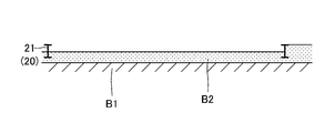
- FIG. 2 is a diagram showing a frame installation process of the installation method according to the first embodiment.
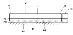
- FIG. 3 is a diagram showing a door body installation step of the installation method according to the first embodiment.
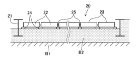
- FIG. 4 is a diagram showing one state of the panel arrangement process of the installation method according to the first embodiment.
- FIG. 5 is a plan view showing FIG. 4 as viewed from above.
- FIG. 6 is a diagram showing one state of the panel arrangement process of the installation method according to the first embodiment.
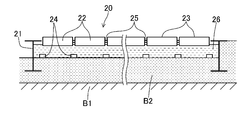
- FIG. 7 is a diagram showing a panel displacement process of the installation method according to the first embodiment.
- FIG. 8 is a diagram showing a schematic configuration of a spacing member according to a modified example of the first embodiment.
- FIG. 9 is a diagram showing a panel arrangement process of the installation method according to the second embodiment.
- FIG. 10 is a plan view showing FIG. 9 as viewed from above.
- FIG. 11 is a diagram showing a panel displacement process of the installation method according to the second embodiment.
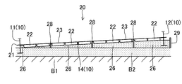
- FIG. 12 is a diagram showing a panel fixing step of the installation method according to the second embodiment.
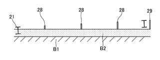
- FIG. 13 is a diagram showing a frame installation process and a partition process of the installation method according to the third embodiment.
- FIG. 14 is a diagram showing one state of the panel arrangement process of the installation method according to the third embodiment.
- FIG. 15 is a diagram showing one state of the panel arrangement process of the installation method according to the third embodiment.
- FIG. 16 is a diagram showing a panel displacement process of the installation method according to the third embodiment.
- FIG. 17 is a diagram showing a panel arrangement process of the installation method according to the fourth embodiment.
- FIG. 18 is a diagram showing a panel displacement process of the installation method according to the fourth embodiment.
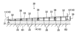
- FIG. 19 is a diagram showing a panel fixing step of the installation method according to the fourth embodiment.
- the undulating gate 1 of the present embodiment is installed on the road surface R (land) to prevent water from entering the living space or the underground space due to flood, tsunami, or heavy rain.
- the undulating gate 1 is a floating undulating gate (sometimes also referred to as a floating flap gate) that automatically performs an upright operation and an undulating operation by using water to enter.
- the undulating gate 1 includes a door body 10, a support portion 16, and a grounded portion 20.
- FIG. 1 schematically shows the grounded portion 20. Further, in FIG. 1, water is assumed to enter from the left side.
- the door body 10 is formed into a substantially rectangular body.
- the door body 10 rotates about the base end 12 side to stand up and lie down.
- the base end 12 of the door body 10 is rotatably supported by the support portion 16, and the door body 10 rotates from the laid-down state so that the tip 11 side stands up. That is, in the undulation gate 1, as shown by an arrow in FIG. 1, the undulation operation is performed by rotating clockwise, and the undulation operation is performed by rotating counterclockwise.
- the door body 10 is normally in a laid-down state (the state shown by the solid line in FIG. 1), and in an emergency (that is, when water has infiltrated), the door body 10 is rotated from the laid-down state by the buoyancy of the infiltrated water. It is configured to be in an upright state (the state shown by the alternate long and short dash line in FIG. 1).
- the door body 10 and the support portion 16 are provided in the storage portion S.
- the storage portion S is a recess formed in the road surface R, and the door body 10 is stored when the door body 10 is laid down.
- the lower surface 14 (grounding portion, grounding surface) of the door body 10 is grounded with the grounded surface 23 of the grounded portion 20, which will be described later.
- the upper surface 13 of the door body 10 is flush with the road surface R (that is, the same height. The same applies thereafter). That is, in a normal state, a vehicle or a person passing through the road surface R will pass through the upper surface 13 of the door body 10.
- the grounded portion 20 is provided at the bottom of the storage portion S, and is a portion where the door body 10 touches the ground when lying down. As shown in FIG. 7, the grounded portion 20 includes a frame 21, a panel 22, a raising member 24, an interval holding member 25, and a curing agent 26.
- the frame 21 is formed in a rectangular shape in a plan view.
- the size of the frame 21 in a plan view is substantially the same as the size of the lower surface 14 of the door body 10.
- a part (substantially lower half) of the frame 21 is embedded in the secondary concrete B2. That is, a part (substantially the upper half) of the frame 21 is exposed from the secondary concrete B2.
- the secondary concrete B2 is cast on the foundation concrete B1 located at the bottom of the storage portion S.
- the frame 21 is a member that defines the ground contact height (falling position) of the door body 10, and the lower surface 14 of the door body 10 touches the ground when lying down.
- the frame 21 is a rectangular frame in a plan view, and is formed by connecting I (eye) shaped steels in a rectangular shape (see FIG. 5). At the time of lodging, of the lower surface 14 of the door body 10, the lower surface 14 of the tip 11, the base end 12, and the widthwise end is in contact with the upper surface of the frame 21.
- the frame 21 may be formed of a shaped steel other than the I-shaped steel.
- a plurality of panels 22 are provided inside the frame 21, and form a grounded surface 23 to which the lower surface 14 of the door body 10 touches the ground when lying down.
- the panel 22 is formed in a rectangular shape having a certain thickness.
- the panel 22 is, for example, a PUF (hard urethane foam) panel.
- the plurality of panels 22 are arranged in a plane (horizontal plane) at intervals from each other. The upper surface of the plurality of panels 22 arranged in this way becomes the ground contact surface 23.
- the panel 22 may be made of a material other than the PUF panel.
- a plurality of raising members 24 are provided so that when the curing agent 26 is poured around the panel 22, a space is formed below the panel 22.
- the raising member 24 is provided under the panel 22 when the curing agent 26 is poured.
- the space-holding member 25 is a member that is attached between the panels 22 and 22 and holds the space between the panels 22.
- the space holding member 25 is provided at the center of one side of the panel 22.
- the spacing member 25 is configured to allow displacement of the panel 22 in the panel displacement process described later. That is, the interval holding member 25 is configured to follow the displacement of the panel 22 described above.
- the interval holding member 25 is, for example, a sponge member.
- the curing agent 26 fixes the panel 22 after being displaced by the panel displacement process.
- the curing agent 26 is provided around the panel 22 inside the frame 21.
- the curing agent 26 is poured into the frame 21 in a liquid state, and then cured to fix the panel 22.
- the specific density of the panel 22 is smaller than the specific gravity of the curing agent 26.
- the curing agent 26 is a cement-based self-leveling material or the like having high fluidity.
- the above-described undulating gate 1 installation method includes a frame installation process, a door body installation process, a panel arrangement process, a panel displacement process, and a panel fixing process.
- the frame installation step is a step of installing the frame 21 in the area where the door body 10 touches the ground at the bottom of the storage portion S. As shown in FIG. 2, in the frame installation process, the frame 21 is installed at a predetermined height from the foundation concrete B1.
- the frame 21 is temporarily fixed at a predetermined height position from the foundation concrete B1 and then fixed by the secondary concrete B2.
- the frame 21 is installed with a substantially lower half portion embedded in the secondary concrete B2 and a substantially upper half portion exposed from the secondary concrete B2.
- the method of installing the frame 21 is not limited to the above.
- the portion where the support portion 16 is installed is formed of the secondary concrete B2.
- the height of the secondary concrete B2 in the frame 21 is lower than the height of the secondary concrete B2 in which the support portion 16 is installed.
- the door body installation step is a step in which the door body 10 and the support portion 16 are installed in the storage portion S. Specifically, as shown in FIG. 3, the door body 10 and the support portion 16 are installed by fixing the support portion 16 to the secondary concrete B2. The base end 12 of the door body 10 is connected to the support portion 16. The door body 10 is installed in a state where the lower surface 14 can come into contact with the upper surface of the frame 21.
- the panel placement process is performed.
- the panel arranging step is performed with the door body 10 standing upright.
- the plurality of panels 22 are spaced apart from each other so that the panel 22 can be displaced along the lower surface 14 of the door body 10 by laying down the door body 10 and bringing it into contact with the lower surface 14 of the door body 10. This is a process of arranging in a plane.
- a plurality of raising members 24 are arranged at predetermined positions. That is, the raising member 24 is arranged on the secondary concrete B2 in the frame 21.
- a plurality of panels 22 are arranged on the raising member 24.
- the plurality of panels 22 are arranged with the interval holding member 25 attached between the panels 22 and the panel 22.
- the plurality of panels 22 are arranged in a plane (horizontal plane) at intervals from each other.
- the raising member 24 supports the four corners of the panel 22. In some places, one raising member 24 supports a plurality of corners. For example, at a position where the four corners of different panels 22 face each other, one raising member 24 is arranged so as to straddle the four corners. Further, at a position where two corners of different panels 22 are adjacent to each other, one raising member 24 is arranged so as to straddle the two corners.
- a liquid curing agent 26 is poured around the panel 22 to raise the panel 22. That is, the panel 22 is levitated by the buoyancy of the curing agent.
- the curing agent 26 is poured into the frame 21 until the panel 22 rises to a predetermined height. Specifically, the panel 22 rises to a position where the upper surface (contact patch 23) is higher than the upper surface of the frame 21, that is, until it projects upward from the upper surface of the frame 21.
- the buoyancy due to the curing agent 26 is more likely to act on the panel 22 as compared with the case where the panel is directly arranged on the secondary concrete B2, for example. .. Further, since the interval holding member 25 is provided, the interval between the panel 22 and the panel 22 is maintained, so that it is possible to prevent the panel 22 from being unevenly distributed in one place and floating.
- the panel 22 is in a displaceable state when the lower surface 14 of the door body 10 comes into contact with each other in the panel displacement step described later.
- the panel displacement step is a step in which the door body 10 is laid down so that the lower surface 14 of the door body 10 is brought into contact with the panel 22 and the panel 22 is displaced along the lower surface 14 of the door body 10.
- the panel displacement step is performed until the curing agent 26 is cured.
- the door body 10 is laid down until the lower surface 14 of the door body 10 comes into contact with the upper surface of the frame 21.
- the panel 22 protrudes from the upper surface of the frame 21, it comes into contact with the lower surface 14 of the door body 10 and is pushed down.
- the panel 22 is displaced along the shape of the lower surface 14 of the door body 10. Since the panel 22 is in a state of floating on the liquid curing agent 26, the panel 22 is easily displaced along the lower surface 14 of the door body 10. As a result, the gap between the lower surface 14 of the door body 10 and the grounded surface 23 (upper surface of the panel 22) is reduced.
- the panel 22 of the lower surface 14 where a positive error (distortion) is generated from the design value is displaced as compared with the panel 22 where a negative error (distortion) is generated from the design value.
- the amount is large. That is, there may be a case where the panel 22 does not come into contact with the portion where the negative error is larger than the design value. Therefore, the buoyancy height of the panel 22 due to the buoyancy of the curing agent 26, that is, the amount of protrusion from the upper surface of the frame 21 of the panel 22, takes into consideration the portion of the lower surface 14 of the door body 10 having the largest negative error than the design value. Is set.
- a positive error means that the lower surface 14 projects toward the arrow (+) side of the upper surface of the frame 21.
- a negative error means that the lower surface 14 is recessed on the arrow ( ⁇ ) side of the upper surface of the frame 21.
- the panel fixing step is a step of fixing the panel 22 displaced by the panel displacement step. That is, in the panel fixing step, the panel 22 is fixed in a displaced state. Specifically, as shown in FIG. 7, the door body 10 is continuously maintained in a state of being laid down from the panel displacement step. As a result, the panel 22 is maintained in a displaced state. Then, the panel 22 is fixed by curing the curing agent 26 after a lapse of a predetermined time.
- the method of installing the undulating gate 1 of the above embodiment includes a door body installation process, a panel arrangement process, a panel displacement process, and a panel fixing process.
- the door body installation step is a step of installing the door body 10.
- the panel arranging step the panel 22 is brought into contact with the lower surface 14 of the door body 10 by laying down the door body 10 and bringing a plurality of panels 22 forming a grounded surface 23 to which the lower surface 14 of the door body 10 touches the ground when the door body 10 is laid down.
- This is a step of arranging the door bodies 10 so as to be displaceable along the lower surface 14 of the door body 10 so as to be spaced apart from each other in a plane shape.
- the panel displacement step is a step in which the door body 10 is laid down, the lower surface 14 of the door body 10 is brought into contact with the panel 22, and the panel 22 is displaced along the lower surface 14 of the door body 10 after the panel arrangement step.
- the panel fixing step is a step of fixing the panel 22 after the panel displacement step.
- the plurality of panels 22 forming the grounded surface 23 to which the door body 10 touches the ground when lying down are displaceably arranged along the lower surface 14 of the door body 10, so that the manufactured door body is manufactured.
- the grounded surface 23 can be formed along the shape of the lower surface 14 of 10. Therefore, it is possible to reduce the gap between the door body 10 and the contact patch 23 at the time of lying down by simple construction. As a result, the durability of the door body 10 is improved.
- the panel 22 is designed by arranging the panel 22 at a height displaceable along the lower surface 14 of the door body 10.
- the grounded surface 23 can be formed at a high value. This is the same even when the secondary concrete B2 is placed higher than the design value. In this way, the contact patch 23 can be formed at a predetermined height regardless of the height of the secondary concrete B2.
- a liquid curing agent 26 is poured around the panel 22 to raise the panel 22 and to float the panel 22. Then, the panel 22 is fixed by curing the curing agent 26.
- the panel 22 since the panel 22 is floated by the curing agent 26, the panel 22 can be easily displaced along the lower surface 14 of the door body 10. Further, since the panel 22 is fixed by curing the curing agent 26, the panel 22 can be easily fixed.
- a spacing member 25 configured to allow displacement of the panel 22 in the panel displacement process is attached between the panel 22 and the panel 22.
- a raising member 24 for raising the panel 22 is arranged so that a space is formed below the panel 22, and a plurality of raising members 24 are placed on the raising member 24.
- Panel 22 is arranged.
- the buoyancy due to the curing agent 26 is more likely to act on the panel 22 than, for example, when the panel is directly arranged on the secondary concrete B2. Therefore, the panel 22 can be quickly levitated.
- the time required to displace the panel 22 is shortened by rapidly ascending the panel 22. be able to.
- the undulating gate 1 of the above embodiment includes a door body 10 and a grounded portion 20.
- the door body 10 rotates about the base end 12 side to stand up and lie down.
- the grounded portions 20 are arranged in a plane shape at intervals from each other, and are provided around a plurality of panels 22 and panels 22 that form a grounded surface 23 on which the lower surface 14 of the door body 10 touches the ground when lying down. It has a liquid curing agent 26 for fixing the above.
- the panel 22 can be displaced along the lower surface 14 of the door body 10 by bringing the lower surface 14 of the door body 10 into contact with the panel 22 floated by the liquid curing agent 26. be. Therefore, the contact patch 23 can be formed along the shape of the lower surface 14 of the door body 10, and the gap between the door body 10 and the contact patch 23 at the time of lying down can be reduced.
- the interval holding member 27 of this modified example is provided so as to project downward from the lower surface of the panel 22, and also serves as a raising member for raising the panel 22.
- the spacing member 27 is attached to the lower part of the panel 22. According to this configuration, the arrangement quantity of the raising member 24 can be reduced. Therefore, the time of the panel arrangement process can be shortened.
- the grounded portion 30 of the present embodiment includes a frame 31, a panel 32, a plastic member 34, and a curing agent 36.
- the raising member and the spacing member are omitted, while the plastic member 34 is added to the grounded portion 30.
- the frame 31 is a rectangular frame in a plan view that defines the ground contact height (falling position) of the door body 10, and the lower surface 14 of the door body 10 touches the ground when lying down.
- a plurality of panels 32 are provided inside the frame 31, and form a grounded surface 33 to which the lower surface 14 of the door body 10 touches the ground when lying down.
- the plurality of panels 32 are arranged in a plane (horizontal plane) at intervals from each other. The upper surface of the plurality of panels 32 arranged in this way becomes the ground contact surface 33.
- a plurality of plastic members 34 are arranged on the secondary concrete B2 inside the frame 31.
- the plastic member 34 is arranged below the panel 32 and plastically supports the panel 32.
- the plastic member 34 is configured to be plastically deformed with the displacement of the panel 32 in the panel displacement process.
- clay is used for the plastic member 34.
- the curing agent 36 fixes the panel 32 after being displaced by the panel displacement process.
- the curing agent 36 is provided around the panel 32 inside the frame 31.
- the curing agent 36 is poured into the frame 31 in a liquid state, and then cured to fix the panel 32.
- the method of installing the undulating gate 1 of the present embodiment includes a frame installation process, a door body installation process, a panel arrangement process, a panel displacement process, and a panel fixing process.
- the frame installation process and the door body installation process are performed in the same manner as in the first embodiment.
- the panel 32 is displaced along the lower surface 14 of the door body 10 by causing the door body 10 to lie down and bring it into contact with the lower surface 14 of the door body 10. It is a step of arranging them in a plane with a space between them.
- a plurality of plastic members 34 are arranged at predetermined positions. That is, the plastic member 34 is arranged on the secondary concrete B2 in the frame 31.
- a plurality of panels 32 are arranged on the plastic member 34.
- the plurality of panels 32 are arranged in a plane (horizontal plane) at intervals from each other. In this way, the panel 32 is supported by the plastic member 34. Further, the panel 32 is supported by the plastic member 34 so that the upper surface (contact patch 33) is higher than the upper surface of the frame 31, that is, protrudes upward from the upper surface of the frame 31.
- the plastic member 34 supports the four corners of the panel 32. In some places, one plastic member 34 supports a plurality of corners. For example, at a location where the four corners of different panels 32 face each other, one plastic member 34 is arranged across the four corners. Further, at a position where two corners of different panels 32 are adjacent to each other, one plastic member 34 is arranged so as to straddle the two corners.
- the panel displacement step is a step in which the door body 10 is laid down so that the lower surface 14 of the door body 10 is brought into contact with the panel 32, and the panel 32 is displaced along the lower surface 14 of the door body 10.
- the door body 10 is laid down until the lower surface 14 of the door body 10 comes into contact with the upper surface of the frame 31.
- the panel 32 protrudes from the upper surface of the frame 31, it comes into contact with the lower surface 14 of the door body 10 and is pushed down.
- the panel 32 is displaced along the shape of the lower surface 14 of the door body 10, and the plastic member 34 is plastically deformed with the displacement of the panel 32. That is, since the panel 32 is supported by the plastic member 34, it is easily displaced along the lower surface 14 of the door body 10. As a result, the gap between the lower surface 14 of the door body 10 and the grounded surface 33 (upper surface of the panel 32) is reduced.
- the amount of protrusion from the upper surface of the frame 31 of the panel 32 is set in consideration of the portion of the lower surface 14 of the door body 10 having the largest negative error than the design value. NS.
- the panel fixing step is a step of fixing the panel 32 displaced by the panel displacement step. That is, in the panel fixing step, the panel 32 is fixed in a displaced state.
- the door body 10 is erected. Subsequently, as shown in FIG. 12, a liquid curing agent 36 is poured around the panel 32, and after a predetermined time, the curing agent 36 cures to fix the panel 32 and the panel 32 does not float.
- the plastic member 34 is arranged, and a plurality of panels 32 are arranged on the plastic member 34.
- the plastic member 34 is displaced as the panel 32 is displaced. Plastic deformation. According to this configuration, since the panel 32 is supported by the plastic member 34, the panel 32 can be easily displaced along the lower surface 14 of the door body 10.
- the liquid curing agent 36 is poured around the panel 32, and the panel 32 is fixed by curing the curing agent 36. Therefore, the displaced panel 32 can be easily fixed. Can be done.
- Other configurations, actions and effects are the same as those in the first embodiment.
- the ground contact surface is formed in an inclined surface shape. That is, the grounded portion of the first embodiment is provided at the bottom of the storage portion formed on the horizontally extending road surface, and the grounded portion of the present embodiment is formed on the road surface inclined with respect to the horizontal. It is provided at the bottom of the storage unit.
- the points different from the above-described first embodiment will be described.
- the grounded portion 20 of the present embodiment includes a frame 21, a panel 22, an interval holding member (not shown), a curing agent 26, a partition plate 28, and an enclosure member 29. is doing.
- the frame 21 is provided so as to be inclined so that the upper surface is inclined according to the road surface (not shown).
- the position of the upper surface of the frame 21 increases toward the side corresponding to the base end 12 of the door body 10 at the time of lying down (on the right side in FIG. 16, hereinafter also referred to as one end side of the frame 21).
- the secondary concrete B2 is cast in a horizontal plane.
- the frame 21 may be provided so as to be inclined in the direction opposite to that of the present embodiment. That is, the position of the upper surface of the frame 21 may become higher toward the side corresponding to the tip 11 of the door body 10 at the time of lying down (the left side in FIG. 16, hereinafter also referred to as the other end side of the frame 21).
- a plurality of partition plates 28 are provided inside the frame 21, and the internal space of the frame 21 is partitioned in the inclined direction (horizontal direction in FIG. 16) of the frame 21. That is, the plurality of partition plates 28 are provided side by side in the inclined direction of the frame 21, and the inside of the frame 21 is partitioned into a plurality of spaces. The heights of the plurality of partition plates 28 are different from each other, and become higher as they approach one end side of the frame 21.
- the heights of the plurality of partition plates 28 are limited so that the lower surface 14 of the door body 10 and the partition plates 28 do not come into contact with each other when lying down.
- the plurality of partition plates 28 are provided so as to be located below the straight line connecting the upper surface on one end side and the upper surface on the other end side of the frame 21.
- a plurality of panels 22 are provided in each space partitioned by the partition plate 28. Similar to the first embodiment, the plurality of panels 22 provided in each space form a contact patch 23, and are arranged in a plane with a space between them. That is, the upper surface of the plurality of panels 22 constitutes a grounded surface 23 formed in an inclined surface shape that is inclined with respect to the horizontal.
- the curing agent 26 is provided around the panel 22 in each space partitioned by the partition plate 28.
- the curing agent 26 is poured into each space partitioned by the partition plate 28 in a liquid state, and then cured to fix the panel 22.
- the enclosure member 29 is provided on the outside of the frame 21 and regulates the flow region of the curing agent 26.
- the enclosure member 29 regulates the flow region of the curing agent 26 that has flowed out from between one end side of the frame 21 and the secondary concrete B2.
- the method of installing the undulating gate 1 of the present embodiment includes a frame installation process, a door body installation process, a panel arrangement process, a panel displacement process, and a panel fixing process, and further includes a partition process.
- the frame installation process is performed.
- the frame 21 is installed in a state of being tilted according to the slope of the road surface (not shown).
- a part of the other end side (left side in FIG. 13) of the frame 21 is embedded in the secondary concrete B2.
- One end side (right side in FIG. 13) of the frame 21 is installed at a distance from the secondary concrete B2. If the road surface has a gentle slope, one end side of the frame 21 may also be buried in the secondary concrete B2.
- the partitioning process is performed.
- a plurality of partitioning plates 28 are installed at predetermined positions inside the frame 21.
- the plurality of partition plates 28 are installed on the secondary concrete B2.
- the enclosure member 29 is installed outside the frame 21.
- the door body installation step is performed in the same manner as in the first embodiment.
- the door body installation step may be performed between the frame installation step and the partition step.
- a plurality of panels 22 are arranged in each space partitioned by the partition plate 28 in the frame 21.
- the panel 22 is arranged directly on the secondary concrete B2, but may be arranged on the raising member as in the first embodiment.
- a space-holding member is attached between the panel 22 and the panel 22 as in the first embodiment.
- a liquid curing agent 26 is poured around the panel 22 in each space partitioned by the partition plate 28 to raise the panel 22.
- the panel 22 in each space rises to a position where the upper surface (contact patch 23) is higher than the straight line connecting the upper surface on one end side and the upper surface on the other end side of the frame 21. That is, the levitation height of the panel 22 differs for each space.
- the door body 10 is laid down until the lower surface 14 of the door body 10 comes into contact with the upper surface of the frame 21. Then, the panel 22 comes into contact with the lower surface 14 of the door body 10 and is pushed down, and is displaced along the lower surface 14 of the door body 10. As a result, the gap between the lower surface 14 of the door body 10 and the grounded surface 23 (upper surface of the panel 22) is reduced.
- the panel 22 is fixed by curing the curing agent 26.
- the gap between the door body 10 and the contact patch 23 at the time of lodging can be reduced by a simple construction as in the first embodiment. Can be done.
- an inclined surface-like contact patch 23 can be easily formed.
- Other configurations, actions and effects are the same as those in the first embodiment.
- Embodiment 4 of the present application will be described with reference to FIGS. 17 to 19.
- the ground contact surface is formed in an inclined surface shape.
- the points different from the second embodiment will be described.
- the grounded portion 30 of the present embodiment includes a frame 31, a panel 32, a plastic member 35, a curing agent 36, a partition plate 38, and an enclosure member 39.
- the frame 31 is provided so as to be inclined so that the upper surface is inclined according to the road surface (not shown).
- the position of the upper surface of the frame 31 becomes higher toward the side corresponding to the base end 12 of the door body 10 at the time of lying down (on the right side in FIG. 19, hereinafter also referred to as one end side of the frame 31).
- the frame 31 may be provided so as to be inclined in the direction opposite to that of the present embodiment. That is, the position of the upper surface of the frame 31 may become higher toward the side corresponding to the tip 11 of the door body 10 at the time of lying down (the left side in FIG. 19, hereinafter also referred to as the other end side of the frame 31).
- a plurality of partition plates 38 are provided inside the frame 31, and the internal space of the frame 31 is partitioned in the inclined direction (horizontal direction in FIG. 19) of the frame 31. Further, the plurality of partition plates 38 are provided so as to be located below the straight line connecting the upper surface on one end side and the upper surface on the other end side of the frame 31, as in the third embodiment.
- a plurality of panels 32 are provided in each space partitioned by the partition plate 38. Similar to the first embodiment, the plurality of panels 32 provided in each space form a contact patch 33, and are arranged in a plane with a space between them. That is, the upper surface of the plurality of panels 32 constitutes a grounded surface 33 formed in an inclined surface shape that is inclined with respect to the horizontal.
- a plurality of plastic members 35 are arranged on the secondary concrete B2 in each space partitioned by the partition plate 38.
- the plastic member 35 is arranged under the panel 32 and plastically supports the panel 32, as in the second embodiment.
- the curing agent 36 is provided around the panel 32 in each space partitioned by the partition plate 38.
- the curing agent 36 is poured into each space partitioned by the partition plate 38 in a liquid state, and then cured to fix the panel 32.
- the enclosure member 39 regulates the flow region of the curing agent 36 that has flowed out from between one end side of the frame 31 and the secondary concrete B2.
- the method of installing the undulating gate 1 of the present embodiment includes a frame installation process, a door body installation process, a panel arrangement process, a panel displacement process, and a panel fixing process, and further includes a partition process, as in the first embodiment.
- the frame installation process, the partition process, and the door body installation process are performed in the same manner as in the third embodiment.
- a plurality of plastic members 35 are arranged in each space partitioned by the partition plate 38 in the frame 31.
- the plastic member 35 is higher as the plastic member 35 in the space closer to one end side (right side in FIG. 17) of the frame 31.
- a plurality of panels 32 are arranged on the plastic member 35.
- the plurality of panels 32 are arranged in a plane so as to be spaced from each other. Further, the panel 32 in each space is supported by the plastic member 35 so that the upper surface (contact patch 33) is higher than the straight line connecting the upper surface on one end side and the upper surface on the other end side of the frame 31. There is. That is, the arrangement height of the panel 32 is different for each space.
- the door body 10 is laid down until the lower surface 14 of the door body 10 comes into contact with the upper surface of the frame 31. Then, the panel 32 comes into contact with the lower surface 14 of the door body 10 and is pushed down, and is displaced along the lower surface 14 of the door body 10. At this time, the plastic member 35 is plastically deformed with the displacement of the panel 32. As a result, the gap between the lower surface 14 of the door body 10 and the grounded surface 33 (upper surface of the panel 32) is reduced.
- the door body 10 is first erected. Subsequently, as shown in FIG. 19, a liquid curing agent 36 is poured around the panel 32 in each space partitioned by the partition plate 38, and after a predetermined time, the curing agent 36 is cured to fix the panel 32. Will be done.
- the gap between the door body 10 and the contact patch 33 at the time of lodging can be reduced by a simple construction as in the first embodiment. Can be done.
- the inclined surface-shaped contact patch 33 can be easily formed.
- Other configurations, actions and effects are the same as those in the second embodiment.
- the frames 21 and 31 are installed as members that define the ground contact height (falling position) of the door body 10, but for example, in the width direction of the door body 10.
- the shape and size are not limited as long as the ground contact height of the door body 10 can be defined, such as installing the two members extending to the door body 10 on the tip end 11 side and the base end 12 side, respectively.
- a cover member may be provided around the curing agent so that the poured curing agent does not flow out, or the storage portion S itself may be used as a frame.
- the distance holding member 25 may be omitted.
- the raising member 24 may be omitted.
- the number of the partition plates 28 and 38 does not have to be a plurality, and may be one depending on the size of the door body 10 and the inclination angle of the door body 10 at the time of lying down. ..
- the technique disclosed in the present application is useful for the undulating gate and its installation method.
Landscapes
- Engineering & Computer Science (AREA)
- Structural Engineering (AREA)
- General Engineering & Computer Science (AREA)
- Mechanical Engineering (AREA)
- Civil Engineering (AREA)
- Barrages (AREA)
- Securing Of Glass Panes Or The Like (AREA)
- Gates (AREA)
- Refuge Islands, Traffic Blockers, Or Guard Fence (AREA)
Abstract
起伏ゲート1の設置方法は、扉体10を設置する扉体設置工程と、倒伏時に扉体10の下面14が接地する被接地面23を形成する複数のパネル22を、扉体10を倒伏させて扉体10の下面14と接触させることによってパネル22が扉体10の下面14に沿って変位可能に、互いに間隔を置いて平面状に配置するパネル配置工程と、パネル配置工程の後、扉体10を倒伏させて扉体10の下面14をパネル22に接触させ、パネル22を扉体10の下面14に沿って変位させるパネル変位工程と、パネル変位工程の後、パネル22を固定するパネル固定工程とを備えている。
Description
本願は、起伏ゲートおよびその設置方法に関する。
洪水や津波による浸水を防止するための起伏ゲート(フラップゲート)が例えば特許文献1に開示されている。この起伏ゲートは、支持部と、基端が支持部に回動自在に支持された扉体とを備えている。起伏ゲートでは、通常時は扉体が基礎地盤に接地して倒伏しており、非常時(浸水時)には扉体が回動して起立する。
ところで、倒伏時に扉体が接地する基礎地盤(被接地部)は、コンクリートで形成され、表面にある程度の凹凸が形成されるのが一般的である。一方、基礎地盤に接地する扉体の下面(接地部)も、コンクリート程ではないが、製缶誤差(歪み)がある。そうすると、倒伏時に扉体と基礎地盤との間に部分的な隙間が生じてしまい、扉体の上面に繰り返し作用する車両の輪荷重等によって扉体の耐久性が低下する。そのため、上述した隙間をできるだけ減らすために、基礎地盤の表面の凸部を削る等の作業が必要となり、非常に手間が掛かってしまう。
本願に開示の技術は、かかる事情に鑑みてなされたものであり、その目的は、簡易な施工により、倒伏時の扉体と被接地面との隙間を低減し得る起伏ゲートの設置方法および起伏ゲートを提供することにある。
本願に開示の技術は、基端側を中心に回動して起立および倒伏する扉体を備えた起伏ゲートの設置方法に係るものである。前記起伏ゲートの設置方法は、扉体設置工程と、パネル配置工程と、パネル変位工程と、パネル固定工程とを備えている。前記扉体設置工程は、前記扉体を設置する工程である。前記パネル配置工程は、倒伏時に前記扉体の下面が接地する被接地面を形成する複数のパネルを、前記扉体を倒伏させて前記扉体の下面と接触させることによって前記パネルが前記扉体の下面に沿って変位可能に、互いに間隔を置いて平面状に配置する工程である。前記パネル変位工程は、前記パネル配置工程の後、前記扉体を倒伏させて前記扉体の下面を前記パネルに接触させ、前記パネルを前記扉体の下面に沿って変位させる工程である。前記パネル固定工程は、前記パネル変位工程の後、前記パネルを固定する工程である。
本願に開示の別の技術は、扉体と、被接地部とを備えた起伏ゲートに係るものである。前記扉体は、基端側を中心に回動して起立および倒伏を行う。前記被接地部は、互いに間隔を置いて平面状に配置され、倒伏時に前記扉体の下面が接地する被接地面を形成する複数のパネル、前記パネルの周囲に設けられ、前記パネルを固定する液状の硬化剤を有している。
本願に開示の技術によれば、簡易な施工により、倒伏時の扉体と被接地面との隙間を低減することができる。
以下、本願の実施形態について図面を参照しながら説明する。なお、以下の実施形態は、本質的に好ましい例示であって、本願に開示の技術、その適用物、あるいはその用途の範囲を制限することを意図するものではない。
(実施形態1)
本願の実施形態1について図1~図7を参照しながら説明する。本実施形態の起伏ゲート1は、路面R(陸上)に設置され、洪水や津波、大雨によって水が生活空間や地下空間に浸入するのを防止するものである。起伏ゲート1は、浸入しようとする水を利用して自動的に起立動作および倒伏動作を行う浮体式起伏ゲート(浮体式のフラップゲートとも呼ばれることもある)である。
本願の実施形態1について図1~図7を参照しながら説明する。本実施形態の起伏ゲート1は、路面R(陸上)に設置され、洪水や津波、大雨によって水が生活空間や地下空間に浸入するのを防止するものである。起伏ゲート1は、浸入しようとする水を利用して自動的に起立動作および倒伏動作を行う浮体式起伏ゲート(浮体式のフラップゲートとも呼ばれることもある)である。
図1に示すように、起伏ゲート1は、扉体10と、支持部16と、被接地部20とを備えている。図1では、被接地部20を概略的に示している。また、図1において水は左側から浸入するものとする。
扉体10は、略矩形体に形成されている。扉体10は、基端12側を中心に回動して起立および倒伏する。扉体10は、基端12が支持部16に回動自在に支持されており、倒伏状態から回動して先端11側が起立する。即ち、起伏ゲート1では、図1に矢印で示すように、右回りに回動することで起立動作を行い、左回りに回動することで倒伏動作を行う。扉体10は、通常時は倒伏した状態(図1に実線で示す状態)になっており、非常時(即ち、水が浸入してきたとき)には浸入水の浮力によって倒伏状態から回動し起立した状態(図1に二点鎖線で示す状態)になるように構成されている。
扉体10および支持部16は、格納部Sに設けられている。格納部Sは、路面Rに形成された凹部であり、倒伏時に扉体10が格納される。扉体10が格納部Sに格納された状態、即ち扉体10が倒伏した状態では、扉体10の下面14(接地部、接地面)が後述する被接地部20の被接地面23と接地する一方、扉体10の上面13が路面Rと面一(即ち、同じ高さ。以降も同様。)となる。つまり、通常時は、路面Rを通行する車両や人は扉体10の上面13を通行することになる。
被接地部20は、格納部Sの底部に設けられ、倒伏時に扉体10が接地する部分である。図7にも示すように、被接地部20は、枠21と、パネル22と、嵩上げ部材24と、間隔保持部材25と、硬化剤26とを有している。
枠21は、平面視で矩形状に形成されている。枠21は、平面視の大きさが扉体10の下面14の大きさと略同じである。枠21は、一部(略下半部)が二次コンクリートB2に埋設されている。つまり、枠21は、一部(略上半部)が二次コンクリートB2から露出して設けられている。二次コンクリートB2は、格納部Sの底部に位置する基礎コンクリートB1の上に打設されている。
枠21は、扉体10の接地高さ(倒伏位置)を規定する部材であり、倒伏時に扉体10の下面14が接地する。枠21は、平面視矩形の枠であり、I(アイ)形鋼が矩形状に接続されて形成されている(図5参照)。倒伏時には、扉体10の下面14のうち、先端11、基端12および幅方向端部の下面14が枠21の上面に接地する。なお、枠21はI形鋼以外の形鋼で形成してもよい。
パネル22は、枠21の内側に複数設けられており、倒伏時に扉体10の下面14が接地する被接地面23を形成している。パネル22は、一定の厚さを有する矩形体状に形成されている。パネル22は、例えばPUF(硬質ウレタンフォーム)パネルである。複数のパネル22は、互いに間隔を置いて平面状(水平面状)に配置されている。こうして配置された複数のパネル22の上面が被接地面23となる。なお、パネル22は、PUFパネル以外の材質のものであってもよい。
嵩上げ部材24は、パネル22の周囲に硬化剤26を流し込む際、パネル22の下方に空間が形成されるように各パネル22を嵩上げするものであり、複数設けられている。嵩上げ部材24は、硬化剤26を流し込む際、パネル22の下に設けられる。
間隔保持部材25は、パネル22とパネル22との間に取り付けられ、パネル22同士の間隔を保持する部材である。間隔保持部材25は、パネル22の一辺の中央に設けられている。間隔保持部材25は、後述するパネル変位工程におけるパネル22の変位を許容可能に構成されている。つまり、間隔保持部材25は、上述したパネル22の変位に追従するように構成されている。間隔保持部材25は、例えばスポンジ部材である。
硬化剤26は、パネル変位工程による変位後のパネル22を固定するものである。硬化剤26は、枠21の内側においてパネル22の周囲に設けられている。硬化剤26は、液状態で枠21内に流し込まれ、その後硬化することによってパネル22を固定する。パネル22の比重は、硬化剤26の比重よりも小さい。硬化剤26は、流動性が高いセメント系セルフレベリング材等である。
〈起伏ゲートの設置方法〉
上述した起伏ゲート1の設置方法は、枠設置工程と、扉体設置工程と、パネル配置工程と、パネル変位工程と、パネル固定工程とを備えている。
上述した起伏ゲート1の設置方法は、枠設置工程と、扉体設置工程と、パネル配置工程と、パネル変位工程と、パネル固定工程とを備えている。
先ず、枠設置工程が行われる。枠設置工程は、格納部Sの底部において扉体10が接地する領域に枠21を設置する工程である。図2に示すように、枠設置工程では、枠21が基礎コンクリートB1から所定高さの位置に設置される。
具体的には、枠21は、基礎コンクリートB1から所定高さの位置に仮固定された後、二次コンクリートB2によって固定される。枠21は、略下半部が二次コンクリートB2に埋設され、略上半部が二次コンクリートB2から露出した状態で設置される。なお、枠21の設置方法は上述したものに限られない。
また、枠設置工程では、支持部16の設置される部分が二次コンクリートB2で形成される。枠21内における二次コンクリートB2の高さは、支持部16が設置される二次コンクリートB2の高さよりも低い。
枠設置工程に続いて、扉体設置工程が行われる。扉体設置工程は、扉体10および支持部16が格納部Sに設置される工程である。具体的に、図3に示すように、扉体10および支持部16は、支持部16が二次コンクリートB2に固定されることで設置される。扉体10は、基端12が支持部16に連結されている。扉体10は、下面14が枠21の上面に接触し得る状態で設置される。
扉体設置工程に続いて、パネル配置工程が行われる。パネル配置工程は、扉体10が起立した状態で行われる。パネル配置工程は、複数のパネル22を、扉体10を倒伏させて扉体10の下面14と接触させることによってパネル22が扉体10の下面14に沿って変位可能に、互いに間隔を置いて平面状に配置する工程である。
具体的には、図4および図5に示すように、パネル配置工程では、先ず、複数の嵩上げ部材24が所定の位置に配置される。つまり、嵩上げ部材24は、枠21内において二次コンクリートB2の上に配置される。
続いて、複数のパネル22が嵩上げ部材24の上に配置される。このとき、複数のパネル22は、パネル22とパネル22との間に間隔保持部材25が取り付けられた状態で配置される。複数のパネル22は、互いに間隔を置いて平面状(水平面状)に配置される。こうして、パネル22が嵩上げ部材24の上に配置されることで、パネル22の下方に空間が形成される。つまり、パネル22は、嵩上げ部材24によって支持されることで、二次コンクリートB2と間隔を置いて配置される。
嵩上げ部材24は、パネル22の4つの角部を支持している。箇所によっては、1つの嵩上げ部材24が複数の角部を支持している。例えば、異なるパネル22の4つの角部が互いに向き合う箇所では、1つの嵩上げ部材24がその4つの角部に跨って配置されている。また、異なるパネル22の2つの角部が隣り合う箇所では、1つの嵩上げ部材24がその2つの角部に跨って配置されている。
続いてパネル配置工程では、図6に示すように、パネル22の周囲に液状の硬化剤26を流し込んでパネル22を浮上させる。つまり、硬化剤の浮力によってパネル22を浮上させる。硬化剤26は、パネル22が所定の高さに浮上するまで枠21内に流し込まれる。具体的に、パネル22は、上面(被接地面23)が枠21の上面よりも高くなる位置まで、即ち枠21の上面よりも上方に突出するまで浮上する。
このとき、嵩上げ部材24によってパネル22の下方に空間が形成されているので、例えばパネルが二次コンクリートB2に直に配置される場合と比べて、硬化剤26による浮力がパネル22に作用しやすい。また、間隔保持部材25が設けられているので、パネル22とパネル22との間隔が保持され、そのため、パネル22が一カ所に偏在して浮上することを防止することができる。
こうしてパネル22を浮上させることにより、パネル22は、後述するパネル変位工程で扉体10の下面14が接触することによって変位可能な状態になる。
パネル配置工程に続いて、パネル変位工程が行われる。パネル変位工程は、扉体10を倒伏させて扉体10の下面14をパネル22に接触させ、パネル22を扉体10の下面14に沿って変位させる工程である。なお、パネル変位工程は、硬化剤26が硬化するまでに行われる。
具体的に、図7に示すように、扉体10の下面14が枠21の上面に接触するまで扉体10を倒伏させる。このとき、パネル22は、枠21の上面よりも突出しているため、扉体10の下面14と接触し押し下げられる。そうすると、パネル22は扉体10の下面14の形状に沿って変位する。パネル22は、液状の硬化剤26に浮いた状態であるため、容易に扉体10の下面14に沿って変位する。これにより、扉体10の下面14と被接地面23(パネル22の上面)との隙間が低減される。
例えば、下面14のうち設計値よりもプラスの誤差(歪)が発生している箇所のパネル22は、設計値よりもマイナスの誤差(歪)が発生している箇所のパネル22に比べて変位量が大きい。つまり、設計値よりもマイナスの誤差が大きい箇所ほど、パネル22と接触しない場合が生じ得る。そのため、硬化剤26の浮力によるパネル22の浮上高さ、即ちパネル22の枠21の上面からの突出量は、扉体10の下面14において設計値よりもマイナスの誤差が最も大きい箇所を考慮して設定される。
図7に示すように、例えば枠21の上面を設計値に相当する基準面とした場合、プラスの誤差とは、下面14が枠21の上面よりも矢印(+)側に突出していることを意味し、マイナスの誤差とは、下面14が枠21の上面よりも矢印(-)側に凹んでいることを意味する。
パネル変位工程に続いて、パネル固定工程が行われる。パネル固定工程は、パネル変位工程によって変位したパネル22を固定する工程である。つまり、パネル固定工程では、パネル22が変位した状態まま固定される。具体的には、図7に示すように、扉体10をパネル変位工程から引き続き倒伏させた状態で維持する。これにより、パネル22は変位した状態で維持される。そして、所定時間が経過し硬化剤26が硬化することによって、パネル22が固定される。
こうして、扉体10、支持部16および被接地部20の設置が完了する。
以上のように、上記実施形態の起伏ゲート1の設置方法は、扉体設置工程と、パネル配置工程と、パネル変位工程と、パネル固定工程とを備えている。扉体設置工程は、扉体10を設置する工程である。パネル配置工程は、倒伏時に扉体10の下面14が接地する被接地面23を形成する複数のパネル22を、扉体10を倒伏させて扉体10の下面14と接触させることによってパネル22が扉体10の下面14に沿って変位可能に、互いに間隔を置いて平面状に配置する工程である。パネル変位工程は、パネル配置工程の後、扉体10を倒伏させて扉体10の下面14をパネル22に接触させ、パネル22を扉体10の下面14に沿って変位させる工程である。パネル固定工程は、パネル変位工程の後、パネル22を固定する工程である。
上記の構成によれば、倒伏時に扉体10が接地する被接地面23を形成する複数のパネル22が、扉体10の下面14に沿って変位可能に配置されるため、製作された扉体10の下面14の形状に沿った被接地面23を形成することができる。したがって、簡易な施工により、倒伏時の扉体10と被接地面23との隙間を低減することができる。その結果、扉体10の耐久性が向上する。
また、例えば二次コンクリートB2が設計値よりも低い高さに打設された場合でも、パネル22が扉体10の下面14に沿って変位可能な高さにパネル22を配置することで、設計値の高さに被接地面23を形成することができる。これは、二次コンクリートB2が設計値よりも高く打設された場合でも同様である。このように、二次コンクリートB2の高さに左右されることなく、被接地面23を所定の高さに形成することができる。
また、上記実施形態の起伏ゲート1の設置方法において、パネル配置工程では、複数のパネル22を配置した後、パネル22の周囲に液状の硬化剤26を流し込んでパネル22を浮上させ、パネル固定工程では、硬化剤26が硬化することによってパネル22が固定される。
上記の構成によれば、パネル22を硬化剤26によって浮上させるため、簡易にパネル22を扉体10の下面14に沿って変位させることができる。また、硬化剤26が硬化することによってパネル22が固定されるので、簡易にパネル22を固定することができる。
また、上記実施形態の起伏ゲート1の設置方法において、パネル22とパネル22との間には、パネル変位工程におけるパネル22の変位を許容可能に構成された間隔保持部材25が取り付けられている。
上記の構成によれば、パネル22とパネル22との間隔が保持されるため、硬化剤26によってパネル22が浮上した際、パネル22が偏在して配置されることを防止することができる。そのため、扉体10の下面14の全体に対応した被接地面23を形成することができる。
また、上記実施形態の起伏ゲート1の設置方法において、パネル配置工程では、パネル22の下方に空間が形成されるようにパネル22を嵩上げする嵩上げ部材24を配置し、嵩上げ部材24の上に複数のパネル22を配置する。
上記の構成によれば、例えばパネルが二次コンクリートB2に直に配置される場合と比べて、硬化剤26による浮力がパネル22に作用しやすい。そのため、パネル22を速やかに浮上させることができる。上記実施形態では、硬化剤26が硬化するまでに扉体10を倒伏させてパネル22を変位させる必要があるところ、パネル22を速やかに浮上させることでパネル22を変位させるまでの時間を短縮することができる。特に、硬化するまでの時間が短い硬化剤を用いる場合や、扉体10の倒伏時間が懸かる場合には有効である。
また、上記実施形態の起伏ゲート1は、扉体10と、被接地部20とを備えている。扉体10は、基端12側を中心に回動して起立および倒伏する。被接地部20は、互いに間隔を置いて平面状に配置され、倒伏時に扉体10の下面14が接地する被接地面23を形成する複数のパネル22、パネル22の周囲に設けられ、パネル22を固定する液状の硬化剤26を有する。
上記の構成によれば、液状の硬化剤26によって浮上させたパネル22に、扉体10の下面14を接触させることによって、パネル22を扉体10の下面14に沿って変位させることが可能である。そのため、扉体10の下面14の形状に沿った被接地面23を形成することができ、倒伏時の扉体10と被接地面23との隙間を低減することができる。
(実施形態1の変形例)
本変形例は、上記実施形態1の起伏ゲート1の設置方法において、間隔保持部材の構成を変更するようにしたものである。ここでは、上記実施形態1と異なる点について説明する。
本変形例は、上記実施形態1の起伏ゲート1の設置方法において、間隔保持部材の構成を変更するようにしたものである。ここでは、上記実施形態1と異なる点について説明する。
図8に示すように、本変形例の間隔保持部材27は、パネル22の下面よりも下方に突出して設けられ、パネル22を嵩上げする嵩上げ部材を兼用している。間隔保持部材27は、パネル22の下部に取り付けられている。この構成によれば、嵩上げ部材24の配置数量を削減することができる。そのため、パネル配置工程の時間を短縮することができる。
(実施形態2)
本願の実施形態2について図9~図12を参照しながら説明する。本実施形態は、上記実施形態1において、パネル配置工程、パネル変位工程およびパネル固定工程の構成、並びに被接地部の構成を変更するようにしたものである。ここでは、上記実施形態1と異なる点について説明する。
本願の実施形態2について図9~図12を参照しながら説明する。本実施形態は、上記実施形態1において、パネル配置工程、パネル変位工程およびパネル固定工程の構成、並びに被接地部の構成を変更するようにしたものである。ここでは、上記実施形態1と異なる点について説明する。
本実施形態の被接地部30は、図12に示すように、枠31と、パネル32と、塑性部材34と、硬化剤36とを有している。被接地部30は、上記実施形態1の被接地部において、嵩上げ部材および間隔保持部材が省略される一方、塑性部材34が追加されたものである。
枠31は、上記実施形態1と同様、扉体10の接地高さ(倒伏位置)を規定する平面視矩形の枠であり、倒伏時に扉体10の下面14が接地する。パネル32は、上記実施形態1と同様、枠31の内側に複数設けられており、倒伏時に扉体10の下面14が接地する被接地面33を形成している。複数のパネル32は、互いに間隔を置いて平面状(水平面状)に配置されている。こうして配置された複数のパネル32の上面が被接地面33となる。
塑性部材34は、枠31の内側において二次コンクリートB2の上に複数配置されている。塑性部材34は、パネル32の下に配置され、パネル32を塑性的に支持している。塑性部材34は、パネル変位工程のパネル32の変位に伴って塑性変形するように構成されている。塑性部材34は、例えば粘土が用いられる。
硬化剤36は、パネル変位工程による変位後のパネル32を固定するものである。硬化剤36は、枠31の内側においてパネル32の周囲に設けられている。硬化剤36は、液状態で枠31内に流し込まれ、その後硬化することによってパネル32を固定する。
本実施形態の起伏ゲート1の設置方法は、上記実施形態1と同様、枠設置工程と、扉体設置工程と、パネル配置工程と、パネル変位工程と、パネル固定工程とを備えている。
先ず、枠設置工程および扉体設置工程が、上記実施形態1と同様に行われる。続くパネル配置工程は、上記実施形態1と同様、複数のパネル32を、扉体10を倒伏させて扉体10の下面14と接触させることによってパネル32が扉体10の下面14に沿って変位可能に、互いに間隔を置いて平面状に配置する工程である。
具体的には、図9および図10に示すように、パネル配置工程では、先ず、複数の塑性部材34が所定の位置に配置される。つまり、塑性部材34は、枠31内において二次コンクリートB2の上に配置される。
続いて、複数のパネル32が塑性部材34の上に配置される。複数のパネル32は、互いに間隔を置いて平面状(水平面状)に配置される。こうして、パネル32が塑性部材34によって支持される。また、パネル32は、上面(被接地面33)が枠31の上面よりも高くなるように、即ち枠31の上面よりも上方に突出するように塑性部材34で支持されている。
塑性部材34は、パネル32の4つの角部を支持している。箇所によっては、1つの塑性部材34が複数の角部を支持している。例えば、異なるパネル32の4つの角部が互いに向き合う箇所では、1つの塑性部材34がその4つの角部に跨って配置されている。また、異なるパネル32の2つの角部が隣り合う箇所では、1つの塑性部材34がその2つの角部に跨って配置されている。
パネル配置工程に続いて、パネル変位工程が行われる。パネル変位工程は、扉体10を倒伏させて扉体10の下面14をパネル32に接触させ、パネル32を扉体10の下面14に沿って変位させる工程である。
具体的に、図11に示すように、扉体10の下面14が枠31の上面に接触するまで扉体10を倒伏させる。このとき、パネル32は、枠31の上面よりも突出しているため、扉体10の下面14と接触し押し下げられる。そうすると、パネル32が扉体10の下面14の形状に沿って変位し、そのパネル32の変位に伴って塑性部材34が塑性変形する。つまり、パネル32は、塑性部材34によって支持されているため、容易に扉体10の下面14に沿って変位する。これにより、扉体10の下面14と被接地面33(パネル32の上面)との隙間が低減される。
本実施形態においても、上記実施形態1と同様、パネル32の枠31の上面からの突出量は、扉体10の下面14において設計値よりもマイナスの誤差が最も大きい箇所を考慮して設定される。
パネル変位工程に続いて、パネル固定工程が行われる。パネル固定工程は、パネル変位工程によって変位したパネル32を固定する工程である。つまり、パネル固定工程では、パネル32が変位した状態まま固定される。
具体的には、先ず、扉体10を起立させる。続いて、図12に示すように、パネル32の周囲に液状の硬化剤36を流し込み、所定時間の後、硬化剤36が硬化することによってパネル32が固定され、パネル32は浮上しない。
このように、本実施形態のパネル配置工程では、塑性部材34を配置し、塑性部材34の上に複数のパネル32を配置し、パネル変位工程では、塑性部材34がパネル32の変位に伴って塑性変形する。この構成によれば、パネル32が塑性部材34によって支持されるため、容易にパネル32を扉体10の下面14に沿って変位させることができる。
また、本実施形態のパネル固定工程では、パネル32の周囲に液状の硬化剤36を流し込み、硬化剤36が硬化することによってパネル32が固定されるので、変位したパネル32を簡易に固定することができる。その他の構成、作用および効果は、上記実施形態1と同様である。
(実施形態3)
本願の実施形態3について図13~図16を参照しながら説明する。本実施形態は、上記実施形態1が被接地面を水平面状に形成したのに代えて、被接地面を傾斜面状に形成するようにしたものである。つまり、上記実施形態1の被接地部は、水平に延びる路面に形成された格納部の底部に設けられるものであり、本実施形態の被接地部は、水平に対して傾斜した路面に形成された格納部の底部に設けられるものである。ここでは、上記実施形態1と異なる点について説明する。
本願の実施形態3について図13~図16を参照しながら説明する。本実施形態は、上記実施形態1が被接地面を水平面状に形成したのに代えて、被接地面を傾斜面状に形成するようにしたものである。つまり、上記実施形態1の被接地部は、水平に延びる路面に形成された格納部の底部に設けられるものであり、本実施形態の被接地部は、水平に対して傾斜した路面に形成された格納部の底部に設けられるものである。ここでは、上記実施形態1と異なる点について説明する。
図16に示すように、本実施形態の被接地部20は、枠21と、パネル22と、間隔保持部材(図示省略)と、硬化剤26と、仕切り板28と、囲い部材29とを有している。
枠21は、上面が路面(図示省略)に合わせて傾斜するように、傾いて設けられている。枠21の上面の位置は、倒伏時の扉体10の基端12に相当する側(図16において右側、以降、枠21の一端側ともいう)にいくに従って高くなっている。二次コンクリートB2は、水平面状に打設されている。
なお、枠21は、本実施形態とは逆方向に傾いて設けられていてもよい。即ち、枠21の上面の位置は、倒伏時の扉体10の先端11に相当する側(図16において左側、以降、枠21の他端側ともいう)にいくに従って高くなっていてもよい。
仕切り板28は、枠21の内側に複数設けられ、枠21の内部空間を枠21の傾斜方向(図16において左右方向)に仕切っている。つまり、複数の仕切り板28は、枠21の傾斜方向に並んで設けられ、枠21内を複数の空間に仕切っている。複数の仕切り板28の高さは、互いに異なっており、枠21の一端側に近づくにつれて高くなっている。
また、複数の仕切り板28の高さは、倒伏時の扉体10の下面14と仕切り板28とが接触しないように制限されている。具体的に、複数の仕切り板28は、枠21の一端側の上面と他端側の上面とを結んだ直線よりも下方に位置するように設けられている。
パネル22は、仕切り板28によって仕切られた各空間に複数設けられている。各空間に設けられた複数のパネル22は、上記実施形態1と同様、被接地面23を形成しており、互いに間隔を置いて平面状に配置されている。つまり、複数のパネル22の上面は、水平に対して傾斜する傾斜面状に形成された被接地面23を構成している。
硬化剤26は、仕切り板28によって仕切られた各空間においてパネル22の周囲に設けられている。硬化剤26は、仕切り板28によって仕切られた各空間に液状態で流し込まれ、その後硬化することによってパネル22を固定するものである。
囲い部材29は、枠21の外側に設けられ、硬化剤26の流動領域を規制するものである。本実施形態では、囲い部材29は、枠21の一端側と二次コンクリートB2との間から流出した硬化剤26の流動領域を規制している。
本実施形態の起伏ゲート1の設置方法は、上記実施形態1と同様、枠設置工程、扉体設置工程、パネル配置工程、パネル変位工程およびパネル固定工程を備え、さらに仕切り工程を備えている。
先ず、枠設置工程が行われる。図13に示すように、枠設置工程では、枠21が、路面(図示省略)の傾斜に合わせて傾いた状態で設置される。枠21の他端側(図13において左側)は、一部が二次コンクリートB2に埋設されている。枠21の一端側(図13において右側)は、二次コンクリートB2と間隔を置いて設置される。なお、路面の傾斜が緩やかな場合、枠21の一端側も二次コンクリートB2に埋設され得る。
続いて、仕切り工程が行われる。仕切り工程では、図13に示すように、複数の仕切り板28が、枠21の内側の所定位置に設置される。複数の仕切り板28は、二次コンクリートB2の上に設置される。また、仕切り工程では、囲い部材29が、枠21の外側に設置される。続いて、扉体設置工程が、上記実施形態1と同様に行われる。なお、扉体設置工程は、枠設置工程と仕切り工程との間に行うようにしてもよい。
続くパネル配置工程では、図14に示すように、先ず、複数のパネル22が、枠21内における仕切り板28によって仕切られた各空間に配置される。本実施形態では、パネル22は、二次コンクリートB2の上に直に配置されるが、上記実施形態1と同様に嵩上げ部材の上に配置するようにしてもよい。図示しないが、パネル22とパネル22との間には、上記実施形態1と同様、間隔保持部材が取り付けられている。
続いてパネル配置工程では、図15に示すように、仕切り板28によって仕切られた各空間においてパネル22の周囲に液状の硬化剤26を流し込んでパネル22を浮上させる。各空間におけるパネル22は、上面(被接地面23)が、枠21の一端側の上面と他端側の上面とを結んだ直線よりも高くなる位置まで浮上する。つまり、パネル22の浮上高さは空間ごとに異なる。
続くパネル変位工程では、図16に示すように、扉体10の下面14が枠21の上面に接触するまで扉体10を倒伏させる。そうすると、パネル22は、扉体10の下面14と接触して押し下げられ、扉体10の下面14に沿って変位する。これにより、扉体10の下面14と被接地面23(パネル22の上面)との隙間が低減される。続くパネル固定工程では、硬化剤26が硬化することによって、パネル22が固定される。
このように、被接地面23が傾斜面状に形成される形態においても、上記実施形態1と同様、簡易な施工により、倒伏時の扉体10と被接地面23との隙間を低減することができる。
また、コンクリートで傾斜面を形成することは比較的難しいところ、上記の方法によれば、簡易に傾斜面状の被接地面23を形成することができる。その他の構成、作用および効果は、上記実施形態1と同様である。
(実施形態4)
本願の実施形態4について図17~図19を参照しながら説明する。本実施形態は、上記実施形態2が被接地面を水平面状に形成したのに代えて、被接地面を傾斜面状に形成するようにしたものである。ここでは、上記実施形態2と異なる点について説明する。
本願の実施形態4について図17~図19を参照しながら説明する。本実施形態は、上記実施形態2が被接地面を水平面状に形成したのに代えて、被接地面を傾斜面状に形成するようにしたものである。ここでは、上記実施形態2と異なる点について説明する。
図19に示すように、本実施形態の被接地部30は、枠31と、パネル32と、塑性部材35と、硬化剤36と、仕切り板38と、囲い部材39とを有している。
枠31は、上記実施形態3と同様、上面が路面(図示省略)に合わせて傾斜するように、傾いて設けられている。枠31の上面の位置は、倒伏時の扉体10の基端12に相当する側(図19において右側、以降、枠31の一端側ともいう)にいくに従って高くなっている。
なお、枠31は、本実施形態とは逆方向に傾いて設けられていてもよい。即ち、枠31の上面の位置は、倒伏時の扉体10の先端11に相当する側(図19において左側、以降、枠31の他端側ともいう)にいくに従って高くなっていてもよい。
仕切り板38は、上記実施形態3と同様、枠31の内側に複数設けられ、枠31の内部空間を枠31の傾斜方向(図19において左右方向)に仕切っている。また、複数の仕切り板38は、上記実施形態3と同様、枠31の一端側の上面と他端側の上面とを結んだ直線よりも下方に位置するように設けられている。
パネル32は、上記実施形態3と同様、仕切り板38によって仕切られた各空間に複数設けられている。各空間に設けられた複数のパネル32は、上記実施形態1と同様、被接地面33を形成しており、互いに間隔を置いて平面状に配置されている。つまり、複数のパネル32の上面は、水平に対して傾斜する傾斜面状に形成された被接地面33を構成している。
塑性部材35は、仕切り板38によって仕切られた各空間において二次コンクリートB2の上に複数配置されている。塑性部材35は、上記実施形態2と同様、パネル32の下に配置され、パネル32を塑性的に支持している。
硬化剤36は、仕切り板38によって仕切られた各空間においてパネル32の周囲に設けられている。硬化剤36は、仕切り板38によって仕切られた各空間に液状態で流し込まれ、その後硬化することによってパネル32を固定するものである。囲い部材39は、上記実施形態3と同様、枠31の一端側と二次コンクリートB2との間から流出した硬化剤36の流動領域を規制している。
本実施形態の起伏ゲート1の設置方法は、上記実施形態1と同様、枠設置工程、扉体設置工程、パネル配置工程、パネル変位工程およびパネル固定工程を備え、さらに仕切り工程を備えている。
先ず、枠設置工程、仕切り工程および扉体設置工程が、上記実施形態3と同様に行われる。
続くパネル配置工程では、図17に示すように、先ず、複数の塑性部材35が、枠31内における仕切り板38によって仕切られた各空間に配置される。塑性部材35は、枠31の一端側(図17において右側)に近い空間の塑性部材35ほど高くなっている。
続いて、仕切り板38によって仕切られた各空間において、複数のパネル32が塑性部材35の上に配置される。複数のパネル32は、互いに間隔を置いて平面状に配置される。また、各空間におけるパネル32は、上面(被接地面33)が、枠31の一端側の上面と他端側の上面とを結んだ直線よりも高くなるように、塑性部材35で支持されている。つまり、パネル32の配置高さは空間ごとに異なる。
続くパネル変位工程では、図18に示すように、扉体10の下面14が枠31の上面に接触するまで扉体10を倒伏させる。そうすると、パネル32は、扉体10の下面14と接触して押し下げられ、扉体10の下面14に沿って変位する。このとき、塑性部材35は、パネル32の変位に伴って塑性変形する。これにより、扉体10の下面14と被接地面33(パネル32の上面)との隙間が低減される。
続くパネル固定工程では、先ず、扉体10を起立させる。続いて、図19に示すように、仕切り板38によって仕切られた各空間においてパネル32の周囲に液状の硬化剤36を流し込み、所定時間の後、硬化剤36が硬化することによってパネル32が固定される。
このように、被接地面33が傾斜面状に形成される形態においても、上記実施形態1と同様、簡易な施工により、倒伏時の扉体10と被接地面33との隙間を低減することができる。
また、上記実施形態3と同様、上記の方法によれば、簡易に傾斜面状の被接地面33を形成することができる。その他の構成、作用および効果は、上記実施形態2と同様である。
(その他の実施形態)
本願に開示の技術は、上記実施形態において以下のように構成するようにしてもよい。
本願に開示の技術は、上記実施形態において以下のように構成するようにしてもよい。
例えば、上記各実施形態では、扉体10の接地高さ(倒伏位置)を規定する部材として、枠21,31(枠状の部材)を設置するようにしたが、例えば扉体10の幅方向に延びる2本の部材をそれぞれ扉体10の先端11側と基端12側とに設置する等、扉体10の接地高さを規定し得るのであれば形状および大きさは問わない。その場合、流し込まれた硬化剤が流れ出ないように周囲にカバー部材を設けてもよいし、格納部S自体を枠として用いてもよい。
また、上記実施形態1および3において、硬化剤26の粘性等によってパネル22とパネル22との間隔がある程度保持されるのであれば、間隔保持部材25を省略するようにしてもよい。
また、上記実施形態1および3において、嵩上げ部材24は省略するようにしてもよい。
また、上記実施形態3および4において、仕切り板28,38の数量は、複数である必要はなく、扉体10の大きさや倒伏時の扉体10の傾斜角度によっては1枚であってもよい。
以上のように、本願に開示の技術は、起伏ゲートおよびその設置方法について有用である。
1 起伏ゲート
10 扉体
12 基端
14 下面
16 支持部
20 被接地部
22 パネル
23 被接地面
24 嵩上げ部材
25 間隔保持部材
26 硬化剤
27 間隔保持部材
30 被接地部
32 パネル
33 被接地面
34 塑性部材
35 塑性部材
36 硬化剤
10 扉体
12 基端
14 下面
16 支持部
20 被接地部
22 パネル
23 被接地面
24 嵩上げ部材
25 間隔保持部材
26 硬化剤
27 間隔保持部材
30 被接地部
32 パネル
33 被接地面
34 塑性部材
35 塑性部材
36 硬化剤
Claims (8)
- 基端側を中心に回動して起立および倒伏する扉体を備えた起伏ゲートの設置方法であって、
前記扉体を設置する扉体設置工程と、
倒伏時に前記扉体の下面が接地する被接地面を形成する複数のパネルを、前記扉体を倒伏させて前記扉体の下面と接触させることによって前記パネルが前記扉体の下面に沿って変位可能に、互いに間隔を置いて平面状に配置するパネル配置工程と、
前記パネル配置工程の後、前記扉体を倒伏させて前記扉体の下面を前記パネルに接触させ、前記パネルを前記扉体の下面に沿って変位させるパネル変位工程と、
前記パネル変位工程の後、前記パネルを固定するパネル固定工程とを備えている
ことを特徴とする起伏ゲートの設置方法。 - 請求項1に記載の起伏ゲートの設置方法において、
前記パネル配置工程では、前記複数のパネルを配置した後、前記パネルの周囲に液状の硬化剤を流し込んで前記パネルを浮上させ、
前記パネル固定工程では、前記硬化剤が硬化することによって前記パネルが固定される
ことを特徴とする起伏ゲートの設置方法。 - 請求項2に記載の起伏ゲートの設置方法において、
前記パネルとパネルとの間には、前記パネル変位工程における前記パネルの変位を許容可能に構成された間隔保持部材が取り付けられている
ことを特徴とする起伏ゲートの設置方法。 - 請求項2または3に記載の起伏ゲートの設置方法において、
前記パネル配置工程では、前記パネルの下方に空間が形成されるように前記パネルを嵩上げする嵩上げ部材を配置し、前記嵩上げ部材の上に前記複数のパネルを配置する
ことを特徴とする起伏ゲートの設置方法。 - 請求項3に記載の起伏ゲートの設置方法において、
前記間隔保持部材は、前記パネルの下面よりも下方に突出して設けられ、前記パネルを嵩上げする嵩上げ部材を兼用している
ことを特徴とする起伏ゲートの設置方法。 - 請求項1に記載の起伏ゲートの設置方法において、
前記パネル配置工程では、塑性部材を配置した後、前記塑性部材の上に前記複数のパネルを配置し、
前記パネル変位工程では、前記塑性部材が前記パネルの変位に伴って塑性変形する
ことを特徴とする起伏ゲートの設置方法。 - 請求項6に記載の起伏ゲートの設置方法において、
前記パネル固定工程では、前記パネルの周囲に液状の硬化剤を流し込み、前記硬化剤が硬化することによって前記パネルが固定される
ことを特徴とする起伏ゲートの設置方法。 - 基端側を中心に回動して起立および倒伏する扉体と、
互いに間隔を置いて平面状に配置され、倒伏時に前記扉体の下面が接地する被接地面を形成する複数のパネル、前記パネルの周囲に設けられ、前記パネルを固定する液状の硬化剤を有する被接地部とを備えている
ことを特徴とする起伏ゲート。
Applications Claiming Priority (2)
| Application Number | Priority Date | Filing Date | Title |
|---|---|---|---|
| JP2020-015221 | 2020-01-31 | ||
| JP2020015221A JP7520520B2 (ja) | 2020-01-31 | 2020-01-31 | 起伏ゲートおよびその設置方法 |
Publications (1)
| Publication Number | Publication Date |
|---|---|
| WO2021153005A1 true WO2021153005A1 (ja) | 2021-08-05 |
Family
ID=77078889
Family Applications (1)
| Application Number | Title | Priority Date | Filing Date |
|---|---|---|---|
| PCT/JP2020/045373 Ceased WO2021153005A1 (ja) | 2020-01-31 | 2020-12-07 | 起伏ゲートおよびその設置方法 |
Country Status (3)
| Country | Link |
|---|---|
| JP (1) | JP7520520B2 (ja) |
| TW (1) | TWI874557B (ja) |
| WO (1) | WO2021153005A1 (ja) |
Citations (4)
| Publication number | Priority date | Publication date | Assignee | Title |
|---|---|---|---|---|
| JP2013002250A (ja) * | 2011-06-21 | 2013-01-07 | Hitachi Zosen Corp | 浮体式フラップゲート |
| JP2013238092A (ja) * | 2012-05-17 | 2013-11-28 | Kaisei Kogyo Kk | 浮体式陸閘ゲート |
| WO2018070512A1 (ja) * | 2016-10-14 | 2018-04-19 | 日立造船株式会社 | 陸閘ゲート |
| JP2019196659A (ja) * | 2018-05-11 | 2019-11-14 | 日立造船株式会社 | 起伏ゲートおよびその設置方法 |
Family Cites Families (2)
| Publication number | Priority date | Publication date | Assignee | Title |
|---|---|---|---|---|
| JP3186520U (ja) * | 2013-07-30 | 2013-10-10 | 協同組合 土木設計センター | 駐車用パネル |
| JP6767916B2 (ja) * | 2017-04-05 | 2020-10-14 | 日立造船株式会社 | 起伏ゲート |
-
2020
- 2020-01-31 JP JP2020015221A patent/JP7520520B2/ja active Active
- 2020-12-07 WO PCT/JP2020/045373 patent/WO2021153005A1/ja not_active Ceased
-
2021
- 2021-01-13 TW TW110101288A patent/TWI874557B/zh active
Patent Citations (4)
| Publication number | Priority date | Publication date | Assignee | Title |
|---|---|---|---|---|
| JP2013002250A (ja) * | 2011-06-21 | 2013-01-07 | Hitachi Zosen Corp | 浮体式フラップゲート |
| JP2013238092A (ja) * | 2012-05-17 | 2013-11-28 | Kaisei Kogyo Kk | 浮体式陸閘ゲート |
| WO2018070512A1 (ja) * | 2016-10-14 | 2018-04-19 | 日立造船株式会社 | 陸閘ゲート |
| JP2019196659A (ja) * | 2018-05-11 | 2019-11-14 | 日立造船株式会社 | 起伏ゲートおよびその設置方法 |
Also Published As
| Publication number | Publication date |
|---|---|
| JP7520520B2 (ja) | 2024-07-23 |
| JP2021123845A (ja) | 2021-08-30 |
| TW202132659A (zh) | 2021-09-01 |
| TWI874557B (zh) | 2025-03-01 |
Similar Documents
| Publication | Publication Date | Title |
|---|---|---|
| CN111764521A (zh) | 一种用于停车楼结构的平板式变形缝结构及其制作方法 | |
| WO2021153005A1 (ja) | 起伏ゲートおよびその設置方法 | |
| CN103741561A (zh) | 轨道道床及其施工方法、高分子隔振支座更换方法 | |
| JP2003233640A (ja) | 建築物の構造計算装置、コンピュータプログラム、記録媒体及び建築物 | |
| CN204385578U (zh) | 一种建于填海区的建筑 | |
| JP3587761B2 (ja) | コンクリートブロックの設置法 | |
| CN210657992U (zh) | 一种用于改扩建桥梁临时护栏固定的装置 | |
| CN209687497U (zh) | 一种巷道支护构件 | |
| JP7232482B1 (ja) | プレキャストブロックの横引き敷設装置及び敷設方法 | |
| JP7116586B2 (ja) | 起伏ゲートの設置方法 | |
| CN217027183U (zh) | 一种水平标高可调的预制混凝土基础结构 | |
| CN222107548U (zh) | 一种组合式预制电缆沟构件 | |
| CN217307225U (zh) | 一种可周转集成式围挡结构 | |
| JP2981815B2 (ja) | コンクリートブロックの施工法 | |
| CN222782114U (zh) | 基于既有基础的附加设备安装结构 | |
| CN212865488U (zh) | 一种临时路面结构 | |
| CN222975889U (zh) | 一种用于深基坑的混凝土支撑梁柱 | |
| CN204258060U (zh) | 一种基于方形和三角形拼接板的易于定位的配电柜组件 | |
| CN217896096U (zh) | 一种紧邻桥墩的公路路基结构 | |
| CN111648398B (zh) | 一种gis设备模块化装配式混凝土工字形基础及其安装方法 | |
| JP3563662B2 (ja) | コンクリートブロック | |
| CN219060035U (zh) | 一种抗浮锚杆预应力传递装置 | |
| JP3574351B2 (ja) | 大型コンクリートブロックの設置用ヤジロベー支承体 | |
| CN204243543U (zh) | 一种基于三角形拼接板的易于定位的配电柜组件 | |
| JP3623877B2 (ja) | 大型コンクリートブロックの設置用上下調節装置 |
Legal Events
| Date | Code | Title | Description |
|---|---|---|---|
| 121 | Ep: the epo has been informed by wipo that ep was designated in this application |
Ref document number: 20916442 Country of ref document: EP Kind code of ref document: A1 |
|
| NENP | Non-entry into the national phase |
Ref country code: DE |
|
| 122 | Ep: pct application non-entry in european phase |
Ref document number: 20916442 Country of ref document: EP Kind code of ref document: A1 |