WO2021149772A1 - 磁気歯車の磁極片装置、磁気歯車、及び、磁気歯車の磁極片装置の製造方法 - Google Patents
磁気歯車の磁極片装置、磁気歯車、及び、磁気歯車の磁極片装置の製造方法 Download PDFInfo
- Publication number
- WO2021149772A1 WO2021149772A1 PCT/JP2021/002065 JP2021002065W WO2021149772A1 WO 2021149772 A1 WO2021149772 A1 WO 2021149772A1 JP 2021002065 W JP2021002065 W JP 2021002065W WO 2021149772 A1 WO2021149772 A1 WO 2021149772A1
- Authority
- WO
- WIPO (PCT)
- Prior art keywords
- pole piece
- cover member
- magnetic pole
- magnetic
- piece device
- Prior art date
- Legal status (The legal status is an assumption and is not a legal conclusion. Google has not performed a legal analysis and makes no representation as to the accuracy of the status listed.)
- Ceased
Links
Images














Classifications
-
- H—ELECTRICITY
- H02—GENERATION; CONVERSION OR DISTRIBUTION OF ELECTRIC POWER
- H02K—DYNAMO-ELECTRIC MACHINES
- H02K49/00—Dynamo-electric clutches; Dynamo-electric brakes
- H02K49/10—Dynamo-electric clutches; Dynamo-electric brakes of the permanent-magnet type
- H02K49/102—Magnetic gearings, i.e. assembly of gears, linear or rotary, by which motion is magnetically transferred without physical contact
-
- B—PERFORMING OPERATIONS; TRANSPORTING
- B32—LAYERED PRODUCTS
- B32B—LAYERED PRODUCTS, i.e. PRODUCTS BUILT-UP OF STRATA OF FLAT OR NON-FLAT, e.g. CELLULAR OR HONEYCOMB, FORM
- B32B3/00—Layered products comprising a layer with external or internal discontinuities or unevennesses, or a layer of non-planar shape; Layered products comprising a layer having particular features of form
- B32B3/10—Layered products comprising a layer with external or internal discontinuities or unevennesses, or a layer of non-planar shape; Layered products comprising a layer having particular features of form characterised by a discontinuous layer, i.e. formed of separate pieces of material
- B32B3/18—Layered products comprising a layer with external or internal discontinuities or unevennesses, or a layer of non-planar shape; Layered products comprising a layer having particular features of form characterised by a discontinuous layer, i.e. formed of separate pieces of material characterised by an internal layer formed of separate pieces of material which are juxtaposed side-by-side
-
- B—PERFORMING OPERATIONS; TRANSPORTING
- B32—LAYERED PRODUCTS
- B32B—LAYERED PRODUCTS, i.e. PRODUCTS BUILT-UP OF STRATA OF FLAT OR NON-FLAT, e.g. CELLULAR OR HONEYCOMB, FORM
- B32B5/00—Layered products characterised by the non- homogeneity or physical structure, i.e. comprising a fibrous, filamentary, particulate or foam layer; Layered products characterised by having a layer differing constitutionally or physically in different parts
- B32B5/02—Layered products characterised by the non- homogeneity or physical structure, i.e. comprising a fibrous, filamentary, particulate or foam layer; Layered products characterised by having a layer differing constitutionally or physically in different parts characterised by structural features of a fibrous or filamentary layer
-
- B—PERFORMING OPERATIONS; TRANSPORTING
- B32—LAYERED PRODUCTS
- B32B—LAYERED PRODUCTS, i.e. PRODUCTS BUILT-UP OF STRATA OF FLAT OR NON-FLAT, e.g. CELLULAR OR HONEYCOMB, FORM
- B32B5/00—Layered products characterised by the non- homogeneity or physical structure, i.e. comprising a fibrous, filamentary, particulate or foam layer; Layered products characterised by having a layer differing constitutionally or physically in different parts
- B32B5/22—Layered products characterised by the non- homogeneity or physical structure, i.e. comprising a fibrous, filamentary, particulate or foam layer; Layered products characterised by having a layer differing constitutionally or physically in different parts characterised by the presence of two or more layers which are next to each other and are fibrous, filamentary, formed of particles or foamed
- B32B5/24—Layered products characterised by the non- homogeneity or physical structure, i.e. comprising a fibrous, filamentary, particulate or foam layer; Layered products characterised by having a layer differing constitutionally or physically in different parts characterised by the presence of two or more layers which are next to each other and are fibrous, filamentary, formed of particles or foamed one layer being a fibrous or filamentary layer
- B32B5/26—Layered products characterised by the non- homogeneity or physical structure, i.e. comprising a fibrous, filamentary, particulate or foam layer; Layered products characterised by having a layer differing constitutionally or physically in different parts characterised by the presence of two or more layers which are next to each other and are fibrous, filamentary, formed of particles or foamed one layer being a fibrous or filamentary layer another layer next to it also being fibrous or filamentary
-
- F—MECHANICAL ENGINEERING; LIGHTING; HEATING; WEAPONS; BLASTING
- F16—ENGINEERING ELEMENTS AND UNITS; GENERAL MEASURES FOR PRODUCING AND MAINTAINING EFFECTIVE FUNCTIONING OF MACHINES OR INSTALLATIONS; THERMAL INSULATION IN GENERAL
- F16H—GEARING
- F16H57/00—General details of gearing
- F16H57/04—Features relating to lubrication or cooling or heating
- F16H57/042—Guidance of lubricant
- F16H57/043—Guidance of lubricant within rotary parts, e.g. axial channels or radial openings in shafts
-
- H—ELECTRICITY
- H02—GENERATION; CONVERSION OR DISTRIBUTION OF ELECTRIC POWER
- H02K—DYNAMO-ELECTRIC MACHINES
- H02K1/00—Details of the magnetic circuit
- H02K1/06—Details of the magnetic circuit characterised by the shape, form or construction
- H02K1/22—Rotating parts of the magnetic circuit
- H02K1/27—Rotor cores with permanent magnets
- H02K1/2706—Inner rotors
- H02K1/272—Inner rotors the magnetisation axis of the magnets being perpendicular to the rotor axis
- H02K1/274—Inner rotors the magnetisation axis of the magnets being perpendicular to the rotor axis the rotor consisting of two or more circumferentially positioned magnets
-
- H—ELECTRICITY
- H02—GENERATION; CONVERSION OR DISTRIBUTION OF ELECTRIC POWER
- H02K—DYNAMO-ELECTRIC MACHINES
- H02K1/00—Details of the magnetic circuit
- H02K1/06—Details of the magnetic circuit characterised by the shape, form or construction
- H02K1/22—Rotating parts of the magnetic circuit
- H02K1/28—Means for mounting or fastening rotating magnetic parts on to, or to, the rotor structures
-
- B—PERFORMING OPERATIONS; TRANSPORTING
- B32—LAYERED PRODUCTS
- B32B—LAYERED PRODUCTS, i.e. PRODUCTS BUILT-UP OF STRATA OF FLAT OR NON-FLAT, e.g. CELLULAR OR HONEYCOMB, FORM
- B32B2250/00—Layers arrangement
- B32B2250/20—All layers being fibrous or filamentary
-
- B—PERFORMING OPERATIONS; TRANSPORTING
- B32—LAYERED PRODUCTS
- B32B—LAYERED PRODUCTS, i.e. PRODUCTS BUILT-UP OF STRATA OF FLAT OR NON-FLAT, e.g. CELLULAR OR HONEYCOMB, FORM
- B32B2260/00—Layered product comprising an impregnated, embedded, or bonded layer wherein the layer comprises an impregnation, embedding, or binder material
- B32B2260/02—Composition of the impregnated, bonded or embedded layer
- B32B2260/021—Fibrous or filamentary layer
- B32B2260/023—Two or more layers
-
- B—PERFORMING OPERATIONS; TRANSPORTING
- B32—LAYERED PRODUCTS
- B32B—LAYERED PRODUCTS, i.e. PRODUCTS BUILT-UP OF STRATA OF FLAT OR NON-FLAT, e.g. CELLULAR OR HONEYCOMB, FORM
- B32B2260/00—Layered product comprising an impregnated, embedded, or bonded layer wherein the layer comprises an impregnation, embedding, or binder material
- B32B2260/04—Impregnation, embedding, or binder material
- B32B2260/046—Synthetic resin
-
- B—PERFORMING OPERATIONS; TRANSPORTING
- B32—LAYERED PRODUCTS
- B32B—LAYERED PRODUCTS, i.e. PRODUCTS BUILT-UP OF STRATA OF FLAT OR NON-FLAT, e.g. CELLULAR OR HONEYCOMB, FORM
- B32B2262/00—Composition or structural features of fibres which form a fibrous or filamentary layer or are present as additives
- B32B2262/10—Inorganic fibres
- B32B2262/106—Carbon fibres, e.g. graphite fibres
-
- B—PERFORMING OPERATIONS; TRANSPORTING
- B32—LAYERED PRODUCTS
- B32B—LAYERED PRODUCTS, i.e. PRODUCTS BUILT-UP OF STRATA OF FLAT OR NON-FLAT, e.g. CELLULAR OR HONEYCOMB, FORM
- B32B2307/00—Properties of the layers or laminate
- B32B2307/20—Properties of the layers or laminate having particular electrical or magnetic properties, e.g. piezoelectric
- B32B2307/208—Magnetic, paramagnetic
Definitions
- the present disclosure relates to a magnetic pole piece device for magnetic gears, a magnetic gear, and a method for manufacturing a magnetic pole piece device for magnetic gears.
- the magnetic flux modulation type (harmonic type) magnetic gear is between the magnet field on the inner peripheral side and the magnet field on the outer peripheral side arranged concentrically (coaxially) and these two magnet fields.
- Each of the magnet pieces is arranged with a gap (air gap) provided therein, and is provided with a magnetic pole piece device having a plurality of magnetic pole pieces (pole pieces) and a plurality of non-magnetic materials alternately arranged in the circumferential direction (see Patent Document 1). ).
- the magnetic flux of the magnet possessed by the above two magnet fields is modulated by each of the above magnetic pole pieces to generate a harmonic magnetic flux, and the two magnet fields are synchronized with the harmonic magnetic flux.
- the magnetic flux modulation type magnetic gear works.
- the magnet field on the outer peripheral side is fixed to function as a stator, and the magnet field on the inner peripheral side is used as a high-speed rotor.
- the above magnetic pole piece device functions as a low speed rotor. Then, by rotating the high-speed rotor by the magnetomotive force of the coil, the low-speed rotor rotates according to the reduction ratio.
- the magnetic geared motor a type in which a permanent magnet is installed in a high-speed rotor and a stator, a type in which a permanent magnet is installed only in a high-speed rotor, and the like are known.
- rigidity is strengthened by providing a rod-shaped reinforcing member extending along the axial direction for each of a plurality of magnetic pole pieces arranged along the circumferential direction.
- a reinforcing member is provided so as to extend in the axial direction, and contributes to rigidity against a load acting along the radial direction such as an electromagnetic force acting between magnet fields and a centrifugal load. It's hard to do. If the magnetic pole piece device does not have sufficient rigidity not only in the axial direction but also in the radial direction, deformation may occur in the radial direction and interfere with the adjacent magnet field magnet.
- At least one embodiment of the present disclosure has been made in view of the above circumstances, and provides a magnetic gear pole piece device, a magnetic gear, and a method for manufacturing a magnetic pole piece device of a magnetic gear having excellent rigidity. With the goal.
- the magnetic gear magnetic pole piece device is used to solve the above problems.
- the outer peripheral cover member and the inner peripheral cover member which are coaxially arranged on the outer and inner sides of the magnetic gear in the radial direction and have a cylindrical shape, respectively,
- a magnetic pole piece formed by partitioning a cylindrical space formed between an inner peripheral surface of the outer peripheral cover member and an outer peripheral surface of the inner peripheral cover member by a wall member extending along the radial direction.
- the magnetic gear according to at least one embodiment of the present disclosure is used to solve the above problems.
- the magnetic pole piece device according to at least one embodiment of the present disclosure and The inner diameter side magnet field arranged on the inner peripheral side of the magnetic pole piece device, The outer diameter side magnet field arranged on the outer peripheral side of the magnetic pole piece device, To be equipped.
- the method for manufacturing a magnetic pole piece device for a magnetic gear is to solve the above problems.
- the outer peripheral cover member and the inner peripheral cover member which are coaxially arranged on the outer and inner sides of the magnetic gear in the radial direction and have a cylindrical shape, respectively,
- a magnetic pole piece formed by partitioning a cylindrical space formed between an inner peripheral surface of the outer peripheral cover member and an outer peripheral surface of the inner peripheral cover member by a wall member extending along the radial direction.
- a step of manufacturing a first intermediate molded product by integrally molding one of the outer peripheral cover member and the inner peripheral cover member with the wall member.
- a step of manufacturing the second intermediate molded product by inserting the magnetic pole piece into a recess formed between the adjacent wall members of the first intermediate molded product.
- a magnetic gear pole piece device it is possible to provide a magnetic gear pole piece device, a magnetic gear, and a method for manufacturing a magnetic pole piece device of a magnetic gear having excellent rigidity.
- FIG. 4A It is sectional drawing which follows the radial direction of the magnetic gear which concerns on one Embodiment of this invention. It is a partially enlarged view of the magnetic gear shown in FIG. It is sectional drawing along the axial direction of the magnetic gear which concerns on one Embodiment of this invention. It is a schematic diagram of the cross section along the radial direction of the magnetic pole piece device which concerns on one Embodiment of this disclosure. It is a figure which shows the thermal conductivity and tensile elastic modulus of PAN-based CFRP and pitch-based CFRP in comparison with metal. It is a schematic view of the cross section along the axial direction of the LL line of FIG. 4A. FIG.
- FIG. 5 is a schematic cross-sectional view showing the vicinity of the outer peripheral cover member and the inner peripheral cover member of FIG. 5 in an enlarged manner.
- This is a first modification of FIG. It is an enlarged view of the range M of FIG.
- This is a second modification of FIG.
- It is a schematic diagram of the cross section along the axial direction of the NN line of FIG.
- It is a flowchart which shows roughly the manufacturing method of the magnetic pole piece apparatus which concerns on one Embodiment of this disclosure.
- It is a flowchart which shows one Embodiment of the manufacturing method of FIG.
- It is a schematic diagram which shows schematic manufacturing process of the magnetic pole piece apparatus in each process of FIG.
- It is a schematic diagram which shows schematic manufacturing process of the magnetic pole piece apparatus in each process of FIG.
- FIG. 16A It is a schematic diagram which shows schematic manufacturing process of the magnetic pole piece apparatus in each process of FIG. It is a flowchart which shows the other embodiment of the manufacturing method of FIG. It is a schematic diagram which shows schematic manufacturing process of the magnetic pole piece apparatus in each process of FIG. It is a schematic diagram which shows schematic manufacturing process of the magnetic pole piece apparatus in each process of FIG. It is a schematic diagram which shows schematic manufacturing process of the magnetic pole piece apparatus in each process of FIG. It is an example of the perspective view which shows the structural example of the core material. It is another example of the perspective view which shows the structural example of a core material. It is another example of the perspective view which shows the structural example of a core material. It is a modification of FIG. 16A. It is another modification of FIG. 16A.
- FIG. 1 It is a perspective view which shows the structural example of the magnetic pole piece held in the magnetic pole piece holder. It is a schematic diagram which shows the structure at the connection part of a solid member and a magnetic pole piece holder in a magnetic pole piece device. It is a schematic diagram which shows one of the attachment examples to the outer cover member or the inner cover member of the solid member shown in FIG. It is a schematic diagram which shows the other attachment example to the outer cover member or the inner cover member of the solid member shown in FIG. It is a schematic diagram which shows the other mounting example of a solid member. This is an example of a vertical cross-sectional view of a connecting structure including a solid member and a rotor end plate along the axial direction. It is a top view which shows the connection structure of FIG.
- expressions such as “same”, “equal”, and “homogeneous” that indicate that things are in the same state not only represent exactly the same state, but also have tolerances or differences to the extent that the same function can be obtained. It shall also represent the existing state.
- the expression representing a shape such as a quadrangular shape or a cylindrical shape not only represents a shape such as a quadrangular shape or a cylindrical shape in a geometrically strict sense, but also an uneven portion or chamfering within a range where the same effect can be obtained.
- the shape including the part and the like shall also be represented.
- the expressions “equipped”, “equipped”, “equipped”, “included”, or “have” one component are not exclusive expressions that exclude the existence of other components.
- FIG. 1 is a schematic cross-sectional view of the magnetic gear 9 according to the embodiment of the present invention along the radial direction c.
- FIG. 2 is a partially enlarged view of a cross section of the magnetic gear 9 shown in FIG.
- FIG. 3 is a schematic cross-sectional view of the magnetic gear 9 according to the embodiment of the present invention along the axial direction b.
- the magnetic gear 9 is a device having a mechanism for transmitting torque in a non-contact manner by utilizing the attractive force and the repulsive force of the magnet.
- the magnetic gears 9 shown in FIGS. 1 to 3 are magnetic flux modulation type (harmonic type), and as shown in the figure, the outer diameter side magnet field magnet 5 having a cylindrical (annular; the same applies hereinafter) shape as a whole. (Outer rotor), inner diameter side magnet field magnet 7 (inner rotor) having a cylindrical or columnar shape as a whole, and magnetic flux piece device 1 (center rotor) having a cylindrical shape as a whole are coaxially arranged.
- the outer diameter side magnet field 5 is arranged on the outer side (outer diameter side) in the radial direction with respect to the inner diameter side magnet field 7.
- the magnetic pole piece device 1 is arranged between the outer diameter side magnet field 5 and the inner diameter side magnet field 7.
- the outer diameter side magnet field 5, the inner diameter side magnet field 7, and the magnetic pole piece device 1 are arranged concentrically.
- the outer diameter side magnet field 5 and the inner diameter side magnet field 7 are circumferential in a cross section (hereinafter, radial cross section) cut along the radial direction c of the magnetic gear 9. It has magnetic pole pairs (51, 71) such as a permanent magnet composed of a plurality of N poles and S poles arranged at equal intervals on the top.
- the outer diameter side magnet field 5 has a plurality of magnetic pole pairs 51 and a support member 52 that supports the plurality of magnetic pole pairs 51. Then, on the cylindrical inner peripheral surface of the outer diameter side magnet field 5, a plurality of magnetic pole pairs 51 are oriented in the radial direction c, and the north and south poles are alternately alternated along the circumferential direction.
- the inner diameter side magnet field 7 has a plurality of inner diameter magnetic pole pairs 71 and a columnar inner diameter support member 72 that supports the plurality of inner diameter magnetic pole pairs 71. Then, on the cylindrical outer peripheral surface of the inner diameter side magnet field 7, a plurality of inner diameter magnetic pole pairs 71 are installed along the circumferential direction a along the entire circumference thereof in the same manner as described above.
- the magnetic pole piece device 1 has a plurality of magnetic pole pieces 41 (pole pieces) arranged at intervals (equal intervals) from each other over the entire circumference in the circumferential direction a. Then, for example, when the inner diameter side magnet field 7 is rotated, the magnetic flux of the inner diameter side magnet field 7 is modulated by the magnetic pole piece 41 of the magnetic pole piece device 1, and the modulated magnetic field and the action of the outer diameter side magnet field 5 act. A rotational torque is generated in the magnetic flux piece device 1.
- the magnetic gear 9 constitutes a magnetic geared motor by being integrated with the motor. More specifically, in this magnetic geared motor, the outer diameter side magnet field 5 is a stator (fixer) in which a plurality of coils 6 (see FIG. 2) are installed, and the inner diameter side magnet is generated by the electromotive force of the coils 6.
- the reduction ratio is determined by the ratio of the number of pole pairs of the magnetic pole pairs 51 of the outer diameter side magnet field 5 to the number of pole pairs of the inner diameter magnetic pole pairs 71 of the inner diameter side magnet field 7. According to this, the magnetic pole piece device 1 (low speed rotor) rotates.
- the magnetic geared motor is supplied with a cooling medium D such as air or water in order to protect the above components from heat generated during operation.
- a cooling medium D such as air or water
- FIG. 3 cylindrical gaps between the inner diameter side magnet field 7 and the magnetic pole piece device 1 and between the outer diameter side magnet field 5 and the magnetic pole piece device 1, respectively. G is formed, and the cooling medium D is supplied to each of these cylindrical gaps G so as to flow from one end side to the other end side.
- the cooling medium D is similarly supplied to the gap formed between the outer diameter side magnet field 5 and the housing H located on the outer peripheral side thereof.
- a gas such as air may be supplied to the gap between the outer diameter side magnet field 5 and the housing H.
- a water cooling pipe is installed and cooling water or the like is circulated through the water cooling pipe. You may let me.
- the above-mentioned magnetic pole piece device 1 acts between the above-mentioned two magnet fields (5, 7) adjacent to each other on the inner peripheral side and the outer peripheral side. Since it receives a load that acts along the radial direction, such as an electromagnetic force or a centrifugal load, if sufficient rigidity is not sufficient, deformation occurs in the radial direction c, and the magnetic pole pairs of the above-mentioned magnet field magnets adjacent to each other in the radial direction c. There is a risk of interfering with (51, 71). Therefore, the above-mentioned magnetic pole piece device 1 was configured as follows.
- the magnetic gear 9 can also operate as a magnetic geared generator.
- the magnetic pole piece device 1 center rotor rotates as the inner diameter side magnet field 7 (inner rotor) rotates.
- the operation differs depending on whether the magnetic pole piece device 1 is a magnetic geared motor or a magnetic geared generator, but the structure of the device is the same.
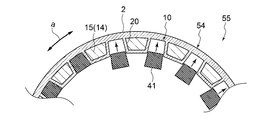
- FIG. 4A is a schematic cross-sectional view of the magnetic pole piece device 1 according to the embodiment of the present disclosure along the radial direction c.
- FIG. 4B is a diagram showing the thermal conductivity and tensile elastic modulus of PAN-based CFRP and pitch-based CFRP in comparison with metals (copper, aluminum, iron).
- FIG. 5 is a schematic cross-sectional view taken along the axial direction b of the LL line of FIG. 4A.
- the magnetic pole piece device 1 is a device (member) that constitutes a magnetic gear 9, such as a magnetic flux modulation type magnetic gear that constitutes a magnetic geared motor, and is a magnet field 7 (inner diameter side magnet field 7) in the magnetic gear 9. It is a device (member) arranged between the outer diameter side magnet field magnet 5 (stator in the case of a magnet geared motor) and the high-speed rotor in the case of a magnetic geared motor.
- the magnetic pole piece device 1 includes an outer peripheral cover member 2 arranged to face the inner peripheral surface of the outer diameter side magnet field 5 and an inner peripheral cover member arranged to face the outer peripheral surface of the inner diameter side magnet field 7. 3 and.
- the outer peripheral cover member 2 and the inner peripheral cover member 3 are members having a cylindrical shape as a whole. Further, the inner peripheral cover member 3 has a diameter smaller than that of the outer peripheral cover member 2, and is coaxially arranged inside the outer peripheral cover member 2.
- a cylindrical space 8 is formed over the entire circumference between the inner peripheral surface of the outer peripheral cover member 2 and the outer peripheral surface of the inner peripheral cover member 3 (in other words, the outer peripheral cover member 2 and the inner peripheral cover member 3 are formed. (Provided so as to sandwich the cylindrical space 8).
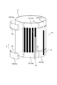
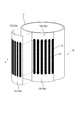
- a plurality of magnetic pole piece holders 10 are provided in the cylindrical space 8 by being partitioned by wall members 20 extending along the radial direction c.
- the plurality of magnetic pole piece holders 10 are arranged at predetermined intervals (for example, at equal intervals) along the circumferential direction.
- a long magnetic pole piece 41 (pole piece) is inserted into each of the magnetic pole piece holders 10 so that the longitudinal direction thereof is along the axial direction b.
- the wall member 20 constituting the magnetic pole piece holder 10 is integrally formed together with the outer peripheral cover member 2 and the inner peripheral cover member 3.
- the rigidity of the magnetic pole piece device 1 can be effectively improved.
- the magnetic gear 9 transmits power
- it is generated in the magnetic pole piece device 1 by a load along the radial direction such as an electromagnetic force or a centrifugal force received from the outer diameter side magnet field 5 or the inner diameter side magnet field 7.
- the rigidity against flexural deformation and torsional deformation can be effectively improved.
- the magnetic gear 9 transmits power
- the magnetic pole piece device 1 is deformed and comes into contact with the outer diameter side magnet field 5 and the inner diameter side magnet field 7 arranged through the gap G. You can effectively avoid the risk of losing.
- outer peripheral cover member 2, the inner peripheral cover member 3, and the wall member 20 that are integrally formed are integrally molded of, for example, carbon fiber reinforced plastic (CFRP: Carbon Fiber Reinforced Plastic).
- CFRP Carbon Fiber Reinforced Plastic
- the carbon fiber reinforced plastic is a lightweight material having excellent strength and reliability, and by using this, it is possible to secure excellent rigidity while suppressing an increase in the weight of the magnetic pole piece device 1.
- the pitch CFRP and the PAN CFRP may be combined depending on the application.
- the wall member 20 may include a pitch-based CFRP. Since the pitch-based CFRP is superior in thermal conductivity to the PAN-based CFRP, the wall member 20 adjacent to the magnetic pole piece 41 that generates heat during operation is composed of the pitch-based CFRP, and the fiber orientation thereof is oriented in the radial direction. By doing so, the heat dissipation function of the magnetic pole piece 41 can be effectively improved.
- the heat generated from the magnetic pole piece 41 is transferred to the inner and outer peripheral cover members (2, 3) via the wall member 20.
- heat can be efficiently dissipated and cooled from the air gap G provided on the inner and outer circumferences of the magnetic pole piece device 1.
- the fiber orientation of the outer peripheral cover member 2 and the inner peripheral cover member 3 may be a combination of fiber orientations intersecting the circumferential direction such as ⁇ 45 ° with respect to the circumferential direction and the axial direction.
- the torsional rigidity of the magnetic pole piece device 1 can be efficiently improved.
- the pitch-based CFRP has higher elasticity than the PAN-based CFRP, the deflection and torsional deformation of the magnetic pole piece device 1 situation due to the centrifugal load acting on the magnetic pole piece 41 and the torque load acting on the magnetic pole piece device 1 are efficiently performed. Can be suppressed.
- the CFRP carbon fibers used for the outer peripheral cover member 2, the inner peripheral cover member 3, and the wall member 20 are preferably fibers having an elastic modulus of 400 GPa, preferably 700 GPa or more.
- the higher the elastic modulus of carbon fiber the better the thermal conductivity.
- the thermal conductivity is twice that of iron
- the thermal conductivity is four times that of iron, which is equivalent to that of aluminum. Therefore, by using the carbon fiber having the elastic modulus, it is possible to achieve both the cooling property and the high rigidity of the magnetic pole piece device 1 at a higher level.
- the PAN-based CFRP has higher strength than the pitch-based CFRP. Therefore, PAN-based CFRP may be used for each member of the magnetic pole piece device 1 according to the strength required for the magnetic pole piece device 1.
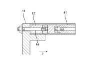
- a rotor end plate 11 for outputting the power transmitted to the magnetic pole piece device 1 is fixed to the end portion of the magnetic pole piece device 1 in the axial direction b.
- a solid member 12 is provided near the end of the cylindrical space 8 in the axial direction b.
- the solid member 12 is made of an insulating material such as the above-mentioned carbon fiber reinforced plastic or glass fiber reinforced plastic (GFRP: Grass Fiber Reinforced Plastic), and is formed of an inner peripheral surface of the outer peripheral cover member 2 and an inner peripheral cover member 3.
- the solid member 12 is the inner peripheral surface of the outer peripheral cover member 2 and the outer peripheral surface of the inner peripheral cover member 3. , And are configured to come into contact with the end faces of the rotor end plates 11).
- the connecting member 13 is embedded in the solid member 12.
- the connecting member 13 is, for example, a T-shaped bolt that has three ends threaded and is fastened to the outer peripheral cover member 2, the inner peripheral cover member 3, and the rotor end plate 11 to connect the three to each other. be.
- the magnetic pole piece 41 held by the magnetic pole piece holder 10 is firmly fixed, and good rigidity can be obtained with a stable structure.
- the plurality of magnetic pole piece holders 10 are arranged at predetermined intervals from each other along the circumferential direction a in the cylindrical space 8.
- An adjacent space 14 defined by a pair of wall members 20 is provided between adjacent magnetic pole piece holders 10 in the cylindrical space 8.
- the adjacent space 14 is filled by arranging the core material 15.
- the core material 15 is, for example, a polymer hard foam such as urethane, polyetherimide, polyimide, polymethacrylimide, or a polymer material alone or a composite of a polymer material and pulp fiber, aramid fiber, glass fiber, carbon fiber, or the like. It is composed of a lightweight non-magnetic material such as a honeycomb structure made of a material.
- the rigidity of the magnetic pole piece device 1 can be reduced even when the outer peripheral cover member 2 and the inner peripheral cover member 3 constituting the magnetic pole piece device 1 are thinned. It can be enhanced more effectively.
- FIG. 6 is a schematic cross-sectional view showing the vicinity of the outer peripheral cover member 2 and the inner peripheral cover member 3 of FIG. 5 in an enlarged manner.
- the outer peripheral cover member 2 includes a first layer 2a having a fiber direction in the first direction and a second layer 2b having a fiber direction in the second direction.
- the inner peripheral cover member 3 includes a first layer 3a having a fiber direction of the first direction and a second layer 3b having a fiber direction of the second direction.
- the first direction is a direction parallel to the circumferential direction a
- the second direction is a direction intersecting the circumferential direction a in the plane composed of the circumferential direction a and the axial direction b, for example, with respect to the axial direction b.
- the direction is ⁇ 45 degrees.
- the wall member 20 is a carbon fiber reinforced plastic whose fiber direction is a third direction or a fourth direction.
- the third direction is a direction parallel to the radial direction c
- the fourth direction is an axial direction b and a radial direction. It is a direction that intersects in the radial direction in the plane composed of c, for example, a direction that forms ⁇ 45 degrees with respect to the axial direction b.
- the outer peripheral cover member 2 and the inner peripheral cover member 3 having a hybrid structure in which a plurality of different layers are combined in this way, when the magnetic gear 9 transmits power, the outer diameter side magnet field 5 or the inner diameter side It is possible to effectively improve the rigidity against flexural deformation caused by the magnetic pole piece device 1 due to the load received from the magnet field 7 and the rigidity against torsional deformation due to torque transmission.
- centrifugal force acts on the magnetic pole piece device 1 along the radial direction c due to rotation, by arranging the first layer (2a, 3b) having the fiber direction in the first direction along the circumferential direction a.
- Centrifugal force in the radial direction c can be received as a hoop load by continuous carbon fibers having high rigidity and high strength, and bending deformation of the magnetic pole piece device 1 due to centrifugal force can be effectively suppressed.
- the magnetic pole piece device 1 needs to transmit the torque load from one end plate toward the other end plate, the second layer (2b) having the fiber direction in the second direction intersecting the circumferential direction a. By arranging 3b), the rigidity against twisting can be effectively improved.
- the first layer 2a of the outer peripheral cover member 2 is arranged on the inner peripheral side of the second layer 2b, but the first layer 2a is arranged on the outer peripheral side of the second layer 2b. May be good.
- the first layer 3a of the inner peripheral cover member 3 is arranged on the outer peripheral side of the second layer 3b, the first layer 3a may be arranged on the inner peripheral side of the second layer 3b.
- both the outer peripheral cover member 2 and the inner peripheral cover member 3 are composed of a plurality of layers (2a, 2b, 3a, 3b), but the outer peripheral cover member 2 or the inner peripheral circumference is shown. Only one of the cover members 3 may be composed of a plurality of layers.
- FIG. 7 is a first modification of FIG. 5, and FIG. 8 is an enlarged view of the range M of FIG.
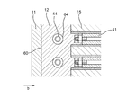
- the magnetic pole piece 41 held by the magnetic pole piece holder 10 includes a plurality of magnetic pole plate members 41a laminated along the axial direction b, as shown in FIG.
- Each of the plurality of magnetic pole plate members 41a has a hole portion 43 provided at a position corresponding to each other, and a fastening rod 44 extending along the axial direction b is inserted into the hole portion 43.
- the end portion of the fastening rod 44 is fastened to the above-mentioned solid member 12.
- the plurality of magnetic pole plate members 41a constituting the magnetic pole piece 41 are fixed to the rotor end plate 11 by the fastening rod 44 together with the outer peripheral cover member 2 and the inner peripheral cover member 3 via the solid member 12.
- the torsional rigidity of the magnetic pole piece device 1 is more effectively improved, the shear stress acting on the fastening bolt 13 and the bolt 14 is effectively reduced, and a larger torque can be transmitted. It will be possible.
- FIG. 9 is a second modification of FIG.
- FIG. 10 is a schematic view of a cross section taken along the axial direction b of the NN line of FIG.
- the above-mentioned adjacent space 14 defined by the pair of wall members 20 is configured as a hollow space (hollow core) between the adjacent magnetic pole piece holders 10 in the cylindrical space 8.
- the space 14 between adjacent spaces is not filled with the core material 15 as shown in FIG. 5).
- the outer peripheral cover member 2 and the inner peripheral cover member 3 that surround the adjacent space 14 are provided with cooling holes 17 that communicate with the outside.
- cooling holes 17 are provided in both the outer peripheral cover member 2 and the inner peripheral cover member 3.
- the cooling medium D (see FIG. 3) flowing through the gap G receives centrifugal force and is taken into the adjacent space 14 which is a hollow core from the cooling hole 17 provided in the inner peripheral cover member 3 inside.
- the cooling hole 17 may be provided in either the outer peripheral cover member 2 or the inner peripheral cover member 3.
- FIG. 11 is a flowchart schematically showing a manufacturing method of the magnetic pole piece device 1 according to the embodiment of the present disclosure.
- one of the outer peripheral cover member 2 or the inner peripheral cover member 3 constituting the magnetic pole piece device 1 and the wall member 20 are integrally formed to integrally form the first intermediate molded products 54, 54'(described later). (See FIG. 13 or FIG. 15) is manufactured (step S1).
- the magnetic pole piece device 1 is completed by attaching the other of the outer peripheral cover member 2 or the inner peripheral cover member 3 to the second intermediate molded products 55 and 55'and integrally molding the two (step S3).
- FIG. 12 is a flowchart showing an embodiment of the manufacturing method of FIG. 13A to 13C are schematic views schematically showing the manufacturing process of the magnetic pole piece device 1 in each process of FIG. 12.
- a molding die 50 corresponding to the first intermediate molded product 54 is prepared (step S100). That is, as shown in FIG. 13A, the surface shape of the molding die 50 on the outer side in the radial direction is configured to match the surface shape on the inner side in the radial direction of the first intermediate molded product 54. Specifically, on the radial outer surface of the molding die 50, a plurality of convex portions 50a are formed along the circumferential direction a so as to correspond to the radial inner surface shape of the first intermediate molded product 54 described later. It is provided.
- the molding die 50 has a built-in heater 59 that can be operated when heat treatment is performed later.
- the heater 59 includes, for example, a plurality of heating wires provided along the radial direction a.
- step S101 the constituent material of the first intermediate molded product 54 is laid on the molding mold 50 prepared in step S100 (step S101).
- the constituent material laid in step S101 is, for example, a prepreg material obtained by impregnating a fiber base material with the above-mentioned carbon fiber reinforced plastic or the like with a thermosetting resin.
- the first constituent material 60 corresponding to the wall member 20 is laid along the radial outer surface of the molding die 50.
- the non-magnetic material 62 corresponding to the core material 15 is inserted into the recess 61 on the radial outer surface of the first constituent material 60 (as shown in FIG. 9, the adjacent space 14 is filled with the core material 15).
- the second constituent material 63 corresponding to the outer peripheral cover member 2 is laid from the outside in the radial direction with respect to the first constituent material 60 into which the non-magnetic material 62 is inserted.
- step S102 the radial outer peripheral side of the constituent material laid on the molding die 50 is covered with the vacuum back 49 (step S102), and the rubber heater 53 is further installed on the radial outer peripheral side of the vacuum back 49 (step S103).
- step S104 the constituent materials laid on the molding die 50 are heated and cured.
- step S105 the first intermediate molded product 54 in which the outer peripheral cover member 2 and the magnetic pole piece holder 10 are integrally formed (cocure integrally molded) is completed (step S105).
- the magnetic pole piece 41 is inserted into the recess corresponding to the magnetic pole piece holder 10 in the first intermediate molded product 54 taken out from the molding die 50 (step S106), and the second intermediate molded product is formed. 55 is manufactured (step S107).
- the magnetic pole piece 41 inserted in step S106 is integrally molded together with the outer peripheral cover member 2 and the wall member 20 in steps S101 to S105.
- the constituent material 64 corresponding to the inner peripheral cover member 3 is laid on the surface of the second intermediate molded product 55 on the radial inner peripheral side (step S108).
- the constituent material 64 laid in step S108 is the same as the constituent material laid in step S101.
- a prepreg material obtained by impregnating a fiber base material with the above-mentioned carbon fiber reinforced plastic or the like with a thermosetting resin is used. ..
- the inner peripheral side in the radial direction of the constituent material laid in step S108 is covered with the vacuum back 56 (step S109), and the rubber heater 57 is further installed on the inner peripheral side of the vacuum back 56 (step S110).
- the rubber heater 57 arranged in step S110 is operated to heat the rubber heater 57 to perform the curing process (step S111).
- the inner peripheral cover member 3 is integrally molded with the second intermediate molded product 55 to complete the magnetic pole piece device 1.
- the inner peripheral cover member 3 is further integrally molded by using the second intermediate molded product 55 in which the magnetic pole piece 41 is inserted into the first intermediate molded product 54 as a substantially new molding mold. In addition to improving the shape accuracy of the product, extra processing and bonding processes are not required, which can improve productivity and reduce costs.
- step S108 cobond molding may be performed by interposing an adhesive between the second intermediate molded product 55 and laying the constituent material 64 corresponding to the inner peripheral cover member 3.
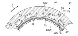
- FIG. 14 is a flowchart showing another embodiment of the manufacturing method of FIG. 15A to 15C are schematic views schematically showing the manufacturing process of the magnetic pole piece device 1 in each process of FIG. 14.
- a molding die 50'corresponding to the first intermediate molded product 54' is prepared (step S200). That is, as shown in FIG. 15A, the surface shape on the inner side in the radial direction of the molding die 50'is configured to match the surface shape on the outer side in the radial direction of the first intermediate molded product 54'. Specifically, on the radial inner surface of the molding die 50 ′, a plurality of convex portions 50a ′ are formed in the circumferential direction a so as to correspond to the radial outer surface shape of the first intermediate molded product 54 ′ described later. It is provided along.
- the molding die 50 ′ has a built-in heater 59 ′ that can be operated when heat treatment is performed later.
- the heater 59' includes, for example, a plurality of heating wires provided along the radial direction a.
- the constituent material of the first intermediate molded product 54' is laid on the molding mold 50'prepared in step S200 (step S201).
- the constituent material laid in step S201 is, for example, a prepreg material obtained by impregnating a fiber base material with the above-mentioned carbon fiber reinforced plastic or the like with a thermosetting resin.
- the first constituent material 60'corresponding to the wall member 20 is laid along the radial inner surface of the molding die 50'.
- the non-magnetic material 62'corresponding to the core material 15 is inserted into the recess 61'on the radial outer surface of the first constituent material 60'(as shown in FIG. 9, the core material is inserted into the adjacent space 14).
- the second constituent material 63'corresponding to the outer peripheral cover member 2 is laid from the inside in the radial direction with respect to the first constituent material 60'in which the non-magnetic material 62'is inserted.
- step S202 the inside of the constituent material laid on the molding die 50'in the radial direction is covered with a vacuum back 49'(step S202), and a rubber heater 53'is further installed inside the vacuum back 49'in the radial direction (step S203). ..
- a rubber heater 53' is further installed inside the vacuum back 49'in the radial direction.
- the magnetic pole piece 41 is inserted into the recess corresponding to the magnetic pole piece holder 10 in the first intermediate molded product 54'taken out from the molding die 50' (step S206), and the second intermediate is inserted.
- a molded product 55' is manufactured (step S207).
- the magnetic pole piece 41 inserted in step S206 is together with the inner peripheral cover member 3 and the wall member 20 in steps S201 to S205. It may be integrally molded. That is, in the second intermediate molded product 55, when the first intermediate molded product 54 is integrally molded, the inner peripheral cover member 3 is inserted into the wall member 20 constituting the magnetic pole piece holder 10 and the magnetic pole piece holder 10. Manufactured by integrally molding with 41. In this case, the magnetic pole piece device 1 can be manufactured more easily by integrally molding the magnetic pole piece 41 in addition to the inner peripheral cover member 3 and the wall member 20.
- the constituent material 64'corresponding to the outer peripheral cover member 2 is laid on the radial outer surface of the second intermediate molded product 55' (step S208).
- the constituent material 64 ′ laid in step S208 is the same as the constituent material laid in step S201, and for example, a prepreg material obtained by impregnating a fiber base material with a thermosetting resin with the above-mentioned carbon fiber reinforced plastic or the like is used. Be done.
- the radially outer side of the constituent material laid in step S208 is covered with a vacuum back 56'(step S209), and a rubber heater 57'is further installed on the outer peripheral side of the vacuum back 56' (step S210).
- step S210 the rubber heater 57'arranged in step S210 is operated to heat the rubber heater 57', thereby performing the curing process (step S211).
- step S211 the outer peripheral cover member 2 is integrally molded with the second intermediate molded product 55', and the magnetic pole piece device 1 is completed.
- the outer peripheral cover member 2 is formed. In addition to improving the shape accuracy of the product, extra processing and bonding processes are not required, which can improve productivity and reduce costs.
- step S208 cobond molding may be performed by interposing an adhesive between the second intermediate molded product 55'and laying the constituent material 64' corresponding to the outer peripheral cover member 2.
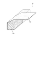
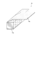
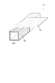
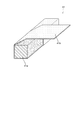
- 16A to 16C are perspective views showing a configuration example of the core material 15.
- the core material 15 includes a core body 15a and a first cover member 15b that at least partially surrounds the core body 15a.
- the first cover member 15b is provided so as to at least partially surround the core body 15a extending along the axial direction.
- the first cover member 15b is a single long member, and is wound around the core main body 15a over the entire circumference.
- the core body 15a is configured as a solid foam core.
- the foam core is a lightweight non-magnetic material as described above, for example, a polymer hard foam such as urethane, polyetherimide, polyimide, polymethacrylicimide, or a polymer material alone or a polymer material and pulp fiber, aramid fiber.
- a honeycomb structure or the like made of a composite material with glass fiber, carbon fiber or the like.
- the first cover member 15b is a fiber reinforced resin, for example, carbon fiber reinforced plastic (CFRP: Carbon Fiber Reinforced Plastic), glass fiber reinforced plastic (GFRP: Glass Fiber Reinforced Plastic), aramid fiber reinforced plastic (AFRP: Aramid Fiber Reinforce). , Basalt Fiber Reinforced Plastics (BFRP: Basalt Fiber Reinforced Plastics), Boron Fiber Reinforced Plastics (BFRP: Boron Fiber Reinforced Plastics), Keflar Fiber Reinforced Plastics (KFRP: Kevaler Fiber Reinforced Plastics) It is composed of Plastics) and the like.
- CFRP Carbon Fiber Reinforced Plastic
- GFRP Glass Fiber Reinforced Plastic
- AFRP Aramid Fiber Reinforce
- Basalt Fiber Reinforced Plastics Basalt Fiber Reinforced Plastics
- BFRP Basalt Fiber Reinforced Plastics
- Boron Fiber Reinforced Plastics BFRP: Boron Fiber Reinforced Plastics
- Keflar Fiber Reinforced Plastics Kevaler Fiber Reinforced Plastics
- the first cover member 15b is made of fiber reinforced plastic, a prepreg material in which a fiber base material is impregnated with a thermosetting resin is arranged around the core member 15a.
- the first cover member 15b is attached to the outer peripheral cover member 2 and the inner peripheral cover member 3 and is cured at the same time as the outer peripheral cover member 2 and the inner peripheral cover member 3, so that the first cover member 15b is attached to the outer peripheral cover member 2 and the inner peripheral cover member 2.
- It can be integrally configured with the peripheral cover member 3. As a result, good structural strength can be obtained, and in particular, weight reduction and workability during manufacturing can be expected while maintaining axial rigidity and torsional rigidity with respect to torque transmission.
- the first cover member 15b is divided with respect to each surface of the core main body 15a having a substantially quadrangular cross-sectional shape in a cross section perpendicular to the axial direction, and each surface.
- the first cover member 15b may be formed by being attached to the first cover member 15b.
- two cover members 15b1 and 15b2 having a substantially U-shape cover the core body 15a from both sides in a cross section perpendicular to the axial direction. It may be configured to be spliced as follows. In this case, as shown in FIG.
- the core body 15a is configured as a solid member made of fiber reinforced plastic.
- Fiber-reinforced plastics include, for example, Pitch-based and PAN-based carbon fibers, glass fibers, polymer fibers, etc., and resins such as epoxy, polyester, phenol, bismaleimide, polyurethane, and other thermocurable resins, thermoplastic resin polyimide, and PP.
- Polypropylene, Polyvinyl Chloride, Polyester, Polyetherimide, Nylon and other thermoplastic resins can be used.
- the first cover member 15b may be configured as, for example, a resin sheet containing a film adhesive.
- the core body 15a made of fiber reinforced plastic is formed by machining, for example, from a laminated plate.
- the outer cover member 2 and the inner cover member 3 are machined.
- the shape of the processed core body 15a can be suitably adapted to realize an integrated structure having good rigidity.
- the core body 15a is made of fiber reinforced plastic as in the embodiment shown in FIG. 16B, but has a hollow structure provided with a hollow portion 15a1 that opens in the axial direction. Have.
- the core body 15a having a hollow structure in this way, the weight of the magnetic pole piece device can be reduced. Further, by introducing a cooling medium into the hollow portion 15a1, it is possible to improve the cooling performance of the magnetic pole piece device 1.
- Such a hollow portion 15a1 can be easily formed by, for example, arranging a fiber reinforced resin prepreg around a core material having a shape corresponding to the hollow portion 15a1, performing a curing treatment, and then removing the core material. Is.
- the present embodiment illustrates the case where the cross-sectional shape of the hollow portion 15a1 is substantially rectangular, the cross-sectional shape of the hollow portion 15a may be any shape such as a circle or a polygon. Further, in the present embodiment, the case where the core main body 15a has one hollow portion 15a1 is illustrated, but a plurality of hollow portions 15a1 may be provided.
- FIG. 18 is a perspective view showing a configuration example of the magnetic pole piece 41 held by the magnetic pole piece holder 10.
- the magnetic pole piece 41 includes a magnetic pole piece main body 41a and a second cover member 41b that at least partially surrounds the magnetic pole piece main body 41a.
- the second cover member 41b may be provided so as to partially surround the magnetic pole piece main body 41a on a cross section orthogonal to the axial direction, or may be provided so as to surround the entire circumference of the magnetic pole piece main body 41a. May be good.
- the second cover member 41b is, for example, a film adhesive such as an epoxy resin or a fiber reinforced resin prepreg such as KFRP, and may be a combination thereof. As a result, the second cover member 41b is interposed between the h magnetic pole piece main body 41 and the outer cover member 2 or the inner cover member 3, so that the shear strength between the two can be effectively improved.
- the second cover member 41b may be configured as an elastic member such as a silicon sheet or a rubber sheet.
- the damping effect of the second cover member 41b can effectively attenuate the vibration generated in the magnetic pole piece device 1.
- the same effect can be expected when a Kevlar fiber reinforced prepreg having vibration damping characteristics is used as the second cover member 41b.
- the second cover member 41b may be configured as a foam sheet.
- the foam sheet has flexibility and the thickness can be adjusted, a gap generated between the two due to the dimensional tolerance when the magnetic pole piece 41 is assembled to the outer cover member 2 or the inner cover member 3.
- the magnetic pole piece device 1 can be easily assembled because it can be absorbed even when the magnet is filled or interference occurs. Further, even if a thermal expansion difference occurs between the magnetic pole piece 41 and the peripheral configuration even when heated during manufacturing or operation, it can be mitigated by the second cover member 41b, so that the interface peeling and the like can be effectively prevented. It can be avoided.
- FIG. 18 shows a case where a single second cover member 41b is wound around the magnetic pole piece main body 41a.
- the prepreg to be the second cover member 41b is wound around the magnetic pole piece main body 41a, then assembled to the outer cover member 2 and the inner cover member 3, and these are integrally cured to harden the second cover member 41b to the outside.
- the cover member 2 and the inner cover member 3 can be integrally formed with a good adhesive force, and the rigidity can be improved and the manufacturing process can be simplified.
- the second cover member 41b is attached by being cut so as to correspond to each surface of the magnetic pole piece main body 41a having a substantially quadrangular shape in a cross section perpendicular to the axial direction, following the above-mentioned first cover member 15b. It may be configured by being pasted in a substantially U shape (covering the remaining surfaces except one surface) and spliced.
- FIG. 19 is a schematic view showing a configuration at a connection portion between the solid member 12 and the magnetic pole piece holder 10 in the magnetic pole piece device 1.
- the solid member 12 is interposed between the end portion of the magnetic pole piece holder 10 in the axial direction b and the rotor end plate 11, so that the end portion of the magnetic pole piece holder 10 and the rotor end plate 11 are held together. It is a member for connecting.
- the solid member 12 has a substantially cylindrical shape, and the end portion 12a on the magnetic pole piece holder 10 side along the axial direction b is provided with a concave-convex shape 19 in which irregularities are alternately arranged along the circumferential direction. ..
- the concave-convex shape 19 has a shape complementary to the end of the magnetic pole piece holder 10 to be connected to the solid member 12. Specifically, the concave portion 19a1 of the concave-convex shape 19 corresponds to the core material 15 having a convex shape at the end of the magnetic pole piece holder 10, and the convex portion 19a2 has a magnetic pole piece 41 having a concave shape at the end of the magnetic pole piece holder 10. Corresponds to.
- Such a concave-convex shape 19 can facilitate the positioning performed when the solid member 12 is attached to the magnetic pole piece holder 10. This makes it possible to omit the jigs conventionally used for such positioning work.
- the concave-convex shape 19 can be formed by post-processing on the end portion 12a of the bulk-molded solid member 12.
- the uneven shape 19 can be formed with high accuracy by performing machining as post-processing. Since the solid member 12 has a substantially cylindrical shape, for example, when molding is performed, spring-in occurs during heat molding, which makes it difficult to maintain the accuracy of the radius of curvature. By doing so, good shape accuracy can be obtained.
- the solid member 12 having such an uneven shape 19 may be produced by using a 3D printer. In this case, since it is not necessary to perform curing molding or machining, high curvature accuracy can be obtained.
- the solid member 12 having such a configuration is attached to the outer cover member 2 or the inner cover member 3 by using, for example, an adhesive.
- 20A and 20B are schematic views showing an example of mounting the solid member 12 shown in FIG. 19 to the outer cover member 2 or the inner cover member 3.
- the solid member 12 is divided into a plurality of sub-members 12a, 12b, 12c, ... Along the circumferential direction, each of which is the outer cover member 2 or the inner cover member, respectively. It is attached to 3 using, for example, an adhesive.
- FIGS. 20A and 20B after the solid member 12 is attached to the inner cover member 3, the magnetic pole piece 41 and the core material 15 are attached to the solid member 12 fixed to the inner cover member 3. The situation is shown.
- the positioning accuracy of the magnetic pole piece 41 and the core material 15 to be attached later can be improved. This is advantageous in that good workability can be obtained even when the magnetic pole piece device 1 is large.
- the solid member 12 when the solid member 12 is attached to the inner cover member 3, a handling facility such as a crane is required when the magnetic pole piece device 1 is large, but if the solid member 12 is attached first by the handling facility, Since the remaining magnetic pole pieces 41 and the core material 15 are relatively lightweight, handling equipment is not required, and the work can be simplified.
- a handling facility such as a crane is required when the magnetic pole piece device 1 is large, but if the solid member 12 is attached first by the handling facility, Since the remaining magnetic pole pieces 41 and the core material 15 are relatively lightweight, handling equipment is not required, and the work can be simplified.
- FIG. 21 is a schematic view showing another mounting example of the solid member 12.
- the solid member 12, the magnetic pole piece 41, and the core material 15 are integrally attached to the inner cover member 3 with the magnetic pole piece 41 and the core material 15 attached in advance to the solid member 12. Can be attached to.
- the work can also be simplified by performing the mounting in this way.
- the fiber direction is set so that the coefficient of thermal expansion of these members is close to that of the magnetic pole piece 41. ..
- the fiber direction is set so that the coefficient of thermal expansion of these members is close to that of the magnetic pole piece 41. ..
- the fiber directions in the outer cover member 2, the inner cover member 3, and the wall member 20 may be set avoiding the axial direction b. Specifically, by setting the fiber direction to 90 ° with respect to the axial direction b, it is possible to effectively receive the centrifugal load and the electromagnetic force acting on the magnetic pole piece 41. Further, by setting the fiber direction to 45 ° with respect to the axial direction b, the torque load of the rotor can be received.
- FIG. 22A is an example of a vertical cross-sectional view of a connecting structure including the solid member 12 and the rotor end plate 11 along the axial direction b
- FIG. 22B is a plan view showing the connecting structure of FIG. 22A from the outside in the radial direction.
- the solid member 12 has a metal pad 62 provided on the end face 60 facing the rotor end plate 11 to be connected.
- a plurality of metal pads 62 are provided on the end surface 60 along the circumferential direction. These metal pads 62 are provided at positions that do not interfere with the fastening rod 44 described above.
- the distance between adjacent metal pads 62 is set to, for example, equal intervals.
- Each of the metal pads 62 has a substantially hemispherical shape and is formed from, for example, a metal material.
- FIG. 23A is another example of a vertical cross-sectional view of the connecting structure including the solid member 12 and the rotor end plate 11 along the axial direction b
- FIG. 23B is a plan view showing the connecting structure of FIG. 23A from the outside in the radial direction. be.
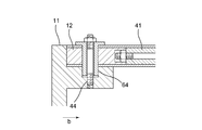
- the solid member 12 and the rotor end plate 11 are provided with a guide bush 64 provided along the connecting bolt 44.
- a guide bush 64 By providing such a guide bush 64, the shearing force generated in the fastening bolt 44 is received by the guide bush 64, and the shear failure of the fastening bolt 44 can be effectively prevented, so that the reliability can be improved.
- the guide bush 64 is provided substantially parallel to the axial direction b. As a result, by inserting the guide bush 64 into the hole 43 into which the fastening rod 44 is inserted, the guide bush 64 can be attached without further machining.
- the guide bush 64 is continuously provided over the solid member 12 and the rotor end plate 11. As a result, for example, when assembling the solid member 12 and the rotor end plate 11, the guide bush 64 is first attached to the solid member 12 side, and then, when the rotor end plate 11 is assembled, the guide bush 64 is used for positioning. Is possible, and the assembly dimensional accuracy can be effectively improved.
- FIG. 24A is another example of a vertical cross-sectional view of the connecting structure including the solid member 12 and the rotor end plate 11 along the axial direction b
- FIG. 24B is a plan view showing the connecting structure of FIG. 24A from the outside in the radial direction. be.
- the solid member 12 and the rotor end plate 11 are connected by providing the fastening bolt 44 perpendicularly to the axial direction b. Also in this case, by providing the guide bush 64 along the fastening bolt 44 according to the above-described embodiment, the guide bush 64 receives the shearing force generated in the fastening bolt 44, so that the shearing failure of the fastening bolt 44 is effective. In addition to being able to avoid this, positioning in the axial direction b is possible, and the assembly dimensional accuracy can be effectively improved.
- FIG. 25 is a perspective view showing another configuration example of the core material 15.
- the core material 15 may have a hollow structure having a hollow portion 15a1 extending along the axial direction b, as in the core main body 15a shown in FIG. 16C. In this case, good structural strength can be obtained while improving the cooling performance by circulating a cooling medium such as cooling air through the hollow portion 15a1.
- FIG. 26 is a schematic view showing the manufacturing process of the core material 15 shown in FIG. 25.
- a core material 70 having a substantially cylindrical shape extending along the axial direction b is prepared so as to correspond to the hollow portion 15a1.
- the prepreg 72 for forming the core material 15 is wound along the outer surface of the core material 70, and the core material 15 is formed by performing a hardening treatment.
- the core material 15 is completed by removing the core material from the molded core material 15 (pulling it out along the axial direction).
- a core material 15 having a hollow structure can be manufactured without machining.
- the cross-sectional shape of the hollow portion 15a1 may be any shape such as a polygon or a star. Further, in the present embodiment, the case where the core material 15 has one hollow portion 15a1 is illustrated, but a plurality of hollow portions 15a1 may be provided.
- the core material 70 may also be hardened together with the core material 15 by using a prepreg material. In this case, the core material 15 and the core material 70 are simultaneously cured, so that the molding process can be simplified.
- FIG. 27 is an example of a cross-sectional view perpendicular to the axial direction b of the core material 15.
- a damping member 74 for damping vibration may be provided on at least a part of the surface of the core material 15 facing the outer cover member 2 and the inner cover member 3 constituting the magnetic pole piece holder 10.
- the first damping member 74A is provided on the first surface 75A of the core material 15 facing the outer cover member 2
- the second damping member 74B is provided on the second surface 75B facing the inner cover member 3. Be done.
- vibration can be absorbed and good seismic performance can be obtained.
- the first damping member 74A is provided along the first surface 74A facing the outer cover member 2 which is easily affected by vibration, it is easy to obtain a damping action.
- FIG. 28 is a modified example of FIG. 27.
- the core material 15 may be divided into a plurality of plate-shaped members 76 along the thickness direction.
- the magnetic pole piece holder 10 By forming the magnetic pole piece holder 10 into a divided structure in this way, friction is generated between the plate-shaped members 76 when vibration is generated, so that vibration energy is converted into thermal energy and a good damping effect can be obtained.
- the third damping member 74C may be provided between the two adjacent plate-shaped members 76. By providing the third damping member 74C inside the core material 15 in this way, the vibration propagating inside can be absorbed while being repeatedly reflected between the damping members, and the damping effect can be expected to be improved.
- each of the above-mentioned damping members 74 is not limited, but for example, a polymer fiber reinforced composite material can be used. Since the polymer fiber reinforced composite material can be simultaneously cured with the outer cover member 2, the inner cover member 3, and the wall member made of fiber reinforced plastic, better structural strength can be obtained by integrally forming with these members. Can be obtained. Further, the damping member 74 may be formed of a resin-based highly elastic material. In this case, the elasticity of the damping member 74 absorbs the vibration, and the damping characteristic can be obtained more effectively.
- a sliding member may be arranged in place of or in addition to the third damping member 74C between the two adjacent plate-shaped members 76.
- a resin material such as Teflon (registered trademark) can be used, and it is possible to effectively prevent the divided members from being worn by friction.
- the natural frequency of the magnetic pole piece holder 10 may be adjusted by appropriately changing the division pattern.
- excellent damping characteristics can be obtained by setting the division pattern so that the natural frequency of the magnetic pole piece holder 10 is different from the vibration frequency generated in the magnetic pole piece holder 10.
- the division pattern is shown as an example in the case where the thickness is uniform in FIG. 28, but the thickness may be adjusted so that the required damping characteristic can be obtained, for example, the outside is fine and the inside is rough. good.
- FIG. 29 is another modification of FIG. 27.
- the core member 15 shown in FIG. 27 is divided into a first member 15-1 on the outer cover member 2 side and a second member 15-2 on the inner cover member 3 side.
- the damping characteristics can be improved by arranging the fourth damping member 74D also at the interface between the first member 15-1 and the second member 15-2.
- Such a core material 15 is formed by laminating the materials of the first member 15-1 and the second member 15-2, respectively, and then when assembling the two members, the first member 15-1 and the second member 15-
- the fourth damping member 74D is laminated and molded at the interface of 2.
- the fourth damping member 74D When an elastic adhesive is used as the fourth damping member 74D, the first member 15-1 and the second member 15-2 are each cured and molded, and then the fourth damping member 74D, which is an elastic adhesive, is formed at the interface between the first member 15-1 and the second member 15-2. May be arranged and both may be adhered to complete the core material 15. This can be expected to improve the internal quality of the magnetic pole piece holder 10.
- FIG. 30 is another modification of FIG. 27.
- a fifth damping member 74E is further provided along the hollow portion 15a1.
- Such a fifth damping member 74E can be arranged by winding the damping material around the outer surface of the core material 70 when the hollow portion 15a1 is formed by using the core material 70 as described above.
- a sixth damping member 74F may be provided on at least one outer surface of the outer cover member 2 or the inner cover member 3.
- FIG. 31A is a modification of FIG.
- the sixth damping member 74F is provided on at least a part of the outer surface (diameter outer surface) of the outer cover member 2 when viewed in a cross section perpendicular to the axial direction b.
- the sixth damping member 74F is widely provided along the outer surface of the outer cover member 2.
- the damping characteristics can be improved by providing the sixth damping member 74F in this way.
- the damping characteristics can be effectively improved by providing the sixth damping member 74F on the outer surface of the outer cover member 2 as in this modification. ..
- FIG. 31B is another modification of FIG. In this modification, in addition to the modification shown in FIG. 31A, the sixth damping member 74F is also provided on at least a part of the outer surface (diametrically inner surface) of the inner cover member 3. In this modification, the sixth damping member 74F is widely provided along the outer surface of the inner cover member 3. By providing the sixth damping member 74F on the outer surfaces of both the outer cover member 2 and the inner cover member 3 in this way, the damping characteristics of the magnetic pole piece device 1 can be further improved.
- Such a sixth damping member 74F may be formed from a material containing a fiber reinforced composite material such as a polymer fiber reinforced composite material. Since such a material can be simultaneously cured with the outer cover member 2 and the inner cover member 3 made of fiber reinforced plastic, the sixth damping member 74F is integrated with the outer cover member 2 and the inner cover member 3. This makes it possible to improve the damping characteristics while maintaining the structural strength.
- the sixth damping member 74F may be provided only on the outer surface of the inner cover member 3.
- FIG. 31C is another modification of FIG.
- the seventh damping member 74G is provided so as to at least partially surround the core material 15 when viewed in a cross section perpendicular to the axial direction b.
- the seventh damping member 74G is provided so as to surround the entire circumference of the core material 15.
- the damping characteristics can be improved by providing the seventh damping member 74G in this way.
- Such a seventh damping member 74G may be formed from a material containing a fiber reinforced composite material such as a polymer fiber reinforced composite material, as in the case of the sixth damping member 74F described above. Since such a material can be simultaneously cured with the outer cover member 2 and the inner cover member 3 made of fiber reinforced plastic, the seventh damping member 74G is integrated with the outer cover member 2 and the inner cover member 3. This makes it possible to improve the damping characteristics while maintaining the structural strength.
- a fiber reinforced composite material such as a polymer fiber reinforced composite material
- FIG. 31D is another modification of FIG.
- the sixth damping member 74F is provided on the outer surfaces of the outer cover member 2 and the inner cover member 3, respectively, and the seventh damping member 74G surrounds the core material 15, which is a combination of the above-mentioned modifications. It is provided as follows. By providing both the sixth damping member 74F and the seventh damping member 74G in this way, the damping characteristics can be further improved.
- the magnetic gear magnetic pole piece device is An outer peripheral cover member (for example, the outer peripheral cover member 2 of the above embodiment) and an inner peripheral cover member (for example, the outer peripheral cover member 2 of the above embodiment) which are coaxially arranged on the outer and inner sides of the magnetic gear (for example, the magnetic gear 9 of the above embodiment) and have a cylindrical shape, respectively.
- a magnetic pole piece holder (for example, the magnetic pole piece holder 10 of the above embodiment) formed by partitioning with a member (for example, the wall member 20 of the above embodiment) and A magnetic pole piece held in the magnetic pole piece holder (for example, the magnetic pole piece 41 of the above embodiment) and With The inner ring member, the outer ring member, and the wall member are integrally formed.
- the outer peripheral cover member and the inner peripheral cover member are connected to each other by a wall member extending in the radial direction, and by integrally forming these, a magnetic pole having excellent rigidity.
- One-sided device can be realized.
- the magnetic pole piece device is deformed, which effectively risks contacting the outer diameter side magnet field and the inner diameter side magnet field arranged through the gap. Can be avoided.
- the outer peripheral cover member and the inner peripheral cover member are connected members (for example, the connecting member 13 of the above embodiment) embedded in a solid member (for example, the solid member 12 of the above embodiment) arranged in the cylindrical space. Is fixed to the rotor end plate (for example, the rotor end plate 11 of the above embodiment) via.
- the outer peripheral cover member, the inner peripheral cover member and the rotor end plate are firmly fixed to each other via the connecting member embedded in the solid member, and a stable structure has good rigidity. can get.
- the solid member has a shape complementary to the end of the rotor end plate.
- the solid member since the solid member has a complementary shape to the end portion of the rotor end plate, the complementary shape is used when connecting the solid member to the rotor end plate. Both can be easily positioned.
- the solid member has at least one metal pad (for example, the metal pad 62 of the above embodiment) provided on the end face facing the rotor end plate.
- the solid member and the rotor end plate are provided with a guide bush (for example, the guide bush 64 of the above embodiment) provided along the connecting bolt.
- the shearing force generated in the fastening bolt is received by the guide bush, and the reliability can be improved by effectively preventing the shearing failure of the fastening bolt. ..
- the magnetic pole piece includes a plurality of magnetic pole plate materials (for example, the magnetic pole plate material 41a of the above embodiment) laminated along the axial direction.
- the plurality of magnetic pole plate materials are fixed to the solid member via a fastening rod (for example, the fastening rod 44 of the above embodiment) through which holes provided in each of the plurality of magnetic pole plates are inserted.
- a magnetic pole piece composed of a plurality of magnetic pole plate materials laminated along the axial direction is connected by a fastening rod together with an outer peripheral cover member and an inner peripheral cover member via a solid member. Can be fixed to the rotor end plate.
- the outer peripheral cover member, the inner peripheral cover member, and the wall member are each composed of carbon fiber reinforced plastic.
- the outer peripheral cover member, the inner peripheral cover member, and the wall member are integrally formed of carbon fiber reinforced plastic which is lightweight, has high strength, and has excellent moldability, so that good rigidity is obtained. It is possible to realize a magnetic pole piece device having.
- At least one of the outer peripheral cover member and the inner peripheral cover member has a fiber direction of a first layer (for example, the first layers 2a and 3a of the above embodiment) including a first direction in which the fiber direction is along the circumferential direction. It includes a second layer including a second direction intersecting the first direction (for example, the second layers 2b and 3b of the above embodiment).
- At least one of the outer peripheral cover member and the inner peripheral cover member is formed by combining a plurality of layers having different fiber directions from each other.
- the wall member is composed of pitch-based CFRP.
- the pitch-based CFRP is superior in thermal conductivity to the PAN-based CFRP
- the wall member adjacent to the magnetic pole piece that generates heat during operation is composed of the pitch-based CFRP.
- the heat dissipation function from the magnetic pole piece can be effectively improved.
- a core material for example, the core material 15 of the above embodiment
- the adjacent space for example, the adjacent space 14 of the above embodiment
- the rigidity of the magnetic pole piece device can be improved more effectively by filling the space between adjacent spaces with a core material.
- the core material is A core body (for example, the core body 15a of the above embodiment) and A first cover member (for example, the first cover member 15b of the above embodiment) that at least partially surrounds the core body and To be equipped.
- the core material includes a core body and a first cover member.
- Good structural strength can be obtained by surrounding the core body of the first cover member at least partially, and in particular, while maintaining axial rigidity and torsional rigidity with respect to torque transmission, weight reduction and workability during manufacturing are achieved. You can expect improvement.
- a damping member for damping vibration (for example, the damping member 74 of the above embodiment) is provided on at least a part of the core material facing the outer cover member or the inner cover member.
- the magnetic pole piece device by providing the magnetic pole piece device with a damping member, vibration generated during operation can be absorbed and good seismic performance can be obtained.
- a damping member (for example, the sixth damping member 74F of the above embodiment) is provided so as to cover at least one outer surface of the outer cover member or the inner cover member.
- the damping characteristics of the magnetic pole piece device can be improved by covering at least a part of the outer surface of the outer cover member 2 or the inner cover member 3 with a damping member. Further, in particular, the damping characteristics can be effectively improved by providing the damping member on the outer surface of the outer cover member in response to the fact that the strain tends to be large on the outer side in the radial direction during vibration.
- a damping member (for example, the seventh damping member 74G of the above embodiment) is provided so as to surround the core material at least partially.
- the damping characteristics of the magnetic pole piece device can be improved by providing the damping member so as to surround the entire circumference of the core material. Further, for example, when the damping member is made of a fiber reinforced composite material, the damping member can be cured at the same time as the outer cover member and the inner cover member. Therefore, the damping member is integrated with the outer cover member and the inner cover member to form a structure. It is possible to improve the damping characteristics while maintaining the strength.
- the adjacent space formed between the adjacent magnetic pole piece holders (for example, the adjacent space 14 of the above embodiment) is formed as a hollow core.
- the hollow core communicates with the outside through a cooling hole (for example, the cooling hole 17 of the above embodiment) opened along the radial direction in at least one of the outer peripheral cover member or the inner peripheral cover member.
- cooling medium it is preferable to guide the cooling medium to the adjacent space formed as the hollow core through the cooling holes provided in at least one of the outer peripheral cover member and the inner peripheral cover member. Cooling effect can be obtained.
- the magnetic pole piece is With the magnetic pole piece main body (for example, the magnetic pole piece main body 41a of the above embodiment), A second cover member (for example, the second cover member 41b of the above embodiment) that at least partially surrounds the magnetic pole piece main body and To be equipped.
- a second cover member for example, the second cover member 41b of the above embodiment
- the magnetic pole piece is configured to include a magnetic pole piece main body and a second cover member.
- Good structural strength can be obtained by surrounding the magnetic pole piece body at least partially in the second cover member, and in particular, weight reduction and manufacturing work while maintaining axial rigidity and torsional rigidity with respect to torque transmission. Expected to improve sex.
- the fiber direction of the outer cover member, the inner cover member, and the fiber reinforced plastic constituting at least a part of the wall member is set so that the coefficient of thermal expansion is close to the magnetic pole piece.
- the outer cover member, the inner cover member, and the wall member are made of fiber reinforced plastic, at least a part of these members has a coefficient of thermal expansion close to that of a magnetic pole piece.
- the fiber direction is set to.
- the magnetic gear according to one embodiment is With the magnetic pole piece device of any one of the above (1) to (8), An inner diameter side magnet field (for example, the inner diameter side magnet field 7 of the above embodiment) arranged on the inner peripheral side of the magnetic pole piece device, An outer diameter side magnet field (for example, the outer diameter side magnet field 5 of the above embodiment) arranged on the outer peripheral side of the magnetic pole piece device, and To be equipped.
- An inner diameter side magnet field for example, the inner diameter side magnet field 7 of the above embodiment
- An outer diameter side magnet field for example, the outer diameter side magnet field 5 of the above embodiment
- the magnetic pole piece device having good rigidity, the magnetic pole piece device is deformed when the magnetic gear transmits power, so that the magnetic pole piece device is arranged through the gap. The risk of contact with the radial magnet field or the inner diameter magnet field can be effectively avoided.
- the method for manufacturing a magnetic pole piece device for a magnetic gear is as follows.
- An outer peripheral cover member for example, the outer peripheral cover member 2 of the above embodiment
- an inner peripheral cover member for example, the outer peripheral cover member 2 of the above embodiment
- which are coaxially arranged on the outer and inner sides of the magnetic gear for example, the magnetic gear 9 of the above embodiment
- have a cylindrical shape respectively.
- a magnetic pole piece holder (for example, the magnetic pole piece holder 10 of the above embodiment) formed by partitioning with a member (for example, the wall member 20 of the above embodiment) and A magnetic pole piece held in the magnetic pole piece holder (for example, the magnetic pole piece 41 of the above embodiment) and With A method for manufacturing a magnetic pole piece device for a magnetic gear, wherein the inner ring member, the outer ring member, and the wall member are integrally formed.
- a step of manufacturing a first intermediate molded product (for example, first intermediate molded products 54, 54'of the above embodiment) by integrally molding one of the outer peripheral cover member and the inner peripheral cover member with the wall member.
- the second intermediate molded product (for example, the second intermediate molded product 55, 55'of the above embodiment). And the process of manufacturing A step of attaching the other of the outer peripheral cover member or the inner peripheral cover member to the second intermediate molded product and integrally molding the second intermediate molded product. To be equipped.
- the first intermediate molded product can be manufactured with good shape accuracy. This eliminates the need for fine adjustment of the magnetic pole piece holder by additional processing when inserting the magnetic pole piece into the magnetic pole piece holder. Further, by integrally molding the inner peripheral cover member using the second intermediate molded product in which the magnetic pole piece is inserted into the first intermediate molded product as a new molding mold, the shape accuracy of the inner peripheral cover member is also improved. , No extra processing or bonding process is required, and productivity can be improved and costs can be reduced.
- the second intermediate molded product is manufactured by integrally molding one of the outer peripheral cover member and the inner peripheral cover member with the wall member and the magnetic pole piece when the first intermediate molded product is integrally molded.
- the magnetic pole piece is also integrally molded, so that the manufacturing process can be further simplified and further production can be performed. It is possible to improve productivity and reduce costs.
- Magnetic pole piece device Outer peripheral cover member 3 Inner peripheral cover member 5 Outer diameter side magnet field magnet 6 Coil 7 Inner diameter side magnet field magnet 8 Cylindrical space 9 Magnetic gear 10 Magnetic pole piece holder 11 Rotor end plate 12 Solid member 13 Connecting member 14 Adjacent space 15 Core material 17 Cooling hole 20 Wall member 41 Magnetic pole piece 41a Magnetic pole plate material 43 Hole 44 Fastening rod 49,56 Vacuum back 50 Molding mold 51 Magnetic pole pair 52 Supporting member 53,57 Rubber heater 54 First intermediate molded product 55 Second intermediate molded product 59 Heater 71 Inner diameter magnetic pole pair 72 Inner diameter support member D Cooling medium G Gap H Housing
Landscapes
- Engineering & Computer Science (AREA)
- Power Engineering (AREA)
- General Engineering & Computer Science (AREA)
- Mechanical Engineering (AREA)
- Dynamo-Electric Clutches, Dynamo-Electric Brakes (AREA)
- Connection Of Motors, Electrical Generators, Mechanical Devices, And The Like (AREA)
Priority Applications (4)
| Application Number | Priority Date | Filing Date | Title |
|---|---|---|---|
| CN202180010182.9A CN115039324B (zh) | 2020-01-24 | 2021-01-21 | 磁性齿轮的磁极片装置、磁性齿轮以及磁性齿轮的磁极片装置的制造方法 |
| JP2021572795A JP7263561B2 (ja) | 2020-01-24 | 2021-01-21 | 磁気歯車の磁極片装置、磁気歯車、及び、磁気歯車の磁極片装置の製造方法 |
| EP21744146.8A EP4080744A4 (en) | 2020-01-24 | 2021-01-21 | POLE PIECE FOR A MAGNETIC GEAR, MAGNETIC GEAR AND MANUFACTURING METHOD FOR A POLE PIECE FOR A MAGNETIC GEAR |
| US17/794,093 US20230308002A1 (en) | 2020-01-24 | 2021-01-21 | Magnetic pole piece device for magnetic gear, magnetic gear, and method of producing magnetic pole piece device for magnetic gear |
Applications Claiming Priority (2)
| Application Number | Priority Date | Filing Date | Title |
|---|---|---|---|
| JP2020009910 | 2020-01-24 | ||
| JP2020-009910 | 2020-01-24 |
Publications (1)
| Publication Number | Publication Date |
|---|---|
| WO2021149772A1 true WO2021149772A1 (ja) | 2021-07-29 |
Family
ID=76992495
Family Applications (1)
| Application Number | Title | Priority Date | Filing Date |
|---|---|---|---|
| PCT/JP2021/002065 Ceased WO2021149772A1 (ja) | 2020-01-24 | 2021-01-21 | 磁気歯車の磁極片装置、磁気歯車、及び、磁気歯車の磁極片装置の製造方法 |
Country Status (5)
| Country | Link |
|---|---|
| US (1) | US20230308002A1 (https=) |
| EP (1) | EP4080744A4 (https=) |
| JP (1) | JP7263561B2 (https=) |
| CN (1) | CN115039324B (https=) |
| WO (1) | WO2021149772A1 (https=) |
Cited By (7)
| Publication number | Priority date | Publication date | Assignee | Title |
|---|---|---|---|---|
| WO2023203868A1 (ja) * | 2022-04-22 | 2023-10-26 | 三菱重工業株式会社 | 磁極片ユニット、および、磁気ギアード電気機械 |
| JP2024051232A (ja) * | 2022-09-30 | 2024-04-11 | 本田技研工業株式会社 | 磁気式歯車装置 |
| WO2024135065A1 (ja) * | 2022-12-20 | 2024-06-27 | 三菱重工業株式会社 | 磁極片パネルユニット、磁極片回転子、および、磁気ギヤ電気機械 |
| WO2024147224A1 (ja) * | 2023-01-05 | 2024-07-11 | 三菱重工業株式会社 | 磁極片回転子、および、磁気ギヤ電気機械 |
| WO2024262571A1 (ja) * | 2023-06-21 | 2024-12-26 | 三菱電機株式会社 | 磁極片モジュール、磁極片モジュールの製造方法および磁気ギアード回転機 |
| WO2025115625A1 (ja) * | 2023-11-28 | 2025-06-05 | 三菱重工業株式会社 | 磁極片回転子、および、磁気ギヤ回転機械 |
| WO2025164799A1 (ja) * | 2024-01-31 | 2025-08-07 | ミネベアミツミ株式会社 | 動力伝達装置 |
Families Citing this family (2)
| Publication number | Priority date | Publication date | Assignee | Title |
|---|---|---|---|---|
| JP7293701B2 (ja) * | 2019-02-08 | 2023-06-20 | 株式会社デンソー | 回転電機 |
| JP7361344B2 (ja) * | 2019-02-26 | 2023-10-16 | パナソニックIpマネジメント株式会社 | 磁気ギアードモータ |
Citations (6)
| Publication number | Priority date | Publication date | Assignee | Title |
|---|---|---|---|---|
| US20030222514A1 (en) * | 2002-05-29 | 2003-12-04 | Pieter Van Dine | Encapsulated permanent magnet motor rotor |
| EP2133982A2 (en) * | 2008-06-13 | 2009-12-16 | Siemens Aktiengesellschaft | An electrical machine with integrated magnetic gears |
| US20110012458A1 (en) * | 2008-01-11 | 2011-01-20 | Magnomatics Limited | Magnetic drive systems |
| JP2012107719A (ja) * | 2010-11-18 | 2012-06-07 | Nissei Corp | 磁気歯車装置 |
| JP2015091202A (ja) * | 2013-11-07 | 2015-05-11 | 川崎重工業株式会社 | 磁石浮上り及び飛散防止部材並びにロータ |
| US9219395B2 (en) | 2009-11-17 | 2015-12-22 | Magnomatics Limited | Large magnetically geared machines |
Family Cites Families (8)
| Publication number | Priority date | Publication date | Assignee | Title |
|---|---|---|---|---|
| GB2457226B (en) * | 2008-01-11 | 2013-01-09 | Magnomatics Ltd | Drives for sealed systems |
| GB0808524D0 (en) * | 2008-05-12 | 2008-06-18 | Magnomatics Ltd | Magnetic pole-piece structure |
| EP2485368A1 (en) * | 2009-09-30 | 2012-08-08 | Mitsubishi Electric Corporation | Lundell type rotating machine |
| KR101384417B1 (ko) | 2010-09-13 | 2014-04-10 | 미쓰비시덴키 가부시키가이샤 | 회전 전기기계 |
| GB201019473D0 (en) * | 2010-11-17 | 2010-12-29 | Ricardo Uk Ltd | An improved coupler |
| GB2488129A (en) * | 2011-02-16 | 2012-08-22 | Rolls Royce Plc | Modulated field electromagnetic machine |
| DE102015220124A1 (de) * | 2015-10-15 | 2017-04-20 | Robert Bosch Gmbh | Rotor für Scheibenläufermaschine |
| GB2562672B (en) | 2016-01-13 | 2021-12-08 | Magnomatics Ltd | A magnetically geared apparatus |
-
2021
- 2021-01-21 EP EP21744146.8A patent/EP4080744A4/en active Pending
- 2021-01-21 WO PCT/JP2021/002065 patent/WO2021149772A1/ja not_active Ceased
- 2021-01-21 CN CN202180010182.9A patent/CN115039324B/zh active Active
- 2021-01-21 US US17/794,093 patent/US20230308002A1/en not_active Abandoned
- 2021-01-21 JP JP2021572795A patent/JP7263561B2/ja active Active
Patent Citations (6)
| Publication number | Priority date | Publication date | Assignee | Title |
|---|---|---|---|---|
| US20030222514A1 (en) * | 2002-05-29 | 2003-12-04 | Pieter Van Dine | Encapsulated permanent magnet motor rotor |
| US20110012458A1 (en) * | 2008-01-11 | 2011-01-20 | Magnomatics Limited | Magnetic drive systems |
| EP2133982A2 (en) * | 2008-06-13 | 2009-12-16 | Siemens Aktiengesellschaft | An electrical machine with integrated magnetic gears |
| US9219395B2 (en) | 2009-11-17 | 2015-12-22 | Magnomatics Limited | Large magnetically geared machines |
| JP2012107719A (ja) * | 2010-11-18 | 2012-06-07 | Nissei Corp | 磁気歯車装置 |
| JP2015091202A (ja) * | 2013-11-07 | 2015-05-11 | 川崎重工業株式会社 | 磁石浮上り及び飛散防止部材並びにロータ |
Non-Patent Citations (1)
| Title |
|---|
| See also references of EP4080744A1 |
Cited By (13)
| Publication number | Priority date | Publication date | Assignee | Title |
|---|---|---|---|---|
| JP2023160386A (ja) * | 2022-04-22 | 2023-11-02 | 三菱重工業株式会社 | 磁極片ユニット、および、磁気ギアード電気機械 |
| WO2023203868A1 (ja) * | 2022-04-22 | 2023-10-26 | 三菱重工業株式会社 | 磁極片ユニット、および、磁気ギアード電気機械 |
| EP4513720A4 (en) * | 2022-04-22 | 2025-07-23 | Mitsubishi Heavy Ind Ltd | POLE PIECE UNIT AND MAGNETIC GEAR ELECTRIC MACHINE |
| JP7821030B2 (ja) | 2022-04-22 | 2026-02-26 | 三菱重工業株式会社 | 磁極片ユニット、および、磁気ギアード電気機械 |
| JP2024051232A (ja) * | 2022-09-30 | 2024-04-11 | 本田技研工業株式会社 | 磁気式歯車装置 |
| JP7828264B2 (ja) | 2022-09-30 | 2026-03-11 | 本田技研工業株式会社 | 磁気式歯車装置 |
| WO2024135065A1 (ja) * | 2022-12-20 | 2024-06-27 | 三菱重工業株式会社 | 磁極片パネルユニット、磁極片回転子、および、磁気ギヤ電気機械 |
| JP2024087964A (ja) * | 2022-12-20 | 2024-07-02 | 三菱重工業株式会社 | 磁極片パネルユニット、磁極片回転子、および、磁気ギヤ電気機械 |
| GB2638636A (en) * | 2023-01-05 | 2025-08-27 | Mitsubishi Heavy Ind Ltd | Pole piece rotor and magnetic geared electrical machine |
| WO2024147224A1 (ja) * | 2023-01-05 | 2024-07-11 | 三菱重工業株式会社 | 磁極片回転子、および、磁気ギヤ電気機械 |
| WO2024262571A1 (ja) * | 2023-06-21 | 2024-12-26 | 三菱電機株式会社 | 磁極片モジュール、磁極片モジュールの製造方法および磁気ギアード回転機 |
| WO2025115625A1 (ja) * | 2023-11-28 | 2025-06-05 | 三菱重工業株式会社 | 磁極片回転子、および、磁気ギヤ回転機械 |
| WO2025164799A1 (ja) * | 2024-01-31 | 2025-08-07 | ミネベアミツミ株式会社 | 動力伝達装置 |
Also Published As
| Publication number | Publication date |
|---|---|
| CN115039324A (zh) | 2022-09-09 |
| US20230308002A1 (en) | 2023-09-28 |
| CN115039324B (zh) | 2025-08-01 |
| EP4080744A4 (en) | 2023-07-05 |
| EP4080744A1 (en) | 2022-10-26 |
| JPWO2021149772A1 (https=) | 2021-07-29 |
| JP7263561B2 (ja) | 2023-04-24 |
Similar Documents
| Publication | Publication Date | Title |
|---|---|---|
| JP7263561B2 (ja) | 磁気歯車の磁極片装置、磁気歯車、及び、磁気歯車の磁極片装置の製造方法 | |
| US10468955B2 (en) | Axial flux brushless permanent magnet electrical machine rotor | |
| US20240195245A1 (en) | Rotor | |
| US11742740B2 (en) | Magnetically geared apparatus | |
| US8033007B2 (en) | Method of making rotor of brushless motor | |
| JP3436523B2 (ja) | 高透磁率粉末が含有された高分子樹脂を用いた籠形回転子及びその製造方法 | |
| US20070205686A1 (en) | Rotor Of Rotating Electric Machine | |
| GB2624859A (en) | A rotor | |
| US11233430B2 (en) | Rotor of synchronous motor with reinforcement member for pressing magnet | |
| CN116325435A (zh) | 电动旋转机器的转子以及电动旋转机器 | |
| EP2969491B1 (en) | Composite frame for electrical machines and methods for making same | |
| JPWO2022223798A5 (https=) | ||
| GB2549449A (en) | A magnetically geared apparatus | |
| JP2010004646A (ja) | 超電導回転機器 | |
| JP7159830B2 (ja) | 筒部材、回転電機のロータ、及び回転電機 | |
| KR101744705B1 (ko) | 하이브리드 프로펠러 샤프트 및 이의 제조 방법 | |
| Ricci et al. | Axial flux brushless permanent magnet electrical machine rotor | |
| JP2020005449A (ja) | ロータ、及び、ロータの製造方法 | |
| JPH0160686B2 (https=) | ||
| JP2024057272A (ja) | 鉄心ユニット、および、回転子 | |
| GB2549447A (en) | A magnetically geared apparatus | |
| KR20240145573A (ko) | 초고속 전동기용 슬리브 | |
| WO2023119459A1 (ja) | モータのロータおよびこのロータを用いたモータ | |
| JP2021114823A (ja) | ロータコアの製造方法 | |
| CN112865374A (zh) | 轴向间隙电机 |
Legal Events
| Date | Code | Title | Description |
|---|---|---|---|
| 121 | Ep: the epo has been informed by wipo that ep was designated in this application |
Ref document number: 21744146 Country of ref document: EP Kind code of ref document: A1 |
|
| ENP | Entry into the national phase |
Ref document number: 2021572795 Country of ref document: JP Kind code of ref document: A |
|
| ENP | Entry into the national phase |
Ref document number: 2021744146 Country of ref document: EP Effective date: 20220720 |
|
| NENP | Non-entry into the national phase |
Ref country code: DE |
|
| WWG | Wipo information: grant in national office |
Ref document number: 202180010182.9 Country of ref document: CN |