WO2021149772A1 - 磁気歯車の磁極片装置、磁気歯車、及び、磁気歯車の磁極片装置の製造方法 - Google Patents
磁気歯車の磁極片装置、磁気歯車、及び、磁気歯車の磁極片装置の製造方法 Download PDFInfo
- Publication number
- WO2021149772A1 WO2021149772A1 PCT/JP2021/002065 JP2021002065W WO2021149772A1 WO 2021149772 A1 WO2021149772 A1 WO 2021149772A1 JP 2021002065 W JP2021002065 W JP 2021002065W WO 2021149772 A1 WO2021149772 A1 WO 2021149772A1
- Authority
- WO
- WIPO (PCT)
- Prior art keywords
- pole piece
- cover member
- magnetic pole
- magnetic
- piece device
- Prior art date
Links
- 238000004519 manufacturing process Methods 0.000 title claims description 45
- 230000002093 peripheral effect Effects 0.000 claims description 229
- 239000011162 core material Substances 0.000 claims description 108
- 238000013016 damping Methods 0.000 claims description 79
- 239000000463 material Substances 0.000 claims description 65
- 239000007787 solid Substances 0.000 claims description 64
- 238000000465 moulding Methods 0.000 claims description 53
- 239000004918 carbon fiber reinforced polymer Substances 0.000 claims description 41
- 239000000835 fiber Substances 0.000 claims description 37
- 238000000034 method Methods 0.000 claims description 25
- 239000011151 fibre-reinforced plastic Substances 0.000 claims description 21
- 238000001816 cooling Methods 0.000 claims description 20
- 229920002430 Fibre-reinforced plastic Polymers 0.000 claims description 18
- 229910052751 metal Inorganic materials 0.000 claims description 12
- 239000002184 metal Substances 0.000 claims description 12
- 230000000295 complement effect Effects 0.000 claims description 6
- 238000000638 solvent extraction Methods 0.000 claims description 6
- 230000004048 modification Effects 0.000 description 33
- 238000012986 modification Methods 0.000 description 33
- 239000000470 constituent Substances 0.000 description 26
- 230000008569 process Effects 0.000 description 15
- 238000010586 diagram Methods 0.000 description 14
- 239000011347 resin Substances 0.000 description 14
- 229920005989 resin Polymers 0.000 description 14
- 230000004907 flux Effects 0.000 description 13
- 229920001971 elastomer Polymers 0.000 description 12
- 239000005060 rubber Substances 0.000 description 12
- 239000000853 adhesive Substances 0.000 description 10
- 230000001070 adhesive effect Effects 0.000 description 10
- 239000002826 coolant Substances 0.000 description 9
- 239000000696 magnetic material Substances 0.000 description 9
- 229920000049 Carbon (fiber) Polymers 0.000 description 7
- 230000005540 biological transmission Effects 0.000 description 7
- 239000004917 carbon fiber Substances 0.000 description 7
- 230000000694 effects Effects 0.000 description 7
- 239000003733 fiber-reinforced composite Substances 0.000 description 7
- VNWKTOKETHGBQD-UHFFFAOYSA-N methane Chemical compound C VNWKTOKETHGBQD-UHFFFAOYSA-N 0.000 description 7
- XEEYBQQBJWHFJM-UHFFFAOYSA-N Iron Chemical compound [Fe] XEEYBQQBJWHFJM-UHFFFAOYSA-N 0.000 description 6
- 238000010438 heat treatment Methods 0.000 description 6
- 238000003754 machining Methods 0.000 description 6
- 238000012545 processing Methods 0.000 description 6
- 239000006260 foam Substances 0.000 description 5
- 230000014509 gene expression Effects 0.000 description 5
- 229920005594 polymer fiber Polymers 0.000 description 5
- -1 polymethacrylimide Substances 0.000 description 5
- 238000010008 shearing Methods 0.000 description 5
- 229920001187 thermosetting polymer Polymers 0.000 description 5
- 229920006231 aramid fiber Polymers 0.000 description 4
- 239000002861 polymer material Substances 0.000 description 4
- 239000004697 Polyetherimide Substances 0.000 description 3
- 239000004642 Polyimide Substances 0.000 description 3
- 239000011152 fibreglass Substances 0.000 description 3
- 239000003365 glass fiber Substances 0.000 description 3
- 229910052742 iron Inorganic materials 0.000 description 3
- 229920001601 polyetherimide Polymers 0.000 description 3
- 229920001721 polyimide Polymers 0.000 description 3
- XLYOFNOQVPJJNP-UHFFFAOYSA-N water Substances O XLYOFNOQVPJJNP-UHFFFAOYSA-N 0.000 description 3
- 239000013585 weight reducing agent Substances 0.000 description 3
- 229920002748 Basalt fiber Polymers 0.000 description 2
- JOYRKODLDBILNP-UHFFFAOYSA-N Ethyl urethane Chemical compound CCOC(N)=O JOYRKODLDBILNP-UHFFFAOYSA-N 0.000 description 2
- 102100040287 GTP cyclohydrolase 1 feedback regulatory protein Human genes 0.000 description 2
- 101710185324 GTP cyclohydrolase 1 feedback regulatory protein Proteins 0.000 description 2
- BGPVFRJUHWVFKM-UHFFFAOYSA-N N1=C2C=CC=CC2=[N+]([O-])C1(CC1)CCC21N=C1C=CC=CC1=[N+]2[O-] Chemical compound N1=C2C=CC=CC2=[N+]([O-])C1(CC1)CCC21N=C1C=CC=CC1=[N+]2[O-] BGPVFRJUHWVFKM-UHFFFAOYSA-N 0.000 description 2
- 239000004743 Polypropylene Substances 0.000 description 2
- 101710107464 Probable pyruvate, phosphate dikinase regulatory protein, chloroplastic Proteins 0.000 description 2
- 230000009471 action Effects 0.000 description 2
- 229910052782 aluminium Inorganic materials 0.000 description 2
- XAGFODPZIPBFFR-UHFFFAOYSA-N aluminium Chemical compound [Al] XAGFODPZIPBFFR-UHFFFAOYSA-N 0.000 description 2
- 239000002131 composite material Substances 0.000 description 2
- 230000017525 heat dissipation Effects 0.000 description 2
- 229920000728 polyester Polymers 0.000 description 2
- 229920000642 polymer Polymers 0.000 description 2
- 238000012805 post-processing Methods 0.000 description 2
- 230000009467 reduction Effects 0.000 description 2
- 230000003014 reinforcing effect Effects 0.000 description 2
- 230000004044 response Effects 0.000 description 2
- 229920005992 thermoplastic resin Polymers 0.000 description 2
- XQUPVDVFXZDTLT-UHFFFAOYSA-N 1-[4-[[4-(2,5-dioxopyrrol-1-yl)phenyl]methyl]phenyl]pyrrole-2,5-dione Chemical compound O=C1C=CC(=O)N1C(C=C1)=CC=C1CC1=CC=C(N2C(C=CC2=O)=O)C=C1 XQUPVDVFXZDTLT-UHFFFAOYSA-N 0.000 description 1
- 244000025254 Cannabis sativa Species 0.000 description 1
- RYGMFSIKBFXOCR-UHFFFAOYSA-N Copper Chemical compound [Cu] RYGMFSIKBFXOCR-UHFFFAOYSA-N 0.000 description 1
- 239000004593 Epoxy Substances 0.000 description 1
- 229920000271 Kevlar® Polymers 0.000 description 1
- 239000004677 Nylon Substances 0.000 description 1
- ISWSIDIOOBJBQZ-UHFFFAOYSA-N Phenol Chemical compound OC1=CC=CC=C1 ISWSIDIOOBJBQZ-UHFFFAOYSA-N 0.000 description 1
- XUIMIQQOPSSXEZ-UHFFFAOYSA-N Silicon Chemical compound [Si] XUIMIQQOPSSXEZ-UHFFFAOYSA-N 0.000 description 1
- 239000004809 Teflon Substances 0.000 description 1
- 229920006362 Teflon® Polymers 0.000 description 1
- 238000005452 bending Methods 0.000 description 1
- 239000000498 cooling water Substances 0.000 description 1
- 229910052802 copper Inorganic materials 0.000 description 1
- 239000010949 copper Substances 0.000 description 1
- 238000006073 displacement reaction Methods 0.000 description 1
- 239000013013 elastic material Substances 0.000 description 1
- 239000003822 epoxy resin Substances 0.000 description 1
- 239000011796 hollow space material Substances 0.000 description 1
- 230000001771 impaired effect Effects 0.000 description 1
- 230000006872 improvement Effects 0.000 description 1
- 239000011810 insulating material Substances 0.000 description 1
- 230000002452 interceptive effect Effects 0.000 description 1
- 239000004761 kevlar Substances 0.000 description 1
- 238000010030 laminating Methods 0.000 description 1
- 239000003562 lightweight material Substances 0.000 description 1
- 230000007246 mechanism Effects 0.000 description 1
- 239000007769 metal material Substances 0.000 description 1
- 150000002739 metals Chemical class 0.000 description 1
- 229920001778 nylon Polymers 0.000 description 1
- 229920003023 plastic Polymers 0.000 description 1
- 239000004033 plastic Substances 0.000 description 1
- 229920003192 poly(bis maleimide) Polymers 0.000 description 1
- 229920000647 polyepoxide Polymers 0.000 description 1
- 229920001155 polypropylene Polymers 0.000 description 1
- 229920002635 polyurethane Polymers 0.000 description 1
- 239000004814 polyurethane Substances 0.000 description 1
- 229920000915 polyvinyl chloride Polymers 0.000 description 1
- 239000004800 polyvinyl chloride Substances 0.000 description 1
- 230000001902 propagating effect Effects 0.000 description 1
- 229910052710 silicon Inorganic materials 0.000 description 1
- 239000010703 silicon Substances 0.000 description 1
- 239000008259 solid foam Substances 0.000 description 1
- 230000003746 surface roughness Effects 0.000 description 1
- 230000001360 synchronised effect Effects 0.000 description 1
- 238000004804 winding Methods 0.000 description 1
Images


Classifications
-
- H—ELECTRICITY
- H02—GENERATION; CONVERSION OR DISTRIBUTION OF ELECTRIC POWER
- H02K—DYNAMO-ELECTRIC MACHINES
- H02K49/00—Dynamo-electric clutches; Dynamo-electric brakes
- H02K49/10—Dynamo-electric clutches; Dynamo-electric brakes of the permanent-magnet type
- H02K49/102—Magnetic gearings, i.e. assembly of gears, linear or rotary, by which motion is magnetically transferred without physical contact
-
- B—PERFORMING OPERATIONS; TRANSPORTING
- B32—LAYERED PRODUCTS
- B32B—LAYERED PRODUCTS, i.e. PRODUCTS BUILT-UP OF STRATA OF FLAT OR NON-FLAT, e.g. CELLULAR OR HONEYCOMB, FORM
- B32B3/00—Layered products comprising a layer with external or internal discontinuities or unevennesses, or a layer of non-planar shape; Layered products comprising a layer having particular features of form
- B32B3/10—Layered products comprising a layer with external or internal discontinuities or unevennesses, or a layer of non-planar shape; Layered products comprising a layer having particular features of form characterised by a discontinuous layer, i.e. formed of separate pieces of material
- B32B3/18—Layered products comprising a layer with external or internal discontinuities or unevennesses, or a layer of non-planar shape; Layered products comprising a layer having particular features of form characterised by a discontinuous layer, i.e. formed of separate pieces of material characterised by an internal layer formed of separate pieces of material which are juxtaposed side-by-side
-
- B—PERFORMING OPERATIONS; TRANSPORTING
- B32—LAYERED PRODUCTS
- B32B—LAYERED PRODUCTS, i.e. PRODUCTS BUILT-UP OF STRATA OF FLAT OR NON-FLAT, e.g. CELLULAR OR HONEYCOMB, FORM
- B32B5/00—Layered products characterised by the non- homogeneity or physical structure, i.e. comprising a fibrous, filamentary, particulate or foam layer; Layered products characterised by having a layer differing constitutionally or physically in different parts
- B32B5/02—Layered products characterised by the non- homogeneity or physical structure, i.e. comprising a fibrous, filamentary, particulate or foam layer; Layered products characterised by having a layer differing constitutionally or physically in different parts characterised by structural features of a fibrous or filamentary layer
-
- B—PERFORMING OPERATIONS; TRANSPORTING
- B32—LAYERED PRODUCTS
- B32B—LAYERED PRODUCTS, i.e. PRODUCTS BUILT-UP OF STRATA OF FLAT OR NON-FLAT, e.g. CELLULAR OR HONEYCOMB, FORM
- B32B5/00—Layered products characterised by the non- homogeneity or physical structure, i.e. comprising a fibrous, filamentary, particulate or foam layer; Layered products characterised by having a layer differing constitutionally or physically in different parts
- B32B5/22—Layered products characterised by the non- homogeneity or physical structure, i.e. comprising a fibrous, filamentary, particulate or foam layer; Layered products characterised by having a layer differing constitutionally or physically in different parts characterised by the presence of two or more layers which are next to each other and are fibrous, filamentary, formed of particles or foamed
- B32B5/24—Layered products characterised by the non- homogeneity or physical structure, i.e. comprising a fibrous, filamentary, particulate or foam layer; Layered products characterised by having a layer differing constitutionally or physically in different parts characterised by the presence of two or more layers which are next to each other and are fibrous, filamentary, formed of particles or foamed one layer being a fibrous or filamentary layer
- B32B5/26—Layered products characterised by the non- homogeneity or physical structure, i.e. comprising a fibrous, filamentary, particulate or foam layer; Layered products characterised by having a layer differing constitutionally or physically in different parts characterised by the presence of two or more layers which are next to each other and are fibrous, filamentary, formed of particles or foamed one layer being a fibrous or filamentary layer another layer next to it also being fibrous or filamentary
-
- F—MECHANICAL ENGINEERING; LIGHTING; HEATING; WEAPONS; BLASTING
- F16—ENGINEERING ELEMENTS AND UNITS; GENERAL MEASURES FOR PRODUCING AND MAINTAINING EFFECTIVE FUNCTIONING OF MACHINES OR INSTALLATIONS; THERMAL INSULATION IN GENERAL
- F16H—GEARING
- F16H57/00—General details of gearing
- F16H57/04—Features relating to lubrication or cooling or heating
- F16H57/042—Guidance of lubricant
- F16H57/043—Guidance of lubricant within rotary parts, e.g. axial channels or radial openings in shafts
-
- H—ELECTRICITY
- H02—GENERATION; CONVERSION OR DISTRIBUTION OF ELECTRIC POWER
- H02K—DYNAMO-ELECTRIC MACHINES
- H02K1/00—Details of the magnetic circuit
- H02K1/06—Details of the magnetic circuit characterised by the shape, form or construction
- H02K1/22—Rotating parts of the magnetic circuit
- H02K1/27—Rotor cores with permanent magnets
- H02K1/2706—Inner rotors
- H02K1/272—Inner rotors the magnetisation axis of the magnets being perpendicular to the rotor axis
- H02K1/274—Inner rotors the magnetisation axis of the magnets being perpendicular to the rotor axis the rotor consisting of two or more circumferentially positioned magnets
-
- H—ELECTRICITY
- H02—GENERATION; CONVERSION OR DISTRIBUTION OF ELECTRIC POWER
- H02K—DYNAMO-ELECTRIC MACHINES
- H02K1/00—Details of the magnetic circuit
- H02K1/06—Details of the magnetic circuit characterised by the shape, form or construction
- H02K1/22—Rotating parts of the magnetic circuit
- H02K1/28—Means for mounting or fastening rotating magnetic parts on to, or to, the rotor structures
-
- B—PERFORMING OPERATIONS; TRANSPORTING
- B32—LAYERED PRODUCTS
- B32B—LAYERED PRODUCTS, i.e. PRODUCTS BUILT-UP OF STRATA OF FLAT OR NON-FLAT, e.g. CELLULAR OR HONEYCOMB, FORM
- B32B2250/00—Layers arrangement
- B32B2250/20—All layers being fibrous or filamentary
-
- B—PERFORMING OPERATIONS; TRANSPORTING
- B32—LAYERED PRODUCTS
- B32B—LAYERED PRODUCTS, i.e. PRODUCTS BUILT-UP OF STRATA OF FLAT OR NON-FLAT, e.g. CELLULAR OR HONEYCOMB, FORM
- B32B2260/00—Layered product comprising an impregnated, embedded, or bonded layer wherein the layer comprises an impregnation, embedding, or binder material
- B32B2260/02—Composition of the impregnated, bonded or embedded layer
- B32B2260/021—Fibrous or filamentary layer
- B32B2260/023—Two or more layers
-
- B—PERFORMING OPERATIONS; TRANSPORTING
- B32—LAYERED PRODUCTS
- B32B—LAYERED PRODUCTS, i.e. PRODUCTS BUILT-UP OF STRATA OF FLAT OR NON-FLAT, e.g. CELLULAR OR HONEYCOMB, FORM
- B32B2260/00—Layered product comprising an impregnated, embedded, or bonded layer wherein the layer comprises an impregnation, embedding, or binder material
- B32B2260/04—Impregnation, embedding, or binder material
- B32B2260/046—Synthetic resin
-
- B—PERFORMING OPERATIONS; TRANSPORTING
- B32—LAYERED PRODUCTS
- B32B—LAYERED PRODUCTS, i.e. PRODUCTS BUILT-UP OF STRATA OF FLAT OR NON-FLAT, e.g. CELLULAR OR HONEYCOMB, FORM
- B32B2262/00—Composition or structural features of fibres which form a fibrous or filamentary layer or are present as additives
- B32B2262/10—Inorganic fibres
- B32B2262/106—Carbon fibres, e.g. graphite fibres
-
- B—PERFORMING OPERATIONS; TRANSPORTING
- B32—LAYERED PRODUCTS
- B32B—LAYERED PRODUCTS, i.e. PRODUCTS BUILT-UP OF STRATA OF FLAT OR NON-FLAT, e.g. CELLULAR OR HONEYCOMB, FORM
- B32B2307/00—Properties of the layers or laminate
- B32B2307/20—Properties of the layers or laminate having particular electrical or magnetic properties, e.g. piezoelectric
- B32B2307/208—Magnetic, paramagnetic
Definitions
- the present disclosure relates to a magnetic pole piece device for magnetic gears, a magnetic gear, and a method for manufacturing a magnetic pole piece device for magnetic gears.
- the magnetic flux modulation type (harmonic type) magnetic gear is between the magnet field on the inner peripheral side and the magnet field on the outer peripheral side arranged concentrically (coaxially) and these two magnet fields.
- Each of the magnet pieces is arranged with a gap (air gap) provided therein, and is provided with a magnetic pole piece device having a plurality of magnetic pole pieces (pole pieces) and a plurality of non-magnetic materials alternately arranged in the circumferential direction (see Patent Document 1). ).
- the magnetic flux of the magnet possessed by the above two magnet fields is modulated by each of the above magnetic pole pieces to generate a harmonic magnetic flux, and the two magnet fields are synchronized with the harmonic magnetic flux.
- the magnetic flux modulation type magnetic gear works.
- the magnet field on the outer peripheral side is fixed to function as a stator, and the magnet field on the inner peripheral side is used as a high-speed rotor.
- the above magnetic pole piece device functions as a low speed rotor. Then, by rotating the high-speed rotor by the magnetomotive force of the coil, the low-speed rotor rotates according to the reduction ratio.
- the magnetic geared motor a type in which a permanent magnet is installed in a high-speed rotor and a stator, a type in which a permanent magnet is installed only in a high-speed rotor, and the like are known.
- rigidity is strengthened by providing a rod-shaped reinforcing member extending along the axial direction for each of a plurality of magnetic pole pieces arranged along the circumferential direction.
- a reinforcing member is provided so as to extend in the axial direction, and contributes to rigidity against a load acting along the radial direction such as an electromagnetic force acting between magnet fields and a centrifugal load. It's hard to do. If the magnetic pole piece device does not have sufficient rigidity not only in the axial direction but also in the radial direction, deformation may occur in the radial direction and interfere with the adjacent magnet field magnet.
- At least one embodiment of the present disclosure has been made in view of the above circumstances, and provides a magnetic gear pole piece device, a magnetic gear, and a method for manufacturing a magnetic pole piece device of a magnetic gear having excellent rigidity. With the goal.
- the magnetic gear magnetic pole piece device is used to solve the above problems.
- the outer peripheral cover member and the inner peripheral cover member which are coaxially arranged on the outer and inner sides of the magnetic gear in the radial direction and have a cylindrical shape, respectively,
- a magnetic pole piece formed by partitioning a cylindrical space formed between an inner peripheral surface of the outer peripheral cover member and an outer peripheral surface of the inner peripheral cover member by a wall member extending along the radial direction.
- the magnetic gear according to at least one embodiment of the present disclosure is used to solve the above problems.
- the magnetic pole piece device according to at least one embodiment of the present disclosure and The inner diameter side magnet field arranged on the inner peripheral side of the magnetic pole piece device, The outer diameter side magnet field arranged on the outer peripheral side of the magnetic pole piece device, To be equipped.
- the method for manufacturing a magnetic pole piece device for a magnetic gear is to solve the above problems.
- the outer peripheral cover member and the inner peripheral cover member which are coaxially arranged on the outer and inner sides of the magnetic gear in the radial direction and have a cylindrical shape, respectively,
- a magnetic pole piece formed by partitioning a cylindrical space formed between an inner peripheral surface of the outer peripheral cover member and an outer peripheral surface of the inner peripheral cover member by a wall member extending along the radial direction.
- a step of manufacturing a first intermediate molded product by integrally molding one of the outer peripheral cover member and the inner peripheral cover member with the wall member.
- a step of manufacturing the second intermediate molded product by inserting the magnetic pole piece into a recess formed between the adjacent wall members of the first intermediate molded product.
- a magnetic gear pole piece device it is possible to provide a magnetic gear pole piece device, a magnetic gear, and a method for manufacturing a magnetic pole piece device of a magnetic gear having excellent rigidity.
- FIG. 4A It is sectional drawing which follows the radial direction of the magnetic gear which concerns on one Embodiment of this invention. It is a partially enlarged view of the magnetic gear shown in FIG. It is sectional drawing along the axial direction of the magnetic gear which concerns on one Embodiment of this invention. It is a schematic diagram of the cross section along the radial direction of the magnetic pole piece device which concerns on one Embodiment of this disclosure. It is a figure which shows the thermal conductivity and tensile elastic modulus of PAN-based CFRP and pitch-based CFRP in comparison with metal. It is a schematic view of the cross section along the axial direction of the LL line of FIG. 4A. FIG.
- FIG. 5 is a schematic cross-sectional view showing the vicinity of the outer peripheral cover member and the inner peripheral cover member of FIG. 5 in an enlarged manner.
- This is a first modification of FIG. It is an enlarged view of the range M of FIG.
- This is a second modification of FIG.
- It is a schematic diagram of the cross section along the axial direction of the NN line of FIG.
- It is a flowchart which shows roughly the manufacturing method of the magnetic pole piece apparatus which concerns on one Embodiment of this disclosure.
- It is a flowchart which shows one Embodiment of the manufacturing method of FIG.
- It is a schematic diagram which shows schematic manufacturing process of the magnetic pole piece apparatus in each process of FIG.
- It is a schematic diagram which shows schematic manufacturing process of the magnetic pole piece apparatus in each process of FIG.
- FIG. 16A It is a schematic diagram which shows schematic manufacturing process of the magnetic pole piece apparatus in each process of FIG. It is a flowchart which shows the other embodiment of the manufacturing method of FIG. It is a schematic diagram which shows schematic manufacturing process of the magnetic pole piece apparatus in each process of FIG. It is a schematic diagram which shows schematic manufacturing process of the magnetic pole piece apparatus in each process of FIG. It is a schematic diagram which shows schematic manufacturing process of the magnetic pole piece apparatus in each process of FIG. It is an example of the perspective view which shows the structural example of the core material. It is another example of the perspective view which shows the structural example of a core material. It is another example of the perspective view which shows the structural example of a core material. It is a modification of FIG. 16A. It is another modification of FIG. 16A.
- FIG. 1 It is a perspective view which shows the structural example of the magnetic pole piece held in the magnetic pole piece holder. It is a schematic diagram which shows the structure at the connection part of a solid member and a magnetic pole piece holder in a magnetic pole piece device. It is a schematic diagram which shows one of the attachment examples to the outer cover member or the inner cover member of the solid member shown in FIG. It is a schematic diagram which shows the other attachment example to the outer cover member or the inner cover member of the solid member shown in FIG. It is a schematic diagram which shows the other mounting example of a solid member. This is an example of a vertical cross-sectional view of a connecting structure including a solid member and a rotor end plate along the axial direction. It is a top view which shows the connection structure of FIG.
- expressions such as “same”, “equal”, and “homogeneous” that indicate that things are in the same state not only represent exactly the same state, but also have tolerances or differences to the extent that the same function can be obtained. It shall also represent the existing state.
- the expression representing a shape such as a quadrangular shape or a cylindrical shape not only represents a shape such as a quadrangular shape or a cylindrical shape in a geometrically strict sense, but also an uneven portion or chamfering within a range where the same effect can be obtained.
- the shape including the part and the like shall also be represented.
- the expressions “equipped”, “equipped”, “equipped”, “included”, or “have” one component are not exclusive expressions that exclude the existence of other components.
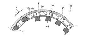
- FIG. 1 is a schematic cross-sectional view of the magnetic gear 9 according to the embodiment of the present invention along the radial direction c.
- FIG. 2 is a partially enlarged view of a cross section of the magnetic gear 9 shown in FIG.
- FIG. 3 is a schematic cross-sectional view of the magnetic gear 9 according to the embodiment of the present invention along the axial direction b.
- the magnetic gear 9 is a device having a mechanism for transmitting torque in a non-contact manner by utilizing the attractive force and the repulsive force of the magnet.
- the magnetic gears 9 shown in FIGS. 1 to 3 are magnetic flux modulation type (harmonic type), and as shown in the figure, the outer diameter side magnet field magnet 5 having a cylindrical (annular; the same applies hereinafter) shape as a whole. (Outer rotor), inner diameter side magnet field magnet 7 (inner rotor) having a cylindrical or columnar shape as a whole, and magnetic flux piece device 1 (center rotor) having a cylindrical shape as a whole are coaxially arranged.
- the outer diameter side magnet field 5 is arranged on the outer side (outer diameter side) in the radial direction with respect to the inner diameter side magnet field 7.
- the magnetic pole piece device 1 is arranged between the outer diameter side magnet field 5 and the inner diameter side magnet field 7.
- the outer diameter side magnet field 5, the inner diameter side magnet field 7, and the magnetic pole piece device 1 are arranged concentrically.
- the outer diameter side magnet field 5 and the inner diameter side magnet field 7 are circumferential in a cross section (hereinafter, radial cross section) cut along the radial direction c of the magnetic gear 9. It has magnetic pole pairs (51, 71) such as a permanent magnet composed of a plurality of N poles and S poles arranged at equal intervals on the top.
- the outer diameter side magnet field 5 has a plurality of magnetic pole pairs 51 and a support member 52 that supports the plurality of magnetic pole pairs 51. Then, on the cylindrical inner peripheral surface of the outer diameter side magnet field 5, a plurality of magnetic pole pairs 51 are oriented in the radial direction c, and the north and south poles are alternately alternated along the circumferential direction.
- the inner diameter side magnet field 7 has a plurality of inner diameter magnetic pole pairs 71 and a columnar inner diameter support member 72 that supports the plurality of inner diameter magnetic pole pairs 71. Then, on the cylindrical outer peripheral surface of the inner diameter side magnet field 7, a plurality of inner diameter magnetic pole pairs 71 are installed along the circumferential direction a along the entire circumference thereof in the same manner as described above.
- the magnetic pole piece device 1 has a plurality of magnetic pole pieces 41 (pole pieces) arranged at intervals (equal intervals) from each other over the entire circumference in the circumferential direction a. Then, for example, when the inner diameter side magnet field 7 is rotated, the magnetic flux of the inner diameter side magnet field 7 is modulated by the magnetic pole piece 41 of the magnetic pole piece device 1, and the modulated magnetic field and the action of the outer diameter side magnet field 5 act. A rotational torque is generated in the magnetic flux piece device 1.
- the magnetic gear 9 constitutes a magnetic geared motor by being integrated with the motor. More specifically, in this magnetic geared motor, the outer diameter side magnet field 5 is a stator (fixer) in which a plurality of coils 6 (see FIG. 2) are installed, and the inner diameter side magnet is generated by the electromotive force of the coils 6.
- the reduction ratio is determined by the ratio of the number of pole pairs of the magnetic pole pairs 51 of the outer diameter side magnet field 5 to the number of pole pairs of the inner diameter magnetic pole pairs 71 of the inner diameter side magnet field 7. According to this, the magnetic pole piece device 1 (low speed rotor) rotates.
- the magnetic geared motor is supplied with a cooling medium D such as air or water in order to protect the above components from heat generated during operation.
- a cooling medium D such as air or water
- FIG. 3 cylindrical gaps between the inner diameter side magnet field 7 and the magnetic pole piece device 1 and between the outer diameter side magnet field 5 and the magnetic pole piece device 1, respectively. G is formed, and the cooling medium D is supplied to each of these cylindrical gaps G so as to flow from one end side to the other end side.
- the cooling medium D is similarly supplied to the gap formed between the outer diameter side magnet field 5 and the housing H located on the outer peripheral side thereof.
- a gas such as air may be supplied to the gap between the outer diameter side magnet field 5 and the housing H.
- a water cooling pipe is installed and cooling water or the like is circulated through the water cooling pipe. You may let me.
- the above-mentioned magnetic pole piece device 1 acts between the above-mentioned two magnet fields (5, 7) adjacent to each other on the inner peripheral side and the outer peripheral side. Since it receives a load that acts along the radial direction, such as an electromagnetic force or a centrifugal load, if sufficient rigidity is not sufficient, deformation occurs in the radial direction c, and the magnetic pole pairs of the above-mentioned magnet field magnets adjacent to each other in the radial direction c. There is a risk of interfering with (51, 71). Therefore, the above-mentioned magnetic pole piece device 1 was configured as follows.
- the magnetic gear 9 can also operate as a magnetic geared generator.
- the magnetic pole piece device 1 center rotor rotates as the inner diameter side magnet field 7 (inner rotor) rotates.
- the operation differs depending on whether the magnetic pole piece device 1 is a magnetic geared motor or a magnetic geared generator, but the structure of the device is the same.
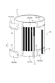
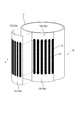
- FIG. 4A is a schematic cross-sectional view of the magnetic pole piece device 1 according to the embodiment of the present disclosure along the radial direction c.
- FIG. 4B is a diagram showing the thermal conductivity and tensile elastic modulus of PAN-based CFRP and pitch-based CFRP in comparison with metals (copper, aluminum, iron).
- FIG. 5 is a schematic cross-sectional view taken along the axial direction b of the LL line of FIG. 4A.
- the magnetic pole piece device 1 is a device (member) that constitutes a magnetic gear 9, such as a magnetic flux modulation type magnetic gear that constitutes a magnetic geared motor, and is a magnet field 7 (inner diameter side magnet field 7) in the magnetic gear 9. It is a device (member) arranged between the outer diameter side magnet field magnet 5 (stator in the case of a magnet geared motor) and the high-speed rotor in the case of a magnetic geared motor.
- the magnetic pole piece device 1 includes an outer peripheral cover member 2 arranged to face the inner peripheral surface of the outer diameter side magnet field 5 and an inner peripheral cover member arranged to face the outer peripheral surface of the inner diameter side magnet field 7. 3 and.
- the outer peripheral cover member 2 and the inner peripheral cover member 3 are members having a cylindrical shape as a whole. Further, the inner peripheral cover member 3 has a diameter smaller than that of the outer peripheral cover member 2, and is coaxially arranged inside the outer peripheral cover member 2.
- a cylindrical space 8 is formed over the entire circumference between the inner peripheral surface of the outer peripheral cover member 2 and the outer peripheral surface of the inner peripheral cover member 3 (in other words, the outer peripheral cover member 2 and the inner peripheral cover member 3 are formed. (Provided so as to sandwich the cylindrical space 8).
- a plurality of magnetic pole piece holders 10 are provided in the cylindrical space 8 by being partitioned by wall members 20 extending along the radial direction c.
- the plurality of magnetic pole piece holders 10 are arranged at predetermined intervals (for example, at equal intervals) along the circumferential direction.
- a long magnetic pole piece 41 (pole piece) is inserted into each of the magnetic pole piece holders 10 so that the longitudinal direction thereof is along the axial direction b.
- the wall member 20 constituting the magnetic pole piece holder 10 is integrally formed together with the outer peripheral cover member 2 and the inner peripheral cover member 3.
- the rigidity of the magnetic pole piece device 1 can be effectively improved.
- the magnetic gear 9 transmits power
- it is generated in the magnetic pole piece device 1 by a load along the radial direction such as an electromagnetic force or a centrifugal force received from the outer diameter side magnet field 5 or the inner diameter side magnet field 7.
- the rigidity against flexural deformation and torsional deformation can be effectively improved.
- the magnetic gear 9 transmits power
- the magnetic pole piece device 1 is deformed and comes into contact with the outer diameter side magnet field 5 and the inner diameter side magnet field 7 arranged through the gap G. You can effectively avoid the risk of losing.
- outer peripheral cover member 2, the inner peripheral cover member 3, and the wall member 20 that are integrally formed are integrally molded of, for example, carbon fiber reinforced plastic (CFRP: Carbon Fiber Reinforced Plastic).
- CFRP Carbon Fiber Reinforced Plastic
- the carbon fiber reinforced plastic is a lightweight material having excellent strength and reliability, and by using this, it is possible to secure excellent rigidity while suppressing an increase in the weight of the magnetic pole piece device 1.
- the pitch CFRP and the PAN CFRP may be combined depending on the application.
- the wall member 20 may include a pitch-based CFRP. Since the pitch-based CFRP is superior in thermal conductivity to the PAN-based CFRP, the wall member 20 adjacent to the magnetic pole piece 41 that generates heat during operation is composed of the pitch-based CFRP, and the fiber orientation thereof is oriented in the radial direction. By doing so, the heat dissipation function of the magnetic pole piece 41 can be effectively improved.
- the heat generated from the magnetic pole piece 41 is transferred to the inner and outer peripheral cover members (2, 3) via the wall member 20.
- heat can be efficiently dissipated and cooled from the air gap G provided on the inner and outer circumferences of the magnetic pole piece device 1.
- the fiber orientation of the outer peripheral cover member 2 and the inner peripheral cover member 3 may be a combination of fiber orientations intersecting the circumferential direction such as ⁇ 45 ° with respect to the circumferential direction and the axial direction.
- the torsional rigidity of the magnetic pole piece device 1 can be efficiently improved.
- the pitch-based CFRP has higher elasticity than the PAN-based CFRP, the deflection and torsional deformation of the magnetic pole piece device 1 situation due to the centrifugal load acting on the magnetic pole piece 41 and the torque load acting on the magnetic pole piece device 1 are efficiently performed. Can be suppressed.
- the CFRP carbon fibers used for the outer peripheral cover member 2, the inner peripheral cover member 3, and the wall member 20 are preferably fibers having an elastic modulus of 400 GPa, preferably 700 GPa or more.
- the higher the elastic modulus of carbon fiber the better the thermal conductivity.
- the thermal conductivity is twice that of iron
- the thermal conductivity is four times that of iron, which is equivalent to that of aluminum. Therefore, by using the carbon fiber having the elastic modulus, it is possible to achieve both the cooling property and the high rigidity of the magnetic pole piece device 1 at a higher level.
- the PAN-based CFRP has higher strength than the pitch-based CFRP. Therefore, PAN-based CFRP may be used for each member of the magnetic pole piece device 1 according to the strength required for the magnetic pole piece device 1.
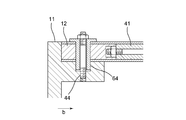
- a rotor end plate 11 for outputting the power transmitted to the magnetic pole piece device 1 is fixed to the end portion of the magnetic pole piece device 1 in the axial direction b.
- a solid member 12 is provided near the end of the cylindrical space 8 in the axial direction b.
- the solid member 12 is made of an insulating material such as the above-mentioned carbon fiber reinforced plastic or glass fiber reinforced plastic (GFRP: Grass Fiber Reinforced Plastic), and is formed of an inner peripheral surface of the outer peripheral cover member 2 and an inner peripheral cover member 3.
- the solid member 12 is the inner peripheral surface of the outer peripheral cover member 2 and the outer peripheral surface of the inner peripheral cover member 3. , And are configured to come into contact with the end faces of the rotor end plates 11).
- the connecting member 13 is embedded in the solid member 12.
- the connecting member 13 is, for example, a T-shaped bolt that has three ends threaded and is fastened to the outer peripheral cover member 2, the inner peripheral cover member 3, and the rotor end plate 11 to connect the three to each other. be.
- the magnetic pole piece 41 held by the magnetic pole piece holder 10 is firmly fixed, and good rigidity can be obtained with a stable structure.
- the plurality of magnetic pole piece holders 10 are arranged at predetermined intervals from each other along the circumferential direction a in the cylindrical space 8.
- An adjacent space 14 defined by a pair of wall members 20 is provided between adjacent magnetic pole piece holders 10 in the cylindrical space 8.
- the adjacent space 14 is filled by arranging the core material 15.
- the core material 15 is, for example, a polymer hard foam such as urethane, polyetherimide, polyimide, polymethacrylimide, or a polymer material alone or a composite of a polymer material and pulp fiber, aramid fiber, glass fiber, carbon fiber, or the like. It is composed of a lightweight non-magnetic material such as a honeycomb structure made of a material.
- the rigidity of the magnetic pole piece device 1 can be reduced even when the outer peripheral cover member 2 and the inner peripheral cover member 3 constituting the magnetic pole piece device 1 are thinned. It can be enhanced more effectively.
- FIG. 6 is a schematic cross-sectional view showing the vicinity of the outer peripheral cover member 2 and the inner peripheral cover member 3 of FIG. 5 in an enlarged manner.
- the outer peripheral cover member 2 includes a first layer 2a having a fiber direction in the first direction and a second layer 2b having a fiber direction in the second direction.
- the inner peripheral cover member 3 includes a first layer 3a having a fiber direction of the first direction and a second layer 3b having a fiber direction of the second direction.
- the first direction is a direction parallel to the circumferential direction a
- the second direction is a direction intersecting the circumferential direction a in the plane composed of the circumferential direction a and the axial direction b, for example, with respect to the axial direction b.
- the direction is ⁇ 45 degrees.
- the wall member 20 is a carbon fiber reinforced plastic whose fiber direction is a third direction or a fourth direction.
- the third direction is a direction parallel to the radial direction c
- the fourth direction is an axial direction b and a radial direction. It is a direction that intersects in the radial direction in the plane composed of c, for example, a direction that forms ⁇ 45 degrees with respect to the axial direction b.
- the outer peripheral cover member 2 and the inner peripheral cover member 3 having a hybrid structure in which a plurality of different layers are combined in this way, when the magnetic gear 9 transmits power, the outer diameter side magnet field 5 or the inner diameter side It is possible to effectively improve the rigidity against flexural deformation caused by the magnetic pole piece device 1 due to the load received from the magnet field 7 and the rigidity against torsional deformation due to torque transmission.
- centrifugal force acts on the magnetic pole piece device 1 along the radial direction c due to rotation, by arranging the first layer (2a, 3b) having the fiber direction in the first direction along the circumferential direction a.
- Centrifugal force in the radial direction c can be received as a hoop load by continuous carbon fibers having high rigidity and high strength, and bending deformation of the magnetic pole piece device 1 due to centrifugal force can be effectively suppressed.
- the magnetic pole piece device 1 needs to transmit the torque load from one end plate toward the other end plate, the second layer (2b) having the fiber direction in the second direction intersecting the circumferential direction a. By arranging 3b), the rigidity against twisting can be effectively improved.
- the first layer 2a of the outer peripheral cover member 2 is arranged on the inner peripheral side of the second layer 2b, but the first layer 2a is arranged on the outer peripheral side of the second layer 2b. May be good.
- the first layer 3a of the inner peripheral cover member 3 is arranged on the outer peripheral side of the second layer 3b, the first layer 3a may be arranged on the inner peripheral side of the second layer 3b.
- both the outer peripheral cover member 2 and the inner peripheral cover member 3 are composed of a plurality of layers (2a, 2b, 3a, 3b), but the outer peripheral cover member 2 or the inner peripheral circumference is shown. Only one of the cover members 3 may be composed of a plurality of layers.
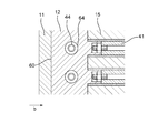
- FIG. 7 is a first modification of FIG. 5, and FIG. 8 is an enlarged view of the range M of FIG.
- the magnetic pole piece 41 held by the magnetic pole piece holder 10 includes a plurality of magnetic pole plate members 41a laminated along the axial direction b, as shown in FIG.
- Each of the plurality of magnetic pole plate members 41a has a hole portion 43 provided at a position corresponding to each other, and a fastening rod 44 extending along the axial direction b is inserted into the hole portion 43.
- the end portion of the fastening rod 44 is fastened to the above-mentioned solid member 12.
- the plurality of magnetic pole plate members 41a constituting the magnetic pole piece 41 are fixed to the rotor end plate 11 by the fastening rod 44 together with the outer peripheral cover member 2 and the inner peripheral cover member 3 via the solid member 12.
- the torsional rigidity of the magnetic pole piece device 1 is more effectively improved, the shear stress acting on the fastening bolt 13 and the bolt 14 is effectively reduced, and a larger torque can be transmitted. It will be possible.
- FIG. 9 is a second modification of FIG.
- FIG. 10 is a schematic view of a cross section taken along the axial direction b of the NN line of FIG.
- the above-mentioned adjacent space 14 defined by the pair of wall members 20 is configured as a hollow space (hollow core) between the adjacent magnetic pole piece holders 10 in the cylindrical space 8.
- the space 14 between adjacent spaces is not filled with the core material 15 as shown in FIG. 5).
- the outer peripheral cover member 2 and the inner peripheral cover member 3 that surround the adjacent space 14 are provided with cooling holes 17 that communicate with the outside.
- cooling holes 17 are provided in both the outer peripheral cover member 2 and the inner peripheral cover member 3.
- the cooling medium D (see FIG. 3) flowing through the gap G receives centrifugal force and is taken into the adjacent space 14 which is a hollow core from the cooling hole 17 provided in the inner peripheral cover member 3 inside.
- the cooling hole 17 may be provided in either the outer peripheral cover member 2 or the inner peripheral cover member 3.
- FIG. 11 is a flowchart schematically showing a manufacturing method of the magnetic pole piece device 1 according to the embodiment of the present disclosure.
- one of the outer peripheral cover member 2 or the inner peripheral cover member 3 constituting the magnetic pole piece device 1 and the wall member 20 are integrally formed to integrally form the first intermediate molded products 54, 54'(described later). (See FIG. 13 or FIG. 15) is manufactured (step S1).
- the magnetic pole piece device 1 is completed by attaching the other of the outer peripheral cover member 2 or the inner peripheral cover member 3 to the second intermediate molded products 55 and 55'and integrally molding the two (step S3).
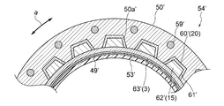
- FIG. 12 is a flowchart showing an embodiment of the manufacturing method of FIG. 13A to 13C are schematic views schematically showing the manufacturing process of the magnetic pole piece device 1 in each process of FIG. 12.
- a molding die 50 corresponding to the first intermediate molded product 54 is prepared (step S100). That is, as shown in FIG. 13A, the surface shape of the molding die 50 on the outer side in the radial direction is configured to match the surface shape on the inner side in the radial direction of the first intermediate molded product 54. Specifically, on the radial outer surface of the molding die 50, a plurality of convex portions 50a are formed along the circumferential direction a so as to correspond to the radial inner surface shape of the first intermediate molded product 54 described later. It is provided.
- the molding die 50 has a built-in heater 59 that can be operated when heat treatment is performed later.
- the heater 59 includes, for example, a plurality of heating wires provided along the radial direction a.
- step S101 the constituent material of the first intermediate molded product 54 is laid on the molding mold 50 prepared in step S100 (step S101).
- the constituent material laid in step S101 is, for example, a prepreg material obtained by impregnating a fiber base material with the above-mentioned carbon fiber reinforced plastic or the like with a thermosetting resin.
- the first constituent material 60 corresponding to the wall member 20 is laid along the radial outer surface of the molding die 50.
- the non-magnetic material 62 corresponding to the core material 15 is inserted into the recess 61 on the radial outer surface of the first constituent material 60 (as shown in FIG. 9, the adjacent space 14 is filled with the core material 15).
- the second constituent material 63 corresponding to the outer peripheral cover member 2 is laid from the outside in the radial direction with respect to the first constituent material 60 into which the non-magnetic material 62 is inserted.
- step S102 the radial outer peripheral side of the constituent material laid on the molding die 50 is covered with the vacuum back 49 (step S102), and the rubber heater 53 is further installed on the radial outer peripheral side of the vacuum back 49 (step S103).
- step S104 the constituent materials laid on the molding die 50 are heated and cured.
- step S105 the first intermediate molded product 54 in which the outer peripheral cover member 2 and the magnetic pole piece holder 10 are integrally formed (cocure integrally molded) is completed (step S105).
- the magnetic pole piece 41 is inserted into the recess corresponding to the magnetic pole piece holder 10 in the first intermediate molded product 54 taken out from the molding die 50 (step S106), and the second intermediate molded product is formed. 55 is manufactured (step S107).
- the magnetic pole piece 41 inserted in step S106 is integrally molded together with the outer peripheral cover member 2 and the wall member 20 in steps S101 to S105.
- the constituent material 64 corresponding to the inner peripheral cover member 3 is laid on the surface of the second intermediate molded product 55 on the radial inner peripheral side (step S108).
- the constituent material 64 laid in step S108 is the same as the constituent material laid in step S101.
- a prepreg material obtained by impregnating a fiber base material with the above-mentioned carbon fiber reinforced plastic or the like with a thermosetting resin is used. ..
- the inner peripheral side in the radial direction of the constituent material laid in step S108 is covered with the vacuum back 56 (step S109), and the rubber heater 57 is further installed on the inner peripheral side of the vacuum back 56 (step S110).
- the rubber heater 57 arranged in step S110 is operated to heat the rubber heater 57 to perform the curing process (step S111).
- the inner peripheral cover member 3 is integrally molded with the second intermediate molded product 55 to complete the magnetic pole piece device 1.
- the inner peripheral cover member 3 is further integrally molded by using the second intermediate molded product 55 in which the magnetic pole piece 41 is inserted into the first intermediate molded product 54 as a substantially new molding mold. In addition to improving the shape accuracy of the product, extra processing and bonding processes are not required, which can improve productivity and reduce costs.
- step S108 cobond molding may be performed by interposing an adhesive between the second intermediate molded product 55 and laying the constituent material 64 corresponding to the inner peripheral cover member 3.
- FIG. 14 is a flowchart showing another embodiment of the manufacturing method of FIG. 15A to 15C are schematic views schematically showing the manufacturing process of the magnetic pole piece device 1 in each process of FIG. 14.
- a molding die 50'corresponding to the first intermediate molded product 54' is prepared (step S200). That is, as shown in FIG. 15A, the surface shape on the inner side in the radial direction of the molding die 50'is configured to match the surface shape on the outer side in the radial direction of the first intermediate molded product 54'. Specifically, on the radial inner surface of the molding die 50 ′, a plurality of convex portions 50a ′ are formed in the circumferential direction a so as to correspond to the radial outer surface shape of the first intermediate molded product 54 ′ described later. It is provided along.
- the molding die 50 ′ has a built-in heater 59 ′ that can be operated when heat treatment is performed later.
- the heater 59' includes, for example, a plurality of heating wires provided along the radial direction a.
- the constituent material of the first intermediate molded product 54' is laid on the molding mold 50'prepared in step S200 (step S201).
- the constituent material laid in step S201 is, for example, a prepreg material obtained by impregnating a fiber base material with the above-mentioned carbon fiber reinforced plastic or the like with a thermosetting resin.
- the first constituent material 60'corresponding to the wall member 20 is laid along the radial inner surface of the molding die 50'.
- the non-magnetic material 62'corresponding to the core material 15 is inserted into the recess 61'on the radial outer surface of the first constituent material 60'(as shown in FIG. 9, the core material is inserted into the adjacent space 14).
- the second constituent material 63'corresponding to the outer peripheral cover member 2 is laid from the inside in the radial direction with respect to the first constituent material 60'in which the non-magnetic material 62'is inserted.
- step S202 the inside of the constituent material laid on the molding die 50'in the radial direction is covered with a vacuum back 49'(step S202), and a rubber heater 53'is further installed inside the vacuum back 49'in the radial direction (step S203). ..
- a rubber heater 53' is further installed inside the vacuum back 49'in the radial direction.
- the magnetic pole piece 41 is inserted into the recess corresponding to the magnetic pole piece holder 10 in the first intermediate molded product 54'taken out from the molding die 50' (step S206), and the second intermediate is inserted.
- a molded product 55' is manufactured (step S207).
- the magnetic pole piece 41 inserted in step S206 is together with the inner peripheral cover member 3 and the wall member 20 in steps S201 to S205. It may be integrally molded. That is, in the second intermediate molded product 55, when the first intermediate molded product 54 is integrally molded, the inner peripheral cover member 3 is inserted into the wall member 20 constituting the magnetic pole piece holder 10 and the magnetic pole piece holder 10. Manufactured by integrally molding with 41. In this case, the magnetic pole piece device 1 can be manufactured more easily by integrally molding the magnetic pole piece 41 in addition to the inner peripheral cover member 3 and the wall member 20.
- the constituent material 64'corresponding to the outer peripheral cover member 2 is laid on the radial outer surface of the second intermediate molded product 55' (step S208).
- the constituent material 64 ′ laid in step S208 is the same as the constituent material laid in step S201, and for example, a prepreg material obtained by impregnating a fiber base material with a thermosetting resin with the above-mentioned carbon fiber reinforced plastic or the like is used. Be done.
- the radially outer side of the constituent material laid in step S208 is covered with a vacuum back 56'(step S209), and a rubber heater 57'is further installed on the outer peripheral side of the vacuum back 56' (step S210).
- step S210 the rubber heater 57'arranged in step S210 is operated to heat the rubber heater 57', thereby performing the curing process (step S211).
- step S211 the outer peripheral cover member 2 is integrally molded with the second intermediate molded product 55', and the magnetic pole piece device 1 is completed.
- the outer peripheral cover member 2 is formed. In addition to improving the shape accuracy of the product, extra processing and bonding processes are not required, which can improve productivity and reduce costs.
- step S208 cobond molding may be performed by interposing an adhesive between the second intermediate molded product 55'and laying the constituent material 64' corresponding to the outer peripheral cover member 2.
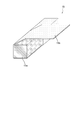
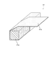
- 16A to 16C are perspective views showing a configuration example of the core material 15.
- the core material 15 includes a core body 15a and a first cover member 15b that at least partially surrounds the core body 15a.
- the first cover member 15b is provided so as to at least partially surround the core body 15a extending along the axial direction.
- the first cover member 15b is a single long member, and is wound around the core main body 15a over the entire circumference.
- the core body 15a is configured as a solid foam core.
- the foam core is a lightweight non-magnetic material as described above, for example, a polymer hard foam such as urethane, polyetherimide, polyimide, polymethacrylicimide, or a polymer material alone or a polymer material and pulp fiber, aramid fiber.
- a honeycomb structure or the like made of a composite material with glass fiber, carbon fiber or the like.
- the first cover member 15b is a fiber reinforced resin, for example, carbon fiber reinforced plastic (CFRP: Carbon Fiber Reinforced Plastic), glass fiber reinforced plastic (GFRP: Glass Fiber Reinforced Plastic), aramid fiber reinforced plastic (AFRP: Aramid Fiber Reinforce). , Basalt Fiber Reinforced Plastics (BFRP: Basalt Fiber Reinforced Plastics), Boron Fiber Reinforced Plastics (BFRP: Boron Fiber Reinforced Plastics), Keflar Fiber Reinforced Plastics (KFRP: Kevaler Fiber Reinforced Plastics) It is composed of Plastics) and the like.
- CFRP Carbon Fiber Reinforced Plastic
- GFRP Glass Fiber Reinforced Plastic
- AFRP Aramid Fiber Reinforce
- Basalt Fiber Reinforced Plastics Basalt Fiber Reinforced Plastics
- BFRP Basalt Fiber Reinforced Plastics
- Boron Fiber Reinforced Plastics BFRP: Boron Fiber Reinforced Plastics
- Keflar Fiber Reinforced Plastics Kevaler Fiber Reinforced Plastics
- the first cover member 15b is made of fiber reinforced plastic, a prepreg material in which a fiber base material is impregnated with a thermosetting resin is arranged around the core member 15a.
- the first cover member 15b is attached to the outer peripheral cover member 2 and the inner peripheral cover member 3 and is cured at the same time as the outer peripheral cover member 2 and the inner peripheral cover member 3, so that the first cover member 15b is attached to the outer peripheral cover member 2 and the inner peripheral cover member 2.
- It can be integrally configured with the peripheral cover member 3. As a result, good structural strength can be obtained, and in particular, weight reduction and workability during manufacturing can be expected while maintaining axial rigidity and torsional rigidity with respect to torque transmission.
- the first cover member 15b is divided with respect to each surface of the core main body 15a having a substantially quadrangular cross-sectional shape in a cross section perpendicular to the axial direction, and each surface.
- the first cover member 15b may be formed by being attached to the first cover member 15b.
- two cover members 15b1 and 15b2 having a substantially U-shape cover the core body 15a from both sides in a cross section perpendicular to the axial direction. It may be configured to be spliced as follows. In this case, as shown in FIG.
- the core body 15a is configured as a solid member made of fiber reinforced plastic.
- Fiber-reinforced plastics include, for example, Pitch-based and PAN-based carbon fibers, glass fibers, polymer fibers, etc., and resins such as epoxy, polyester, phenol, bismaleimide, polyurethane, and other thermocurable resins, thermoplastic resin polyimide, and PP.
- Polypropylene, Polyvinyl Chloride, Polyester, Polyetherimide, Nylon and other thermoplastic resins can be used.
- the first cover member 15b may be configured as, for example, a resin sheet containing a film adhesive.
- the core body 15a made of fiber reinforced plastic is formed by machining, for example, from a laminated plate.
- the outer cover member 2 and the inner cover member 3 are machined.
- the shape of the processed core body 15a can be suitably adapted to realize an integrated structure having good rigidity.
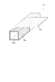
- the core body 15a is made of fiber reinforced plastic as in the embodiment shown in FIG. 16B, but has a hollow structure provided with a hollow portion 15a1 that opens in the axial direction. Have.
- the core body 15a having a hollow structure in this way, the weight of the magnetic pole piece device can be reduced. Further, by introducing a cooling medium into the hollow portion 15a1, it is possible to improve the cooling performance of the magnetic pole piece device 1.
- Such a hollow portion 15a1 can be easily formed by, for example, arranging a fiber reinforced resin prepreg around a core material having a shape corresponding to the hollow portion 15a1, performing a curing treatment, and then removing the core material. Is.
- the present embodiment illustrates the case where the cross-sectional shape of the hollow portion 15a1 is substantially rectangular, the cross-sectional shape of the hollow portion 15a may be any shape such as a circle or a polygon. Further, in the present embodiment, the case where the core main body 15a has one hollow portion 15a1 is illustrated, but a plurality of hollow portions 15a1 may be provided.
- FIG. 18 is a perspective view showing a configuration example of the magnetic pole piece 41 held by the magnetic pole piece holder 10.
- the magnetic pole piece 41 includes a magnetic pole piece main body 41a and a second cover member 41b that at least partially surrounds the magnetic pole piece main body 41a.
- the second cover member 41b may be provided so as to partially surround the magnetic pole piece main body 41a on a cross section orthogonal to the axial direction, or may be provided so as to surround the entire circumference of the magnetic pole piece main body 41a. May be good.
- the second cover member 41b is, for example, a film adhesive such as an epoxy resin or a fiber reinforced resin prepreg such as KFRP, and may be a combination thereof. As a result, the second cover member 41b is interposed between the h magnetic pole piece main body 41 and the outer cover member 2 or the inner cover member 3, so that the shear strength between the two can be effectively improved.
- the second cover member 41b may be configured as an elastic member such as a silicon sheet or a rubber sheet.
- the damping effect of the second cover member 41b can effectively attenuate the vibration generated in the magnetic pole piece device 1.
- the same effect can be expected when a Kevlar fiber reinforced prepreg having vibration damping characteristics is used as the second cover member 41b.
- the second cover member 41b may be configured as a foam sheet.
- the foam sheet has flexibility and the thickness can be adjusted, a gap generated between the two due to the dimensional tolerance when the magnetic pole piece 41 is assembled to the outer cover member 2 or the inner cover member 3.
- the magnetic pole piece device 1 can be easily assembled because it can be absorbed even when the magnet is filled or interference occurs. Further, even if a thermal expansion difference occurs between the magnetic pole piece 41 and the peripheral configuration even when heated during manufacturing or operation, it can be mitigated by the second cover member 41b, so that the interface peeling and the like can be effectively prevented. It can be avoided.
- FIG. 18 shows a case where a single second cover member 41b is wound around the magnetic pole piece main body 41a.
- the prepreg to be the second cover member 41b is wound around the magnetic pole piece main body 41a, then assembled to the outer cover member 2 and the inner cover member 3, and these are integrally cured to harden the second cover member 41b to the outside.
- the cover member 2 and the inner cover member 3 can be integrally formed with a good adhesive force, and the rigidity can be improved and the manufacturing process can be simplified.
- the second cover member 41b is attached by being cut so as to correspond to each surface of the magnetic pole piece main body 41a having a substantially quadrangular shape in a cross section perpendicular to the axial direction, following the above-mentioned first cover member 15b. It may be configured by being pasted in a substantially U shape (covering the remaining surfaces except one surface) and spliced.
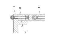
- FIG. 19 is a schematic view showing a configuration at a connection portion between the solid member 12 and the magnetic pole piece holder 10 in the magnetic pole piece device 1.
- the solid member 12 is interposed between the end portion of the magnetic pole piece holder 10 in the axial direction b and the rotor end plate 11, so that the end portion of the magnetic pole piece holder 10 and the rotor end plate 11 are held together. It is a member for connecting.
- the solid member 12 has a substantially cylindrical shape, and the end portion 12a on the magnetic pole piece holder 10 side along the axial direction b is provided with a concave-convex shape 19 in which irregularities are alternately arranged along the circumferential direction. ..
- the concave-convex shape 19 has a shape complementary to the end of the magnetic pole piece holder 10 to be connected to the solid member 12. Specifically, the concave portion 19a1 of the concave-convex shape 19 corresponds to the core material 15 having a convex shape at the end of the magnetic pole piece holder 10, and the convex portion 19a2 has a magnetic pole piece 41 having a concave shape at the end of the magnetic pole piece holder 10. Corresponds to.
- Such a concave-convex shape 19 can facilitate the positioning performed when the solid member 12 is attached to the magnetic pole piece holder 10. This makes it possible to omit the jigs conventionally used for such positioning work.
- the concave-convex shape 19 can be formed by post-processing on the end portion 12a of the bulk-molded solid member 12.
- the uneven shape 19 can be formed with high accuracy by performing machining as post-processing. Since the solid member 12 has a substantially cylindrical shape, for example, when molding is performed, spring-in occurs during heat molding, which makes it difficult to maintain the accuracy of the radius of curvature. By doing so, good shape accuracy can be obtained.
- the solid member 12 having such an uneven shape 19 may be produced by using a 3D printer. In this case, since it is not necessary to perform curing molding or machining, high curvature accuracy can be obtained.
- the solid member 12 having such a configuration is attached to the outer cover member 2 or the inner cover member 3 by using, for example, an adhesive.
- 20A and 20B are schematic views showing an example of mounting the solid member 12 shown in FIG. 19 to the outer cover member 2 or the inner cover member 3.
- the solid member 12 is divided into a plurality of sub-members 12a, 12b, 12c, ... Along the circumferential direction, each of which is the outer cover member 2 or the inner cover member, respectively. It is attached to 3 using, for example, an adhesive.
- FIGS. 20A and 20B after the solid member 12 is attached to the inner cover member 3, the magnetic pole piece 41 and the core material 15 are attached to the solid member 12 fixed to the inner cover member 3. The situation is shown.
- the positioning accuracy of the magnetic pole piece 41 and the core material 15 to be attached later can be improved. This is advantageous in that good workability can be obtained even when the magnetic pole piece device 1 is large.
- the solid member 12 when the solid member 12 is attached to the inner cover member 3, a handling facility such as a crane is required when the magnetic pole piece device 1 is large, but if the solid member 12 is attached first by the handling facility, Since the remaining magnetic pole pieces 41 and the core material 15 are relatively lightweight, handling equipment is not required, and the work can be simplified.
- a handling facility such as a crane is required when the magnetic pole piece device 1 is large, but if the solid member 12 is attached first by the handling facility, Since the remaining magnetic pole pieces 41 and the core material 15 are relatively lightweight, handling equipment is not required, and the work can be simplified.
- FIG. 21 is a schematic view showing another mounting example of the solid member 12.
- the solid member 12, the magnetic pole piece 41, and the core material 15 are integrally attached to the inner cover member 3 with the magnetic pole piece 41 and the core material 15 attached in advance to the solid member 12. Can be attached to.
- the work can also be simplified by performing the mounting in this way.
- the fiber direction is set so that the coefficient of thermal expansion of these members is close to that of the magnetic pole piece 41. ..
- the fiber direction is set so that the coefficient of thermal expansion of these members is close to that of the magnetic pole piece 41. ..
- the fiber directions in the outer cover member 2, the inner cover member 3, and the wall member 20 may be set avoiding the axial direction b. Specifically, by setting the fiber direction to 90 ° with respect to the axial direction b, it is possible to effectively receive the centrifugal load and the electromagnetic force acting on the magnetic pole piece 41. Further, by setting the fiber direction to 45 ° with respect to the axial direction b, the torque load of the rotor can be received.
- FIG. 22A is an example of a vertical cross-sectional view of a connecting structure including the solid member 12 and the rotor end plate 11 along the axial direction b
- FIG. 22B is a plan view showing the connecting structure of FIG. 22A from the outside in the radial direction.
- the solid member 12 has a metal pad 62 provided on the end face 60 facing the rotor end plate 11 to be connected.
- a plurality of metal pads 62 are provided on the end surface 60 along the circumferential direction. These metal pads 62 are provided at positions that do not interfere with the fastening rod 44 described above.
- the distance between adjacent metal pads 62 is set to, for example, equal intervals.
- Each of the metal pads 62 has a substantially hemispherical shape and is formed from, for example, a metal material.
- FIG. 23A is another example of a vertical cross-sectional view of the connecting structure including the solid member 12 and the rotor end plate 11 along the axial direction b
- FIG. 23B is a plan view showing the connecting structure of FIG. 23A from the outside in the radial direction. be.
- the solid member 12 and the rotor end plate 11 are provided with a guide bush 64 provided along the connecting bolt 44.
- a guide bush 64 By providing such a guide bush 64, the shearing force generated in the fastening bolt 44 is received by the guide bush 64, and the shear failure of the fastening bolt 44 can be effectively prevented, so that the reliability can be improved.
- the guide bush 64 is provided substantially parallel to the axial direction b. As a result, by inserting the guide bush 64 into the hole 43 into which the fastening rod 44 is inserted, the guide bush 64 can be attached without further machining.
- the guide bush 64 is continuously provided over the solid member 12 and the rotor end plate 11. As a result, for example, when assembling the solid member 12 and the rotor end plate 11, the guide bush 64 is first attached to the solid member 12 side, and then, when the rotor end plate 11 is assembled, the guide bush 64 is used for positioning. Is possible, and the assembly dimensional accuracy can be effectively improved.
- FIG. 24A is another example of a vertical cross-sectional view of the connecting structure including the solid member 12 and the rotor end plate 11 along the axial direction b
- FIG. 24B is a plan view showing the connecting structure of FIG. 24A from the outside in the radial direction. be.
- the solid member 12 and the rotor end plate 11 are connected by providing the fastening bolt 44 perpendicularly to the axial direction b. Also in this case, by providing the guide bush 64 along the fastening bolt 44 according to the above-described embodiment, the guide bush 64 receives the shearing force generated in the fastening bolt 44, so that the shearing failure of the fastening bolt 44 is effective. In addition to being able to avoid this, positioning in the axial direction b is possible, and the assembly dimensional accuracy can be effectively improved.
- FIG. 25 is a perspective view showing another configuration example of the core material 15.
- the core material 15 may have a hollow structure having a hollow portion 15a1 extending along the axial direction b, as in the core main body 15a shown in FIG. 16C. In this case, good structural strength can be obtained while improving the cooling performance by circulating a cooling medium such as cooling air through the hollow portion 15a1.
- FIG. 26 is a schematic view showing the manufacturing process of the core material 15 shown in FIG. 25.
- a core material 70 having a substantially cylindrical shape extending along the axial direction b is prepared so as to correspond to the hollow portion 15a1.
- the prepreg 72 for forming the core material 15 is wound along the outer surface of the core material 70, and the core material 15 is formed by performing a hardening treatment.
- the core material 15 is completed by removing the core material from the molded core material 15 (pulling it out along the axial direction).
- a core material 15 having a hollow structure can be manufactured without machining.
- the cross-sectional shape of the hollow portion 15a1 may be any shape such as a polygon or a star. Further, in the present embodiment, the case where the core material 15 has one hollow portion 15a1 is illustrated, but a plurality of hollow portions 15a1 may be provided.
- the core material 70 may also be hardened together with the core material 15 by using a prepreg material. In this case, the core material 15 and the core material 70 are simultaneously cured, so that the molding process can be simplified.
- FIG. 27 is an example of a cross-sectional view perpendicular to the axial direction b of the core material 15.
- a damping member 74 for damping vibration may be provided on at least a part of the surface of the core material 15 facing the outer cover member 2 and the inner cover member 3 constituting the magnetic pole piece holder 10.
- the first damping member 74A is provided on the first surface 75A of the core material 15 facing the outer cover member 2
- the second damping member 74B is provided on the second surface 75B facing the inner cover member 3. Be done.
- vibration can be absorbed and good seismic performance can be obtained.
- the first damping member 74A is provided along the first surface 74A facing the outer cover member 2 which is easily affected by vibration, it is easy to obtain a damping action.
- FIG. 28 is a modified example of FIG. 27.
- the core material 15 may be divided into a plurality of plate-shaped members 76 along the thickness direction.
- the magnetic pole piece holder 10 By forming the magnetic pole piece holder 10 into a divided structure in this way, friction is generated between the plate-shaped members 76 when vibration is generated, so that vibration energy is converted into thermal energy and a good damping effect can be obtained.
- the third damping member 74C may be provided between the two adjacent plate-shaped members 76. By providing the third damping member 74C inside the core material 15 in this way, the vibration propagating inside can be absorbed while being repeatedly reflected between the damping members, and the damping effect can be expected to be improved.
- each of the above-mentioned damping members 74 is not limited, but for example, a polymer fiber reinforced composite material can be used. Since the polymer fiber reinforced composite material can be simultaneously cured with the outer cover member 2, the inner cover member 3, and the wall member made of fiber reinforced plastic, better structural strength can be obtained by integrally forming with these members. Can be obtained. Further, the damping member 74 may be formed of a resin-based highly elastic material. In this case, the elasticity of the damping member 74 absorbs the vibration, and the damping characteristic can be obtained more effectively.
- a sliding member may be arranged in place of or in addition to the third damping member 74C between the two adjacent plate-shaped members 76.
- a resin material such as Teflon (registered trademark) can be used, and it is possible to effectively prevent the divided members from being worn by friction.
- the natural frequency of the magnetic pole piece holder 10 may be adjusted by appropriately changing the division pattern.
- excellent damping characteristics can be obtained by setting the division pattern so that the natural frequency of the magnetic pole piece holder 10 is different from the vibration frequency generated in the magnetic pole piece holder 10.
- the division pattern is shown as an example in the case where the thickness is uniform in FIG. 28, but the thickness may be adjusted so that the required damping characteristic can be obtained, for example, the outside is fine and the inside is rough. good.
- FIG. 29 is another modification of FIG. 27.
- the core member 15 shown in FIG. 27 is divided into a first member 15-1 on the outer cover member 2 side and a second member 15-2 on the inner cover member 3 side.
- the damping characteristics can be improved by arranging the fourth damping member 74D also at the interface between the first member 15-1 and the second member 15-2.
- Such a core material 15 is formed by laminating the materials of the first member 15-1 and the second member 15-2, respectively, and then when assembling the two members, the first member 15-1 and the second member 15-
- the fourth damping member 74D is laminated and molded at the interface of 2.
- the fourth damping member 74D When an elastic adhesive is used as the fourth damping member 74D, the first member 15-1 and the second member 15-2 are each cured and molded, and then the fourth damping member 74D, which is an elastic adhesive, is formed at the interface between the first member 15-1 and the second member 15-2. May be arranged and both may be adhered to complete the core material 15. This can be expected to improve the internal quality of the magnetic pole piece holder 10.
- FIG. 30 is another modification of FIG. 27.
- a fifth damping member 74E is further provided along the hollow portion 15a1.
- Such a fifth damping member 74E can be arranged by winding the damping material around the outer surface of the core material 70 when the hollow portion 15a1 is formed by using the core material 70 as described above.
- a sixth damping member 74F may be provided on at least one outer surface of the outer cover member 2 or the inner cover member 3.
- FIG. 31A is a modification of FIG.
- the sixth damping member 74F is provided on at least a part of the outer surface (diameter outer surface) of the outer cover member 2 when viewed in a cross section perpendicular to the axial direction b.
- the sixth damping member 74F is widely provided along the outer surface of the outer cover member 2.
- the damping characteristics can be improved by providing the sixth damping member 74F in this way.
- the damping characteristics can be effectively improved by providing the sixth damping member 74F on the outer surface of the outer cover member 2 as in this modification. ..
- FIG. 31B is another modification of FIG. In this modification, in addition to the modification shown in FIG. 31A, the sixth damping member 74F is also provided on at least a part of the outer surface (diametrically inner surface) of the inner cover member 3. In this modification, the sixth damping member 74F is widely provided along the outer surface of the inner cover member 3. By providing the sixth damping member 74F on the outer surfaces of both the outer cover member 2 and the inner cover member 3 in this way, the damping characteristics of the magnetic pole piece device 1 can be further improved.
- Such a sixth damping member 74F may be formed from a material containing a fiber reinforced composite material such as a polymer fiber reinforced composite material. Since such a material can be simultaneously cured with the outer cover member 2 and the inner cover member 3 made of fiber reinforced plastic, the sixth damping member 74F is integrated with the outer cover member 2 and the inner cover member 3. This makes it possible to improve the damping characteristics while maintaining the structural strength.
- the sixth damping member 74F may be provided only on the outer surface of the inner cover member 3.
- FIG. 31C is another modification of FIG.
- the seventh damping member 74G is provided so as to at least partially surround the core material 15 when viewed in a cross section perpendicular to the axial direction b.
- the seventh damping member 74G is provided so as to surround the entire circumference of the core material 15.
- the damping characteristics can be improved by providing the seventh damping member 74G in this way.
- Such a seventh damping member 74G may be formed from a material containing a fiber reinforced composite material such as a polymer fiber reinforced composite material, as in the case of the sixth damping member 74F described above. Since such a material can be simultaneously cured with the outer cover member 2 and the inner cover member 3 made of fiber reinforced plastic, the seventh damping member 74G is integrated with the outer cover member 2 and the inner cover member 3. This makes it possible to improve the damping characteristics while maintaining the structural strength.
- a fiber reinforced composite material such as a polymer fiber reinforced composite material
- FIG. 31D is another modification of FIG.
- the sixth damping member 74F is provided on the outer surfaces of the outer cover member 2 and the inner cover member 3, respectively, and the seventh damping member 74G surrounds the core material 15, which is a combination of the above-mentioned modifications. It is provided as follows. By providing both the sixth damping member 74F and the seventh damping member 74G in this way, the damping characteristics can be further improved.
- the magnetic gear magnetic pole piece device is An outer peripheral cover member (for example, the outer peripheral cover member 2 of the above embodiment) and an inner peripheral cover member (for example, the outer peripheral cover member 2 of the above embodiment) which are coaxially arranged on the outer and inner sides of the magnetic gear (for example, the magnetic gear 9 of the above embodiment) and have a cylindrical shape, respectively.
- a magnetic pole piece holder (for example, the magnetic pole piece holder 10 of the above embodiment) formed by partitioning with a member (for example, the wall member 20 of the above embodiment) and A magnetic pole piece held in the magnetic pole piece holder (for example, the magnetic pole piece 41 of the above embodiment) and With The inner ring member, the outer ring member, and the wall member are integrally formed.
- the outer peripheral cover member and the inner peripheral cover member are connected to each other by a wall member extending in the radial direction, and by integrally forming these, a magnetic pole having excellent rigidity.
- One-sided device can be realized.
- the magnetic pole piece device is deformed, which effectively risks contacting the outer diameter side magnet field and the inner diameter side magnet field arranged through the gap. Can be avoided.
- the outer peripheral cover member and the inner peripheral cover member are connected members (for example, the connecting member 13 of the above embodiment) embedded in a solid member (for example, the solid member 12 of the above embodiment) arranged in the cylindrical space. Is fixed to the rotor end plate (for example, the rotor end plate 11 of the above embodiment) via.
- the outer peripheral cover member, the inner peripheral cover member and the rotor end plate are firmly fixed to each other via the connecting member embedded in the solid member, and a stable structure has good rigidity. can get.
- the solid member has a shape complementary to the end of the rotor end plate.
- the solid member since the solid member has a complementary shape to the end portion of the rotor end plate, the complementary shape is used when connecting the solid member to the rotor end plate. Both can be easily positioned.
- the solid member has at least one metal pad (for example, the metal pad 62 of the above embodiment) provided on the end face facing the rotor end plate.
- the solid member and the rotor end plate are provided with a guide bush (for example, the guide bush 64 of the above embodiment) provided along the connecting bolt.
- the shearing force generated in the fastening bolt is received by the guide bush, and the reliability can be improved by effectively preventing the shearing failure of the fastening bolt. ..
- the magnetic pole piece includes a plurality of magnetic pole plate materials (for example, the magnetic pole plate material 41a of the above embodiment) laminated along the axial direction.
- the plurality of magnetic pole plate materials are fixed to the solid member via a fastening rod (for example, the fastening rod 44 of the above embodiment) through which holes provided in each of the plurality of magnetic pole plates are inserted.
- a magnetic pole piece composed of a plurality of magnetic pole plate materials laminated along the axial direction is connected by a fastening rod together with an outer peripheral cover member and an inner peripheral cover member via a solid member. Can be fixed to the rotor end plate.
- the outer peripheral cover member, the inner peripheral cover member, and the wall member are each composed of carbon fiber reinforced plastic.
- the outer peripheral cover member, the inner peripheral cover member, and the wall member are integrally formed of carbon fiber reinforced plastic which is lightweight, has high strength, and has excellent moldability, so that good rigidity is obtained. It is possible to realize a magnetic pole piece device having.
- At least one of the outer peripheral cover member and the inner peripheral cover member has a fiber direction of a first layer (for example, the first layers 2a and 3a of the above embodiment) including a first direction in which the fiber direction is along the circumferential direction. It includes a second layer including a second direction intersecting the first direction (for example, the second layers 2b and 3b of the above embodiment).
- At least one of the outer peripheral cover member and the inner peripheral cover member is formed by combining a plurality of layers having different fiber directions from each other.
- the wall member is composed of pitch-based CFRP.
- the pitch-based CFRP is superior in thermal conductivity to the PAN-based CFRP
- the wall member adjacent to the magnetic pole piece that generates heat during operation is composed of the pitch-based CFRP.
- the heat dissipation function from the magnetic pole piece can be effectively improved.
- a core material for example, the core material 15 of the above embodiment
- the adjacent space for example, the adjacent space 14 of the above embodiment
- the rigidity of the magnetic pole piece device can be improved more effectively by filling the space between adjacent spaces with a core material.
- the core material is A core body (for example, the core body 15a of the above embodiment) and A first cover member (for example, the first cover member 15b of the above embodiment) that at least partially surrounds the core body and To be equipped.
- the core material includes a core body and a first cover member.
- Good structural strength can be obtained by surrounding the core body of the first cover member at least partially, and in particular, while maintaining axial rigidity and torsional rigidity with respect to torque transmission, weight reduction and workability during manufacturing are achieved. You can expect improvement.
- a damping member for damping vibration (for example, the damping member 74 of the above embodiment) is provided on at least a part of the core material facing the outer cover member or the inner cover member.
- the magnetic pole piece device by providing the magnetic pole piece device with a damping member, vibration generated during operation can be absorbed and good seismic performance can be obtained.
- a damping member (for example, the sixth damping member 74F of the above embodiment) is provided so as to cover at least one outer surface of the outer cover member or the inner cover member.
- the damping characteristics of the magnetic pole piece device can be improved by covering at least a part of the outer surface of the outer cover member 2 or the inner cover member 3 with a damping member. Further, in particular, the damping characteristics can be effectively improved by providing the damping member on the outer surface of the outer cover member in response to the fact that the strain tends to be large on the outer side in the radial direction during vibration.
- a damping member (for example, the seventh damping member 74G of the above embodiment) is provided so as to surround the core material at least partially.
- the damping characteristics of the magnetic pole piece device can be improved by providing the damping member so as to surround the entire circumference of the core material. Further, for example, when the damping member is made of a fiber reinforced composite material, the damping member can be cured at the same time as the outer cover member and the inner cover member. Therefore, the damping member is integrated with the outer cover member and the inner cover member to form a structure. It is possible to improve the damping characteristics while maintaining the strength.
- the adjacent space formed between the adjacent magnetic pole piece holders (for example, the adjacent space 14 of the above embodiment) is formed as a hollow core.
- the hollow core communicates with the outside through a cooling hole (for example, the cooling hole 17 of the above embodiment) opened along the radial direction in at least one of the outer peripheral cover member or the inner peripheral cover member.
- cooling medium it is preferable to guide the cooling medium to the adjacent space formed as the hollow core through the cooling holes provided in at least one of the outer peripheral cover member and the inner peripheral cover member. Cooling effect can be obtained.
- the magnetic pole piece is With the magnetic pole piece main body (for example, the magnetic pole piece main body 41a of the above embodiment), A second cover member (for example, the second cover member 41b of the above embodiment) that at least partially surrounds the magnetic pole piece main body and To be equipped.
- a second cover member for example, the second cover member 41b of the above embodiment
- the magnetic pole piece is configured to include a magnetic pole piece main body and a second cover member.
- Good structural strength can be obtained by surrounding the magnetic pole piece body at least partially in the second cover member, and in particular, weight reduction and manufacturing work while maintaining axial rigidity and torsional rigidity with respect to torque transmission. Expected to improve sex.
- the fiber direction of the outer cover member, the inner cover member, and the fiber reinforced plastic constituting at least a part of the wall member is set so that the coefficient of thermal expansion is close to the magnetic pole piece.
- the outer cover member, the inner cover member, and the wall member are made of fiber reinforced plastic, at least a part of these members has a coefficient of thermal expansion close to that of a magnetic pole piece.
- the fiber direction is set to.
- the magnetic gear according to one embodiment is With the magnetic pole piece device of any one of the above (1) to (8), An inner diameter side magnet field (for example, the inner diameter side magnet field 7 of the above embodiment) arranged on the inner peripheral side of the magnetic pole piece device, An outer diameter side magnet field (for example, the outer diameter side magnet field 5 of the above embodiment) arranged on the outer peripheral side of the magnetic pole piece device, and To be equipped.
- An inner diameter side magnet field for example, the inner diameter side magnet field 7 of the above embodiment
- An outer diameter side magnet field for example, the outer diameter side magnet field 5 of the above embodiment
- the magnetic pole piece device having good rigidity, the magnetic pole piece device is deformed when the magnetic gear transmits power, so that the magnetic pole piece device is arranged through the gap. The risk of contact with the radial magnet field or the inner diameter magnet field can be effectively avoided.
- the method for manufacturing a magnetic pole piece device for a magnetic gear is as follows.
- An outer peripheral cover member for example, the outer peripheral cover member 2 of the above embodiment
- an inner peripheral cover member for example, the outer peripheral cover member 2 of the above embodiment
- which are coaxially arranged on the outer and inner sides of the magnetic gear for example, the magnetic gear 9 of the above embodiment
- have a cylindrical shape respectively.
- a magnetic pole piece holder (for example, the magnetic pole piece holder 10 of the above embodiment) formed by partitioning with a member (for example, the wall member 20 of the above embodiment) and A magnetic pole piece held in the magnetic pole piece holder (for example, the magnetic pole piece 41 of the above embodiment) and With A method for manufacturing a magnetic pole piece device for a magnetic gear, wherein the inner ring member, the outer ring member, and the wall member are integrally formed.
- a step of manufacturing a first intermediate molded product (for example, first intermediate molded products 54, 54'of the above embodiment) by integrally molding one of the outer peripheral cover member and the inner peripheral cover member with the wall member.
- the second intermediate molded product (for example, the second intermediate molded product 55, 55'of the above embodiment). And the process of manufacturing A step of attaching the other of the outer peripheral cover member or the inner peripheral cover member to the second intermediate molded product and integrally molding the second intermediate molded product. To be equipped.
- the first intermediate molded product can be manufactured with good shape accuracy. This eliminates the need for fine adjustment of the magnetic pole piece holder by additional processing when inserting the magnetic pole piece into the magnetic pole piece holder. Further, by integrally molding the inner peripheral cover member using the second intermediate molded product in which the magnetic pole piece is inserted into the first intermediate molded product as a new molding mold, the shape accuracy of the inner peripheral cover member is also improved. , No extra processing or bonding process is required, and productivity can be improved and costs can be reduced.
- the second intermediate molded product is manufactured by integrally molding one of the outer peripheral cover member and the inner peripheral cover member with the wall member and the magnetic pole piece when the first intermediate molded product is integrally molded.
- the magnetic pole piece is also integrally molded, so that the manufacturing process can be further simplified and further production can be performed. It is possible to improve productivity and reduce costs.
- Magnetic pole piece device Outer peripheral cover member 3 Inner peripheral cover member 5 Outer diameter side magnet field magnet 6 Coil 7 Inner diameter side magnet field magnet 8 Cylindrical space 9 Magnetic gear 10 Magnetic pole piece holder 11 Rotor end plate 12 Solid member 13 Connecting member 14 Adjacent space 15 Core material 17 Cooling hole 20 Wall member 41 Magnetic pole piece 41a Magnetic pole plate material 43 Hole 44 Fastening rod 49,56 Vacuum back 50 Molding mold 51 Magnetic pole pair 52 Supporting member 53,57 Rubber heater 54 First intermediate molded product 55 Second intermediate molded product 59 Heater 71 Inner diameter magnetic pole pair 72 Inner diameter support member D Cooling medium G Gap H Housing
Landscapes
- Engineering & Computer Science (AREA)
- Power Engineering (AREA)
- General Engineering & Computer Science (AREA)
- Mechanical Engineering (AREA)
- Dynamo-Electric Clutches, Dynamo-Electric Brakes (AREA)
Abstract
磁気歯車の磁極片装置は、径方向の外側及び内側にそれぞれ同軸配置される外周カバー部材及び内周カバー部材と、外周カバー部材と内周カバー部材との間に壁部材で区画される磁極片ホルダと、磁極片ホルダに保持された磁極片と、を備える。内側リング部材、外側リング部材及び壁部材は一体的に構成される。
Description
本開示は、磁気歯車の磁極片装置、磁気歯車、及び、磁気歯車の磁極片装置の製造方法に関する。
歯車装置の一種として、磁石の吸引力及び反発力を利用し、非接触でトルクや運動を伝達することにより、歯の接触により生じる摩耗、振動、騒音等の問題を回避できるようにした磁気歯車がある。この磁気歯車のうち磁束変調型(高調波型)磁気歯車は、同心円状(同軸)に配置された内周側の磁石界磁および外周側の磁石界磁と、これら2つの磁石界磁の間にそれぞれ間隙(エアギャップ)を設けつつ配置され、周方向に交互に配列される複数の磁極片(ポールピース)及び複数の非磁性体を有する磁極片装置を備えている(特許文献1を参照)。そして、上記の2つの磁石界磁の有する磁石の磁束が上記の各磁極片により変調されることで高調波磁束が生じ、この高調波磁束に上記の2つの磁石界磁がそれぞれ同期することで、磁束変調型磁気歯車は動作する。
例えばこの磁束変調型磁気歯車とモータとを一体化した磁気ギアードモータでは、上記の外周側の磁石界磁を固定してステータとして機能させると共に、上記の内周側の磁石界磁を高速ロータ、上記の磁極片装置を低速ロータとして機能させる。そして、コイルの起磁力により高速ロータを回転させることで、減速比に従って低速ロータが回転するようになっている。尚、磁気ギアードモータとしては、高速ロータとステータに永久磁石を設置したタイプのものや、高速ロータにのみ永久磁石を設置したタイプのものなどが知られている。
上記特許文献1では磁極片装置において、周方向に沿って配列する複数の磁極片の各々に、軸方向に沿って延在する棒状の補強部材を設けることで剛性強化が行われている。しかしながら、このような補強部材は軸方向に延在して設けられており、例えば、磁石界磁間に作用する電磁力や遠心荷重のように径方向に沿って作用する荷重に対する剛性には貢献しにくい。磁極片装置では、軸方向だけでなく、径方向における荷重も含めて総合的に十分な剛性がないと、径方向に変形が生じ、隣接する上記の磁石界磁に干渉するおそれがある。
本開示の少なくとも一実施形態は上述の事情に鑑みてなされたものであり、優れた剛性を有する磁気歯車の磁極片装置、磁気歯車、及び、磁気歯車の磁極片装置の製造方法を提供することを目的とする。
本開示の少なくとも一実施形態に係る磁気歯車の磁極片装置は、上記課題を解決するために、
磁気歯車の径方向の外側及び内側にそれぞれ同軸配置され、円筒形状をそれぞれ有する外周カバー部材及び内周カバー部材と、
前記外周カバー部材の内周面と前記内周カバー部材の外周面との間に形成される円筒状空間を、前記径方向に沿って延在する壁部材で区画することで形成される磁極片ホルダと、
前記磁極片ホルダに保持された磁極片と、
を備え、
前記内側リング部材、前記外側リング部材及び前記壁部材は一体的に構成されている。
磁気歯車の径方向の外側及び内側にそれぞれ同軸配置され、円筒形状をそれぞれ有する外周カバー部材及び内周カバー部材と、
前記外周カバー部材の内周面と前記内周カバー部材の外周面との間に形成される円筒状空間を、前記径方向に沿って延在する壁部材で区画することで形成される磁極片ホルダと、
前記磁極片ホルダに保持された磁極片と、
を備え、
前記内側リング部材、前記外側リング部材及び前記壁部材は一体的に構成されている。
本開示の少なくとも一実施形態に係る磁気歯車は、上記課題を解決するために、
本開示の少なくとも一実施形態に係る磁極片装置と、
前記磁極片装置より内周側に配置される内径側磁石界磁と、
前記磁極片装置より外周側に配置される外径側磁石界磁と、
を備える。
本開示の少なくとも一実施形態に係る磁極片装置と、
前記磁極片装置より内周側に配置される内径側磁石界磁と、
前記磁極片装置より外周側に配置される外径側磁石界磁と、
を備える。
本開示の少なくとも一実施形態に係る磁気歯車の磁極片装置の製造方法は、上記課題を解決するために、
磁気歯車の径方向の外側及び内側にそれぞれ同軸配置され、円筒形状をそれぞれ有する外周カバー部材及び内周カバー部材と、
前記外周カバー部材の内周面と前記内周カバー部材の外周面との間に形成される円筒状空間を、前記径方向に沿って延在する壁部材で区画することで形成される磁極片ホルダと、
前記磁極片ホルダに保持された磁極片と、
を備え、
前記内側リング部材、前記外側リング部材及び前記壁部材は一体的に構成されている、磁気歯車の磁極片装置の製造方法であって、
前記外周カバー部材又は内周カバー部材の一方を前記壁部材と一体成形することにより第1中間成形物を製造する工程と、
前記第1中間成形物のうち隣接する前記壁部材の間に形成される凹部に前記磁極片を挿入することにより第2中間成形物を製造する工程と、
前記第2中間成形物に対して前記外周カバー部材又は内周カバー部材の他方を取り付けて一体成形する工程と、
を備える。
本開示の少なくとも一実施形態によれば、優れた剛性を有する磁気歯車の磁極片装置、磁気歯車、及び、磁気歯車の磁極片装置の製造方法を提供できる。
以下、添付図面を参照して本発明の幾つかの実施形態について説明する。ただし、実施形態として記載されている又は図面に示されている構成部品の寸法、材質、形状、その相対的配置等は、本発明の範囲をこれに限定する趣旨ではなく、単なる説明例にすぎない。
例えば、「ある方向に」、「ある方向に沿って」、「平行」、「直交」、「中心」、「同心」或いは「同軸」等の相対的或いは絶対的な配置を表す表現は、厳密にそのような配置を表すのみならず、公差、若しくは、同じ機能が得られる程度の角度や距離をもって相対的に変位している状態も表すものとする。
例えば、「同一」、「等しい」及び「均質」等の物事が等しい状態であることを表す表現は、厳密に等しい状態を表すのみならず、公差、若しくは、同じ機能が得られる程度の差が存在している状態も表すものとする。
例えば、四角形状や円筒形状等の形状を表す表現は、幾何学的に厳密な意味での四角形状や円筒形状等の形状を表すのみならず、同じ効果が得られる範囲で、凹凸部や面取り部等を含む形状も表すものとする。
一方、一の構成要素を「備える」、「具える」、「具備する」、「含む」、又は、「有する」という表現は、他の構成要素の存在を除外する排他的な表現ではない。
(磁気歯車9の構成)
図1は、本発明の一実施形態に係る磁気歯車9の径方向cに沿った断面の模式図である。図2は、図1に示す磁気歯車9の断面の一部拡大図である。図3は、本発明の一実施形態に係る磁気歯車9の軸方向bに沿った断面の模式図である。
図1は、本発明の一実施形態に係る磁気歯車9の径方向cに沿った断面の模式図である。図2は、図1に示す磁気歯車9の断面の一部拡大図である。図3は、本発明の一実施形態に係る磁気歯車9の軸方向bに沿った断面の模式図である。
磁気歯車9は、磁石による吸引力および反発力を利用して、非接触でトルクを伝達する機構を有する装置である。図1~図3に示す磁気歯車9は、磁束変調型(高調波型)であり、図示されるように、全体として円筒状(環状。以下同様)の形状を有する外径側磁石界磁5(アウターロータ)と、全体として円筒状あるいは円柱状の形状を有する内径側磁石界磁7(インナーロータ)と、全体として円筒状の形状を有する磁極片装置1(センターロータ)とが同軸上に、互いに径方向c(半径方向)に一定距離の隙間G(エアギャップ)を空けて配置された構造を有する。すなわち、外径側磁石界磁5は、内径側磁石界磁7に対して径方向外側(外径側)に配置される。また、磁極片装置1は、外径側磁石界磁5と内径側磁石界磁7との間に配置される。そして、これらの外径側磁石界磁5、内径側磁石界磁7及び磁極片装置1は同心状に配置される。
また、上記の外径側磁石界磁5及び内径側磁石界磁7は、図2に示すように、磁気歯車9の径方向cに沿って切断した断面(以下、径方向断面)において円周上に間隔(等間隔)を置いて配置された複数のN極およびS極で構成される永久磁石などの磁極対(51、71)を有している。具体的には、外径側磁石界磁5は、複数の磁極対51と、この複数の磁極対51を支持する支持部材52とを有している。そして、外径側磁石界磁5の円筒状の内周面には、複数の磁極対51が径方向cを向く状態で、かつ周方向に沿ってN極とS極が交互に入れ替わるようにしてその全周に渡って設置される。同様に、上記の内径側磁石界磁7は、複数の内径磁極対71と、この複数の内径磁極対71を支持する円柱状の内径支持部材72とを有している。そして、内径側磁石界磁7の円筒状の外周面には、複数の内径磁極対71が、上記と同様に周方向aに沿ってその全周に渡って設置される。
磁極片装置1は、詳細な構成は後述するが、周方向aの全周に渡って互いに間隔(等間隔)を置いて配置された複数の磁極片41(ポールピース)を有する。そして、例えば内径側磁石界磁7を回転させると、内径側磁石界磁7の磁束が磁極片装置1の磁極片41により変調され、変調された磁場と外径側磁石界磁5の作用により磁極片装置1に回転トルクが生じる。
図1~図3に示す実施形態では、磁気歯車9(磁束変調型磁気歯車)は、モータと一体化されることで、磁気ギアードモータを構成している。より詳細には、この磁気ギアードモータにおいては、外径側磁石界磁5は複数のコイル6(図2参照)が設置されたステータ(固定子)であり、コイル6の起磁力により内径側磁石界磁7(高速ロータ)を回転させることで、内径側磁石界磁7の有する内径磁極対71の極対数に対する外径側磁石界磁5の有する磁極対51の極対数の比で定まる減速比に従って、磁極片装置1(低速ロータ)が回転するようになっている。
また、磁気ギアードモータには、動作時に生じる熱から上記の構成要素を保護するために、例えば空気や水などの冷却媒体Dが供給される。具体的には、図3に示すように、内径側磁石界磁7と磁極片装置1との間、及び、外径側磁石界磁5と磁極片装置1との間にそれぞれ円筒状の隙間Gが形成されており、これらの円筒状の隙間Gに対して、それぞれ、一端側から他端側に向かって流れるように冷却媒体Dが供給されるように構成される。また、外径側磁石界磁5とその外周側に位置するハウジングHとの間に形成される間隙に対しても冷却媒体Dが同様に供給さるようになっている。
尚、上記の外径側磁石界磁5とハウジングHとの間の間隙には、空気などの気体を供給してもよいし、例えば水冷管を設置し、この水冷管に冷却水などを流通させてもよい。
尚、上記の外径側磁石界磁5とハウジングHとの間の間隙には、空気などの気体を供給してもよいし、例えば水冷管を設置し、この水冷管に冷却水などを流通させてもよい。
上述した構成を有する磁気歯車9(磁束変調型磁気歯車)において、上述した磁極片装置1は、内周側及び外周側で隣接する上記の2つの磁石界磁(5、7)間に作用する電磁力や遠心荷重のように径方向に沿って作用する荷重を受けるため、十分な剛性が足りないと、径方向cに変形が生じ、径方向cで隣接する上記の磁石界磁の磁極対(51、71)に干渉してしまうおそれがある。そこで、上記の磁極片装置1を以下のように構成した。
尚、磁気歯車9が磁気ギアードモータの場合を例に説明したが、磁気歯車9は磁気ギアード発電機として動作することも可能である。この場合は、内径側磁石界磁7(インナーロータ)の回転に伴い、磁極片装置1(センターロータ)が回転する。磁極片装置1が、磁気ギアードモータである場合と磁気ギアード発電機である場合とで動作は異なるが、装置の構造については同様である。
(磁極片装置1の構成)
以下、磁極片装置1について、詳細に説明する。図4Aは、本開示の一実施形態に係る磁極片装置1の径方向cに沿った断面の模式図である。図4Bは、PAN系CFRP及びピッチ系CFRPの熱伝導率及び引張弾性率を金属(銅、アルミニウム、鉄)と比較して示す図である。図5は、図4AのL-L線の軸方向bに沿った断面の模式図である。
以下、磁極片装置1について、詳細に説明する。図4Aは、本開示の一実施形態に係る磁極片装置1の径方向cに沿った断面の模式図である。図4Bは、PAN系CFRP及びピッチ系CFRPの熱伝導率及び引張弾性率を金属(銅、アルミニウム、鉄)と比較して示す図である。図5は、図4AのL-L線の軸方向bに沿った断面の模式図である。
上述したように、磁極片装置1は、例えば磁気ギアードモータを構成する磁束変調型磁気歯車などである磁気歯車9を構成する装置(部材)であり、磁気歯車9における内径側磁石界磁7(磁気ギアードモータの場合は高速ロータ)と、外径側磁石界磁5(磁石ギアードモータの場合はステータ)との間に配置される装置(部材)である。
磁極片装置1は、外径側磁石界磁5の内周面に対向して配置される外周カバー部材2と、内径側磁石界磁7の外周面に対向して配置される内周カバー部材3とを備える。外周カバー部材2及び内周カバー部材3は、それぞれ全体として円筒状の形状を有する部材である。また、内周カバー部材3は、外周カバー部材2より小さい径を有しており、外周カバー部材2の内側に同軸配置される。
外周カバー部材2の内周面と、内周カバー部材3の外周面との間に、全周にわたって円筒状空間8が形成される(換言すれば、外周カバー部材2及び内周カバー部材3は円筒状空間8を挟むように設けられる)。円筒状空間8には、径方向cに沿って延在する壁部材20で区画されることで、複数の磁極片ホルダ10が設けられる。複数の磁極片ホルダ10は、周方向に沿って所定の間隔(例えば等間隔)で配置される。磁極片ホルダ10の各々には、長尺の磁極片41(ポールピース)が、その長手方向が軸方向bに沿うようにそれぞれ挿入される。
磁極片ホルダ10を構成する壁部材20は、外周カバー部材2及び内周カバー部材3とともに一体的に構成される。このように外周カバー部材2及び内周カバー部材3を径方向cに延在する壁部材20で互いに連結することで、磁極片装置1の剛性を効果的に向上できる。例えば、磁気歯車9が動力を伝達する際に、外径側磁石界磁5又は内径側磁石界磁7から受ける電磁力や遠心力のような径方向に沿った荷重によって磁極片装置1に生じるたわみ変形やねじり変形に対する剛性を効果的に向上できる。その結果、磁気歯車9が動力を伝達する際に、磁極片装置1が変形することで、隙間Gを介して配置される外径側磁石界磁5や内径側磁石界磁7に接触してしまうリスクを効果的に回避できる。
また一体的に構成される外周カバー部材2、内周カバー部材3及び壁部材20は、例えば、炭素繊維強化プラスチック(CFRP:Carbon Fiber Reinforced Plastic)によって一体成形されている。炭素繊維強化プラスチックは強度信頼性に優れた軽量材料であり、これを用いることで、磁極片装置1の重量増加を抑えつつ、優れた剛性を確保することが可能である。
外周カバー部材2、内周カバー部材3及び壁部材20が炭素繊維強化プラスチックから構成する場合には、その用途に応じて、ピッチ系CFRP及びPAN系CFRPを組み合わせて構成してもよい。例えば壁部材20はピッチ系CFRPを含んで構成してもよい。ピッチ系CFRPはPAN系CFRPに比べて熱伝導性に優れているため、動作時に発熱が生じる磁極片41に隣接する壁部材20をピッチ系CFRPから構成するともに、その繊維配向を半径方向に配向させることで、磁極片41の放熱機能を効果的に向上できる。
また、外周カバー部材2および内周カバー部材3についてもピッチ系CFRPを含んで構成した場合は、磁極片41から発生した熱を壁部材20を介して内外周のカバー部材(2、3)に熱伝導させると共に、磁極片装置1の内外周に設けたエアギャップGから効率的に放熱・冷却させることができる。なお、外周カバー部材2および内周カバー部材3の繊維配向はその周方向に配向させることで磁極片41に作用する電磁力や遠心力に対する磁極片装置1の剛性を効率的に向上させることができる。また、外周カバー部材2および内周カバー部材3の繊維配向はその周方向と軸方向に対し±45°など周方向と交差する繊維配向を組み合わせても良い。軸方向に対し±45°など周方向と交差する繊維を配向することで、磁極片装置1のねじれ剛性を効率的に向上させることができる。このようにピッチ系CFRPはPAN系CFRPより高弾性であることから、磁極片41に作用する遠心荷重や、磁極片装置1に作用するトルク荷重による磁極片装置1事態のたわみやねじれ変形を効率的に抑制することができる。
また、外周カバー部材2および内周カバー部材3についてもピッチ系CFRPを含んで構成した場合は、磁極片41から発生した熱を壁部材20を介して内外周のカバー部材(2、3)に熱伝導させると共に、磁極片装置1の内外周に設けたエアギャップGから効率的に放熱・冷却させることができる。なお、外周カバー部材2および内周カバー部材3の繊維配向はその周方向に配向させることで磁極片41に作用する電磁力や遠心力に対する磁極片装置1の剛性を効率的に向上させることができる。また、外周カバー部材2および内周カバー部材3の繊維配向はその周方向と軸方向に対し±45°など周方向と交差する繊維配向を組み合わせても良い。軸方向に対し±45°など周方向と交差する繊維を配向することで、磁極片装置1のねじれ剛性を効率的に向上させることができる。このようにピッチ系CFRPはPAN系CFRPより高弾性であることから、磁極片41に作用する遠心荷重や、磁極片装置1に作用するトルク荷重による磁極片装置1事態のたわみやねじれ変形を効率的に抑制することができる。
尚、外周カバー部材2、内周カバー部材3及び壁部材20に使用するCFRPの炭素繊維には弾性率400GPa、好ましくは700GPa以上の繊維を用いるのが良い。炭素繊維は一般に弾性率が高いほど熱伝導率も優れており、概ね弾性率400GPaで熱伝導率は鉄の2倍、弾性率700GPa以上で熱伝導率は鉄の4倍でアルミ同等に達することから、前記弾性率の炭素繊維を用いることで磁極片装置1の冷却性と高剛性化をより高いレベルで両立させることができる。一方でPAN系CFRPは、図4Bに示すように、ピッチ系CFRPに比べて強度が高い。そのため、磁極片装置1に要求される強度に応じて、磁極片装置1が有する各部材にPAN系CFRPを用いてもよい。
図5に示すように、磁極片装置1の軸方向bにおける端部には、磁極片装置1に伝達された動力を出力するためのロータ端板11が固定されている。円筒状空間8のうち軸方向bの端部近傍に中実部材12が設けられる。中実部材12は、例えば前述の炭素繊維強化プラスチックやガラス繊維強化プラスチック(GFRP:Grass Fiber Reinforced Plastic)などの絶縁性材料から構成され、外周カバー部材2の内周面、内周カバー部材3の外周面、及び、ロータ端板11の端面によって囲まれる空間を充填するように構成される(換言すると、中実部材12は、外周カバー部材2の内周面、内周カバー部材3の外周面、及び、ロータ端板11の端面にそれぞれ接触するように構成される)。
中実部材12には連結部材13が埋め込まれる。連結部材13は例えば、その3つの端部にネジが切ってあり、外周カバー部材2、内周カバー部材3及びロータ端板11に締結されることで、三者を互いに連結するT字ボルトである。これにより、磁極片ホルダ10に保持される磁極片41を強固に固定し、安定な構造で良好な剛性が得られる。
前述したように複数の磁極片ホルダ10は、円筒状空間8のうち周方向aに沿って、互いに所定の間隔を隔てて配置される。円筒状空間8のうち隣接する磁極片ホルダ10の間には、一対の壁部材20によって規定される隣接間空間14が設けられる。図5~図6に示す実施形態では、当該隣接間空間14はコア材15が配置されることで充填されている。コア材15は、例えばウレタン、ポリエーテルイミド、ポリイミド、ポリメタクリルイミド等の高分子硬質発泡体や、高分子材料単体あるいは高分子材料とパルプ繊維、アラミド繊維、ガラス繊維、炭素繊維等との複合材で構成されたハニカム構造体のような軽量な非磁性体を含んで構成される。このように隣接間空間14をコア材15で充填することで、磁極片装置1を構成する外周カバー部材2や内周カバー部材3などを薄肉化した場合にも、磁極片装置1の剛性をより効果的に高めることができる。
壁部材20とともに一体成型される外周カバー部材2及び内周カバー部材3は、それぞれ、繊維方向が互いに異なる複数の層を有する炭素繊維強化プラスチックから構成されてもよい。図6は図5の外周カバー部材2及び内周カバー部材3の近傍を拡大して簡略的に示す断面模式図である。
図6に示す例では、外周カバー部材2は、繊維方向が第1方向である第1層2aと、繊維方向が第2方向である第2層2bとを含んで構成される。内周カバー部材3は、繊維方向が第1方向である第1層3aと、繊維方向が第2方向である第2層3bとを含んで構成される。第1方向は周方向aに平行な方向であり、第2方向は周方向aと軸方向bとで構成される面内で周方向aに交差する方向であり、例えば軸方向bに対して±45度をなす方向である。また壁部材20は、繊維方向が第3方向あるいは第4方向で構成された炭素繊維強化プラスチックで、第3方向は半径方向cに平行な方向であり、第4方向は軸方向bと半径方向cとで構成される面内で半径方向に交差する方向であり、例えば軸方向bに対して±45度をなす方向である。
このように外周カバー部材2及び内周カバー部材3が互いに異なる複数の層を組み合わせたハイブリッド構造を有することで、磁気歯車9が動力を伝達する際に、外径側磁石界磁5又は内径側磁石界磁7から受ける荷重によって磁極片装置1に生じるたわみ変形に対する剛性や、トルク伝達に対するねじり変形に対する剛性を効果的に向上できる。特に、磁極片装置1には回転による径方向cに沿った遠心力が作用するため、周方向aに沿った第1方向の繊維方向を有する第1層(2a、3b)を配置することで、半径方向cの遠心力をフープ荷重として高剛性・高強度な連続した炭素繊維で受けることが可能となり、遠心力による磁極片装置1のたわみ変形を効果的に抑制することができる。一方で磁極片装置1はトルク荷重を一方の端板から他方の端板に向かって伝達する必要があるため、周方向aに交差する方向の第2方向の繊維方向を有する第2層(2b、3b)を配置することで、ねじれに対する剛性を効果的に向上できる。
尚、図6の例では、外周カバー部材2の第1層2aは第2層2bより内周側に配置されているが、第1層2aは第2層2bより外周側に配置されていてもよい。また同様に、内周カバー部材3の第1層3aは第2層3bより外周側に配置されているが、第1層3aは第2層3bより内周側に配置されていてもよい。また図6の例では、外周カバー部材2及び内周カバー部材3の両方が複数の層(2a、2b、3a、3b)から構成される場合を示しているが、外周カバー部材2又は内周カバー部材3のいずれか一方のみが複数の層から構成されてもよい。
図7は図5の第1変形例であり、図8は図7の範囲Mの拡大図である。第1変形例では、磁極片ホルダ10に保持される磁極片41は、図8に示すように、軸方向bに沿って積層される複数の磁極板材41aを含んで構成される。複数の磁極板材41aの各々は、互いに対応する位置に設けられた穴部43を有し、該穴部43には軸方向bに沿って延在する締結ロッド44が挿入される。締結ロッド44の端部は、図7に示すように、前述の中実部材12に締結される。これにより、磁極片41を構成する複数の磁極板材41aは締結ロッド44によって、外周カバー部材2や内周カバー部材3とともに、中実部材12を介してロータ端板11に固定される。このような構造を採用することで磁極片装置1のねじり剛性をより効果的に向上させ、締結部ボルト13およびボルト14に作用するせん断応力を効果的に低減するとともに、より大きなトルクの伝達が可能となる。
図9は図5の第2変形例である。図10は図9のN-N線の軸方向bに沿った断面の模式図である。第2変形例では、円筒状空間8のうち隣接する磁極片ホルダ10の間には、一対の壁部材20によって規定される前述の隣接間空間14は、中空空間(中空コア)として構成される(換言すると、隣接間空間14には図5のようにコア材15が充填されない)。そして、隣接間空間14を囲む外周カバー部材2及び内周カバー部材3には、外部と連通する冷却穴17が設けられる。
図10に示すように、外周カバー部材2及び内周カバー部材3の両方に冷却穴17が設けられている。これにより、隙間Gを流れる冷却媒体D(図3を参照)は遠心力を受けて、内側にある内周カバー部材3に設けられた冷却穴17から中空コアである隣接間空間14に取り込まれ、隣接間空間14において冷却対象(例えば隣接する磁極片41)と熱交換した後、外周カバー部材2に設けられた冷却穴17から外部(外周カバー部材2とハウジングHとの間にある隙間G)に排出される。このように冷却穴17を設けることで、隣接間空間14を通る冷却媒体Dの流路を形成することで、良好な冷却効果が得られる。
尚、冷却穴17は外周カバー部材2及び内周カバー部材3のいずれか一方に設けられてもよい。
(磁極片装置1の製造方法)
続いて上記構成を有する磁極片装置1の製造方法について説明する。図11は本開示の一実施形態に係る磁極片装置1の製造方法を概略的に示すフローチャートである。
続いて上記構成を有する磁極片装置1の製造方法について説明する。図11は本開示の一実施形態に係る磁極片装置1の製造方法を概略的に示すフローチャートである。
本製造方法では、まず磁極片装置1を構成する外周カバー部材2又は内周カバー部材3の一方と壁部材20とを一体的に形成することで第1中間成形物54、54´(後述の図13又は図15を参照)を製造する(ステップS1)。そして第1中間成形物54、54´に対して磁極片41を挿入することで第2中間成形物55、55´を製造する(ステップS2)。そして第2中間成形物55、55´に対して、外周カバー部材2又は内周カバー部材3の他方を取り付けて両者を一体成形することで、磁極片装置1を完成させる(ステップS3)。
まず図11のステップS1における第1中間成形物54の製造が、外周カバー部材2と壁部材20とを一体成形することで行われる場合について説明する(換言すると、磁極片装置1が外周側から製造される場合について説明する)。図12は図11の製造方法の一実施形態を示すフローチャートである。図13A~図13Cは図12の各工程における磁極片装置1の製造過程を概略的に示す模式図である。
まず第1中間成形物54に対応する成形型50を用意する(ステップS100)。すなわち、図13Aに示すように、成形型50の径方向外側の表面形状は、第1中間成形物54の径方向内側の表面形状に整合するように構成されている。具体的には、成形型50の径方向外側の表面上に、後述する第1中間成形物54の径方向内側の表面形状に対応するように、複数の凸部50aが周方向aに沿って設けられている。
尚、成形型50には、後に加熱処理を行う際に作動可能なヒータ59が内蔵されている。ヒータ59は、例えば、径方向aに沿って設けられる複数の電熱線を含む。
尚、成形型50には、後に加熱処理を行う際に作動可能なヒータ59が内蔵されている。ヒータ59は、例えば、径方向aに沿って設けられる複数の電熱線を含む。
続いてステップS100で用意した成形型50上に、第1中間成形物54の構成材料を敷設する(ステップS101)。ステップS101で敷設される構成材料は、例えば前述の炭素繊維強化プラスチック等を繊維基材に熱硬化性樹脂を含浸させたプリプレグ材である。具体的には、成形型50の径方向外側の表面上に沿って壁部材20に相当する第1構成材料60を敷設する。そして、第1構成材料60の径方向外側の表面上にある凹部61に、コア材15に相当する非磁性材料62を挿入する(図9のように、隣接間空間14にコア材15を充填せずに中空コアとして構成する場合には、非磁性材料62として、後に溶解処理が可能な材料を用いるとよい)。そして、非磁性材料62が挿入された第1構成材料60に対して径方向外側から、外周カバー部材2に相当する第2構成材料63を敷設する。
続いて成形型50上に敷設された構成材料の径方向外周側を真空バック49で覆い(ステップS102)、更に真空バック49の径方向外周側にラバーヒータ53を設置する(ステップS103)。このような状態において、成形型50に内蔵されたヒータ59及びラバーヒータ53を作動することで、成形型50上に敷設された構成材料を加熱し、硬化処理を行う(ステップS104)。これにより、外周カバー部材2及び磁極片ホルダ10が一体的に構成(コキュア一体成形)された第1中間成形物54が完成する(ステップS105)。このように成形型50を用いて磁極片ホルダ10の壁面と外周カバー部材2とを一体成形することで、形状精度が向上する。これにより、磁極片ホルダ10に磁極片41を挿入する際に、磁極片ホルダ10を追加加工によって微調整する作業が不要になる。
続いて図13Bに示すように、成形型50から取り出された第1中間成形物54のうち磁極片ホルダ10に相当する凹部に、磁極片41を挿入し(ステップS106)、第2中間成形物55を製造する(ステップS107)。
尚、磁極片41に外周カバー部材2及び壁部材20と同じ材料を用いる場合には、ステップS106で挿入される磁極片41は、ステップS101~S105において外周カバー部材2及び壁部材20とともに一体成形してもよい。すなわち第2中間成形物55は、第1中間成形物54を一体成形する際に、外周カバー部材2を、磁極片ホルダ10を構成する壁部材20及び磁極片ホルダ10に挿入される磁極片41と一体成形することにより製造される。この場合、外周カバー部材2及び壁部材20に加えて、磁極片41も一体成形することで、より簡易に磁極片装置1を製造することができる。
続いて図13Cに示すように、第2中間成形物55の径方向内周側の表面に、内周カバー部材3に相当する構成材料64を敷設する(ステップS108)。ステップS108で敷設される構成材料64は、ステップS101で敷設される構成材料と同じであり、例えば前述の炭素繊維強化プラスチック等を繊維基材に熱硬化性樹脂を含浸させたプリプレグ材が用いられる。そしてステップS108で敷設される構成材料の更に径方向内周側を真空バック56で覆い(ステップS109)、更に真空バック56の内周側にラバーヒータ57を設置する(ステップS110)。このような状態において、ステップS110で配置したラバーヒータ57を作動させて加熱することにより硬化処理を行う(ステップS111)。これにより、第2中間成形物55に対して、更に、内周カバー部材3を一体成形し、磁極片装置1を完成させる。このように第1中間成形物54に磁極片41が挿入された第2中間成形物55を実質的に新たな成形型として内周カバー部材3を更に一体成形することで、内周カバー部材3の形状精度も向上するとともに、余分な加工や接着工程が不要となり、生産性向上やコスト削減を図ることができる。
尚、ステップS108では、第2中間成形物55との間に接着剤を介在させた上で内周カバー部材3に相当する構成材料64を敷設することでコボンド成形を行ってもよい。
続いて図11のステップS1における第1中間成形物54の製造が、内周カバー部材3と壁部材20とを一体成形することで行われる場合について説明する(換言すると、磁極片装置1が内周側から製造される場合について説明する)。図14は図11の製造方法の他の実施形態を示すフローチャートである。図15A~図15Cは図14の各工程における磁極片装置1の製造過程を概略的に示す模式図である。
まず第1中間成形物54´に対応する成形型50´を用意する(ステップS200)。すなわち、図15Aに示すように、成形型50´の径方向内側の表面形状は、第1中間成形物54´の径方向外側の表面形状に整合するように構成されている。具体的には、成形型50´の径方向内側の表面上に、後述する第1中間成形物54´の径方向外側の表面形状に対応するように、複数の凸部50a´が周方向aに沿って設けられている。
尚、成形型50´には、後に加熱処理を行う際に作動可能なヒータ59´が内蔵されている。ヒータ59´は、例えば、径方向aに沿って設けられる複数の電熱線を含む。
尚、成形型50´には、後に加熱処理を行う際に作動可能なヒータ59´が内蔵されている。ヒータ59´は、例えば、径方向aに沿って設けられる複数の電熱線を含む。
続いてステップS200で用意した成形型50´上に、第1中間成形物54´の構成材料を敷設する(ステップS201)。ステップS201で敷設される構成材料は、例えば前述の炭素繊維強化プラスチック等を繊維基材に熱硬化性樹脂を含浸させたプリプレグ材である。具体的には、成形型50´の径方向内側の表面上に沿って壁部材20に相当する第1構成材料60´を敷設する。そして、第1構成材料60´の径方向外側の表面上にある凹部61´に、コア材15に相当する非磁性材料62´を挿入する(図9のように、隣接間空間14にコア材15を充填せずに中空コアとして構成する場合には、非磁性材料62´として、後に溶解処理が可能な材料を用いるとよい)。そして、非磁性材料62´が挿入された第1構成材料60´に対して径方向内側から、外周カバー部材2に相当する第2構成材料63´を敷設する。
続いて成形型50´上に敷設された構成材料の径方向内側を真空バック49´で覆い(ステップS202)、更に真空バック49´の径方向内側にラバーヒータ53´を設置する(ステップS203)。このような状態において、成形型50´に内蔵されたヒータ59´及びラバーヒータ53´を作動することで、成形型50´上に敷設された構成材料を加熱し、硬化処理を行う(ステップS204)。これにより、内周カバー部材3及び磁極片ホルダ10が一体的に構成(コキュア一体成形)された第1中間成形物54´が完成する(ステップS205)。このように成形型50´を用いて磁極片ホルダ10の壁面と内周カバー部材3とを一体成形することで、形状精度が向上する。これにより、磁極片ホルダ10に磁極片41を挿入する際に、磁極片ホルダ10を追加加工によって微調整する作業が不要になる。
続いて図15Bに示すように、成形型50´から取り出された第1中間成形物54´のうち磁極片ホルダ10に相当する凹部に、磁極片41を挿入し(ステップS206)、第2中間成形物55´を製造する(ステップS207)。
尚、磁極片41に内周カバー部材3及び壁部材20と同じ材料を用いる場合には、ステップS206で挿入される磁極片41は、ステップS201~S205において内周カバー部材3及び壁部材20とともに一体成形してもよい。すなわち第2中間成形物55は、第1中間成形物54を一体成形する際に、内周カバー部材3を、磁極片ホルダ10を構成する壁部材20及び磁極片ホルダ10に挿入される磁極片41と一体成形することにより製造される。この場合、内周カバー部材3及び壁部材20に加えて、磁極片41も一体成形することで、より簡易に磁極片装置1を製造することができる。
続いて図15Cに示すように、第2中間成形物55´の径方向外側の表面に、外周カバー部材2に相当する構成材料64´を敷設する(ステップS208)。ステップS208で敷設される構成材料64´は、ステップS201で敷設される構成材料と同じであり、例えば前述の炭素繊維強化プラスチック等を繊維基材に熱硬化性樹脂を含浸させたプリプレグ材が用いられる。そしてステップS208で敷設される構成材料の更に径方向外側を真空バック56´で覆い(ステップS209)、更に真空バック56´の外周側にラバーヒータ57´を設置する(ステップS210)。このような状態において、ステップS210で配置したラバーヒータ57´を作動させて加熱することにより硬化処理を行う(ステップS211)。これにより、第2中間成形物55´に対して、更に、外周カバー部材2を一体成形し、磁極片装置1を完成させる。このように第1中間成形物54´に磁極片41が挿入された第2中間成形物55´を実質的に新たな成形型として外周カバー部材2を更に一体成形することで、外周カバー部材2の形状精度も向上するとともに、余分な加工や接着工程が不要となり、生産性向上やコスト削減を図ることができる。
尚、ステップS208では、第2中間成形物55´との間に接着剤を介在させた上で外周カバー部材2に相当する構成材料64´を敷設することでコボンド成形を行ってもよい。
以上説明したように上述の各実施形態によれば、高剛性を有する磁気歯車9の磁極片装置1、磁気歯車9、及び、磁気歯車9の磁極片装置1の製造方法を提供することができる。
続いて磁極片装置1が有する磁極片ホルダ10のうち隣接間空間14に充填されるコア材15の幾つかの構成例について説明する。図16A~図16Cはコア材15の構成例を示す斜視図である。
図16A~図16Cでは、コア材15は、コア本体15aと、コア本体15aを少なくとも部分的に囲む第1カバー部材15bとを備えて構成される。第1カバー部材15bは、軸方向に沿って延在するコア本体15aを、少なくとも部分的に囲むように設けられる。図16A~図16Cでは、第1カバー部材15bは単一の長尺部材であり、コア本体15aに対して全周にわたって巻回されている。
図16Aに示す実施形態では、コア本体15aは中実なフォームコアとして構成される。フォームコアは、前述したような軽量な非磁性体、例えば、ウレタン、ポリエーテルイミド、ポリイミド、ポリメタクリルイミド等の高分子硬質発泡体や、高分子材料単体あるいは高分子材料とパルプ繊維、アラミド繊維、ガラス繊維、炭素繊維等との複合材で構成されたハニカム構造体等である。
第1カバー部材15bは繊維強化樹脂、例えば、炭素繊維強化プラスチック(CFRP:Carbon Fiber Reinforced Plastic)、ガラス繊維強化プラスチック(GFRP:Glass Fiber Reinforced Plastic)、アラミド繊維強化プラスチック(AFRP:Aramid Fiber Reinforced Plastics)、バサルト繊維強化プラスチック(BFRP:Basalt Fiber Reinforced Plastics)、ボロン繊維強化プラスチック(BFRP:Boron Fiber Reinforced Plastics)、ケブラー繊維強化プラスチック(KFRP:Kevlar Fiber Reinforced Plastics)、ベクトラン繊維強化プラスチック(VFRP:Vectran Fiber Reinforced Plastics)等から構成される。
このようなコア材15の製造過程では、第1カバー部材15bが繊維強化プラスチックから構成される場合には、繊維基材に熱硬化性樹脂を含浸させたプリプレグ材をコア部材15aの周囲に配置した状態で、外周カバー部材2及び内周カバー部材3に取り付けておき、外周カバー部材2及び内周カバー部材3と同時に硬化処理を行うことで、第1カバー部材15bが外周カバー部材2及び内周カバー部材3と一体的に構成できる。これにより、良好な構造強度が得られ、特に、軸方向の剛性及びトルク伝達に対するねじり剛性を維持しながらも、軽量化や製造時の作業性向上を期待できる。
尚、他の実施形態では図17Aに示すように、第1カバー部材15bは、軸方向に垂直な断面において略四角形状の断面形状を有するコア本体15aの各面に対して分割され、各面に対して貼り付けられることで第1カバー部材15bが構成されてもよい。また他の実施形態では、図17Bに示すように、第1カバー部材15bは、軸方向に垂直な断面において、略U字形状を有する2つのカバー部材15b1及び15b2がコア本体15aを両側から覆うようにスプライスさせて構成されてもよい。この場合、カバー部材15b1とカバー部材15b2とがスプライスする箇所は、図17Bに示すように、第1カバー部材15bのうち外側カバー部材2に対向する側に設けられた外側スプライス箇所16aと、内側カバー部材3に対向する側に設けられた内側スプライス箇所と16bとして設定してもよい。この場合、第1カバー部材15bから外側カバー部材2又は内側カバー部材3への荷重伝達の連続性を損うことがない。また第1カバー部材15bでは、外側カバー部材2又は内側カバー部材3側でのラップを避けることで、ハンドリングの脱落を回避しつつ、硬化後の外筒表面粗度向上が期待できる。
図16Bに示す実施形態では、コア本体15aは繊維強化プラスチックからなる中実な部材として構成される。このようにコア本体15aを繊維強化プラスチックから構成することで、積層配向によってコア本体15a自体が軸方向の剛性及びトルク伝達に対するねじり剛性を有することができる。繊維強化プラスチックは、例えば繊維はPitch系、PAN系の炭素繊維、ガラス繊維、高分子繊維等、樹脂はエポキシ、ポリエステル、フェノール、ビスマレイミド、ポリウレタン等の熱硬化樹脂や、熱可塑樹脂ポリイミド、PP、ポリエチレン、ポリ塩化ビニル、ポリスチレン、ポリエーテルイミド、ナイロン等の熱可塑性樹脂を用いることができる。
図16Bに示す実施形態では、第1カバー部材15bはたとえばフィルム接着剤を含む樹脂シートとして構成されてもよい。繊維強化プラスチックからなるコア本体15aは例えば積層板から機械加工して成形されるが、第1カバー部材15bを樹脂シートで形成することで、外側カバー部材2及び内側カバー部材3に対して、機械加工されたコア本体15aの形状を好適になじませて、良好な剛性を有する一体構造を実現することができる。
図16Cに示す実施形態では、コア本体15aは、図16Bに示す実施形態と同様に繊維強化プラスチックから構成されるが、内側に軸方向に沿って開口する中空部15a1が設けられた中空構造を有する。このように中空構造を有するコア本体15aを採用することで、磁極片装置を軽量化できる。また中空部15a1に対して冷却媒体を導入することで、磁極片装置1の冷却性能を向上することも可能である。
このような中空部15a1は、例えば、中空部15a1に対応する形状を有する芯材の周囲に繊維強化樹脂プリプレグを配置し、硬化処理を行った後、芯材を除去することで容易に形成可能である。
尚、本実施形態では中空部15a1の断面形状が略矩形である場合を例示しているが、中空部15aの断面形状は円形や多角形のような任意の形状でよい。また本実施形態では、コア本体15aが有する中空部15a1が1つの場合を例示しているが、複数の中空部15a1を有してもよい。
続いて磁極片ホルダ10に保持される磁極片41の構成例について説明する。図18は、磁極片ホルダ10に保持される磁極片41の構成例を示す斜視図である。
図18に示す実施形態では、磁極片41は、磁極片本体41aと、磁極片本体41aを少なくとも部分的に囲む第2カバー部材41bとを備えて構成される。第2カバー部材41bは、軸方向に直交する断面上において、磁極片本体41aを部分的に囲むように設けられていてもよいし、磁極片本体41aの全周を囲むように設けられていてもよい。
第2カバー部材41bは、例えばエポキシ樹脂等のフィルム接着剤やKFRP等の繊維強化樹脂プリプレグであり、これらの組み合わせであってもよい。これにより、h磁極片本体41と外側カバー部材2又は内側カバー部材3との間には第2カバー部材41bが介在することで、両者間におけるせん断強度を効果的に向上できる。
また第2カバー部材41bは、例えばシリコンシートやゴムシート等の弾性部材として構成されていてもよい。この場合、第2カバー部材41bのダンピング効果により、磁極片装置1で生じる振動を効果的に減衰できる。尚、第2カバー部材41bとして制振特性のあるケブラー繊維強化プリプレグを用いた場合も同様の効果が期待できる。
また第2カバー部材41bは、発泡シートとして構成されてもよい。この場合、発泡シートは、柔軟性を有し、厚みの調整が可能であるため、外側カバー部材2又は内側カバー部材3に対して磁極片41を組み付ける際に、寸法公差によって両者間に生じる隙間を充填したり、干渉が生じた際にも吸収可能となるため、磁極片装置1の組み立てが容易となる。更に製造時や運用時に加熱された際にも、磁極片41と周辺構成との間に熱膨張差が生じたとしても、第2カバー部材41bによって緩和できるため、界面の剥がれ等を効果的に回避できる。
図18では、単一の第2カバー部材41bが磁極片本体41aに対して巻きつけられた場合が示されている。この場合、磁極片本体41aに第2カバー部材41bとなるプリプレグを巻き付けてから、外側カバー部材2及び内側カバー部材3に組み付け、これらを一体として硬化処理することで、第2カバー部材41bを外側カバー部材2及び内側カバー部材3に対して良好な接着力で一体構成でき、剛性の向上ととともに、製造工程の簡易化を図ることができる。
また第2カバー部材41bは、前述の第1カバー部材15bに倣って、軸方向に垂直な断面において略四角形状を有する磁極片本体41aの各面に対応するように切断したものを貼り付けられて構成されてもよいし、略U字状に(一面を除く残りの面を覆うように)貼り付けられ、スプライスされて構成されてもよい。
続いて中実部材12の具体的構成例について説明する。図19は磁極片装置1における中実部材12と磁極片ホルダ10との連結箇所における構成を示す模式図である。
中実部材12は、前述したように、磁極片ホルダ10の軸方向bにおける端部とロータ端板11との間に介在することで、磁極片ホルダ10の端部とロータ端板11とを連結するための部材である。中実部材12は略円筒形状を有しており、軸方向bに沿った磁極片ホルダ10側の端部12aには、凹凸が周方向に沿って交互に配列された凹凸形状19が設けられる。
凹凸形状19は、中実部材12の連結対象である磁極片ホルダ10の端部と相補的形状を有する。具体的には、凹凸形状19のうち凹部19a1は、磁極片ホルダ10の端部で凸状なコア材15に対応し、凸部19a2は、磁極片ホルダ10の端部で凹状な磁極片41に対応する。このような凹凸形状19は、磁極片ホルダ10に中実部材12を取り付ける際になされる位置決めを容易にできる。これにより、従来、このような位置決め作業に使用された治具類の省略が可能となる。
また凹凸形状19は、バルク成形された中実部材12の端部12aに後加工で形成できる。例えば、後加工として機械加工を行うことで凹凸形状19を精度よく形成できる。尚、中実部材12は略円筒形状を有するため、例えば型成形を行うと、加熱成形時にスプリングインを生じることで曲率半径の精度維持が困難になるが、このように機械加工で寸法を確保することで、良好な形状精度が得られる。
尚、このような凹凸形状19を有する中実部材12の制作は、3Dプリンタを用いて行ってもよい。この場合、硬化成形や機械加工を行わずに済むため、高い曲率精度が得られる。
このような構成を有する中実部材12は、外側カバー部材2又は内側カバー部材3に対して、例えば接着剤を用いて取り付けられる。図20A及び図20Bは図19に示す中実部材12の外側カバー部材2又は内側カバー部材3に対する取付例を示す模式図である。図20Aに示す実施形態では、中実部材12は周方向に沿って複数のサブ部材12a、12b、12c、・・・に分割されており、その各々が、それぞれ外側カバー部材2又は内側カバー部材3に対して例えば接着剤を用いて取り付けられる。図20Aの実施形態では、接着剤が未硬化状態にある間は複数のサブ部材12a、12b、12c、・・・を取付対象である外側カバー部材2又は内側カバー部材3に対して自立保持するための固定治具が必要となる。一方の図20Bに示す実施形態では、隣接するサブ部材12a、12b、12c、・・・間に相補的なパズル構造21を設けることで、固定治具を用いることなく自立保持が可能であり、作業性を向上できる。
また図20A及び図20Bでは、内側カバー部材3に対して中実部材12が取り付けられた後、内側カバー部材3に固定された中実部材12に対して磁極片41及びコア材15が取り付けられる様子が示されている。このように磁極片41やコア材15より先に中実部材12が内側カバー部材3に取り付けられることで、後に取り付けられる磁極片41やコア材15の位置決め精度を向上することができる。これは、磁極片装置1が大型である場合においても良好な作業性が得られる点で有利である。例えば、中実部材12の内側カバー部材3への取り付けは、磁極片装置1が大型な場合にはクレーン等ハンドリング設備が必要となるが、中実部材12を先にハンドリング設備で取り付けてしまえば、残りの磁極片41やコア材15は比較的軽量であるためハンドリング設備が不要になり、作業を簡略化することができる。
図21は中実部材12の他の取付例を示す模式図である。図21に示す実施形態では、中実部材12に対して磁極片41及びコア材15が予め取り付けられた状態で、中実部材12、磁極片41及びコア材15が一体として内側カバー部材3に対して取り付けられる。このように取付を行うことによっても、作業を簡略化することができる。
また外側カバー部材2、内側カバー部材3、及び、壁部材20が繊維強化プラスチックで形成される場合、これらの部材では、熱膨張率が磁極片41に近くように繊維方向が設定されるとよい。これにより、熱処理時や運用時において加熱された際に、これらの部材と磁極片41との間における熱膨張率の差を小さくし、これらの部材と磁極片41との間の界面剥がれを抑制することができる。
これらの部材の熱膨張率を磁極片41に近づけるために、例えば、外側カバー部材2、内側カバー部材3、及び、壁部材20における繊維方向は、軸方向bを避けて設定されてもよい。具体的には、繊維方向が軸方向bに対して90°に設定されることで、磁極片41に作用する遠心荷重や電磁力を効果的に受けることができる。また繊維方向が軸方向bに対して45°に設定されることで、ロータのトルク荷重を受けることができる。
続いて中実部材12とロータ端板11との間の連結構造について説明する。図22Aは中実部材12とロータ端板11を含む連結構造の軸方向bに沿った縦断面図の一例であり、図22Bは図22Aの連結構造を径方向外側から示す平面図である。
図22A及び図22Bに示す実施形態では、中実部材12は、連結対象であるロータ端板11に対向する端面60に設けられたメタルパット62を有する。メタルパット62は、端面60上に周方向に沿って複数設けられる。これらのメタルパッド62は、前述の締結ロッド44と干渉しない位置に設けられる。隣接するメタルパッド62同士の間隔は、例えば等間隔に設定される。メタルパッド62の各々は略半球形状を有し、例えば金属材料から形成される。中実部材12はメタルパッド62を有することにより、締結ボルト44に発生するせん断荷重を低減し、また端面60における摩耗を抑制することができる。
図23Aは中実部材12とロータ端板11を含む連結構造の軸方向bに沿った縦断面図の他の例であり、図23Bは図23Aの連結構造を径方向外側から示す平面図である。
図23A及び図23Bに示す実施形態では、中実部材12及びロータ端板11には、連結ボルト44に沿って設けられたガイドブッシュ64を備える。このようなガイドブッシュ64を備えることで、締結ボルト44に生じるせん断力をガイドブッシュ64で受け、締結ボルト44のせん断破壊を効果的に防止することで信頼性を向上することができる。
またガイドブッシュ64は、軸方向bに対して略平行に設けられる。これにより、締結ロッド44が挿入される穴部43に対してガイドブッシ64ュを挿入することで、更なる機械加工を必要とすることなくガイドブッシュ64の取り付けができる。
またガイドブッシュ64は、中実部材12及びロータ端板11にわたって連続的に設けられる。これにより、例えば中実部材12とロータ端板11とを組み付ける際に、まず中実部材12側にガイドブッシュ64を取り付けることで、その後、ロータ端板11を組み付ける際に、ガイドブッシュ64による位置決めが可能になり、組立寸法精度を効果的に向上できる。
図24Aは中実部材12とロータ端板11を含む連結構造の軸方向bに沿った縦断面図の他の例であり、図24Bは図24Aの連結構造を径方向外側から示す平面図である。
図24A及び図24Bに示す実施形態では、軸方向bに垂直に締結ボルト44が設けられることで、中実部材12とロータ端板11との連結が行われる。この場合も前述の実施形態に倣って、締結ボルト44に沿ってガイドブッシュ64が設けることで、締結ボルト44に生じるせん断力をガイドブッシュ64で受けることで、締結ボルト44のせん断破壊を効果的に回避できるとともに、軸方向bにおける位置決めが可能となり、組立寸法精度を効果的に向上できる。
図25はコア材15の他の構成例を示す斜視図である。コア材15は、図16Cに示すコア本体15aのように、軸方向bに沿って延在する中空部15a1を有する中空構造であってもよい。この場合、中空部15a1には、冷却空気のような冷却媒体を流通させることで冷却性能を向上させつつ、良好な構造強度を得ることができる。
図26は図25に示すコア材15の製造プロセスを示す模式図である。まず中空部15a1に対応するように軸方向bに沿って延在する略円柱形状を有する芯材70を用意する。続いて、芯材70の外表面に沿って、コア材15を形成するためのプリプリプレグ72を巻回し、硬化処理を行うことでコア材15を成形する。その後、成形されたコア材15から芯材を除去する(軸方向に沿って抜き取る)ことによって、コア材15が完成する。一般的に、軸方向bに沿った長尺形状を有するコア材15に対して機械加工によって中空部15a1を形成することは困難を伴うが、このように芯材70に巻回されたプリプレグ72を硬化して成形することで、機械加工を行うことなく中空構造を有するコア材15を製造できる。
尚、本実施形態では中空部15a1の断面形状が略円形である場合を例示しているが、中空部15aの断面形状は多角形や星形のような任意の形状でもよい。また本実施形態では、コア材15が有する中空部15a1が1つの場合を例示しているが、複数の中空部15a1を有してもよい。
尚、芯材70もまたプリプレグ材を用いることで、コア材15とともに硬化処理されてもよい。この場合、コア材15と芯材70が同時硬化されることで、成形過程を簡略化できる。
続いて図27はコア材15の軸方向bに垂直な断面図の一例である。コア材15のうち磁極片ホルダ10を構成する外側カバー部材2及び内側カバー部材3に対向する面の少なくとも一部には、振動を減衰するための減衰部材74が設けられていてもよい。図27では、コア材15のうち外側カバー部材2に対向する第1面75Aに第1減衰部材74Aが設けられるとともに、内側カバー部材3に対向する第2面75Bに第2減衰部材74Bが設けられる。磁極片装置1では、このような減衰部材を備えることで、振動を吸収し、良好な耐震性能が得られる。特に第1減衰部材74Aは振動の影響を受けやすい外側カバー部材2に対向する第1面74Aに沿って設けられるため、減衰作用を得やすい。
図28は図27の変形例である。図27に示す変形例のように、コア材15は、厚さ方向に沿って複数の板状部材76に分割されてもよい。このように磁極片ホルダ10を分割構造とすることで、振動発生時に板状部材76間で摩擦が生じるため、振動エネルギを熱エネルギに変換して良好な減衰効果が得られる。この場合、隣接する2つの板状部材76間に第3減衰部材74Cを設けてもよい。このようにコア材15の内側に第3減衰部材74Cを設けることで、内部を伝搬する振動を減衰部材間で反射を繰り返しながら吸収でき、減衰効果の向上が期待できる。
尚、上述の各減衰部材74を構成する材料は限定されないが、例えば、高分子繊維強化複合材を用いることができる。高分子繊維強化複合材は、繊維強化プラスチックからなる外側カバー部材2、内側カバー部材3及び壁部材と同時硬化が可能であるため、これらの部材と一体的に構成することで、より良い構造強度を得られる。また減衰部材74は、樹脂系高弾性材料から形成されてもよい。この場合、減衰部材74の弾性によって振動を吸収し、より効果的に減衰特性を得られる。
また隣接する2つの板状部材76間には、第3減衰部材74Cに代えて又は加えて摺動部材を配置してもよい。摺動部材は、例えばテフロン(登録商標)等の樹脂材料を用いることができ、分割された部材同士が摩擦によって摩耗することを効果的に抑制できる。
またコア材15が複数の板状部材76に分割される場合には、分割パターンを適宜変更することで、磁極片ホルダ10の固有振動数を調整してもよい。この場合、磁極片ホルダ10の固有振動数が磁極片ホルダ10に生じる振動周波数と異なるように、分割パターンを設定することで、優れた減衰特性を得られる。また分割パターンは、図28では均等な厚みになっている場合を一例として示しているが、必要な減衰特性が得られるように、例えば外側は細かく内側が粗くなるように厚みを調整してもよい。
図29は図27の他の変形例である。この変形例では、図27に示すコア材15が外側カバー部材2側の第1部材15-1と、内側カバー部材3側の第2部材15-2とに分割される。この場合、第1部材15-1と第2部材15-2との界面にもまた第4減衰部材74Dが配置されることで、減衰特性を向上することができる。このようなコア材15は、第1部材15-1及び第2部材15-2をそれぞれ材料を積層して形成した後、両者を組み付ける際に、第1部材15-1及び第2部材15-2の界面に第4減衰部材74Dが積層されて成形される。
尚、第4減衰部材74Dとして弾性接着剤を用いる場合は、第1部材15-1及び第2部材15-2をそれぞれ硬化成型した後、両者の界面に弾性接着剤である第4減衰部材74Dを配置して両者を接着してコア材15を完成させてもよい。これにより磁極片ホルダ10の内部品質向上が期待できる。
図30は図27の他の変形例である。この変形例では、図29の変形例に加えて、中空部15a1に沿って更に第5減衰部材74Eが設けられる。このような第5減衰部材74Eは、前述のように芯材70を用いて中空部15a1を成形する際に、芯材70の外表面に減衰材料を巻き付けて配置可能である。
また外側カバー部材2又は内側カバー部材3の少なくとも一方の外表面には、第6減衰部材74Fが設けられてもよい。図31Aは図6の変形例である。この変形例では、軸方向bに垂直な断面で見た場合に、外側カバー部材2の外表面(径方向外側の表面)の少なくとも一部に第6減衰部材74Fが設けられる。本変形例では、第6減衰部材74Fは外側カバー部材2の外表面に沿って広く設けられている。磁極片装置1では、このように第6減衰部材74Fが設けられることにより、減衰特性を向上することができる。特に振動時に径方向外側においてひずみが大きくなりやすいことに対応して、本変形例のように外側カバー部材2の外表面に第6減衰部材74Fを設けることにより、効果的に減衰特性を向上できる。
また図31Bは図6の他の変形例である。この変形例では、図31Aに示す変形例に加えて、内側カバー部材3の外表面(径方向内側の表面)の少なくとも一部にも第6減衰部材74Fが設けられる。本変形例では、第6減衰部材74Fは内側カバー部材3の外表面に沿って広く設けられている。このように外側カバー部材2及び内側カバー部材3の両者の外表面に第6減衰部材74Fを設けることで、磁極片装置1の減衰特性を更に向上できる。
このような第6減衰部材74Fは、例えば高分子繊維強化複合材のような繊維強化複合材を含む材料から形成してもよい。このような材料は、繊維強化プラスチックから構成される外側カバー部材2や内側カバー部材3と同時硬化が可能であるため、第6減衰部材74Fを外側カバー部材2や内側カバー部材3と一体化することにより構造強度を維持したまま減衰特性の向上が可能である。
尚、第6減衰部材74Fは内側カバー部材3の外表面にのみ設けられていてもよい。
また図31Cは図6の他の変形例である。この変形例では、軸方向bに垂直な断面で見た場合に、コア材15を少なくとも部分的に囲むように第7減衰部材74Gが設けられる。図31Cでは、第7減衰部材74Gはコア材15の全周を囲むように設けられる。磁極片装置1では、このように第7減衰部材74Gが設けられることにより、減衰特性を向上することができる。
このような第7減衰部材74Gは、前述の第6減衰部材74Fと同様に、例えば高分子繊維強化複合材のような繊維強化複合材を含む材料から形成してもよい。このような材料は、繊維強化プラスチックから構成される外側カバー部材2や内側カバー部材3と同時硬化が可能であるため、第7減衰部材74Gを外側カバー部材2や内側カバー部材3と一体化することにより構造強度を維持したまま減衰特性の向上が可能である。
また図31Dは図6の他の変形例である。この変形例では、前述の各変形例の組み合わせであり、第6減衰部材74Fが外側カバー部材2及び内側カバー部材3の外表面にそれぞれ設けられるとともに、第7減衰部材74Gがコア材15を囲むように設けられる。このように第6減衰部材74F及び第7減衰部材74Gの両方を備えることで、減衰特性を更に向上させることもできる。
その他、本開示の趣旨を逸脱しない範囲で、上記した実施形態における構成要素を周知の構成要素に置き換えることは適宜可能であり、また、上記した実施形態を適宜組み合わせてもよい。
上記各実施形態に記載の内容は、例えば以下のように把握される。
(1)一態様に係る磁気歯車の磁極片装置(例えば上記実施形態の磁極片装置1)は、
磁気歯車(例えば上記実施形態の磁気歯車9)の径方向の外側及び内側にそれぞれ同軸配置され、円筒形状をそれぞれ有する外周カバー部材(例えば上記実施形態の外周カバー部材2)及び内周カバー部材(例えば上記実施形態の内周カバー部材3)と、
前記外周カバー部材の内周面と前記内周カバー部材の外周面との間に形成される円筒状空間(例えば上記実施形態の円筒状空間8)を、前記径方向に沿って延在する壁部材(例えば上記実施形態の壁部材20)で区画することで形成される磁極片ホルダ(例えば上記実施形態の磁極片ホルダ10)と、
前記磁極片ホルダに保持された磁極片(例えば上記実施形態の磁極片41)と、
を備え、
前記内側リング部材、前記外側リング部材及び前記壁部材は一体的に構成されている。
上記(1)の態様によれば、外周カバー部材及び内周カバー部材を径方向に延在する壁部材で互いに連結し、且つ、これらを一体的に構成することで、優れた剛性を有する磁極片装置を実現できる。これにより、磁気歯車が動力を伝達する際に、磁極片装置が変形することで、隙間を介して配置される外径側磁石界磁や内径側磁石界磁に接触してしまうリスクを効果的に回避できる。
(2)幾つかの態様では上記(1)の態様において、
前記外周カバー部材及び前記内周カバー部材は、前記円筒状空間に配置された中実部材(例えば上記実施形態の中実部材12)に埋め込まれた連結部材(例えば上記実施形態の連結部材13)を介して、ロータ端板(例えば上記実施形態のロータ端板11)に固定される。
前記外周カバー部材及び前記内周カバー部材は、前記円筒状空間に配置された中実部材(例えば上記実施形態の中実部材12)に埋め込まれた連結部材(例えば上記実施形態の連結部材13)を介して、ロータ端板(例えば上記実施形態のロータ端板11)に固定される。
上記(2)の態様によれば、中実部材に埋め込まれた連結部材を介して、外周カバー部材、内周カバー部材及びロータ端板を互いに強固に固定し、安定な構造で良好な剛性が得られる。
(3)幾つかの態様では上記(2)の態様において、
前記中実部材は、前記ロータ端板の端部に対して相補的形状を有する。
前記中実部材は、前記ロータ端板の端部に対して相補的形状を有する。
上記(3)の態様によれば、中実部材がロータ端板の端部に対して相補的形状を有することで、中実部材をロータ端板に連結する際に、相補的形状を利用して両者の位置決めを容易にできる。
(4)幾つかの態様では上記(2)又は(3)の態様において、
前記中実部材は、前記ロータ端板に対向する端面に設けられた少なくとも1つのメタルパット(例えば上記実施形態のメタルパット62)を有する。
前記中実部材は、前記ロータ端板に対向する端面に設けられた少なくとも1つのメタルパット(例えば上記実施形態のメタルパット62)を有する。
上記(4)の態様によれば、中実部材はこのようなメタルパッドを有することにより、中実部材とロータ端板とを連結した際に両者間に発生するせん断荷重を低減できるとともに、ロータ端板に対向する端面における摩耗を効果的に抑制できる。
(5)幾つかの態様では上記(2)から(4)のいずれか一態様において、
前記中実部材及び前記ロータ端板には、前記連結ボルトに沿って設けられたガイドブッシュ(例えば上記実施形態のガイドブッシュ64)が設けられる。
前記中実部材及び前記ロータ端板には、前記連結ボルトに沿って設けられたガイドブッシュ(例えば上記実施形態のガイドブッシュ64)が設けられる。
上記(5)の態様によれば、このようなガイドブッシュを備えることで、締結ボルトに生じるせん断力をガイドブッシュで受け、締結ボルトのせん断破壊を効果的に防止することで信頼性を向上できる。
(6)幾つかの態様では上記(2)から(5)のいずれか一態様において、
前記磁極片は、前記軸方向に沿って積層される複数の磁極板材(例えば上記実施形態の磁極板材41a)を含み、
前記複数の磁極板材は、前記複数の磁極板の各々に設けられた穴部を挿通する締結ロッド(例えば上記実施形態の締結ロッド44)を介して前記中実部材に固定される。
前記磁極片は、前記軸方向に沿って積層される複数の磁極板材(例えば上記実施形態の磁極板材41a)を含み、
前記複数の磁極板材は、前記複数の磁極板の各々に設けられた穴部を挿通する締結ロッド(例えば上記実施形態の締結ロッド44)を介して前記中実部材に固定される。
上記(6)の態様によれば、軸方向に沿って積層される複数の磁極板材から構成される磁極片を、締結ロッドによって、外周カバー部材や内周カバー部材とともに、中実部材を介してロータ端板に固定できる。このような構造を採用することで磁極片装置の剛性をより効果的に向上できる。
(7)幾つかの態様では上記(1)から(6)のいずれか一態様において、
前記外周カバー部材、前記内周カバー部材及び前記壁部材は、それぞれ炭素繊維強化プラスチックを含んで構成される。
前記外周カバー部材、前記内周カバー部材及び前記壁部材は、それぞれ炭素繊維強化プラスチックを含んで構成される。
上記(7)の態様によれば、外周カバー部材、内周カバー部材及び壁部材を、軽量且つ高強度であり、更に成型性に優れた炭素繊維強化プラスチックで一体構成することで、良好な剛性を有する磁極片装置を実現できる。
(8)幾つかの態様では上記(7)の態様において、
前記外周カバー部材又は前記内周カバー部材の少なくとも一方は、繊維方向が前記周方向に沿った第1方向を含む第1層(例えば上記実施形態の第1層2a、3a)と、繊維方向が前記第1方向に交差する第2方向を含む第2層(例えば上記実施形態の第2層2b、3b)とを含む。
前記外周カバー部材又は前記内周カバー部材の少なくとも一方は、繊維方向が前記周方向に沿った第1方向を含む第1層(例えば上記実施形態の第1層2a、3a)と、繊維方向が前記第1方向に交差する第2方向を含む第2層(例えば上記実施形態の第2層2b、3b)とを含む。
上記(8)の態様によれば、外周カバー部材又は内周カバー部材の少なくとも一方は、互いに異なる繊維方向を有する複数の層を組み合わせて構成される。これにより、磁気歯車が動力を伝達する際に、外径側磁石界磁又は内径側磁石界磁から受ける荷重によって磁極片装置に生じるたわみ変形に対する剛性や、トルク伝達に対するねじり変形に対する剛性を、効果的に向上できる。
(9)幾つかの態様では上記(7)又は(8)の態様において、
前記壁部材はピッチ系CFRPから構成される。
前記壁部材はピッチ系CFRPから構成される。
上記(9)の態様によれば、ピッチ系CFRPはPAN系CFRPに比べて熱伝導性に優れているため、動作時に発熱が生じる磁極片に隣接する壁部材をピッチ系CFRPから構成することで、磁極片からの放熱機能を効果的に向上できる。
(10)幾つかの態様では上記(1)から(9)のいずれか一態様において、
前記円筒状空間のうち隣接する前記磁極片ホルダの間に形成される隣接間空間(例えば上記実施形態の隣接間空間14)を充填するコア材(例えば上記実施形態のコア材15)を更に備える。
前記円筒状空間のうち隣接する前記磁極片ホルダの間に形成される隣接間空間(例えば上記実施形態の隣接間空間14)を充填するコア材(例えば上記実施形態のコア材15)を更に備える。
上記(10)の態様によれば、隣接間空間をコア材で充填することで、磁極片装置の剛性をより効果的に向上することができる。
(11)幾つかの態様では上記(10)の態様において、
前記コア材は、
コア本体(例えば上記実施形態のコア本体15a)と、
前記コア本体を少なくとも部分的に囲む第1カバー部材(例えば上記実施形態の第1カバー部材15b)と、
を備える。
前記コア材は、
コア本体(例えば上記実施形態のコア本体15a)と、
前記コア本体を少なくとも部分的に囲む第1カバー部材(例えば上記実施形態の第1カバー部材15b)と、
を備える。
上記(11)の態様によれば、コア材はコア本体と第1カバー部材とを備えて構成される。第1カバー部材は、コア本体を少なくとも部分的に囲むことで良好な構造強度が得られ、特に、軸方向の剛性及びトルク伝達に対するねじり剛性を維持しながらも、軽量化や製造時の作業性向上を期待できる。
(12)幾つかの態様では上記(10)又は(11)の態様において、
前記コア材のうち前記外側カバー部材又は前記内側カバー部材に対向する面の少なくとも一部には、振動を減衰するための減衰部材(例えば上記実施形態の減衰部材74)が設けられる。
前記コア材のうち前記外側カバー部材又は前記内側カバー部材に対向する面の少なくとも一部には、振動を減衰するための減衰部材(例えば上記実施形態の減衰部材74)が設けられる。
上記(12)の態様によれば、磁極片装置は減衰部材を備えることで、運用時に発生する振動を吸収し、良好な耐震性能が得られる。
(13)いくつかの態様では上記(1)から(12)のいずれか一態様において、
前記外側カバー部材又は前記内側カバー部材の少なくとも一方の外表面を少なくとも部分的に覆うように減衰部材(例えば上記実施形態の第6減衰部材74F)が設けられる。
前記外側カバー部材又は前記内側カバー部材の少なくとも一方の外表面を少なくとも部分的に覆うように減衰部材(例えば上記実施形態の第6減衰部材74F)が設けられる。
上記(13)の態様によれば、外側カバー部材2又は内側カバー部材3能くなくとも一方の外表面の少なくとも一部を減衰部材で覆うことで、磁極片装置の減衰特性を向上できる。また特に、振動時に径方向外側においてひずみが大きくなりやすいことに対応して、外側カバー部材の外表面に減衰部材を設けることにより、効果的に減衰特性を向上できる。
(14)いくつかの態様では上記(10)から(13)のいずれか一態様において、
前記コア材を少なくとも部分的に囲むように減衰部材(例えば上記実施形態の第7減衰部材74G)が設けられる。
前記コア材を少なくとも部分的に囲むように減衰部材(例えば上記実施形態の第7減衰部材74G)が設けられる。
上記(14)の態様によれば、コア材の全周を囲むように減衰部材を設けることで、磁極片装置の減衰特性を向上できる。また例えば減衰部材を繊維強化複合材で形成した場合、減衰部材を外側カバー部材や内側カバー部材と同時硬化が可能であるため、減衰部材を外側カバー部材や内側カバー部材と一体化することにより構造強度を維持したまま減衰特性の向上が可能である。
(15)幾つかの態様では上記(1)から(9)のいずれか一態様において、
前記円筒状空間のうち隣接する前記磁極片ホルダの間に形成される隣接間空間(例えば上記実施形態の隣接間空間14)は中空コアとして形成され、
前記中空コアは、前記外周カバー部材又は前記内周カバー部材の少なくとも一方に前記径方向に沿って開口された冷却穴(例えば上記実施形態の冷却穴17)を介して外部と連通する。
前記円筒状空間のうち隣接する前記磁極片ホルダの間に形成される隣接間空間(例えば上記実施形態の隣接間空間14)は中空コアとして形成され、
前記中空コアは、前記外周カバー部材又は前記内周カバー部材の少なくとも一方に前記径方向に沿って開口された冷却穴(例えば上記実施形態の冷却穴17)を介して外部と連通する。
上記(15)の態様によれば、外周カバー部材又は前記内周カバー部材の少なくとも一方に設けられた冷却穴を介して、中空コアとして形成される隣接間空間に冷却媒体を導くことで、良好な冷却効果が得られる。
(16)幾つかの態様では上記(1)から(15)のいずれか一態様において、
前記磁極片は、
磁極片本体(例えば上記実施形態の磁極片本体41a)と、
前記磁極片本体を少なくとも部分的に囲む第2カバー部材(例えば上記実施形態の第2カバー部材41b)と、
を備える。
前記磁極片は、
磁極片本体(例えば上記実施形態の磁極片本体41a)と、
前記磁極片本体を少なくとも部分的に囲む第2カバー部材(例えば上記実施形態の第2カバー部材41b)と、
を備える。
上記(16)の態様によれば、磁極片は磁極片本体と第2カバー部材とを備えて構成される。第2カバー部材は、磁極片本体を少なくとも部分的に囲むことで良好な構造強度が得られ、特に、軸方向の剛性及びトルク伝達に対するねじり剛性を維持しながらも、軽量化や製造時の作業性向上を期待できる。
(17)幾つかの態様では上記(1)から(16)のいずれか一態様において、
前記外側カバー部材、前記内側カバー部材、及び、前記壁部材の少なくとも一部を構成する繊維強化プラスチックは、熱膨張率が前記磁極片に近くなるように繊維方向が設定される。
前記外側カバー部材、前記内側カバー部材、及び、前記壁部材の少なくとも一部を構成する繊維強化プラスチックは、熱膨張率が前記磁極片に近くなるように繊維方向が設定される。
上記(17)の態様によれば、外側カバー部材、内側カバー部材、及び、壁部材が繊維強化プラスチックで形成される場合、これらの部材の少なくとも一部は、熱膨張率が磁極片に近くように繊維方向が設定される。これにより、熱処理時や運用時において加熱された際に、これらの部材と磁極片との間における熱膨張率の差を小さくし、これらの部材と磁極片との間の界面剥がれを効果的に抑制できる。
(18)一態様に係る磁気歯車(例えば上記実施形態の磁気歯車9)は、
上記(1)から(8)のいずれか一態様の磁極片装置と、
前記磁極片装置より内周側に配置される内径側磁石界磁(例えば上記実施形態の内径側磁石界磁7)と、
前記磁極片装置より外周側に配置される外径側磁石界磁(例えば上記実施形態の外径側磁石界磁5)と、
を備える。
上記(1)から(8)のいずれか一態様の磁極片装置と、
前記磁極片装置より内周側に配置される内径側磁石界磁(例えば上記実施形態の内径側磁石界磁7)と、
前記磁極片装置より外周側に配置される外径側磁石界磁(例えば上記実施形態の外径側磁石界磁5)と、
を備える。
上記(18)の態様によれば、良好な剛性を有する磁極片装置を備えることで、磁気歯車が動力を伝達する際に、磁極片装置が変形することで、隙間を介して配置される外径側磁石界磁や内径側磁石界磁に接触してしまうリスクを効果的に回避できる。
(19)一態様に係る磁気歯車の磁極片装置の製造方法は、
磁気歯車(例えば上記実施形態の磁気歯車9)の径方向の外側及び内側にそれぞれ同軸配置され、円筒形状をそれぞれ有する外周カバー部材(例えば上記実施形態の外周カバー部材2)及び内周カバー部材(例えば上記実施形態の内周カバー部材3)と、
前記外周カバー部材の内周面と前記内周カバー部材の外周面との間に形成される円筒状空間(例えば上記実施形態の円筒状空間8)を、前記径方向に沿って延在する壁部材(例えば上記実施形態の壁部材20)で区画することで形成される磁極片ホルダ(例えば上記実施形態の磁極片ホルダ10)と、
前記磁極片ホルダに保持された磁極片(例えば上記実施形態の磁極片41)と、
を備え、
前記内側リング部材、前記外側リング部材及び前記壁部材は一体的に構成されている、磁気歯車の磁極片装置の製造方法であって、
前記外周カバー部材又は内周カバー部材の一方を前記壁部材と一体成形することにより第1中間成形物(例えば上記実施形態の第1中間成形物54、54´)を製造する工程と、
前記第1中間成形物のうち隣接する前記壁部材の間に形成される凹部に前記磁極片を挿入することにより第2中間成形物(例えば上記実施形態の第2中間成形物55、55´)を製造する工程と、
前記第2中間成形物に対して前記外周カバー部材又は内周カバー部材の他方を取り付けて一体成形する工程と、
を備える。
上記(19)の態様によれば、外周カバー部材又は内周カバー部材の一方を壁部材と一体成形することで、第1中間成形物を良好な形状精度で製造できる。これにより、磁極片ホルダに磁極片を挿入する際に、磁極片ホルダを追加加工によって微調整する作業が不要になる。また、このような第1中間成形物に磁極片が挿入された第2中間成形物を新たな成形型として内周カバー部材を一体成形することで、内周カバー部材の形状精度も向上するとともに、余分な加工や接着工程が不要となり、生産性向上やコスト削減を図ることができる。
(20)幾つかの態様では上記(19)の態様において、
前記第2中間成形物は、前記第1中間成形物を一体成形する際に、前記外周カバー部材又は内周カバー部材の一方を前記壁部材及び前記磁極片と一体成形することにより製造される。
前記第2中間成形物は、前記第1中間成形物を一体成形する際に、前記外周カバー部材又は内周カバー部材の一方を前記壁部材及び前記磁極片と一体成形することにより製造される。
上記(20)の態様によれば、外周カバー部材又は内周カバー部材の一方を壁部材と一体成形する際に、磁極片も一体成形することで、製造工程をより簡略化でき、更なる生産性向上やコスト削減を図ることができる。
1 磁極片装置
2 外周カバー部材
3 内周カバー部材
5 外径側磁石界磁
6 コイル
7 内径側磁石界磁
8 円筒状空間
9 磁気歯車
10 磁極片ホルダ
11 ロータ端板
12 中実部材
13 連結部材
14 隣接間空間
15 コア材
17 冷却穴
20 壁部材
41 磁極片
41a 磁極板材
43 穴部
44 締結ロッド
49,56 真空バック
50 成形型
51 磁極対
52 支持部材
53,57 ラバーヒータ
54 第1中間成形物
55 第2中間成形物
59 ヒータ
71 内径磁極対
72 内径支持部材
D 冷却媒体
G 隙間
H ハウジング
2 外周カバー部材
3 内周カバー部材
5 外径側磁石界磁
6 コイル
7 内径側磁石界磁
8 円筒状空間
9 磁気歯車
10 磁極片ホルダ
11 ロータ端板
12 中実部材
13 連結部材
14 隣接間空間
15 コア材
17 冷却穴
20 壁部材
41 磁極片
41a 磁極板材
43 穴部
44 締結ロッド
49,56 真空バック
50 成形型
51 磁極対
52 支持部材
53,57 ラバーヒータ
54 第1中間成形物
55 第2中間成形物
59 ヒータ
71 内径磁極対
72 内径支持部材
D 冷却媒体
G 隙間
H ハウジング
Claims (20)
- 磁気歯車の径方向の外側及び内側にそれぞれ同軸配置され、円筒形状をそれぞれ有する外周カバー部材及び内周カバー部材と、
前記外周カバー部材の内周面と前記内周カバー部材の外周面との間に形成される円筒状空間を、前記径方向に沿って延在する壁部材で区画することで形成される磁極片ホルダと、
前記磁極片ホルダに保持された磁極片と、
を備え、
前記内側リング部材、前記外側リング部材及び前記壁部材は一体的に構成されている、磁気歯車の磁極片装置。 - 前記外周カバー部材及び前記内周カバー部材は、前記円筒状空間に配置された中実部材に埋め込まれた連結部材を介して、ロータ端板に固定される、請求項1に記載の磁気歯車の磁極片装置。
- 前記中実部材は、前記ロータ端板の端部に設けられた凹凸形状に係合可能な相補的形状を有する、請求項2に記載の磁気歯車の磁極片装置。
- 前記中実部材は、前記ロータ端板に対向する端面に設けられた少なくとも1つのメタルパットを有する、請求項2又は3に記載の磁気歯車の磁極片装置。
- 前記中実部材及び前記ロータ端板には、前記連結ボルトに沿って設けられたガイドブッシュが設けられる、請求項2から4のいずれか一項に記載の磁気歯車の磁極片装置。
- 前記磁極片は、前記軸方向に沿って積層される複数の磁極板材を含み、
前記複数の磁極板は、前記複数の磁極板材の各々に設けられた穴部を挿通する締結ロッドを介して前記中実部材に固定される、請求項2から5のいずれか一項に記載の磁気歯車の磁極片装置。 - 前記外周カバー部材、前記内周カバー部材及び前記壁部材は、それぞれ炭素繊維強化プラスチックを含んで構成される、請求項1から6のいずれか一項に記載の磁気歯車の磁極片装置。
- 前記外周カバー部材又は前記内周カバー部材の少なくとも一方は、前記炭素繊維強化プラスチックに含まれる繊維方向が前記周方向に沿った第1方向を有する第1層と、前記繊維方向が前記第1方向に交差する第2方向を有する第2層とを含む、請求項7に記載の磁気歯車の磁極片装置。
- 前記壁部材はピッチ系CFRPを含む、請求項7又は8に記載の磁気歯車の磁極片装置。
- 前記円筒状空間のうち隣接する前記磁極片ホルダの間に形成される隣接間空間を充填するコア材を更に備える、請求項1から9のいずれか一項に記載の磁気歯車の磁極片装置。
- 前記コア材は、
コア本体と、
前記コア本体を少なくとも部分的に囲む第1カバー部材と、
を備える、請求項10に記載の磁気歯車の磁極片装置。 - 前記コア材のうち前記外側カバー部材又は前記内側カバー部材に対向する面の少なくとも一部には、振動を減衰するための減衰部材が設けられる、請求項10又は11に記載の磁気歯車の磁極片装置。
- 前記外側カバー部材又は前記内側カバー部材の少なくとも一方の外表面を少なくとも部分的に覆うように減衰部材が設けられる、請求項1から12のいずれか一項に記載の磁気歯車の磁極片装置。
- 前記コア材を少なくとも部分的に囲むように減衰部材が設けられる、請求項10から13のいずれか一項に記載の磁気歯車の磁極片装置。
- 前記円筒状空間のうち隣接する前記磁極片ホルダの間に形成される隣接間空間は中空コアとして形成され、
前記中空コアは、前記外周カバー部材又は前記内周カバー部材の少なくとも一方に前記径方向に沿って開口された冷却穴を介して外部と連通する、請求項1から9のいずれか一項に記載の磁気歯車の磁極片装置。 - 前記磁極片は、
磁極片本体と、
前記磁極片本体を少なくとも部分的に囲む第2カバー部材と、
を備える、請求項1から15のいずれか一項に記載の磁気歯車の磁極片装置。 - 前記外側カバー部材、前記内側カバー部材、及び、前記壁部材の少なくとも一部を構成する繊維強化プラスチックは、熱膨張率が前記磁極片に近くなるように繊維方向が設定される、請求項1から16のいずれか一項に記載の磁気歯車の磁極片装置。
- 請求項1から17のいずれか一項に記載の磁極片装置と、
前記磁極片装置より内周側に配置される内径側磁石界磁と、
前記磁極片装置より外周側に配置される外径側磁石界磁と、
を備える、磁気歯車。 - 磁気歯車の径方向の外側及び内側にそれぞれ同軸配置され、円筒形状をそれぞれ有する外周カバー部材及び内周カバー部材と、
前記外周カバー部材の内周面と前記内周カバー部材の外周面との間に形成される円筒状空間を、前記径方向に沿って延在する壁部材で区画することで形成される磁極片ホルダと、
前記磁極片ホルダに保持された磁極片と、
を備え、
前記内側リング部材、前記外側リング部材及び前記壁部材は一体的に構成されている、磁気歯車の磁極片装置の製造方法であって、
前記外周カバー部材又は内周カバー部材の一方を前記壁部材と一体成形することにより第1中間成形物を製造する工程と、
前記第1中間成形物のうち隣接する前記壁部材の間に形成される凹部に前記磁極片を挿入することにより第2中間成形物を製造する工程と、
前記第2中間成形物に対して前記外周カバー部材又は内周カバー部材の他方を取り付けて一体成形する工程と、
を備える、磁気歯車の磁極片装置の製造方法。 - 前記第2中間成形物は、前記第1中間成形物を一体成形する際に、前記外周カバー部材又は内周カバー部材の一方を前記壁部材及び前記磁極片と一体成形することにより製造される、請求項19に記載の磁気歯車の磁極片装置の製造方法。
Priority Applications (4)
| Application Number | Priority Date | Filing Date | Title |
|---|---|---|---|
| JP2021572795A JP7263561B2 (ja) | 2020-01-24 | 2021-01-21 | 磁気歯車の磁極片装置、磁気歯車、及び、磁気歯車の磁極片装置の製造方法 |
| EP21744146.8A EP4080744A4 (en) | 2020-01-24 | 2021-01-21 | MAGNETIC GEAR POLE PIECE DEVICE, MAGNETIC GEAR AND METHOD FOR PRODUCING MAGNETIC GEAR POLE PIECE DEVICE |
| CN202180010182.9A CN115039324A (zh) | 2020-01-24 | 2021-01-21 | 磁性齿轮的磁极片装置、磁性齿轮以及磁性齿轮的磁极片装置的制造方法 |
| US17/794,093 US20230308002A1 (en) | 2020-01-24 | 2021-01-21 | Magnetic pole piece device for magnetic gear, magnetic gear, and method of producing magnetic pole piece device for magnetic gear |
Applications Claiming Priority (2)
| Application Number | Priority Date | Filing Date | Title |
|---|---|---|---|
| JP2020-009910 | 2020-01-24 | ||
| JP2020009910 | 2020-01-24 |
Publications (1)
| Publication Number | Publication Date |
|---|---|
| WO2021149772A1 true WO2021149772A1 (ja) | 2021-07-29 |
Family
ID=76992495
Family Applications (1)
| Application Number | Title | Priority Date | Filing Date |
|---|---|---|---|
| PCT/JP2021/002065 WO2021149772A1 (ja) | 2020-01-24 | 2021-01-21 | 磁気歯車の磁極片装置、磁気歯車、及び、磁気歯車の磁極片装置の製造方法 |
Country Status (5)
| Country | Link |
|---|---|
| US (1) | US20230308002A1 (ja) |
| EP (1) | EP4080744A4 (ja) |
| JP (1) | JP7263561B2 (ja) |
| CN (1) | CN115039324A (ja) |
| WO (1) | WO2021149772A1 (ja) |
Cited By (1)
| Publication number | Priority date | Publication date | Assignee | Title |
|---|---|---|---|---|
| WO2023203868A1 (ja) * | 2022-04-22 | 2023-10-26 | 三菱重工業株式会社 | 磁極片ユニット、および、磁気ギアード電気機械 |
Families Citing this family (2)
| Publication number | Priority date | Publication date | Assignee | Title |
|---|---|---|---|---|
| JP7293701B2 (ja) * | 2019-02-08 | 2023-06-20 | 株式会社デンソー | 回転電機 |
| US11979072B2 (en) * | 2019-02-26 | 2024-05-07 | Panasonic Intellectual Property Management Co., Ltd. | Magnetic geared motor |
Citations (6)
| Publication number | Priority date | Publication date | Assignee | Title |
|---|---|---|---|---|
| US20030222514A1 (en) * | 2002-05-29 | 2003-12-04 | Pieter Van Dine | Encapsulated permanent magnet motor rotor |
| EP2133982A2 (en) * | 2008-06-13 | 2009-12-16 | Siemens Aktiengesellschaft | An electrical machine with integrated magnetic gears |
| US20110012458A1 (en) * | 2008-01-11 | 2011-01-20 | Magnomatics Limited | Magnetic drive systems |
| JP2012107719A (ja) * | 2010-11-18 | 2012-06-07 | Nissei Corp | 磁気歯車装置 |
| JP2015091202A (ja) * | 2013-11-07 | 2015-05-11 | 川崎重工業株式会社 | 磁石浮上り及び飛散防止部材並びにロータ |
| US9219395B2 (en) | 2009-11-17 | 2015-12-22 | Magnomatics Limited | Large magnetically geared machines |
Family Cites Families (4)
| Publication number | Priority date | Publication date | Assignee | Title |
|---|---|---|---|---|
| GB2457226B (en) * | 2008-01-11 | 2013-01-09 | Magnomatics Ltd | Drives for sealed systems |
| CN102577030B (zh) * | 2009-09-30 | 2014-05-21 | 三菱电机株式会社 | 伦德尔型旋转机械 |
| GB2488129A (en) * | 2011-02-16 | 2012-08-22 | Rolls Royce Plc | Modulated field electromagnetic machine |
| DE102015220124A1 (de) * | 2015-10-15 | 2017-04-20 | Robert Bosch Gmbh | Rotor für Scheibenläufermaschine |
-
2021
- 2021-01-21 US US17/794,093 patent/US20230308002A1/en active Pending
- 2021-01-21 EP EP21744146.8A patent/EP4080744A4/en active Pending
- 2021-01-21 JP JP2021572795A patent/JP7263561B2/ja active Active
- 2021-01-21 CN CN202180010182.9A patent/CN115039324A/zh active Pending
- 2021-01-21 WO PCT/JP2021/002065 patent/WO2021149772A1/ja unknown
Patent Citations (6)
| Publication number | Priority date | Publication date | Assignee | Title |
|---|---|---|---|---|
| US20030222514A1 (en) * | 2002-05-29 | 2003-12-04 | Pieter Van Dine | Encapsulated permanent magnet motor rotor |
| US20110012458A1 (en) * | 2008-01-11 | 2011-01-20 | Magnomatics Limited | Magnetic drive systems |
| EP2133982A2 (en) * | 2008-06-13 | 2009-12-16 | Siemens Aktiengesellschaft | An electrical machine with integrated magnetic gears |
| US9219395B2 (en) | 2009-11-17 | 2015-12-22 | Magnomatics Limited | Large magnetically geared machines |
| JP2012107719A (ja) * | 2010-11-18 | 2012-06-07 | Nissei Corp | 磁気歯車装置 |
| JP2015091202A (ja) * | 2013-11-07 | 2015-05-11 | 川崎重工業株式会社 | 磁石浮上り及び飛散防止部材並びにロータ |
Cited By (1)
| Publication number | Priority date | Publication date | Assignee | Title |
|---|---|---|---|---|
| WO2023203868A1 (ja) * | 2022-04-22 | 2023-10-26 | 三菱重工業株式会社 | 磁極片ユニット、および、磁気ギアード電気機械 |
Also Published As
| Publication number | Publication date |
|---|---|
| JP7263561B2 (ja) | 2023-04-24 |
| US20230308002A1 (en) | 2023-09-28 |
| JPWO2021149772A1 (ja) | 2021-07-29 |
| EP4080744A4 (en) | 2023-07-05 |
| EP4080744A1 (en) | 2022-10-26 |
| CN115039324A (zh) | 2022-09-09 |
Similar Documents
| Publication | Publication Date | Title |
|---|---|---|
| WO2021149772A1 (ja) | 磁気歯車の磁極片装置、磁気歯車、及び、磁気歯車の磁極片装置の製造方法 | |
| US10468955B2 (en) | Axial flux brushless permanent magnet electrical machine rotor | |
| KR101919952B1 (ko) | 다수의 축방향으로 정렬된 코일로 구성된 솔레노이드 자석 | |
| US8033007B2 (en) | Method of making rotor of brushless motor | |
| US20080315691A1 (en) | Rotor of brushless motor | |
| US20070205686A1 (en) | Rotor Of Rotating Electric Machine | |
| US11742740B2 (en) | Magnetically geared apparatus | |
| JP3436523B2 (ja) | 高透磁率粉末が含有された高分子樹脂を用いた籠形回転子及びその製造方法 | |
| EP2969491B1 (en) | Composite frame for electrical machines and methods for making same | |
| JP2000102201A (ja) | 永久磁石ロータ及びその製造方法 | |
| US11233430B2 (en) | Rotor of synchronous motor with reinforcement member for pressing magnet | |
| JP7159830B2 (ja) | 筒部材、回転電機のロータ、及び回転電機 | |
| JPS63199915A (ja) | 繊維強化プラスチツク製動力推進軸 | |
| KR20170031926A (ko) | 하이브리드 프로펠러 샤프트 및 이의 제조 방법 | |
| CN113315332A (zh) | 轴向间隙电机 | |
| JP2020005449A (ja) | ロータ、及び、ロータの製造方法 | |
| JP2024517129A (ja) | 回転子 | |
| WO2024080143A1 (ja) | 鉄心ユニット、および、回転子 | |
| WO2023119459A1 (ja) | モータのロータおよびこのロータを用いたモータ | |
| JP2021114823A (ja) | ロータコアの製造方法 | |
| WO2024110654A1 (en) | A rotor | |
| JP2020092564A (ja) | 回転電機のロータ、及び回転電機 | |
| EP2034589A2 (en) | Rotor of brushless motor | |
| JP2020043734A (ja) | 回転電機用ステータコアおよび回転電機 | |
| CN112865374A (zh) | 轴向间隙电机 |
Legal Events
| Date | Code | Title | Description |
|---|---|---|---|
| 121 | Ep: the epo has been informed by wipo that ep was designated in this application |
Ref document number: 21744146 Country of ref document: EP Kind code of ref document: A1 |
|
| ENP | Entry into the national phase |
Ref document number: 2021572795 Country of ref document: JP Kind code of ref document: A |
|
| ENP | Entry into the national phase |
Ref document number: 2021744146 Country of ref document: EP Effective date: 20220720 |
|
| NENP | Non-entry into the national phase |
Ref country code: DE |