WO2021149339A1 - 防振装置、および撮像装置 - Google Patents
防振装置、および撮像装置 Download PDFInfo
- Publication number
- WO2021149339A1 WO2021149339A1 PCT/JP2020/042307 JP2020042307W WO2021149339A1 WO 2021149339 A1 WO2021149339 A1 WO 2021149339A1 JP 2020042307 W JP2020042307 W JP 2020042307W WO 2021149339 A1 WO2021149339 A1 WO 2021149339A1
- Authority
- WO
- WIPO (PCT)
- Prior art keywords
- magnet
- axis direction
- magnetic
- magnetic body
- optical axis
- Prior art date
- Legal status (The legal status is an assumption and is not a legal conclusion. Google has not performed a legal analysis and makes no representation as to the accuracy of the status listed.)
- Ceased
Links
Images








Classifications
-
- G—PHYSICS
- G03—PHOTOGRAPHY; CINEMATOGRAPHY; ANALOGOUS TECHNIQUES USING WAVES OTHER THAN OPTICAL WAVES; ELECTROGRAPHY; HOLOGRAPHY
- G03B—APPARATUS OR ARRANGEMENTS FOR TAKING PHOTOGRAPHS OR FOR PROJECTING OR VIEWING THEM; APPARATUS OR ARRANGEMENTS EMPLOYING ANALOGOUS TECHNIQUES USING WAVES OTHER THAN OPTICAL WAVES; ACCESSORIES THEREFOR
- G03B5/00—Adjustment of optical system relative to image or object surface other than for focusing
-
- H—ELECTRICITY
- H02—GENERATION; CONVERSION OR DISTRIBUTION OF ELECTRIC POWER
- H02K—DYNAMO-ELECTRIC MACHINES
- H02K33/00—Motors with reciprocating, oscillating or vibrating magnet, armature or coil system
- H02K33/18—Motors with reciprocating, oscillating or vibrating magnet, armature or coil system with coil systems moving upon intermittent or reversed energisation thereof by interaction with a fixed field system, e.g. permanent magnets
-
- H—ELECTRICITY
- H04—ELECTRIC COMMUNICATION TECHNIQUE
- H04N—PICTORIAL COMMUNICATION, e.g. TELEVISION
- H04N23/00—Cameras or camera modules comprising electronic image sensors; Control thereof
- H04N23/60—Control of cameras or camera modules
-
- H—ELECTRICITY
- H04—ELECTRIC COMMUNICATION TECHNIQUE
- H04N—PICTORIAL COMMUNICATION, e.g. TELEVISION
- H04N23/00—Cameras or camera modules comprising electronic image sensors; Control thereof
Definitions
- the technology of the present disclosure relates to an anti-vibration device and an imaging device.
- Patent Document 1 is a stage device including a fixed portion and a movable portion that moves in translation relative to the fixed portion in a drive plane, and the fixed portion is a first fixed frame and a second fixed portion. It has a frame and a magnet that constitutes a magnetic circuit part fixed between the first and second fixed frames, and the movable part has a movable frame and a coil fixed to the movable frame, and the coil and magnetism.
- a driving force generating unit is formed so as to face the circuit unit in the direction orthogonal to the driving plane, and the magnet has a first magnet having a magnetization direction in the direction orthogonal to the driving plane and a magnetizing direction in the direction opposite to the first magnet.
- the second magnet It is provided between the second magnet and the first and second magnets when viewed from the side of the coil in the direction orthogonal to the drive plane, and has a pole in the same direction as the poles of the first and second magnets.
- the first and second magnets have a configuration in which a third magnet having a magnetizing direction is arranged in parallel, and the first and second magnets are provided with fixed portions at both ends in a direction orthogonal to the parallel direction in the drive plane, and the first and second magnets are provided.
- the second fixing frame describes a stage device, characterized in that the magnetic circuit portion is fixed by sandwiching the fixed portion of the first magnet and the second magnet.
- One embodiment according to the technique of the present disclosure provides an anti-vibration device and an imaging device having good operation stability.
- the vibration isolator of the present disclosure includes an imaging element having an imaging surface for imaging a subject, a first magnet arranged along the first side of the imaging surface, and arranged along a second side intersecting the first side.
- the first member holding the second magnet, the first coil arranged at a position facing the first magnet, and arranged along the first side, and the first member arranged at a position facing the second magnet.
- a second member that holds the second coil arranged along the two sides, and a magnetic force applying mechanism that applies a magnetic force that attracts the first member and the second member with respect to the optical axis direction of the subject light incident on the imaging surface.
- One of the first member and the second member holds the image pickup element, and one of the first member and the second member holds the magnetic force of the first magnet and the current flowing through the first coil, and By receiving the power generated by the magnetic force of the second magnet and the current flowing through the second coil, it moves with respect to the other of the first member and the second member, and the magnetic force applying mechanism is the first magnet and The second magnet, the first magnetic body arranged at a position facing the first magnet in the optical axis direction, the second magnetic body arranged at a position facing the second magnet in the optical axis direction, and the optical axis direction.
- a third magnet arranged at a position facing the first magnetic body and the second magnetic body with the image pickup element in between, and a third magnet arranged at a position facing the third magnet in the optical axis direction when viewed in a plan view from the above. Includes 3 magnetic materials.
- the first coil is arranged at a position facing the first magnet in the optical axis direction
- the second coil is arranged at a position facing the second magnet in the optical axis direction.
- a sliding mechanism that is arranged at at least three locations between the first member and the second member and enables the movement of one of the first member and the second member with respect to the other of the first member and the second member. It is preferable to provide.
- the figure formed by the outline connecting the arrangement positions of the sliding mechanism is the outline connecting the arrangement positions of the first magnetic body, the second magnetic body, and the third magnetic body. It is preferable that the center of gravity is located.
- the point of action of the magnetic force given by the magnetic force applying mechanism exists in the outer line connecting the arrangement positions of the sliding mechanisms.
- the center of gravity of the figure formed by the outer line connecting the arrangement positions of the sliding mechanism and the outer line connecting the arrangement positions of the first magnetic body, the second magnetic body, and the third magnetic body is adjacent to the center of gravity.
- the center of gravity of the figure formed by the outline connecting the arrangement positions of the sliding mechanisms and the point of action of the magnetic force given by the magnetic force applying mechanism are adjacent to each other.
- the sliding mechanism includes a ball that rolls between the first member and the second member, a recess provided in one of the first member and the second member and accommodating the ball so as to be rollable, and a first. It is preferable to include a plate provided on the other of the member and the second member and supporting the rolling of the ball.
- the specific sliding mechanism which is one of the sliding mechanisms, is arranged adjacent to the third magnet, and the plate of the specific sliding mechanism is a magnetic material, and it is preferable that the plate is also used as the third magnetic material.
- the plate of the specific sliding mechanism preferably has a size that covers the moving range of the third magnet in addition to the rolling range of the ball when viewed in a plan view from the optical axis direction.
- the magnetic force applying mechanism is a fourth magnet different from the third magnet, and is preferably arranged at a position facing the plate of the specific sliding mechanism and further includes a fourth magnet that attracts the plate.
- the third magnet is arranged on one of the first member and the second member, and the third magnetic material is arranged on the other of the first member and the second member.
- the third magnet is arranged on the other of the first member and the second member, and the third magnetic material is arranged on one of the first member and the second member.
- the imaging device of the present disclosure includes the vibration isolator described in any of the above and a processor that controls the operation of the vibration isolator.
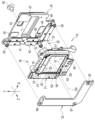
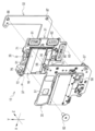
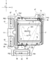
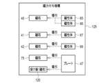
- FIG. 1 is a cross-sectional view taken along the line AA of FIG. It is a figure which shows the magnetic force applying mechanism. It is a front view of a movable member. It is a front view of the fixing member. It is sectional drawing which shows the mode which made the receiving plate of a ball a magnet. It is a figure which shows the magnetic force applying mechanism in the case of the aspect of FIG.
- the digital camera 2 includes a camera body 10.
- a lens mount 11 is provided on the front surface of the camera body 10.
- the lens mount 11 has a circular imaging aperture 12.
- An interchangeable imaging lens (not shown) is detachably attached to the lens mount 11.
- the digital camera 2 is an example of an "imaging apparatus" according to the technique of the present disclosure.
- the camera body 10 has a built-in anti-vibration device 15.
- the vibration isolator 15 is a device for correcting the blurring of the subject light due to the vibration applied to the camera body 10.
- the vibration applied to the camera body 10 includes camera shake of a user who holds the camera body 10 and shoots a subject.
- the image sensor 16 is mounted on the vibration isolator 15.
- the image sensor 16 is, for example, a CMOS (Complementary Metal Oxide Semiconductor) image sensor or a CCD (Charge Coupled Device) image sensor.
- the image pickup device 16 has a rectangular image pickup surface 17 for photographing a subject.
- the imaging surface 17 receives subject light indicating the subject.
- pixels that photoelectrically convert the received subject light and output an electric signal are arranged in a two-dimensional manner. The entire imaging surface 17 is exposed to the outside through the imaging aperture 12.
- a CPU (Central Processing Unit) 18 is connected to the anti-vibration device 15.
- the CPU 18 controls the operation of the vibration isolator 15.
- the CPU 18 is an example of a "processor” according to the technique of the present disclosure.
- a ROM (Read Only Memory) and / or a RAM (Random Access Memory), which are memories, are connected to the CPU 18 via a bus line.
- a computer is composed of the CPU 18, the memory, and the bus line.
- the vibration isolator 15 moves the image sensor 16 under the control of the CPU 18. More specifically, the anti-vibration device 15 moves the image pickup element 16 in the X-axis direction and the Y-axis direction by the amount that cancels the blur in the direction that cancels the blur, and moves the image pickup element 16 in the X-axis direction and the Z-axis direction that is orthogonal to the Y-axis direction.
- the image pickup element 16 is rotated around.
- the X-axis direction is a direction parallel to the side 19 of the image pickup surface 17 of the image pickup element 16
- the Y-axis direction is a direction parallel to the side 20 intersecting the side 19 at an angle of 90 °.
- Side 19 is an example of the "first side” according to the technique of the present disclosure.
- the side 20 is an example of the “second side” according to the technique of the present disclosure.
- the word “orthogonal” includes not only the meaning of perfect orthogonality but also the meaning of substantially orthogonality including errors allowed in design and manufacturing.
- the word “parallel” includes not only the meaning of perfect parallelism but also the meaning of substantially parallelism including errors allowed in design and manufacturing.
- the side of the side 19 is expressed as “down”, and the side opposite to the side 19 in the Y-axis direction is expressed as “up”. Further, the side of the side 20 is expressed as "left”, and the side opposite to the side 20 in the X-axis direction is expressed as "right”.
- blurring refers to a phenomenon caused by fluctuation of the optical axis OA with respect to a subject due to vibration.
- the “optical axis OA” refers to the optical axis of the subject light incident on the imaging surface 17 through the imaging lens.
- the fluctuation of the optical axis OA means, for example, that the optical axis OA is tilted due to the blurring with respect to the reference axis (for example, the optical axis OA before the blurring occurs).
- the blur correction includes not only the meaning of eliminating the blur but also the meaning of reducing the blur.
- the optical axis OA is parallel to the Z axis. That is, the Z-axis direction is an example of the "optical axis direction" according to the technique of the present disclosure.
- the vibration isolator 15 includes a fixing member 30, a movable member 31, and a yoke 32.
- the fixing member 30 is arranged on the back side of the camera body 10, and the yoke 32 is arranged on the front side of the camera body 10.
- the fixing member 30 is fixed to the camera body 10. Further, the fixing member 30 and the yoke 32 are fixed at intervals in the Z-axis direction.
- the movable member 31 is arranged between the fixing member 30 and the yoke 32 via three balls 35, balls 36, and balls 37 of the same size.
- the movable member 31 can be moved in the X-axis direction and the Y-axis direction with respect to the fixing member 30 and the yoke 32 by the balls 35 to 37, and can be rotated around the Z-axis. That is, the fixing member 30 is an example of "the other of the first member and the second member” according to the technique of the present disclosure. Further, the movable member 31 is an example of "one of the first member and the second member" according to the technique of the present disclosure.
- the fixing member 30 holds the magnet 40, the magnet 41, and the magnet 42.
- the fixing member 30 is an example of the "first member” according to the technique of the present disclosure.
- the magnets 40 to 42 are attached to the front surface of the fixing member 30 facing the movable member 31.
- Each of the magnets 40 to 42 is a set of a plate-shaped magnet having an N pole directed toward the movable member 31 side and a plate-shaped magnet having an S pole directed toward the movable member 31 side.
- the magnet 40 is arranged in the center of the lower part of the fixing member 30 so that its long side is along the X-axis direction.
- the magnet 41 and the magnet 42 are arranged along the Y-axis direction.
- the magnet 41 is arranged in the upper left corner of the fixing member 30 so that its long side is along the Y-axis direction.
- the magnet 42 is arranged in the lower left corner of the fixing member 30 so that its long side is along the Y-axis direction.
- the magnet 40 is an example of the "first magnet” according to the technique of the present disclosure.
- the magnet 41 and the magnet 42 are examples of the "second magnet” according to the technique of the present disclosure.
- a plate 45, a plate 46, and a plate 47 are attached to the front surface of the fixing member 30.
- the plate 45 is located in the lower center of the fixing member 30 and above the magnet 40.
- the plate 46 is located in the upper left corner of the fixing member 30 and is arranged to the right of the magnet 41.
- the plate 47 is located in the upper right corner of the fixing member 30.
- the plate 45 tumblably supports the ball 35, the plate 46 tumblably supports the ball 36, and the plate 47 tumblably supports the ball 37.
- the plate 47 is a magnetic material such as a thin iron plate.
- the plate 47 is an example of a "third magnetic material" according to the technique of the present disclosure.
- the fixed member 30 is formed with a square regulation opening 50 and a regulation opening 51 that regulate the movement range of the movable member 31 in the XY plane.
- the regulated opening 50 and the regulated opening 51 have substantially the same size when viewed in a plan view from the Z-axis direction.
- the regulation opening 50 is formed between the magnet 42 and the plate 45 in the lower left corner of the fixing member 30.
- the regulation opening 51 is formed on the left side of the plate 47 in the upper right corner of the fixing member 30. That is, the regulation opening 50 and the regulation opening 51 are arranged at substantially diagonal positions in the fixing member 30.
- the fixing member 30 is provided with a female screw 55, a female screw 56, and a female screw 57 via a spacer.
- the female screw 55 is provided in the lower right corner of the fixing member 30.
- the female screw 56 is provided in the upper left corner of the fixing member 30.
- the female screw 57 is provided in the lower left corner of the fixing member 30.
- the movable member 31 holds the image sensor 16 and holds the coil 60, the coil 61, and the coil 62.
- the movable member 31 is an example of the "second member" according to the technique of the present disclosure.
- the image sensor 16 is arranged at the center of the movable member 31.
- the coil 60 is located in the lower center of the movable member 31 at a position facing the magnet 40 in the Z-axis direction.
- the coil 61 is located in the upper left corner of the movable member 31 at a position facing the magnet 41 in the Z-axis direction.
- the coil 62 is located in the lower left corner of the movable member 31 at a position facing the magnet 42 in the Z-axis direction.
- the coil 60 is arranged so that its long side is along the X-axis direction.
- the coil 61 and the coil 62 are arranged along the Y-axis direction.
- the coil 61 and the coil 62 are arranged so that their long sides are along the Y-axis direction, respectively.
- the coil 60 is an example of the "first coil” according to the technique of the present disclosure.
- the coil 61 and the coil 62 are examples of the "second coil” according to the technique of the present disclosure.
- the front side of the coils 60 to 62 is covered with the protective film 63.
- a magnetic body 65, a magnetic body 66, a magnetic body 67, and a magnetic body 68 are attached to the protective film 63.
- the magnetic bodies 65 to 68 are, for example, thin plate pieces made of iron.
- the magnetic body 65 and the magnetic body 66 are arranged along the X-axis direction.
- the magnetic body 65 is arranged on the right end side of the coil 60, and the magnetic body 66 is arranged on the left end side of the coil 60.
- the magnetic body 67 and the magnetic body 68 are arranged along the Y-axis direction.
- the magnetic body 67 is arranged on the upper end side of the coil 61, and the magnetic body 68 is arranged on the lower end side of the coil 62.
- the magnetic body 65 and the magnetic body 66 are also arranged at positions facing the magnet 40 in the Z-axis direction. Therefore, the magnetic body 65 and the magnetic body 66 are attracted to the magnet 40. That is, the magnet 40, the magnetic body 65, and the magnetic body 66 act as magnetic springs.
- the magnetic material 65 and the magnetic material 66 are examples of the "first magnetic material" according to the technique of the present disclosure.
- the magnetic body 67 is also arranged at a position facing the magnet 41 in the Z-axis direction. Therefore, the magnetic body 67 is attracted to the magnet 41. That is, the magnet 41 and the magnetic body 67 also act as magnetic springs.
- the magnetic body 68 is also arranged at a position facing the magnet 42 in the Z-axis direction. Therefore, the magnetic body 68 is attracted to the magnet 42. That is, the magnet 42 and the magnetic body 68 also act as magnetic springs.
- the magnetic material 67 and the magnetic material 68 are examples of the “second magnetic material” according to the technique of the present disclosure.
- a recess 70, a recess 71, and a recess 72 are formed on the back surface of the movable member 31 facing the fixing member 30.
- the recess 70 is located in the lower center of the movable member 31 at a position facing the plate 45 in the Z-axis direction.
- the recess 71 is the upper left corner of the movable member 31 and is arranged at a position facing the plate 46 in the Z-axis direction.
- the recess 72 is the upper right corner of the movable member 31 and is arranged at a position facing the plate 47 in the Z-axis direction.
- the recess 70 accommodates the ball 35 in a rollable manner
- the recess 71 accommodates the ball 36 in a rollable manner
- the recess 72 accommodates the ball 37 in a rollable manner.
- the size of the recesses 70 to 72 when viewed in a plan view from the Z-axis direction is one size larger than the diameter of the balls 35 to 37. Further, the depth of the recesses 70 to 72 in the Z-axis direction is slightly smaller than the diameter of the balls 35 to 37 (see FIG. 5).
- a magnet 75 is attached to the back surface of the movable member 31.
- the magnet 75 is arranged at a position facing the magnetic bodies 65 to 68 with the image sensor 16 in between when viewed in a plan view from the Z-axis direction.
- the magnet 75 is arranged in the central portion of the diagonal region sandwiching the image pickup device 16 with respect to the substantially L-shaped arrangement region of the magnetic bodies 65 to 68 along the X-axis direction and the Y-axis direction.
- the magnet 75 is formed by a line parallel to the X-axis direction connecting the magnetic body 65 and the magnetic body 66 and a line parallel to the Y-axis direction connecting the magnetic body 67 and the magnetic body 68.
- the image pickup element 16 is arranged at the corners on the diagonal side of the corners.
- the magnet 75 is an example of a “third magnet” according to the technique of the present disclosure.
- the magnet 75 is arranged adjacent to the recess 72.
- the magnet 75 is arranged at a position facing the plate 47 in the Z-axis direction. Therefore, the plate 47 is attracted to the magnet 75. That is, the plate 47 and the magnet 75 also act as magnetic springs.
- adjacent as used herein means that the distance in the XY plane is, for example, within 1 cm.
- a columnar protrusion 80 protruding toward the fixing member 30 is provided at a position facing the regulation opening 50 in the Z-axis direction.
- a female screw 81 is formed at a position facing the regulation opening 51 in the Z-axis direction.
- the protrusion 80 is inserted through the regulation opening 50.
- a male screw 82 is fastened and fixed to the female screw 81.
- the male screw 82 is inserted into the regulation opening 51 and then attached to the female screw 81. Therefore, the protrusion 80 and the male screw 82 act as a regulating pin for restricting the movement of the movable member 31 in the XY plane.
- the yoke 32 is a magnetic material such as a thin plate made of iron, and has a substantially L shape following the arrangement of the magnets 40 to 42 and the coils 60 to 62.
- the yoke 32 forms a magnetic circuit with the magnets 40 to 42, and increases the magnetic flux received by the coils 60 to 62.
- a male screw 85, a male screw 86, and a male screw 87 are attached to the yoke 32.
- the male screws 85 to 87 are fastened and fixed to the female screws 55 to 57 of the fixing member 30. As a result, the fixing member 30 and the yoke 32 are fixed.
- the anti-vibration device 15 includes a pair of voice coil motors (VCM; Voice Coil Motor).
- VCM voice coil motors
- the pair of VCMs is a pair of a first VCM and a second VCM.
- the first VCM includes a pair of a magnet 40 and a coil 60, and a yoke 32, and generates power for moving the movable member 31 in the Y-axis direction.
- the second VCM includes a pair of a magnet 41 and a coil 61, a pair of a magnet 42 and a coil 62, and a yoke 32, and generates power for moving the movable member 31 in the X-axis direction.
- the first VCM generates a power to move the movable member 31 in the Y-axis direction by the magnetic force of the magnet 40 and the current flowing through the coil 60.
- the second VCM generates a force for moving the movable member 31 in the X-axis direction by the magnetic force of the magnet 41 and the current flowing through the coil 61, and the magnetic force of the magnet 42 and the current flowing through the coil 62.
- VCM when it is not necessary to distinguish between the first VCM and the second VCM, it is simply referred to as "VCM".
- the movable member 31 is provided with a Hall element that detects the position of the movable member 31, a temperature sensor that measures the temperature around the Hall element, and the like.
- the CPU 18 takes a difference between the position of the movable member 31 detected by the Hall element and the target position of the movable member 31 for correcting the blur, and performs feedback control for driving the VCM so as to eliminate the difference.
- the difference is large, the power due to VCM is relatively large, and conversely, when the difference is small, the power due to VCM is relatively small. Further, the CPU 18 corrects the temperature drift of the Hall element by using the temperature measured by the temperature sensor.
- the vibration isolator 15 includes a sliding mechanism 90, a sliding mechanism 91, and a sliding mechanism 92.
- the sliding mechanism 90 has a ball 35, a plate 45, and a recess 70.
- the sliding mechanism 91 has a ball 36, a plate 46, and a recess 71.
- the sliding mechanism 92 has a ball 37, a plate 47, and a recess 72 (see also FIG. 5).
- the sliding mechanisms 90 to 92 allow the movable member 31 to move with respect to the fixing member 30.
- FIG. 5 which is a cross-sectional view taken along the line AA of FIG. 1, the sliding mechanism 92 is arranged adjacent to the magnet 75, which is the third magnet. That is, the sliding mechanism 92 is an example of the "specific sliding mechanism" according to the technique of the present disclosure.
- a receiving plate 93 parallel to the XY plane is attached to the bottom surface of the recess 72.
- the ball 37 is rotatably sandwiched between the receiving plate 93 and the plate 47.
- the vibration isolator 15 includes a magnetic force applying mechanism 100.
- the magnetic force applying mechanism 100 includes magnets 40 to 42, magnets 75, magnetic bodies 65 to 68, and a plate 47.
- the magnetic force applying mechanism 100 applies a magnetic force that attracts the movable member 31 to the fixed member 30 in the Z-axis direction.
- the sliding mechanisms 90 to 92 are arranged at three locations between the fixed member 30 and the movable member 31. Therefore, the figure formed by the outline 110 connecting the arrangement position PA1 of the sliding mechanism 90, the arrangement position PA2 of the sliding mechanism 91, and the arrangement position PA3 of the sliding mechanism 92 is, of course, a triangle.
- the arrangement positions PA1 to PA3 are, for example, the positions of the centers of the recesses 70 to 72 in the XY plane.
- the center of gravity CE1 of the figure formed by the outline 110 is located at the center of the upper part of the imaging surface 17.
- the figure formed by the outline 111 connecting the arrangement position PB1 of the magnetic body 65, the arrangement position PB2 of the magnetic body 66, the arrangement position PB3 of the magnetic body 67, the arrangement position PB4 of the magnetic body 68, and the arrangement position PB5 of the plate 47 , This is also a pentagon, of course.
- the arrangement positions PB1 to PB5 are, for example, the positions of the magnetic bodies 65 to 68 and the center of gravity of the plate 47.
- the center of gravity CE2 of the figure formed by the outline 111 is located in the upper center of the imaging surface 17 like the center of gravity CE1.
- the placement positions PB1 to PB5 are examples of "placement positions of the first magnetic body, the second magnetic body, and the third magnetic body” according to the technique of the present disclosure.
- the outer line 111 is an example of the “outer line connecting the arrangement positions of the first magnetic body, the second magnetic body, and the third magnetic body” according to the technique of the present disclosure.
- the center of gravity CE2 is an example of "the center of gravity of a figure formed by an outer line connecting the arrangement positions of the first magnetic body, the second magnetic body, and the third magnetic body” according to the technique of the present disclosure.
- the point of action POA of the magnetic force given by the magnetic force applying mechanism 100 coincides with the center of gravity CE2.
- the action point POA of the magnetic force given by the magnetic force applying mechanism 100 is the attractive force of the magnet 40 to the magnetic body 65 and 66, the attractive force of the magnet 41 to the magnetic body 67, the attractive force of the magnet 42 to the magnetic body 68, and This is the point of action of the resultant force of the attractive force with respect to the plate 47 of the magnet 75.
- the center of gravity CE2 and the point of action POA may be different from each other.
- the center of gravity CE2 is located within the outline 110 when viewed in a plan view from the Z-axis direction. Similarly, when viewed in a plan view from the Z-axis direction, the point of action POA exists within the outline 110. Further, when viewed in a plan view from the Z-axis direction, the center of gravity CE1 and the center of gravity CE2 are adjacent to each other. Similarly, when viewed in a plane from the Z-axis direction, the center of gravity CE1 and the point of action POA are adjacent to each other.
- FIG. 7 shows the movable member 31 in a state where the protective film 63 has been removed.
- the broken line 115 indicates the rolling range of the ball 37.
- the broken line 116 indicates the moving range of the magnet 75.
- the rolling range 115 of the ball 37 and the moving range 116 of the magnet 75 have the same size as the regulation opening 50 and the regulation opening 51 when viewed in a plan view from the Z-axis direction.
- the plate 47 has a size that covers the rolling range 115 of the ball 37 and also covers the moving range 116 of the magnet 75 when viewed in a plan view from the Z-axis direction.
- the moving range 116 of the magnet 75 is an example of the “moving range of the third magnet” according to the technique of the present disclosure.
- the movable member 31 can be moved with respect to the fixing member 30 and the yoke 32 by the sliding mechanisms 90 to 92 arranged at three positions.
- the movable member 31 holds the image sensor 16. Therefore, the image sensor 16 also moves with the movement of the movable member 31.
- the movable member 31 is moved in the direction of canceling the blur by the amount of canceling the blur.
- the sliding mechanisms 90 to 92 arranged at three places can improve the movement stability of the movable member 31, and as a result, the image sensor The movement stability of 16 can be improved.
- the sliding mechanisms 90 to 92 are arranged at positions as far apart as possible.
- the sliding mechanisms 90 to 92 are provided on the fixing member 30 and the balls 35 to 37 that roll between the fixing member 30 and the movable member 31, and the balls 35 to 37. It includes plates 45 to 47 that support the rolling of the ball, and recesses 70 to 72 that are provided in the movable member 31 and accommodate the balls 35 to 37 so as to be rollable.
- the movable member 31 can be moved with a small amount of power as compared with the configuration in which the balls 35 to 37 are not used.
- the fixing member 30 is provided with magnets 40 to 42.
- the movable member 31 is provided with coils 60 to 62 at positions facing the magnets 40 to 42 in the Z-axis direction.
- the movable member 31 moves in the Y-axis direction by receiving the power generated by the first VCM described above. Further, the movable member 31 moves in the X-axis direction by receiving the power generated by the above-mentioned second VCM. In this way, in the vibration isolator 15, the movable member 31 can be moved with a simple configuration.
- the magnetic force applying mechanism 100 shown in FIG. 6 applies a magnetic force for attracting the movable member 31 to the fixed member 30 in the Z-axis direction.
- the movable member 31 is urged toward the fixed member 30, and the rattling of the movable member 31 in the Z-axis direction is eliminated.
- the magnetic force applying mechanism 100 includes a set of a magnet 75 and a plate 47 attracted by the magnet 75, in addition to a set of the magnets 40 to 42 and a magnetic material 65 to 68 attracted by the magnets 40 to 42.
- the magnet 75 is arranged at a position facing the magnetic bodies 65 to 68 with the image sensor 16 in between when viewed in a plan view from the Z-axis direction. Therefore, the balance of the attractive force in the Z-axis direction is improved as compared with the case where the magnetic force applying mechanism 100 is formed only by the combination of the magnets 40 to 42 and the magnetic bodies 65 to 68 attracted by the magnets 40 to 42. be able to. Therefore, the operational stability of the anti-vibration device 15 can be improved, and as a result, the operational stability of the digital camera 2 in which the anti-vibration device 15 is built can be enhanced.
- the plate 47 of the sliding mechanism 92 is also used as a third magnetic material attracted by the magnet 75. Therefore, the number of parts can be reduced.
- the magnetic bodies 65 to 68 and the arrangement positions PB1 of the plates 47 are within the outline 110 connecting the arrangement positions PA1 to PA3 of the sliding mechanisms 90 to 92.
- the center of gravity CE2 of the figure formed by the outline 111 connecting the PB5 is located.
- the action point POA of the magnetic force given by the magnetic force applying mechanism 100 exists in the outer line 110 connecting the arrangement positions PA1 to PA3 of the sliding mechanisms 90 to 92. Therefore, the balance of the suction force in the Z-axis direction can be improved.
- the center of gravity CE1 of the figure formed by the outer line 110 connecting the arrangement positions PA1 to PA3 of the sliding mechanisms 90 to 92 and the magnetic material. 65 to 68 and the center of gravity CE2 of the figure formed by the outline 111 connecting the arrangement positions PB1 to PB5 of the plate 47 are adjacent to each other.
- the center of gravity CE1 of the figure formed by the outer line 110 connecting the arrangement positions PA1 to PA3 of the sliding mechanisms 90 to 92 and the point of action POA of the magnetic force given by the magnetic force applying mechanism 100 And are adjacent.
- the balance of the suction force in the Z-axis direction can be further improved.
- the plate 47 of the sliding mechanism 92 has a size that covers the moving range 116 of the magnet 75 in addition to the rolling range 115 of the ball 37 when viewed in a plan view from the Z-axis direction. .. Therefore, when the magnet 75 moves with the movement of the movable member 31, there is no possibility that the plate 47 and the magnet 75 do not face each other in the Z-axis direction. Therefore, it is possible to avoid a situation in which the attractive force of the magnet 75 acting on the plate 47 changes depending on the moving position of the magnet 75 and the balance of the attractive force in the Z-axis direction is lost.
- the magnet 75 is arranged on the movable member 31, and the plate 47 is arranged on the fixed member 30. Since the movable member 31 is equipped with the image pickup element 16, the arrangement space is limited, but the fixed member 30 has a relatively large arrangement space. Therefore, the plate 47 can be widened.
- the CPU 18 has been exemplified as a processor that controls the operation of the vibration isolator 15, but the present invention is not limited to this.
- a programmable logic device Programmable Logic Device: PLD
- PLD Programmable Logic Device
- FPGA Field Programmable Gate Array
- ASIC Application Specific Circuit
- the receiving plate 120 attached to the recess 72 of the sliding mechanism 92 may be used as a magnet, and the plate 47 may be attracted by the receiving plate 120 in addition to the magnet 75.
- the magnetic force applying mechanism 125 includes the magnets 40 to 42, the magnets 75, the magnetic bodies 65 to 68, and the plate 47 of the magnetic force applying mechanism 100 shown in FIG. 6, as well as the receiving plate 120. Including further. That is, the receiving plate 120 is an example of the "fourth magnet" according to the technique of the present disclosure.
- the magnetic force applying mechanism 125 further includes a receiving plate 120 which is a magnet different from the magnet 75.
- the receiving plate 120 is arranged at a position facing the plate 47 of the sliding mechanism 92, and sucks the plate 47. Therefore, the balance of the attractive force in the Z-axis direction can be improved as compared with the case where only the magnet 75 is used.
- the plate 45 and the plate 46 may also be made of magnetic material, and magnets for attracting the plate 45 and the plate 46 may be provided in the recesses 70 and 71 of the sliding mechanism 90 and the sliding mechanism 91.
- the plates 45 to 47 of the sliding mechanisms 90 to 92 are provided in the fixing member 30, and the recesses 70 to 72 are provided in the movable member 31, but the present invention is not limited to this.
- the plates 131 to 133 corresponding to the plates 45 to 47 may be provided on the movable member 31, and the recesses 134 to 136 corresponding to the recesses 70 to 72 may be provided on the fixed member 30. ..
- the fixing member 30 is an example of "one of the first member and the second member” according to the technique of the present disclosure
- the movable member 31 is the "first member and the second member” according to the technique of the present disclosure. This is an example of "the other of the members”.
- magnets 40 to 42 are provided on the fixing member 30, and coils 60 to 62 are provided on the movable member 31, but the present invention is not limited to this.
- magnets 141 to 143 corresponding to magnets 40 to 42 may be provided on the movable member 31, and coils 144 to 146 corresponding to coils 60 to 62 may be provided on the fixed member 30. ..
- the magnetic bodies 147 to 150 corresponding to the magnetic bodies 65 to 68 are provided on the fixing member 30.
- the fixing member 30 is an example of the "second member” according to the technique of the present disclosure
- the movable member 31 is an example of the "first member” according to the technique of the present disclosure.
- the anti-vibration device 160 of the second embodiment shown in FIGS. 13 and 14 is built in an image pickup device such as a digital camera 2 as in the first embodiment.
- the image sensor 161 is mounted on the anti-vibration device 160, similarly to the anti-vibration device 15 and the like according to the first embodiment.
- the vibration isolator 160 moves the image pickup element 161 in the X-axis direction and the Y-axis direction by the amount of the shake-canceling direction in the direction of canceling the blur, and the image pickup element is rotated in the Z-axis direction orthogonal to the X-axis direction and the Y-axis direction. Rotate 161.
- the X-axis direction is a direction parallel to the side 163 of the image pickup surface 162 of the image pickup element 161 and the Y-axis direction is a direction parallel to the side 164 that intersects the side 163 at an angle of 90 °.
- Side 163 is an example of the "first side” according to the technique of the present disclosure.
- the side 164 is an example of the "second side” according to the technique of the present disclosure.
- the side of the side 163 is expressed as “upper”, and the side opposite to the side 163 in the Y-axis direction is expressed as “lower”. Further, the side of the side 164 is expressed as “left”, and the side opposite to the side 164 in the X-axis direction is expressed as "right”.
- the vibration isolator 160 includes a fixing member 170, a movable member 171 and a yoke 172.
- the movable member 171 is arranged between the fixing member 170 and the yoke 172 via balls 175, balls 176, and balls 177 of the same size.
- the movable member 171 can be moved in the X-axis direction and the Y-axis direction with respect to the fixing member 170 and the yoke 172 by the balls 175 to 177, and can be rotated around the Z-axis.
- the fixing member 170 is an example of "the other of the first member and the second member” according to the technique of the present disclosure.
- the movable member 171 is an example of "one of the first member and the second member” according to the technique of the present disclosure.
- the fixing member 170 holds a magnet 180, a magnet 181 and a magnet 182.
- the fixing member 170 is an example of the "first member” according to the technique of the present disclosure.
- the magnets 180 to 182 are attached to the front surface of the fixing member 170 facing the movable member 171.
- Each of the magnets 180 to 182 is a set of a plate-shaped magnet having an N pole directed toward the movable member 171 side and a plate-shaped magnet having an S pole directed toward the movable member 171 side.
- the magnet 180 is arranged in the center of the upper part of the fixing member 170 so that its long side is along the X-axis direction.
- the magnets 181 and 182 are arranged along the Y-axis direction.
- the magnet 181 is arranged in the upper left corner of the fixing member 170 so that its long side is along the Y-axis direction.
- the magnet 182 is arranged in the lower left corner of the fixing member 170 so that its long side is along the Y-axis direction.
- the magnet 180 is an example of the "first magnet” according to the technique of the present disclosure. Further, the magnet 181 and the magnet 182 are examples of the "second magnet” according to the technique of the present disclosure.
- Reference numeral 183 is a magnet used for a Hall element (not shown).
- plates 185, plate 186, and plate 187 are attached to the front surface of the fixing member 170.
- the plate 185 is arranged between the magnet 182 and the magnet 183 in the lower center of the fixing member 170.
- the plate 186 is the upper left corner of the fixing member 170 and is located below the magnet 181.
- the plate 187 is located in the upper right corner of the fixing member 170 and is located to the right of the magnet 180.
- the plate 185 supports the rolling of the ball 175, the plate 186 supports the rolling of the ball 176, and the plate 187 supports the rolling of the ball 177.
- a magnet 188 is attached between the magnet 183 and the plate 185.
- the magnet 188 is arranged adjacent to the plate 185.
- the term "adjacent" as used herein means that the distance in the XY plane is, for example, within 1 cm.
- the magnet 188 is an example of a "third magnet” according to the technique of the present disclosure. That is, in the second embodiment, the third magnet is arranged on the fixing member 170.
- the fixed member 170 is formed with a square-shaped regulation opening 190 that regulates the movement range of the movable member 171 in the XY plane.
- the regulation opening 190 is formed between the magnet 182 and the plate 186 in the lower left corner of the fixing member 170.
- the fixing member 170 is provided with a female screw 195 and a female screw 196 via a spacer.
- the female screw 195 is provided in the lower center of the fixing member 170, and the female screw 196 is provided in the upper right corner of the fixing member 170.
- the movable member 171 holds the image sensor 161 and holds the coil 200, the coil 201, and the coil 202.
- the movable member 171 is an example of the "second member" according to the technique of the present disclosure.
- the image sensor 161 is arranged at the center of the movable member 171.
- the coil 200 is located in the upper center of the movable member 171 and at a position facing the magnet 180 in the Z-axis direction.
- the coil 201 is located in the upper left corner of the movable member 171 at a position facing the magnet 181 in the Z-axis direction.
- the coil 202 is located in the lower left corner of the movable member 171 at a position facing the magnet 182 in the Z-axis direction.
- the coil 200 is arranged so that its long side is along the X-axis direction.
- the coil 201 and the coil 202 are arranged along the Y-axis direction.
- the coil 201 and the coil 202 are arranged so that their long sides are along the Y-axis direction, respectively.
- the coil 200 is an example of the "first coil” according to the technique of the present disclosure.
- the coil 201 and the coil 202 are examples of the "second coil” according to the technique of the present disclosure.
- a magnetic body 205, a magnetic body 206, and a magnetic body 207 are attached to the front surface of the movable member 171 facing the yoke 172.
- the magnetic bodies 205 to 207 are, for example, thin plate pieces made of iron, like the magnetic materials 65 to 68.
- the magnetic body 205 is arranged in the center of the coil 200.
- the magnetic material 206 and the magnetic material 207 are arranged along the Y-axis direction.
- the magnetic body 206 is arranged on the lower end side of the coil 201, and the magnetic body 207 is arranged on the upper end side of the coil 202.
- the magnetic body 205 Since the coil 200 is arranged at a position facing the magnet 180 in the Z-axis direction as described above, the magnetic body 205 is also arranged at a position facing the magnet 180 in the Z-axis direction. Therefore, the magnetic material 205 is attracted to the magnet 180. That is, the magnet 180 and the magnetic body 205 act as magnetic springs.
- the magnetic material 205 is an example of the "first magnetic material" according to the technique of the present disclosure.
- the magnetic body 206 is also arranged at a position facing the magnet 181 in the Z-axis direction. Therefore, the magnetic material 206 is attracted to the magnet 181. That is, the magnet 181 and the magnetic body 206 also act as magnetic springs.
- the magnetic body 207 is also arranged at a position facing the magnet 182 in the Z-axis direction. Therefore, the magnetic material 207 is attracted to the magnet 182. That is, the magnet 182 and the magnetic body 207 also act as magnetic springs.
- the magnetic material 206 and the magnetic material 207 are examples of the "second magnetic material" according to the technique of the present disclosure.
- a recess 210, a recess 211, and a recess 212 are formed on the back surface of the movable member 171 facing the fixing member 170.
- the recess 210 is located in the lower center of the movable member 171 and at a position facing the plate 185 in the Z-axis direction.
- the recess 211 is the upper left corner of the movable member 171 and is arranged at a position facing the plate 186 in the Z-axis direction.
- the recess 212 is the upper right corner of the movable member 171 and is arranged at a position facing the plate 187 in the Z-axis direction.
- the recess 210 accommodates the ball 175 in a rollable manner
- the recess 211 accommodates the ball 176 in a rollable manner
- the recess 212 accommodates the ball 177 in a rollable manner.
- the size of the recesses 210 to 212 when viewed in a plan view from the Z-axis direction is one size larger than the diameter of the balls 175 to 177. Further, the depth of the recesses 210 to 212 in the Z-axis direction is slightly smaller than the diameter of the balls 175 to 177.
- a magnetic body 215 is attached to a portion of the movable member 171 that faces the magnet 188 in the Z-axis direction.
- the magnetic body 215 and the magnet 188 are arranged at positions facing the magnetic bodies 205 to 207 with the image pickup element 161 in between when viewed in a plan view from the Z-axis direction.
- the magnet 188 is arranged in the central portion of the diagonal region sandwiching the image sensor 161 with respect to the substantially L-shaped arrangement region of the magnetic bodies 205 to 207 along the X-axis direction and the Y-axis direction. Has been done.
- the magnet 188 passes through the arrangement position of the magnetic body 205 (for example, the position of the center of gravity of the magnetic body 205) and is parallel to the X-axis direction, and in the Y-axis direction connecting the magnetic body 206 and the magnetic body 207. It is arranged at the corners on the diagonal side of the image pickup element 161 with respect to the corners formed by the parallel lines.
- the magnetic body 215 is arranged at a position facing the magnet 188 in the Z-axis direction as described above. Therefore, the magnetic material 215 is attracted to the magnet 188. That is, the magnet 188 and the magnetic body 215 also act as magnetic springs.
- the magnetic material 215 is an example of the "third magnetic material" according to the technique of the present disclosure.
- a columnar protrusion 220 protruding toward the fixing member 170 is provided at a position facing the regulation opening 190 in the Z-axis direction.
- the protrusion 220 is inserted through the regulation opening 190. Therefore, the protrusion 220 acts as a regulation pin that regulates the movement of the movable member 171 in the XY plane.
- the yoke 172 is a magnetic material such as a thin plate made of iron, and has a substantially L-shape following the arrangement of the magnets 180 to 182 and the coils 200 to 202.
- the yoke 172 forms a magnetic circuit between the magnets 180 to 182 and increases the magnetic flux received by the coils 200 to 202.
- the yoke 172 is provided with a pair of guards 222 and guards 223 that regulate the movement of the movable member 171 in the XY plane.
- the guard 222 and the guard 223 project from the back surface of the yoke 172 facing the movable member 171 toward the movable member 171.
- a male screw 225 and a male screw 226 are attached to the yoke 172.
- the male screw 225 and the male screw 226 are fastened and fixed to the female screw 195 and the female screw 196 of the fixing member 170. As a result, the fixing member 170 and the yoke 172 are fixed.
- the anti-vibration device 160 includes a pair of voice coil motors (VCM; Voice Coil Motor).
- the pair of VCMs according to the second embodiment is a pair of a third VCM and a fourth VCM.
- the third VCM includes a pair of a magnet 180 and a coil 200, and a yoke 172, and generates power for moving the movable member 171 in the Y-axis direction.
- the fourth VCM includes a pair of a magnet 181 and a coil 201, a pair of a magnet 182 and a coil 202, and a yoke 172, and generates a power for moving the movable member 171 in the X-axis direction.
- the third VCM generates a power to move the movable member 171 in the Y-axis direction by the magnetic force of the magnet 180 and the current flowing through the coil 200. Further, the fourth VCM generates a force for moving the movable member 171 in the X-axis direction by the magnetic force of the magnet 181 and the current flowing through the coil 201, and the magnetic force of the magnet 182 and the current flowing through the coil 202.
- the vibration isolator 160 includes a sliding mechanism 230, a sliding mechanism 231 and a sliding mechanism 232.
- the sliding mechanism 230 has a ball 175, a plate 185, and a recess 210.
- the sliding mechanism 231 has a ball 176, a plate 186, and a recess 211.
- the sliding mechanism 232 has a ball 177, a plate 187, and a recess 212.
- the sliding mechanisms 230 to 232 allow the movable member 171 to move with respect to the fixing member 170.
- the sliding mechanism 230 is arranged adjacent to the magnet 188, which is the third magnet. That is, the sliding mechanism 230 is an example of the "specific sliding mechanism" according to the technique of the present disclosure.
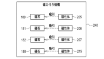
- the vibration isolator 160 includes a magnetic force applying mechanism 240.
- the magnetic force applying mechanism 240 has magnets 180 to 182, magnets 188, magnetic bodies 205 to 207, and magnetic body 215.
- the magnetic force applying mechanism 240 applies a magnetic force that attracts the movable member 171 to the fixed member 170 in the Z-axis direction.
- the magnet 75 which is the third magnet
- the plate 47 which is the third magnetic material
- the magnet 188 which is the third magnet
- the magnetic body 215, which is the third magnetic material is arranged on the movable member 171. Therefore, for example, the following effects are exhibited.
- a shutter mechanism 250 is arranged in front of the front of the vibration isolator 160.
- the shutter mechanism 250 includes a main body frame 251, a mechanical operation unit 252, and a motor 253.
- a shutter opening corresponding to the image pickup surface 162 of the image pickup device 161 is formed in the center of the main body frame 251, and a light-shielding curtain 254 is attached to the shutter opening.
- the light-shielding curtain 254 has a front curtain (not shown) and a rear curtain (not shown). That is, the shutter mechanism 250 is a focal plane shutter mechanism.
- the mechanical operation unit 252 and the motor 253 are attached to the back surface of the main body frame 251 facing the vibration isolator 160.
- the mechanical operation unit 252 is equipped with various mechanical parts such as gears, springs, and chains for moving the light-shielding curtain 254.
- the motor 253 applies a rotational driving force to the mechanical operation unit 252.
- the motor 253 is arranged adjacent to the magnet 188.
- the exterior of the motor 253 is formed of a magnetic material such as iron.
- the magnet 188 and the motor 253 whose exterior or the like is formed of a magnetic material are arranged adjacent to each other, if the magnet 188 is arranged not on the fixed member 170 but on the movable member 171, it is movable.
- the movement of the member 171 may cause the magnet 188 and the motor 253 to be attracted to each other, which may hinder the movement of the movable member 171.
- the magnet 188 is arranged on the fixed member 170, and the arrangement position of the magnet 188 does not move. Therefore, the magnet 188 and the motor 253 are attracted to each other, so that the movable member 171 There is no risk of hindering movement.
- the motor 253 of the shutter mechanism 250 is mentioned as a magnetic material that may be attracted to the magnet 188, but the present invention is not limited to this. It may be a mechanical moving part of a diaphragm mechanism or a motor of a diaphragm mechanism. Further, a motor that generates power for moving a lens, for example, a zoom lens may be used.
- the plate corresponding to the plates 185 to 187 may be provided in the movable member 171 and the recesses corresponding to the recesses 210 to 212 may be provided in the fixing member 170.
- magnets corresponding to magnets 180 to 182 may be provided on the movable member 171 and coils corresponding to the coils 200 to 202 may be provided on the fixing member 170.
- the number of sliding mechanisms is not limited to three, and may be four or more.
- the anti-vibration device of the present disclosure can be applied to an imaging device other than the illustrated digital camera, for example, a smartphone, a tablet terminal, a surveillance camera, or the like.
- the technique of the present disclosure can be appropriately combined with the various embodiments described above and / or various modifications.
- various configurations can be adopted as long as they do not deviate from the gist.
- the technique of the present disclosure extends to a storage medium for storing the program non-temporarily in addition to the program.
- a and / or B is synonymous with "at least one of A and B". That is, “A and / or B” means that it may be A alone, B alone, or a combination of A and B. Further, in the present specification, when three or more matters are connected and expressed by "and / or", the same concept as “A and / or B" is applied.
Landscapes
- Engineering & Computer Science (AREA)
- Physics & Mathematics (AREA)
- General Physics & Mathematics (AREA)
- Multimedia (AREA)
- Signal Processing (AREA)
- Power Engineering (AREA)
- Adjustment Of Camera Lenses (AREA)
- Studio Devices (AREA)
- Camera Bodies And Camera Details Or Accessories (AREA)
Priority Applications (1)
| Application Number | Priority Date | Filing Date | Title |
|---|---|---|---|
| JP2021572979A JP7371131B2 (ja) | 2020-01-24 | 2020-11-12 | 防振装置、および撮像装置 |
Applications Claiming Priority (2)
| Application Number | Priority Date | Filing Date | Title |
|---|---|---|---|
| JP2020010376 | 2020-01-24 | ||
| JP2020-010376 | 2020-01-24 |
Publications (1)
| Publication Number | Publication Date |
|---|---|
| WO2021149339A1 true WO2021149339A1 (ja) | 2021-07-29 |
Family
ID=76993357
Family Applications (1)
| Application Number | Title | Priority Date | Filing Date |
|---|---|---|---|
| PCT/JP2020/042307 Ceased WO2021149339A1 (ja) | 2020-01-24 | 2020-11-12 | 防振装置、および撮像装置 |
Country Status (2)
| Country | Link |
|---|---|
| JP (1) | JP7371131B2 (https=) |
| WO (1) | WO2021149339A1 (https=) |
Cited By (2)
| Publication number | Priority date | Publication date | Assignee | Title |
|---|---|---|---|---|
| WO2024053255A1 (ja) * | 2022-09-06 | 2024-03-14 | 富士フイルム株式会社 | 像ブレ補正装置及び撮像装置 |
| WO2025004952A1 (ja) * | 2023-06-30 | 2025-01-02 | ソニーグループ株式会社 | 交換レンズ及び撮像装置 |
Citations (2)
| Publication number | Priority date | Publication date | Assignee | Title |
|---|---|---|---|---|
| JP2008152034A (ja) * | 2006-12-18 | 2008-07-03 | Tamron Co Ltd | アクチュエータ、及びそれを備えたレンズユニット、カメラ |
| JP2010231168A (ja) * | 2009-03-04 | 2010-10-14 | Ricoh Co Ltd | 像振れ補正装置、レンズ鏡筒、撮像装置および携帯情報端末 |
Family Cites Families (1)
| Publication number | Priority date | Publication date | Assignee | Title |
|---|---|---|---|---|
| JP7086646B2 (ja) * | 2018-03-05 | 2022-06-20 | キヤノン株式会社 | ステージ装置、並びにステージ装置を備える撮像装置及びレンズ装置 |
-
2020
- 2020-11-12 WO PCT/JP2020/042307 patent/WO2021149339A1/ja not_active Ceased
- 2020-11-12 JP JP2021572979A patent/JP7371131B2/ja active Active
Patent Citations (2)
| Publication number | Priority date | Publication date | Assignee | Title |
|---|---|---|---|---|
| JP2008152034A (ja) * | 2006-12-18 | 2008-07-03 | Tamron Co Ltd | アクチュエータ、及びそれを備えたレンズユニット、カメラ |
| JP2010231168A (ja) * | 2009-03-04 | 2010-10-14 | Ricoh Co Ltd | 像振れ補正装置、レンズ鏡筒、撮像装置および携帯情報端末 |
Cited By (2)
| Publication number | Priority date | Publication date | Assignee | Title |
|---|---|---|---|---|
| WO2024053255A1 (ja) * | 2022-09-06 | 2024-03-14 | 富士フイルム株式会社 | 像ブレ補正装置及び撮像装置 |
| WO2025004952A1 (ja) * | 2023-06-30 | 2025-01-02 | ソニーグループ株式会社 | 交換レンズ及び撮像装置 |
Also Published As
| Publication number | Publication date |
|---|---|
| JPWO2021149339A1 (https=) | 2021-07-29 |
| JP7371131B2 (ja) | 2023-10-30 |
Similar Documents
| Publication | Publication Date | Title |
|---|---|---|
| CN212723615U (zh) | 相机模块 | |
| KR102550129B1 (ko) | 폴디드 모듈 및 이를 포함하는 휴대용 전자기기 | |
| US8369698B2 (en) | Image blur correction apparatus and camera | |
| CN108508678B (zh) | Ois摄像头模块及包括该ois摄像头模块的双摄像头系统 | |
| TWI569640B (zh) | 攝影模組 | |
| KR101643160B1 (ko) | 틸팅 방식 ois 카메라 모듈 | |
| CN114578631B (zh) | 相机模块 | |
| TW201331697A (zh) | 透鏡驅動裝置 | |
| TW201341941A (zh) | 影像抖動修正裝置以及透鏡驅動裝置 | |
| JP2020060726A (ja) | 撮像素子駆動装置、これを備えるカメラ装置及び電子機器 | |
| JP2021103271A (ja) | 手振れ補正機能付き撮像装置 | |
| CN103703412B (zh) | 成像装置 | |
| CN109661613B (zh) | 摄像元件驱动装置、摄像元件驱动装置的制造方法以及摄像装置 | |
| JP7371131B2 (ja) | 防振装置、および撮像装置 | |
| JP2008216877A5 (https=) | ||
| TWI461825B (zh) | 影像穩定模組及成像裝置 | |
| US12262114B2 (en) | Camera module with sensor shifting module | |
| TWM545928U (zh) | 雙鏡頭攝像模組 | |
| KR101603059B1 (ko) | 카메라 렌즈 모듈 | |
| WO2022180976A1 (ja) | 撮像素子ユニット、および撮像装置 | |
| JP5582922B2 (ja) | 像ブレ補正装置及び撮像装置 | |
| WO2017145205A1 (ja) | 像振れ補正装置、及び撮像装置 | |
| JP7680521B2 (ja) | 撮像素子ユニット、および撮像装置 | |
| JP2013073201A (ja) | 像振れ補正装置及びそれを備えた撮像装置 | |
| US12348845B2 (en) | Camera module |
Legal Events
| Date | Code | Title | Description |
|---|---|---|---|
| 121 | Ep: the epo has been informed by wipo that ep was designated in this application |
Ref document number: 20914778 Country of ref document: EP Kind code of ref document: A1 |
|
| ENP | Entry into the national phase |
Ref document number: 2021572979 Country of ref document: JP Kind code of ref document: A |
|
| NENP | Non-entry into the national phase |
Ref country code: DE |
|
| 122 | Ep: pct application non-entry in european phase |
Ref document number: 20914778 Country of ref document: EP Kind code of ref document: A1 |