WO2021145005A1 - 農作業車、自動走行制御プログラム、自動走行制御プログラムを記録した記録媒体、自動走行制御方法 - Google Patents
農作業車、自動走行制御プログラム、自動走行制御プログラムを記録した記録媒体、自動走行制御方法 Download PDFInfo
- Publication number
- WO2021145005A1 WO2021145005A1 PCT/JP2020/019722 JP2020019722W WO2021145005A1 WO 2021145005 A1 WO2021145005 A1 WO 2021145005A1 JP 2020019722 W JP2020019722 W JP 2020019722W WO 2021145005 A1 WO2021145005 A1 WO 2021145005A1
- Authority
- WO
- WIPO (PCT)
- Prior art keywords
- turning
- aircraft
- cross
- border
- boundary line
- Prior art date
- Legal status (The legal status is an assumption and is not a legal conclusion. Google has not performed a legal analysis and makes no representation as to the accuracy of the status listed.)
- Ceased
Links
Images




Classifications
-
- A—HUMAN NECESSITIES
- A01—AGRICULTURE; FORESTRY; ANIMAL HUSBANDRY; HUNTING; TRAPPING; FISHING
- A01B—SOIL WORKING IN AGRICULTURE OR FORESTRY; PARTS, DETAILS, OR ACCESSORIES OF AGRICULTURAL MACHINES OR IMPLEMENTS, IN GENERAL
- A01B69/00—Steering of agricultural machines or implements; Guiding agricultural machines or implements on a desired track
- A01B69/007—Steering or guiding of agricultural vehicles, e.g. steering of the tractor to keep the plough in the furrow
- A01B69/008—Steering or guiding of agricultural vehicles, e.g. steering of the tractor to keep the plough in the furrow automatic
-
- A—HUMAN NECESSITIES
- A01—AGRICULTURE; FORESTRY; ANIMAL HUSBANDRY; HUNTING; TRAPPING; FISHING
- A01B—SOIL WORKING IN AGRICULTURE OR FORESTRY; PARTS, DETAILS, OR ACCESSORIES OF AGRICULTURAL MACHINES OR IMPLEMENTS, IN GENERAL
- A01B69/00—Steering of agricultural machines or implements; Guiding agricultural machines or implements on a desired track
-
- G—PHYSICS
- G05—CONTROLLING; REGULATING
- G05D—SYSTEMS FOR CONTROLLING OR REGULATING NON-ELECTRIC VARIABLES
- G05D1/00—Control of position, course, altitude or attitude of land, water, air or space vehicles, e.g. using automatic pilots
- G05D1/20—Control system inputs
- G05D1/24—Arrangements for determining position or orientation
- G05D1/247—Arrangements for determining position or orientation using signals provided by artificial sources external to the vehicle, e.g. navigation beacons
- G05D1/248—Arrangements for determining position or orientation using signals provided by artificial sources external to the vehicle, e.g. navigation beacons generated by satellites, e.g. GPS
-
- G—PHYSICS
- G05—CONTROLLING; REGULATING
- G05D—SYSTEMS FOR CONTROLLING OR REGULATING NON-ELECTRIC VARIABLES
- G05D1/00—Control of position, course, altitude or attitude of land, water, air or space vehicles, e.g. using automatic pilots
- G05D1/40—Control within particular dimensions
- G05D1/43—Control of position or course in two dimensions [2D]
-
- G—PHYSICS
- G05—CONTROLLING; REGULATING
- G05D—SYSTEMS FOR CONTROLLING OR REGULATING NON-ELECTRIC VARIABLES
- G05D1/00—Control of position, course, altitude or attitude of land, water, air or space vehicles, e.g. using automatic pilots
- G05D1/60—Intended control result
- G05D1/648—Performing a task within a working area or space, e.g. cleaning
-
- B—PERFORMING OPERATIONS; TRANSPORTING
- B60—VEHICLES IN GENERAL
- B60Y—INDEXING SCHEME RELATING TO ASPECTS CROSS-CUTTING VEHICLE TECHNOLOGY
- B60Y2200/00—Type of vehicle
- B60Y2200/20—Off-Road Vehicles
- B60Y2200/22—Agricultural vehicles
-
- G—PHYSICS
- G05—CONTROLLING; REGULATING
- G05D—SYSTEMS FOR CONTROLLING OR REGULATING NON-ELECTRIC VARIABLES
- G05D2105/00—Specific applications of the controlled vehicles
- G05D2105/15—Specific applications of the controlled vehicles for harvesting, sowing or mowing in agriculture or forestry
-
- G—PHYSICS
- G05—CONTROLLING; REGULATING
- G05D—SYSTEMS FOR CONTROLLING OR REGULATING NON-ELECTRIC VARIABLES
- G05D2107/00—Specific environments of the controlled vehicles
- G05D2107/20—Land use
- G05D2107/21—Farming, e.g. fields, pastures or barns
-
- G—PHYSICS
- G05—CONTROLLING; REGULATING
- G05D—SYSTEMS FOR CONTROLLING OR REGULATING NON-ELECTRIC VARIABLES
- G05D2109/00—Types of controlled vehicles
- G05D2109/10—Land vehicles
Definitions
- the present invention relates to an automatically traveling agricultural work vehicle that travels in a field scene bounded by a boundary object.
- the agricultural work vehicle includes a measuring device that detects the position of the traveling machine using a satellite positioning system, an automatic running control unit that automatically runs the running machine along a set work running line, and a field scene and ridges. It is equipped with an automatic deceleration unit that stops the traveling aircraft when the traveling aircraft approaches the ridge line, which is the boundary line between the two.
- Agricultural work vehicles repeat forward traveling toward the boundary and turning (turning) when approaching the boundary in order to travel the entire field bounded by the boundary such as a shore.
- the aircraft may turn on a turning locus different from the assumed turning locus depending on the start timing of turning, the road surface condition in the field, the vehicle speed at the time of turning, and the like.
- an automatically traveling agricultural work vehicle such as Patent Document 1 makes a turn near the boundary line
- the machine turns closer to the boundary line than the assumed turning trajectory
- the position of the machine body reaches the boundary line and the machine body Makes an emergency stop. If the aircraft makes an emergency stop during automatic driving, it will be switched to manual operation, and it will be necessary to manually perform turning so as not to cross the boundary line. Since such cross-border avoidance turning running takes time and effort, the work is delayed.
- the farm work vehicle can automatically travel in a field scene bounded by a boundary object, and has a machine body position calculation unit that calculates the machine body position, which is the position of the machine body in the field scene, and the machine body and the above.
- the cross-border prevention control unit Based on the boundary line set to avoid contact with the boundary object and the position of the aircraft, the cross-border prevention control unit that prohibits the aircraft from traveling beyond the boundary line and the trajectory of the aircraft during turning travel. It includes a turning locus estimation unit that estimates a certain turning locus, and a turning cross-border determination unit that determines whether or not the aircraft crosses the boundary line in an actual turning running based on the estimated turning locus.
- the airframe when the airframe makes a turning run, the turning locus in the turning running is estimated in advance. Therefore, based on the estimated turning locus, the airframe makes the boundary line in the actual turning running. It is determined whether or not it exceeds.
- the estimation of the turning locus by the turning locus estimation unit and the determination by the cross-border determination unit at the time of turning can be performed before the actual turning running, during the actual turning running, or both. If it is determined that the aircraft crosses the boundary line, recovery measures are taken before the cross-border prevention control unit prohibits the aircraft from traveling. This recovery process can be either manual or automatic. Such a recovery measure is not only easier but also has the advantage of reducing time loss as compared with the case where the recovery action is performed after the cross-border prevention control unit prohibits the traveling of the aircraft.
- the recovery process is to cancel the scheduled turning run and perform cross-border avoidance turning running by moving the turning running start point or changing the turning radius before the aircraft crosses the boundary line. Therefore, in one of the preferred embodiments of the present invention, when the aircraft is determined by the turning cross-border determination unit to cross the boundary line, cross-border avoidance turning travel is performed.
- cross-border avoidance turning travel is to estimate the turning locus in turning using the maximum steering angle if the steering angle of the planned turning running is less than the maximum steering angle, and based on the estimated turning locus. If the result of the cross-border determination at the time of turning is good, it is possible to avoid crossing the boundary line by turning at the maximum steering angle. Therefore, in one of the preferred embodiments of the present invention, the cross-border avoidance turning run includes turning running at the maximum steering angle. In order to avoid crossing the boundary line more reliably, a direction change running (a kind of turning run) using reverse movement, which is generally called a turn-back run, is preferable. For this reason, in one of the preferred embodiments of the present invention, the cross-border avoidance turning run includes reverse movement.
- the field scene to be worked is divided into an outer peripheral area and an inner area located inside the outer peripheral area, and the work in the inner area is a straight running and a turn to perform the work. Therefore, it is repeated with a turning run (mainly a U-turn run) in which no work is performed. For this reason, it is not uncommon for the airframe to be temporarily stopped before shifting from straight running in the internal region to turning running in the outer peripheral region.
- the field scene is divided into an outer peripheral region along the boundary line and an inner region located inside the outer peripheral region.
- the automatic traveling work in the internal region is performed by repeating the straight traveling in the internal region and the turning traveling in the outer peripheral region, and the aircraft is temporarily stopped at the transition from the straight traveling to the turning traveling. During the pause, the turning locus is estimated and the cross-border determination at the time of turning is performed. As a result, the temporary stop of the aircraft that occurs at the time of transition from straight running to turning running can be effectively used.
- the term "straight running" used in the present invention does not mean only straight running, but also includes curved running that curves with a large radius of curvature.
- the airframe position calculation unit calculates the airframe position using satellite positioning, and the position of the boundary line is an orbit along the outermost periphery of the field scene. It is calculated based on the aircraft position (traveling locus) during traveling.
- the automatic travel control program is an automatic travel control program for an automatically traveling farm work vehicle traveling in a field scene bounded by a boundary object, and is a position of an airframe in the field scene. Based on the aircraft position calculation function that calculates the aircraft position, the boundary line set to avoid contact between the aircraft and the boundary object, and the aircraft position, the aircraft is prohibited from traveling beyond the boundary line.
- a cross-border prevention control function a turning locus estimation function that estimates a turning locus that is a locus of the aircraft during turning, and whether the aircraft crosses the boundary line in actual turning based on the estimated turning locus. Includes a cross-border judgment function when turning to determine whether or not.
- the recording medium on which the automatic travel control program according to the present invention is recorded is a recording medium on which an automatic travel control program for an automatically traveling farm work vehicle traveling in a field scene bounded by a boundary object is recorded.
- the aircraft is based on the aircraft position calculation function that calculates the aircraft position, which is the position of the aircraft in the field scene, and the boundary line and the aircraft position set to avoid contact between the aircraft and the boundary object.
- the automatic traveling control method is an automatic traveling control method for an agricultural work vehicle capable of automatically traveling in a field scene bounded by a boundary object, and is a position of an airframe in the field scene. Based on the aircraft position calculation step for calculating the aircraft position, the boundary line set to avoid contact between the aircraft and the boundary object, and the aircraft position, the aircraft is prohibited from traveling beyond the boundary line.
- a cross-border prevention control step, a turning locus estimation step that estimates a turning locus that is a locus of the aircraft during turning, and whether the aircraft crosses the boundary line in actual turning based on the estimated turning locus. Includes a turning cross-border determination step to determine whether or not.
- a passenger-type rice transplanter will be taken up and described below.
- This rice transplanter can automatically travel in a field scene bounded by a boundary object.
- front means the front in the front-rear direction (traveling direction) of the aircraft
- rear means the rear in the front-rear direction (traveling direction) of the aircraft.
- left-right direction or the lateral direction means the aircraft crossing direction (airframe width direction) orthogonal to the aircraft front-rear direction.
- “Upper” or “lower” is the positional relationship of the aircraft in the vertical direction (vertical direction), and indicates the relationship at the height above the ground.
- FIG. 1 is a side view of the rice transplanter.
- the rice transplanter is equipped with a passenger-type, four-wheel drive type traveling machine (hereinafter referred to as machine 1).
- machine body 1 is attached to a parallel quadruple link type link mechanism 11 connected to the rear part of the machine body 1 so as to be able to move up and down, a hydraulic lifting cylinder 11a for swinging the link mechanism 11, and a rear end portion of the link mechanism 11.
- It includes a seedling planting device 3 (an example of an agricultural material administration device) that is rotatably connected, and a fertilizer application device 4 that is erected from the rear end of the machine body 1 to the seedling planting device 3.
- the machine body 1 is provided with wheels 12, an engine 13, and a hydraulic continuously variable transmission 14 as a mechanism for traveling.
- the wheels 12 have left and right front wheels 12A that can be steered and left and right rear wheels 12B that cannot be steered.
- the engine 13 and the continuously variable transmission 14 are mounted on the front portion of the machine body 1. The power from the engine 13 is supplied to the front wheels 12A, the rear wheels 12B, and the like via the continuously variable transmission 14 and the like.
- the seedling planting device 3 is configured as an 8-row planting type as an example.
- the seedling planting device 3 includes a seedling stand 31, a planting mechanism 32 for eight rows, and the like.
- the seedling planting device 3 can be changed to a form such as 2-row planting, 4-row planting, or 6-row planting by controlling each row clutch (not shown).
- the seedling pedestal 31 is a pedestal on which eight mat-shaped seedlings are placed.
- the seedling stand 31 reciprocates in the left-right direction with a constant stroke corresponding to the left-right width of the mat-shaped seedling, and the vertical feed mechanism 33 is placed on the seedling stand 31 each time the seedling stand 31 reaches the left and right stroke ends.
- Each mat-shaped seedling is vertically fed at a predetermined pitch toward the lower end of the seedling stand 31.
- the eight planting mechanisms 32 are rotary type and are arranged in the left-right direction at regular intervals corresponding to the planting rows. Then, each planting mechanism 32 cuts out one seedling from the lower end of each mat-shaped seedling placed on the seedling stand 31 by the power from the machine body 1 and plants it in the mud portion after leveling.
- the seedling planting device 3 is provided with a seedling picking amount adjusting function for adjusting the seedling picking amount by the planting mechanism 32.
- the planting mechanism 32 takes out and plants a seedling for one plant through a seedling take-out port formed on a guide rail that slides and guides the lower end of the seedling loading table 31.
- the amount of seedlings taken is adjusted by changing the positions of the guide rails that slide and guide the lower ends of the seedling loading table 31 and the seedling loading table 31 up and down.
- the fertilizer application device 4 includes a horizontally long hopper 41, a feeding mechanism 42, an electric blower 43, a plurality of fertilizer hoses 44, and a groove grooving device 45 provided for each row.
- the hopper 41 stores granular or powdery fertilizer.
- the feeding mechanism 42 is operated by the power transmitted from the engine 13 and feeds out two rows of fertilizer from the hopper 41 in predetermined amounts.
- the fertilizer application device 4 has a feeding amount adjusting function for changing the feeding amount of fertilizer by the feeding mechanism 42.
- the blower 43 is operated by electric power from a battery (not shown) mounted on the machine body 1 to generate a transport wind that transports fertilizer delivered by each feeding mechanism 42 toward the mud surface of the field.
- the fertilizer application device 4 can switch between an operating state in which a predetermined amount of fertilizer stored in the hopper 41 is supplied to the field and a non-operating state in which the supply is stopped by an intermittent operation of the blower 43 or the like.
- Each fertilizer hose 44 guides the fertilizer transported by the transport wind to each groove-growing device 45.
- Each groover 45 is provided on each leveling float 15. Then, each groover 45 moves up and down together with each leveling float 15 to form a fertilizer groove in the mud portion of the paddy field and guide the fertilizer into the fertilizer groove during the work traveling in which each leveling float 15 touches the ground.
- the aircraft 1 is provided with a driving unit 20 on the rear side.
- the driver unit 20 enables a steering wheel 21 for steering the front wheels, a main shift lever 22 for adjusting the vehicle speed by performing a shift operation of the continuously variable transmission 14, and a shift operation of the auxiliary transmission.
- the auxiliary speed change lever 23 and the work operation lever 25 that enable the raising and lowering operation of the seedling planting device 3 and the switching of the operating state are provided.
- a general-purpose terminal 9 is provided in front of the driver's seat 16.
- the general-purpose terminal 9 includes a notification device that displays various information and notifies the operator, and a touch panel that accepts input of various information.
- a driving mode switching operation tool 24 by the driver is provided around the steering wheel 21.
- a spare seedling frame 17 for accommodating spare seedlings is provided in front of the driving unit 20.
- the steering wheel 21 is connected to the front wheels 12A via a steering mechanism (not shown), and the steering angle of the front wheels 12A is adjusted by rotating the steering wheel 21.
- a steering motor M1 is also connected to the steering mechanism, and the steering angle of the front wheels 12A is adjusted by operating the steering motor M1 based on the steering signal during automatic driving.
- a shift operation motor M2 for automatically operating the main shift lever 22 is also provided, and during automatic traveling, the shift operation motor M2 operates based on the shift signal to shift the continuously variable transmission 14. The position is adjusted.
- the extension frame 17a extending upward is provided on the upper part of the spare seedling frame 17.
- the extension frame 17a is provided with a laminated lamp 18 in which a plurality of color lamps for notifying the state of the rice transplanter are arranged in the vertical direction to the outside, and a positioning unit 8.
- the positioning unit 8 outputs positioning data for calculating the position and orientation (airframe orientation) of the aircraft 1.
- the positioning unit 8 includes a satellite positioning module 8A that receives radio waves from satellites of the Global Navigation Satellite System (GNSS) and an inertial measurement unit 8B that detects the tilt and acceleration of the three axes of the aircraft 1.
- GNSS Global Navigation Satellite System
- Fig. 2 shows an example of the processing procedure in the seedling planting work that combines automatic running and manual running by this rice transplanter.
- the seedling planting work includes work pre-processing # A, map creation processing # B, boundary line calculation processing # C, route generation processing # D, work start point guidance processing # E, and inner reciprocating planting.
- the attachment process #F and the outer peripheral planting process #H are included.
- the obstacle detector 80 in this embodiment is a sonar type, and has four front sonar 80fs having a detection range in front of the machine 1 and two sides having a detection range on the left and right sides of the machine 1. It consists of sonar 80s and two rear sonars 80r whose detection range is in front of the aircraft 1.
- Map creation process # B is a process for measuring the map of the field to be worked on, that is, the outer shape of the field scene. Traveling based on the position signal from the positioning unit 8 obtained when the rice transplanter performs manual travel (map creation teaching travel) along a boundary object such as the shore that borders the farm scene, that is, along the outermost circumference of the farm scene. The trajectory is calculated. From this traveling locus, a field contour line as map information of the field scene, that is, a field map can be obtained.
- the position of the machine 1 which is the limit for the rice transplanter to avoid contact with the boundary object in the field is determined from the traveling locus calculated by the map creation process # B.
- the indicated boundary line is calculated.
- the rice transplanter does not come into contact with a boundary object such as a shore unless the position of the aircraft 1 crosses this boundary line (also called a cross-border line).
- this boundary line also called a cross-border line.
- the aircraft 1 is forcibly stopped. Since this rice transplanter can run automatically, even if unexpected slippage or steering wobble occurs, a safe distance is added so that the rice transplanter does not come into contact with boundaries such as the shore, and the final boundary line.
- the position of is determined.
- a travel route that is a target of automatic travel set in the field map created in the map creation process # B is created by a predetermined algorithm.
- the traveling route generated for the seedling planting work in the automatic traveling will be described below.
- the field scene defined by the field map is divided into an outer peripheral area and an inner area.
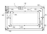
- the generated travel route includes a circuit travel route (see FIG. 5) set in the outer peripheral region and a reciprocating travel route (see FIG. 6) set in the inner region.
- the rice transplanter first performs seedling planting work (a type of automatic running work) on the inner area along the reciprocating running path (referred to as the internal working running mode), and then seedlings on the outer peripheral area along the orbiting running path. Perform planting work (referred to as lap work running mode).
- the orbital travel route consists of an orbital straight route that extends parallel to the field boundary (shore) and a direction change route that incorporates forward and backward movements to connect the orbital straight routes.
- the code R1 is assigned to the circular straight path
- the code R2 is assigned to the direction change path.
- the reciprocating travel path consists of a large number of straight paths that are substantially parallel to each other and a turning path (U-turn path) that connects the straight paths. In each straight route, planting of seedlings is started from the planting start position (which is also the turning end position), and planting of seedlings is finished at the planting end position (which is also the turning start position).
- planting start position which is also the turning end position
- planting of seedlings is finished at the planting end position (which is also the turning start position).
- a reference numeral US is assigned to the planting start position
- a reference numeral UF is assigned to the planting end position
- R3 is assigned to the straight path
- the reference numeral R5 is assigned to the turning path.
- reference numeral R4 is assigned to the transition route for transitioning from the reciprocating travel route to the orbital travel route.
- the transition path is similar to the turning path.
- the working width of the rice transplanter is indicated by the reference numeral W
- the entrance and exit of the rice transplanter to the field are drawn by diagonal lines
- the reference numeral GA is given.
- FIG. 6 shows a start guide route (reference numeral R6 is assigned in FIG.
- the rice transplanter first manually travels into the field through the doorway and stops at a predetermined position. After that, the rice transplanter automatically travels to the travel start position along the start guide route, which is the travel route to the travel start position, which is the start point of the seedling planting work.
- the traveling mode becomes the internal working traveling mode, and the vehicle automatically travels along the reciprocating traveling route shown in FIG. 6, and the seedling planting work in the internal area is performed.
- seedling replenishment process #G is performed.
- the traveling mode becomes the orbiting work traveling mode, and the outer peripheral planting processing # H, which is the seedling planting operation along the orbiting traveling path shown in FIG. 5, is executed.
- the orbital travel route includes an inner circumference travel route for the inner circumference that travels first, and an outer circumference travel route for the outer circumference that travels thereafter.
- the rice transplanter exits the field through the entrance / exit after the seedling planting work along the outer circumference traveling route. Seedling planting work along the inner circuit route is performed automatically. Since the seedling planting work along the outer peripheral traveling route requires precise traveling, manned automatic traveling in which the driver as a monitor is on board is preferable even in automatic traveling.
- FIG. 7 shows a control block diagram of the control system of this rice transplanter.
- the control system of the rice transplanter includes a control device 100 that controls various operations of the rice transplanter, a general-purpose terminal 9 that can exchange data with the control device 100, and a remote controller 90. Signals from the positioning unit 8, the operation mode switching operation tool 24, the traveling sensor group 28, the work sensor group 29, and the obstacle detector 80 are input to the control device 100. The control signal from the control device 100 is output to the traveling equipment group 1A and the working equipment group 1B.
- the traveling equipment group 1A includes, for example, a steering motor M1 and a speed change operation motor M2, and the steering angle is adjusted by controlling the steering motor M1 based on a control signal from the control device 100.
- the vehicle speed is adjusted by controlling the speed change operation motor M2.
- the elevating cylinder 11a for elevating and adjusting the seedling planting device 3 the seedling amount adjusting device for adjusting the seedling amount with the planting mechanism 32, and the fertilizer feeding amount with the feeding mechanism 42 are changed. Includes feeding amount adjustment equipment and the like.
- the travel sensor group 28 includes various sensors that detect states such as steering angle, vehicle speed, engine speed, and set values for them.
- the work sensor group 29 includes various sensors that detect the state of the link mechanism 11, the seedling planting device 3, and the fertilizer application device 4.
- the control device 100 includes a travel control unit 6, a work control unit 51, an airframe position calculation unit 52, a travel route management unit 53, an operation control state detection unit 55, a cross-border management unit 57, an input signal processing unit 50a, and a communication unit 50b. It is equipped.
- the input signal processing unit 50a processes signals from various sensors, switches, levers, etc. provided in the rice transplanter and transfers them to the functional unit built in the control device 100.
- the communication unit 50b has a wireless communication function, performs data communication with the outside, for example, data communication with the remote control 90, and the received data is transferred to the input signal processing unit 50a.
- the travel control unit 6 is provided with an automatic travel control unit 6A, a manual travel control unit 6B, and a control management unit 6C.
- the automatic driving control unit 6A performs speed control and steering control during automatic driving.
- the lateral deviation and the directional deviation are reduced based on the lateral deviation and the directional deviation calculated by comparing the target traveling route set by the traveling route management unit 53 with the aircraft position calculated by the aircraft position calculation unit 52. Steering control is performed so as to do so.
- this rice transplanter is equipped with a straight-line maintenance operation mode that automatically travels straight so as to maintain the direction of the reference line defined by at least two points. ing.
- the straight traveling route managed by the traveling route management unit 53 can be diverted.
- the manual driving control unit 6B controls the steering motor M1 based on the amount of operation of the steering wheel 21.
- the control management unit 6C selects one of the automatic traveling mode, the straight line maintenance operation mode, and the manual operation mode based on the signal from the operation mode switching operation tool 24.
- the work control unit 51 automatically controls the work equipment group 1B based on a program given in advance, and in manual driving, it controls the work equipment group 1B based on the operation of the driver.
- the aircraft position calculation unit 52 calculates the map coordinates (airframe position) of the aircraft 1 based on the satellite positioning data sequentially sent from the positioning unit 8.
- the general-purpose terminal 9 is provided with a field information storage unit 91, a field map creation unit 92, a travel route generation unit 93, a boundary line calculation unit 94, and a travel locus generation unit 95.
- the field information storage unit 91 stores information about the field such as planted seeds, the entrance (exit) position of the field, and the position where seedlings can be replenished.
- the field map creation unit 92 performs the map creation process described with reference to FIG.
- the travel route generation unit 93 divides the field into an internal region based on the field map created by the field map creation unit 92, and sets a circuit travel route for traveling in the outer peripheral region and a reciprocating travel route in the internal region. Generate.
- the boundary line calculation unit 94 performs the boundary line calculation process described with reference to FIG.
- the map creation process by the field map creation unit 92 and the boundary line calculation process by the boundary line calculation unit 94 require a travel locus in the map creation teaching run.
- the traveling locus generation unit 95 generates a traveling locus of the aircraft 1 based on the aircraft position calculated by the aircraft position calculation unit 52.
- the travel route management unit 53 receives and manages the travel route generated by the travel route generation unit 93 from the general-purpose terminal 9, and sequentially sets the travel route that is the target of the aircraft steering in the automatic travel mode.
- the operation control state detection unit 55 detects the travel control state and the work control state based on the control information handled by the control device 100.
- the cross-border management unit 57 has a function for preventing the aircraft 1 from coming into contact with a boundary object such as a ridge when the aircraft 1 exceeds the boundary line (boundary line data) calculated by the boundary line calculation unit 94. .. Therefore, the cross-border management unit 57 includes a boundary line storage unit 57a, a cross-border prevention control unit 57b, a turning locus estimation unit 57c, and a turning cross-border determination unit 57d.
- the boundary line storage unit 57a stores the boundary line received from the boundary line calculation unit 94.
- the cross-border prevention control unit 57b determines whether or not the aircraft 1 does not cross the boundary line based on the position of the aircraft, and gives a stop command to the travel control unit 6 for prohibiting the aircraft 1 from traveling beyond the boundary line.
- the cross-border prevention control unit 57b has a straight-ahead cross-border prevention mode for preventing cross-borders for the machine 1 traveling straight, and a turning cross-border prevention mode for preventing cross-borders for the machine 1 traveling in a turning manner.
- the cross-border prevention control unit 57b sets the aircraft 1 and the boundary line from the aircraft position given by the aircraft position calculation unit 52 and the boundary line facing the aircraft traveling direction read from the boundary line storage unit 57a. Calculate the separation distance between. When the calculated separation distance is within a predetermined distance, the cross-border prevention control unit 57b gives a stop command to the travel control unit 6.
- cross-border prevention control based on the calculation of the separation distance as in the straight-ahead cross-border prevention mode is not used, and cross-border crossing by the turning cross-border prevention mode is not used. Prevention control is performed.
- cross-border prevention control based on the estimated turning locus of the aircraft 1 is performed by using the turning locus estimation unit 57c and the turning cross-border determination unit 57d.
- the turning locus estimation unit 57c estimates the turning locus, which is the locus of the aircraft 1 during turning traveling.
- the turning boundary crossing determination unit 57d determines whether or not the aircraft crosses the boundary line in the actual turning running based on the estimated turning locus.
- cross-border prevention control routine by the cross-border management unit 57 will be described with reference to the flowchart of FIG.
- this routine first, it is checked whether or not the start of turning running is imminent from the set running route for automatic running (# 01). If the start of the turning run is not imminent, step # 01 is repeated.
- a preset cross-border prevention area in this embodiment, a cross-border prevention line and a ridge set on the inner region side of the cross-border line. It is checked whether or not it is in the area between the boundary object such as, or the outer peripheral area described above (# 02).
- the process returns to step # 01. If the aircraft 1 is within the cross-border prevention area (# 02 "inside” branch), the following pre-turning cross-border determination process is performed.
- the turning locus during turning is estimated by the turning locus estimation unit 57c from the position of the aircraft and the steering angle used for turning (# 11).
- the cross-border determination unit 57d at the time of turning determines whether or not the aircraft 1 crosses the boundary line in the actual turning running from now on based on the estimated turning locus (# 12). If the result of this cross-border determination is "non-cross-border" (# 12 "non-cross-border” branch), this turning run is permitted (# 21), and turning running is started (# 22).
- the cross-border prevention control unit 57b sets the first cross-border avoidance turning run to avoid cross-border (# 13), and this set cross-border crossing travel is set.
- the turning locus in the avoidance turning running is estimated by the turning locus estimation unit 57c (# 14). Based on the estimated turning locus, it is determined whether or not the aircraft 1 crosses the boundary line in this cross-border avoidance turning running (# 12). If the result of this cross-border determination is "non-cross-border” (# 12 "non-cross-border” branch), cross-border avoidance turning is permitted (# 21), and turning is started (# 22).
- cross-border avoidance running using reverse movement is a reliable cross-border avoidance, but time loss occurs.
- Cross-border avoidance running only forward is not a reliable cross-border avoidance, but time loss is small. Therefore, the first cross-border avoidance turning run uses the cross-border avoidance run only for forward movement, and the second cross-border avoidance turning run uses the cross-border avoidance running using the reverse movement.
- the actual cross-border determination for determining whether or not at least a part of the aircraft 1 is crossed at the current position is performed (# 31). If the result of the actual cross-border determination is "non-cross-border" (# 31 "non-cross-border” branch), the process returns to step # 23 and the turning run is continued. If the result of the actual cross-border determination is "cross-border” (# 12 "cross-border” branch), the cross-border prevention control unit 57b gives a stop command to the traveling control unit 6, and the aircraft 1 stops (# 33).
- the cross-border prevention control unit 57b sets a cross-border avoidance turning run (# 34) in which the cross-border avoidance turning control unit 57b leaves the cross-border line using reverse movement, and the turning locus in the set cross-border avoiding turning running is estimated by the turning locus estimation unit 57c. Will be (# 35). Based on the estimated turning locus, it is determined whether or not the aircraft 1 crosses the boundary line in this cross-border avoidance turning running (# 36). If the result of this cross-border determination is "non-cross-border" (# 36 "non-cross-border” branch), this cross-border avoidance turning run is permitted, turning running is resumed (# 37), and control returns to step # 23.
- cross-border If the result of the cross-border determination is "cross-border" (# 12 "cross-border” branch), a warning that the aircraft 1 cannot leave the border line by automatic driving is notified through the general-purpose terminal 9 (# 41). At the same time, the automatic operation is canceled (# 42), and this cross-border prevention routine ends. After that, the cross-border prevention control is turned off, and the aircraft 1 is separated from the boundary line by manual driving while carefully avoiding interference between the aircraft 1 and the boundary object.
- step # 02 if the state of the aircraft 1 is just before the start of turning and the aircraft 1 is in the cross-border prevention area, the aircraft 1 may be temporarily stopped before proceeding to the next step.
- the steering angle on the turning path by the automatic traveling control unit 6A may be controlled so as to follow the generated turning path, or the steering angle determined in advance so as to be a predetermined turning path. It may be performed by the control using.
- the rice transplanter is adopted as the agricultural work vehicle, but it may be an agricultural work vehicle such as a combine harvester, a tractor, a direct sowing machine, or a spraying (spraying) management machine.
- It may be configured as an automatic traveling control program that realizes the function of each member in the above embodiment on a computer. Further, it may be configured as a recording medium in which an automatic traveling control program that realizes the functions of each member in the above embodiment on a computer is recorded. Further, it may be configured as an automatic traveling control method in which what is performed by each member in the above embodiment is performed by one or a plurality of steps.
- the present invention is applicable to an agricultural work vehicle capable of autonomous driving.
- Aircraft 6 Travel control unit 8: Positioning unit 8A: Satellite positioning module 8B: Inertial measurement module 9: General-purpose terminal 52: Aircraft position calculation unit 53: Travel route management unit 55: Operation control state detection unit 57: Cross-border management unit 57a: Boundary line storage unit 57b: Cross-border prevention control unit 57c: Turning locus estimation unit 57d: Turn-time cross-border determination unit 94: Boundary line calculation unit 95: Travel locus generation unit 100: Control device
Landscapes
- Engineering & Computer Science (AREA)
- Life Sciences & Earth Sciences (AREA)
- Radar, Positioning & Navigation (AREA)
- Remote Sensing (AREA)
- Automation & Control Theory (AREA)
- General Physics & Mathematics (AREA)
- Physics & Mathematics (AREA)
- Aviation & Aerospace Engineering (AREA)
- Mechanical Engineering (AREA)
- Soil Sciences (AREA)
- Environmental Sciences (AREA)
- Guiding Agricultural Machines (AREA)
- Control Of Driving Devices And Active Controlling Of Vehicle (AREA)
- Catching Or Destruction (AREA)
Priority Applications (2)
| Application Number | Priority Date | Filing Date | Title |
|---|---|---|---|
| KR1020227018883A KR20220125221A (ko) | 2020-01-14 | 2020-05-19 | 농작업차, 자동 주행 제어 프로그램, 자동 주행 제어 프로그램을 기록한 기록 매체, 자동 주행 제어 방법 |
| CN202080085504.1A CN114786464A (zh) | 2020-01-14 | 2020-05-19 | 农业作业车、自动行驶控制程序、记录有自动行驶控制程序的记录介质、自动行驶控制方法 |
Applications Claiming Priority (2)
| Application Number | Priority Date | Filing Date | Title |
|---|---|---|---|
| JP2020003696A JP7343405B2 (ja) | 2020-01-14 | 2020-01-14 | 農作業車 |
| JP2020-003696 | 2020-01-14 |
Publications (1)
| Publication Number | Publication Date |
|---|---|
| WO2021145005A1 true WO2021145005A1 (ja) | 2021-07-22 |
Family
ID=76864254
Family Applications (1)
| Application Number | Title | Priority Date | Filing Date |
|---|---|---|---|
| PCT/JP2020/019722 Ceased WO2021145005A1 (ja) | 2020-01-14 | 2020-05-19 | 農作業車、自動走行制御プログラム、自動走行制御プログラムを記録した記録媒体、自動走行制御方法 |
Country Status (4)
| Country | Link |
|---|---|
| JP (3) | JP7343405B2 (https=) |
| KR (1) | KR20220125221A (https=) |
| CN (1) | CN114786464A (https=) |
| WO (1) | WO2021145005A1 (https=) |
Cited By (1)
| Publication number | Priority date | Publication date | Assignee | Title |
|---|---|---|---|---|
| CN117016069A (zh) * | 2023-08-15 | 2023-11-10 | 湖南农业大学 | 一种用于旋耕机的左右距离自动可调的平地器及其调整方法 |
Families Citing this family (4)
| Publication number | Priority date | Publication date | Assignee | Title |
|---|---|---|---|---|
| JP7343405B2 (ja) * | 2020-01-14 | 2023-09-12 | 株式会社クボタ | 農作業車 |
| KR102673875B1 (ko) * | 2021-08-27 | 2024-06-11 | 주식회사 알티케이 | 작업 차량의 작업 경로 자동 생성 방법 및 시스템 |
| JP7769589B2 (ja) * | 2022-06-15 | 2025-11-13 | ヤンマーホールディングス株式会社 | 自動走行方法、自動走行システム、及び自動走行プログラム |
| JP7813204B2 (ja) * | 2022-08-18 | 2026-02-12 | ヤンマーホールディングス株式会社 | 経路設定方法、経路設定システム、及び経路設定プログラム |
Citations (5)
| Publication number | Priority date | Publication date | Assignee | Title |
|---|---|---|---|---|
| JP2002182746A (ja) * | 2000-12-19 | 2002-06-26 | Yanmar Agricult Equip Co Ltd | 農業用作業車 |
| JP3656332B2 (ja) * | 1996-08-28 | 2005-06-08 | 独立行政法人農業・生物系特定産業技術研究機構 | 作業車両の無人走行による無人作業方法 |
| JP2019165665A (ja) * | 2018-03-23 | 2019-10-03 | ヤンマー株式会社 | 作業車両用の自動走行システム |
| JP2019168812A (ja) * | 2018-03-22 | 2019-10-03 | ヤンマー株式会社 | 自動走行システム |
| JP2020099240A (ja) * | 2018-12-21 | 2020-07-02 | 株式会社クボタ | 圃場作業車及び圃場地図データ生成システム |
Family Cites Families (9)
| Publication number | Priority date | Publication date | Assignee | Title |
|---|---|---|---|---|
| KR102228386B1 (ko) * | 2015-08-12 | 2021-03-16 | 현대자동차주식회사 | 선회 궤적 예측 기반의 충돌 회피 제동 제어 방법 및 장치 |
| DE102016222782A1 (de) * | 2016-11-18 | 2018-05-24 | Audi Ag | Autonomes Steuern eines Kraftfahrzeugs anhand von Spurdaten; Kraftfahrzeug |
| JP2018117559A (ja) | 2017-01-24 | 2018-08-02 | 株式会社クボタ | 作業車 |
| JP6766006B2 (ja) * | 2017-04-26 | 2020-10-07 | 株式会社クボタ | 自動操舵システム |
| CN107817794B (zh) * | 2017-10-13 | 2021-07-23 | 上海司南卫星导航技术股份有限公司 | 自动导航方法、控制装置及导航系统 |
| JP2019080496A (ja) * | 2017-10-27 | 2019-05-30 | 井関農機株式会社 | コンバインの操縦アシスト装置 |
| JP7174484B2 (ja) * | 2017-12-18 | 2022-11-17 | 株式会社クボタ | 農作業車 |
| CN110654460B (zh) * | 2019-12-02 | 2020-03-24 | 浙江中车电车有限公司 | 一种用于车辆转弯主动控制的方法 |
| JP7343405B2 (ja) * | 2020-01-14 | 2023-09-12 | 株式会社クボタ | 農作業車 |
-
2020
- 2020-01-14 JP JP2020003696A patent/JP7343405B2/ja active Active
- 2020-05-19 CN CN202080085504.1A patent/CN114786464A/zh active Pending
- 2020-05-19 WO PCT/JP2020/019722 patent/WO2021145005A1/ja not_active Ceased
- 2020-05-19 KR KR1020227018883A patent/KR20220125221A/ko not_active Ceased
-
2023
- 2023-08-30 JP JP2023140166A patent/JP7678042B2/ja active Active
-
2025
- 2025-04-30 JP JP2025075552A patent/JP2025107313A/ja active Pending
Patent Citations (5)
| Publication number | Priority date | Publication date | Assignee | Title |
|---|---|---|---|---|
| JP3656332B2 (ja) * | 1996-08-28 | 2005-06-08 | 独立行政法人農業・生物系特定産業技術研究機構 | 作業車両の無人走行による無人作業方法 |
| JP2002182746A (ja) * | 2000-12-19 | 2002-06-26 | Yanmar Agricult Equip Co Ltd | 農業用作業車 |
| JP2019168812A (ja) * | 2018-03-22 | 2019-10-03 | ヤンマー株式会社 | 自動走行システム |
| JP2019165665A (ja) * | 2018-03-23 | 2019-10-03 | ヤンマー株式会社 | 作業車両用の自動走行システム |
| JP2020099240A (ja) * | 2018-12-21 | 2020-07-02 | 株式会社クボタ | 圃場作業車及び圃場地図データ生成システム |
Cited By (1)
| Publication number | Priority date | Publication date | Assignee | Title |
|---|---|---|---|---|
| CN117016069A (zh) * | 2023-08-15 | 2023-11-10 | 湖南农业大学 | 一种用于旋耕机的左右距离自动可调的平地器及其调整方法 |
Also Published As
| Publication number | Publication date |
|---|---|
| KR20220125221A (ko) | 2022-09-14 |
| JP2023155424A (ja) | 2023-10-20 |
| JP7678042B2 (ja) | 2025-05-15 |
| JP7343405B2 (ja) | 2023-09-12 |
| JP2021108598A (ja) | 2021-08-02 |
| JP2025107313A (ja) | 2025-07-17 |
| CN114786464A (zh) | 2022-07-22 |
Similar Documents
| Publication | Publication Date | Title |
|---|---|---|
| WO2021145005A1 (ja) | 農作業車、自動走行制御プログラム、自動走行制御プログラムを記録した記録媒体、自動走行制御方法 | |
| US9526199B2 (en) | Work vehicle coordinating system | |
| JP2025107313A5 (https=) | ||
| JP7091189B2 (ja) | 作業車両用の自動走行システム | |
| JP7042732B2 (ja) | 自動操舵システムおよび自動操舵方法 | |
| JP2021108597A (ja) | 自動走行可能な農作業車 | |
| JP7191004B2 (ja) | 作業機 | |
| WO2021145046A1 (ja) | 農作業車 | |
| JP7664996B2 (ja) | 農作業車 | |
| JP6991058B2 (ja) | 自動操舵システム | |
| JP2024174038A (ja) | 自動走行制御システム | |
| JP7520171B2 (ja) | 農作業機 | |
| JP7515260B2 (ja) | 農作業車 | |
| JP2021108600A (ja) | 農作業車 | |
| WO2023112610A1 (ja) | 圃場作業車 | |
| JP2022118848A (ja) | 作業車両 | |
| JP7660492B2 (ja) | 自動操舵システム | |
| KR102957667B1 (ko) | 농작업차, 자동 주행 제어 프로그램, 자동 주행 제어 프로그램을 기록한 기록 매체, 자동 주행 제어 방법 | |
| JP7471261B2 (ja) | 作業車および自動走行制御システム | |
| JP7695184B2 (ja) | 自動走行制御システム | |
| JP2019022524A (ja) | 作業機 | |
| JP2025103723A (ja) | 圃場作業車 | |
| JP2022101926A (ja) | 作業車両 | |
| JP2023090398A (ja) | 自動走行水田作業車 |
Legal Events
| Date | Code | Title | Description |
|---|---|---|---|
| 121 | Ep: the epo has been informed by wipo that ep was designated in this application |
Ref document number: 20914137 Country of ref document: EP Kind code of ref document: A1 |
|
| NENP | Non-entry into the national phase |
Ref country code: DE |
|
| 122 | Ep: pct application non-entry in european phase |
Ref document number: 20914137 Country of ref document: EP Kind code of ref document: A1 |
|
| WWG | Wipo information: grant in national office |
Ref document number: 202217032584 Country of ref document: IN |