WO2021137284A1 - 動力伝達装置 - Google Patents
動力伝達装置 Download PDFInfo
- Publication number
- WO2021137284A1 WO2021137284A1 PCT/JP2020/045426 JP2020045426W WO2021137284A1 WO 2021137284 A1 WO2021137284 A1 WO 2021137284A1 JP 2020045426 W JP2020045426 W JP 2020045426W WO 2021137284 A1 WO2021137284 A1 WO 2021137284A1
- Authority
- WO
- WIPO (PCT)
- Prior art keywords
- oil
- gear
- box
- wall portion
- rotation axis
- Prior art date
Links
- 230000005540 biological transmission Effects 0.000 title claims abstract description 58
- 239000010687 lubricating oil Substances 0.000 claims description 7
- 238000011144 upstream manufacturing Methods 0.000 claims description 3
- 238000003756 stirring Methods 0.000 abstract description 7
- 239000003921 oil Substances 0.000 description 222
- 230000002093 peripheral effect Effects 0.000 description 93
- 238000003780 insertion Methods 0.000 description 9
- 230000037431 insertion Effects 0.000 description 9
- 229910000976 Electrical steel Inorganic materials 0.000 description 5
- 230000000149 penetrating effect Effects 0.000 description 5
- 238000010586 diagram Methods 0.000 description 3
- 230000012447 hatching Effects 0.000 description 3
- 238000009434 installation Methods 0.000 description 2
- 238000010030 laminating Methods 0.000 description 2
- 238000004804 winding Methods 0.000 description 2
- 229910000831 Steel Inorganic materials 0.000 description 1
- 238000013459 approach Methods 0.000 description 1
- 238000001816 cooling Methods 0.000 description 1
- 239000000498 cooling water Substances 0.000 description 1
- 239000013256 coordination polymer Substances 0.000 description 1
- 230000001050 lubricating effect Effects 0.000 description 1
- 230000010363 phase shift Effects 0.000 description 1
- 125000006850 spacer group Chemical group 0.000 description 1
- 239000010959 steel Substances 0.000 description 1
Images


Classifications
-
- F—MECHANICAL ENGINEERING; LIGHTING; HEATING; WEAPONS; BLASTING
- F16—ENGINEERING ELEMENTS AND UNITS; GENERAL MEASURES FOR PRODUCING AND MAINTAINING EFFECTIVE FUNCTIONING OF MACHINES OR INSTALLATIONS; THERMAL INSULATION IN GENERAL
- F16H—GEARING
- F16H57/00—General details of gearing
- F16H57/04—Features relating to lubrication or cooling or heating
- F16H57/0409—Features relating to lubrication or cooling or heating characterised by the problem to increase efficiency, e.g. by reducing splash losses
-
- F—MECHANICAL ENGINEERING; LIGHTING; HEATING; WEAPONS; BLASTING
- F16—ENGINEERING ELEMENTS AND UNITS; GENERAL MEASURES FOR PRODUCING AND MAINTAINING EFFECTIVE FUNCTIONING OF MACHINES OR INSTALLATIONS; THERMAL INSULATION IN GENERAL
- F16H—GEARING
- F16H57/00—General details of gearing
- F16H57/04—Features relating to lubrication or cooling or heating
- F16H57/042—Guidance of lubricant
- F16H57/0427—Guidance of lubricant on rotary parts, e.g. using baffles for collecting lubricant by centrifugal force
-
- B—PERFORMING OPERATIONS; TRANSPORTING
- B60—VEHICLES IN GENERAL
- B60K—ARRANGEMENT OR MOUNTING OF PROPULSION UNITS OR OF TRANSMISSIONS IN VEHICLES; ARRANGEMENT OR MOUNTING OF PLURAL DIVERSE PRIME-MOVERS IN VEHICLES; AUXILIARY DRIVES FOR VEHICLES; INSTRUMENTATION OR DASHBOARDS FOR VEHICLES; ARRANGEMENTS IN CONNECTION WITH COOLING, AIR INTAKE, GAS EXHAUST OR FUEL SUPPLY OF PROPULSION UNITS IN VEHICLES
- B60K1/00—Arrangement or mounting of electrical propulsion units
-
- F—MECHANICAL ENGINEERING; LIGHTING; HEATING; WEAPONS; BLASTING
- F16—ENGINEERING ELEMENTS AND UNITS; GENERAL MEASURES FOR PRODUCING AND MAINTAINING EFFECTIVE FUNCTIONING OF MACHINES OR INSTALLATIONS; THERMAL INSULATION IN GENERAL
- F16H—GEARING
- F16H37/00—Combinations of mechanical gearings, not provided for in groups F16H1/00 - F16H35/00
- F16H37/02—Combinations of mechanical gearings, not provided for in groups F16H1/00 - F16H35/00 comprising essentially only toothed or friction gearings
- F16H37/06—Combinations of mechanical gearings, not provided for in groups F16H1/00 - F16H35/00 comprising essentially only toothed or friction gearings with a plurality of driving or driven shafts; with arrangements for dividing torque between two or more intermediate shafts
- F16H37/08—Combinations of mechanical gearings, not provided for in groups F16H1/00 - F16H35/00 comprising essentially only toothed or friction gearings with a plurality of driving or driven shafts; with arrangements for dividing torque between two or more intermediate shafts with differential gearing
- F16H37/0806—Combinations of mechanical gearings, not provided for in groups F16H1/00 - F16H35/00 comprising essentially only toothed or friction gearings with a plurality of driving or driven shafts; with arrangements for dividing torque between two or more intermediate shafts with differential gearing with a plurality of driving or driven shafts
- F16H37/0813—Combinations of mechanical gearings, not provided for in groups F16H1/00 - F16H35/00 comprising essentially only toothed or friction gearings with a plurality of driving or driven shafts; with arrangements for dividing torque between two or more intermediate shafts with differential gearing with a plurality of driving or driven shafts with only one input shaft
- F16H37/082—Combinations of mechanical gearings, not provided for in groups F16H1/00 - F16H35/00 comprising essentially only toothed or friction gearings with a plurality of driving or driven shafts; with arrangements for dividing torque between two or more intermediate shafts with differential gearing with a plurality of driving or driven shafts with only one input shaft and additional planetary reduction gears
-
- F—MECHANICAL ENGINEERING; LIGHTING; HEATING; WEAPONS; BLASTING
- F16—ENGINEERING ELEMENTS AND UNITS; GENERAL MEASURES FOR PRODUCING AND MAINTAINING EFFECTIVE FUNCTIONING OF MACHINES OR INSTALLATIONS; THERMAL INSULATION IN GENERAL
- F16H—GEARING
- F16H57/00—General details of gearing
- F16H57/02—Gearboxes; Mounting gearing therein
- F16H57/037—Gearboxes for accommodating differential gearings
-
- F—MECHANICAL ENGINEERING; LIGHTING; HEATING; WEAPONS; BLASTING
- F16—ENGINEERING ELEMENTS AND UNITS; GENERAL MEASURES FOR PRODUCING AND MAINTAINING EFFECTIVE FUNCTIONING OF MACHINES OR INSTALLATIONS; THERMAL INSULATION IN GENERAL
- F16H—GEARING
- F16H57/00—General details of gearing
- F16H57/04—Features relating to lubrication or cooling or heating
- F16H57/0457—Splash lubrication
-
- F—MECHANICAL ENGINEERING; LIGHTING; HEATING; WEAPONS; BLASTING
- F16—ENGINEERING ELEMENTS AND UNITS; GENERAL MEASURES FOR PRODUCING AND MAINTAINING EFFECTIVE FUNCTIONING OF MACHINES OR INSTALLATIONS; THERMAL INSULATION IN GENERAL
- F16H—GEARING
- F16H57/00—General details of gearing
- F16H57/04—Features relating to lubrication or cooling or heating
- F16H57/048—Type of gearings to be lubricated, cooled or heated
- F16H57/0482—Gearings with gears having orbital motion
- F16H57/0486—Gearings with gears having orbital motion with fixed gear ratio
-
- B—PERFORMING OPERATIONS; TRANSPORTING
- B60—VEHICLES IN GENERAL
- B60K—ARRANGEMENT OR MOUNTING OF PROPULSION UNITS OR OF TRANSMISSIONS IN VEHICLES; ARRANGEMENT OR MOUNTING OF PLURAL DIVERSE PRIME-MOVERS IN VEHICLES; AUXILIARY DRIVES FOR VEHICLES; INSTRUMENTATION OR DASHBOARDS FOR VEHICLES; ARRANGEMENTS IN CONNECTION WITH COOLING, AIR INTAKE, GAS EXHAUST OR FUEL SUPPLY OF PROPULSION UNITS IN VEHICLES
- B60K1/00—Arrangement or mounting of electrical propulsion units
- B60K2001/001—Arrangement or mounting of electrical propulsion units one motor mounted on a propulsion axle for rotating right and left wheels of this axle
-
- B—PERFORMING OPERATIONS; TRANSPORTING
- B60—VEHICLES IN GENERAL
- B60Y—INDEXING SCHEME RELATING TO ASPECTS CROSS-CUTTING VEHICLE TECHNOLOGY
- B60Y2200/00—Type of vehicle
- B60Y2200/90—Vehicles comprising electric prime movers
- B60Y2200/91—Electric vehicles
-
- F—MECHANICAL ENGINEERING; LIGHTING; HEATING; WEAPONS; BLASTING
- F16—ENGINEERING ELEMENTS AND UNITS; GENERAL MEASURES FOR PRODUCING AND MAINTAINING EFFECTIVE FUNCTIONING OF MACHINES OR INSTALLATIONS; THERMAL INSULATION IN GENERAL
- F16H—GEARING
- F16H57/00—General details of gearing
- F16H57/02—Gearboxes; Mounting gearing therein
- F16H57/021—Shaft support structures, e.g. partition walls, bearing eyes, casing walls or covers with bearings
- F16H2057/0216—Intermediate shaft supports, e.g. by using a partition wall
-
- F—MECHANICAL ENGINEERING; LIGHTING; HEATING; WEAPONS; BLASTING
- F16—ENGINEERING ELEMENTS AND UNITS; GENERAL MEASURES FOR PRODUCING AND MAINTAINING EFFECTIVE FUNCTIONING OF MACHINES OR INSTALLATIONS; THERMAL INSULATION IN GENERAL
- F16H—GEARING
- F16H48/00—Differential gearings
- F16H48/06—Differential gearings with gears having orbital motion
- F16H48/08—Differential gearings with gears having orbital motion comprising bevel gears
-
- F—MECHANICAL ENGINEERING; LIGHTING; HEATING; WEAPONS; BLASTING
- F16—ENGINEERING ELEMENTS AND UNITS; GENERAL MEASURES FOR PRODUCING AND MAINTAINING EFFECTIVE FUNCTIONING OF MACHINES OR INSTALLATIONS; THERMAL INSULATION IN GENERAL
- F16H—GEARING
- F16H57/00—General details of gearing
- F16H57/02—Gearboxes; Mounting gearing therein
- F16H57/027—Gearboxes; Mounting gearing therein characterised by means for venting gearboxes, e.g. air breathers
-
- F—MECHANICAL ENGINEERING; LIGHTING; HEATING; WEAPONS; BLASTING
- F16—ENGINEERING ELEMENTS AND UNITS; GENERAL MEASURES FOR PRODUCING AND MAINTAINING EFFECTIVE FUNCTIONING OF MACHINES OR INSTALLATIONS; THERMAL INSULATION IN GENERAL
- F16H—GEARING
- F16H57/00—General details of gearing
- F16H57/04—Features relating to lubrication or cooling or heating
- F16H57/042—Guidance of lubricant
- F16H57/0421—Guidance of lubricant on or within the casing, e.g. shields or baffles for collecting lubricant, tubes, pipes, grooves, channels or the like
- F16H57/0423—Lubricant guiding means mounted or supported on the casing, e.g. shields or baffles for collecting lubricant, tubes or pipes
-
- F—MECHANICAL ENGINEERING; LIGHTING; HEATING; WEAPONS; BLASTING
- F16—ENGINEERING ELEMENTS AND UNITS; GENERAL MEASURES FOR PRODUCING AND MAINTAINING EFFECTIVE FUNCTIONING OF MACHINES OR INSTALLATIONS; THERMAL INSULATION IN GENERAL
- F16H—GEARING
- F16H57/00—General details of gearing
- F16H57/04—Features relating to lubrication or cooling or heating
- F16H57/0467—Elements of gearings to be lubricated, cooled or heated
- F16H57/0479—Gears or bearings on planet carriers
-
- F—MECHANICAL ENGINEERING; LIGHTING; HEATING; WEAPONS; BLASTING
- F16—ENGINEERING ELEMENTS AND UNITS; GENERAL MEASURES FOR PRODUCING AND MAINTAINING EFFECTIVE FUNCTIONING OF MACHINES OR INSTALLATIONS; THERMAL INSULATION IN GENERAL
- F16H—GEARING
- F16H57/00—General details of gearing
- F16H57/04—Features relating to lubrication or cooling or heating
- F16H57/048—Type of gearings to be lubricated, cooled or heated
- F16H57/0482—Gearings with gears having orbital motion
- F16H57/0483—Axle or inter-axle differentials
Definitions
- the present invention relates to a power transmission device.
- Patent Document 1 discloses a power transmission device for an electric vehicle having a bevel gear type differential mechanism and a planetary gear mechanism.
- This planetary gear mechanism comprises a stepped pinion gear having a large pinion gear and a small pinion gear.
- the power transmission device in a certain aspect of the present invention is A pinion gear with a large pinion gear and a small pinion gear, A wall portion that overlaps the orbit of the large pinion gear in the axial direction, A plate provided between the wall portion and the large pinion gear, It has a bottom provided through a clearance at the bottom of the plate and the orbit of the large pinion gear.
- stirring resistance can be reduced.
- FIG. 1 is a skeleton diagram illustrating a power transmission device 1 according to the present embodiment.
- FIG. 2 is a schematic cross-sectional view illustrating the power transmission device 1 according to the present embodiment.
- FIG. 3 is an enlarged view around the planetary reduction gear 4 of the power transmission device 1.
- FIG. 4 is an enlarged view of the power transmission device 1 around the differential mechanism 5.
- the power transmission device 1 includes a motor 2 and a planetary reduction gear 4 (reduction mechanism) that decelerates the output rotation of the motor 2 and inputs it to the differential mechanism 5.
- the power transmission device 1 also has a drive shaft 9 (9A, 9B) as a drive shaft and a park lock mechanism 3.
- a park lock mechanism 3, a planetary reduction gear 4, a differential mechanism 5, and a drive shaft 9 (9A, 9B) are provided along the transmission path of the output rotation of the motor 2. There is.
- the power transmission device 1 After the output rotation of the motor 2 is decelerated by the planetary reduction gear 4 and input to the differential mechanism 5, the power transmission device 1 is mounted via the drive shafts 9 (9A, 9B). It is transmitted to the left and right drive wheels W and W of the vehicle.
- the planetary reduction gear 4 is connected to the downstream side of the motor 2.
- the differential mechanism 5 is connected downstream of the planetary reduction gear 4.
- the drive shafts 9 (9A, 9B) are connected downstream of the differential mechanism 5.
- the main body box 10 of the power transmission device 1 has a first box 11 that houses the motor 2 and a second box 12 that is externally inserted into the first box 11.
- the main body box 10 has a third box 13 assembled to the first box 11 and a fourth box 14 assembled to the second box 12.
- the first box 11 has a cylindrical support wall portion 111 and a flange-shaped joint portion 112 provided at one end 111a of the support wall portion 111.
- the first box 11 is provided with the support wall portion 111 oriented along the rotation axis X of the motor 2.
- the motor 2 is housed inside the support wall portion 111.
- the joint portion 112 is provided in a direction orthogonal to the rotation axis X.
- the joint portion 112 is formed with an outer diameter larger than that of the support wall portion 111.
- the second box 12 includes a cylindrical peripheral wall portion 121, a flange-shaped joint portion 122 provided at one end 121a of the peripheral wall portion 121, and a flange-shaped joint portion 123 provided at the other end 121b of the peripheral wall portion 121. ,have.
- the peripheral wall portion 121 is formed with an inner diameter that can be extrapolated to the support wall portion 111 of the first box 11.
- the first box 11 and the second box 12 are assembled to each other by externally inserting the peripheral wall portion 121 of the second box 12 into the support wall portion 111 of the first box 11.
- the joint portion 122 on the one end 121a side of the peripheral wall portion 121 is in contact with the joint portion 112 of the first box 11 from the rotation axis X direction. These joints 122 and 112 are connected to each other by bolts (not shown).
- a plurality of concave grooves 111b are provided on the outer periphery of the support wall portion 111.
- the plurality of concave grooves 111b are provided at intervals in the rotation axis X direction.
- Each of the concave grooves 111b is provided over the entire circumference in the circumferential direction around the rotation axis X.
- the peripheral wall portion 121 of the second box 12 is externally inserted into the support wall portion 111 of the first box 11.
- the opening of the concave groove 111b is closed by the peripheral wall portion 121.
- a plurality of cooling passages CP through which cooling water flows are formed between the support wall portion 111 and the peripheral wall portion 121.
- ring grooves 111c and 111c are formed on both sides of the region where the concave groove 111b is provided.
- Seal rings 113 and 113 are fitted and attached to the ring grooves 111c and 111c. These seal rings 113 are pressed against the inner circumference of the peripheral wall portion 121 extrapolated to the support wall portion 111 to seal the gap between the outer circumference of the support wall portion 111 and the inner circumference of the peripheral wall portion 121.
- the other end 121b of the second box 12 is provided with a wall portion 120 extending toward the inner diameter side.
- the wall portion 120 is provided in a direction orthogonal to the rotation axis X.
- An opening 120a through which the drive shaft 9A is inserted is provided in a region of the wall portion 120 that intersects with the rotation axis X.
- a tubular motor support portion 125 surrounding the opening 120a is provided on the surface on the motor 2 side (right side in the drawing).
- the motor support portion 125 is inserted inside the coil end 253b described later.
- the motor support portion 125 faces the end portion 21b of the rotor core 21 with a gap in the rotation axis X direction.
- the peripheral wall portion 121 of the second box 12 has a thicker radial thickness in the lower region than in the upper region in the vertical direction with respect to the mounted state of the power transmission device 1 in the vehicle.
- An oil reservoir 128 is provided so as to penetrate in the rotation axis X direction in the thick region in the radial direction.
- the oil reservoir 128 communicates with the axial oil passage 138 provided at the joint 132 of the third box 13 via the communication hole 112a.
- the communication hole 112a is provided in the joint portion 112 of the first box 11.
- the third box 13 has a wall portion 130 orthogonal to the rotation axis X.
- a ring-shaped joint 132 is provided on the outer periphery of the wall 130 when viewed from the rotation axis X direction.
- the third box 13 is located on the opposite side (right side in the drawing) of the differential mechanism 5 when viewed from the first box 11.
- the joint portion 132 of the third box 13 is joined to the joint portion 112 of the first box 11 from the rotation axis X direction.
- the third box 13 and the first box 11 are connected to each other by bolts (not shown). In this state, in the first box 11, the opening of the support wall portion 111 on the joint portion 122 side (right side in the drawing) is closed by the third box 13.
- an insertion hole 130a for the drive shaft 9A is provided in the central portion of the wall portion 130.
- a lip seal RS is provided on the inner circumference of the insertion hole 130a.
- a lip portion (not shown) is elastically brought into contact with the outer circumference of the drive shaft 9A.
- the gap between the inner circumference of the insertion hole 130a and the outer circumference of the drive shaft 9A is sealed by the lip seal RS.
- a peripheral wall portion 131 surrounding the insertion hole 130a is provided on the surface of the wall portion 130 on the side of the first box 11 (left side in the drawing).
- a drive shaft 9A is supported on the inner circumference of the peripheral wall portion 131 via a bearing B4.
- a motor support portion 135 is provided on the motor 2 side (left side in the drawing) when viewed from the peripheral wall portion 131.
- the motor support portion 135 has a tubular shape that surrounds the outer circumference of the rotating shaft X at intervals.
- a cylindrical connecting wall 136 is connected to the outer circumference of the motor support portion 135.
- the connecting wall 136 is formed with an outer diameter larger than that of the peripheral wall portion 131 on the wall portion 130 side (right side in the drawing).
- the connection wall 136 is provided in a direction along the rotation axis X, and extends in a direction away from the motor 2.
- the connection wall 136 connects the motor support portion 135 and the wall portion 130 of the third box 13.
- the motor support portion 135 is supported by the third box 13 via the connecting wall 136.
- One end 20a side of the motor shaft 20 penetrates the inside of the motor support portion 135 from the motor 2 side to the peripheral wall portion 131 side.
- a bearing B1 is supported on the inner circumference of the motor support portion 135.
- the outer circumference of the motor shaft 20 is supported by the motor support portion 135 via the bearing B1.
- a lip seal RS is provided at a position adjacent to the bearing B1.
- an oil hole 136a which will be described later, is opened on the inner circumference of the connecting wall 136.
- the oil OL flows into the space (internal space Sc) surrounded by the connecting wall 136 from the oil hole 136a.
- the lip seal RS is provided to prevent the oil OL in the connecting wall 136 from flowing into the motor 2 side.
- the fourth box 14 has a peripheral wall portion 141 surrounding the outer periphery of the planetary reduction gear 4 and the differential mechanism 5, and a flange-shaped joint portion 142 provided at the end portion of the peripheral wall portion 141 on the second box 12 side. doing.
- the fourth box 14 is located on the differential mechanism 5 side (left side in the drawing) when viewed from the second box 12.
- the joint portion 142 of the fourth box 14 is joined to the joint portion 123 of the second box 12 from the rotation axis X direction.
- the fourth box 14 and the second box 12 are connected to each other by bolts (not shown).
- a motor chamber Sa accommodating the motor 2 and a gear chamber Sb accommodating the planetary reduction gear 4 and the differential mechanism 5 are formed inside the main body box 10 of the power transmission device 1.
- the motor chamber Sa is formed inside the first box 11 between the wall portion 120 of the second box 12 and the wall portion 130 of the third box 13.
- the gear chamber Sb is formed on the inner diameter side of the fourth box 14 between the wall portion 120 of the second box 12 and the peripheral wall portion 141 of the fourth box 14.
- a plate member 8 is provided inside the gear chamber Sb.
- the plate member 8 is fixed to the fourth box 14 with bolts B.
- the plate member 8 divides the gear chamber Sb into a first gear chamber Sb1 accommodating the planetary reduction gear 4 and the differential mechanism 5 and a second gear chamber Sb2 accommodating the park lock mechanism 3.
- the second gear chamber Sb2 is located between the first gear chamber Sb1 and the motor chamber Sa in the X direction of the rotation axis.
- the motor 2 has a cylindrical motor shaft 20, a cylindrical rotor core 21 extrapolated to the motor shaft 20, and a stator core 25 that surrounds the outer circumference of the rotor core 21 at intervals.
- bearings B1 and B1 are extrapolated and fixed on both sides of the rotor core 21.
- the bearing B1 located on one end 20a side (right side in the drawing) of the motor shaft 20 as viewed from the rotor core 21 is supported on the inner circumference of the motor support portion 135 of the third box 13.
- the bearing B1 located on the other end 20b side is supported on the inner circumference of the cylindrical motor support portion 125 of the second box 12.
- the motor support portions 135 and 125 are arranged on the inner diameter side of the coil ends 253a and 253b, which will be described later, with one end 21a and the other end 21b of the rotor core 21 facing each other with a gap in the rotation axis X direction. ing.
- the rotor core 21 is formed by laminating a plurality of silicon steel plates. Each of the silicon steel plates is extrapolated to the motor shaft 20 in a state where the relative rotation with the motor shaft 20 is restricted.
- the silicon steel plate has a ring shape when viewed from the rotation axis X direction of the motor shaft 20. On the outer peripheral side of the silicon steel plate, magnets of N pole and S pole (not shown) are alternately provided in the circumferential direction around the rotation axis X.
- the stator core 25 that surrounds the outer circumference of the rotor core 21 is formed by laminating a plurality of electromagnetic steel sheets.
- the stator core 25 is fixed to the inner circumference of the cylindrical support wall portion 111 of the first box 11.
- Each of the electrical steel sheets has a ring-shaped yoke portion 251 fixed to the inner circumference of the support wall portion 111, and a teeth portion 252 protruding from the inner circumference of the yoke portion 251 toward the rotor core 21.
- the stator core 25 having a configuration in which the winding 253 is distributed and wound across a plurality of teeth portions 252 is adopted.
- the stator core 25 is longer in the rotation axis X direction than the rotor core 21 by the amount of the coil ends 253a and 253b protruding in the rotation axis X direction.
- stator core having a configuration in which windings are centrally wound may be adopted for each of the plurality of tooth portions 252 protruding toward the rotor core 21 side.
- the wall portion 120 (motor support portion 125) of the second box 12 is provided with an opening 120a.
- the other end 20b side of the motor shaft 20 penetrates the opening 120a to the differential mechanism 5 side (left side in the drawing) and is located in the fourth box 14.
- the other end 20b of the motor shaft 20 faces the side gear 54A, which will be described later, with a gap in the rotation axis X direction inside the fourth box 14.
- a step portion 201 is provided in a region located in the fourth box 14.
- the step portion 201 is located in the vicinity of the motor support portion 125.
- a lip seal RS supported on the inner circumference of the motor support portion 125 is in contact with the outer periphery of the region between the step portion 201 and the bearing B1.
- the lip seal RS separates the motor chamber Sa accommodating the motor 2 and the gear chamber Sb in the fourth box 14.
- An oil OL for lubricating the planetary reduction gear 4 and the differential mechanism 5 is sealed in the inner diameter side of the fourth box 14 (see FIG. 2).
- the lip seal RS is provided to prevent the inflow of oil OL into the motor chamber Sa.
- the region from the step portion 201 to the vicinity of the other end 20b is a fitting portion 202 provided with a spline on the outer periphery.
- a park gear 30 and a sun gear 41 are spline-fitted on the outer circumference of the fitting portion 202.
- one side surface of the park gear 30 in the X direction of the rotation axis is in contact with the step portion 201 (right side in the drawing).
- One end 410a of the cylindrical base 410 of the sun gear 41 is in contact with the other side surface of the park gear 30 (left side in the figure).
- a nut N screwed into the other end 20b of the motor shaft 20 is in pressure contact with the other end 410b of the base portion 410 from the rotation axis X direction.
- the sun gear 41 and the park gear 30 are provided so as not to rotate relative to the motor shaft 20 in a state of being sandwiched between the nut N and the step portion 201.
- the sun gear 41 is provided in a positional relationship that overlaps with the motor 2 described above when viewed from the rotation axis X direction.
- the sun gear 41 has a tooth portion 411 on the outer periphery of the motor shaft 20 on the other end 20b side.
- a large pinion gear 431 of the stepped pinion gear 43 meshes with the outer periphery of the tooth portion 411.
- the stepped pinion gear 43 has a large pinion gear 431 that meshes with the sun gear 41 and a small pinion gear 432 having a diameter smaller than that of the large pinion gear 431.
- the stepped pinion gear 43 is a gear component in which a large pinion gear 431 and a small pinion gear 432 are integrally provided side by side in the direction of the axis X1 parallel to the rotation axis X.
- the large pinion gear 431 is formed with an outer diameter R1 larger than the outer diameter R2 of the small pinion gear 432.
- the stepped pinion gear 43 is provided in a direction along the axis X1. In this state, the large pinion gear 431 is positioned on the motor 2 side (right side in the figure).
- the outer circumference of the small pinion gear 432 meshes with the inner circumference of the ring gear 42.
- the ring gear 42 has a ring shape that surrounds the rotation shaft X at intervals.
- a plurality of engaging teeth 421 protruding outward in the radial direction are provided on the outer periphery of the ring gear 42.
- the plurality of engaging teeth 421 are provided at intervals in the circumferential direction around the rotation axis X.
- the engaging teeth 421 provided on the outer circumference are spline-fitted to the tooth portions 146a provided on the support wall portion 146 of the fourth box 14.
- the ring gear 42 is restricted from rotating around the rotation axis X.
- the stepped pinion gear 43 has a through hole 430 that penetrates the inner diameter side of the large pinion gear 431 and the small pinion gear 432 in the axis X1 direction.
- the stepped pinion gear 43 is rotatably supported on the outer circumference of the pinion shaft 44 penetrating the through hole 430 via needle bearings NB and NB.
- an intermediate spacer MS is interposed between the needle bearing NB that supports the inner circumference of the large pinion gear 431 and the needle bearing NB that supports the inner circumference of the small pinion gear 432.
- an in-shaft oil passage 440 is provided inside the pinion shaft 44.
- the in-shaft oil passage 440 penetrates from one end 44a of the pinion shaft 44 to the other end 44b along the axis X1.
- the pinion shaft 44 is provided with oil holes 442 and 443 that communicate the in-shaft oil passage 440 and the outer circumference of the pinion shaft 44.
- the oil hole 443 opens in the region where the needle bearing NB that supports the inner circumference of the large pinion gear 431 is provided.
- the oil hole 442 opens in the region where the needle bearing NB that supports the inner circumference of the small pinion gear 432 is provided.
- the oil holes 443 and 442 are opened in the region where the stepped pinion gear 43 is extrapolated.
- the pinion shaft 44 is provided with an introduction path 441 for introducing the oil OL into the in-shaft oil passage 440.
- the introduction path 441 is open to a region located in the support hole 71a of the second case portion 7, which will be described later.
- the introduction path 441 communicates the in-shaft oil passage 440 with the outer circumference of the pinion shaft 44.
- An oil passage 781 in the case is opened on the inner circumference of the support hole 71a.
- the oil passage 781 in the case communicates the outer circumference of the guide portion 78 protruding from the base portion 71 of the second case portion 7 with the support hole 71a.
- the oil passage 781 in the case is inclined with respect to the axis X1.
- the oil passage 781 in the case is inclined toward the rotation axis X side toward the slit 710 provided in the base 71.
- the oil OL scraped up by the differential case 50 flows into the oil passage 781 in the case.
- the oil OL that moves to the outer diameter side flows into the oil passage 781 inside the case due to the centrifugal force generated by the rotation of the differential case 50.
- the oil OL that has flowed from the oil passage 781 in the case into the introduction passage 441 flows into the in-shaft oil passage 440 of the pinion shaft 44.
- the oil OL that has flowed into the in-shaft oil passage 440 is discharged radially outward from the oil holes 442 and 443.
- the oil OL discharged from the oil holes 442 and 443 lubricates the needle bearing NB extrapolated to the pinion shaft 44.
- a through hole 444 is provided on the other end 44b side of the region where the introduction path 441 is provided.
- the through hole 444 penetrates the pinion shaft 44 in the diameter line direction.
- the pinion shaft 44 is provided so that the through hole 444 and the insertion hole 782 on the second case portion 7 side, which will be described later, are in phase with each other around the axis X1.
- the positioning pin P inserted into the insertion hole 782 penetrates the through hole 444 of the pinion shaft 44.
- the pinion shaft 44 is supported on the second case portion 7 side in a state where rotation around the axis X1 is restricted.
- the region protruding from the stepped pinion gear 43 is the first shaft portion 445.
- the first shaft portion 445 is supported by a support hole 61a provided in the first case portion 6 of the differential case 50.
- a region protruding from the stepped pinion gear 43 is the second shaft portion 446.
- the second shaft portion 446 is supported by a support hole 71a provided in the second case portion 7 of the differential case 50.
- the first shaft portion 445 means a region on the pinion shaft 44 on the one end 44a side where the stepped pinion gear 43 is not extrapolated.
- the second shaft portion 446 means a region on the other end 44b side of the pinion shaft 44 where the stepped pinion gear 43 is not extrapolated.
- the length of the second shaft portion 446 in the axis X1 direction is longer than that of the first shaft portion 445.
- FIG. 5 is a perspective view of the differential mechanism 5 around the differential case 50.
- FIG. 6 is an exploded perspective view of the differential mechanism 5 around the differential case 50.
- the differential case 50 as a case accommodates the differential mechanism 5.
- the differential case 50 is formed by assembling the first case portion 6 and the second case portion 7 in the rotation axis X direction.
- the first case portion 6 and the second case portion 7 have a function as a carrier for supporting the pinion shaft 44 of the planetary reduction gear 4.
- three pinion mate gears 52 and three pinion mate shafts 51 are provided between the first case portion 6 and the second case portion 7 of the differential case 50.
- the pinion mate shafts 51 are provided at equal intervals in the circumferential direction around the rotation axis X (see FIG. 6).
- the inner diameter side ends of each of the pinion mate shafts 51 are connected to a common connecting portion 510.
- One pinion mate gear 52 is extrapolated to each of the pinion mate shaft 51.
- Each of the pinion mate gears 52 is in contact with the connecting portion 510 from the radial outside of the rotating shaft X. In this state, each of the pinion mate gears 52 is rotatably supported by the pinion mate shaft 51.
- a spherical washer 53 is extrapolated to the pinion mate shaft 51.
- the spherical washer 53 is in contact with the spherical outer circumference of the pinion mate gear 52.
- the side gear 54A is located on one side of the connecting portion 510 in the rotation axis X direction, and the side gear 54B is located on the other side.
- the side gear 54A is rotatably supported by the first case portion 6.
- the side gear 54B is rotatably supported by the second case portion 7.
- the side gear 54A meshes with three pinion mate gears 52 from one side in the rotation axis X direction.
- the side gear 54B meshes with the three pinion mate gears 52 from the other side in the rotation axis X direction.
- FIG. 7 to 10 are views for explaining the first case portion 6.
- FIG. 7 is a perspective view of the first case portion 6 as viewed from the second case portion 7 side.
- FIG. 8 is a plan view of the first case portion 6 as viewed from the second case portion 7 side.
- FIG. 9 is a schematic view of a cross section taken along the line AA in FIG.
- FIG. 9 shows the arrangement of the pinion mate shaft 51 and the pinion mate gear 52 with virtual lines.
- FIG. 10 is a schematic view of a cross section taken along the line AA in FIG. In FIG. 10, the arrangement of the side gear 54A, the stepped pinion gear 43, and the drive shaft 9A is shown by a virtual line while omitting the illustration of the connecting beam 62 on the back side of the paper.
- the first case portion 6 has a ring-shaped base portion 61.
- the base portion 61 is a plate-shaped member having a thickness W61 in the rotation axis X direction.
- an opening 60 is provided in the central portion of the base portion 61.
- a tubular wall portion 611 surrounding the opening 60 is provided on the surface of the base portion 61 opposite to the second case portion 7 (on the right side in the drawing). The outer circumference of the tubular wall portion 611 is supported by a plate member 8 via a bearing B3 (see FIG. 2).
- Three connecting beams 62 extending to the second case portion 7 side are provided on the surface of the base portion 61 on the second case portion 7 side (left side in the drawing).
- the connecting beams 62 are provided at equal intervals in the circumferential direction around the rotation axis X (see FIGS. 7 and 8).
- the connecting beam 62 has a base portion 63 orthogonal to the base portion 61 and a connecting portion 64 wider than the base portion 63.
- the tip surface 64a of the connecting portion 64 is a flat surface orthogonal to the rotation axis X, and the tip surface 64a is provided with a support groove 65 for supporting the pinion mate shaft 51. ..
- the support groove 65 is formed in a straight line along the radius line L of the ring-shaped base portion 61 when viewed from the rotation axis X direction.
- the support groove 65 crosses the central portion of the connecting portion 64 in the circumferential direction around the rotation axis X from the inner diameter side to the outer diameter side.
- the support groove 65 has a semicircular shape along the outer diameter of the pinion mate shaft 51.
- An arc portion 641 is formed on the inner diameter side (rotation shaft X side) of the connecting portion 64 in a shape along the outer circumference of the pinion mate gear 52.
- the outer circumference of the pinion mate gear 52 is supported via the spherical washer 53.
- an oil groove 642 is provided in a direction along the radius line L described above. The oil groove 642 is provided in a range from the support groove 65 of the pinion mate shaft 51 to the gear support portion 66 fixed to the inner circumference of the connecting portion 64.
- the gear support portion 66 is connected to a boundary portion between the base portion 63 and the connecting portion 64.
- the gear support portion 66 is provided in a direction orthogonal to the rotation axis X.
- the gear support portion 66 has a through hole 660 in the central portion. As shown in FIG. 8, the outer circumference of the gear support portion 66 is connected to the inner circumference of the three connecting portions 64. In this state, the center of the through hole 660 is located on the rotation axis X.
- the gear support portion 66 is provided with a recess 661 surrounding the through hole 660 on the surface opposite to the base portion 61 (left side in the drawing).
- a ring-shaped washer 55 that supports the back surface of the side gear 54A is housed in the recess 661.
- a cylindrical wall portion 541 is provided on the back surface of the side gear 54A. The washer 55 is extrapolated to the cylinder wall portion 541.
- Three oil grooves 662 are provided on the surface of the gear support portion 66 on the recess 661 side when viewed from the rotation axis X direction.
- the oil grooves 662 are provided at intervals in the circumferential direction around the rotation axis X.
- the oil groove 662 extends from the inner circumference to the outer circumference of the gear support portion 66 along the radius line L described above.
- the oil groove 662 communicates with the oil groove 642 on the arc portion 641 side described above.
- a support hole 61a of the pinion shaft 44 is opened in the base portion 61.
- the support holes 61a are open in the region between the connecting beams 62, 62 arranged at intervals in the circumferential direction around the rotation axis X.
- the base portion 61 is provided with a boss portion 616 that surrounds the support hole 61a.
- a washer Wc (see FIG. 10) extrapolated to the pinion shaft 44 comes into contact with the boss portion 616 from the rotation axis X direction.
- an oil groove 617 is provided in a range from the central opening 60 to the boss portion 616.
- the oil groove 617 is formed in a tapered shape in which the width in the circumferential direction around the rotation axis X becomes narrower as it approaches the boss portion 616.
- the oil groove 617 is in contact with the oil groove 618 provided in the boss portion 616.
- bolt holes 67 and 67 are provided on both sides of the support groove 65.
- a connecting portion 74 on the side of the second case portion 7 is joined to the connecting portion 64 of the first case portion 6 from the rotation axis X direction.
- bolts B penetrating the connecting portion on the second case portion 7 side are screwed into the bolt holes 67 and 67 and joined to each other.
- FIG. 11 to 16 are views for explaining the second case portion 7.
- FIG. 11 is a perspective view of the second case portion 7 as viewed from the first case portion 6 side.
- FIG. 12 is a plan view of the second case portion 7 as viewed from the first case portion 6 side.
- FIG. 13 is a schematic view of a cross section taken along the line AA in FIG.
- FIG. 13 shows the arrangement of the pinion mate shaft 51 and the pinion mate gear 52 by a virtual line.
- FIG. 14 is a schematic view of a cross section taken along the line AA in FIG. In FIG. 14, the arrangement of the side gear 54B, the stepped pinion gear 43, and the drive shaft 9B is shown by a virtual line while omitting the illustration of the connecting portion 74 on the back side of the paper.
- FIG. 15 is a perspective view of the second case portion 7 as viewed from the side opposite to the first case portion 6.
- FIG. 16 is a plan view of the second case portion 7 as viewed from the side opposite to
- the second case portion 7 has a ring-shaped base portion 71.
- the base portion 71 is a plate-shaped member having a thickness W71 in the rotation axis X direction.
- a through hole 70 that penetrates the base portion 71 in the thickness direction is provided in the central portion of the base portion 71.
- a protrusion 73a protruding toward the rotation axis X side is provided.
- the protrusion 73a is provided over the entire circumference in the circumferential direction around the rotation axis X.
- three support holes 71a of the pinion shaft 44 are opened on the outer diameter side of the peripheral wall portion 73.
- the support holes 71a are provided at intervals in the circumferential direction around the rotation axis X.
- On the inner diameter side of the peripheral wall portion 73 three slits 710 that penetrate the base portion 71 in the thickness direction are provided.
- the slit 710 When viewed from the rotation axis X direction, the slit 710 has an arc shape along the inner circumference of the peripheral wall portion 73.
- the slit 710 is formed in a predetermined angle range in the circumferential direction around the rotation axis X.
- the slits 710 are provided at intervals in the circumferential direction around the rotation axis X. Each of the slits 710 is provided across the inner diameter side of the support hole 71a in the circumferential direction around the rotation axis X.
- Three protruding walls 711 protruding toward the front side of the paper surface are provided between the slits 710 and 710 adjacent to each other in the circumferential direction around the rotation axis X.
- the protruding wall 711 extends linearly in the radial direction of the rotation axis X.
- the protruding wall 711 is provided so as to straddle the peripheral wall portion 73 on the outer diameter side and the tubular wall portion 72 on the inner diameter side.
- the three protruding walls 711 are provided at intervals in the circumferential direction around the rotation axis X.
- the protruding wall 711 is provided with the slit 710 having a phase shift of about 45 degrees in the circumferential direction around the rotation axis X.
- bolt accommodating portions 76, 76 recessed on the inner side of the paper surface are provided between the support holes 71a, 71a adjacent to each other in the circumferential direction around the rotation axis X. These bolt accommodating portions 76, 76 are provided in a symmetrical positional relationship with a radius line L in between.
- the bolt accommodating portion 76 is open to the outer circumference 71c of the base portion 71.
- a bolt insertion hole 77 is opened inside the bolt accommodating portion 76. The insertion hole 77 penetrates the base 71 in the thickness direction (rotation axis X direction).
- three connecting portions 74 projecting to the first case portion 6 side are provided on the surface of the base portion 71 on the first case portion 6 side (right side in the drawing).
- the connecting portions 74 are provided at equal intervals in the circumferential direction around the rotation axis X.
- the connecting portion 74 is formed with a width W7 in the same circumferential direction as the connecting portion 64 on the first case portion 6 side.
- the tip surface 74a of the connecting portion 74 is a flat surface orthogonal to the rotation axis X.
- the tip surface 74a is provided with a support groove 75 for supporting the pinion mate shaft 51.
- the support groove 75 is formed linearly along the radius line L of the base 71 when viewed from the rotation axis X direction.
- the support groove 75 is formed so as to cross the connecting portion 74 from the inner diameter side to the outer diameter side.
- the support groove 75 has a semicircular shape along the outer diameter of the pinion mate shaft 51.
- An arc portion 741 along the outer circumference of the pinion mate gear 52 is provided on the inner diameter side (rotation shaft X side) of the connecting portion 74.
- the outer circumference of the pinion mate gear 52 is supported via the spherical washer 53 (see FIGS. 13 and 14).
- the oil groove 742 is provided in the direction along the radius line L described above.
- the oil groove 742 is provided in a range from the support groove 75 of the pinion mate shaft 51 to the base portion 71 located on the inner circumference of the connecting portion 74.
- the oil groove 742 communicates with the oil groove 712 provided on the surface 71b of the base 71.
- the oil groove 712 is provided along the radius line L when viewed from the rotation axis X direction, and is formed up to the through hole 70 provided in the base portion 71.
- a ring-shaped washer 55 that supports the back surface of the side gear 54B is placed on the surface 71b of the base portion 71.
- a cylindrical wall portion 540 is provided on the back surface of the side gear 54B. The washer 55 is extrapolated to the cylinder wall portion 540.
- An oil groove 721 is formed at a position intersecting the oil groove 712 on the inner circumference of the tubular wall portion 72 surrounding the through hole 70. On the inner circumference of the cylinder wall portion 72, an oil groove 721 is provided along the rotation axis X over the entire length of the cylinder wall portion 72 in the rotation axis X direction.
- a guide portion 78 is provided between the connecting portions 74 and 74 adjacent to each other in the circumferential direction around the rotation axis X.
- the guide portion 78 projects toward the first case portion 6 side (front side of the paper surface).
- the guide portion 78 has a tubular shape when viewed from the rotation axis X direction.
- the guide portion 78 surrounds the support hole 71a provided in the base portion 71.
- the outer peripheral portion of the guide portion 78 is cut along the outer peripheral portion 71c of the base portion 71.
- the pinion shaft 44 is inserted into the support hole 71a of the guide portion 78 from the side of the first case portion 6 in the cross-sectional view along the axis X1.
- the pinion shaft 44 is positioned in a state where rotation around the axis X1 is restricted by the positioning pin P. In this state, the small pinion gear 432 of the stepped pinion gear 43 extrapolated to the pinion shaft 44 is in contact with the guide portion 78 from the axis X1 direction with the washer Wc in between.
- the bearing B2 is extrapolated to the cylinder wall portion 72 of the second case portion 7.
- the bearing B2 extrapolated to the cylinder wall portion 72 is held by the support portion 145 of the fourth box 14.
- the tubular wall portion 72 of the differential case 50 is rotatably supported by the fourth box 14 via the bearing B2.
- a drive shaft 9B penetrating the opening 145a of the fourth box 14 is inserted into the support portion 145 from the rotation axis X direction.
- the drive shaft 9B is rotatably supported by the support portion 145.
- a lip seal RS is fixed to the inner circumference of the opening 145a.
- a lip portion (not shown) of the lip seal RS is elastically in contact with the outer circumference of the cylinder wall portion 540 of the side gear 54B extrapolated to the drive shaft 9B. As a result, the gap between the outer circumference of the cylinder wall portion 540 of the side gear 54B and the inner circumference of the opening 145a is sealed.
- the first case portion 6 of the differential case 50 is supported by the plate member 8 via the bearing B3 extrapolated to the cylinder wall portion 611 (see FIG. 2).
- a drive shaft 9A penetrating the insertion hole 130a of the third box 13 is inserted from the direction of the rotation axis.
- the drive shaft 9A is provided across the motor shaft 20 of the motor 2 and the inner diameter side of the sun gear 41 of the planetary reduction gear 4 in the rotation axis X direction.
- side gears 54A and 54B are spline-fitted on the outer periphery of the tip of the drive shaft 9 (9A, 9B).
- the side gears 54A and 54B and the drive shafts 9 (9A and 9B) are integrally rotatably connected around the rotation shaft X.
- the side gears 54A and 54B are arranged to face each other at intervals in the rotation axis X direction, and the connecting portion 510 of the pinion mate shaft 51 is located between the side gears 54A and 54B.
- a total of three pinion mate shafts 51 extend radially outward from the connecting portion 510.
- a pinion mate gear 52 is supported on each of the pinion mate shafts 51.
- the pinion mate gear 52 is assembled to the side gear 54A located on one side in the rotation axis X direction and the side gear 54B located on the other side in a state where the teeth are meshed with each other.
- the lubricating oil OL is stored inside the fourth box 14.
- the lower side of the differential case 50 is located in the stored oil OL.
- the oil OL is stored up to the height at which the connecting beam 62 is located in the oil OL.
- the stored oil OL is scraped up by the differential case 50 that rotates around the rotation axis X when the output rotation of the motor 2 is transmitted.
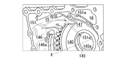
- FIG. 17 to 22 are views for explaining the oil catch portion 15.
- FIG. 17 is a plan view of the fourth box 14 as viewed from the third box 13 side.
- FIG. 18 is a perspective view of the oil catch portion 15 shown in FIG. 17 as viewed from diagonally above.
- FIG. 19 is a plan view of the fourth box 14 as viewed from the third box 13 side.
- FIG. 19 shows a state in which the differential case 50 is arranged.
- FIG. 20 is a perspective view of the oil catch portion 15 shown in FIG. 19 as viewed from diagonally above.
- FIG. 21 is a schematic view of a cross section taken along the line AA in FIG. FIG.
- FIG. 22 is a schematic view illustrating the positional relationship between the oil catch portion 15 and the differential case 50 (first case portion 6, second case portion 7) when the power transmission device 1 is viewed from above.
- hatching is added to clarify the positions of the joint portion 142 of the fourth box 14 and the support wall portion 146.
- the fourth box 14 when viewed from the rotation axis X direction is provided with a support wall portion 146 that surrounds the central opening 145a at intervals.
- the inside of the support wall portion 146 (rotation axis X) is the accommodating portion 140 of the differential case 50 (see FIG. 19).
- a space for the oil catch portion 15 and a space for the breather chamber 16 are formed in the upper part of the fourth box 14.
- a communication port 147 for communicating the oil catch portion 15 and the accommodating portion 140 of the differential case 50 is provided in the region intersecting the vertical line VL.
- the oil catch portion 15 and the breather chamber 16 are located on one side (left side in the figure) and the other side (right side in the figure) with a vertical line VL orthogonal to the rotation axis X, respectively. doing.
- the oil catch portion 15 is arranged at a position offset from the vertical line VL passing through the rotation center (rotation axis X) of the differential case 50.
- the vertical line VL is a vertical line VL based on the installation state of the power transmission device 1 in the vehicle.
- the vertical line VL when viewed from the rotation axis X direction is orthogonal to the rotation axis X.
- the horizontal line HL is a horizontal line HL based on the installation state of the power transmission device 1 in the vehicle.
- the horizontal line HL is orthogonal to the rotation axis X when viewed from the rotation axis X direction (FIG. 17). reference).
- the oil catch portion 15 is formed so as to extend to the back side of the paper surface from the support wall portion 146.
- a support base portion 151 is provided on the lower edge of the oil catch portion 15 so as to project toward the front side of the paper surface.
- the support base portion 151 is provided on the front side of the paper surface of the support wall portion 146 and in the range from the joint portion 142 of the fourth box 14 to the back side of the paper surface.
- the oil catch portion 15 and the accommodating portion 140 of the differential case 50 communicate with each other on the vertical VL side (right side in the drawing) of the oil catch portion 15.
- a mouth 147 is formed.
- the communication port 147 is formed by cutting out a part of the support wall portion 146.
- the communication port 147 is provided in a range that crosses the vertical line VL from the breather chamber 16 side (right side in the figure) to the oil catch portion 15 side (left side in the figure) when viewed from the rotation axis X direction.
- the differential case 50 rotates in the counterclockwise direction CCW around the rotation axis X when viewed from the third box 13 side. .. Therefore, the oil catch portion 15 is located on the downstream side in the rotation direction of the differential case 50.
- the width of the communication port 147 in the circumferential direction is wider on the left side of the vertical line VL than on the right side.
- the left side of the vertical line VL is the downstream side in the rotation direction of the differential case 50, and the right side is the upstream side.
- the outer peripheral position of the rotary orbit of the second shaft portion 446 of the pinion shaft 44 and the outer peripheral position of the rotary orbit of the large pinion gear 431 are offset in the radial direction of the rotation shaft X.
- the outer peripheral position of the rotary orbit of the second shaft portion 446 is located on the inner diameter side of the outer peripheral position of the rotary orbit of the large pinion gear 431. Therefore, there is a space margin on the outer diameter side of the second shaft portion 446. By using this space and providing the oil catch portion 15, the space inside the main body box 10 can be effectively used.
- the second shaft portion 446 projects toward the back side of the small pinion gear 432 when viewed from the motor 2.
- the peripheral member of the second shaft portion 446 (for example, the guide portion 78 of the differential case 50 that supports the second shaft portion 446) is located close to the oil catch portion 15. Therefore, the oil OL (lubricating oil) can be smoothly supplied from the peripheral member to the oil catch portion 15.
- an end portion on the outer diameter side of the oil hole 151a is opened on the inner side of the support base portion 151.
- the oil hole 151a extends in the fourth box 14 toward the inner diameter side.
- the inner diameter side end of the oil hole 151a is open to the inner circumference of the support portion 145.
- the end portion on the inner diameter side of the oil hole 151a is opened between the lip seal RS and the bearing B2.
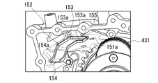
- an oil guide 152 is mounted on the support base portion 151.
- the oil guide 152 has a catch portion 153 and a guide portion 154 extending from the catch portion 153 to the first box 11 side (the front side of the paper surface in FIG. 20).
- the support base portion 151 is located on the radial outer side of the rotation axis X at a position overlapping a part of the differential case 50 (first case portion 6, second case portion 7). It is provided so as to avoid interference with the attached pinion gear 43 (large pinion gear 431).
- the catch portion 153 is provided at a position overlapping the second shaft portion 446 of the pinion shaft 44 when viewed from the radial direction of the rotation shaft X.
- the guide portion 154 is provided at a position where the first shaft portion 445 of the pinion shaft 44 and the large pinion gear 431 overlap with each other.
- a wall portion 153a extending in a direction away from the support base portion 151 (upward) is provided on the outer peripheral edge of the catch portion 153.
- a part of the oil OL scraped up by the differential case 50 that rotates around the rotation axis X is stored in the oil guide 152.
- a notch portion 155 is provided in the wall portion 153a. As shown in FIG. 22, the notch 155 is provided in a region facing the oil hole 151a. A part of the oil OL stored in the catch portion 153 is discharged from the notch portion 155 toward the oil hole 151a.
- the guide portion 154 is inclined downward as the distance from the catch portion 153 increases.
- wall portions 154a and 154a are provided on both sides of the guide portion 154 in the width direction.
- the wall portions 154a and 154a are provided over the entire length of the guide portion 154 in the longitudinal direction.
- the wall portions 154a and 154a are connected to the wall portion 153a surrounding the outer circumference of the catch portion 153. A part of the oil OL stored in the catch portion 153 is also discharged to the guide portion 154 side.
- the guide portion 154 extends toward the second box 12 at a position where it avoids interference with the differential case 50.
- the tip 154b of the guide portion 154 faces the oil hole 126a provided in the wall portion 120 of the second box 12 with a gap in the rotation axis X direction.
- a boss portion 126 surrounding the oil hole 126a is provided on the outer periphery of the wall portion 120.
- One end of the pipe 127 is fitted into the boss portion 126 from the rotation axis X direction.
- the pipe 127 passes through the outside of the second box 12 and extends to the third box 13.
- the other end of the pipe 127 communicates with an oil hole 136a (see FIG. 2) provided in the cylindrical connection wall 136 of the third box.
- the third box 13 is provided with a radial oil passage 137 communicating with the internal space Sc.
- the radial oil passage 137 extends radially downward from the internal space Sc.
- the radial oil passage 137 communicates with the axial oil passage 138 provided in the joint portion 132.
- the axial oil passage 138 communicates with the oil reservoir 128 provided at the lower part of the second box 12 via the communication hole 112a provided at the joint portion 112 of the first box 11.
- the oil sump portion 128 penetrates the inside of the peripheral wall portion 121 in the rotation axis X direction.
- the oil sump 128 is in contact with the gear chamber Sb provided in the fourth box 14.
- the disk-shaped plate member 8 is provided in a direction orthogonal to the rotation axis X. As described above, the plate member 8 divides the gear chamber Sb in the fourth box 14 into the first gear chamber Sb1 on the differential case 50 side and the second gear chamber Sb2 on the motor 2 side.
- FIG. 23 and 24 are views for explaining the plate member 8.
- FIG. 23 is a plan view of the plate member 8 as viewed from the motor 2 side.
- FIG. 24 is a schematic view of a cross section taken along the line AA in FIG. 23.
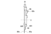
- the plate member 8 has a ring-shaped base 80 when viewed from the motor 2 side.
- a ring-shaped support portion 801 that surrounds the through hole 800 is provided in the central portion of the base portion 80.
- a tubular wall portion 611 of the differential case 50 is supported on the inner circumference of the support portion 801 via a bearing B3.
- connection pieces 81, 82, 83, 84 are provided on the outer peripheral edge 80c of the base 80.
- Each of the connecting pieces 81, 82, 83, 84 extends radially outward from the outer peripheral edge 80c of the base 80.
- Bolt holes 81a, 82a, 83a, 84a are provided in the connection pieces 81, 82, 83, and 84, respectively.
- the connecting piece 81 is provided at a position intersecting the vertical straight line VL at the upper part of the plate member 8.
- the connecting piece 81 extends along the vertical line VL in a direction away from the base 80.
- connection piece 84 is provided below the horizontal line HL.
- the connection piece 84 passes below the horizon HL and passes through the lower edge of the connection piece 83 described above.
- the connecting piece 84 projects downward from a position intersecting a straight line HLa parallel to the horizontal line HL.
- connection piece 85 On the other side of the vertical line VL (on the right side in FIG. 23), the connection piece 85 is provided above the horizontal line HL.
- the connection piece 85 has a predetermined width in the circumferential direction around the rotation axis X.
- a bolt hole 85a is provided at a position of the connecting piece 85 near the vertical line VL.
- a support pin 85b is provided at a position closer to the horizon HL.
- FIG. 25 is a view of the fourth box 14 as viewed from the motor 2 side.
- FIG. 25 shows the arrangement of the step portions 148d, 149d, and 17d that support the outer peripheral edge of the plate member 8.
- FIG. 25 in order to clarify the positions of the peripheral wall portions 148, 149 and the arc-shaped wall portion 17, and the positions of the step portions 148d, 149d, and 17d, they are shown with hatching.
- FIG. 26 and 27 are views for explaining the arrangement of the plate member 8.
- FIG. 26 is a view of the fourth box 14 as viewed from the motor 2 side.
- FIG. 26 shows a state in which the plate member 8 is attached to the fourth box 14.
- FIG. 27 is a schematic cross-sectional view of the plate member 8 cut along the line AA in FIG. 26. Note that FIG. 27 shows a cross section when the stepped pinion gear 43 rotating around the rotation axis X is located below the fourth box 14. Further, a part of the large pinion gear 431 of the stepped pinion gear 43 is shown not in a cross section but in a state viewed from the outer peripheral side. In FIG. 27, hatching is provided on the outer peripheral surface of the tooth portion 431a of the large pinion gear 431.
- peripheral wall portions 148 and 149 are provided in the fourth box 14 when viewed from the rotation axis X direction. These peripheral wall portions 148 and 149 are located on the outer diameter side of the region of the support wall portion 146 where the tooth portions 146a are provided. The peripheral wall portions 148 and 149 are formed in an arc shape centered on the rotation axis X.
- the peripheral wall portion 148 is located below the oil catch portion 15 described above in the vertical VL direction.
- the peripheral wall portion 148 when viewed from the rotation axis X direction is provided in a range that crosses the horizontal line HL passing through the rotation axis X from the upper side to the lower side.
- the upper end portion 148a of the peripheral wall portion 148 is located in the vicinity of the support base portion 151.
- the lower end 148b of the peripheral wall portion 148 is located in the vicinity of the straight line HLa.
- the inner circumference 148c of the peripheral wall portion 148 when viewed from the rotation axis X direction forms an arc shape along the outer circumference of the plate member 8 (base portion 80).
- the inner diameter of the inner circumference 148c of the peripheral wall portion 148 with reference to the rotation axis X is slightly larger than the outer diameter with respect to the rotation axis X of the plate member 8.
- a stepped portion 148d recessed on the back side of the paper surface is provided inside the peripheral wall portion 148.
- boss portions 18 having bolt holes 18a are provided on the outside of the peripheral wall portion 148.
- the boss portions 18 and 18 are integrally formed with the peripheral wall portion 148.
- the boss portions 18 and 18 are provided in the vicinity of the upper end portion 148a side of the peripheral wall portion 148 and the lower end portion 148b, respectively.
- the boss portions 18 and 18 project to the front side of the paper surface from the peripheral wall portion 148.
- the peripheral wall portion 149 is located below the breather chamber 16.
- the peripheral wall portion 149 is located on the back side of the paper surface with respect to the wall portion 160 forming the breather chamber 16.
- the upper end portion 149a of the peripheral wall portion 149 when viewed from the rotation axis X direction is connected to the boss portion 18 on the vertical line VL.
- a side wall portion 159 extending toward the oil catch portion 15 is further connected to the boss portion 18.
- the lower end 149b of the peripheral wall portion 149 is connected to the peripheral wall portion 141 of the fourth box 14 on the lower side of the breather chamber 16.
- the inner circumference 149c of the peripheral wall portion 149 when viewed from the rotation axis X direction forms an arc shape along the outer circumference of the plate member 8 (base portion 80).
- the inner diameter of the inner circumference 149c of the peripheral wall portion 149 with reference to the rotation axis X is slightly larger than the outer diameter of the plate member 8 with reference to the rotation axis X.
- a stepped portion 149d recessed on the back side of the paper surface is provided inside the peripheral wall portion 149.
- Two boss portions 18 having bolt holes 18a are provided on the outside of the peripheral wall portion 149.
- the boss portions 18 and 18 are integrally formed with the peripheral wall portion 149.
- the boss portions 18 and 18 are provided at intervals in the circumferential direction around the rotation axis X.
- the boss portions 18 and 18 are provided on the outer circumference of the upper end portion 148a of the peripheral wall portion 149 and the outer circumference of the region located below the breather chamber 16, respectively.
- the boss portions 18 and 18 project to the front side of the paper surface from the peripheral wall portion 149.
- an arcuate wall portion 17 is provided in a region below the breather chamber 16 and below the horizon HL.
- the arc-shaped wall portion 17 is provided in a positional relationship that is approximately 180 ° out of phase with respect to the peripheral wall portion 148 in the circumferential direction around the rotation axis X.
- the inner circumference 17c of the arcuate wall portion 17 when viewed from the rotation axis X direction forms an arc shape along the outer circumference of the plate member 8 (base portion 80).
- the inner diameter of the inner circumference 17c of the arc-shaped wall portion 17 based on the rotation axis X is slightly larger than the outer diameter of the plate member 8 based on the rotation axis X.
- a boss portion 18 having a bolt hole 18a is formed at a position intersecting the straight line HLa described above. The boss portion 18 projects toward the front side of the paper surface with respect to the arcuate wall portion 17.
- a step portion 17d protrudes from the inner circumference of the boss portion 18 in the X direction of the rotation axis.
- the outer peripheral edge of the plate member 8 (base 80) is attached to the peripheral wall portions 148, 149 step portions 148d, 149d, and the arc-shaped wall portion 17 step portion.
- the 17d is brought into contact with the rotation axis X direction.
- the bolt B penetrating the bolt holes 81a to 85a of the connecting pieces 81 to 85 is screwed into the bolt holes 18a of the corresponding boss portion 18.
- the plate member 8 is fixed to the fourth box 14 (see FIG. 26).
- the lowermost portion 80c'at the outer peripheral edge 80c of the plate member 8 is with the bottom portion 143 of the fourth box 14.
- a clearance CL is provided between them.
- bolt boss portions 141A and 141A are provided on both sides of the lowermost portion 80c'of the plate member 8.
- the bolt boss portions 141A and 141A function as a pair of side wall ribs.
- peripheral wall portions 141a and 141a surrounding the bolt boss portions 141A and 141A bulge into the inside of the fourth box 14.
- the peripheral wall portions 141a and 141a have larger outer diameters with respect to the center line X141 of the bolt boss portion 141A as they are separated from the joint portion 142 when viewed from the rotation axis X direction.
- the first gear chamber Sb1 located on one side of the plate member 8 and the second gear chamber Sb2 located on the other side are the bottom 143 and the plate of the fourth box 14. They communicate with each other via a clearance CL with the member 8.
- the facing wall portion 144 is provided on the back side of the clearance CL when viewed from the motor 2 side (right side in FIG. 27) in the rotation axis X direction.
- the facing wall portion 144 is located on the outer diameter side of the small pinion gear 432.
- the facing wall portion 144 is provided substantially parallel to the base portion 80 of the plate member 8.
- the region on the rotation axis X side of the facing wall portion 144, the outer peripheral edge Lz of the revolution orbit of the large pinion gear 431, and the lowermost portion 80c'of the plate member 8 have a portion that overlaps in the rotation axis X direction. .. Therefore, when viewed from the rotation axis X direction, the facing wall portion 144, the large pinion gear 431, and the plate member 8 partially overlap each other.
- a space Sw surrounded by the facing wall portion 144 and the peripheral wall portions 141a and 141a of the bolt boss portion 141A is formed on the bottom portion 143 side (lower side) when viewed from the plate member 8.
- This space Sw is located below the orbit of the large pinion gear 431 of the stepped pinion gear 43.
- the space Sw is located between the outer circumference of the large pinion gear 431 and the bottom 143.
- the space Sw is open to the wall portion 120 side of the second box 12.
- the space Sw communicates with the oil sump portion 128 via the opening 143a.
- the space Sw in the area on the bottom 143 side (lower side) of the fourth box 14 becomes the first gear chamber Sb1 and the second gear chamber Sb2 partitioned by the plate member 8. It is designed to function as a communication port for communicating with. Further, the second gear chamber Sb2 communicates with the oil sump portion 128 via the opening 143a.
- a "helical gear” is adopted as the large pinion gear 431 of the stepped pinion gear 43.
- the tooth portion 431a provided on the outer periphery thereof is inclined by a predetermined angle ⁇ with respect to the rotation axis (axis line X1) of the stepped pinion gear 43.
- the stepped pinion gear 43 transmits the rotational driving force of the motor 2 via the power transmission path.
- the stepped pinion gear 43 rotates (revolves) around the axis X1 in the direction of the arrow in the figure while rotating around the axis X1 in the direction of the arrow in the figure.
- the large pinion gear 431 that rotates around the axis X1 moves the surrounding oil OL toward the bottom 143 side by the centrifugal force due to the rotation.
- the tooth portion 431a of the large pinion gear 431 has an inclination of the tooth portion 431a with respect to the axis X1 so that the oil OL on the outer peripheral side (bottom portion 143) side of the large pinion gear 431 is on the plate member 8 (wall portion 120) side. It is set to form a flow toward. Therefore, the oil OL moves to the bottom 143 side by the centrifugal force due to the rotation of the large pinion gear 431 and reaches the space Sw. The oil OL that has reached the space Sw moves to the plate member 8 side by the flow formed by the tooth portion 431a.
- the peripheral wall portions 141a and 141a of the bolt boss portion 141A are located on both sides of the space Sw.
- the peripheral wall portions 141a and 141a of the bolt boss portion 141A are provided with facing wall portions 144 on the back side of the plate member 8. Therefore, the space Sw formed on the bottom portion 143 side of the large pinion gear 431 is surrounded by the peripheral wall portions 141a and 141a and the facing wall portion 144. Therefore, the moving direction of the oil OL that has reached the space Sw is largely restricted to the second gear chamber Sb2 side.
- the oil reservoir 128 is located on the extension of the space Sw, the oil OL moving to the second gear chamber Sb2 side is not significantly obstructed by the flow, and the second gear chamber Sb2 and the oil reservoir are not significantly obstructed. It flows into 128. Therefore, most of the oil OL that has moved into the space Sw passes through the clearance CL between the plate member 8 and the bottom 143 without flowing back to the large pinion gear 431 side, and passes through the clearance CL between the plate member 8 and the bottom 143 to the wall 120 side (second) of the second box 12. It is discharged to the gear chamber Sb2 and the oil sump 128).
- the amount of oil OL on the first gear chamber Sb1 side becomes lower than that on the second gear chamber Sb2 side, and the stirring resistance of the differential case 50 rotating around the rotation axis X in the first gear chamber Sb1 can be reduced.
- the planetary reduction gear 4 As shown in FIG. 1, in the power transmission device 1, the planetary reduction gear 4, the differential mechanism 5, and the drive shafts 9 (9A, 9B) are provided along the transmission path of the output rotation of the motor 2. ing.
- a park gear 30 (see FIG. 2) of the park lock mechanism 3 is provided between the motor 2 and the planetary reduction gear 4 in the power transmission path.
- the sun gear 41 is an input unit for the output rotation of the motor 2.
- the differential case 50 that supports the stepped pinion gear 43 serves as an output unit for the input rotation.
- the stepped pinion gear 43 (large pinion gear 431, small pinion gear 432) rotates around the axis X1 by the rotation input from the sun gear 41 side. ..
- the small pinion gear 432 of the stepped pinion gear 43 meshes with the ring gear 42 fixed to the inner circumference of the fourth box 14. Therefore, the stepped pinion gear 43 revolves around the rotation axis X while rotating around the axis X1. That is, the rotation shaft X is also the revolution shaft of the stepped pinion gear 43.
- the outer diameter R2 of the small pinion gear 432 of the stepped pinion gear 43 is smaller than the outer diameter R1 of the large pinion gear 431 (see FIG. 3).
- the differential case 50 first case portion 6, second case portion 7) that supports the stepped pinion gear 43 rotates around the rotation axis X at a rotation speed lower than the rotation input from the motor 2 side. Therefore, the rotation input to the sun gear 41 of the planetary reduction gear 4 is greatly reduced by the stepped pinion gear 43. The reduced rotation is output to the differential case 50 (differential mechanism 5).
- the lubricating oil OL is stored inside the fourth box 14. Therefore, the stored oil OL is scraped up by the differential case 50 that rotates around the rotation axis X when the output rotation of the motor 2 is transmitted. Due to the oil OL scraped up, the meshing portion between the sun gear 41 and the large pinion gear 431, the meshing portion between the small pinion gear 432 and the ring gear 42, and the meshing portion between the pinion mate gear 52 and the side gears 54A and 54B are formed. Be lubricated.
- the differential case 50 rotates in the counterclockwise direction CCW around the rotation axis X when viewed from the third box 13 side.
- An oil catch portion 15 is provided on the upper portion of the fourth box 14.
- the oil catch portion 15 is located on the downstream side in the rotation direction of the differential case 50. Most of the oil OL scraped up by the differential case 50 flows into the oil catch portion 15.
- an oil guide 152 mounted on the support base portion 151 is provided in the oil catch portion 15.
- the guide portion 154 and the catch portion 153 of the oil guide 152 are located on the radial outside of the first case portion 6 of the differential case 50 and on the radial outside of the second case portion 7 of the differential case 50. Therefore, most of the oil that has been scraped up by the differential case 50 and has flowed into the oil catch portion 15 is captured by the oil guide 152.
- a part of the oil OL captured by the oil guide 152 is discharged from the notch 155 provided in the wall portion 153a and flows into the oil hole 151a having one end opened on the upper surface of the support base portion 151.
- the inner diameter side end of the oil hole 151a is open to the inner circumference of the support portion 145 (see FIG. 2). Therefore, the oil OL that has flowed into the oil hole 151a is discharged into the gap Rx between the inner circumference of the support portion 145 of the fourth box 14 and the cylinder wall portion 540 of the side gear 54B.
- the oil OL that lubricates the bearing B2 moves to the outer diameter side by the centrifugal force due to the rotation of the differential case 50.
- a slit 710 is provided along the inner circumference of the peripheral wall portion 73. Further movement of the oil OL to the outer diameter side is hindered by the peripheral wall portion 73.
- the oil OL passes through the slit 710 toward the first case portion 6 side.
- the oil passage 781 in the case is open on the inner circumference of the guide portion 78.
- a part of the oil OL that has passed through the slit 710 flows into the oil passage 781 in the case due to the centrifugal force due to the rotation of the differential case.
- the oil OL that has flowed into the oil passage 781 in the case flows into the in-shaft oil passage 440 of the pinion shaft 44 through the introduction passage 441.
- the oil OL that has flowed into the in-shaft oil passage 440 is discharged radially outward from the oil holes 442 and 443.
- the discharged oil OL lubricates the needle bearing NB extrapolated to the pinion shaft 44.
- a part of the oil OL discharged into the gap Rx passes through the oil groove 721 provided on the inner circumference of the cylinder wall portion 72 of the second case portion 7.
- the oil OL that has passed through the oil groove 721 is supplied to the washer 55 that supports the back surface of the side gear 54B to lubricate the washer 55. Further, it passes through the oil groove 712 provided in the base portion 71 of the second case portion 7 and the oil groove 742 provided in the arc portion 741.
- the oil OL that has passed through the oil groove 742 is supplied to the spherical washer 53 that supports the back surface of the pinion mate gear 52, and lubricates the spherical washer 53.
- the oil OL that did not flow into the oil hole 126a travels along the wall portion 120 of the second box 12 and moves toward the lower side of the fourth box 14. As shown in FIG. 2, in the fourth box 14, the space between the wall portion 120 and the plate member 8 is the second gear chamber Sb2. The park gear 30 of the park lock mechanism 3 is located in the second gear chamber Sb2. Therefore, the oil OL that has not flowed into the oil hole 126a lubricates the park gear 30 when moving downward in the second gear chamber Sb2.
- a boss portion 126 surrounding the oil hole 126a is provided on the outer periphery of the wall portion 120.
- One end of the pipe 127 is fitted into the boss portion 126 from the rotation axis X direction. Therefore, the oil OL that has flowed into the oil hole 126a of the second box 12 flows into the pipe 127.
- the pipe 127 passes through the outside of the second box 12 and extends to the third box 13.
- the other end of the pipe 127 communicates with an oil hole 136a (see FIG. 2) provided in the cylindrical connection wall 136 of the third box.
- a part of the oil OL that has reached the oil catch portion 15 is supplied to the internal space Sc of the connection wall 136 through the guide portion 154 and the pipe 127.
- the oil OL discharged from the oil hole 136a into the internal space Sc is stored in the internal space Sc.
- the oil OL lubricates the bearing B4 supported by the peripheral wall portion 131 of the third box 13.
- a part of the oil OL discharged into the internal space Sc moves to the other end 20b side of the motor shaft 20 through the gap between the outer circumference of the drive shaft 9A and the inner circumference of the motor shaft 20.
- the other end 20b of the motor shaft 20 is inserted inside the tubular wall portion 541 of the side gear 54A.
- a connecting path 542 communicating with the back surface of the side gear 54A is provided on the inner circumference of the cylinder wall portion 541. Therefore, a part of the oil OL that has moved to the other end 20b side of the motor shaft 20 and has been discharged to the inside of the cylinder wall portion 541 passes through the connecting path 542.
- the oil OL that has passed through the communication passage 542 is supplied to the washer 55 on the back surface of the side gear 54A to lubricate the washer 55.
- the oil OL that lubricates the washer 55 on the back surface of the side gear 54A passes through the oil groove 662 provided in the gear support portion 66 of the first case portion 6 and the oil groove 642 provided in the arc portion 641.
- the oil OL that has passed through the oil groove 642 is supplied to the spherical washer 53 that supports the back surface of the pinion mate gear 52, and lubricates the spherical washer 53.
- the internal space Sc of the third box 13 includes a radial oil passage 137, an axial oil passage 138, a communication hole 112a, and an oil reservoir provided at the lower part of the second box 12. It communicates with the second gear chamber Sb2 provided in the fourth box 14 via 128. Therefore, the oil OL in the internal space Sc is held at the same height position as the oil OL stored in the fourth box 14.
- a tooth portion 431a inclined by a predetermined angle ⁇ with respect to the axis X1 is provided on the outer circumference of the large pinion gear 431. Then, the direction in which the tooth portion 431a is inclined with respect to the axis X1 is the direction in which the oil OL on the outer peripheral side (bottom portion 143) side of the large pinion gear 431 forms a flow toward the plate member 8 (wall portion 120) side. It is set. Therefore, the oil OL that has moved to the bottom 143 side due to the centrifugal force due to the rotation of the large pinion gear 431 moves to the plate member 8 side due to the flow of the oil OL formed by the tooth portion 431a.
- peripheral wall portions 141a and 141a of the bolt boss portion 141A are located on both sides of the space Sw when viewed from the rotation axis X direction.
- the peripheral wall portions 141a and 141a of the bolt boss portion 141A are provided with facing wall portions 144 on the back side of the plate member 8. Therefore, the space Sw formed on the bottom portion 143 side of the large pinion gear 431 is surrounded by the peripheral wall portions 141a and 141a and the facing wall portion 144. Therefore, most of the oil OL that has moved into the space SW is discharged to the wall portion 120 side of the second box 12 through the clearance CL between the plate member 8 and the bottom portion 143 without returning to the large pinion gear 431 side. To.
- the power transmission device 1 has the following configuration.
- the power transmission device 1 is A stepped pinion gear 43 (pinion gear) having a large pinion gear 431 and a small pinion gear 432, and A wall portion 120 that overlaps the orbit of the large pinion gear 431 in the X direction (axial direction) of the rotation axis, and A plate member 8 (plate) provided between the wall portion 120 and the large pinion gear 431, and It has a plate member 8 and a bottom portion 143 provided at a lower portion of the revolution orbit of the large pinion gear 431 via a clearance CL.
- the oil OL lubricating oil
- the oil level height on the large pinion gear 431 side (first gear chamber Sb1) as viewed from the plate member 8 can be lowered. Therefore, the stirring resistance can be reduced.
- the power transmission device 1 has the following configuration. (2) The facing wall portion 144 facing the clearance CL is provided on the outer circumference (outer diameter side) of the small pinion gear 432.
- the facing wall portion 144 regulates the flow of oil OL toward the small pinion gear 432 side, and the oil OL can be easily supplied to the wall portion 120 side.
- the power transmission device 1 has the following configuration. (3)
- the facing wall portion 144 has a portion that overlaps the revolution trajectory of the plate member 8 and the large pinion gear 431 in the rotation axis X direction.
- the power transmission device 1 has the following configuration.
- the large pinion gear 431 is a helical gear.
- the direction of the helical gear is set so that the oil OL is introduced to the wall portion 120 side as the large pinion gear 431 rotates.
- the oil OL can be efficiently sent to the wall portion 120 side as the large pinion gear 431 rotates.
- the power transmission device 1 has the following configuration. (5)
- the bottom portion 143 is provided with bolt boss portions 141A and 141A that function as a pair of side wall ribs extending in the rotation axis X direction. When viewed from the rotation axis X direction, the bolt boss portions 141A and 141A are located on both sides of the plate member 8 with the lowermost portion 80c'in between.
- the bolt boss portions 141A and 141A that function as the side wall ribs can smoothly feed the oil OL that has moved to the bottom portion 143 side by the rotating large pinion gear 431 to the wall portion 120 side.
- the bolt boss portion 141A for fastening bolts is used as the side wall rib.
- the oil OL may be guided to the wall portion 120 side by using a rib provided separately from the bolt boss portion 141A.
- the power transmission device 1 has the following configuration. (6)
- the bottom portion 143 is provided with an opening 143a facing the clearance CL in the rotation axis X direction.
- the opening 143a allows the lubricating oil to flow slightly behind the surface of the wall portion 120, so that the backflow of the oil OL passing under the plate member 8 can be suppressed.
- the power transmission device 1 has the following configuration. (7) In the power transmission device 1, the motor 2 is arranged on the upstream side of the sun gear 41 that meshes with the large pinion gear 431 on the transmission path of the rotational driving force. The sun gear 41 overlaps in the rotation axis X direction.
- the power transmission device 1 is a power transmission device for a single-axis electric vehicle, and can provide a compact power transmission device.
- the motor 2 is provided on the back side (right side in FIG. 2) of the wall portion 120 when viewed from the fourth box 14 is illustrated, but the motor 2 is located on the front side of the wall portion 120. It may be provided.
- Power transmission device 120 Wall portion 141A: Bolt boss portion (side wall rib) 143: Bottom 143a: Opening 144: Opposing wall 2: Motor 41: Sun gear 43: Stepped pinion gear (pinion gear) 431: Large pinion gear 432: Small pinion gear 8: Plate member (plate) OL: Oil (lubricating oil) X: Rotation axis
Priority Applications (4)
| Application Number | Priority Date | Filing Date | Title |
|---|---|---|---|
| CN202080091134.2A CN114901970B (zh) | 2019-12-30 | 2020-12-07 | 动力传递装置 |
| EP20908453.2A EP4086479A4 (de) | 2019-12-30 | 2020-12-07 | Stromübertragungsvorrichtung |
| US17/789,337 US11906035B2 (en) | 2019-12-30 | 2020-12-07 | Power transmission device |
| JP2021568462A JP7109875B2 (ja) | 2019-12-30 | 2020-12-07 | 動力伝達装置 |
Applications Claiming Priority (2)
| Application Number | Priority Date | Filing Date | Title |
|---|---|---|---|
| JP2019240047 | 2019-12-30 | ||
| JP2019-240047 | 2019-12-30 |
Publications (1)
| Publication Number | Publication Date |
|---|---|
| WO2021137284A1 true WO2021137284A1 (ja) | 2021-07-08 |
Family
ID=76687111
Family Applications (1)
| Application Number | Title | Priority Date | Filing Date |
|---|---|---|---|
| PCT/JP2020/045426 WO2021137284A1 (ja) | 2019-12-30 | 2020-12-07 | 動力伝達装置 |
Country Status (5)
| Country | Link |
|---|---|
| US (1) | US11906035B2 (de) |
| EP (1) | EP4086479A4 (de) |
| JP (1) | JP7109875B2 (de) |
| CN (1) | CN114901970B (de) |
| WO (1) | WO2021137284A1 (de) |
Cited By (2)
| Publication number | Priority date | Publication date | Assignee | Title |
|---|---|---|---|---|
| WO2023190421A1 (ja) * | 2022-03-29 | 2023-10-05 | 株式会社アイシン | 車両用駆動装置 |
| WO2023202841A1 (de) * | 2022-04-20 | 2023-10-26 | Mercedes-Benz Group AG | Elektrische antriebseinrichtung für ein kraftfahrzeug, insbesondere für einen kraftwagen |
Citations (4)
| Publication number | Priority date | Publication date | Assignee | Title |
|---|---|---|---|---|
| JPH08240254A (ja) | 1995-03-06 | 1996-09-17 | Toyota Motor Corp | 電気自動車用動力伝達装置 |
| JP2007120519A (ja) * | 2005-10-25 | 2007-05-17 | Honda Motor Co Ltd | 動力伝達装置の潤滑装置 |
| JP2011174582A (ja) * | 2010-02-25 | 2011-09-08 | Toyota Motor Corp | 車両用動力伝達装置 |
| JP2012082930A (ja) * | 2010-10-14 | 2012-04-26 | Toyota Motor Corp | 電気自動車用駆動装置 |
Family Cites Families (10)
| Publication number | Priority date | Publication date | Assignee | Title |
|---|---|---|---|---|
| US2968190A (en) * | 1958-02-17 | 1961-01-17 | Borg Warner | Transmission mechanism |
| JPS589560U (ja) * | 1981-07-13 | 1983-01-21 | トヨタ自動車株式会社 | トランスミツシヨンのハウジング |
| CA2041869A1 (en) * | 1990-10-19 | 1992-04-20 | Bruce A. Churchill | Slinger lubrication process |
| JP3073539B2 (ja) * | 1991-03-15 | 2000-08-07 | マツダ株式会社 | 変速機の潤滑構造 |
| JPH10184857A (ja) * | 1996-12-20 | 1998-07-14 | Aisin Aw Co Ltd | プラネタリギヤ機構の潤滑装置 |
| JP4538253B2 (ja) * | 2004-03-25 | 2010-09-08 | 本田技研工業株式会社 | モータ式動力装置 |
| JP6135419B2 (ja) * | 2013-09-13 | 2017-05-31 | トヨタ自動車株式会社 | ハイブリッド車両用動力伝達装置 |
| DE102014200675A1 (de) * | 2014-01-16 | 2015-07-16 | Zf Friedrichshafen Ag | Stufenplanet mit innenliegender Lagerung |
| CA2941222C (en) * | 2014-03-10 | 2018-07-03 | Honda Motor Co., Ltd. | Lubricating structure for differential device |
| JP6580726B2 (ja) * | 2018-02-13 | 2019-09-25 | 本田技研工業株式会社 | 動力伝達装置 |
-
2020
- 2020-12-07 CN CN202080091134.2A patent/CN114901970B/zh active Active
- 2020-12-07 US US17/789,337 patent/US11906035B2/en active Active
- 2020-12-07 EP EP20908453.2A patent/EP4086479A4/de active Pending
- 2020-12-07 JP JP2021568462A patent/JP7109875B2/ja active Active
- 2020-12-07 WO PCT/JP2020/045426 patent/WO2021137284A1/ja unknown
Patent Citations (4)
| Publication number | Priority date | Publication date | Assignee | Title |
|---|---|---|---|---|
| JPH08240254A (ja) | 1995-03-06 | 1996-09-17 | Toyota Motor Corp | 電気自動車用動力伝達装置 |
| JP2007120519A (ja) * | 2005-10-25 | 2007-05-17 | Honda Motor Co Ltd | 動力伝達装置の潤滑装置 |
| JP2011174582A (ja) * | 2010-02-25 | 2011-09-08 | Toyota Motor Corp | 車両用動力伝達装置 |
| JP2012082930A (ja) * | 2010-10-14 | 2012-04-26 | Toyota Motor Corp | 電気自動車用駆動装置 |
Non-Patent Citations (1)
| Title |
|---|
| See also references of EP4086479A4 |
Cited By (2)
| Publication number | Priority date | Publication date | Assignee | Title |
|---|---|---|---|---|
| WO2023190421A1 (ja) * | 2022-03-29 | 2023-10-05 | 株式会社アイシン | 車両用駆動装置 |
| WO2023202841A1 (de) * | 2022-04-20 | 2023-10-26 | Mercedes-Benz Group AG | Elektrische antriebseinrichtung für ein kraftfahrzeug, insbesondere für einen kraftwagen |
Also Published As
| Publication number | Publication date |
|---|---|
| US11906035B2 (en) | 2024-02-20 |
| EP4086479A1 (de) | 2022-11-09 |
| CN114901970B (zh) | 2023-08-08 |
| JPWO2021137284A1 (de) | 2021-07-08 |
| JP7109875B2 (ja) | 2022-08-01 |
| CN114901970A (zh) | 2022-08-12 |
| EP4086479A4 (de) | 2023-09-13 |
| US20230044400A1 (en) | 2023-02-09 |
Similar Documents
| Publication | Publication Date | Title |
|---|---|---|
| WO2021137289A1 (ja) | 動力伝達装置 | |
| WO2021137284A1 (ja) | 動力伝達装置 | |
| WO2021157235A1 (ja) | 動力伝達装置 | |
| JP2021107737A (ja) | 動力伝達装置 | |
| WO2021137278A1 (ja) | 動力伝達装置 | |
| WO2021137281A1 (ja) | 動力伝達装置 | |
| JP7350450B2 (ja) | 動力伝達装置 | |
| WO2021137288A1 (ja) | 動力伝達装置 | |
| WO2021137290A1 (ja) | 動力伝達装置 | |
| WO2021137287A1 (ja) | 動力伝達装置 | |
| WO2021137280A1 (ja) | 動力伝達装置 | |
| WO2021137279A1 (ja) | 動力伝達装置 | |
| JP7371310B2 (ja) | 動力伝達装置 | |
| JP7073031B2 (ja) | 動力伝達装置 | |
| JP7375262B2 (ja) | 動力伝達装置 | |
| JP7350451B2 (ja) | 動力伝達装置 | |
| JP7350452B2 (ja) | 動力伝達装置 | |
| WO2021137282A1 (ja) | 動力伝達装置 |
Legal Events
| Date | Code | Title | Description |
|---|---|---|---|
| 121 | Ep: the epo has been informed by wipo that ep was designated in this application |
Ref document number: 20908453 Country of ref document: EP Kind code of ref document: A1 |
|
| ENP | Entry into the national phase |
Ref document number: 2021568462 Country of ref document: JP Kind code of ref document: A |
|
| NENP | Non-entry into the national phase |
Ref country code: DE |
|
| ENP | Entry into the national phase |
Ref document number: 2020908453 Country of ref document: EP Effective date: 20220801 |