WO2021131877A1 - 二次電池、及びその製造方法 - Google Patents
二次電池、及びその製造方法 Download PDFInfo
- Publication number
- WO2021131877A1 WO2021131877A1 PCT/JP2020/046639 JP2020046639W WO2021131877A1 WO 2021131877 A1 WO2021131877 A1 WO 2021131877A1 JP 2020046639 W JP2020046639 W JP 2020046639W WO 2021131877 A1 WO2021131877 A1 WO 2021131877A1
- Authority
- WO
- WIPO (PCT)
- Prior art keywords
- separator
- electrode
- secondary battery
- pole
- adhesive
- Prior art date
Links
- 238000004519 manufacturing process Methods 0.000 title claims description 10
- 239000000853 adhesive Substances 0.000 claims abstract description 202
- 230000001070 adhesive effect Effects 0.000 claims abstract description 202
- 239000000463 material Substances 0.000 claims description 59
- 238000004804 winding Methods 0.000 claims description 24
- 238000000034 method Methods 0.000 claims description 22
- 239000011149 active material Substances 0.000 claims description 12
- 230000010220 ion permeability Effects 0.000 claims description 10
- 238000007731 hot pressing Methods 0.000 claims description 7
- 239000011255 nonaqueous electrolyte Substances 0.000 claims description 6
- 239000010410 layer Substances 0.000 description 91
- 239000011162 core material Substances 0.000 description 73
- 239000008151 electrolyte solution Substances 0.000 description 47
- 239000000203 mixture Substances 0.000 description 44
- 238000007789 sealing Methods 0.000 description 42
- 239000002245 particle Substances 0.000 description 41
- 239000007788 liquid Substances 0.000 description 39
- 229920005989 resin Polymers 0.000 description 16
- 239000011347 resin Substances 0.000 description 16
- 239000011230 binding agent Substances 0.000 description 14
- 229910052751 metal Inorganic materials 0.000 description 14
- 238000003825 pressing Methods 0.000 description 14
- 239000002002 slurry Substances 0.000 description 14
- 239000002184 metal Substances 0.000 description 13
- 238000002347 injection Methods 0.000 description 12
- 239000007924 injection Substances 0.000 description 12
- 230000002093 peripheral effect Effects 0.000 description 12
- OKTJSMMVPCPJKN-UHFFFAOYSA-N Carbon Chemical group [C] OKTJSMMVPCPJKN-UHFFFAOYSA-N 0.000 description 11
- 239000011248 coating agent Substances 0.000 description 11
- 238000000576 coating method Methods 0.000 description 11
- 238000009826 distribution Methods 0.000 description 11
- 238000012360 testing method Methods 0.000 description 11
- -1 Lithium transition metal Chemical class 0.000 description 10
- 150000002484 inorganic compounds Chemical class 0.000 description 10
- 229910010272 inorganic material Inorganic materials 0.000 description 10
- 239000012466 permeate Substances 0.000 description 10
- 229910052782 aluminium Inorganic materials 0.000 description 9
- 239000003792 electrolyte Substances 0.000 description 9
- 230000008569 process Effects 0.000 description 9
- 238000003466 welding Methods 0.000 description 9
- 230000035699 permeability Effects 0.000 description 8
- 239000007774 positive electrode material Substances 0.000 description 8
- 239000012790 adhesive layer Substances 0.000 description 7
- XAGFODPZIPBFFR-UHFFFAOYSA-N aluminium Chemical compound [Al] XAGFODPZIPBFFR-UHFFFAOYSA-N 0.000 description 7
- 239000011888 foil Substances 0.000 description 7
- 239000007789 gas Substances 0.000 description 7
- 239000007773 negative electrode material Substances 0.000 description 7
- 229920000098 polyolefin Polymers 0.000 description 7
- 238000010248 power generation Methods 0.000 description 7
- 239000011241 protective layer Substances 0.000 description 7
- 150000003839 salts Chemical class 0.000 description 7
- 239000010949 copper Substances 0.000 description 6
- 230000000694 effects Effects 0.000 description 6
- 229910002804 graphite Inorganic materials 0.000 description 6
- 239000010439 graphite Substances 0.000 description 6
- 229910000838 Al alloy Inorganic materials 0.000 description 5
- RYGMFSIKBFXOCR-UHFFFAOYSA-N Copper Chemical compound [Cu] RYGMFSIKBFXOCR-UHFFFAOYSA-N 0.000 description 5
- HBBGRARXTFLTSG-UHFFFAOYSA-N Lithium ion Chemical compound [Li+] HBBGRARXTFLTSG-UHFFFAOYSA-N 0.000 description 5
- 239000002033 PVDF binder Substances 0.000 description 5
- 229910052802 copper Inorganic materials 0.000 description 5
- 238000001035 drying Methods 0.000 description 5
- 238000011156 evaluation Methods 0.000 description 5
- 229910052744 lithium Inorganic materials 0.000 description 5
- 229910001416 lithium ion Inorganic materials 0.000 description 5
- 229920002981 polyvinylidene fluoride Polymers 0.000 description 5
- 229920002134 Carboxymethyl cellulose Polymers 0.000 description 4
- SECXISVLQFMRJM-UHFFFAOYSA-N N-Methylpyrrolidone Chemical compound CN1CCCC1=O SECXISVLQFMRJM-UHFFFAOYSA-N 0.000 description 4
- 239000003125 aqueous solvent Substances 0.000 description 4
- 239000002905 metal composite material Substances 0.000 description 4
- 230000004048 modification Effects 0.000 description 4
- 238000012986 modification Methods 0.000 description 4
- 229910052759 nickel Inorganic materials 0.000 description 4
- 229920003048 styrene butadiene rubber Polymers 0.000 description 4
- 229910052723 transition metal Inorganic materials 0.000 description 4
- 239000004925 Acrylic resin Substances 0.000 description 3
- 229920000178 Acrylic resin Polymers 0.000 description 3
- 229910000881 Cu alloy Inorganic materials 0.000 description 3
- 239000004698 Polyethylene Substances 0.000 description 3
- 230000005856 abnormality Effects 0.000 description 3
- 239000006230 acetylene black Substances 0.000 description 3
- PNEYBMLMFCGWSK-UHFFFAOYSA-N aluminium oxide Inorganic materials [O-2].[O-2].[O-2].[Al+3].[Al+3] PNEYBMLMFCGWSK-UHFFFAOYSA-N 0.000 description 3
- 229910001593 boehmite Inorganic materials 0.000 description 3
- 239000002388 carbon-based active material Substances 0.000 description 3
- 239000004020 conductor Substances 0.000 description 3
- 238000006073 displacement reaction Methods 0.000 description 3
- FAHBNUUHRFUEAI-UHFFFAOYSA-M hydroxidooxidoaluminium Chemical compound O[Al]=O FAHBNUUHRFUEAI-UHFFFAOYSA-M 0.000 description 3
- 229910052748 manganese Inorganic materials 0.000 description 3
- 239000011572 manganese Substances 0.000 description 3
- 229920000058 polyacrylate Polymers 0.000 description 3
- 229920002239 polyacrylonitrile Polymers 0.000 description 3
- 229920000573 polyethylene Polymers 0.000 description 3
- 229920001721 polyimide Polymers 0.000 description 3
- KMTRUDSVKNLOMY-UHFFFAOYSA-N Ethylene carbonate Chemical compound O=C1OCCO1 KMTRUDSVKNLOMY-UHFFFAOYSA-N 0.000 description 2
- YCKRFDGAMUMZLT-UHFFFAOYSA-N Fluorine atom Chemical compound [F] YCKRFDGAMUMZLT-UHFFFAOYSA-N 0.000 description 2
- 229910013870 LiPF 6 Inorganic materials 0.000 description 2
- 229920003171 Poly (ethylene oxide) Polymers 0.000 description 2
- 239000004642 Polyimide Substances 0.000 description 2
- 239000004372 Polyvinyl alcohol Substances 0.000 description 2
- VYPSYNLAJGMNEJ-UHFFFAOYSA-N Silicium dioxide Chemical compound O=[Si]=O VYPSYNLAJGMNEJ-UHFFFAOYSA-N 0.000 description 2
- 229920002125 Sokalan® Polymers 0.000 description 2
- 239000002174 Styrene-butadiene Substances 0.000 description 2
- GWEVSGVZZGPLCZ-UHFFFAOYSA-N Titan oxide Chemical compound O=[Ti]=O GWEVSGVZZGPLCZ-UHFFFAOYSA-N 0.000 description 2
- MCMNRKCIXSYSNV-UHFFFAOYSA-N Zirconium dioxide Chemical compound O=[Zr]=O MCMNRKCIXSYSNV-UHFFFAOYSA-N 0.000 description 2
- 229910021383 artificial graphite Inorganic materials 0.000 description 2
- 238000004364 calculation method Methods 0.000 description 2
- 239000001768 carboxy methyl cellulose Substances 0.000 description 2
- 235000010948 carboxy methyl cellulose Nutrition 0.000 description 2
- 239000008112 carboxymethyl-cellulose Substances 0.000 description 2
- 230000008859 change Effects 0.000 description 2
- 238000006243 chemical reaction Methods 0.000 description 2
- 239000011247 coating layer Substances 0.000 description 2
- 239000002131 composite material Substances 0.000 description 2
- 229920001577 copolymer Polymers 0.000 description 2
- 238000010586 diagram Methods 0.000 description 2
- 239000007772 electrode material Substances 0.000 description 2
- 239000000839 emulsion Substances 0.000 description 2
- JBTWLSYIZRCDFO-UHFFFAOYSA-N ethyl methyl carbonate Chemical compound CCOC(=O)OC JBTWLSYIZRCDFO-UHFFFAOYSA-N 0.000 description 2
- 229910052731 fluorine Inorganic materials 0.000 description 2
- 239000011737 fluorine Substances 0.000 description 2
- 230000001771 impaired effect Effects 0.000 description 2
- 239000010954 inorganic particle Substances 0.000 description 2
- 238000010030 laminating Methods 0.000 description 2
- 230000007246 mechanism Effects 0.000 description 2
- 239000000155 melt Substances 0.000 description 2
- 238000002844 melting Methods 0.000 description 2
- 230000008018 melting Effects 0.000 description 2
- 239000012046 mixed solvent Substances 0.000 description 2
- 229920000642 polymer Polymers 0.000 description 2
- 229920005672 polyolefin resin Polymers 0.000 description 2
- 229920001343 polytetrafluoroethylene Polymers 0.000 description 2
- 239000004810 polytetrafluoroethylene Substances 0.000 description 2
- 229920002451 polyvinyl alcohol Polymers 0.000 description 2
- 238000007639 printing Methods 0.000 description 2
- 239000002409 silicon-based active material Substances 0.000 description 2
- 238000007581 slurry coating method Methods 0.000 description 2
- 239000000126 substance Substances 0.000 description 2
- 239000002344 surface layer Substances 0.000 description 2
- XLYOFNOQVPJJNP-UHFFFAOYSA-N water Substances O XLYOFNOQVPJJNP-UHFFFAOYSA-N 0.000 description 2
- UFHFLCQGNIYNRP-UHFFFAOYSA-N Hydrogen Chemical compound [H][H] UFHFLCQGNIYNRP-UHFFFAOYSA-N 0.000 description 1
- 229910001228 Li[Ni1/3Co1/3Mn1/3]O2 (NCM 111) Inorganic materials 0.000 description 1
- WHXSMMKQMYFTQS-UHFFFAOYSA-N Lithium Chemical compound [Li] WHXSMMKQMYFTQS-UHFFFAOYSA-N 0.000 description 1
- 239000004962 Polyamide-imide Substances 0.000 description 1
- 239000004743 Polypropylene Substances 0.000 description 1
- SOXUFMZTHZXOGC-UHFFFAOYSA-N [Li].[Mn].[Co].[Ni] Chemical compound [Li].[Mn].[Co].[Ni] SOXUFMZTHZXOGC-UHFFFAOYSA-N 0.000 description 1
- 150000001408 amides Chemical class 0.000 description 1
- 239000004760 aramid Substances 0.000 description 1
- 229920003235 aromatic polyamide Polymers 0.000 description 1
- 229910052796 boron Inorganic materials 0.000 description 1
- DQXBYHZEEUGOBF-UHFFFAOYSA-N but-3-enoic acid;ethene Chemical compound C=C.OC(=O)CC=C DQXBYHZEEUGOBF-UHFFFAOYSA-N 0.000 description 1
- QHIWVLPBUQWDMQ-UHFFFAOYSA-N butyl prop-2-enoate;methyl 2-methylprop-2-enoate;prop-2-enoic acid Chemical compound OC(=O)C=C.COC(=O)C(C)=C.CCCCOC(=O)C=C QHIWVLPBUQWDMQ-UHFFFAOYSA-N 0.000 description 1
- 229910052799 carbon Inorganic materials 0.000 description 1
- 239000003575 carbonaceous material Substances 0.000 description 1
- 229920002678 cellulose Polymers 0.000 description 1
- 239000001913 cellulose Substances 0.000 description 1
- 239000003795 chemical substances by application Substances 0.000 description 1
- 229910052804 chromium Inorganic materials 0.000 description 1
- 230000000052 comparative effect Effects 0.000 description 1
- 150000001875 compounds Chemical class 0.000 description 1
- 239000006258 conductive agent Substances 0.000 description 1
- 239000011889 copper foil Substances 0.000 description 1
- 238000005520 cutting process Methods 0.000 description 1
- 150000001993 dienes Chemical class 0.000 description 1
- IEJIGPNLZYLLBP-UHFFFAOYSA-N dimethyl carbonate Chemical compound COC(=O)OC IEJIGPNLZYLLBP-UHFFFAOYSA-N 0.000 description 1
- 238000007599 discharging Methods 0.000 description 1
- 239000006185 dispersion Substances 0.000 description 1
- 238000005516 engineering process Methods 0.000 description 1
- 239000003822 epoxy resin Substances 0.000 description 1
- 150000002148 esters Chemical class 0.000 description 1
- 125000002573 ethenylidene group Chemical group [*]=C=C([H])[H] 0.000 description 1
- 150000002170 ethers Chemical class 0.000 description 1
- 239000005038 ethylene vinyl acetate Substances 0.000 description 1
- 230000001747 exhibiting effect Effects 0.000 description 1
- 125000005843 halogen group Chemical group 0.000 description 1
- 150000002367 halogens Chemical group 0.000 description 1
- 229910052739 hydrogen Inorganic materials 0.000 description 1
- 239000001257 hydrogen Substances 0.000 description 1
- 229910052738 indium Inorganic materials 0.000 description 1
- 229910052742 iron Inorganic materials 0.000 description 1
- 238000005304 joining Methods 0.000 description 1
- 239000003273 ketjen black Substances 0.000 description 1
- 238000003475 lamination Methods 0.000 description 1
- 229910003002 lithium salt Inorganic materials 0.000 description 1
- 159000000002 lithium salts Chemical class 0.000 description 1
- 229910052749 magnesium Inorganic materials 0.000 description 1
- 238000005259 measurement Methods 0.000 description 1
- 239000007769 metal material Substances 0.000 description 1
- 239000011325 microbead Substances 0.000 description 1
- 229910021382 natural graphite Inorganic materials 0.000 description 1
- 229910052758 niobium Inorganic materials 0.000 description 1
- 150000002825 nitriles Chemical class 0.000 description 1
- 229920001200 poly(ethylene-vinyl acetate) Polymers 0.000 description 1
- 239000004584 polyacrylic acid Substances 0.000 description 1
- 229920002312 polyamide-imide Polymers 0.000 description 1
- 229920000647 polyepoxide Polymers 0.000 description 1
- 239000009719 polyimide resin Substances 0.000 description 1
- 229920001155 polypropylene Polymers 0.000 description 1
- 229920002635 polyurethane Polymers 0.000 description 1
- 239000004814 polyurethane Substances 0.000 description 1
- 239000011148 porous material Substances 0.000 description 1
- 238000005096 rolling process Methods 0.000 description 1
- 239000000377 silicon dioxide Substances 0.000 description 1
- 238000002791 soaking Methods 0.000 description 1
- 239000002904 solvent Substances 0.000 description 1
- 239000012798 spherical particle Substances 0.000 description 1
- 229910052715 tantalum Inorganic materials 0.000 description 1
- 229920002803 thermoplastic polyurethane Polymers 0.000 description 1
- 229910052718 tin Inorganic materials 0.000 description 1
- 229910052719 titanium Inorganic materials 0.000 description 1
- 238000012546 transfer Methods 0.000 description 1
- 229910000314 transition metal oxide Inorganic materials 0.000 description 1
- 229910052721 tungsten Inorganic materials 0.000 description 1
- 229910052720 vanadium Inorganic materials 0.000 description 1
- 229910052725 zinc Inorganic materials 0.000 description 1
- 229910052726 zirconium Inorganic materials 0.000 description 1
- 239000004711 α-olefin Substances 0.000 description 1
Images


Classifications
-
- H—ELECTRICITY
- H01—ELECTRIC ELEMENTS
- H01M—PROCESSES OR MEANS, e.g. BATTERIES, FOR THE DIRECT CONVERSION OF CHEMICAL ENERGY INTO ELECTRICAL ENERGY
- H01M10/00—Secondary cells; Manufacture thereof
- H01M10/05—Accumulators with non-aqueous electrolyte
- H01M10/058—Construction or manufacture
- H01M10/0585—Construction or manufacture of accumulators having only flat construction elements, i.e. flat positive electrodes, flat negative electrodes and flat separators
-
- H—ELECTRICITY
- H01—ELECTRIC ELEMENTS
- H01M—PROCESSES OR MEANS, e.g. BATTERIES, FOR THE DIRECT CONVERSION OF CHEMICAL ENERGY INTO ELECTRICAL ENERGY
- H01M10/00—Secondary cells; Manufacture thereof
- H01M10/05—Accumulators with non-aqueous electrolyte
- H01M10/058—Construction or manufacture
- H01M10/0587—Construction or manufacture of accumulators having only wound construction elements, i.e. wound positive electrodes, wound negative electrodes and wound separators
-
- H—ELECTRICITY
- H01—ELECTRIC ELEMENTS
- H01M—PROCESSES OR MEANS, e.g. BATTERIES, FOR THE DIRECT CONVERSION OF CHEMICAL ENERGY INTO ELECTRICAL ENERGY
- H01M10/00—Secondary cells; Manufacture thereof
- H01M10/05—Accumulators with non-aqueous electrolyte
- H01M10/052—Li-accumulators
-
- H—ELECTRICITY
- H01—ELECTRIC ELEMENTS
- H01M—PROCESSES OR MEANS, e.g. BATTERIES, FOR THE DIRECT CONVERSION OF CHEMICAL ENERGY INTO ELECTRICAL ENERGY
- H01M50/00—Constructional details or processes of manufacture of the non-active parts of electrochemical cells other than fuel cells, e.g. hybrid cells
- H01M50/40—Separators; Membranes; Diaphragms; Spacing elements inside cells
- H01M50/46—Separators, membranes or diaphragms characterised by their combination with electrodes
- H01M50/461—Separators, membranes or diaphragms characterised by their combination with electrodes with adhesive layers between electrodes and separators
-
- H—ELECTRICITY
- H01—ELECTRIC ELEMENTS
- H01M—PROCESSES OR MEANS, e.g. BATTERIES, FOR THE DIRECT CONVERSION OF CHEMICAL ENERGY INTO ELECTRICAL ENERGY
- H01M10/00—Secondary cells; Manufacture thereof
- H01M10/05—Accumulators with non-aqueous electrolyte
- H01M10/052—Li-accumulators
- H01M10/0525—Rocking-chair batteries, i.e. batteries with lithium insertion or intercalation in both electrodes; Lithium-ion batteries
-
- H—ELECTRICITY
- H01—ELECTRIC ELEMENTS
- H01M—PROCESSES OR MEANS, e.g. BATTERIES, FOR THE DIRECT CONVERSION OF CHEMICAL ENERGY INTO ELECTRICAL ENERGY
- H01M10/00—Secondary cells; Manufacture thereof
- H01M10/05—Accumulators with non-aqueous electrolyte
- H01M10/056—Accumulators with non-aqueous electrolyte characterised by the materials used as electrolytes, e.g. mixed inorganic/organic electrolytes
- H01M10/0561—Accumulators with non-aqueous electrolyte characterised by the materials used as electrolytes, e.g. mixed inorganic/organic electrolytes the electrolyte being constituted of inorganic materials only
- H01M10/0563—Liquid materials, e.g. for Li-SOCl2 cells
-
- H—ELECTRICITY
- H01—ELECTRIC ELEMENTS
- H01M—PROCESSES OR MEANS, e.g. BATTERIES, FOR THE DIRECT CONVERSION OF CHEMICAL ENERGY INTO ELECTRICAL ENERGY
- H01M10/00—Secondary cells; Manufacture thereof
- H01M10/05—Accumulators with non-aqueous electrolyte
- H01M10/056—Accumulators with non-aqueous electrolyte characterised by the materials used as electrolytes, e.g. mixed inorganic/organic electrolytes
- H01M10/0564—Accumulators with non-aqueous electrolyte characterised by the materials used as electrolytes, e.g. mixed inorganic/organic electrolytes the electrolyte being constituted of organic materials only
- H01M10/0566—Liquid materials
-
- H—ELECTRICITY
- H01—ELECTRIC ELEMENTS
- H01M—PROCESSES OR MEANS, e.g. BATTERIES, FOR THE DIRECT CONVERSION OF CHEMICAL ENERGY INTO ELECTRICAL ENERGY
- H01M4/00—Electrodes
- H01M4/02—Electrodes composed of, or comprising, active material
- H01M4/04—Processes of manufacture in general
- H01M4/0402—Methods of deposition of the material
- H01M4/0404—Methods of deposition of the material by coating on electrode collectors
-
- H—ELECTRICITY
- H01—ELECTRIC ELEMENTS
- H01M—PROCESSES OR MEANS, e.g. BATTERIES, FOR THE DIRECT CONVERSION OF CHEMICAL ENERGY INTO ELECTRICAL ENERGY
- H01M4/00—Electrodes
- H01M4/02—Electrodes composed of, or comprising, active material
- H01M4/13—Electrodes for accumulators with non-aqueous electrolyte, e.g. for lithium-accumulators; Processes of manufacture thereof
-
- Y—GENERAL TAGGING OF NEW TECHNOLOGICAL DEVELOPMENTS; GENERAL TAGGING OF CROSS-SECTIONAL TECHNOLOGIES SPANNING OVER SEVERAL SECTIONS OF THE IPC; TECHNICAL SUBJECTS COVERED BY FORMER USPC CROSS-REFERENCE ART COLLECTIONS [XRACs] AND DIGESTS
- Y02—TECHNOLOGIES OR APPLICATIONS FOR MITIGATION OR ADAPTATION AGAINST CLIMATE CHANGE
- Y02E—REDUCTION OF GREENHOUSE GAS [GHG] EMISSIONS, RELATED TO ENERGY GENERATION, TRANSMISSION OR DISTRIBUTION
- Y02E60/00—Enabling technologies; Technologies with a potential or indirect contribution to GHG emissions mitigation
- Y02E60/10—Energy storage using batteries
-
- Y—GENERAL TAGGING OF NEW TECHNOLOGICAL DEVELOPMENTS; GENERAL TAGGING OF CROSS-SECTIONAL TECHNOLOGIES SPANNING OVER SEVERAL SECTIONS OF THE IPC; TECHNICAL SUBJECTS COVERED BY FORMER USPC CROSS-REFERENCE ART COLLECTIONS [XRACs] AND DIGESTS
- Y02—TECHNOLOGIES OR APPLICATIONS FOR MITIGATION OR ADAPTATION AGAINST CLIMATE CHANGE
- Y02P—CLIMATE CHANGE MITIGATION TECHNOLOGIES IN THE PRODUCTION OR PROCESSING OF GOODS
- Y02P70/00—Climate change mitigation technologies in the production process for final industrial or consumer products
- Y02P70/50—Manufacturing or production processes characterised by the final manufactured product
Definitions
- This disclosure relates to a secondary battery and a method for manufacturing the secondary battery.
- Patent Document 1 a flat electrode body in which a positive electrode plate and a negative electrode plate are laminated in a plurality of layers via a separator is inserted into the exterior body.
- the positive electrode plate has positive electrode active material mixture layers provided on both sides of the positive electrode core body
- the negative electrode plate has negative electrode active material mixture layers provided on both sides of the negative electrode core body.
- the positive electrode active material and the negative electrode active material each have a structure capable of inserting and removing lithium ions.
- the separator is a porous substance that allows lithium ions to permeate, while preventing a short circuit due to electrical contact between the positive electrode plate and the negative electrode plate.
- the positive electrode plate and the negative electrode plate are electrically connected to the current collector plate and inserted into the exterior body.
- the exterior body is sealed after injecting the electrolytic solution.
- an adhesive layer is provided on the surface of the separator so that the separator shrinks and direct contact between the positive and negative electrodes does not occur, and thermocompression bonding is performed to bond the positive electrode plate / separator and the negative electrode plate / separator. I'm letting you.
- the inventors of the present application have discovered the following new problems. Specifically, in order to facilitate the handling of the electrode body, suppress the misalignment of the electrode plates in the laminated body, and particularly suppress the misalignment of the electrode plates when the laminated body is inserted into the sealing body, the electrodes When an adhesive material is provided between the separator and the separator, the liquid circulation property (liquid permeability) of the electrolytic solution depends on the strength of the adhesive.
- the adhesive force when the adhesive force is strong, the density of the adhesive material becomes high and the gap between the electrode and the separator becomes narrow, so that the liquid circulation property of the electrolytic solution is likely to be impaired.
- the adhesive force is weak, the liquid circulation property is good, but the handleability of the electrode body is impaired, and the position of the separator with respect to the electrode tends to shift.
- the liquid circulation property will be described. Since the electrolytic solution permeates from the end of the electrode body in the stacking direction, the electrode liquid permeates as the distance from the electrode located at the end of the electrode body in the stacking direction increases in the stacking direction. It is difficult to spread the electrolytic solution over the entire electrode surface. That is, the electrolytic solution becomes less likely to permeate toward the center of the laminate. This problem becomes particularly prominent in a large-capacity secondary battery having a large electrode area and requiring a large amount of electrolyte between each electrode, and in a large-capacity secondary battery, the entire surface of the electrode body is sufficient. It takes time to distribute the electrolyte. Therefore, when an adhesive is used, there is a risk of causing a particularly large decrease in productivity in a large-capacity secondary battery.
- the adhesive needs to have the minimum adhesive force to achieve this purpose.
- control of adhesive force can have a great impact on production tact.
- an adhesive material whose adhesive force depends at least on heat and pressure is used.
- the secondary battery according to one aspect of the present disclosure includes a plurality of first poles having a first pole active material arranged on the first pole core body and the first pole core body, and the second pole core body and the second pole.
- An adhesive disposed between a plurality of second poles having a second pole active material arranged on a polar core body, one or more separators, at least one side surface in the thickness direction of the separator, and the first pole.
- a plurality of first poles and a plurality of second poles are alternately laminated via a separator, and a laminated body including a plurality of first poles and a plurality of second poles has 10 or more first poles.
- the adhesive strength between the first pole of the outermost layer and the separator is A0 [N / m], and the adhesive strength between the first pole located in the center of the laminated body and the separator is A1 [N / m].
- A1 / A0 is 0.1 or more and less than 0.9.
- the first electrode may be a positive electrode or a negative electrode.
- the laminated body is composed of, for example, an electrode group or an electrode body, and when the number of laminated first poles is an odd number, only one central first pole in the stacking direction exists, but the first pole When the number of stacked poles is even, there are two central first poles in the stacking direction. Further, there are two first poles of the outermost layer.
- the value of A1 / A0 is the smallest, and the value of A1 / A0 when the first pole of the outermost layer and the first pole in the center in the stacking direction are selected is , 0.1 or more.
- the secondary battery according to another aspect of the present disclosure includes a band-shaped first pole having a first pole active material arranged on the first pole core body and the first pole core body, a second pole core body, and the second pole core body.
- a band-shaped second pole having a second pole active material arranged on the second pole core body comprises a winding body in which five or more turns are wound via a band-shaped separator, and the winding body is in the separator. It has an adhesive arranged between at least one side surface in the thickness direction and the first pole, and the adhesive force between the first pole located on the outermost circumference and the separator is A0 [N / m], and the innermost circumference.
- A1 / A0 is 0.1 or more and less than 0.9.
- the first electrode may be a positive electrode or a negative electrode.
- a local region (a pair of presses) in which the press plate for pressing the electrode body flatly and the electrode are parallel to each other
- the region sandwiched between the plates) has a structure in which the positive electrode, the negative electrode, and the separator are laminated in a state where the separator is arranged between the positive electrode and the negative electrode. Therefore, even when the secondary battery has a wound electrode body, the local region where the press plate and the electrode are parallel can be considered as a laminated body, and in that case, on the innermost peripheral side.
- the position separator can be considered as the inner (center side) separator of the laminate, and the separator located on the outermost peripheral side can be considered as the outer separator of the laminate.
- the secondary battery according to the present disclosure it is easy to shorten the cycle time while ensuring the necessary adhesive force inside the laminate, and further, it is easy to improve the liquid circulation property of the electrolytic solution inside the laminate. .. Further, according to the secondary battery according to the present disclosure, it is easy to manufacture such a secondary battery.
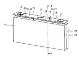
- FIG. 1 is a perspective view of a square secondary battery according to an embodiment of the present disclosure.
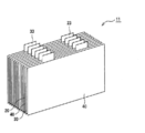
- FIG. 2 is a perspective view of an electrode body and a sealing plate constituting the square secondary battery.
- FIG. 3 is an exploded perspective view of the electrode body of the square secondary battery.
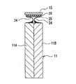
- FIG. 4 is a diagram schematically showing a cross section taken along line AA of FIG.
- FIG. 5 is an enlarged schematic cross-sectional view when a part of the outer side of the first electrode group in the stacking direction is cut by a plane substantially orthogonal to the height direction of the square secondary battery, and a part of the separator and the positive electrode are shown. It is an enlarged schematic cross-sectional view including a part and the adhesive part which is adhering in the adhesive described below.
- FIG. 1 is a perspective view of a square secondary battery according to an embodiment of the present disclosure.
- FIG. 2 is a perspective view of an electrode body and a sealing plate constituting the square secondary battery.
- FIG. 3 is an exploded perspective view
- FIG. 6 is a schematic view showing the relationship between the position in the stacking direction and the adhesive force between the electrode and the separator in the laminated electrode body.
- FIG. 7 is an enlarged schematic cross-sectional view when a part of the inside of the first electrode group in the stacking direction is cut in a plane substantially orthogonal to the height direction, and similarly to FIG. 5, the adhesive exerts adhesive strength. It is an enlarged schematic cross-sectional view which is omitted from the drawing of the part not shown.
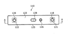
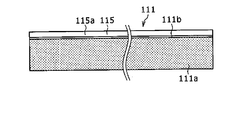
- FIG. 8 is a plan view of the wound type square secondary battery of another embodiment.
- FIG. 10 (b) is a sectional view taken along line BB of FIG. 10 (a)
- FIG. 10 (c) is a sectional view taken along line BB. It is sectional drawing of the CC line of (a).
- FIG. 11A is a plan view of the positive electrode included in the wound square secondary battery.
- FIG. 11B is a plan view of the negative electrode included in the wound square secondary battery.
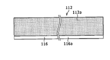
- FIG. 12 is a perspective view showing the winding end end side of the flat wound electrode body included in the wound square secondary battery.
- FIG. 13 is a schematic view corresponding to FIG. 6 in the wound electrode body.
- the description of "numerical value A to numerical value B” means “numerical value A or more and numerical value B or less”.
- the height direction of the outer cans 14 and 140 is defined as the “vertical direction” of the secondary batteries 10 and 110, the sealing plate 15 side and 123 side are “top”, and the bottom side of the outer cans 14 and 140. Is “below”. Further, the direction along the longitudinal direction of the sealing plates 15 and 123 is defined as the "lateral direction" of the secondary batteries 10 and 110.
- the laminated body is composed of, for example, an electrode group or an electrode body, but the first pole is laminated.
- the number is odd, there is only one central first pole in the stacking direction, but when the number of stacked first poles is even, there are two central first poles in the stacking direction. .. Further, there are two first poles of the outermost layer in the stacking direction.
- A1 / A0 When the above A1 / A0 is 0.1 or more, the value of A1 / A0 is the smallest, and the value of A1 / A0 when the first pole of the outermost layer and the first pole in the center in the stacking direction are selected is , 0.1 or more. Similarly, when A1 / A0 is 0.9 or less, A1 when the first pole of the outermost layer and the first pole in the center in the stacking direction, which have the largest value of A1 / A0, are selected. It means that the value of / A0 is 0.9 or less.
- A1 / A0 when the wording that A1 / A0 is a or more is used, it means that the first pole of the outermost layer, which has the smallest value of A1 / A0, and the first pole in the center of the stacking direction are selected. It is assumed that the value of A1 / A0 is equal to or greater than a. Further, when the wording that A1 / A0 is b or less is used, it is when the first pole of the outermost layer and the first pole in the center in the stacking direction, which have the largest value of A1 / A0, are selected. It is assumed that the value of A1 / A0 of is not less than or equal to b.
- the adhesive force at the center of the laminated body (for example, the electrode group or the electrode body) is referred to, when it means the lower limit, the lower one of the one or two first poles at the center is adhered. It will refer to the adhesive force of the first electrode having the force.
- the adhesive strength at the center of the laminated body (for example, the electrode group or the electrode body) is referred to, when it means the upper limit, the higher one of the one or two first poles at the center is adhered. It will refer to the adhesive force of the first electrode having the force.
- FIG. 1 is a perspective view of a square secondary battery 10 according to an embodiment of the present disclosure
- FIG. 2 is a perspective view of an electrode body 11 and a sealing plate 15 constituting the square secondary battery 10 (the outer can 14 is removed). It is a figure which shows the state.
- the square secondary battery (hereinafter, simply referred to as a secondary battery) 10 includes a square container including an outer can 14 and a sealing plate 15 as an outer body, and the outer body includes this. Not limited.
- the secondary battery 10 includes an electrode body 11, an electrolyte, a bottomed tubular outer can 14 in which the electrode body 11 and the electrolyte are housed, a positive electrode terminal 12, and a negative electrode terminal 13. Is attached, and is provided with a sealing plate 15 that closes the opening of the outer can 14.
- the electrode body 11 has a structure in which the positive electrode 20 and the negative electrode 30 are alternately laminated via the separator 40.
- the outer can 14 is a flat, substantially rectangular parallelepiped-shaped metal square container having one end opened in the height direction.
- the outer can 14 and the sealing plate 15 are made of, for example, a metal material containing aluminum as a main component.
- the electrolyte may be an aqueous electrolyte, but is preferably a non-aqueous electrolyte, and in the present embodiment, a non-aqueous electrolyte solution is used.
- the non-aqueous electrolyte solution contains, for example, a non-aqueous solvent and an electrolyte salt dissolved in the non-aqueous solvent.
- the non-aqueous solvent for example, esters, ethers, nitriles, amides, and a mixed solvent of two or more of these may be used.
- the non-aqueous solvent may contain a halogen substituent in which at least a part of hydrogen in these solvents is substituted with a halogen atom such as fluorine.
- the electrolyte salt for example, a lithium salt such as LiPF 6 is used.
- the sealing plate 15 has an elongated rectangular shape, and a positive electrode terminal 12 is arranged on one end side in the longitudinal direction, and a negative electrode terminal 13 is arranged on the other end side in the longitudinal direction of the sealing plate 15.
- the positive electrode terminal 12 and the negative electrode terminal 13 are external connection terminals that are electrically connected to another secondary battery 10 or a load, and are attached to the sealing plate 15 via an insulating member.
- the positive electrode 20 includes a positive electrode tab 23 electrically connected to the positive electrode terminal 12, and the negative electrode 30 includes a negative electrode tab 33 electrically connected to the negative electrode terminal 13.
- the positive electrode terminal 12 is electrically connected to the positive electrode tab group 24 in which a plurality of positive electrode tabs 23 are laminated via the positive electrode current collector plate 25, and the negative electrode terminal 13 is connected to the negative electrode terminal 13 via the negative electrode current collector plate 35.
- the tabs 33 are electrically connected to the negative electrode tab group 34 formed by stacking the tabs 33.
- the sealing plate 15 is provided with a current cutoff device 18 as a functional component for cutting the current path when an abnormality occurs in the battery.
- the functional component is, for example, a component that functions as a safety device or a control device for the secondary battery 10.
- the functional components are arranged close to the positive electrode terminal 12 or the negative electrode terminal 13 on the inner surface of the sealing plate 15.
- the current cutoff device 18 is attached to the positive electrode terminal 12 and is arranged inside the positive electrode terminal 12.
- the current cutoff device 18 is a pressure sensing type safety device that cuts off the current path when an abnormality occurs in the secondary battery 10 and the internal pressure of the outer can 14 rises beyond a predetermined pressure.
- the current cutoff device 18 is arranged, for example, between the positive electrode terminal 12 and the positive electrode current collector plate 25, and is electrically connected to the positive electrode terminal 12 and the positive electrode current collector plate 25 during normal use.
- the structure of the current cutoff device 18 is not particularly limited, but as an example, when the internal pressure rises, it reverses in the direction away from the positive electrode current collector plate 25 to disconnect the electrical connection between the positive electrode current collector plate 25 and the positive electrode terminal 12 and the positive electrode. Examples thereof include an apparatus including an inversion plate that cuts off the current path of the current collector plate 25.
- the sealing plate 15 is provided with a liquid injection unit 16 for injecting a non-aqueous electrolytic solution and a gas discharge valve 17 for opening and discharging gas when an abnormality occurs in the battery.
- the gas discharge valve 17 is arranged at the center of the sealing plate 15 in the longitudinal direction, and the liquid injection part 16 is arranged between the positive electrode terminal 12 and the gas discharge valve 17.
- the electrode body 11 is divided into a first electrode group 11A and a second electrode group 11B.
- the electrode groups 11A and 11B have, for example, the same laminated structure and dimensions, and are arranged in a laminated manner in the thickness direction of the electrode body 11.
- a positive electrode tab group 24 composed of a plurality of positive electrode tabs 23 and a negative electrode tab group 34 composed of a plurality of negative electrode tabs 33 are formed at the upper end of each electrode group, and are connected to each current collector plate of the sealing plate 15.
- the outer peripheral surfaces of the electrode groups 11A and 11B are covered with a separator 40, and the electrode groups 11A and 11B are configured so that independent battery reactions occur.
- FIG. 3 is an exploded perspective view of the electrode body 11.
- the electrode body 11 includes a plurality of positive electrodes 20 and a plurality of negative electrodes 30.
- the electrode groups 11A and 11B constituting the electrode body 11 include, for example, one more negative electrode 30 than the positive electrode 20, and the negative electrodes 30 are arranged on both sides of the electrode groups 11A and 11B in the thickness direction.
- FIG. 3 shows a plurality of separators 40 arranged one by one between the positive electrode 20 and the negative electrode 30, one separator 40 may be included in each of the electrode groups 11A and 11B. In this case, the long separator 40 is folded in ninety-nine and arranged between the positive electrode 20 and the negative electrode 30.
- each of the electrode groups 11A and 11B contains an adhesive and is produced by using a heat pressing step. More specifically, in each of the electrode groups 11A and 11B, a laminated body in which a plurality of positive electrodes 20 and a plurality of negative electrodes 30 are alternately laminated one by one via a separator 40 is laminated using a pair of hot plates. It is produced by applying heat and pressure to the laminate so that at least a part of the adhesive exhibits adhesive strength.
- the electrode body 11 includes an electrode group 11A and an electrode group 11B thus produced, and is a laminated electrode body in which a plurality of positive electrodes 20 and a plurality of negative electrodes 30 are alternately laminated one by one via a separator 40.
- the positive electrode 20 includes a positive electrode tab 23 projecting upward
- the negative electrode 30 includes a negative electrode tab 33 projecting upward.
- the positive electrode 20 and the negative electrode 30 are laminated so that the tabs face the same direction.
- the positive electrode tab 23 is located on one end side in the lateral direction of the electrode body 11
- the negative electrode tab 33 is located on the other end side in the lateral direction of the electrode body 11, and a plurality of positive electrode tabs 23 are arranged in the thickness direction of the electrode body 11.
- a plurality of negative electrode tabs 33 are laminated and arranged so as to be arranged in the thickness direction of the electrode body 11.
- the positive electrode 20 has a positive electrode core body and a positive electrode mixture layer provided on the surface of the positive electrode core body.
- a foil of a metal stable in the potential range of the positive electrode 20 such as aluminum or an aluminum alloy, a film in which the metal is arranged on the surface layer, or the like can be used.
- the positive electrode mixture layer contains a positive electrode active material, a conductive material, and a binder, and is preferably provided on both sides of the positive electrode core body.
- a positive electrode mixture slurry containing a positive electrode active material, a conductive material, a binder, and the like is applied onto the positive electrode core, the coating film is dried, and then compressed to form the positive electrode mixture layer into the positive electrode core. It can be produced by forming it on both sides of the body.
- the positive electrode 20 has a structure in which a positive electrode mixture layer composed of a positive electrode mixture is arranged over the entire surface of the positive electrode core body excluding the positive electrode tab 23 (hereinafter referred to as a “base”).
- the thickness of the positive electrode core is, for example, 5 ⁇ m to 20 ⁇ m, preferably 8 ⁇ m to 15 ⁇ m.
- the base of the positive electrode core has a quadrangular shape in front view, and the positive electrode tab 23 projects from one side of the quadrangle.
- one metal foil is processed to obtain a positive electrode core body in which a base portion and a positive electrode tab 23 are integrally molded.
- Lithium transition metal composite oxide is used as the positive electrode active material.
- Metallic elements contained in the lithium transition metal composite oxide include Ni, Co, Mn, Al, B, Mg, Ti, V, Cr, Fe, Cu, Zn, Ga, Sr, Zr, Nb, In and Sn. , Ta, W and the like. Above all, it is preferable to contain at least one of Ni, Co and Mn.
- suitable composite oxides include lithium transition metal composite oxides containing Ni, Co and Mn, and lithium transition metal composite oxides containing Ni, Co and Al.
- Examples of the conductive material contained in the positive electrode mixture layer include carbon materials such as carbon black, acetylene black, ketjen black, and graphite.
- Examples of the binder contained in the positive electrode mixture layer include fluororesins such as polytetrafluoroethylene (PTFE) and polyvinylidene fluoride (PVdF), polyacrylonitrile (PAN), polyimide resins, acrylic resins, and polyolefin resins. .. Further, these resins may be used in combination with a cellulose derivative such as carboxymethyl cellulose (CMC) or a salt thereof, polyethylene oxide (PEO), or the like.
- CMC carboxymethyl cellulose
- PEO polyethylene oxide
- the negative electrode 30 has a negative electrode core body and a negative electrode mixture layer provided on the surface of the negative electrode core body and composed of a negative electrode mixture.
- a metal foil such as copper that is stable in the potential range of the negative electrode 30, a film on which the metal is arranged on the surface layer, or the like can be used.
- the negative electrode mixture layer contains a negative electrode active material and a binder, and is preferably provided on both sides of the negative electrode core body.
- a negative electrode mixture slurry containing a negative electrode active material, a binder, and the like is applied to the surface of the negative electrode core, the coating film is dried, and then compressed to form a negative electrode mixture layer of the negative electrode core. It can be produced by forming it on both sides.
- the negative electrode 30 has a structure in which a negative electrode mixture layer is formed on the entire surface of the negative electrode core body except for the negative electrode tab 33.
- the thickness of the negative electrode core is, for example, 3 ⁇ m to 15 ⁇ m, preferably 5 ⁇ m to 10 ⁇ m.
- the base of the negative electrode core has a quadrangular shape in front view, and the negative electrode tab 33 projects from one side of the quadrangle.
- one metal foil is processed to obtain a negative electrode core body in which a base portion and a negative electrode tab 33 are integrally molded.
- the negative electrode active material for example, a carbon-based active material that reversibly occludes and releases lithium ions is used.
- Suitable carbon-based active materials are natural graphite such as scaly graphite, massive graphite, earthy graphite, and graphite such as artificial graphite such as massive artificial graphite (MAG) and graphitized mesophase carbon microbeads (MCMB).
- a Si-based active material composed of at least one of Si and a Si-containing compound may be used, or a carbon-based active material and a Si-based active material may be used in combination.
- the binder contained in the negative electrode mixture layer fluororesin, PAN, polyimide, acrylic resin, polyolefin or the like can be used as in the case of the positive electrode 20, but styrene-butadiene rubber (SBR) is used. Is preferable.
- the negative electrode mixture layer preferably further contains CMC or a salt thereof, polyacrylic acid (PAA) or a salt thereof, polyvinyl alcohol (PVA) and the like. Above all, it is preferable to use SBR in combination with CMC or a salt thereof, PAA or a salt thereof.
- FIG. 4 is a diagram schematically showing a cross section taken along line AA of FIG.
- the electrode body 11 has a positive electrode tab group 24 in which a plurality of positive electrode tabs 23 are laminated, and a negative electrode tab group 34 in which a plurality of negative electrode tabs 33 are laminated.
- the positive electrode tab group 24 is formed by superimposing a plurality of positive electrode tabs 23 in the stacking direction of the electrodes, one for each of the electrode groups 11A and 11B.
- the negative electrode tab group 34 is formed by superimposing a plurality of negative electrode tabs 33 in the stacking direction of the electrodes, one for each of the electrode groups 11A and 11B.
- the positive electrode tab group 24 is joined to the positive electrode current collector plate 25 attached to the inner surface (lower surface) of the sealing plate 15 by welding or the like.
- the positive electrode current collector plate 25 is a plate-shaped conductive member that is electrically connected to the positive electrode terminal 12 via the current cutoff device 18.
- An insulating member 26 is interposed between the sealing plate 15 and the positive electrode current collector plate 25 to prevent contact between the two members.
- the negative electrode tab group 34 is joined to the negative electrode current collector plate 35 attached to the inner surface of the sealing plate 15 via an insulating member by welding or the like.
- the shapes of the positive electrode tab group 24 and the negative electrode tab group 34 are not particularly limited as long as they function as conductive paths connecting the electrode body 11 and each terminal.
- the plurality of positive electrode tabs 23 and the plurality of negative electrode tabs 33 of the electrode group 11A are laminated in a state of being curved from the outside to the inside of the secondary battery 10, respectively, and the cross-sectional view is substantially U.
- a character-shaped positive electrode tab group 24 and a negative electrode tab group 34 are formed.
- the electrode group 11B also has a tab group having a substantially U-shaped cross section. Each tab group may have a U-shape curved from the inside to the outside of the secondary battery 10. Then, as shown in FIG.
- the cross-sectional shape of the tab group of the other electrode group is approximately the boundary line of the electrode group with respect to the cross-sectional shape of the tab group of one electrode group. They may be arranged symmetrically.
- the positive electrode tab group 24 may be welded to the upper surface of the positive electrode current collector plate 25 facing the sealing plate 15 side, but is preferably welded to the lower surface of the positive electrode current collector plate 25. In the present embodiment, both the positive electrode tab group 24 and the negative electrode tab group 34 are welded to the lower surface of the current collector plate. For example, the positive electrode tab group 24 is welded to the lower surface of the positive electrode current collector plate 25 and the negative electrode tabs. Group 34 may be welded to the upper surface of the negative electrode current collector plate 35. Further, in the present embodiment, the case where the electrode body 11 includes the divided first electrode group 11A and the second electrode group 11B has been described, but the electrode body has one undivided electrode group. You may.
- the sealing plate 15 After welding the electrode body 11 to the sealing plate 15, for example, the sealing plate 15 is fitted into the opening of the outer can 14, and the sealing plate 15 to which the electrode body 11 is attached and the outer can 14 are fitted. Laser weld the joint. After that, the non-aqueous electrolytic solution is injected into the outer can 14 using the liquid injection unit 16, and then the liquid injection unit 16 is sealed with a blind rivet to form the secondary battery 10.
- FIG. 5 is an enlarged schematic cross-sectional view of the first electrode group 11A (hereinafter, simply referred to as the electrode group 11A) when a part of the outside in the stacking direction is cut along a plane substantially orthogonal to the height direction. It is an enlarged schematic cross-sectional view including a part of 40, a part of a positive electrode 20, and an adhesive portion (a portion exhibiting adhesive force in the adhesive) 50a that is adhered in the adhesive 50 described below. Paradoxically, FIG. 5 is an enlarged schematic cross-sectional view of the adhesive 50 in which the portion that does not contribute to adhesion is omitted.
- the separator 40 has a resin base material (for example, a polyolefin base material) 40a and a heat-resistant layer provided on one side surface of the base material 40a in the thickness direction by an existing method such as coating. It has 40b.
- the heat-resistant layer 40b may be provided on both one side surface and the other side surface in the thickness direction of the base material 40a, or the separator 40 may not have a heat-resistant layer at all.
- the electrode group 11A further includes an adhesive 50.
- the adhesive 50 is provided with the heat-resistant layer 40b on the entire surface of one side surface of the base material 40a in the thickness direction, and then the entire surface of one side surface of the separator 40 on which the heat-resistant layer 40b is not provided. And, it is applied by arranging a plurality of dot-shaped adhesives (dot-shaped portions) by printing or the like so that the area density is substantially constant over the entire area of the other side surface of the separator 40 provided with the heat-resistant layer 40b. ..
- the amount of each dot-shaped adhesive 50 is substantially the same.
- the number density of the dot-shaped adhesive 50 is substantially constant over the entire area of one side surface and the entire area of the other side surface of the separator 40.
- the coating form of the adhesive 50 may not be a dot-shaped coating form, but may be a coating form on the entire surface of the separator. That is, the adhesive may be applied to at least one of one side surface and the other side surface of the separator so that the area density is substantially constant, and an adhesive layer may be provided on at least one side surface of the separator.
- the adhesive 50 is located between the base material 40a and the electrode (at least one of the positive electrode 20 and the negative electrode 30), and the adhesive 50 is placed on the base material 40a.
- a heat-resistant layer (slurry coating layer) 40b containing alumina particles as a main component may be provided, and the adhesive 50 may be coated on the heat-resistant layer (slurry coating layer) 40b.
- the resin-made porous base material 40a functions as a separator 40 by itself.
- a porous film having ion permeability and insulating property is used as the base material 40a.
- the thickness of the base material 40a is, for example, 1 ⁇ m to 20 ⁇ m.
- the material of the base material 40a include olefin resins such as polyethylene, polypropylene, a copolymer of ethylene-propylene, ethylene, propylene, and a copolymer with other ⁇ -olefins.
- the melting point of the resin base material is generally 200 ° C. or lower.
- the porous film constituting the base material 40a has many pores for allowing lithium ions to permeate, but the unevenness of the surface thereof is smaller than the surface unevenness of the heat-resistant layer 40b, and the surface is flatter than that of the heat-resistant layer 40b. is there.
- the size (maximum length) of the holes or recesses existing on the surface of the base material 40a is, for example, less than 0.5 ⁇ m, preferably less than 0.3 ⁇ m.
- the porous heat-resistant layer 40b may be composed of a resin having a higher melting point or softening point than the resin constituting the base material 40a, for example, aramid resin, polyimide, polyamide-imide, etc., but preferably an inorganic compound as a main component. It is composed.
- the heat-resistant layer 40b is preferably composed of insulating inorganic compound particles and a binder that binds the particles to each other and the particles and the base material 40a.
- the heat-resistant layer 40b has ion permeability and insulating property like the base material 40a.
- the thickness of the heat-resistant layer 40b is, for example, 1 ⁇ m to 10 ⁇ m, preferably 1 ⁇ m to 6 ⁇ m.
- the inorganic compound particles that are the main component of the heat-resistant layer 40b at least one selected from, for example, alumina, boehmite, silica, titania, and zirconia can be used. Above all, it is preferable to use alumina or boehmite.
- the content of the inorganic compound particles is preferably 85% by mass to 99.9% by mass, more preferably 90% by mass to 99.5% by mass, based on the mass of the heat-resistant layer 42.
- the shape of the inorganic compound particles is not particularly limited, and for example, spherical or square columnar particles can be used.
- the average particle size of the spherical particles or the average length of one side of the square columnar particles is preferably 0.1 ⁇ m to 1.5 ⁇ m, more preferably 0.5 ⁇ m to 1.2 ⁇ m.
- the heat-resistant layer 40b having good ion permeability and excellent durability can be formed.
- the binder constituting the heat-resistant layer 40b for example, a fluororesin such as PVdF, SBR, or the like, which is the same as the binder contained in the positive electrode mixture layer and the negative electrode mixture layer, can be used.
- the content of the binder is preferably 0.1% by mass to 15% by mass, more preferably 0.5% by mass to 10% by mass, based on the mass of the heat-resistant layer 40b.
- the heat-resistant layer 40b is formed by applying, for example, a slurry containing inorganic compound particles and a binder to one side surface of a porous film constituting the base material 40a, and drying the coating film. By forming the heat-resistant layer 40b on the base material 40a as described above, grooves and recesses are formed on the surface of the heat-resistant layer 40b between the heat-resistant layer 40b and the adjacent inorganic compound particles.
- the adhesive 50 for example, an acrylic resin adhesive, a urethane resin adhesive, an ethylene-vinyl acetate resin adhesive, an epoxy resin adhesive, or the like can be used.
- the resin constituting the adhesive 50 include fluorine-based resins such as an acrylic polymer, a diene polymer, polyurethane, and PVdF.
- the shape of the adhesive 50 may be a particulate polymer or a layered shape. The adhesive 50 may be applied to either one side or both sides of the separator 40, but the fact that the adhesive 50 is applied to both sides enhances the convenience of handling the electrode group 11A (electrode body 11). Moreover, it is preferable because the displacement of the laminated body can be suppressed.
- the base material 40a is made of a polyethylene porous film
- a heat-resistant layer 40b is formed on one side of the base material 40a
- the base material 40a forms one side surface of the separator 40.
- Adhesive particles made of an acrylic polymer may be arranged in dots on both the heat-resistant layer 40b forming the other side surface of the separator 40. Then, the heat-resistant layer 40b and the positive electrode mixture layer may be adhered with adhesive particles, and the base material 40a and the negative electrode mixture layer may be adhered with adhesive particles.
- Adhesion between each of the mixture layers and the separator 40 is performed, for example, in a hot pressing step in which a press plate warmed to a predetermined temperature is brought into contact with one side and the other side of the laminated body in the laminating direction and pressure is applied. Will be done.
- the laminated electrode group 11A may be formed between the separator 40 and the electrodes 20 and 30, respectively, and may include an adhesive layer composed of adhesive particles.
- the thickness of the adhesive layer is, for example, 0.1 ⁇ m to 1 ⁇ m or 0.2 ⁇ m to 0.9 ⁇ m, and is determined by the amount of the adhesive and the particle size of the adhesive when it is in the form of particles.
- the adhesive layer is formed by, for example, applying a slurry containing adhesive particles to the surface of a separator and drying it.
- a so-called emulsion in which fine adhesive particles are dispersed in water can be used. In this case, it is possible to form a separator with an adhesive layer in which an adhesive layer made of adhesive particles is formed on both sides.
- the average particle size of the adhesive particles is, for example, 0.1 ⁇ m to 1 ⁇ m, preferably 0.5 ⁇ m to 0.7 ⁇ m.
- the average particle size of the adhesive particles is measured by observing the surface of the separator using SEM in the same manner as the average particle size of the inorganic compound particles constituting the heat-resistant layer.
- the average particle size of the adhesive particles is, for example, equal to or smaller than the average particle size of the inorganic compound particles constituting the heat-resistant layer. Therefore, the adhesive particles may completely enter the recesses existing on the surface of the heat-resistant layer.
- the average particle size of the adhesive particles is larger than, for example, the grooves or recesses existing on the surface of the resin base material. Therefore, the adhesive surface is wider than that of the heat-resistant layer, and the minimum necessary adhesive force can be easily obtained.
- a bonding method using a hot press can be used as a method for adhering the separator and the electrode.
- any method other than the heat pressing method may be adopted.
- the bonding method using a hot press for example, a method in which the laminate is placed on a metal plate heated to a predetermined temperature and then the metal plate heated to a predetermined temperature is pressed from above the laminate at a constant pressure is preferable. ..
- the temperatures of the upper and lower metal plates may be the same or different, so that the temperature of the metal plates is equal to or higher than the softening temperature of the adhesive, and the time for heat transfer to the central part of the laminate can be shortened.
- a higher temperature is preferable, but if it is too high, the heat shrinkage of the separator becomes remarkable. Therefore, 50 ° C. or higher and 120 ° C. or lower is preferable, and 70 ° C. or higher and 110 ° C. or lower is more preferable.
- the press pressure is preferably 0.5 MPa or more and 8 MPa or less, more preferably 1 MPa or more and 4 MPa or less.
- the time for pressing the laminate is short in order to accelerate the production tact, but if it is too short, the adhesive force at the center of the electrode group (electrode body) tends to be insufficient.
- the thickness of the electrodes (electrode plates) increases and the number of layers increases, it becomes more difficult for heat to be transferred to the inside of the electrode group (inside the electrode body). It takes a lot of time.
- an active material material containing graphite as a main component may be formed on both sides of the Cu core material with the same film thickness on both sides, and a electrode plate having a total thickness of 165 ⁇ m may be used.
- an active material material containing lithium nickel-cobalt-manganese composite oxide as a main component may be formed on both sides of the Al core material with the same film thickness on both sides, and an electrode plate having a total thickness of 137 ⁇ m may be used.
- an electrode body having 36 negative electrodes and 35 positive electrodes can be used, but the present invention is not limited to this.
- the electrode body 11 is inserted into a metal outer can 14, covered with a sealing body, and then the electrolytic solution is injected from the sealing port.
- the electrolytic solution begins to permeate from the end between the electrodes 20 and 30, and the liquid permeates to the central portion of the electrode groups 11A and 11B.
- One side surface (upper surface) of the electrode groups 11A and 11B in the stacking direction and the other side surface (lower surface) of the electrode groups 11A and 11B in the stacking direction have fewer electrode ends that rotate around the electrode, so that the amount of permeated liquid is abundant.
- the amount of penetrant tends to be lacking toward the center of the electrode groups 11A and 11B in the stacking direction.
- the liquid circulation property of the electrolytic solution becomes worse toward the central portion of the electrode groups 11A and 11B in the stacking direction, and it takes time for the electrolytic solution to permeate the entire electrode groups 11A and 11B. For this reason, it is preferable for the liquid circulation property that the adhesive force at the central portion of each of the electrode groups 11A and 11B in the stacking direction is weakened to the minimum necessary so as to increase the gap through which the electrolytic solution permeates.
- the adhesive force at the center of the electrode groups 11A and 11B in the stacking direction is the adhesion between one side surface in the stacking direction and the other side surface in the stacking direction. It is 0.1 times or more, more preferably 0.3 times or more with respect to any of the forces. Further, with respect to each of the electrode groups 11A and 11B, the adhesive force at the center of the electrode groups 11A and 11B in the stacking direction is applied to both one side surface of the electrode groups 11A and 11B in the stacking direction and the other side surface in the stacking direction. It is 0.9 times or less, more preferably 0.5 times or less.
- the adhesive force at the center of the electrode groups 11A and 11B in the stacking direction is the adhesion of at least one of the adhesive force of one side surface of the electrode groups 11A and 11B in the stacking direction and the other side surface in the stacking direction. If it is less than 0.1 times the force, the central portion of the electrode body in the stacking direction may be peeled off when the electrode body after bonding is conveyed.
- the adhesive force at the center of the electrode groups 11A and 11B in the stacking direction is the adhesion of at least one of the adhesive force of one side surface of the electrode groups 11A and 11B in the stacking direction and the other side surface in the stacking direction. If it is larger than 0.9 times the force, it is necessary to sufficiently melt the adhesive in the central portion in the laminating direction, which requires a large amount of time for hot pressing and deteriorates productivity.
- the separator outside the stacking direction is likely to be crushed, so the temperature and pressure must be smaller than the predetermined values, and as a result, the temperature and pressure must be lower than the predetermined values, which is 0.9 times. It will take a lot of time for the hot press to realize. Further, the adhesive force after the electrolytic solution is injected after hot pressing and the liquid is sufficiently rotated tends to be lower than the adhesive force before the liquid is rotated, but the ratio of the adhesive force is generally maintained.
- the amount of liquid that has permeated into the electrode active material can be determined, for example, by changing the mass of the electrode before and after injection of the electrolytic solution.
- a separator containing a porous resin base material and a porous heat-resistant layer formed only on one surface of the resin base material was prepared.
- the resin base material a polyethylene porous film having a thickness of 15 ⁇ m was used.
- the heat-resistant layer a layer mainly composed of square columnar boehmite particles having an average length of 0.5 ⁇ m on each side was used. On the surface of this layer, a large number of grooves and recesses having a size that allows adhesive particles having a particle size of about 0.5 ⁇ m to enter without being significantly deformed were observed.
- Ethylene carbonate (EC), ethyl methyl carbonate (EMC), and dimethyl carbonate (DMC) were mixed in a volume ratio of 3: 3: 4.
- An electrolytic solution was prepared by dissolving LiPF 6 in the mixed solvent at a concentration of 1.2 mol / L.
- Electrode body A plurality of dot-shaped adhesives having a constant area density were applied by printing on both one side surface and the other side surface in the thickness direction of the separator prepared as described above. Specifically, a dispersion (emulsion) of adhesive particles composed mainly of an acrylic polymer was applied to both sides of the prepared separator (long body) and dried to prepare a separator with an adhesive. Then, a separator is placed in the lowermost layer, a negative electrode plate with an electrode tab on which no active material is applied, a positive electrode plate with a tab on the positive electrode plate with a tab, and a positive electrode plate with a tab on the negative electrode plate with a folded material. It was covered with a folded separator, and ...
- the negative electrode plate and the positive electrode plate were laminated while folding the separator in a zigzag manner.
- the separator was further placed on the negative electrode plate, and at the same time, the laminate was wound around one and a half turns with the separator, and then the separator end was taped.
- the laminate was placed on a preheated press plate, and pressure was applied to the laminate by the similarly heated upper press plate. Five seconds after the laminate was placed on the lower press plate, the upper press plate was lowered to apply pressure to the laminate. After the pressure was applied completely, the laminate was conveyed from the press.
- the outer can a square outer can containing Al as a main component, having a height of 95 mm, a length of 148 mm in the lateral direction, a length of 29 mm in the depth direction, and a thickness of 1.5 mm was used.
- a secondary battery was formed by injecting a non-aqueous electrolytic solution into the outer can using the liquid injection unit 16 and then sealing the liquid injection unit with a blind rivet.
- ⁇ Calculation of adhesive force ratio In the evaluation of the adhesive force ratio, the adhesive force between the positive electrode and the separator of the outermost layer and the adhesive force between the negative electrode and the separator are measured, respectively, and the adhesive force between the electrode plate and the separator showing the higher value is measured. , The value is set to A0, and the 9th adhesive force is counted from the upper and lower negative electrode plates or the upper and lower positive electrode plates of the electrode body, and the 18th sheet is counted from the upper and lower negative electrode plates or the upper and lower positive electrode plates. The adhesive strength of (the central layer of the electrode body) was measured, and the ratios A9 / A0 and A18 / A0 when the adhesive strength was A9 and A18, respectively, were determined.
- the adhesive strength between the porous film and the negative electrode mixture layer is high in all the examples and the comparative examples, and the value of Ai / A0 determines the adhesive force between the porous film and the negative electrode mixture layer. used. Further, since the adhesive strength of the upper and lower plates did not change, the adhesive strength of the lower plate was set to A0. The adhesive strength was evaluated both before and after the electrolytic solution was contained in the electrode body.
- the adhesive strength between the separator and each electrode was measured as follows. That is, for each test sample (each test cell), a device in which a digital force gauge (manufactured by Nippon Densan Symposium Co., Ltd., FGS-TV) is attached to a small desktop tester (manufactured by Nippon Densan Symposium Co., Ltd., FGS-TV) is attached.
- a digital force gauge manufactured by Nippon Densan Symposium Co., Ltd., FGS-TV
- a small desktop tester manufactured by Nippon Densan Symposium Co., Ltd., FGS-TV
- the test cell before injection of the electrolytic solution was disassembled leaving a joint surface for measuring the adhesive strength, and the disassembled test piece was cut into strips with a width of 20 mm.
- the surface of the strip-shaped test piece opposite to the joint surface to be measured was attached to a flat plate using double-sided tape.
- the flat plate was installed on a jig constrained to move in the plate surface direction without resistance without moving in the vertical direction.
- the end of the separator of the test piece was picked with a clip attached to the tip of the digital force gauge and pulled up in the direction of 90 ° with respect to the electrode surface, and the force applied to the digital force gauge at this time was measured.
- the adhesive strength was measured both before and after the electrolytic solution was contained in the electrode body, using the electrode body before and after the electrolytic solution permeated.
- Test results The test results are shown in Table 1 below.
- the adhesive force ratio is 0.1 or more and 0.9 or less before and after the electrolytic solution is contained in the electrode, the productivity and the liquid We were able to produce an electrode body with excellent rotation (liquid permeability). Furthermore, according to the above-mentioned one test example, when the adhesive force ratio is 0.4 or less before and after the electrolytic solution is contained in the electrode, the electrode body is excellent in both productivity and liquid circulation. Was able to be produced. According to a plurality of tests conducted by the inventor of the present application in which the temperature condition of the hot plate in the pressing process, the pressure condition applied by the hot plate, and the pressing time of the hot plate are changed, the adhesive force ratio is 0.1 or more. If it is 0.9 or less, an electrode body having good productivity and liquid circulation can be produced, and if the adhesive force ratio is 0.3 or more and 0.5 or less, the productivity and liquid circulation are good. It was confirmed that an electrode body excellent in both could be produced.
- the secondary battery 10 of the present disclosure includes an adhesive 50 arranged between at least one side surface of the separator 40 in the thickness direction and the negative electrode (first electrode) 30. Further, in the secondary battery 10 of the present disclosure, the adhesive force between the negative electrode 30 of the outermost layer and the separator 40 is set to A0 [N / m], and the negative electrode 30 and the separator located at the center in the stacking direction in the laminated group (laminated body) 11A. When the adhesive strength of 40 is A1 [N / m], A1 / A0 is 0.1 or more and less than 0.9.
- the electrolytic solution can be permeated to the inside in the stacking direction in a short time. Therefore, the secondary battery 10 can be manufactured in a short time so that the holding amount of the electrolytic solution can be easily made uniform regardless of the existing position in the stacking direction. Therefore, not only can the power generation performance of the secondary battery 10 be improved, but also the occurrence of a reaction rate difference at the existing position in the stacking direction can be suppressed, and as a result, the durability of the secondary battery 10 can be improved, and further, the secondary battery 10 can be improved. The productivity of the next battery can also be improved.
- the long side of the negative electrode 30 may be 10 cm or more, and the area of one side surface of the negative electrode 30 in the thickness direction may be 90 cm 2 or more.
- the liquid circulation property (liquid permeability) to the central portion in the stacking direction of the electrolytic solution becomes lower as the capacity of the secondary battery 10 becomes larger.
- the secondary battery 10 is a large-capacity battery in which the long side of the negative electrode 30 is 10 cm or more and the area of one side surface of the negative electrode 30 in the thickness direction is 90 cm 2 or more. Therefore, thanks to the excellent liquid circulation of the electrolytic solution, which is one of the main effects of the technology of the present disclosure, the secondary battery is compared with the secondary battery of the conventional configuration using an adhesive. The power generation performance and durability of the 10 can be improved to each stage.
- a second adhesive arranged between the other side surface of the separator 40 in the thickness direction and the positive electrode 20 may be provided. Further, when the adhesive force between the positive electrode 20 and the separator 40 of the outermost layer is A2 [N / m] and the adhesive force between the positive electrode 20 and the separator 40 located at the center in the stacking direction in the laminated body is A3 [N / m]. , A3 / A2 may be 0.1 or more and less than 0.9.
- the electrolytic solution easily permeates into the central portion of the electrode group 11A in the stacking direction also between the positive electrode 20 and the separator 40. Therefore, the power generation performance, durability, and mass productivity of the secondary battery 10 can be further improved.
- one side surface of the separator 40 to which the adhesive is applied may be contained in a porous base material having ion permeability and insulating property (for example, a polyolefin base material).
- the adhesive force acting between the separator 40 and the electrode (at least one of the positive electrode and the negative electrode) can be increased, and the displacement of the separator 40 with respect to the electrode can be greatly suppressed.
- a porous base material having ion permeability and insulating property for example, a polyolefin base material. Good.
- the adhesive force acting between the separator 40 and the positive electrode 20 can be increased, and the adhesive force acting between the separator 40 and the negative electrode 30 can also be increased.
- the adhesive is applied to at least one side surface of the separator 40 in the thickness direction so that the area density is substantially constant, and the area density of the bonded portion of the adhesive may vary in the stacking direction. ..
- FIG. 6 is a schematic view showing the relationship between the position in the stacking direction (indicated by the arrow A) and the adhesive force between the electrode and the separator in the laminated electrode body.
- FIG. 6C in the technique of the present disclosure, in a two-dimensional graph in which the position in the stacking direction is the vertical axis and the adhesive force is the horizontal axis, the distribution of the adhesive force between the electrode and the separator is in the stacking direction.
- the function f is close to line symmetry so that both end portions are large and have a minimum value in the central portion in the stacking direction.
- such a function is applied from the hot plate to the laminate in the press process in a two-dimensional graph in which the position in the stacking direction is on the vertical axis and the amount of heat applied from the hot plate to the laminate in the press process is on the horizontal axis. It behaves similarly to a function that indicates the distribution of heat (temperature distribution). That is, the distribution (temperature distribution) of the amount of heat applied from the hot plate to the laminated body in the pressing process is also a minimum value in the central portion in the laminated direction because both end portions in the lamination direction are large as shown in FIG. 6 (c). It becomes a function close to line symmetry such that has.
- the adhesive force on the inner side (center side) in the stacking direction can be easily applied to the adhesive force on the outer side in the stacking direction. Can be made smaller. That is, according to this modification, the adhesive is applied to at least one side surface of the separator in the thickness direction so that the area density is substantially constant, but the tendency similar to the function shown by f in FIG. 6 (c) is observed. Also in the heat pressing process shown, the amount of heat distribution (temperature distribution) is used to make the amount that melts in the adhesive inside the stacking direction smaller than the amount that melts in the adhesive outside the stacking direction, and the adhesion inside the stacking direction. The amount of the adhesive portion that develops the adhesive force in the agent is made smaller than the amount of the adhesive portion that develops the adhesive force in the adhesive outside in the stacking direction.
- FIG. 7 is an enlarged schematic cross-sectional view when a part of the inside of the first electrode group 11A in the stacking direction is cut by a plane substantially orthogonal to the height direction, and the adhesive is applied as in FIG.
- the illustration of the portion where the adhesive force is not exhibited in 50 is an enlarged schematic cross-sectional view which is omitted.
- the area density of the adhesive 50 to be applied is the same both on the outside and the inside in the stacking direction, but as shown in FIGS. 5 and 7, the tendency similar to the function shown by f in FIG. 6 (c) is observed.
- the amount of the adhesive portions 50a and 50b that develop adhesive force in the adhesive 50 can be made smaller on the inner side in the stacking direction than on the outer side in the stacking direction. Therefore, the adhesive force on the inner side (center side) in the stacking direction can be easily reduced with respect to the adhesive force on the outer side in the stacking direction.
- the electrode body may be manufactured by using a plurality of different separators.
- the separator may be folded in a zigzag.
- the handleability of the laminated body (electrode group, electrode body) can be improved.
- the laminated electrode body 11 is manufactured by welding at least a part of the adhesive 50 in a hot pressing step. It may be. According to this configuration, the secondary battery 10 having the laminated electrode body 11 of the present disclosure can be easily manufactured.
- FIG. 8 is a plan view of the wound type square secondary battery 110
- FIG. 9 is a front view of the square secondary battery 110.
- 10 (a) is a sectional view taken along line AA of FIG. 8
- FIG. 10 (b) is a sectional view taken along line BB of FIG. 10 (a)
- FIG. 10 (c) is a sectional view taken along line BB.
- FIG. 10 (a) is a cross-sectional view taken along the line CC of FIG. 10 (a).
- 11A is a plan view of the positive electrode included in the square secondary battery 110, and FIG.
- FIG. 11B is a plan view of the negative electrode included in the square secondary battery 110.
- FIG. 12 is a perspective view showing the winding end end side of the flat wound electrode body included in the square secondary battery 110.
- the material of each member of the wound type square secondary battery 110 the same material as the material of the corresponding member of the above-mentioned laminated type square secondary battery 10 can be used. Therefore, in the following description, the material of each member will be briefly described or the description will be omitted.
- the square secondary battery 110 includes an outer can (square outer can) 125 (see FIGS. 8 to 10) and a sealing plate. It includes 123 (see FIG. 8) and a flat wound electrode body 114 (see FIGS. 9A and 12).
- the outer can 125 is made of, for example, aluminum or an aluminum alloy, and has an opening on one side in the height direction. As shown in FIG. 9, the outer can 125 has a bottom 140, a pair of first side surfaces 141, and a pair of second side surfaces 142, and the second side surface 142 is larger than the first side surface 141. As shown in FIG.
- the sealing plate 123 is fitted into the opening of the outer can 125.
- a square battery case 145 is formed by joining the fitting portion between the sealing plate 123 and the outer can 125.
- the material of each member in the wound type secondary battery 110 the same material as the material of the corresponding member in the laminated type square secondary battery 10 can be adopted. Therefore, in the following description of the winding type secondary battery 110, the material of each member will be briefly described or the description will be omitted.
- the wound electrode body 114 has a structure in which the positive electrode 111 and the negative electrode 112 are wound in a state of being insulated from each other via the separator 113.
- the outermost surface side of the wound electrode body 114 is covered with the separator 113, and the negative electrode 112 is arranged on the outer peripheral side of the positive electrode 111.
- the positive electrode 111 is determined by applying a positive electrode mixture slurry on both sides of a strip-shaped positive electrode core 115 made of aluminum or an aluminum alloy foil having a thickness of about 10 to 20 ⁇ m, drying and compressing the slurry. Cut into strips to the dimensions.
- the positive electrode mixture slurry contains a positive electrode active material, a conductive agent, a binder and the like. At this time, a positive electrode core body exposed portion 115a in which the positive electrode mixture layer 111a is not formed on both sides along the longitudinal direction is formed at one end in the width direction.
- a positive electrode protective layer 111b is formed on the surface of at least one side of the positive electrode core body exposed portion 115a along the length direction of the positive electrode core body exposed portion 115a so as to be adjacent to, for example, the positive electrode mixture layer 111a. Is preferable.
- the positive electrode protective layer 111b contains insulating inorganic particles and a binder.
- the positive electrode protective layer 111b has lower conductivity than the positive electrode mixture layer 111a.
- the positive electrode protective layer 111b By providing the positive electrode protective layer 111b, it is possible to prevent a short circuit between the negative electrode mixture layer 112a and the positive electrode core 115 due to foreign matter or the like. Further, the positive electrode protective layer 111b can contain conductive inorganic particles. The positive electrode protective layer 111b may not be provided.
- the negative electrode 112 is formed by applying a negative electrode mixture slurry to both surfaces of a strip-shaped negative electrode core 116 made of copper or a copper alloy foil having a thickness of about 5 to 15 ⁇ m, drying and compressing the negative electrode 112. , Cut into strips to the specified dimensions.
- the negative electrode mixture slurry contains a negative electrode active material, a binder and the like.
- the negative electrode core body exposed portion 116a in which the negative electrode mixture layer 112a is not formed on both sides along the longitudinal direction is formed.
- the positive electrode core body exposed portion 115a to the negative electrode core body exposed portion 116a may be formed along the ends on both sides of the positive electrode 111 to the negative electrode 112 in the width direction, respectively.
- the positive electrode 111 and the negative electrode 112 do not overlap the positive electrode core body exposed portion 115a and the negative electrode mixture layer 112a, and the negative electrode core body exposed portion 116a and the positive electrode mixture layer 111a do not overlap.
- the positive electrode 111 and the negative electrode 112 are wound so as to be insulated from each other with the separator 113 coated with the adhesive having a substantially constant area density on at least one side surface in the thickness direction.
- the formed wound body is sandwiched between a pair of hot plates and formed into a flat shape to produce a flat wound electrode body 114.
- a plurality of winding electrode bodies 114 are provided at one end in the direction in which the winding axis extends (corresponding to the width direction when the band-shaped positive electrode 111, the band-shaped negative electrode 112, and the band-shaped separator 113 are developed in a rectangular shape).
- a laminated positive electrode core body exposed portion 115a is provided, and a plurality of laminated negative electrode core body exposed portions 116a are provided at the other end portion.
- a porous polyolefin film can be preferably used as the separator 113. It is preferable that the width of the separator 113 can cover the positive electrode mixture layer 111a and the positive electrode protective layer 111b and is larger than the width of the negative electrode mixture layer 112a.
- the exposed positive electrode core body 115a in which a plurality of sheets are laminated is electrically connected to the positive electrode terminal 118 via the positive electrode current collector 117 (see FIG. 10A), and the plurality of sheets are laminated.
- the negative electrode core body exposed portion 116a is electrically connected to the negative electrode terminal 120 via the negative electrode current collector 119 (see FIG. 10A).
- an operation is performed between the positive electrode current collector 117 and the positive electrode terminal 118 when the gas pressure inside the battery case 145 exceeds a predetermined value. It is preferable that the current cutoff mechanism 127 is provided.
- the positive electrode terminal 118 and the negative electrode terminal 120 are fixed to the sealing plate 123 via the insulating members 121 and 122, respectively.
- the sealing plate 123 has a gas discharge valve 128 that is opened when the gas pressure in the battery case 145 becomes higher than the operating pressure of the current cutoff mechanism 127.
- the positive electrode current collector 117, the positive electrode terminal 118, and the sealing plate 123 are each made of aluminum or an aluminum alloy, and the negative electrode current collector 119 and the negative electrode terminal 120 are each made of copper or a copper alloy. As shown in FIG.
- the flat wound electrode body 114 has an exterior in which one surface is open with an insulating insulating sheet (resin sheet) 124 interposed around the periphery except for the sealing plate 123 side. It is inserted into the can 125.
- an insulating insulating sheet (resin sheet) 124 interposed around the periphery except for the sealing plate 123 side. It is inserted into the can 125.
- the plurality of positive electrode core body exposed portions 115a wound and laminated are converged to the central portion in the thickness direction and further 2 It is divided, the positive electrode core body exposed portion 115a is converged, and the positive electrode intermediate member 130 is arranged between them.
- the positive electrode intermediate member 130 is made of a resin material, and the positive electrode intermediate member 130 holds one or more, for example, two conductive positive electrode conductive members 129.
- the positive electrode conductive member 129 for example, a columnar one is used, and truncated cone-shaped protrusions acting as projections are formed on both ends facing the laminated positive electrode core body exposed portions 115a.
- the plurality of negative electrode core body exposed portions 116a that are wound and laminated are converged to the center side in the thickness direction and further divided into two, and the negative electrode core body exposed portion 116a is converged during that time.
- An intermediate member 132 is arranged.
- the negative electrode intermediate member 132 is made of a resin material, and the negative electrode intermediate member 132 holds one or more, for example, two negative electrode conductive members 131.
- As the negative electrode conductive member 131 for example, a cylindrical one is used, and truncated cone-shaped protrusions acting as projections are formed at both ends facing the laminated negative electrode core body exposed portions 116a.
- the positive electrode conductive member 129 and the converged positive electrode core body exposed portions 115a arranged on both sides in the extending direction thereof are joined and electrically connected, and the converged positive electrode core body exposed portion 115a and the convergent positive electrode core body exposed portion 115a thereof.
- the positive electrode current collector 117 arranged on the outer side of the battery case 145 in the depth direction is also joined and electrically connected.
- the negative electrode conductive member 131 and the negative electrode core exposed portion 116a arranged on both sides thereof and converged are joined and electrically connected, and the converged negative electrode core exposed portion 116a and its
- the negative electrode current collector 119 arranged outside the battery case 145 in the depth direction is also joined and electrically connected.
- the end of the positive electrode current collector 117 opposite to the exposed positive electrode core 115a side is electrically connected to the positive electrode terminal 118, and is opposite to the exposed negative electrode core 116a side of the negative electrode current collector 119.
- the end is electrically connected to the negative electrode terminal 120.
- the positive electrode core body exposed portion 115a is electrically connected to the positive electrode terminal 118
- the negative electrode core body exposed portion 116a is electrically connected to the negative electrode terminal 120.
- the wound electrode body 114, the intermediate members 130 and 132 for the positive electrode and the negative electrode, and the conductive members 129 and 131 for the positive electrode and the negative electrode are connected to form an integrated structure.
- the positive electrode conductive member 129 is preferably made of aluminum or an aluminum alloy, which is the same material as the positive electrode core 115
- the negative electrode conductive member 131 is preferably made of copper or a copper alloy, which is the same material as the negative electrode core 116. preferable.
- the shapes of the positive electrode conductive member 129 and the negative electrode conductive member 131 may be the same or different.
- connection between the positive electrode core body exposed portion 115a and the positive electrode current collector 117 and the connection between the negative electrode core body exposed portion 116a and the negative electrode current collector 119 resistance welding, laser welding, ultrasonic welding or the like may be used. Further, it is not necessary to use the positive electrode intermediate member 130 and the negative electrode intermediate member 132.
- the sealing plate 123 is provided with an electrolytic solution injection hole 126.
- the wound electrode body 114 to which the positive electrode current collector 117, the negative electrode current collector 119, the sealing plate 123, and the like are attached is arranged in the outer can 125.
- the fitting portion between the sealing plate 123 and the outer can 125 is laser-welded, and then the non-aqueous electrolytic solution is injected from the electrolytic solution injection hole 126.
- the secondary battery 110 is manufactured by sealing the electrolytic solution injection hole 126. Sealing of the electrolytic solution injection hole 126 is performed by, for example, blind rivet or welding.
- winding electrode body 114 is arranged so that the winding shaft thereof is parallel to the bottom 140 of the outer can 125 has been described, but the winding electrode body has a winding shaft of the outer can 125. It may be arranged so as to be perpendicular to the bottom 140.
- the electrolyte (electrolyte solution) is central to any winding type secondary battery 110, not limited to the above-mentioned winding type secondary battery 110. There is a problem that it is difficult to penetrate into the cavity side.
- the press directions B in the above correspond to each other.
- the temperature on the inner peripheral side becomes lower than the temperature on the outer peripheral side.
- the outside of the laminated electrode body 11 in the stacking direction corresponds to the outer peripheral side of the wound electrode body 114, and the inside (center side) of the laminated electrode body 11 in the stacking direction is the wound electrode body 114.
- the secondary battery 110 includes a strip-shaped positive electrode 111 having a positive electrode active material arranged on the positive electrode core 115 and the positive electrode core 115, and negative electrode activity arranged on the negative electrode core 116 and the negative electrode core 116.
- a band-shaped negative electrode 112 having a substance includes a wound body in which five or more turns are wound via a band-shaped separator 113.
- the secondary battery 110 includes an adhesive in which the winding body is arranged between at least one side surface of the separator 113 in the thickness direction and at least one electrode (first electrode).
- the adhesive force between at least one electrode (first electrode) located on the outermost periphery and the separator is set to A0 [N / m], and the adhesive force between the at least one electrode (first electrode) located on the innermost circumference and the separator is adhered.
- A1 [N / m] A1 / A0 is 0.1 or more and less than 0.9.
- the secondary battery 110 has good power generation performance, durability, and mass productivity.
- the winding body may have a flat shape
- the length of the winding body in the height direction of the battery 110 may be 10 cm or more
- the length of the winding body in the lateral direction of the battery 110 may be 9 cm or more. ..
- the liquid circulation property (liquid permeability) of the electrolytic solution to the inner peripheral side in the wound body becomes lower as the capacity of the secondary battery 110 becomes larger.
- the secondary battery 110 is a large-capacity battery in which the thickness of the wound body is 10 cm or more and the peripheral length of the outermost circumference is 9 cm or more. Therefore, thanks to the excellent liquid circulation property of the electrolytic solution, which is one of the main effects of the technique of the present disclosure, the power generation performance and durability of the secondary battery 110 can be further improved. ..
- a second adhesive is provided between the other side surface of the separator 113 in the thickness direction and the other electrode, and the adhesive force between the other electrode located on the outermost periphery and the separator is A2 [N / m].
- A3 / A2 may be 0.1 or more and less than 0.9.
- the liquid circulation property (liquid permeability) between the other electrode and the separator 113 on the inner peripheral side of the wound body can also be increased. Therefore, the power generation performance, durability, and mass productivity of the secondary battery 110 can be further improved.
- At least one side surface on which the adhesive is arranged in the separator 113 may be contained in a porous base material having ion permeability and insulating property (for example, a polyolefin base material).
- the adhesive force acting between the separator 113 and at least one electrode can be increased, and the displacement of the separator 113 with respect to the electrode can be greatly suppressed.
- a porous base material having ion permeability and insulating property for example, a polyolefin base material. Good.
- the adhesive force acting between the separator 113 and the positive electrode 111 can be increased, and the adhesive force acting between the separator 113 and the negative electrode 112 can also be increased.
- the adhesive may be applied to at least one side surface of the separator 113 in the thickness direction so that the area density is substantially constant. Then, the area density of the bonded portion of the adhesive may vary from layer to layer of the wound body, and more specifically, the area density of the bonded portion of the inner peripheral side layer rather than the outer peripheral side layer may be changed. May be varied so that
- the productivity of the secondary battery can be significantly improved.
- the wound electrode body 114 may be manufactured by welding at least a part of the adhesive in a hot pressing step. Good. According to this configuration, the secondary battery 110 having the wound electrode body 114 of the present disclosure can be easily manufactured.
Landscapes
- Chemical & Material Sciences (AREA)
- Chemical Kinetics & Catalysis (AREA)
- Electrochemistry (AREA)
- General Chemical & Material Sciences (AREA)
- Engineering & Computer Science (AREA)
- Manufacturing & Machinery (AREA)
- Secondary Cells (AREA)
Abstract
二次電池は、セパレータにおける少なくとも厚さ方向の一方側面と、第1極(負極)の間に配置される接着剤を備える。また、最外層の第1極(負極)とセパレータの接着力をA0[N/m]とし、積層体において積層方向の中央に位置する第1極(負極)とセパレータの接着力をA1[N/m]としたとき、A1/A0が、0.1以上0.9未満である。
Description
本開示は、二次電池、及びその製造方法に関する。
近年、二次電池はさまざまな場面において需要が高まっている。中でも非水電解質を使用したリチウムイオン二次電池は、高いエネルギー密度が得られることから注目されている。その形態の一つとして特許文献1のような二次電池がある。この形態の二次電池には、正極板と負極板とをセパレータを介して複数層積層した偏平形状電極体を外装体に挿入する。正極板は正極活物質合剤層が正極芯体の両面に設けられており、負極板は負極活物質合剤層が負極芯体の両面に設けられている。正極活物質および負極活物質はそれぞれリチウムイオンの挿入・脱離が可能な構造をしている。セパレータは多孔性物質であり、リチウムイオンを透過させることができる一方、正極板と負極板の電気的接触による短絡を防止している。
正極板および負極板はそれぞれ集電板と電気的に接続され、外装体に挿入される。外装体は電解液を注入後に封止される。この二次電池は、セパレータが収縮して正負極間の直接接触が発生しないよう、セパレータの表面に接着層を設け、熱圧着を行うことにより正極板/セパレータ間および負極板/セパレータ間を接着させている。
本願発明者等は、次の新規の課題を発見した。詳しくは、電極体の取り扱いを容易にすること、積層体内の極板の位置ずれを抑制すること、特に、積層体を封口体に挿入する際の極板の積層ずれを抑制するために、電極とセパレータとの間に接着性のある材料が設けられている場合、電解液の液回り性(液浸透性)が、接着の強弱に左右される。
すなわち、接着力が強い場合には、接着材料の密度が高くなり、かつ、電極とセパレータとの隙間が狭くなるため、電解液の液回り性が損なわれ易くなる。一方、接着力が弱いと、液回り性は良好にあるが、電極体の取り扱い性が損なわれ、電極に対するセパレータの位置ずれが発生し易い。
より詳しく、液回り性について説明すると、電解液は、電極体の積層方向の端部から浸透するため、電極体の積層方向の端に位置する電極から積層方向に離れるほど、電極液が浸透しにくく、電解液が電極面全体に行き渡りにくくなる。つまり、電解液は、積層体の中央部に行くほど浸透しにくくなる。この問題は、特に、電極面積が大きくて、各電極間に多くの電解液が必要になる大容量の二次電池において顕著になり、大容量の二次電池においては、電極体全面に充分な電解液を行き渡らせるのに時間を要する。したがって、接着剤を用いた場合、大容量の二次電池において特に大きな生産性の低下を引き起こす虞がある。
よって、接着剤は、液回り性を良好なものにするため、この目的を達成する最小限の接着力を有すればよいとも考えられる。しかしながら、そのような接着力の制御は、生産タクトに多大な影響を及ぼす恐れがある。具体的には、積層体内部の接着力を必要最小限に留めながら、積層群全体を均一な接着力とすることは、接着力が、少なくとも熱と圧力とに依存する接着材料を用いている場合においては、積層方向の外側のセパレータの熱による潰れを抑制するため、積層体全体の温度を比較的低温で均一化にする必要があり、熱プレス工程に多大の時間を要することになる。
本開示の一態様に係る二次電池は、第1極芯体及び第1極芯体上に配置された第1極活物質を有する複数の第1極と、第2極芯体及び第2極芯体上に配置された第2極活物質を有する複数の第2極と、1以上のセパレータと、セパレータにおける少なくとも厚さ方向の一方側面と、第1極の間に配置される接着剤と、を備え、複数の第1極と複数の第2極は、セパレータを介して交互に積層され、複数の第1極及び複数の第2極を含む積層体は、10以上の第1極を有し、最外層の第1極とセパレータの接着力をA0[N/m]とし、積層体において積層方向の中央に位置する第1極とセパレータの接着力をA1[N/m]としたとき、A1/A0が、0.1以上0.9未満である。
上記第1極は、正極でもよく、負極でもよい。また、積層体は、例えば、電極群や電極体で構成されるが、第1極の積層数が奇数の場合は、積層方向の中央の第1極は、1つしか存在しないが、第1極の積層数が偶数の場合は、積層方向の中央の第1極は、2つ存在する。また、最外層の第1極は、2つ存在する。上記A1/A0が、0.1以上とは、A1/A0の値が最も小さくなる、最外層の第1極と、積層方向の中央の第1極を選んだときのA1/A0の値が、0.1以上であるという意味である。また、同様に、上記A1/A0が、0.9以下とは、A1/A0の値が最も大きくなる、最外層の第1極と、積層方向の中央の第1極を選んだときのA1/A0の値が、0.9以下であるという意味である。
また、本開示の他態様に係る二次電池は、第1極芯体及び第1極芯体上に配置された第1極活物質を有する帯状の第1極と、第2極芯体及び第2極芯体上に配置された第2極活物質を有する帯状の第2極が、帯状のセパレータを介して5巻以上巻回された巻回体を備え、巻回体は、セパレータにおける少なくとも厚さ方向の一方側面と、第1極との間に配置される接着剤を有し、最外周に位置する第1極とセパレータの接着力をA0[N/m]とし、最内周に位置する第1極とセパレータの接着力をA1[N/m]としたとき、A1/A0が、0.1以上0.9未満である。
上記第1極は、正極でもよく、負極でもよい。また、二次電池が、巻回型の電極体を有する場合でも、電極体が偏平型である場合には、電極体を偏平にプレスするプレス板と電極が平行になる局所領域(一対のプレス板に挟まれる領域)については、正極、負極、及びセパレータが、セパレータが正極と負極の間に配置された状態で積層された構造となる。したがって、二次電池が、巻回型の電極体を有する場合でも、そのようなプレス板と電極が平行になる局所領域を積層体と考えることができ、その場合においては、最内周側に位置するセパレータを積層体の内側(中央側)のセパレータと考えることができ、最外周側に位置するセパレータを積層体の外側のセパレータと考えることができる。
本開示に係る二次電池によれば、積層体内部で必要な接着力を確保しながら、サイクルタイムを短縮し易く、更には、積層体内部の電解液の液回り性も良好なものにし易い。また、本開示に係る二次電池によれば、そのような二次電池を製造し易い。
以下に、本開示に係る実施の形態について添付図面を参照しながら詳細に説明する。なお、以下において複数の実施形態や変形例などが含まれる場合、それらの特徴部分を適宜に組み合わせて新たな実施形態を構築することは当初から想定されている。また、以下の実施例では、図面において同一構成に同一符号を付し、重複する説明を省略する。また、複数の図面には、模式図が含まれ、異なる図間において、各部材における、縦、横、高さ等の寸法比は、必ずしも一致しない。また、以下で説明される構成要素のうち、最上位概念を示す独立請求項に記載されていない構成要素については、任意の構成要素であり、必須の構成要素ではない。また、本明細書で、「数値A~数値B」との記載は、「数値A以上数値B以下」を意味する。また、以下の説明では、外装缶14、140の高さ方向を二次電池10、110の「上下方向」とし、封口板15側、123側を「上」、外装缶14、140の底部側を「下」とする。また、封口板15、123の長手方向に沿う方向を二次電池10、110の「横方向」とする。
また、第1極を、正極又は負極とするとき、二次電池が、積層型の電極体を有する場合、積層体は、例えば、電極群や電極体で構成されるが、第1極の積層数が奇数の場合は、積層方向の中央の第1極は、1つしか存在しないが、第1極の積層数が偶数の場合は、積層方向の中央の第1極は、2つ存在する。また、積層方向の最外層の第1極は、2つ存在する。上記A1/A0が、0.1以上とは、A1/A0の値が最も小さくなる、最外層の第1極と、積層方向の中央の第1極を選んだときのA1/A0の値が、0.1以上であるという意味である。また、同様に、上記A1/A0が、0.9以下とは、A1/A0の値が最も大きくなる、最外層の第1極と、積層方向の中央の第1極を選んだときのA1/A0の値が、0.9以下であるという意味である。以下、A1/A0がa以上であるという文言を用いた場合、それは、A1/A0の値が最も小さくなる、最外層の第1極と、積層方向の中央の第1極を選んだときのA1/A0の値が、a以上であるということを意味することにする。また、A1/A0が、b以下であるという文言を用いた場合、それは、A1/A0の値が最も大きくなる、最外層の第1極と、積層方向の中央の第1極を選んだときのA1/A0の値が、b以下であるということを意味することにする。また、以下で、積層体(例えば、電極群や電極体)の中央の接着力といったときは、下限を意味する場合には、中央の1つ又は2つの第1極のうちで低い方の接着力を有する第1極の当該接着力を指すことにする。また、以下で、積層体(例えば、電極群や電極体)の中央の接着力といったときは、上限を意味する場合には、中央の1つ又は2つの第1極のうちで高い方の接着力を有する第1極の当該接着力を指すことにする。
図1は、本開示の一実施形態に係る角形二次電池10の斜視図であり、図2は角形二次電池10を構成する電極体11及び封口板15の斜視図(外装缶14を取り除いた状態を示す図)である。図1及び図2に示すように、角形二次電池(以下、単に二次電池という)10は、外装体として、外装缶14と封口板15を含む角形容器を備えるが、外装体はこれに限定されない。
図1及び図2に示すように、二次電池10は、電極体11と、電解質と、電極体11及び電解質が収容される有底筒状の外装缶14と、正極端子12及び負極端子13が取り付けられ、外装缶14の開口部を塞ぐ封口板15とを備える。後で、図3を用いて詳述するが、電極体11は、正極20と負極30がセパレータ40を介して交互に積層された構造を有する。外装缶14は高さ方向一端が開口した扁平な略直方体形状の金属製角形容器である。外装缶14及び封口板15は、例えば、アルミニウムを主成分とする金属材料で構成される。
電解質は、水系電解質であってもよいが、好ましくは非水電解質であり、本実施形態では非水電解液を用いるものとする。非水電解液は、例えば、非水溶媒と、非水溶媒に溶解した電解質塩とを含む。非水溶媒には、例えばエステル類、エーテル類、ニトリル類、アミド類、及びこれらの2種以上の混合溶媒等を用いてもよい。非水溶媒は、これら溶媒の水素の少なくとも一部をフッ素等のハロゲン原子で置換したハロゲン置換体を含有していてもよい。電解質塩には、例えばLiPF6等のリチウム塩が使用される。
封口板15には、上記の通り、正極端子12及び負極端子13が取り付けられている。封口板15は、細長い矩形形状を有し、長手方向一端側に正極端子12が、封口板15の長手方向他端側に負極端子13がそれぞれ配置されている。正極端子12及び負極端子13は、他の二次電池10や負荷に対して電気的に接続される外部接続端子であり、絶縁部材を介して封口板15に取り付けられる。
後で詳述するが、正極20は正極端子12と電気的に接続される正極タブ23を含み、負極30は負極端子13と電気的に接続される負極タブ33を含む。正極端子12は正極集電板25を介して、複数の正極タブ23が積層されてなる正極タブ群24と電気的に接続され、負極端子13は負極集電板35を介して、複数の負極タブ33が積層されてなる負極タブ群34と電気的に接続される。
封口板15には、機能部品として、電池の異常発生時に電流経路を切断するための電流遮断装置18が設けられている。機能部品は、例えば、二次電池10の安全装置又は制御装置として機能する部品である。機能部品は、封口板15の内面において正極端子12又は負極端子13に近接配置される。本実施形態では、電流遮断装置18が正極端子12に付随し、正極端子12の内側に配置されている。
電流遮断装置18は、二次電池10に異常が発生して外装缶14の内圧が所定の圧力を超えて上昇した場合に電流経路を遮断する圧力感知式の安全装置である。電流遮断装置18は、例えば、正極端子12と正極集電板25の間に配置され、通常使用時において正極端子12及び正極集電板25と電気的に接続されている。電流遮断装置18の構造は特に限定されないが、一例としては、内圧上昇時に正極集電板25から離れる方向に反転して正極集電板25との電気的接続を切断し、正極端子12と正極集電板25の電流経路を遮断する反転板を含む装置が挙げられる。
また、封口板15には、非水電解液を注入するための注液部16、及び電池の異常発生時に開弁してガスを排出するためのガス排出弁17が設けられる。ガス排出弁17は封口板15の長手方向中央部に、注液部16は正極端子12とガス排出弁17の間にそれぞれ配置されている。
図2に例示するように、電極体11は、第1の電極群11Aと第2の電極群11Bに分割されている。電極群11A,11Bは、例えば、互いに同じ積層構造、寸法を有し、電極体11の厚み方向に積層配置される。各電極群の上端部には、複数の正極タブ23からなる正極タブ群24、及び複数の負極タブ33からなる負極タブ群34が形成され、封口板15の各集電板にそれぞれ接続されている。電極群11A,11Bの外周面はセパレータ40で覆われ、また電極群11A,11Bで独立した電池反応が起こるように構成されている。
図3は、電極体11の分解斜視図である。図3に例示するように、電極体11は、複数の正極20と、複数の負極30とを含む。電極体11を構成する電極群11A,11Bには、例えば、負極30が正極20よりも1枚多く含まれ、電極群11A,11Bの厚み方向両側に負極30が配置される。図3では、正極20と負極30の間に1枚ずつ配置される複数のセパレータ40を図示しているが、電極群11A,11Bに含まれるセパレータ40はそれぞれ1枚ずつであってもよい。この場合、長尺状のセパレータ40が九十九折りされて正極20と負極30の間に配置される。後で詳細に説明するが、本実施形態では、電極群11A,11Bの夫々は、接着剤を含み、熱プレス工程を用いて作製される。より詳しくは、電極群11A,11Bの夫々は、複数の正極20と複数の負極30がセパレータ40を介して1枚ずつ交互に積層してなる積層体を、一対の熱板を用いて積層方向にプレスすることで、積層体に熱と圧力を付与し、接着剤の少なくとも一部が接着力を発現する状態にすることで作製される。
電極体11は、そのように作製された電極群11A及び電極群11Bを備え、複数の正極20と複数の負極30がセパレータ40を介して1枚ずつ交互に積層されてなる積層型の電極体である。正極20は上方に突出した正極タブ23を含み、負極30は上方に突出した負極タブ33を含む。言い換えると、正極20及び負極30は、各タブが同じ方向を向くように積層配置される。また、正極タブ23が電極体11の横方向一端側に、負極タブ33が電極体11の横方向他端側にそれぞれ位置すると共に、複数の正極タブ23が電極体11の厚み方向に並び、複数の負極タブ33が電極体11の厚み方向に並ぶように積層配置される。
正極20は、正極芯体と、正極芯体の表面に設けられた正極合材層とを有する。正極芯体には、アルミニウム、アルミニウム合金など正極20の電位範囲で安定な金属の箔、当該金属を表層に配置したフィルム等を用いることができる。正極合材層は、正極活物質、導電材、及び結着材を含み、正極芯体の両面に設けられることが好ましい。正極20は、例えば正極芯体上に正極活物質、導電材、及び結着材等を含む正極合材スラリーを塗布し、塗膜を乾燥させた後、圧縮して正極合材層を正極芯体の両面に形成することにより作製できる。
正極20は、正極芯体の表面のうち正極タブ23を除く部分(以下、「基部」とする)の全域に正極合材で構成される正極合材層が配置された構造を有する。正極芯体の厚みは、例えば5μm~20μmであり、好ましくは8μm~15μmである。正極芯体の基部は正面視四角形状を有し、当該四角形の一辺から正極タブ23が突出している。一般的には、1枚の金属箔を加工して基部と正極タブ23が一体成形された正極芯体が得られる。
正極活物質には、リチウム遷移金属複合酸化物が用いられる。リチウム遷移金属複合酸化物に含有される金属元素としては、Ni、Co、Mn、Al、B、Mg、Ti、V、Cr、Fe、Cu、Zn、Ga、Sr、Zr、Nb、In、Sn、Ta、W等が挙げられる。中でも、Ni、Co、Mnの少なくとも1種を含有することが好ましい。好適な複合酸化物の一例としては、Ni、Co、Mnを含有するリチウム遷移金属複合酸化物、Ni、Co、Alを含有するリチウム遷移金属複合酸化物が挙げられる。
正極合材層に含まれる導電材としては、カーボンブラック、アセチレンブラック、ケッチェンブラック、黒鉛等の炭素材料が例示できる。正極合材層に含まれる結着材としては、ポリテトラフルオロエチレン(PTFE)、ポリフッ化ビニリデン(PVdF)等のフッ素樹脂、ポリアクリロニトリル(PAN)、ポリイミド樹脂、アクリル樹脂、ポリオレフィン樹脂などが例示できる。また、これらの樹脂と、カルボキシメチルセルロース(CMC)又はその塩等のセルロース誘導体、ポリエチレンオキシド(PEO)などが併用されてもよい。
負極30は、負極芯体と、負極芯体の表面に設けられて、負極合材で構成される負極合材層とを有する。負極芯体には、銅などの負極30の電位範囲で安定な金属の箔、当該金属を表層に配置したフィルム等を用いることができる。負極合材層は、負極活物質及び結着材を含み、負極芯体の両面に設けられることが好ましい。負極30は、例えば負極芯体の表面に負極活物質、及び結着材等を含む負極合材スラリーを塗布し、塗膜を乾燥させた後、圧縮して負極合材層を負極芯体の両面に形成することにより作製できる。
負極30は、負極芯体の表面のうち負極タブ33を除く部分である基部の全域に負極合材層が形成された構造を有する。負極芯体の厚みは、例えば3μm~15μmであり、好ましくは5μm~10μmである。正極20の場合と同様に、負極芯体の基部は正面視四角形状を有し、当該四角形の一辺から負極タブ33が突出している。一般的には、1枚の金属箔を加工して基部と負極タブ33が一体成形された負極芯体が得られる。
負極活物質としては、例えば、リチウムイオンを可逆的に吸蔵、放出する炭素系活物質が用いられる。好適な炭素系活物質は、鱗片状黒鉛、塊状黒鉛、土状黒鉛等の天然黒鉛、塊状人造黒鉛(MAG)、黒鉛化メソフェーズカーボンマイクロビーズ(MCMB)等の人造黒鉛などの黒鉛である。また、負極活物質には、Si及びSi含有化合物の少なくとも一方で構成されるSi系活物質が用いられてもよく、炭素系活物質とSi系活物質が併用されてもよい。
負極合材層に含まれる結着材には、正極20の場合と同様に、フッ素樹脂、PAN、ポリイミド、アクリル樹脂、ポリオレフィン等を用いることもできるが、スチレン-ブタジエンゴム(SBR)を用いることが好ましい。また、負極合材層は、さらに、CMC又はその塩、ポリアクリル酸(PAA)又はその塩、ポリビニルアルコール(PVA)などを含むことが好ましい。中でも、SBRと、CMC又はその塩、PAA又はその塩を併用することが好適である。
図4は、図2のA-A線断面を模式的に示す図である。以下、図2及び図4を参照しながら、電極体11の正極タブ群24及び負極タブ群34の構成について詳説する。図2及び図4に示すように、電極体11は、正極タブ23が複数積層されてなる正極タブ群24と、負極タブ33が複数積層されてなる負極タブ群34とを有する。正極タブ群24は、複数の正極タブ23を電極の積層方向に重ね合わせて、電極群11A,11B毎に1つずつ形成されている。同様に、負極タブ群34は、複数の負極タブ33を電極の積層方向に重ね合わせて、電極群11A,11B毎に1つずつ形成されている。
正極タブ群24は、封口板15の内面(下面)に取り付けられた正極集電板25に溶接等により接合される。正極集電板25は、上記のように、電流遮断装置18を介して正極端子12と電気的に接続される板状の導電部材である。封口板15と正極集電板25の間には絶縁部材26が介在し、両部材の接触が防止されている。同様に、負極タブ群34は、絶縁部材を介して封口板15の内面に取り付けられた負極集電板35に溶接等により接合される。
正極タブ群24及び負極タブ群34は、電極体11と各端子をつなぐ導電経路として機能する限り、その形状は特に限定されない。図2及び図4に示す例では、電極群11Aの複数の正極タブ23及び複数の負極タブ33が、二次電池10の外側から内側に向かって湾曲した状態でそれぞれ積層され、断面視略U字状の正極タブ群24及び負極タブ群34が形成されている。同様に、電極群11Bにも、断面視略U字状のタブ群が形成されている。なお、各タブ群は、二次電池10の内側から外側に向かって湾曲したU字形状を有していてもよい。そして、図4のように2つの積層された電極群のタブ群は、一方の電極群のタブ群の断面形状に対して他方の電極群のタブ群の断面形状が電極群の境界線で略対称となるように配置されてもよい。
正極タブ群24は、正極集電板25の封口板15側に向いた上面に溶接されてもよいが、好ましくは正極集電板25の下面に溶接される。本実施形態では、正極タブ群24及び負極タブ群34のいずれも、集電板の下面に溶接されているが、例えば、正極タブ群24が正極集電板25の下面に溶接され、負極タブ群34が負極集電板35の上面に溶接されてもよい。また、本実施形態では、電極体11が、分割された第1の電極群11A及び第2の電極群11Bを含む場合について説明したが、電極体は、分割されていない一つの電極群を有してもよい。
なお、電極体11を、封口板15に溶接した後、例えば、封口板15を、外装缶14の開口部に嵌合し、電極体11が取り付けられた封口板15と外装缶14との嵌合部をレーザ溶接する。その後、外装缶14内に注液部16を用いて非水電解液を注液し、その後、注液部16をブラインドリベットで封止することで二次電池10が形成される。
次に、第1の電極群11Aの構造及びセパレータ40について更に詳細に説明する。なお、第2の電極群11Bは、第1の電極群11Aの構造と同一の構造を有するため、その構造の説明は、省略する。図5は、第1の電極群11A(以下、単に、電極群11Aという)の積層方向の外側の一部を高さ方向に略直交する平面で切断したときの拡大模式断面図であり、セパレータ40の一部と、正極20の一部と、以下で説明する接着剤50において接着している接着部分(接着剤において接着力を発現している部分)50aを含む拡大模式断面図である。逆説的にいうと、図5は、接着剤50において接着に寄与していない部分の図示を省略した拡大模式断面図である。
図5に示す例では、セパレータ40は、樹脂製の基材(例えば、ポリオレフィン基材)40aと、基材40aの厚さ方向の片側面に塗工等の既存の方法で設けられた耐熱層40bを有する。なお、耐熱層40bは、基材40aの厚さ方向の一方側面と他方側面の両方に設けられてもよく、又はセパレータ40は、耐熱層を全く有さなくてもよい。
電極群11Aは、接着剤50を更に備える。例えば、図5に示す例では、接着剤50は、基材40aの厚さ方向の片側面の全面に耐熱層40bを設けた後、耐熱層40bが設けられていないセパレータ40の一方側面の全域及び耐熱層40bが設けられたセパレータ40の他方側面の全域に、面積密度が略一定になるように複数のドット状の接着剤(ドット状の部分)を印刷等により配置することで塗布される。ここで、複数のドット状の接着剤50において、各ドット状の接着剤50の量は、略同一である。また、ドット状の接着剤50の個数密度は、セパレータ40の一方側面の全域及び他方側面の全域の全てで略一定である。なお、接着剤50の塗工形態は、ドット状に塗る形態でなく、セパレータの全面に塗る形態でもよい。すなわち、接着剤を、セパレータの一方側面の及び他方側面の少なくとも一方に面積密度が略一定になるように塗布して、セパレータの少なくとも一方側面上に接着層を設ける構成でもよい。
セパレータ40及び接着剤50について更に詳細に説明すると、接着剤50は、基材40aと電極(正極20及び負極30の少なくとも一方)との間に位置していれば好ましく、基材40a上に、例えば、主成分としてアルミナ粒子を含む耐熱層(スラリー塗工層)40bを設け、その上に接着剤50を塗布する構成でもよい。耐熱層40bを設けることで、例えば混入異物、釘刺し等によるセパレータ40の破断が発生し難くなり、また温度上昇時のセパレータ40の収縮を抑制できる。
樹脂製の多孔質の基材40aは、単独でもセパレータ40として機能するものである。基材40aには、イオン透過性及び絶縁性を有する多孔質フィルムが用いられる。基材40aの厚みは、例えば1μm~20μmである。基材40aの材質としては、ポリエチレン、ポリプロピレン、エチレン-プロピレンの共重合体、エチレン、プロピレン、その他のαオレフィンとの共重合体等のオレフィン樹脂が例示できる。樹脂基材の融点は、一般的に200℃以下である。
基材40aを構成する多孔質フィルムは、リチウムイオンを透過させるための多くの孔を有するが、その表面の凹凸は耐熱層40bの表面凹凸よりも小さく、耐熱層40bに比べると表面は平坦である。基材40aの表面に存在する孔又は凹部の大きさ(最大長さ)は、例えば0.5μm未満であり、好ましくは0.3μm未満である。
多孔質の耐熱層40bは、基材40aを構成する樹脂よりも融点又は軟化点の高い樹脂、例えばアラミド樹脂、ポリイミド、ポリアミドイミド等で構成されてもよいが、好ましくは無機化合物を主成分として構成される。耐熱層40bは、絶縁性の無機化合物粒子と、当該粒子同士及び当該粒子と基材40aとを結着する結着材とで構成されることが好ましい。耐熱層40bは、基材40aと同様に、イオン透過性と絶縁性を有する。耐熱層40bの厚みは、例えば1μm~10μmであり、好ましくは1μm~6μmである。
耐熱層40bの主成分となる無機化合物粒子としては、例えばアルミナ、ベーマイト、シリカ、チタニア、及びジルコニアから選択される少なくとも1種を用いることができる。中でも、アルミナ、又はベーマイトを用いることが好ましい。無機化合物粒子の含有量は、耐熱層42の質量に対して、85質量%~99.9質量%が好ましく、90質量%~99.5質量%がより好ましい。
無機化合物粒子の形状は特に制限はなく、例えば球状、四角柱状などの粒子を用いることができる。球状粒子の平均粒径あるいは四角柱状粒子の1辺の平均長さは、0.1μm~1.5μmが好ましく、0.5μm~1.2μmがより好ましい。無機化合物粒子の粒径が当該範囲内であれば、イオン透過性が良好で耐久性に優れた耐熱層40bを形成できる。
耐熱層40bを構成する結着材には、例えばPVdF等のフッ素系樹脂、SBRなど、正極合材層及び負極合材層に含まれる結着材と同様のものを使用できる。結着材の含有量は、耐熱層40bの質量に対して、0.1質量%~15質量%が好ましく、0.5質量%~10質量%がより好ましい。耐熱層40bは、例えば無機化合物粒子及び結着材を含有するスラリーを基材40aを構成する多孔質フィルムの一方側面に塗布し、塗膜を乾燥させることで形成される。以上のように耐熱層40bを基材40aの上に形成することにより、耐熱層40bの表面には隣接しあう無機化合物粒子との間に溝、凹部が形成される。
接着剤50としては、例えば、アクリル樹脂系接着剤、ウレタン樹脂系接着剤、エチレン-酢酸ビニル樹脂系接着剤、又はエポキシ樹脂系接着剤等を用いることができる。接着剤50を構成する樹脂としては、アクリル重合体、ジエン重合体、ポリウレタン、PVdF等のフッ素系樹脂が例示できる。また、上述のように、接着剤50の形状は、粒子状重合体でもよく、層状でもよい。接着剤50は、セパレータ40の片面に塗布されていても両面に塗布されていてもどちらでも良いが、両面に塗布されていることが電極群11A(電極体11)の取り扱い利便性を高め、かつ、積層体のズレを抑制できるため好ましい。
図5を参照して、例えば、基材40aを、ポリエチレン製多孔質フィルムで構成し、基材40aの片面上に耐熱層40bを形成し、セパレータ40の一方側面を構成する基材40a上と、セパレータ40の他方側面を構成する耐熱層40b上との両方に、アクリル重合体からなる接着粒子をドット状に配列してもよい。そして、耐熱層40bと正極合材層を接着粒子によって接着し、基材40aと負極合材層を接着粒子で接着してもよい。そのような各合材層とセパレータ40との接着は、例えば、所定温度に温められたプレス板を積層体の積層方向の一方側及び他方側に接触させて圧力を印加する熱プレス工程で実行される。
又は、積層型の電極群11Aは、セパレータ40と各電極20,30との間にそれぞれ形成されると共に、接着粒子で構成される接着層を備えてもよい。接着層の厚みは、例えば0.1μm~1μm、又は0.2μm~0.9μmであり、接着剤の量と、接着剤が粒子状の場合においては、その粒径等によって決定される。接着層は、例えば接着粒子を含有するスラリーをセパレータの表面に塗布し、乾燥させることで形成される。接着粒子のスラリーには、微小な接着粒子が水中に分散した、いわゆるエマルジョンを使用できる。この場合、両面に接着粒子からなる接着層が形成された接着層付きセパレータを形成できる。
その場合において、接着粒子の平均粒径は、例えば0.1μm~1μmであり、好ましくは0.5μm~0.7μmである。接着粒子の平均粒径は、耐熱層を構成する無機化合物粒子の平均粒径と同様に、セパレータの表面をSEMを用いて観察することにより測定される。接着粒子平均粒径は、例えば耐熱層を構成する無機化合物粒子の平均粒径と同等、もしくは小さい。このため、接着粒子は、耐熱層の表面に存在する凹部に完全に入り込む場合がある。一方、接着粒子の平均粒径は、例えば樹脂基材の表面に存在する溝又は凹部よりも大きい。そのため、接着面が耐熱層に比べて広くなり必要最小限な接着力が得られ易い。
負極30とセパレータ40、並びに正極30とセパレータ40を接着する方法としては、種々方法はあるが、熱プレス機を使用した接着方法を用いることができる。なお、セパレータと電極を接着する方法は、熱プレス法以外の如何なる方法が採用されてもよい。熱プレス機を使用した接着方法では、例えば、所定の温度に熱した金属板に積層体を載せた後に、積層体上方から、所定の温度に熱した金属板を一定圧力で押し当てる方法が好ましい。上下金属板の温度は同じであっても異なっていても良く、金属板の温度は、接着剤の軟化温度以上であり、積層体の中央部にまで伝熱する時間が短時間で済むように高いほうが好ましいが、あまり高すぎると、セパレータの熱収縮が顕著になるため、50℃以上120℃以下が好ましく、70℃以上110℃以下がより好ましい。
積層体のプレス圧力は、低すぎると接着剤が固着しにくくなり、高すぎるとセパレータ40の自身が厚み方向に変形し易くなり、イオン透過性を担保しにくくなる。プレス圧としては、0.5MPa以上8MPa以下が好ましく、より好ましくは1MPa以上4MPa以下が好ましい。
積層体をプレスする時間は、生産タクトを早める上で短いほど好ましいが、あまり短すぎると、電極群(電極体)の中央部の接着力が不足しやすくなる。加えて、電極(極板)の厚みが増し積層数が増すほど、電極群内部(電極体内部)に熱が伝わりにくくなるため、電極群内部(電極体内部)を所定の温度とするのに多大な時間を要する。
例えば、負極として、Cu芯材の両面に、黒鉛を主成分とした活物質材料を両面等しい膜厚で形成し、総厚165μmである極板を用いてもよい。また、正極として、Al芯材の両面に、リチウムニッケルコバルトマンガン複合酸化物を主成分とした活物質材料を両面等しい膜厚で形成し、総厚137μmとなる極板を用いてもよい。また、負極枚数36枚、正極枚数35枚である電極体を使用することができるが、これに限定されるものではない。
熱プレスした後の工程としては、例えば、電極体11を金属製の外装缶14に挿入し、封口体で覆った後に封止口から電解液を注液する。電解液は各電極20,30間の端の方から浸透し始め、各電極群11A,11Bの中央部にまで液が浸透する。各電極群11A,11Bの積層方向の一方側面(上面)及び各電極群11A,11Bの積層方向の他方側面(下面)ほど、液回りする電極端が少ないために浸透液量が豊富となり、各電極群11A,11Bの積層方向の中央部ほど浸透液量が欠如しやすくなる。つまり、各電極群11A,11Bの積層方向の中央部ほど電解液の液回り性は悪くなり、各電極群11A,11Bの全体に電解液を浸透されるには時間を要する。このことから、電解液が浸透する隙間を大きくするように、各電極群11A,11Bの積層方向の中央部の接着力は必要最小限まで弱くすることが液回り性にとっては好ましい。
このことから、本開示の二次電池10では、電極群11A,11Bの夫々に関して、電極群11A,11Bの積層方向の中央の接着力が、積層方向の一方側面及び積層方向の他方側面の接着力のいずれに対しても0.1倍以上になっており、より好ましくは0.3倍以上になっている。また、電極群11A,11Bの夫々に関して、電極群11A,11Bの積層方向の中央の接着力は、各電極群11A,11Bの積層方向の一方側面及び積層方向の他方側面のいずれに対しても0.9倍以下になっており、より好ましくは0.5倍以下になっている。なお、各電極群11A,11Bに関し、電極群11A,11Bの積層方向の中央の接着力が、電極群11A,11Bの積層方向の一方側面及び積層方向の他方側面の接着力の少なくとも一方の接着力の0.1倍未満であると、接着後の電極体を搬送する際に、電極体の積層方向の中央部が剥がれてしまう恐れがある。一方、各電極群11A,11Bに関し、電極群11A,11Bの積層方向の中央の接着力が、電極群11A,11Bの積層方向の一方側面及び積層方向の他方側面の接着力の少なくとも一方の接着力の0.9倍よりも大きいと、積層方向の中央部の接着剤を十分に溶融させる必要があるため、熱プレスに多大の時間を要し、生産性が悪くなる。
更に述べると、温度や圧力が強い条件で熱プレスを行うと、積層方向外側のセパレータが潰れ易くなるため、温度や圧力は所定値よりも小さくする必要があり、その結果、当該0.9倍を実現するために、熱プレスに多大の時間を要することになる。また、熱プレスした後に電解液を注入し、充分に液回りした後の接着力は、液回り前の接着力よりも低くなる傾向があるが、接着力の比率はおおむね維持される。電極活物質内に浸透した液量は、例えば、電解液注入前後の電極の質量変化により求めることができる。
以下、非水電解質二次電池を用いた実験例により本開示をさらに詳説するが、本開示はこれらの実験例に限定されるものではない。
[正極]
正極活物質としてLiNi1/3Co1/3Mn1/3O2で表されるリチウム含有遷移金属酸化物を93質量部と、アセチレンブラック(AB)を5質量部と、ポリフッ化ビニリデン(PVdF)を2質量部とを混合し、さらにN-メチル-2-ピロリドン(NMP)を適量加えて、正極合材スラリーを調製した。次に、厚みが15μmのアルミニウム箔からなる正極集電体の両面にリード部を残して正極合材スラリーを塗布し、塗膜を乾燥させた。ローラーを用いて塗膜を圧縮した後、所定の電極サイズに切断した。正極の厚さ方向の一方側面におけるタブ以外の面積は、138×75mm2であった。
正極活物質としてLiNi1/3Co1/3Mn1/3O2で表されるリチウム含有遷移金属酸化物を93質量部と、アセチレンブラック(AB)を5質量部と、ポリフッ化ビニリデン(PVdF)を2質量部とを混合し、さらにN-メチル-2-ピロリドン(NMP)を適量加えて、正極合材スラリーを調製した。次に、厚みが15μmのアルミニウム箔からなる正極集電体の両面にリード部を残して正極合材スラリーを塗布し、塗膜を乾燥させた。ローラーを用いて塗膜を圧縮した後、所定の電極サイズに切断した。正極の厚さ方向の一方側面におけるタブ以外の面積は、138×75mm2であった。
[負極]
黒鉛粉末を96質量部と、カルボキシメチルセルロース(CMC)を2質量部と、スチレン-ブタジエンゴム(SBR)を2質量部とを混合し、さらに水を適量加えて、負極合材スラリーを調製した。次に、厚みが8μmの銅箔からなる長尺状の負極集電体の両面にリード部を残して負極合材スラリーを塗布し、塗膜を乾燥させた。ローラーを用いて塗膜を圧縮した後、所定の電極サイズに切断した。負極の厚さ方向の一方側面におけるタブ以外の面積は、140×78mm2であった。
黒鉛粉末を96質量部と、カルボキシメチルセルロース(CMC)を2質量部と、スチレン-ブタジエンゴム(SBR)を2質量部とを混合し、さらに水を適量加えて、負極合材スラリーを調製した。次に、厚みが8μmの銅箔からなる長尺状の負極集電体の両面にリード部を残して負極合材スラリーを塗布し、塗膜を乾燥させた。ローラーを用いて塗膜を圧縮した後、所定の電極サイズに切断した。負極の厚さ方向の一方側面におけるタブ以外の面積は、140×78mm2であった。
[セパレータ]
多孔質の樹脂基材と、樹脂基材の一方の面のみに形成された多孔質の耐熱層とを含むセパレータを準備した。樹脂基材として、厚み15μmのポリエチレン製多孔質フィルムを用いた。また、耐熱層として、1辺の平均長さが0.5μmである四角柱状のベーマイト粒子を主成分とする層を用いた。この層の表面には粒径が0.5μm程度の接着粒子が大きく変形することなく入り込むことができる大きさを有する溝や凹部が多数観察された。
多孔質の樹脂基材と、樹脂基材の一方の面のみに形成された多孔質の耐熱層とを含むセパレータを準備した。樹脂基材として、厚み15μmのポリエチレン製多孔質フィルムを用いた。また、耐熱層として、1辺の平均長さが0.5μmである四角柱状のベーマイト粒子を主成分とする層を用いた。この層の表面には粒径が0.5μm程度の接着粒子が大きく変形することなく入り込むことができる大きさを有する溝や凹部が多数観察された。
[電解液]
エチレンカーボネート(EC)と、エチルメチルカーボネート(EMC)と、ジメチルカーボネート(DMC)を、3:3:4の体積比で混合した。当該混合溶媒に、LiPF6を1.2mol/Lの濃度で溶解させて電解液を調製した。
エチレンカーボネート(EC)と、エチルメチルカーボネート(EMC)と、ジメチルカーボネート(DMC)を、3:3:4の体積比で混合した。当該混合溶媒に、LiPF6を1.2mol/Lの濃度で溶解させて電解液を調製した。
[電極体]
上述のように作製したセパレータの厚さ方向の一方側面と他方側面の両方に印刷により面積密度が一定の複数のドット状の接着剤を塗布した。詳しくは、作製したセパレータ(長尺体)の両面に、アクリル重合体を主成分として構成される接着粒子の分散体(エマルジョン)を塗布し、乾燥させて接着剤付セパレータを作製した。そして、最下部層にセパレータを配置し、その上に活物質が塗布されていない電極タブ付きの負極板、その上を折り返したセパレータで覆い、さらにその上にタブ付きの正極板、その上を折り返したセパレータで覆い、・・を繰り返し、セパレータを九十九折りしながら負極板と正極板を積層した。36枚目の負極板を載せた後に、さらにその上にセパレータを載せると同時に、積層体一式をセパレータで1周半巻回した後、セパレータ端部をテープ止めした。その後、あらかじめ熱せられたプレス板上に積層体を載せ、同様に熱せられた上プレス板により積層体に圧力を加えた。下プレス板に積層体を載せた5秒後に上プレス板を下降させて、積層体に圧力を加えた。圧力を印加完了した後に、積層体をプレス機から搬送した。
上述のように作製したセパレータの厚さ方向の一方側面と他方側面の両方に印刷により面積密度が一定の複数のドット状の接着剤を塗布した。詳しくは、作製したセパレータ(長尺体)の両面に、アクリル重合体を主成分として構成される接着粒子の分散体(エマルジョン)を塗布し、乾燥させて接着剤付セパレータを作製した。そして、最下部層にセパレータを配置し、その上に活物質が塗布されていない電極タブ付きの負極板、その上を折り返したセパレータで覆い、さらにその上にタブ付きの正極板、その上を折り返したセパレータで覆い、・・を繰り返し、セパレータを九十九折りしながら負極板と正極板を積層した。36枚目の負極板を載せた後に、さらにその上にセパレータを載せると同時に、積層体一式をセパレータで1周半巻回した後、セパレータ端部をテープ止めした。その後、あらかじめ熱せられたプレス板上に積層体を載せ、同様に熱せられた上プレス板により積層体に圧力を加えた。下プレス板に積層体を載せた5秒後に上プレス板を下降させて、積層体に圧力を加えた。圧力を印加完了した後に、積層体をプレス機から搬送した。
[二次電池の作製]
電極体に含まれる全ての正極から突き出て重ね合わされたタブ70枚を封口体の正極電極に溶接し、電極体に含まれる全ての負極から突き出て重ね合わされたタブ72枚を封口体の負極電極に溶接した。外装缶として、高さが、95mmで、横方向の長さが148mmで、奥行方向の長さが29mmで、厚さが1.5mmのAlを主成分とする角形外装缶を用いた。外装缶内に注液部16を用いて非水電解液を注液し、その後、注液部をブラインドリベットで封止することで二次電池を形成した。
電極体に含まれる全ての正極から突き出て重ね合わされたタブ70枚を封口体の正極電極に溶接し、電極体に含まれる全ての負極から突き出て重ね合わされたタブ72枚を封口体の負極電極に溶接した。外装缶として、高さが、95mmで、横方向の長さが148mmで、奥行方向の長さが29mmで、厚さが1.5mmのAlを主成分とする角形外装缶を用いた。外装缶内に注液部16を用いて非水電解液を注液し、その後、注液部をブラインドリベットで封止することで二次電池を形成した。
[評価の概要]
プレス工程を行う熱板の温度及びプレス持続時間を変えて複数の電極体を作製した。そして、各電極体において、接着力比を算出し、接着力比に対する極板への電解液の浸透性と生産性を評価した。接着力比の算出と、2つの評価は、次のように行った。
プレス工程を行う熱板の温度及びプレス持続時間を変えて複数の電極体を作製した。そして、各電極体において、接着力比を算出し、接着力比に対する極板への電解液の浸透性と生産性を評価した。接着力比の算出と、2つの評価は、次のように行った。
<接着力比の算出>
接着力比の評価は、最外層の正極とセパレータとの接着力、および負極とセパレータとの接着力をそれぞれ測定し、いずれか高い値を示した極板とセパレータとの接着力を測定して、その値をA0とし、電極体の上下負極板、もしくは上下正極板から同極のみを数えて9枚目の接着力、ならびに上下負極板、もしくは上下正極板から同極を数えて18枚目(電極体中央層)の接着力を測定し、その接着力をそれぞれA9、A18としたときの比率A9/A0ならびにA18/A0を求めた。(以後Ai/A0)と称す。本実施の形態においては、すべての実施例と比較例で、多孔質フィルムと負極合材層との接着力が高く、Ai/A0の値は多孔質フィルムと負極合材層との接着力を使用した。また、上下極板の接着力は変わらなかったため、下側の極板の接着力をA0とした。なお、接着力の評価は、電解液を電極体に含有させる前後の両方で行った。
接着力比の評価は、最外層の正極とセパレータとの接着力、および負極とセパレータとの接着力をそれぞれ測定し、いずれか高い値を示した極板とセパレータとの接着力を測定して、その値をA0とし、電極体の上下負極板、もしくは上下正極板から同極のみを数えて9枚目の接着力、ならびに上下負極板、もしくは上下正極板から同極を数えて18枚目(電極体中央層)の接着力を測定し、その接着力をそれぞれA9、A18としたときの比率A9/A0ならびにA18/A0を求めた。(以後Ai/A0)と称す。本実施の形態においては、すべての実施例と比較例で、多孔質フィルムと負極合材層との接着力が高く、Ai/A0の値は多孔質フィルムと負極合材層との接着力を使用した。また、上下極板の接着力は変わらなかったため、下側の極板の接着力をA0とした。なお、接着力の評価は、電解液を電極体に含有させる前後の両方で行った。
セパレータと各電極との接着力は、次のように測定した。すなわち、各試験サンプル(各試験セル)について、小型卓上試験機(日本電産シンポ(株)製、FGS-TV)に、デジタルフォースゲージ(同社製、FGP-0.5)を取り付けた装置を用いて、セパレータの基材と負極の接合面(界面X)、及びセパレータの耐熱層と正極の接合面(界面Y)の接着力を測定した。電解液注入前の試験セルを、接着力を測定する接合面を残して分解し、分解した試験片を20mm幅で短冊状に切断した。そして、次に、短冊状の試験片の測定対象となる接合面と反対側の面を、両面テープを用いて平板に貼り付けた。平板は、上下方向には移動せず抵抗なく板面方向に移動するように制約した治具に設置した。続いて、試験片のセパレータの端部をデジタルフォースゲージの先端に取り付けられたクリップで摘み、電極面に対して90°の方向に引っ張り上げ、このときデジタルフォースゲージにかかる力を測定した。デジタルフォースゲージの測定値が0.2Nであった場合、測定対象の接合面の接着力は、0.2×1000/20=10N/mである。なお、接着力は電解液浸透前後の電極体を用いて、電解液を電極体に含有させる前後の両方で測定した。
<電極への電解液の液回り性(浸透性)の評価>
電解液を封止口から注液した後、電池を常温で保管し、保持時間を8h、24hとした場合の電極活物質への含液量を調べた。一定時間保管した電池から積層体を取り出して、群を解体した。最上層の負極、および最上層から9枚目の負極、ならびに18枚目の負極を切り出して、それぞれ負極中央5cm角に切り出し、質量を測定することで電解液の含有量を算出した。切り出した電極を、別途質量測定済みの金属コートされた袋の中に入れて質量測定することで、切り出しから測定までの電解液の乾燥を抑制した。また、別途、あらかじめ5cm角に切り出した負極単板を、電解液に満ちたトレー内に3h以上浸して、充分に活物質内に電解液をしみ込ませた。電解液をしみ込ませる前後の負極単板の質量変化から、電極にしみ込んだ電解液量を算出した結果130mgであり、この含液量を充分に活物質内にしみ込んだ際の電解液量として、電池解体後の含液量を評価した。含液量が70mg以下であったものを注液性が×、70mgより多く100mg以下であったものを△、100mgよりも多いものを〇とした。
電解液を封止口から注液した後、電池を常温で保管し、保持時間を8h、24hとした場合の電極活物質への含液量を調べた。一定時間保管した電池から積層体を取り出して、群を解体した。最上層の負極、および最上層から9枚目の負極、ならびに18枚目の負極を切り出して、それぞれ負極中央5cm角に切り出し、質量を測定することで電解液の含有量を算出した。切り出した電極を、別途質量測定済みの金属コートされた袋の中に入れて質量測定することで、切り出しから測定までの電解液の乾燥を抑制した。また、別途、あらかじめ5cm角に切り出した負極単板を、電解液に満ちたトレー内に3h以上浸して、充分に活物質内に電解液をしみ込ませた。電解液をしみ込ませる前後の負極単板の質量変化から、電極にしみ込んだ電解液量を算出した結果130mgであり、この含液量を充分に活物質内にしみ込んだ際の電解液量として、電池解体後の含液量を評価した。含液量が70mg以下であったものを注液性が×、70mgより多く100mg以下であったものを△、100mgよりも多いものを〇とした。
<生産性の評価>
熱プレス工程の保持時間、すなわち積層体をプレス板に載せてから、熱プレスが完了し積層体を搬送する工程までに要する時間が60秒未満であった場合に熱プレスタクトを〇、60秒以上90秒未満であった場合を△、90秒以上であった場合を×とした。
熱プレス工程の保持時間、すなわち積層体をプレス板に載せてから、熱プレスが完了し積層体を搬送する工程までに要する時間が60秒未満であった場合に熱プレスタクトを〇、60秒以上90秒未満であった場合を△、90秒以上であった場合を×とした。
[試験結果]
試験結果を、次の表1に示す。
試験結果を、次の表1に示す。
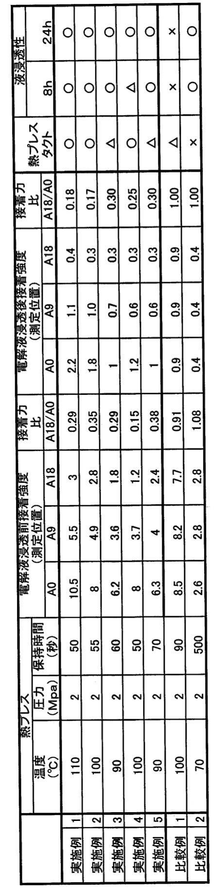
表1に示すように、上記一試験例によれば、電解液を電極に含有させる前後のいずれにおいても、接着力比が、0.1以上0.9以下である場合に、生産性及び液回り性(液浸透性)の両方に優れる電極体を作製することができた。更には、上記一試験例によれば、電解液を電極に含有させる前後のいずれにおいても、接着力比が、0.4以下である場合に、生産性及び液回り性の両方に優れる電極体を作製することができた。なお、本願発明者が行ったプレス工程の熱板の温度条件、熱板が付与する圧力条件、熱板のプレス時間を変えた複数の試験によれば、接着力比が、0.1以上、0.9以下であれば、生産性及び液回り性の両方が良好な電極体を作製でき、接着力比が、0.3以上、0.5以下であれば、生産性及び液回り性の両方に優れる電極体を作製できることを確認できた。
[好ましい構成と、それら各構成から導出される作用効果]
以上、本開示の二次電池10は、セパレータ40における少なくとも厚さ方向の一方側面と、負極(第1極)30の間に配置される接着剤50を備える。また、本開示の二次電池10では、最外層の負極30とセパレータ40の接着力をA0[N/m]とし、積層群(積層体)11Aにおいて積層方向の中央に位置する負極30とセパレータ40の接着力をA1[N/m]としたとき、A1/A0が、0.1以上0.9未満である。
以上、本開示の二次電池10は、セパレータ40における少なくとも厚さ方向の一方側面と、負極(第1極)30の間に配置される接着剤50を備える。また、本開示の二次電池10では、最外層の負極30とセパレータ40の接着力をA0[N/m]とし、積層群(積層体)11Aにおいて積層方向の中央に位置する負極30とセパレータ40の接着力をA1[N/m]としたとき、A1/A0が、0.1以上0.9未満である。
したがって、電解液を、短時間で積層方向の内側まで浸透させることができる。よって、電解液の保持量を積層方向の存在位置によらず均一な値にし易い二次電池10を短時間で製造できる。よって、二次電池10の発電性能を高くできるだけでなく、積層方向の存在位置で反応速度差が生じることも抑制できて、その結果、二次電池10の耐久性を向上でき、更には、二次電池の生産性も良好なものにできる。
また、負極30の長辺が10cm以上であって、負極30の厚さ方向の一方側面の面積が90cm2以上になるようにしてもよい。
上述のように、電解液の積層方向の中央部への液回り性(液浸透性)は、二次電池10が大容量になればなる程、低くなる。
本構成によれば、二次電池10が、負極30の長辺が10cm以上であって、負極30の厚さ方向の一方側面の面積が90cm2以上となる大容量の電池になる。しがって、本開示の技術の主要な作用効果の1つである電解液の優れた液回り性のおかげで、接着剤を用いた従来構成の二次電池との比較において、二次電池10の発電性能や耐久性を各段に向上させることができる。
また、セパレータ40における厚さ方向の他方側面と、正極20の間に配置される第2接着剤を備えてもよい。また、最外層の正極20とセパレータ40の接着力をA2[N/m]とし、積層体において積層方向の中央に位置する正極20とセパレータ40の接着力をA3[N/m]としたとき、A3/A2が、0.1以上0.9未満でもよい。
本構成によれば、正極20とセパレータ40との間に関しても、電解液が電極群11Aの積層方向の中央部に浸透し易くなる。よって、二次電池10の発電性能、耐久性、量産性を更に良好なものにできる。
また、セパレータ40において接着剤が塗布される一方側面が、イオン透過性及び絶縁性を有する多孔質基材(例えば、ポリオレフィン基材)に含まれてもよい。
本構成によれば、セパレータ40と電極(正極及び負極の少なくとも一方)との間に作用する接着力を大きくでき、電極に対するセパレータ40の位置ずれを大きく抑制できる。
また、セパレータ40の厚さ方向の他方側面にも接着剤が塗布され、セパレータ40のその他方側面がイオン透過性及び絶縁性を有する多孔質基材(例えば、ポリオレフィン基材)に含まれてもよい。
本構成によれば、セパレータ40と正極20との間に作用する接着力を大きくできると共に、セパレータ40と負極30との間に作用する接着力も大きくできる。
また、接着剤がセパレータ40における少なくとも厚さ方向の一方側面に面積密度が略一定になるように塗布されており、接着剤において接着している部分の面積密度が積層方向で変動してもよい。
図6は、積層型の電極体における、積層方向(矢印Aで示す)の位置と、電極とセパレータの接着力との関係を示す模式図である。図6(c)に示すように、本開示の技術では、積層方向の位置を縦軸とし、接着力を横軸とした二次元グラフにおいて、電極とセパレータの接着力の分布は、積層方向の両側端部が大きくて積層方向の中央部に極小値を有するような線対称に近い関数fになる。
ここで、このような関数は、積層方向の位置を縦軸とし、プレス工程で熱板から積層体に付与される熱量を横軸した二次元グラフにおいて、プレス工程で熱板から積層体に付与される熱量の分布(温度分布)を示す関数と類似の振る舞いを示す。すなわち、プレス工程で熱板から積層体に付与される熱量の分布(温度分布)も、図6(c)に示すような、積層方向の両側端部が大きくて積層方向の中央部に極小値を有するような線対称に近い関数になる。
本変形例によれば、そのような熱量の分布(温度分布)の振る舞いを巧みに利用して、積層方向の内側(中央側)の接着力を、積層方向の外側の接着力に対して容易に小さくすることができる。すなわち、本変形例によれば、接着剤をセパレータにおける少なくとも厚さ方向の一方側面に面積密度が略一定になるように塗布するが、図6(c)にfで示す関数と類似の傾向を示す熱プレス工程でも熱量の分布(温度分布)を用いて、積層方向の内側の接着剤において溶融する量を積層方向の外側の接着剤において溶融する量よりも小さくし、積層方向の内側の接着剤において接着力を発現する接着部分の量を、積層方向の外側の接着剤において接着力を発現する接着部分の量よりも小さくする。
詳しくは、図7は、第1の電極群11Aの積層方向の内側の一部を高さ方向に略直交する平面で切断したときの拡大模式断面図であり、図5と同様に、接着剤50において接着力を発現していない部分の図示は、省略している拡大模式断面図である。ここで、塗布する接着剤50の面積密度は、積層方向の外側も内側も同一であるが、図5及び図7に示すように、図6(c)にfで示す関数と類似の傾向を示す熱量の分布(温度分布)を用いて、接着剤50において接着力を発現する接着部分50a,50bの量を、積層方向の内側の方が積層方向の外側よりも小さくすることができる。よって、積層方向の内側(中央側)の接着力を、積層方向の外側の接着力に対して容易に小さくすることができる。
従来、セパレータに塗布した接着剤の一部を溶融しない物理条件にすると、せっかく塗布した接着剤の一部が効力を発現せず、材料費の増大につながるため、そのような物理条件でプレス工程を行うことは回避されていた。
しかし、接着剤50をセパレータ40に面積密度が略一定になるように塗布すると、接着剤が塗布されている量が異なる複数の異なるセパレータを用いて電極体を作製した場合との比較において、量産性を格段に高くできるという上記問題点をはるかに凌駕する顕著な作用効果を獲得できる。よって、本変形例によれば、積層方向の内側(中央側)の接着力が、積層方向の外側の接着力に対して小さい電極体を格段に容易に作製でき、更には、量産性も格段に高くすることができる。
なお、本願開示の技術は、積層体の積層方向の内側(中央側)の接着力を、積層方向の外側の接着力よりも小さくすることにあるので、接着剤が塗布されている量が異なる複数の異なるセパレータを用いて電極体を作製してもよい。
また、セパレータが、九十九折りで折り込まれていてもよい。
本構成によれば、積層体(電極群、電極体)の取り扱い性を向上させることができる。
また、本開示の積層型の電極体11を有する二次電池10を製造するときに、積層型の電極体11を熱プレス工程で、接着剤50の少なくとも一部を溶着させることで製造するようにしてもよい。本構成によれば、本開示の積層型の電極体11を有する二次電池10を容易に作製することができる。
以上、二次電池が、積層型の電極体を備える場合について説明した。次に、二次電池が、巻回型の電極体を備える場合について説明する。図8は、巻回型の角形二次電池110の平面図であり、図9は、角形二次電池110の正面図である。また、図10(a)は、図8のA-A線断面図であり、図10(b)は、図10(a)のB-B線断面図であり、図10(c)は、図10(a)のC-C線断面図である。また、図11Aは、角形二次電池110が含む正極の平面図であり、図11Bは、角形二次電池110が含む負極の平面図である。また、図12は、角形二次電池110が含む偏平状の巻回電極体の巻回終了端側を展開した斜視図である。なお、巻回型の角形二次電池110の各部材の材料としては、上述の積層型の角形二次電池10の対応部材の材料と同一の材料を用いることができる。よって、以下の説明では、各部材の材料に関し、簡単に述べるか又は説明を省略する。
図8~図10、及び図12に示すように、角形二次電池(以下、単に二次電池という)110は、外装缶(角形外装缶)125(図8~図10参照)と、封口板123(図8参照)と、偏平状の巻回電極体114(図9(a)、図12参照)とを備える。外装缶125は、例えばアルミニウム又はアルミニウム合金からなり、高さ方向一方側に開口部を有する。図9に示すように、外装缶125は、底部140、一対の第1側面141、及び一対の第2側面142を有し、第2側面142は、第1側面141よりも大きくなっている。図10(a)に示すように、封口板123は外装缶125の開口部に嵌合される。封口板123と外装缶125との嵌合部を接合することで、角形の電池ケース145が構成される。なお、巻回型の二次電池110における各部材の材料としては、積層型の角形二次電池10における対応部材の材料と同一の材料を採用することができる。よって、以下の巻回型の二次電池110の説明では、各部材の材料に関し、簡単に述べるか又は説明を省略する。
図12に示すように、巻回電極体114は、正極111と負極112とがセパレータ113を介して互いに絶縁された状態で巻回された構造を有する。巻回電極体114の最外面側はセパレータ113で被覆され、負極112は正極111よりも外周側に配置される。図11Aに示すように、正極111は、厚さが10~20μm程度のアルミニウム又はアルミニウム合金箔からなる帯状の正極芯体115の両面に正極合材スラリーを塗布し、乾燥及び圧縮した後、所定寸法に帯状に切断する。正極合材スラリーは、正極活物質、導電剤、及び結着剤等を含む。このとき、幅方向の一方側の端部に、長手方向に沿って両面に正極合材層111aが形成されていない正極芯体露出部115aが形成されるようにする。この正極芯体露出部115aの少なくとも一方側の表面には、例えば正極合材層111aに隣接するように、正極芯体露出部115aの長さ方向に沿って正極保護層111bが形成されることが好ましい。正極保護層111bには、絶縁性無機粒子と結着剤とが含まれる。この正極保護層111bは、正極合材層111aよりも導電性が低い。正極保護層111bを設けることにより、異物等により負極合材層112aと正極芯体115との短絡を防止できる。また、正極保護層111bに導電性無機粒子を含有させることができる。なお、正極保護層111bは、設けられなくてもよい。
一方、図11Bに示すように、負極112は、厚さが5~15μm程度の銅又は銅合金箔からなる帯状の負極芯体116の両面に負極合材スラリーを塗布し、乾燥及び圧縮した後、所定寸法に帯状に切断する。負極合材スラリーは、負極活物質、及び結着剤等を含む。このとき、長手方向に沿って両面に負極合材層112aが形成されていない負極芯体露出部116aが形成されるようにする。なお、正極芯体露出部115aないし負極芯体露出部116aは、それぞれ正極111ないし負極112の幅方向の両側の端部に沿って形成してもよい。
図12に示すように、正極芯体露出部115aと負極合材層112aが重ならないように、また、負極芯体露出部116aと正極合材層111aが重ならないように、正極111及び負極112を巻回電極体114の幅方向(正極111及び負極112の幅方向)にずらして配置される。そして、正極111及び負極112を、少なくとも厚さ方向の一方側面に面積密度が略一定となっている接着剤が塗布されているセパレータ113を挟んで互いに絶縁した状態で巻回して巻回体を形成する。そして、形成した巻回体を、一対の熱板で挟み込んで、偏平状に成形することで、偏平状の巻回電極体114が作製される。巻回電極体114は、巻回軸が延びる方向(帯状の正極111、帯状の負極112、及び帯状のセパレータ113を矩形状に展開したときの幅方向に一致)の一方側端部に複数枚積層された正極芯体露出部115aを備え、他方側端部に複数枚積層された負極芯体露出部116aを備える。セパレータ113としては、好ましくは、ポリオレフィン製多孔質フィルムを使用できる。セパレータ113の幅は、正極合材層111a及び正極保護層111bを被覆できると共に負極合材層112aの幅よりも大きいことが好ましい。
後で詳述するが、複数枚積層された正極芯体露出部115aは、正極集電体117(図10(a)参照)を介して正極端子118に電気的に接続され、複数枚積層された負極芯体露出部116aは、負極集電体119(図10(a)参照)を介して負極端子120に電気的に接続される。また、詳述しないが、図10(a)に示すように、正極集電体117と正極端子118との間には、電池ケース145の内部のガス圧が所定値以上となった時に作動する電流遮断機構127が設けられることが好ましい。
図8、図9及び図10(a)に示すように、正極端子118及び負極端子120の夫々は、絶縁部材121、122を介して封口板123に固定される。封口板123は、電池ケース145内のガス圧が電流遮断機構127の作動圧よりも高くなったときに開放されるガス排出弁128を有する。正極集電体117、正極端子118及び封口板123は、それぞれアルミニウム又はアルミニウム合金で形成され、負極集電体119及び負極端子120は、それぞれ銅又は銅合金で形成される。図10(c)に示すように、偏平状の巻回電極体114は、封口板123側を除く周囲に絶縁性の絶縁シート(樹脂シート)124を介在させた状態で一面が開放された外装缶125内に挿入される。
図10(b)及び図10(c)に示すように、正極111側では、巻回されて積層された複数枚の正極芯体露出部115aは、厚み方向の中央部に収束されてさらに2分割され、正極芯体露出部115aが収束され、その間に正極用中間部材130が配置される。正極用中間部材130は樹脂材料からなり、正極用中間部材130には、導電性の正極用導電部材129が、1以上、例えば2個保持される。正極用導電部材129は、例えば円柱状のものが用いられ、積層された正極芯体露出部115aと対向する両端部にプロジェクションとして作用する円錐台状の突起が形成されている。
負極112側でも、巻回されて積層された複数枚の負極芯体露出部116aは、厚み方向の中央側に収束されてさらに2分割され、負極芯体露出部116aが収束され、その間に負極用中間部材132が配置される。負極用中間部材132は、樹脂材料からなり、負極用中間部材132には、負極用導電部材131が、1以上、例えば2個保持される。負極用導電部材131は、例えば円柱状のものが用いられ、積層された負極芯体露出部116aと対向する両端部に、プロジェクションとして作用する円錐台状の突起が形成されている。
正極用導電部材129と、その延在方向の両側に配置されている収束された正極芯体露出部115aは、接合されて電気的に接続され、収束された正極芯体露出部115aと、その電池ケース145の奥行方向外側に配置された正極集電体117も接合されて電気的に接続される。また、同様に、負極用導電部材131と、その両側に配置されて収束されている負極芯体露出部116aは接合されて電気的に接続され、収束された負極芯体露出部116aと、その電池ケース145の奥行方向外側に配置された負極集電体119も、接合されて電気的に接続される。正極集電体117の正極芯体露出部115a側とは反対側の端部は、正極端子118に電気的に接続され、負極集電体119の負極芯体露出部116a側とは反対側の端部は、負極端子120に電気的に接続される。その結果、正極芯体露出部115aが正極端子118に電気的に接続され、負極芯体露出部116aが負極端子120に電気的に接続される。
巻回電極体114、正極及び負極用中間部材130,132、及び正極及び負極用導電部材129,131は接続され、一体構造を構成する。正極用導電部材129は、正極芯体115と同じ材料であるアルミニウム又はアルミニウム合金製のものが好ましく、負極用導電部材131は、負極芯体116と同じ材料である銅又は銅合金製のものが好ましい。正極用導電部材129及び負極用導電部材131の形状は、同じであっても異なっていてもよい。
正極芯体露出部115aと正極集電体117の接続、及び負極芯体露出部116aと負極集電体119の接続は、抵抗溶接、レーザ溶接や超音波溶接等を用いてもよい。また、正極用中間部材130及び負極用中間部材132を用いなくてもよい。
図8に示すように、封口板123には電解液注液孔126が設けられる。正極集電体117、負極集電体119、及び封口板123等が取り付けられた巻回電極体114を、外装缶125内に配置する。このとき、巻回電極体114を箱状ないし袋状に成形した絶縁シート124内に配置した状態で、巻回電極体114を外装缶125内に挿入することが好ましい。その後、封口板123と外装缶125との嵌合部をレーザ溶接し、その後、電解液注液孔126から非水電解液を注液する。その後、電解液注液孔126を密封することで二次電池110を作製する。電解液注液孔126の密封は、例えばブラインドリベットや溶接等で実行される。
なお、巻回電極体114が、その巻回軸が外装缶125の底部140と平行となる向きに配置される場合について説明したが、巻回電極体が、その巻回軸が外装缶125の底部140と垂直となる向きに配置される構成でもよい。
以上、巻回型の二次電池110の一例について例示したが、上述の巻回型の二次電池110に限らず如何なる巻回型の二次電池110においても、電解質(電解液)が中央の空洞側に浸透しにくいという課題がある。
すなわち、図6及び図13に示すように、積層型の電極体11における積層方向(熱板でのプレス方向と一致)Aと、巻回電極体(巻回型の電極体)114における熱板でのプレス方向Bは、互いに対応する。そして、巻回電極体114を、熱プレス工程で、偏平形状にプレスして接着剤を溶融させるとき、外周側の温度よりも内周側の温度が低くなる。すなわち、積層型の電極体11の積層方向の外側が、巻回電極体114の外周側に対応し、積層型の電極体11の積層方向の内側(中央側)が、巻回電極体114の内周側(空洞側)に対応する。よって、次の構成を有する巻回電極体114を作製すれば、積層型の電極体11と同様に、それを用いた二次電池110の発電性能、耐久性、及び量産性を向上させることができる。
詳しくは、二次電池110は、正極芯体115及び正極芯体115上に配置された正極活物質を有する帯状の正極111と、負極芯体116及び負極芯体116上に配置された負極活物質を有する帯状の負極112が、帯状のセパレータ113を介して5巻以上巻回された巻回体を備える。また、二次電池110は、上記巻回体が、セパレータ113における少なくとも厚さ方向の片側面と、少なくとも一方の電極(第1極)との間に配置される接着剤を備える。そして、最外周に位置する少なくとも一方の電極(第1極)とセパレータの接着力をA0[N/m]とし、最内周に位置する上記少なくとも一方の電極(第1極)とセパレータの接着力をA1[N/m]としたとき、A1/A0が、0.1以上0.9未満である。
したがって、二次電池110は、発電性能、耐久性、及び量産性が良好なものになる。
また、巻回体が、偏平形状を有し、電池110の高さ方向の巻回体の長さが10cm以上であって、電池110の横方向の巻回体の長さが9cm以上でもよい。
巻回体における電解液の内周側への液回り性(液浸透性)は、二次電池110が大容量になればなる程、低くなる。
本構成によれば、二次電池110が、巻回体の厚さが10cm以上であって、最外周の周辺長が9cm以上となる大容量の電池になる。しがって、本開示の技術の主要な作用効果の1つである電解液の優れた液回り性のおかげで、二次電池110の発電性能や耐久性を各段に向上させることができる。
また、セパレータ113における厚さ方向の他方側面と、他方の電極の間に配置される第2接着剤を備え、最外周に位置する他方の電極と前記セパレータの接着力をA2[N/m]とし、最内周に位置する他方の電極とセパレータの接着力をA3[N/m]としたとき、A3/A2が、0.1以上0.9未満でもよい。
本構成によれば、巻回体の内周側における他方の電極とセパレータ113の間の液回り性(液浸透性)も大きくすることができる。しがって、二次電池110の発電性能、耐久性、及び量産性を更に向上させることができる。
また、セパレータ113において接着剤が配置される少なくとも一方側面が、イオン透過性及び絶縁性を有する多孔質基材(例えば、ポリオレフィン基材)に含まれてもよい。
本構成によれば、セパレータ113と少なくとも一方の電極(正極及び負極の少なくとも一方)との間に作用する接着力を大きくでき、電極に対するセパレータ113の位置ずれを大きく抑制できる。
また、セパレータ113の厚さ方向の他方側面にも接着剤が塗布され、セパレータ113のその他方側面がイオン透過性及び絶縁性を有する多孔質基材(例えば、ポリオレフィン基材)に含まれてもよい。
本構成によれば、セパレータ113と正極111との間に作用する接着力を大きくできると共に、セパレータ113と負極112との間に作用する接着力も大きくできる。
また、接着剤がセパレータ113における少なくとも厚さ方向の一方側面に面積密度が略一定になるように塗布されていてもよい。そして、接着剤において接着している部分の面積密度が巻回体の層ごとに変動するようにしてもよく、より詳しくは、外周側の層よりも内周側の層の接着部分の面積密度が小さくなるように変動させてもよい。
本構成によれば、二次電池の生産性を格段に向上させることができる。
また、本開示の巻回電極体114を有する二次電池110を製造するときに、巻回電極体114を熱プレス工程で、接着剤の少なくとも一部を溶着させることで製造するようにしてもよい。本構成によれば、本開示の巻回電極体114を有する二次電池110を容易に作製することができる。
10,110 二次電池
11 電極体
11A,11B 電極群
20,111 正極
115 正極芯体
30,112 負極
116 負極芯体
40,113 セパレータ
40a 基材
40b 耐熱層
50 接着剤
50a,50b 接着剤において接着している接着部分
111a 正極合材層
112a 負極合材層
114 巻回電極体。
11 電極体
11A,11B 電極群
20,111 正極
115 正極芯体
30,112 負極
116 負極芯体
40,113 セパレータ
40a 基材
40b 耐熱層
50 接着剤
50a,50b 接着剤において接着している接着部分
111a 正極合材層
112a 負極合材層
114 巻回電極体。
Claims (13)
- 第1極芯体及び前記第1極芯体上に配置された第1極活物質を有する複数の第1極と、
第2極芯体及び前記第2極芯体上に配置された第2極活物質を有する複数の第2極と、
1以上のセパレータと、
前記セパレータにおける少なくとも厚さ方向の一方側面と、前記第1極の間に配置される接着剤と、を備え、
前記複数の第1極と前記複数の第2極は、前記セパレータを介して交互に積層され、
前記複数の第1極及び前記複数の第2極を含む積層体は、10以上の前記第1極を有し、
最外層の前記第1極と前記セパレータの接着力をA0[N/m]とし、前記積層体において積層方向の中央に位置する前記第1極と前記セパレータの接着力をA1[N/m]としたとき、A1/A0が、0.1以上0.9未満である、二次電池。 - 第1極芯体及び前記第1極芯体上に配置された第1極活物質を有する帯状の第1極と、第2極芯体及び前記第2極芯体上に配置された第2極活物質を有する帯状の第2極が、帯状のセパレータを介して5巻以上巻回された巻回体を備え、
前記巻回体は、前記セパレータにおける少なくとも厚さ方向の一方側面と、前記第1極との間に配置される接着剤を有し、
最外周に位置する前記第1極と前記セパレータの接着力をA0[N/m]とし、最内周に位置する前記第1極と前記セパレータの接着力をA1[N/m]としたとき、A1/A0が、0.1以上0.9未満である、二次電池。 - 前記第1極の長辺が10cm以上であって、前記第1極の厚さ方向の一方側面の面積が90cm2以上である、請求項1に記載の二次電池。
- 前記セパレータにおける厚さ方向の他方側面と、前記第2極の間に配置される第2接着剤を備え、
最外層の前記第2極と前記セパレータの接着力をA2[N/m]とし、前記積層体において積層方向の中央に位置する前記第2極と前記セパレータの接着力をA3[N/m]としたとき、A3/A2が、0.1以上0.9未満である、請求項1又は3に記載の二次電池。 - 前記巻回体が、偏平形状を有し、
前記二次電池の高さ方向における前記巻回体の長さが10cm以上であって、前記二次電池の横方向における前記巻回体の長さが9cm以上である、請求項2に記載の二次電池。 - 前記セパレータにおける厚さ方向の他方側面と、前記第2極の間に配置される第2接着剤を備え、
最外周に位置する前記第2極と前記セパレータの接着力をA2[N/m]とし、最内周に位置する前記第2極と前記セパレータの接着力をA3[N/m]としたとき、A3/A2が、0.1以上0.9未満である、請求項2又は5に記載の二次電池。 - 前記一方側面が、イオン透過性及び絶縁性を有する多孔質基材に含まれる、請求項1から6までのいずれか1つに記載の二次電池。
- 前記他方側面が、イオン透過性及び絶縁性を有する多孔質基材に含まれる、請求項4又は6に記載の二次電池。
- 前記接着剤が前記セパレータの前記一方側面に面積密度が略一定になるように塗布されており、
前記接着剤において接着している部分の面積密度が前記積層方向で変動する、請求項1、3又は4に記載の二次電池。 - 前記接着剤が前記セパレータの前記一方側面に面積密度が略一定になるように塗布されており、
前記接着剤において接着している部分の面積密度が巻回体の層ごとに変動する、請求項2、5又は6に記載の二次電池。 - 前記セパレータが、九十九折りで折り込まれている、請求項1、3、4、又は9に記載の二次電池。
- 前記二次電池は、非水電解質二次電池である、請求項1から11のいずれかに記載の二次電池。
- 請求項1から12までのいずれか1つの二次電池を製造する二次電池の製造方法であって、
熱プレス工程で、前記接着剤の少なくとも一部を溶着させる、二次電池の製造方法。
Priority Applications (4)
| Application Number | Priority Date | Filing Date | Title |
|---|---|---|---|
| EP20904827.1A EP4084184A4 (en) | 2019-12-26 | 2020-12-15 | SECONDARY BATTERY AND ITS PRODUCTION METHOD |
| JP2021567286A JPWO2021131877A1 (ja) | 2019-12-26 | 2020-12-15 | |
| CN202080089149.5A CN114846671A (zh) | 2019-12-26 | 2020-12-15 | 二次电池及其制造方法 |
| US17/786,820 US20230031407A1 (en) | 2019-12-26 | 2020-12-15 | Secondary battery and production method for same |
Applications Claiming Priority (2)
| Application Number | Priority Date | Filing Date | Title |
|---|---|---|---|
| JP2019236097 | 2019-12-26 | ||
| JP2019-236097 | 2019-12-26 |
Publications (1)
| Publication Number | Publication Date |
|---|---|
| WO2021131877A1 true WO2021131877A1 (ja) | 2021-07-01 |
Family
ID=76574546
Family Applications (1)
| Application Number | Title | Priority Date | Filing Date |
|---|---|---|---|
| PCT/JP2020/046639 WO2021131877A1 (ja) | 2019-12-26 | 2020-12-15 | 二次電池、及びその製造方法 |
Country Status (5)
| Country | Link |
|---|---|
| US (1) | US20230031407A1 (ja) |
| EP (1) | EP4084184A4 (ja) |
| JP (1) | JPWO2021131877A1 (ja) |
| CN (1) | CN114846671A (ja) |
| WO (1) | WO2021131877A1 (ja) |
Cited By (1)
| Publication number | Priority date | Publication date | Assignee | Title |
|---|---|---|---|---|
| JP7459157B2 (ja) | 2022-03-14 | 2024-04-01 | プライムプラネットエナジー&ソリューションズ株式会社 | 電池 |
Families Citing this family (1)
| Publication number | Priority date | Publication date | Assignee | Title |
|---|---|---|---|---|
| JP2024119116A (ja) * | 2023-02-22 | 2024-09-03 | プライムプラネットエナジー&ソリューションズ株式会社 | 蓄電デバイスの製造方法ならびに蓄電デバイス用セパレータ |
Citations (6)
| Publication number | Priority date | Publication date | Assignee | Title |
|---|---|---|---|---|
| WO1999026306A1 (fr) * | 1997-11-19 | 1999-05-27 | Mitsubishi Denki Kabushiki Kaisha | Batterie secondaire aux ions de lithium et fabrication de cette derniere |
| JP2011054502A (ja) * | 2009-09-04 | 2011-03-17 | Hitachi Maxell Ltd | リチウム二次電池およびその製造方法 |
| JP2014026943A (ja) * | 2012-07-30 | 2014-02-06 | Nissan Motor Co Ltd | 積層構造電池 |
| JP2014120456A (ja) * | 2012-12-19 | 2014-06-30 | Nissan Motor Co Ltd | 二次電池 |
| JP2018067396A (ja) * | 2016-10-17 | 2018-04-26 | 株式会社カネカ | リチウムイオン二次電池 |
| WO2019156172A1 (ja) * | 2018-02-08 | 2019-08-15 | 積水化学工業株式会社 | リチウムイオン二次電池、リチウムイオン二次電池用負極構造体、及びリチウムイオン二次電池の製造方法 |
Family Cites Families (4)
| Publication number | Priority date | Publication date | Assignee | Title |
|---|---|---|---|---|
| JP2013243070A (ja) * | 2012-05-22 | 2013-12-05 | Sanyo Electric Co Ltd | 巻回電極体を備えた電池 |
| PL3352248T3 (pl) * | 2016-04-01 | 2020-06-29 | Lg Chem, Ltd. | Separator zawierający warstwę adhezyjną dla urządzenia elektrochemicznego i zespół elektrod go zawierający |
| WO2018186205A1 (ja) * | 2017-04-07 | 2018-10-11 | 株式会社村田製作所 | 二次電池およびその製造方法 |
| CN110546804B (zh) * | 2017-05-12 | 2024-02-27 | 松下控股株式会社 | 非水电解质二次电池 |
-
2020
- 2020-12-15 US US17/786,820 patent/US20230031407A1/en active Pending
- 2020-12-15 EP EP20904827.1A patent/EP4084184A4/en active Pending
- 2020-12-15 WO PCT/JP2020/046639 patent/WO2021131877A1/ja unknown
- 2020-12-15 JP JP2021567286A patent/JPWO2021131877A1/ja active Pending
- 2020-12-15 CN CN202080089149.5A patent/CN114846671A/zh active Pending
Patent Citations (6)
| Publication number | Priority date | Publication date | Assignee | Title |
|---|---|---|---|---|
| WO1999026306A1 (fr) * | 1997-11-19 | 1999-05-27 | Mitsubishi Denki Kabushiki Kaisha | Batterie secondaire aux ions de lithium et fabrication de cette derniere |
| JP2011054502A (ja) * | 2009-09-04 | 2011-03-17 | Hitachi Maxell Ltd | リチウム二次電池およびその製造方法 |
| JP2014026943A (ja) * | 2012-07-30 | 2014-02-06 | Nissan Motor Co Ltd | 積層構造電池 |
| JP2014120456A (ja) * | 2012-12-19 | 2014-06-30 | Nissan Motor Co Ltd | 二次電池 |
| JP2018067396A (ja) * | 2016-10-17 | 2018-04-26 | 株式会社カネカ | リチウムイオン二次電池 |
| WO2019156172A1 (ja) * | 2018-02-08 | 2019-08-15 | 積水化学工業株式会社 | リチウムイオン二次電池、リチウムイオン二次電池用負極構造体、及びリチウムイオン二次電池の製造方法 |
Non-Patent Citations (1)
| Title |
|---|
| See also references of EP4084184A4 * |
Cited By (1)
| Publication number | Priority date | Publication date | Assignee | Title |
|---|---|---|---|---|
| JP7459157B2 (ja) | 2022-03-14 | 2024-04-01 | プライムプラネットエナジー&ソリューションズ株式会社 | 電池 |
Also Published As
| Publication number | Publication date |
|---|---|
| JPWO2021131877A1 (ja) | 2021-07-01 |
| EP4084184A1 (en) | 2022-11-02 |
| EP4084184A4 (en) | 2023-12-27 |
| CN114846671A (zh) | 2022-08-02 |
| US20230031407A1 (en) | 2023-02-02 |
Similar Documents
| Publication | Publication Date | Title |
|---|---|---|
| JP5697276B2 (ja) | 新規な構造を有する電極組立体およびその製造方法 | |
| CN110546804B (zh) | 非水电解质二次电池 | |
| WO2017163932A1 (ja) | 非水電解質二次電池 | |
| WO2011002064A1 (ja) | ラミネート形電池 | |
| WO2017077698A1 (ja) | 蓄電装置用電極板及び蓄電装置 | |
| WO2018168628A1 (ja) | 非水電解質二次電池 | |
| WO2021131877A1 (ja) | 二次電池、及びその製造方法 | |
| WO2021131878A1 (ja) | 二次電池 | |
| JP2011198742A (ja) | ラミネート形電池 | |
| JP5999433B2 (ja) | 非水電解液二次電池及びその製造方法 | |
| WO2021131879A1 (ja) | 二次電池 | |
| CN109923700B (zh) | 非水电解质二次电池用电极以及非水电解质二次电池 | |
| JP2011129446A (ja) | ラミネート形電池 | |
| WO2019069890A1 (ja) | 非水電解質二次電池 | |
| US11502375B2 (en) | Separator for nonaqueous electrolyte secondary batteries and nonaqueous electrolyte secondary battery | |
| WO2021131880A1 (ja) | 二次電池 | |
| JP2011216205A (ja) | ラミネート形電池およびその製造方法 | |
| JP2011216209A (ja) | ラミネート形電池およびその製造方法 | |
| JP7320166B2 (ja) | 二次電池 | |
| KR20180032763A (ko) | 전극과 분리막이 부분 결착된 전극조립체 | |
| JP2011108538A (ja) | ラミネート形電池 | |
| JP6681017B2 (ja) | 電極体を有する二次電池 | |
| JP7430665B2 (ja) | 二次電池の集電体およびその製造方法、ならびに二次電池 | |
| WO2021166720A1 (ja) | 非水電解質二次電池及びその製造方法 | |
| WO2022196445A1 (ja) | 非水電解質二次電池 |
Legal Events
| Date | Code | Title | Description |
|---|---|---|---|
| 121 | Ep: the epo has been informed by wipo that ep was designated in this application |
Ref document number: 20904827 Country of ref document: EP Kind code of ref document: A1 |
|
| ENP | Entry into the national phase |
Ref document number: 2021567286 Country of ref document: JP Kind code of ref document: A |
|
| NENP | Non-entry into the national phase |
Ref country code: DE |
|
| ENP | Entry into the national phase |
Ref document number: 2020904827 Country of ref document: EP Effective date: 20220726 |